EP3543710A2 - Power efficient heater control of air data sensor - Google Patents
Power efficient heater control of air data sensor Download PDFInfo
- Publication number
- EP3543710A2 EP3543710A2 EP19164158.8A EP19164158A EP3543710A2 EP 3543710 A2 EP3543710 A2 EP 3543710A2 EP 19164158 A EP19164158 A EP 19164158A EP 3543710 A2 EP3543710 A2 EP 3543710A2
- Authority
- EP
- European Patent Office
- Prior art keywords
- heating element
- temperature
- probe
- heat
- heater control
- Prior art date
- Legal status (The legal status is an assumption and is not a legal conclusion. Google has not performed a legal analysis and makes no representation as to the accuracy of the status listed.)
- Granted
Links
Images




Classifications
-
- H—ELECTRICITY
- H05—ELECTRIC TECHNIQUES NOT OTHERWISE PROVIDED FOR
- H05B—ELECTRIC HEATING; ELECTRIC LIGHT SOURCES NOT OTHERWISE PROVIDED FOR; CIRCUIT ARRANGEMENTS FOR ELECTRIC LIGHT SOURCES, IN GENERAL
- H05B1/00—Details of electric heating devices
- H05B1/02—Automatic switching arrangements specially adapted to apparatus ; Control of heating devices
- H05B1/0227—Applications
- H05B1/023—Industrial applications
- H05B1/0236—Industrial applications for vehicles
-
- G—PHYSICS
- G01—MEASURING; TESTING
- G01P—MEASURING LINEAR OR ANGULAR SPEED, ACCELERATION, DECELERATION, OR SHOCK; INDICATING PRESENCE, ABSENCE, OR DIRECTION, OF MOVEMENT
- G01P13/00—Indicating or recording presence, absence, or direction, of movement
- G01P13/02—Indicating direction only, e.g. by weather vane
- G01P13/025—Indicating direction only, e.g. by weather vane indicating air data, i.e. flight variables of an aircraft, e.g. angle of attack, side slip, shear, yaw
-
- G—PHYSICS
- G01—MEASURING; TESTING
- G01P—MEASURING LINEAR OR ANGULAR SPEED, ACCELERATION, DECELERATION, OR SHOCK; INDICATING PRESENCE, ABSENCE, OR DIRECTION, OF MOVEMENT
- G01P21/00—Testing or calibrating of apparatus or devices covered by the preceding groups
- G01P21/02—Testing or calibrating of apparatus or devices covered by the preceding groups of speedometers
- G01P21/025—Testing or calibrating of apparatus or devices covered by the preceding groups of speedometers for measuring speed of fluids; for measuring speed of bodies relative to fluids
-
- G—PHYSICS
- G01—MEASURING; TESTING
- G01P—MEASURING LINEAR OR ANGULAR SPEED, ACCELERATION, DECELERATION, OR SHOCK; INDICATING PRESENCE, ABSENCE, OR DIRECTION, OF MOVEMENT
- G01P5/00—Measuring speed of fluids, e.g. of air stream; Measuring speed of bodies relative to fluids, e.g. of ship, of aircraft
- G01P5/14—Measuring speed of fluids, e.g. of air stream; Measuring speed of bodies relative to fluids, e.g. of ship, of aircraft by measuring differences of pressure in the fluid
- G01P5/16—Measuring speed of fluids, e.g. of air stream; Measuring speed of bodies relative to fluids, e.g. of ship, of aircraft by measuring differences of pressure in the fluid using Pitot tubes, e.g. Machmeter
- G01P5/165—Arrangements or constructions of Pitot tubes
-
- G—PHYSICS
- G05—CONTROLLING; REGULATING
- G05D—SYSTEMS FOR CONTROLLING OR REGULATING NON-ELECTRIC VARIABLES
- G05D23/00—Control of temperature
- G05D23/19—Control of temperature characterised by the use of electric means
- G05D23/27—Control of temperature characterised by the use of electric means with sensing element responsive to radiation
Definitions
- Exemplary embodiments pertain generally to the art of aircraft systems, and more particularly, to aircraft pressure measurement systems.
- Aircraft pressure measurement system include an air data sensor to determine airspeed, altitude and angle of attack. These air data sensors are typically constructed as a Pitot static probe and transducer. The probe utilizes small openings or apertures on the front and sides of the probe body to direct air pressure to the transducer, which in turn facilitates air pressure measurements.
- Commercial and military aircraft commonly fly in environmental conditions where ice can form on the Pitot static probe surface and openings. This ice formation has the potential to disturb the pressure measurement reading or completely block the probe openings. The result is incorrect or erroneous pressure measurement data being sent to the aircraft flight control systems or pilot.
- an aircraft includes an air data sensor and a heating element.
- the air data sensor includes a probe and transducer coupled to the probe.
- the heating element is disposed within the probe and is configured to emit heat that heats the probe.
- the aircraft further comprises a heater control system in signal communication with the heating element and a thermal sensor system.
- the thermal sensor system is configured to determine the emitted heat from the heating element based on the thermal radiation of heat released from a surface of the probe. In this manner, the heater control system selectively activates and deactivates the heating element based on the emitted heat from the heating element.
- an aircraft comprises an air data sensor and a heating element.
- the air data sensor includes a probe and transducer coupled to the probe.
- the heating element is disposed within the probe and is configured to emit heat that heats the probe.
- the heating element is configured to emit heat that heats the probe.
- the aircraft further comprises a thermal sensor system in signal communication with a diagnostic system.
- the thermal sensor system is configured to determine the emitted heat from the heating element based on thermal radiation of heat released from a surface of the probe.
- the diagnostic system is in signal communication with the thermal sensor system and the heating element.
- the diagnostic system is configured to determine the temperature of the heating element and initiate a heater diagnostic test that diagnoses the health of the heating element based on the temperature of the heating element.
- an aircraft heater control system includes an air data sensor, and a heating element coupled to the air data sensor.
- the heating element is configured to emit heat, which increases the temperature of the air data sensor.
- a thermal sensor system is located adjacent to the air data sensor and is configured to output a temperature signal indicative of a temperature of the heating element.
- An electronic hardware controller is in signal communication with the thermal sensor and the heating element. The controller is configured to selectively activate and deactivate the heating element based on the temperature of the heating element.
- a method to heat an air data sensor operable with an aircraft.
- the method comprises outputting, via a thermal sensor system in operable communication with a heating element disposed within a probe of an air data sensor, a temperature signal indicative of a temperature of the heating element based on a thermal radiation of heat released from a surface of the probe.
- the method further comprises controlling power supplied to the heating element, via a controller, to vary the emitted heat based on the temperature signal.
- a diagnostic system for an aircraft comprises an air data sensor including a probe and transducer coupled to the probe, and a heating element disposed within the probe and configured to emit heat that heats the probe.
- the diagnostic system further includes a thermal sensor system in operable communication with the air data sensor and configured to determine output a temperature signal indicative of a temperature of the heating element.
- the diagnostic system further includes a controller in operable communication with the heating element and the thermal sensor system. The controller is configured to determine the temperature of the heating element based on the temperature signal, and to initiate a heater diagnostic test that diagnoses a health of the heating element based on the temperature of the heating element.
- a method to diagnose a heating element coupled to an air data sensor operable with an aircraft.
- the method comprises emitting heat from the heating element coupled to a probe of the air data sensor to increase a temperature of the probe, and outputting, via a thermal sensor system, a temperature signal indicative of a temperature of the heating element.
- the method further comprises determining, via a controller, the temperature of the heating element based on the temperature signal, and initiating a heater diagnostic test that diagnoses a health of the heating element based on the temperature of the heating element.
- an aircraft pressure measurement system that includes an air data sensor.
- the air data sensor is constructed as a Pitot probe and a transducer.
- a heating element is disposed within the probe and emits heat in response to a supplied electrical current. The heat from the heating element aims to prevent ice from forming on the probe, or to melt ice that has already formed on the probe during low temperature conditions.
- the heat emitted from the heating element heats the probe and probe surface without heating the transducer.
- the pressure measurement system further includes a power efficient heater control system in signal communication with the transducer and the heating element.
- the heater control system implements an optics system capable detecting infrared (IR) heat emitted by the heating element.
- the heater control system utilizes the detected IR heat to dynamically or actively energize the heating element. Accordingly, the heater control system can determine more precisely when to energize the heating element and the amount of heat that should be produced by the heating element at given environmental conditions and temperatures. In this manner, heating efficiency and optimizing power consumption of the heating element is improved.
- the heater control system also provides diagnostics operations capable of determining the onset of a degrading heating element. In this manner, the heater control system can more accurately identify a faulty heating element, while also avoiding preemptive replacement and/or of the heating element.
- An aircraft 10 including an air data sensor 12 is illustrated according to a non-limiting embodiment.
- An electronic controller assembly 50 is in signal communication with the air data sensor 12.
- the electronic controller 50 includes a processor 52 and a memory unit 54.
- the memory unit 54 can store various algorithms, and data such as, threshold values, look-up tables, thermal models, etc.
- the processor 52 can execute the algorithms that may utilize the stored data to operate the control system and/or perform various diagnostic operations described herein.
- the air data sensor 12 can be constructed as a Pitot probe 13 coupled to a transducer 15.
- the probe 13 can be mounted to the body 14 of the aircraft 10, and can include one or more small openings or apertures 17 on the front and sides of the probe body to direct air pressure to the transducer 15.
- the transducer 15, in turn, can provide air pressure measurements to the controller 50.
- the air data sensor 12 is described going forward, it should be appreciated that other types of air data sensors configured to measure air data such as temperature, pressure, moisture, etc. may be implemented without departing from the scope of the invention.
- the probe 13 is not limited to any particular location.
- the aircraft 10 may be located in a high-altitude environment, which may contain High Altitude Ice Crystals and/or super cooled liquid water droplets.
- the probe 13 may encounter High Altitude Ice Crystals 16 and other types of ice while the aircraft 10 travels through the air 18.
- other examples may include coupling the controller 50 to more than one probe 13 installed on the aircraft 10, or other types of sensors installed on same aircraft 10 such as, for example, altitude sensors, speed sensors, etc.
- the aircraft 10 comprises an air data sensor 12 which can includes a probe 13 such as a Pitot probe, coupled to a transducer 15.
- a heating element 102 is coupled to probe 13 and is configured to emit heat that heats the probe 13 and probe surfaces.
- the heating element 102 is constructed as a heating element 102 embedded within the probe 13.
- the heating element 102 can be constructed, for example, as an electrically resistive coil, which emits the heat in response to an electrical current that flows therethrough.
- the heating element 102 is in signal communication with a current drive circuit 104.
- the current drive circuit 104 includes a pulse-width modulation (PWM) circuit 106 that generates a pulsed control signal, which induces current flow through the heating element 102.
- PWM pulse-width modulation
- the duty cycle of the pulsed control signal determines the level of the current. That is, as the duty cycle increases the current increases, and vice versa.
- the heater control system 100 includes a thermal sensor system 108, a signal processing unit 116, and an electronic hardware controller 50.
- the thermal sensor system 108 is located remotely from the heating element 102, but without contacting the probe 13. In at least one embodiment, the thermal sensor system 108 is located away from the probe 13 at a distance (d) ranging, for example, from about 12 centimeters (cm) (or about 5 inches) to about 38 cm (or about 15 inches).
- the thermal sensor system 108 is constructed as a pyrometer 108, which includes an optical unit 112 and a thermal detector 114.
- the optical unit 112 is configured to direct and focus thermal radiation (also referred to as IR radiation flux) 111 of heat released from the probe surface to the thermal detector 114.
- the thermal detector 114 is configured to output a temperature signal 113 indicative of a temperature of the heating element 102 based on the thermal radiation 111.
- the thermal detector 114 includes an infrared (IR) sensor configured to measure the IR radiation flux of the emitted heat.
- the output temperature signal generated by the thermal detector 114 is related to the thermal radiation or irradiance (Ee) of the heating element 102 through the Stefan-Boltzmann law, the constant of proportionality, also referred to as the Stefan-Boltzmann constant ( ⁇ ), and the emissivity ( ⁇ ) of the heating element 102.
- the thermal transfer function of the heat released from the surface of the probe 13 can indicate the heat emitted by the heating element 102.
- the signal processing unit 116 is configured to process the temperature signal 113 and convert the temperature signal 113 into a digital temperature signal 119 indicating the temperature of the heating element 102.
- the signal processing unit 116 includes an amplification stage 118, a signal conditioning stage 120, and an analog-to-digital (A/D) converter 122.
- the amplification stage 118 includes one or more amplifier circuits configured to amplify the temperature signal 113, thereby generating an amplified temperature signal 115.
- the signal conditioning stage 120 includes one or more filter circuits configured to remove electrical noise from the amplified temperature signal 115 to generate a filtered analog temperature signal 117.
- the A/D converter 122 is configured to convert the filtered analog temperature signal 117 into the digital temperature signal 119.
- the controller 50 is in signal communication with the thermal sensing unit 108 via the signal processing unit 116 and is in signal communication with the heating element 02 via the current drive circuit 104.
- the controller 50 is configured to selectively output a control signal 121 based on the digital temperature signal 119 so as to actively vary the temperature of the heating element based on the emitted heat from the heating element.
- actively varying the temperate of the heating element includes selectively activating and deactivating the pulse width modulating (PWM) circuit 106, thereby actively generating the electrical current 123 necessary to energize the heating element 102.
- the parameters of the PWM control signal output form the PWM circuit 106 can be varied so as to adjust the level of current delivered to the heating element 102.
- the controller 50 can actively heat the air data sensor as the temperature of the heating element 102 actively changes (i.e., increases and decreases).
- the controller 50 outputs the control signal 121 based a comparison between the digital temperature signal 119 and a target temperature value.
- the controller 50 outputs the control signal 121 when a temperature difference ( ⁇ T), i.e., "error", between the heating element temperature (e.g., as indicated by the digital temperature signal 119) and a target temperature value (i.e., desired temperature) exceeds a temperature error threshold value.
- ⁇ T temperature difference
- the controller 50 disconnects the control signal 121 when the temperature difference equals or falling below the temperature error threshold value.
- the controller 50 can also receive a secondary ice detection signal 125.
- the controller outputs the control signal 121 to activate the heating element 102 in response to receiving the secondary ice detection signal 125.
- the secondary ice detection signal 125 can be output from the probe 13 in response to detecting ice crystals in the air or ice buildup on the probe 13, from external input 127, or from another signal source.
- secondary ice detection signal 125 can serve as a secondary means of activating the heating element 102, and that the heater control system 100 can activate or deactivate the heating element 102 independently from the secondary ice detection signal 125.
- the heater control system 100 can actively operate the heating element 102 as described above prior to the formation of ice in the air and/or on the probe 13.
- the heater control system 100 is not only capable of actively controlling the heating element 102, but is also capable of diagnosing the operation and health of the heating element 102.
- the controller 50 is configured to initiate a heater diagnostic test in response to receiving a health status request signal 131.
- the health status request signal 131 is illustrated as being generated by an external input 127, it should be appreciated that the heater diagnostic test can be initiated by an internal signal generated by the controller 50 according to a predetermined schedule and/or another condition.
- the heater diagnostic test diagnoses the health of the heating element 102 based on the emitted heat detected by the thermal sensing unit 108.
- the health of the heating element 102 can be viewed as a deterioration of the heating element's ability to sufficiently emit heat.
- the controller 50 determines a rate at which the heating element's temperature changes starting from a first time period and ending at a second time period.
- the first time period is set when the heating element 102 is first activated and the second time period is set when the temperature of the heating element 102 (i.e., as indicated by the digital temperature signal 119) reaches a target temperature.
- the target temperature is actively determined based on a current environmental temperature measured by a temperature sensor and/or a current altitude of the aircraft 10.
- the temperature sensor can include a Total Air Temperature (TAT) probe and/or an Outside Air Temperature (OAT) probe.
- TAT Total Air Temperature
- OAT Outside Air Temperature
- the controller 50 compares the temperature change rate to a target temperature change rate to determine a temperature change rate differential, and diagnoses the health of the heating element 102 based on a difference between the temperature change rate differential and a differential threshold. In this manner, the controller 50 determines that the heating element 102 is faulty when the difference falls outside the differential threshold. In response to detecting a faulty heating element 102, the controller 50 can increase the duty cycle of the control signal generated by the PWM circuit 106, thereby increasing the current flowing through the heating element 102 so as to compensate for the heating element's reduced capability to emit heat. The controller 50 can also generate an alert signal 129 that activates an alert (e.g., an alarm, light indicator, dashboard icon, etc.) indicating a faulty or degraded heating element 102 is due for maintenance and/or replacement.
- an alert e.g., an alarm, light indicator, dashboard icon, etc.
- FIG. 6 a method of controlling a heating control system to heat an air data sensor installed on an aircraft is illustrated according to a non-limiting embodiment.
- the method begins at operation 400, and proceeds to an idle mode 402 after initial power on reset of the air data sensor.
- the method determines whether to invoke a heater control algorithm 404 or a heater diagnostic algorithm 500 (see FIG. 7 ).
- the method proceeds to operation 406 and initializes the heater control system.
- the heater control system remains in an idle state 408 (e.g., for a 2-5 milliseconds) before proceeding so as to reduce false positive measurements that can be detected upon start-up.
- a control signal for activating the heater i.e., heating element
- the heater is activated at operation 412.
- thermal radiation or IR flux is directed from an optical system to a thermal detector, which generates a temperature signal indicating the temperature of the heating element.
- the temperature of the heating element is compared to a target temperature at operation 416.
- the method increases the temperature of the heating element at operation 418, and continues regulating the heater at operation 420 by maintaining activation of the heater control system at operation 406.
- the measurement at operation 416 indicates that ( ⁇ T) satisfies the temperature threshold at operation 422
- the control signal is disconnected at operation 424 and the heater is deactivated at operation 426. Accordingly, the method exits the heater control algorithm 404 to return to the idle mode 402.
- FIG. 7 a method of diagnosing an air data sensor installed on an aircraft is illustrated according to a non-limiting embodiment.
- the method begins in a similar manner as described above with reference to FIG. 6 .
- the method begins at operation 400, and proceeds to an idle mode 402 after initial power on reset of the air data sensor.
- the method determines whether to invoke the heater diagnostic algorithm 500 or the heater control algorithm 404 (see FIG. 6 ).
- the method proceeds to operation 502 and initializes the heater diagnostic algorithm at operation 502, and activates the heater (i.e., the heating element) at operation 504 by generating a control signal for activating the heater (i.e., heating element) so as to emit heat from the heating element at operation 506.
- thermal radiation or IR flux of the emitted heat is directed from an optical system to a thermal detector.
- a temperature change rate of the heating element is determined. The temperature change rate can be determined by monitoring the rate in temperature change of the emitted heat starting from a first time period at which the heat element is initially activated to a second time period at which the temperature signal reaches a target temperature at operation 512.
- the temperature change rate is compared to a target temperature change rate to determine a temperature change rate differential.
- the heating element is determined to be healthy and operating normally as expected at operation 516.
- the temperature change rate differential fails to satisfy the differential threshold, the heating element is determined to faulty at operation 518.
- the method generates an alert at operation 520 and/or increases the current flowing through the heating element at operation 522 so as to compensate for a reduced capability of the heating element to emit heat.
- a heater control system which utilizes the detected IR heat of the heat emitted from a heating element coupled to probe to dynamically or actively control the operation of the heating element. Accordingly, the heater control system can determine more precisely when to energize heating element and how much heat should be emitted by the heating element at given environmental conditions and temperature to improve heating efficiency and optimizing power consumption.
- the heater control system also provides diagnostics operations capable of determining the onset of a degrading heating element. In this manner, the heater control system can more accurately identify a faulty heating element, while also avoiding preemptive maintenance and/or replacement of the heating element.
Landscapes
- Physics & Mathematics (AREA)
- General Physics & Mathematics (AREA)
- Engineering & Computer Science (AREA)
- Aviation & Aerospace Engineering (AREA)
- Automation & Control Theory (AREA)
- Radiation Pyrometers (AREA)
- Arrangements For Transmission Of Measured Signals (AREA)
- Investigating Or Analyzing Materials Using Thermal Means (AREA)
- Testing Or Calibration Of Command Recording Devices (AREA)
Abstract
Description
- This application claims the benefit of Indian Application No.
201811010827 filed March 23, 2018 - Exemplary embodiments pertain generally to the art of aircraft systems, and more particularly, to aircraft pressure measurement systems.
- Aircraft pressure measurement system include an air data sensor to determine airspeed, altitude and angle of attack. These air data sensors are typically constructed as a Pitot static probe and transducer. The probe utilizes small openings or apertures on the front and sides of the probe body to direct air pressure to the transducer, which in turn facilitates air pressure measurements. Commercial and military aircraft commonly fly in environmental conditions where ice can form on the Pitot static probe surface and openings. This ice formation has the potential to disturb the pressure measurement reading or completely block the probe openings. The result is incorrect or erroneous pressure measurement data being sent to the aircraft flight control systems or pilot.
- According to a non-limiting embodiment, an aircraft includes an air data sensor and a heating element. The air data sensor includes a probe and transducer coupled to the probe. The heating element is disposed within the probe and is configured to emit heat that heats the probe. The aircraft further comprises a heater control system in signal communication with the heating element and a thermal sensor system. The thermal sensor system is configured to determine the emitted heat from the heating element based on the thermal radiation of heat released from a surface of the probe. In this manner, the heater control system selectively activates and deactivates the heating element based on the emitted heat from the heating element.
- According to another non-limiting embodiment, an aircraft comprises an air data sensor and a heating element. The air data sensor includes a probe and transducer coupled to the probe. The heating element is disposed within the probe and is configured to emit heat that heats the probe. The heating element is configured to emit heat that heats the probe. The aircraft further comprises a thermal sensor system in signal communication with a diagnostic system. The thermal sensor system is configured to determine the emitted heat from the heating element based on thermal radiation of heat released from a surface of the probe. The diagnostic system is in signal communication with the thermal sensor system and the heating element. The diagnostic system is configured to determine the temperature of the heating element and initiate a heater diagnostic test that diagnoses the health of the heating element based on the temperature of the heating element.
- According to yet another non-limiting embodiment, an aircraft heater control system includes an air data sensor, and a heating element coupled to the air data sensor. The heating element is configured to emit heat, which increases the temperature of the air data sensor. A thermal sensor system is located adjacent to the air data sensor and is configured to output a temperature signal indicative of a temperature of the heating element. An electronic hardware controller is in signal communication with the thermal sensor and the heating element. The controller is configured to selectively activate and deactivate the heating element based on the temperature of the heating element.
- According to still another non-limiting embodiment, a method is provided to heat an air data sensor operable with an aircraft. The method comprises outputting, via a thermal sensor system in operable communication with a heating element disposed within a probe of an air data sensor, a temperature signal indicative of a temperature of the heating element based on a thermal radiation of heat released from a surface of the probe. The method further comprises controlling power supplied to the heating element, via a controller, to vary the emitted heat based on the temperature signal.
- According to another non-limiting embodiment, a diagnostic system for an aircraft comprises an air data sensor including a probe and transducer coupled to the probe, and a heating element disposed within the probe and configured to emit heat that heats the probe. The diagnostic system further includes a thermal sensor system in operable communication with the air data sensor and configured to determine output a temperature signal indicative of a temperature of the heating element. The diagnostic system further includes a controller in operable communication with the heating element and the thermal sensor system. The controller is configured to determine the temperature of the heating element based on the temperature signal, and to initiate a heater diagnostic test that diagnoses a health of the heating element based on the temperature of the heating element.
- According to still another non-limiting embodiment, a method is provided to diagnose a heating element coupled to an air data sensor operable with an aircraft. The method comprises emitting heat from the heating element coupled to a probe of the air data sensor to increase a temperature of the probe, and outputting, via a thermal sensor system, a temperature signal indicative of a temperature of the heating element. The method further comprises determining, via a controller, the temperature of the heating element based on the temperature signal, and initiating a heater diagnostic test that diagnoses a health of the heating element based on the temperature of the heating element.
- The following descriptions should not be considered limiting in any way. With reference to the accompanying drawings, like elements are numbered alike:
-
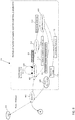
FIG. 1 is a partial view of an aircraft including an air data sensor according to a non-limiting embodiment; -
FIG. 2 illustrates an air data sensor including a probe coupled to a transducer according to a non-limiting embodiment; -
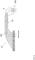
FIG. 3 is a cross-sectional view of the air data sensor ofFIG. 2 showing a heating element embedded within the probe; -
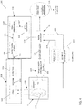
FIG. 4 is a block diagram of a heater control system according to a non-limiting embodiment; -
FIG. 5 is a block diagram illustrating a control feedback for controlling a heating element for heating the air data sensor according to a non-limiting embodiment; -
FIG. 6 is a flow diagram illustrating a method of heating an air data sensor installed on an aircraft is illustrated according to a non-limiting embodiment; and -
FIG. 7 is a flow diagram illustrating a method of diagnosing an air data sensor installed on an aircraft according to a non-limiting embodiment. - A detailed description of one or more embodiments of the disclosed apparatus and method are presented herein by way of exemplification and not limitation with reference to the Figures.
- The term "about" is intended to include the degree of error associated with measurement of the particular quantity based upon the equipment available at the time of filing the application.
- The terminology used herein is for the purpose of describing particular embodiments only and is not intended to be limiting of the present disclosure. As used herein, the singular forms "a", "an" and "the" are intended to include the plural forms as well, unless the context clearly indicates otherwise. It will be further understood that the terms "comprises" and/or "comprising," when used in this specification, specify the presence of stated features, integers, steps, operations, elements, and/or components, but do not preclude the presence or addition of one or more other features, integers, steps, operations, element components, and/or groups thereof.
- Various embodiments described herein provide an aircraft pressure measurement system that includes an air data sensor. In at least one embodiment, the air data sensor is constructed as a Pitot probe and a transducer. A heating element is disposed within the probe and emits heat in response to a supplied electrical current. The heat from the heating element aims to prevent ice from forming on the probe, or to melt ice that has already formed on the probe during low temperature conditions. In at least one embodiment, the heat emitted from the heating element heats the probe and probe surface without heating the transducer.
- In at least one embodiment, the pressure measurement system further includes a power efficient heater control system in signal communication with the transducer and the heating element. The heater control system implements an optics system capable detecting infrared (IR) heat emitted by the heating element. The heater control system utilizes the detected IR heat to dynamically or actively energize the heating element. Accordingly, the heater control system can determine more precisely when to energize the heating element and the amount of heat that should be produced by the heating element at given environmental conditions and temperatures. In this manner, heating efficiency and optimizing power consumption of the heating element is improved. The heater control system also provides diagnostics operations capable of determining the onset of a degrading heating element. In this manner, the heater control system can more accurately identify a faulty heating element, while also avoiding preemptive replacement and/or of the heating element.
- With reference now to
FIG. 1 , anaircraft 10 including anair data sensor 12 is illustrated according to a non-limiting embodiment. Anelectronic controller assembly 50 is in signal communication with theair data sensor 12. Theelectronic controller 50 includes aprocessor 52 and amemory unit 54. Thememory unit 54 can store various algorithms, and data such as, threshold values, look-up tables, thermal models, etc. Theprocessor 52 can execute the algorithms that may utilize the stored data to operate the control system and/or perform various diagnostic operations described herein. - Referring to
FIGS 2 and3 , theair data sensor 12 can be constructed as aPitot probe 13 coupled to atransducer 15. Theprobe 13 can be mounted to thebody 14 of theaircraft 10, and can include one or more small openings orapertures 17 on the front and sides of the probe body to direct air pressure to thetransducer 15. Thetransducer 15, in turn, can provide air pressure measurements to thecontroller 50. Although theair data sensor 12 is described going forward, it should be appreciated that other types of air data sensors configured to measure air data such as temperature, pressure, moisture, etc. may be implemented without departing from the scope of the invention. - Referring again to
FIG. 1 , it should also be appreciated that theprobe 13 is not limited to any particular location. As can be appreciated, theaircraft 10 may be located in a high-altitude environment, which may contain High Altitude Ice Crystals and/or super cooled liquid water droplets. As a result, theprobe 13 may encounter HighAltitude Ice Crystals 16 and other types of ice while theaircraft 10 travels through theair 18. Although only asingle probe 13 is shown, other examples may include coupling thecontroller 50 to more than oneprobe 13 installed on theaircraft 10, or other types of sensors installed onsame aircraft 10 such as, for example, altitude sensors, speed sensors, etc. - Turning now to
FIG. 4 , a power efficientheater control system 100 installed on theaircraft 10 is illustrated according to a non-limiting embodiment. As described herein, theaircraft 10 comprises anair data sensor 12 which can includes aprobe 13 such as a Pitot probe, coupled to atransducer 15. Aheating element 102 is coupled to probe 13 and is configured to emit heat that heats theprobe 13 and probe surfaces. In at least one embodiment, theheating element 102 is constructed as aheating element 102 embedded within theprobe 13. Theheating element 102 can be constructed, for example, as an electrically resistive coil, which emits the heat in response to an electrical current that flows therethrough. In at least one embodiment, theheating element 102 is in signal communication with acurrent drive circuit 104. Thecurrent drive circuit 104 includes a pulse-width modulation (PWM)circuit 106 that generates a pulsed control signal, which induces current flow through theheating element 102. The duty cycle of the pulsed control signal determines the level of the current. That is, as the duty cycle increases the current increases, and vice versa. - The
heater control system 100 includes athermal sensor system 108, asignal processing unit 116, and anelectronic hardware controller 50. Thethermal sensor system 108 is located remotely from theheating element 102, but without contacting theprobe 13. In at least one embodiment, thethermal sensor system 108 is located away from theprobe 13 at a distance (d) ranging, for example, from about 12 centimeters (cm) (or about 5 inches) to about 38 cm (or about 15 inches). In at least one embodiment, thethermal sensor system 108 is constructed as apyrometer 108, which includes anoptical unit 112 and athermal detector 114. Theoptical unit 112 is configured to direct and focus thermal radiation (also referred to as IR radiation flux) 111 of heat released from the probe surface to thethermal detector 114. Thethermal detector 114 is configured to output atemperature signal 113 indicative of a temperature of theheating element 102 based on thethermal radiation 111. In at least one embodiment, thethermal detector 114 includes an infrared (IR) sensor configured to measure the IR radiation flux of the emitted heat. Accordingly, the output temperature signal generated by thethermal detector 114 is related to the thermal radiation or irradiance (Ee) of theheating element 102 through the Stefan-Boltzmann law, the constant of proportionality, also referred to as the Stefan-Boltzmann constant (σ), and the emissivity (ε) of theheating element 102. The thermal transfer function of the heat released from the surface of theprobe 13 can indicate the heat emitted by theheating element 102. - The
signal processing unit 116 is configured to process thetemperature signal 113 and convert thetemperature signal 113 into adigital temperature signal 119 indicating the temperature of theheating element 102. In at least one embodiment, thesignal processing unit 116 includes anamplification stage 118, asignal conditioning stage 120, and an analog-to-digital (A/D)converter 122. Theamplification stage 118 includes one or more amplifier circuits configured to amplify thetemperature signal 113, thereby generating an amplifiedtemperature signal 115. Thesignal conditioning stage 120 includes one or more filter circuits configured to remove electrical noise from the amplifiedtemperature signal 115 to generate a filteredanalog temperature signal 117. The A/D converter 122 is configured to convert the filteredanalog temperature signal 117 into thedigital temperature signal 119. - The
controller 50 is in signal communication with thethermal sensing unit 108 via thesignal processing unit 116 and is in signal communication with the heating element 02 via thecurrent drive circuit 104. Thecontroller 50 is configured to selectively output acontrol signal 121 based on thedigital temperature signal 119 so as to actively vary the temperature of the heating element based on the emitted heat from the heating element. In at least one embodiment, actively varying the temperate of the heating element includes selectively activating and deactivating the pulse width modulating (PWM)circuit 106, thereby actively generating the electrical current 123 necessary to energize theheating element 102. In another example, the parameters of the PWM control signal output form thePWM circuit 106 can be varied so as to adjust the level of current delivered to theheating element 102. In either case, thecontroller 50 can actively heat the air data sensor as the temperature of theheating element 102 actively changes (i.e., increases and decreases). - In at least one embodiment, the
controller 50 outputs thecontrol signal 121 based a comparison between thedigital temperature signal 119 and a target temperature value. Referring toFIG. 5 , for example, thecontroller 50 outputs thecontrol signal 121 when a temperature difference (ΔT), i.e., "error", between the heating element temperature (e.g., as indicated by the digital temperature signal 119) and a target temperature value (i.e., desired temperature) exceeds a temperature error threshold value. On the other hand, thecontroller 50 disconnects thecontrol signal 121 when the temperature difference equals or falling below the temperature error threshold value. - In at least one embodiment, the
controller 50 can also receive a secondaryice detection signal 125. Referring again toFIG. 4 , the controller outputs thecontrol signal 121 to activate theheating element 102 in response to receiving the secondaryice detection signal 125. The secondaryice detection signal 125 can be output from theprobe 13 in response to detecting ice crystals in the air or ice buildup on theprobe 13, fromexternal input 127, or from another signal source. It should be appreciated that secondaryice detection signal 125 can serve as a secondary means of activating theheating element 102, and that theheater control system 100 can activate or deactivate theheating element 102 independently from the secondaryice detection signal 125. For example, theheater control system 100 can actively operate theheating element 102 as described above prior to the formation of ice in the air and/or on theprobe 13. - The
heater control system 100 is not only capable of actively controlling theheating element 102, but is also capable of diagnosing the operation and health of theheating element 102. With reference againFIG. 4 , thecontroller 50 is configured to initiate a heater diagnostic test in response to receiving a healthstatus request signal 131. Although the healthstatus request signal 131 is illustrated as being generated by anexternal input 127, it should be appreciated that the heater diagnostic test can be initiated by an internal signal generated by thecontroller 50 according to a predetermined schedule and/or another condition. The heater diagnostic test diagnoses the health of theheating element 102 based on the emitted heat detected by thethermal sensing unit 108. The health of theheating element 102 can be viewed as a deterioration of the heating element's ability to sufficiently emit heat. - In at least one embodiment, the
controller 50 determines a rate at which the heating element's temperature changes starting from a first time period and ending at a second time period. The first time period is set when theheating element 102 is first activated and the second time period is set when the temperature of the heating element 102 (i.e., as indicated by the digital temperature signal 119) reaches a target temperature. In at least one embodiment, the target temperature is actively determined based on a current environmental temperature measured by a temperature sensor and/or a current altitude of theaircraft 10. The temperature sensor can include a Total Air Temperature (TAT) probe and/or an Outside Air Temperature (OAT) probe. - The
controller 50 compares the temperature change rate to a target temperature change rate to determine a temperature change rate differential, and diagnoses the health of theheating element 102 based on a difference between the temperature change rate differential and a differential threshold. In this manner, thecontroller 50 determines that theheating element 102 is faulty when the difference falls outside the differential threshold. In response to detecting afaulty heating element 102, thecontroller 50 can increase the duty cycle of the control signal generated by thePWM circuit 106, thereby increasing the current flowing through theheating element 102 so as to compensate for the heating element's reduced capability to emit heat. Thecontroller 50 can also generate analert signal 129 that activates an alert (e.g., an alarm, light indicator, dashboard icon, etc.) indicating a faulty ordegraded heating element 102 is due for maintenance and/or replacement. - Turning now to
FIG. 6 , a method of controlling a heating control system to heat an air data sensor installed on an aircraft is illustrated according to a non-limiting embodiment. The method begins atoperation 400, and proceeds to anidle mode 402 after initial power on reset of the air data sensor. At theidle mode 402, the method determines whether to invoke aheater control algorithm 404 or a heater diagnostic algorithm 500 (seeFIG. 7 ). When theheater control algorithm 404 is invoked, the method proceeds tooperation 406 and initializes the heater control system. In at least one embodiment, the heater control system remains in an idle state 408 (e.g., for a 2-5 milliseconds) before proceeding so as to reduce false positive measurements that can be detected upon start-up. Atoperation 410, a control signal for activating the heater (i.e., heating element) is generated, and the heater is activated atoperation 412. - At
operation 414, thermal radiation or IR flux is directed from an optical system to a thermal detector, which generates a temperature signal indicating the temperature of the heating element. The temperature of the heating element is compared to a target temperature atoperation 416. When the temperature differential (ΔT) does not satisfy the temperature threshold, the method increases the temperature of the heating element atoperation 418, and continues regulating the heater atoperation 420 by maintaining activation of the heater control system atoperation 406. When, however, the measurement atoperation 416 indicates that (ΔT) satisfies the temperature threshold atoperation 422, the control signal is disconnected atoperation 424 and the heater is deactivated atoperation 426. Accordingly, the method exits theheater control algorithm 404 to return to theidle mode 402. - With reference now to
FIG. 7 , a method of diagnosing an air data sensor installed on an aircraft is illustrated according to a non-limiting embodiment. The method begins in a similar manner as described above with reference toFIG. 6 . For instance, the method begins atoperation 400, and proceeds to anidle mode 402 after initial power on reset of the air data sensor. At theidle mode 402, the method determines whether to invoke the heaterdiagnostic algorithm 500 or the heater control algorithm 404 (seeFIG. 6 ). When the heaterdiagnostic algorithm 500 is invoked, the method proceeds tooperation 502 and initializes the heater diagnostic algorithm atoperation 502, and activates the heater (i.e., the heating element) atoperation 504 by generating a control signal for activating the heater (i.e., heating element) so as to emit heat from the heating element atoperation 506. Atoperation 508, thermal radiation or IR flux of the emitted heat is directed from an optical system to a thermal detector. Atoperation 510, a temperature change rate of the heating element is determined. The temperature change rate can be determined by monitoring the rate in temperature change of the emitted heat starting from a first time period at which the heat element is initially activated to a second time period at which the temperature signal reaches a target temperature atoperation 512. Atoperation 514, the temperature change rate is compared to a target temperature change rate to determine a temperature change rate differential. When the temperature change rate differential satisfies the differential threshold, the heating element is determined to be healthy and operating normally as expected atoperation 516. When, however, the temperature change rate differential fails to satisfy the differential threshold, the heating element is determined to faulty atoperation 518. In this event, the method generates an alert atoperation 520 and/or increases the current flowing through the heating element atoperation 522 so as to compensate for a reduced capability of the heating element to emit heat. - As described herein, a heater control system is provided which utilizes the detected IR heat of the heat emitted from a heating element coupled to probe to dynamically or actively control the operation of the heating element. Accordingly, the heater control system can determine more precisely when to energize heating element and how much heat should be emitted by the heating element at given environmental conditions and temperature to improve heating efficiency and optimizing power consumption. The heater control system also provides diagnostics operations capable of determining the onset of a degrading heating element. In this manner, the heater control system can more accurately identify a faulty heating element, while also avoiding preemptive maintenance and/or replacement of the heating element.
- While the present disclosure has been described with reference to an exemplary embodiment or embodiments, it will be understood by those skilled in the art that various changes may be made and equivalents may be substituted for elements thereof without departing from the scope of the present disclosure. In addition, many modifications may be made to adapt a particular situation or material to the teachings of the present disclosure without departing from the essential scope thereof. Therefore, it is intended that the present disclosure not be limited to the particular embodiment disclosed as the best mode contemplated for carrying out this present disclosure, but that the present disclosure will include all embodiments falling within the scope of the claims.
Claims (10)
- A heater control system for an aircraft, the heater control system comprising:an air data sensor including a probe and transducer coupled to the probe;a heating element disposed within the probe and configured to emit heat that heats the probe;a thermal sensor system in operable communication with the air data sensor and configured to determine a temperature of the heating element based on a thermal radiation of heat released from a surface of the probe; anda controller in operable communication with the thermal sensor system and the heating element, the controller configured to control power supplied to the heating element to vary the emitted heat based on the thermal radiation.
- The heater control system of claim 1, wherein the heating element is embedded in the probe and is configured to emit the heat in response to an electrical current flowing through the heating element.
- The heater control system of claim 2, wherein the thermal sensor system includes:
a thermal detector that receives the thermal radiation of the emitted heat from an optical unit, and that outputs the temperature signal indicative of a temperature of the heating element based on the thermal radiation. - The heater control system of claim 3, wherein the controller activates the heating element in response to a temperature difference (ΔT) between the temperature signal and a target temperature value exceeding a temperature error threshold value, and deactivates the heating element in response to the temperature difference being equal or less than the temperature error threshold value.
- The heater control system of claim 4, wherein the controller receives a secondary ice detection signal independent from the temperature signal, and activates the heating element in response to receiving the secondary ice detection signal.
- A diagnostic system for an aircraft, the diagnostic system comprising:an air data sensor including a probe and transducer coupled to the probe;a heating element disposed within the probe and configured to emit heat that heats the probe;a thermal sensor system in operable communication with the air data sensor and configured to determine output a temperature signal indicative of a temperature of the heating element; anda controller in operable communication with the heating element and the thermal sensor system, and configured to determine the temperature of the heating element based on the temperature signal, and to initiate a heater diagnostic test that diagnoses a health of the heating element based on the temperature of the heating element.
- The diagnostic system of claim 6, wherein the temperature of the heating element further includes a temperature change rate of the heating element, and wherein the heater diagnostic test is based on the temperature change rate.
- The diagnostic system of claim 7, wherein the heater diagnostic test includes determining the temperature change rate of the heating element from a first time period at which the heat element is initially activated to a second time period at which the temperature signal reaches a target temperature, comparing the temperature change rate to a target temperature change rate to determine a temperature change rate differential, and diagnosing the health of the heating element based on a difference between the temperature change rate differential and a differential threshold.
- The diagnostic system of claim 8, wherein the controller determines that the heating element is faulty in response to the difference falling outside the differential threshold,
- The diagnostic system of claim 9, wherein the target temperature is actively determined based on at least one of a current environmental temperature and a current altitude of the aircraft.
Applications Claiming Priority (1)
| Application Number | Priority Date | Filing Date | Title |
|---|---|---|---|
| IN201811010827 | 2018-03-23 |
Publications (3)
| Publication Number | Publication Date |
|---|---|
| EP3543710A2 true EP3543710A2 (en) | 2019-09-25 |
| EP3543710A3 EP3543710A3 (en) | 2020-01-15 |
| EP3543710B1 EP3543710B1 (en) | 2023-03-15 |
Family
ID=65894895
Family Applications (1)
| Application Number | Title | Priority Date | Filing Date |
|---|---|---|---|
| EP19164158.8A Active EP3543710B1 (en) | 2018-03-23 | 2019-03-20 | Power efficient heater control of air data sensor |
Country Status (2)
| Country | Link |
|---|---|
| US (1) | US10716171B2 (en) |
| EP (1) | EP3543710B1 (en) |
Families Citing this family (12)
| Publication number | Priority date | Publication date | Assignee | Title |
|---|---|---|---|---|
| US10914777B2 (en) | 2017-03-24 | 2021-02-09 | Rosemount Aerospace Inc. | Probe heater remaining useful life determination |
| US10895592B2 (en) | 2017-03-24 | 2021-01-19 | Rosemount Aerospace Inc. | Probe heater remaining useful life determination |
| US11060992B2 (en) | 2017-03-24 | 2021-07-13 | Rosemount Aerospace Inc. | Probe heater remaining useful life determination |
| US10962580B2 (en) | 2018-12-14 | 2021-03-30 | Rosemount Aerospace Inc. | Electric arc detection for probe heater PHM and prediction of remaining useful life |
| US11061080B2 (en) * | 2018-12-14 | 2021-07-13 | Rosemount Aerospace Inc. | Real time operational leakage current measurement for probe heater PHM and prediction of remaining useful life |
| JP7044692B2 (en) * | 2018-12-20 | 2022-03-30 | 本田技研工業株式会社 | Shooting system for mobile objects |
| US11639954B2 (en) | 2019-05-29 | 2023-05-02 | Rosemount Aerospace Inc. | Differential leakage current measurement for heater health monitoring |
| US11459112B2 (en) * | 2019-07-19 | 2022-10-04 | Rosemount Aerospace Inc. | Active aircraft probe heat monitor and method of use |
| US11930563B2 (en) | 2019-09-16 | 2024-03-12 | Rosemount Aerospace Inc. | Monitoring and extending heater life through power supply polarity switching |
| US12360134B2 (en) * | 2020-02-25 | 2025-07-15 | Rosemount Aerospace Inc. | Angle of attack sensor with sloped faceplate |
| US11630140B2 (en) | 2020-04-22 | 2023-04-18 | Rosemount Aerospace Inc. | Prognostic health monitoring for heater |
| US11913977B2 (en) | 2021-05-17 | 2024-02-27 | Rosemount Aerospace Inc. | Positive temperature coefficient resistor heater assembly health monitoring |
Family Cites Families (18)
| Publication number | Priority date | Publication date | Assignee | Title |
|---|---|---|---|---|
| US5313202A (en) | 1991-01-04 | 1994-05-17 | Massachusetts Institute Of Technology | Method of and apparatus for detection of ice accretion |
| US5464965A (en) * | 1993-04-20 | 1995-11-07 | Honeywell Inc. | Apparatus for controlling temperature of an element having a temperature variable resistance |
| US6070475A (en) | 1997-10-15 | 2000-06-06 | Rosemont Aerospace Inc. | Air data probe with heater means within wall |
| SG86341A1 (en) | 1998-12-08 | 2002-02-19 | Koninkl Philips Electronics Nv | Electric thermal appliance with remotely mounted temperature sensor |
| US6430996B1 (en) | 1999-11-09 | 2002-08-13 | Mark Anderson | Probe and integrated ice detection and air data system |
| US6414282B1 (en) * | 2000-11-01 | 2002-07-02 | Rosemount Aerospace Inc. | Active heater control circuit and method used for aerospace probes |
| US6941805B2 (en) | 2003-06-26 | 2005-09-13 | Rosemount Aerospace Inc. | Multi-function air data sensing probe having an angle of attack vane |
| US7784739B2 (en) | 2004-05-26 | 2010-08-31 | The Boeing Company | Detection system and method for ice and other debris |
| JP2010513939A (en) | 2006-12-19 | 2010-04-30 | ローズマウント・エアロスペース・インコーポレーテツド | Integrated global atmospheric temperature probe and electronics |
| US7597018B2 (en) | 2007-04-11 | 2009-10-06 | Rosemount Aerospace Inc. | Pneumatic line isolation and heating for air data probes |
| US9100994B2 (en) | 2008-10-14 | 2015-08-04 | Airbus Operations Gmbh | Heating system having at least one electrothermal heating layer, a structural component having such a heating layer, a heating method and a method for producing a semi-finished component or a component having a heating device |
| DE102008063408B4 (en) | 2008-12-31 | 2011-05-05 | Airbus France Sas | Device and method for controlling a deicing device on a structural component of an aircraft |
| US8060334B1 (en) * | 2010-09-03 | 2011-11-15 | Philip Onni Jarvinen | Aircraft pitot-static tube with ice detection |
| US9512580B2 (en) * | 2013-03-13 | 2016-12-06 | Elwha Llc | Systems and methods for deicing |
| IL228493B (en) | 2013-09-17 | 2019-02-28 | Israel Aerospace Ind Ltd | Pitot tube |
| DE102013223568A1 (en) | 2013-11-19 | 2015-05-21 | Wobben Properties Gmbh | Method and arrangement for ice detection in a wind turbine |
| US9884685B2 (en) | 2014-05-28 | 2018-02-06 | The Boeing Company | External case heater for an angle of attack sensor |
| CA2967988C (en) * | 2016-05-19 | 2024-01-09 | Kidde Technologies, Inc. | Optical health monitoring for aircraft overheat and fire detection systems |
-
2018
- 2018-07-17 US US16/037,121 patent/US10716171B2/en active Active
-
2019
- 2019-03-20 EP EP19164158.8A patent/EP3543710B1/en active Active
Non-Patent Citations (1)
| Title |
|---|
| None |
Also Published As
| Publication number | Publication date |
|---|---|
| US10716171B2 (en) | 2020-07-14 |
| US20190297675A1 (en) | 2019-09-26 |
| EP3543710A3 (en) | 2020-01-15 |
| EP3543710B1 (en) | 2023-03-15 |
Similar Documents
| Publication | Publication Date | Title |
|---|---|---|
| EP3543710B1 (en) | Power efficient heater control of air data sensor | |
| JP6316777B2 (en) | Motor drive device and method for detecting abnormality in heat dissipation performance of heat sink | |
| US9528868B2 (en) | Dual sensor head configuration in a fluid flow or liquid level switch | |
| US7775865B2 (en) | Set and forget exhaust controller | |
| CN114270698B (en) | Electric drive unit, method for operating an electric drive unit and method for calculating temperature | |
| JP2005134230A (en) | Liquid level detection device | |
| EP3478025B1 (en) | Self-regulating heater compensation | |
| JP2021116060A (en) | Aircraft surface ice detection system and how the ice detection system operates | |
| WO2018047385A1 (en) | Wind-speed measurement device and wind-volume measurement device | |
| JP7103164B2 (en) | Temperature anomaly detection system, temperature anomaly detection method, and program | |
| EP4096349B1 (en) | Positive temperature coefficient resistor heater assembly health monitoring | |
| JP2022506379A (en) | How to detect overheating of heating equipment and the corresponding control unit | |
| CN111684235A (en) | Temperature data processing method and device, distance measuring system and mobile terminal | |
| EP3282337B2 (en) | Heat exchanger system and method for detecting a relocation of a temperature sensor in a heat exchanger system | |
| JP2009059135A (en) | Photoelectric type smoke detector | |
| CN109890664A (en) | For running the method and apparatus of the security system of motor vehicle, for the security system of motor vehicle | |
| JP2004205376A (en) | Thermal mass flow sensor and gas combustion device | |
| JPH0274856A (en) | Scale monitor | |
| CN107076594B (en) | Airflow detecting apparatus | |
| JP6338499B2 (en) | Foreign matter adhesion detection device and foreign matter adhesion detection method | |
| US9629204B2 (en) | Detection and correction of window moisture condensation | |
| KR20140026768A (en) | Apparatus for controlling cooling fan of vehicle | |
| SE537114C2 (en) | Method for testing temperature sensors, and a test device | |
| CN100404343C (en) | Method and apparatus for a time-constant infrared energy difference source | |
| JP2000170665A (en) | Small water quantity detecting method and device in automatic water supply device |
Legal Events
| Date | Code | Title | Description |
|---|---|---|---|
| PUAI | Public reference made under article 153(3) epc to a published international application that has entered the european phase |
Free format text: ORIGINAL CODE: 0009012 |
|
| STAA | Information on the status of an ep patent application or granted ep patent |
Free format text: STATUS: THE APPLICATION HAS BEEN PUBLISHED |
|
| AK | Designated contracting states |
Kind code of ref document: A2 Designated state(s): AL AT BE BG CH CY CZ DE DK EE ES FI FR GB GR HR HU IE IS IT LI LT LU LV MC MK MT NL NO PL PT RO RS SE SI SK SM TR |
|
| AX | Request for extension of the european patent |
Extension state: BA ME |
|
| PUAL | Search report despatched |
Free format text: ORIGINAL CODE: 0009013 |
|
| AK | Designated contracting states |
Kind code of ref document: A3 Designated state(s): AL AT BE BG CH CY CZ DE DK EE ES FI FR GB GR HR HU IE IS IT LI LT LU LV MC MK MT NL NO PL PT RO RS SE SI SK SM TR |
|
| AX | Request for extension of the european patent |
Extension state: BA ME |
|
| RIC1 | Information provided on ipc code assigned before grant |
Ipc: G01P 13/00 20060101ALI20191211BHEP Ipc: G01P 5/165 20060101AFI20191211BHEP Ipc: G05D 23/27 20060101ALI20191211BHEP Ipc: G01P 21/02 20060101ALI20191211BHEP Ipc: G01P 13/02 20060101ALI20191211BHEP |
|
| STAA | Information on the status of an ep patent application or granted ep patent |
Free format text: STATUS: REQUEST FOR EXAMINATION WAS MADE |
|
| 17P | Request for examination filed |
Effective date: 20200714 |
|
| RBV | Designated contracting states (corrected) |
Designated state(s): AL AT BE BG CH CY CZ DE DK EE ES FI FR GB GR HR HU IE IS IT LI LT LU LV MC MK MT NL NO PL PT RO RS SE SI SK SM TR |
|
| STAA | Information on the status of an ep patent application or granted ep patent |
Free format text: STATUS: EXAMINATION IS IN PROGRESS |
|
| 17Q | First examination report despatched |
Effective date: 20210401 |
|
| GRAP | Despatch of communication of intention to grant a patent |
Free format text: ORIGINAL CODE: EPIDOSNIGR1 |
|
| STAA | Information on the status of an ep patent application or granted ep patent |
Free format text: STATUS: GRANT OF PATENT IS INTENDED |
|
| INTG | Intention to grant announced |
Effective date: 20221006 |
|
| GRAS | Grant fee paid |
Free format text: ORIGINAL CODE: EPIDOSNIGR3 |
|
| GRAA | (expected) grant |
Free format text: ORIGINAL CODE: 0009210 |
|
| STAA | Information on the status of an ep patent application or granted ep patent |
Free format text: STATUS: THE PATENT HAS BEEN GRANTED |
|
| AK | Designated contracting states |
Kind code of ref document: B1 Designated state(s): AL AT BE BG CH CY CZ DE DK EE ES FI FR GB GR HR HU IE IS IT LI LT LU LV MC MK MT NL NO PL PT RO RS SE SI SK SM TR |
|
| REG | Reference to a national code |
Ref country code: CH Ref legal event code: EP Ref country code: GB Ref legal event code: FG4D |
|
| REG | Reference to a national code |
Ref country code: DE Ref legal event code: R096 Ref document number: 602019026320 Country of ref document: DE |
|
| REG | Reference to a national code |
Ref country code: IE Ref legal event code: FG4D |
|
| REG | Reference to a national code |
Ref country code: AT Ref legal event code: REF Ref document number: 1554297 Country of ref document: AT Kind code of ref document: T Effective date: 20230415 |
|
| REG | Reference to a national code |
Ref country code: LT Ref legal event code: MG9D |
|
| REG | Reference to a national code |
Ref country code: NL Ref legal event code: MP Effective date: 20230315 |
|
| PG25 | Lapsed in a contracting state [announced via postgrant information from national office to epo] |
Ref country code: RS Free format text: LAPSE BECAUSE OF FAILURE TO SUBMIT A TRANSLATION OF THE DESCRIPTION OR TO PAY THE FEE WITHIN THE PRESCRIBED TIME-LIMIT Effective date: 20230315 Ref country code: NO Free format text: LAPSE BECAUSE OF FAILURE TO SUBMIT A TRANSLATION OF THE DESCRIPTION OR TO PAY THE FEE WITHIN THE PRESCRIBED TIME-LIMIT Effective date: 20230615 Ref country code: LV Free format text: LAPSE BECAUSE OF FAILURE TO SUBMIT A TRANSLATION OF THE DESCRIPTION OR TO PAY THE FEE WITHIN THE PRESCRIBED TIME-LIMIT Effective date: 20230315 Ref country code: LT Free format text: LAPSE BECAUSE OF FAILURE TO SUBMIT A TRANSLATION OF THE DESCRIPTION OR TO PAY THE FEE WITHIN THE PRESCRIBED TIME-LIMIT Effective date: 20230315 Ref country code: HR Free format text: LAPSE BECAUSE OF FAILURE TO SUBMIT A TRANSLATION OF THE DESCRIPTION OR TO PAY THE FEE WITHIN THE PRESCRIBED TIME-LIMIT Effective date: 20230315 |
|
| REG | Reference to a national code |
Ref country code: AT Ref legal event code: MK05 Ref document number: 1554297 Country of ref document: AT Kind code of ref document: T Effective date: 20230315 |
|
| PG25 | Lapsed in a contracting state [announced via postgrant information from national office to epo] |
Ref country code: SE Free format text: LAPSE BECAUSE OF FAILURE TO SUBMIT A TRANSLATION OF THE DESCRIPTION OR TO PAY THE FEE WITHIN THE PRESCRIBED TIME-LIMIT Effective date: 20230315 Ref country code: NL Free format text: LAPSE BECAUSE OF FAILURE TO SUBMIT A TRANSLATION OF THE DESCRIPTION OR TO PAY THE FEE WITHIN THE PRESCRIBED TIME-LIMIT Effective date: 20230315 Ref country code: GR Free format text: LAPSE BECAUSE OF FAILURE TO SUBMIT A TRANSLATION OF THE DESCRIPTION OR TO PAY THE FEE WITHIN THE PRESCRIBED TIME-LIMIT Effective date: 20230616 Ref country code: FI Free format text: LAPSE BECAUSE OF FAILURE TO SUBMIT A TRANSLATION OF THE DESCRIPTION OR TO PAY THE FEE WITHIN THE PRESCRIBED TIME-LIMIT Effective date: 20230315 |
|
| PG25 | Lapsed in a contracting state [announced via postgrant information from national office to epo] |
Ref country code: SM Free format text: LAPSE BECAUSE OF FAILURE TO SUBMIT A TRANSLATION OF THE DESCRIPTION OR TO PAY THE FEE WITHIN THE PRESCRIBED TIME-LIMIT Effective date: 20230315 Ref country code: RO Free format text: LAPSE BECAUSE OF FAILURE TO SUBMIT A TRANSLATION OF THE DESCRIPTION OR TO PAY THE FEE WITHIN THE PRESCRIBED TIME-LIMIT Effective date: 20230315 Ref country code: PT Free format text: LAPSE BECAUSE OF FAILURE TO SUBMIT A TRANSLATION OF THE DESCRIPTION OR TO PAY THE FEE WITHIN THE PRESCRIBED TIME-LIMIT Effective date: 20230717 Ref country code: ES Free format text: LAPSE BECAUSE OF FAILURE TO SUBMIT A TRANSLATION OF THE DESCRIPTION OR TO PAY THE FEE WITHIN THE PRESCRIBED TIME-LIMIT Effective date: 20230315 Ref country code: EE Free format text: LAPSE BECAUSE OF FAILURE TO SUBMIT A TRANSLATION OF THE DESCRIPTION OR TO PAY THE FEE WITHIN THE PRESCRIBED TIME-LIMIT Effective date: 20230315 Ref country code: CZ Free format text: LAPSE BECAUSE OF FAILURE TO SUBMIT A TRANSLATION OF THE DESCRIPTION OR TO PAY THE FEE WITHIN THE PRESCRIBED TIME-LIMIT Effective date: 20230315 Ref country code: AT Free format text: LAPSE BECAUSE OF FAILURE TO SUBMIT A TRANSLATION OF THE DESCRIPTION OR TO PAY THE FEE WITHIN THE PRESCRIBED TIME-LIMIT Effective date: 20230315 |
|
| REG | Reference to a national code |
Ref country code: CH Ref legal event code: PL |
|
| PG25 | Lapsed in a contracting state [announced via postgrant information from national office to epo] |
Ref country code: SK Free format text: LAPSE BECAUSE OF FAILURE TO SUBMIT A TRANSLATION OF THE DESCRIPTION OR TO PAY THE FEE WITHIN THE PRESCRIBED TIME-LIMIT Effective date: 20230315 Ref country code: PL Free format text: LAPSE BECAUSE OF FAILURE TO SUBMIT A TRANSLATION OF THE DESCRIPTION OR TO PAY THE FEE WITHIN THE PRESCRIBED TIME-LIMIT Effective date: 20230315 Ref country code: IS Free format text: LAPSE BECAUSE OF FAILURE TO SUBMIT A TRANSLATION OF THE DESCRIPTION OR TO PAY THE FEE WITHIN THE PRESCRIBED TIME-LIMIT Effective date: 20230715 |
|
| REG | Reference to a national code |
Ref country code: BE Ref legal event code: MM Effective date: 20230331 |
|
| REG | Reference to a national code |
Ref country code: DE Ref legal event code: R097 Ref document number: 602019026320 Country of ref document: DE |
|
| PG25 | Lapsed in a contracting state [announced via postgrant information from national office to epo] |
Ref country code: LU Free format text: LAPSE BECAUSE OF NON-PAYMENT OF DUE FEES Effective date: 20230320 |
|
| PG25 | Lapsed in a contracting state [announced via postgrant information from national office to epo] |
Ref country code: MC Free format text: LAPSE BECAUSE OF FAILURE TO SUBMIT A TRANSLATION OF THE DESCRIPTION OR TO PAY THE FEE WITHIN THE PRESCRIBED TIME-LIMIT Effective date: 20230315 |
|
| REG | Reference to a national code |
Ref country code: IE Ref legal event code: MM4A |
|
| PLBE | No opposition filed within time limit |
Free format text: ORIGINAL CODE: 0009261 |
|
| STAA | Information on the status of an ep patent application or granted ep patent |
Free format text: STATUS: NO OPPOSITION FILED WITHIN TIME LIMIT |
|
| PG25 | Lapsed in a contracting state [announced via postgrant information from national office to epo] |
Ref country code: SI Free format text: LAPSE BECAUSE OF FAILURE TO SUBMIT A TRANSLATION OF THE DESCRIPTION OR TO PAY THE FEE WITHIN THE PRESCRIBED TIME-LIMIT Effective date: 20230315 Ref country code: MC Free format text: LAPSE BECAUSE OF FAILURE TO SUBMIT A TRANSLATION OF THE DESCRIPTION OR TO PAY THE FEE WITHIN THE PRESCRIBED TIME-LIMIT Effective date: 20230315 Ref country code: LI Free format text: LAPSE BECAUSE OF NON-PAYMENT OF DUE FEES Effective date: 20230331 Ref country code: IE Free format text: LAPSE BECAUSE OF NON-PAYMENT OF DUE FEES Effective date: 20230320 Ref country code: DK Free format text: LAPSE BECAUSE OF FAILURE TO SUBMIT A TRANSLATION OF THE DESCRIPTION OR TO PAY THE FEE WITHIN THE PRESCRIBED TIME-LIMIT Effective date: 20230315 Ref country code: CH Free format text: LAPSE BECAUSE OF NON-PAYMENT OF DUE FEES Effective date: 20230331 |
|
| 26N | No opposition filed |
Effective date: 20231218 |
|
| PG25 | Lapsed in a contracting state [announced via postgrant information from national office to epo] |
Ref country code: BE Free format text: LAPSE BECAUSE OF NON-PAYMENT OF DUE FEES Effective date: 20230331 |
|
| PG25 | Lapsed in a contracting state [announced via postgrant information from national office to epo] |
Ref country code: IT Free format text: LAPSE BECAUSE OF FAILURE TO SUBMIT A TRANSLATION OF THE DESCRIPTION OR TO PAY THE FEE WITHIN THE PRESCRIBED TIME-LIMIT Effective date: 20230315 |
|
| PG25 | Lapsed in a contracting state [announced via postgrant information from national office to epo] |
Ref country code: BG Free format text: LAPSE BECAUSE OF FAILURE TO SUBMIT A TRANSLATION OF THE DESCRIPTION OR TO PAY THE FEE WITHIN THE PRESCRIBED TIME-LIMIT Effective date: 20230315 |
|
| PG25 | Lapsed in a contracting state [announced via postgrant information from national office to epo] |
Ref country code: BG Free format text: LAPSE BECAUSE OF FAILURE TO SUBMIT A TRANSLATION OF THE DESCRIPTION OR TO PAY THE FEE WITHIN THE PRESCRIBED TIME-LIMIT Effective date: 20230315 |
|
| PG25 | Lapsed in a contracting state [announced via postgrant information from national office to epo] |
Ref country code: CY Free format text: LAPSE BECAUSE OF FAILURE TO SUBMIT A TRANSLATION OF THE DESCRIPTION OR TO PAY THE FEE WITHIN THE PRESCRIBED TIME-LIMIT; INVALID AB INITIO Effective date: 20190320 |
|
| PG25 | Lapsed in a contracting state [announced via postgrant information from national office to epo] |
Ref country code: HU Free format text: LAPSE BECAUSE OF FAILURE TO SUBMIT A TRANSLATION OF THE DESCRIPTION OR TO PAY THE FEE WITHIN THE PRESCRIBED TIME-LIMIT; INVALID AB INITIO Effective date: 20190320 |
|
| PG25 | Lapsed in a contracting state [announced via postgrant information from national office to epo] |
Ref country code: TR Free format text: LAPSE BECAUSE OF FAILURE TO SUBMIT A TRANSLATION OF THE DESCRIPTION OR TO PAY THE FEE WITHIN THE PRESCRIBED TIME-LIMIT Effective date: 20230315 |
|
| P01 | Opt-out of the competence of the unified patent court (upc) registered |
Free format text: CASE NUMBER: UPC_APP_0018004_3543710/2025 Effective date: 20251217 |
|
| PGFP | Annual fee paid to national office [announced via postgrant information from national office to epo] |
Ref country code: GB Payment date: 20260220 Year of fee payment: 8 |
|
| PGFP | Annual fee paid to national office [announced via postgrant information from national office to epo] |
Ref country code: DE Payment date: 20260219 Year of fee payment: 8 |
|
| PGFP | Annual fee paid to national office [announced via postgrant information from national office to epo] |
Ref country code: FR Payment date: 20260220 Year of fee payment: 8 |