EP3543660A1 - Impedanzgrenzschalter zur reduzierung der emv-abstrahlung - Google Patents
Impedanzgrenzschalter zur reduzierung der emv-abstrahlung Download PDFInfo
- Publication number
- EP3543660A1 EP3543660A1 EP18163330.6A EP18163330A EP3543660A1 EP 3543660 A1 EP3543660 A1 EP 3543660A1 EP 18163330 A EP18163330 A EP 18163330A EP 3543660 A1 EP3543660 A1 EP 3543660A1
- Authority
- EP
- European Patent Office
- Prior art keywords
- excitation signal
- limit switch
- impedance
- amplitude
- resonance curve
- Prior art date
- Legal status (The legal status is an assumption and is not a legal conclusion. Google has not performed a legal analysis and makes no representation as to the accuracy of the status listed.)
- Granted
Links
Images


Classifications
-
- G—PHYSICS
- G01—MEASURING; TESTING
- G01F—MEASURING VOLUME, VOLUME FLOW, MASS FLOW OR LIQUID LEVEL; METERING BY VOLUME
- G01F23/00—Indicating or measuring liquid level or level of fluent solid material, e.g. indicating in terms of volume or indicating by means of an alarm
- G01F23/22—Indicating or measuring liquid level or level of fluent solid material, e.g. indicating in terms of volume or indicating by means of an alarm by measuring physical variables, other than linear dimensions, pressure or weight, dependent on the level to be measured, e.g. by difference of heat transfer of steam or water
- G01F23/26—Indicating or measuring liquid level or level of fluent solid material, e.g. indicating in terms of volume or indicating by means of an alarm by measuring physical variables, other than linear dimensions, pressure or weight, dependent on the level to be measured, e.g. by difference of heat transfer of steam or water by measuring variations of capacity or inductance of capacitors or inductors arising from the presence of liquid or fluent solid material in the electric or electromagnetic fields
- G01F23/263—Indicating or measuring liquid level or level of fluent solid material, e.g. indicating in terms of volume or indicating by means of an alarm by measuring physical variables, other than linear dimensions, pressure or weight, dependent on the level to be measured, e.g. by difference of heat transfer of steam or water by measuring variations of capacity or inductance of capacitors or inductors arising from the presence of liquid or fluent solid material in the electric or electromagnetic fields by measuring variations in capacitance of capacitors
- G01F23/265—Indicating or measuring liquid level or level of fluent solid material, e.g. indicating in terms of volume or indicating by means of an alarm by measuring physical variables, other than linear dimensions, pressure or weight, dependent on the level to be measured, e.g. by difference of heat transfer of steam or water by measuring variations of capacity or inductance of capacitors or inductors arising from the presence of liquid or fluent solid material in the electric or electromagnetic fields by measuring variations in capacitance of capacitors for discrete levels
-
- G—PHYSICS
- G01—MEASURING; TESTING
- G01F—MEASURING VOLUME, VOLUME FLOW, MASS FLOW OR LIQUID LEVEL; METERING BY VOLUME
- G01F23/00—Indicating or measuring liquid level or level of fluent solid material, e.g. indicating in terms of volume or indicating by means of an alarm
- G01F23/22—Indicating or measuring liquid level or level of fluent solid material, e.g. indicating in terms of volume or indicating by means of an alarm by measuring physical variables, other than linear dimensions, pressure or weight, dependent on the level to be measured, e.g. by difference of heat transfer of steam or water
- G01F23/26—Indicating or measuring liquid level or level of fluent solid material, e.g. indicating in terms of volume or indicating by means of an alarm by measuring physical variables, other than linear dimensions, pressure or weight, dependent on the level to be measured, e.g. by difference of heat transfer of steam or water by measuring variations of capacity or inductance of capacitors or inductors arising from the presence of liquid or fluent solid material in the electric or electromagnetic fields
-
- G—PHYSICS
- G01—MEASURING; TESTING
- G01F—MEASURING VOLUME, VOLUME FLOW, MASS FLOW OR LIQUID LEVEL; METERING BY VOLUME
- G01F23/00—Indicating or measuring liquid level or level of fluent solid material, e.g. indicating in terms of volume or indicating by means of an alarm
- G01F23/22—Indicating or measuring liquid level or level of fluent solid material, e.g. indicating in terms of volume or indicating by means of an alarm by measuring physical variables, other than linear dimensions, pressure or weight, dependent on the level to be measured, e.g. by difference of heat transfer of steam or water
-
- G—PHYSICS
- G01—MEASURING; TESTING
- G01F—MEASURING VOLUME, VOLUME FLOW, MASS FLOW OR LIQUID LEVEL; METERING BY VOLUME
- G01F23/00—Indicating or measuring liquid level or level of fluent solid material, e.g. indicating in terms of volume or indicating by means of an alarm
- G01F23/22—Indicating or measuring liquid level or level of fluent solid material, e.g. indicating in terms of volume or indicating by means of an alarm by measuring physical variables, other than linear dimensions, pressure or weight, dependent on the level to be measured, e.g. by difference of heat transfer of steam or water
- G01F23/26—Indicating or measuring liquid level or level of fluent solid material, e.g. indicating in terms of volume or indicating by means of an alarm by measuring physical variables, other than linear dimensions, pressure or weight, dependent on the level to be measured, e.g. by difference of heat transfer of steam or water by measuring variations of capacity or inductance of capacitors or inductors arising from the presence of liquid or fluent solid material in the electric or electromagnetic fields
- G01F23/263—Indicating or measuring liquid level or level of fluent solid material, e.g. indicating in terms of volume or indicating by means of an alarm by measuring physical variables, other than linear dimensions, pressure or weight, dependent on the level to be measured, e.g. by difference of heat transfer of steam or water by measuring variations of capacity or inductance of capacitors or inductors arising from the presence of liquid or fluent solid material in the electric or electromagnetic fields by measuring variations in capacitance of capacitors
- G01F23/266—Indicating or measuring liquid level or level of fluent solid material, e.g. indicating in terms of volume or indicating by means of an alarm by measuring physical variables, other than linear dimensions, pressure or weight, dependent on the level to be measured, e.g. by difference of heat transfer of steam or water by measuring variations of capacity or inductance of capacitors or inductors arising from the presence of liquid or fluent solid material in the electric or electromagnetic fields by measuring variations in capacitance of capacitors measuring circuits therefor
-
- G—PHYSICS
- G01—MEASURING; TESTING
- G01F—MEASURING VOLUME, VOLUME FLOW, MASS FLOW OR LIQUID LEVEL; METERING BY VOLUME
- G01F23/00—Indicating or measuring liquid level or level of fluent solid material, e.g. indicating in terms of volume or indicating by means of an alarm
- G01F23/22—Indicating or measuring liquid level or level of fluent solid material, e.g. indicating in terms of volume or indicating by means of an alarm by measuring physical variables, other than linear dimensions, pressure or weight, dependent on the level to be measured, e.g. by difference of heat transfer of steam or water
- G01F23/28—Indicating or measuring liquid level or level of fluent solid material, e.g. indicating in terms of volume or indicating by means of an alarm by measuring physical variables, other than linear dimensions, pressure or weight, dependent on the level to be measured, e.g. by difference of heat transfer of steam or water by measuring the variations of parameters of electromagnetic or acoustic waves applied directly to the liquid or fluent solid material
- G01F23/284—Electromagnetic waves
-
- G—PHYSICS
- G01—MEASURING; TESTING
- G01F—MEASURING VOLUME, VOLUME FLOW, MASS FLOW OR LIQUID LEVEL; METERING BY VOLUME
- G01F23/00—Indicating or measuring liquid level or level of fluent solid material, e.g. indicating in terms of volume or indicating by means of an alarm
- G01F23/80—Arrangements for signal processing
-
- G—PHYSICS
- G01—MEASURING; TESTING
- G01N—INVESTIGATING OR ANALYSING MATERIALS BY DETERMINING THEIR CHEMICAL OR PHYSICAL PROPERTIES
- G01N27/00—Investigating or analysing materials by the use of electric, electrochemical, or magnetic means
- G01N27/02—Investigating or analysing materials by the use of electric, electrochemical, or magnetic means by investigating impedance
- G01N27/22—Investigating or analysing materials by the use of electric, electrochemical, or magnetic means by investigating impedance by investigating capacitance
-
- G—PHYSICS
- G01—MEASURING; TESTING
- G01R—MEASURING ELECTRIC VARIABLES; MEASURING MAGNETIC VARIABLES
- G01R27/00—Arrangements for measuring resistance, reactance, impedance, or electric characteristics derived therefrom
- G01R27/02—Measuring real or complex resistance, reactance, impedance, or other two-pole characteristics derived therefrom, e.g. time constant
- G01R27/26—Measuring inductance or capacitance; Measuring quality factor, e.g. by using the resonance method; Measuring loss factor; Measuring dielectric constants ; Measuring impedance or related variables
-
- G—PHYSICS
- G01—MEASURING; TESTING
- G01R—MEASURING ELECTRIC VARIABLES; MEASURING MAGNETIC VARIABLES
- G01R29/00—Arrangements for measuring or indicating electric quantities not covered by groups G01R19/00 - G01R27/00
- G01R29/08—Measuring electromagnetic field characteristics
- G01R29/0807—Measuring electromagnetic field characteristics characterised by the application
- G01R29/0814—Field measurements related to measuring influence on or from apparatus, components or humans, e.g. in ESD, EMI, EMC, EMP testing, measuring radiation leakage; detecting presence of micro- or radiowave emitters; dosimetry; testing shielding; measurements related to lightning
-
- G—PHYSICS
- G01—MEASURING; TESTING
- G01F—MEASURING VOLUME, VOLUME FLOW, MASS FLOW OR LIQUID LEVEL; METERING BY VOLUME
- G01F23/00—Indicating or measuring liquid level or level of fluent solid material, e.g. indicating in terms of volume or indicating by means of an alarm
- G01F23/22—Indicating or measuring liquid level or level of fluent solid material, e.g. indicating in terms of volume or indicating by means of an alarm by measuring physical variables, other than linear dimensions, pressure or weight, dependent on the level to be measured, e.g. by difference of heat transfer of steam or water
- G01F23/26—Indicating or measuring liquid level or level of fluent solid material, e.g. indicating in terms of volume or indicating by means of an alarm by measuring physical variables, other than linear dimensions, pressure or weight, dependent on the level to be measured, e.g. by difference of heat transfer of steam or water by measuring variations of capacity or inductance of capacitors or inductors arising from the presence of liquid or fluent solid material in the electric or electromagnetic fields
- G01F23/263—Indicating or measuring liquid level or level of fluent solid material, e.g. indicating in terms of volume or indicating by means of an alarm by measuring physical variables, other than linear dimensions, pressure or weight, dependent on the level to be measured, e.g. by difference of heat transfer of steam or water by measuring variations of capacity or inductance of capacitors or inductors arising from the presence of liquid or fluent solid material in the electric or electromagnetic fields by measuring variations in capacitance of capacitors
- G01F23/268—Indicating or measuring liquid level or level of fluent solid material, e.g. indicating in terms of volume or indicating by means of an alarm by measuring physical variables, other than linear dimensions, pressure or weight, dependent on the level to be measured, e.g. by difference of heat transfer of steam or water by measuring variations of capacity or inductance of capacitors or inductors arising from the presence of liquid or fluent solid material in the electric or electromagnetic fields by measuring variations in capacitance of capacitors mounting arrangements of probes
-
- G—PHYSICS
- G01—MEASURING; TESTING
- G01F—MEASURING VOLUME, VOLUME FLOW, MASS FLOW OR LIQUID LEVEL; METERING BY VOLUME
- G01F25/00—Testing or calibration of apparatus for measuring volume, volume flow or liquid level or for metering by volume
- G01F25/20—Testing or calibration of apparatus for measuring volume, volume flow or liquid level or for metering by volume of apparatus for measuring liquid level
-
- H—ELECTRICITY
- H01—ELECTRIC ELEMENTS
- H01H—ELECTRIC SWITCHES; RELAYS; SELECTORS; EMERGENCY PROTECTIVE DEVICES
- H01H47/00—Circuit arrangements not adapted to a particular application of the relay and designed to obtain desired operating characteristics or to provide energising current
- H01H47/002—Monitoring or fail-safe circuits
Definitions
- the invention relates to the level measurement. More particularly, the invention relates to an impedance limit switch configured to determine a level of a medium, a method of determining a level of a medium through an impedance limit switch, a program element, and a computer readable medium.
- Level switches are used to detect a level limit of a product inside or outside a container. Typical applications for detecting such a predefined level are, for example, process tanks, storage tanks, silos or pipelines in the process industry. Point level switches are used in a wide variety of liquids, as well as granulated and powdery bulk solids.
- level switches are used. For example, impedance limit switches, TDR detectors, vibration limit switches and are known Sensors that operate on the capacitive or resistive / conductive measuring principle.
- a switching command issued by the level switch starts or stops filling devices or emptying devices, such as conveyor belts or pumps.
- Impedance limit switches generate an electric field that reaches into the interior of the tank.
- the associated EMC radiation may not exceed a permissible limit in some applications.
- a first aspect of the invention relates to an impedance limit switch, which is set up to determine a level limit of a medium in a container. It has a measuring probe and an electronic circuit.
- the measuring probe can have a measuring electrode, a reference electrode and an inductance.
- a shield electrode can be provided, which ensures that the electric field lines penetrate as deeply as possible into the filling material.
- the electronic circuit is arranged, an excitation signal for a resonant circuit, typically the measuring electrode, the reference electrode and the Inductance has to generate and feed into the resonant circuit. Furthermore, the electronic circuit is set up to drive through the frequency of this excitation signal, for example in the form of a stepless or stepped sweep, and to determine a resonance curve of the oscillatory circuit.
- the electronic circuitry may adjust the amplitude or voltage of the excitation signal in response to the resonance curve, typically by adjusting the voltage of a transmit signal fed to a VCO that generates the excitation signal to match the EMC emission of the impedance limit switch to reduce.
- the excitation signal has generally changed, since this is responsible for the shape and the amplitude of the resonance curve.
- the amplitude of the excitation signal, and thus the voltage of the transmission signal is varied as a function of the frequency.
- This change in the amplitude of the excitation signal or the voltage of the transmission signal over the frequency can correspond here to the shape of the resonance curve.
- a large change in the amplitude of the resonance curve in this case means that in this frequency range, the excitation signal is greatly changed, and vice versa.
- an adaptive regulation of the excitation signal (indirectly via the adaptive regulation of the transmission signal voltage) can be provided to minimize the emission of the interference.
- the electronic circuit is set up to adjust the amplitude of the excitation signal stepwise via a control loop.
- it is an iterative, adaptive method that can be used to approximate the EMC radiation as close as possible to the limit value.
- the electronic circuit is arranged to ensure that a low point in the resonance curve leads to a reduction of the amplitude of the excitation signal at the frequency of the low point. This consideration is based on the finding that the peak in the resonance curve can lead to increased EMC radiation. If the frequency of this peak and its amplitude is now identified, it can be achieved by reducing the amplitude of the excitation signal in the region of the peak that at these frequencies the EMC radiation decreases and, ideally, has the same value as in other regions of the resonance curve.
- the electronic circuit is set up to regulate the amplitude of the excitation signal in such a way that the EMC emission of the impedance limit switch is substantially constant over the frequency range of the excitation signal passed through or at least exhibits only fluctuations which are below a predetermined limit value. It can be provided that this limit value can be entered by the user.
- the electronic circuit regulates the amplitude of the excitation signal in such a way that the maximum EMC radiation of the impedance limit switch is below a defined limit value. As above, it is provided that this limit value can be entered by the user.
- the electronic circuit is set up to regulate the amplitude of the excitation signal in such a way that the EMC radiation of the impedance limit switch close to but still below the defined limit.
- the control after the analysis of the first recorded resonance curve significantly downregulates the excitation signal and then, gradually, at least partially upregulated again, so that on the one hand the impedance curve is always smoother (the peak develops back) and on the other hand, the amplitude of Resonance curve approaches a value that corresponds to the limit of the permissible EMC radiation.
- the relationship between the shape and amplitude of the resonance curve and the associated EMC emission is known, so that the excitation signal can be set correspondingly optimal.
- a further aspect of the invention relates to a method for determining a limit level of a medium in a container by means of an impedance limit switch.
- an excitation signal for a resonant circuit of the impedance limit switch is generated.
- the resonant circuit typically has a measuring electrode, a reference electrode and an inductance.
- the frequency of the excitation signal is swept (sweep) and the resonance curve of the resonant circuit is determined.
- an adaptation of the amplitude of the excitation signal as a function of the resonance curve, in particular of the shape and the amplitude of the resonance curve in order to reduce the EMC emission of the impedance limit switch and to keep as constant as possible over the entire frequency range of the sweep as possible.
- Another aspect of the invention relates to a program element that, when executed on a processor of an impedance limit switch, instructs the impedance limit switch to perform the method described above and below.
- a further aspect of the invention relates to a computer-readable medium on which the program element described above is stored.
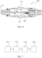
- Fig. 10 shows an impedance limit switch 1000.
- the impedance limit switch has an electronic circuit 900 (electronics unit), which generates an excitation signal for the resonant circuit of the measuring probe 100. Between the measuring electrode 101 and the reference electrode 102, a measuring capacitance forms, which generates a series resonance with a discrete inductance (not shown).
- the amount of the complex impedance of this resonant circuit is analyzed, for example, between 100 MHz and 200 MHz. If a medium (medium) is in the area of the measuring probe, the impedance behavior changes. Exactly this change of the impedance is used for the evaluation. In particular, the minimum of the resonance curve with respect to frequency change and amplitude change is evaluated and from this a switching command is generated.
- the generation of the oscillation frequency is generated by means of a voltage-controlled oscillator (VCO, Voltage Controlled Oscillator). Due to the measuring principle, this oscillation frequency causes EMC radiation in the working area. Measures must be taken to ensure that the EMC radiation in the work area does not exceed the permissible limits. In the following, suitable measures, which preferably do not adversely affect the measurement functionality, are discussed in order to keep the EMC radiation in the working range below the permissible limit values.
- the EMC radiation is reduced by the electronic circuit 900, the transmission voltage (ie the excitation signal for the resonant circuit) adaptive to the Resonance curve of the resonant circuit adapts, with the measurement functionality or sensitivity of the limit switch is not affected as far as possible.
- the amplitude of the resonance frequency can be increased so far that the permissible limit value for the EMC radiation is just kept. As a result, the radiation is reduced and the immunity to radiation (from the outside) maximized.
- the generation of the oscillation frequency of the resonant circuit is performed with the VCO 110 (see. Fig. 9 ), which is controlled via a digital-to-analog converter (DAC) 107 of the microcontroller (processor) 105.
- DAC digital-to-analog converter
- the frequency range from 100 MHz to 200 MHz is to be swept through (swept).
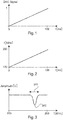
- Fig. 1 shows a typical drive signal from the processor 105 to the DAC 107.
- a set DAC value gives a corresponding VCO voltage, and this in turn gives a VCO output frequency that is fed into the tank circuit 104 (see FIG Fig. 9 ) is fed.
- the signal of the VCO is applied to the resonant circuit 104 of the impedance limit switch.
- the resonance point 301 of the impedance limit switch one obtains in the resonance curve (cf. Fig. 3 ) a low point 302.
- the resonance curve corresponds to an envelope and results from sampling the oscillator signal.
- the resonance curve of the impedance limit switch shown also moves between 100 MHz and 200 MHz and ultimately represents the voltage in the resonant circuit, which is measured at the inductance or the capacitance of the resonant circuit.
- Fig. 4 is a typical EMC radiation shown.
- the horizontal line 402 indicates the allowable limit.
- the EMC radiation 401 exceeds in the region of the resonance peak and in particular in the region of the frequency of the low point 302 (FIG. Fig. 3 ) the limit value 402 of the EMC emission.
- the EMC radiation emitted in Fig. 4 shown must be reduced in the resonance range.
- the transmit voltage (amplitude) is constant and only the frequency is varied. This is in Fig. 5 shown.
- the transmission voltage supplied to the VCO is adjusted according to the measured resonance curve, the EMC radiation in the range of the resonance can be reduced. In the optimal case, one obtains a constant EMC radiation.
- curve 601 of Fig. 6 shows a matched transmission voltage and in Fig. 7 curve 701 shows the corresponding EMC radiation.
- the EMC radiation can be increased (see 701 in Fig. 7 ), so that the limit 402 is still not reached.
- the transmission voltage can be further adapted to achieve optimum.
- a scheme can be constructed which generates a constant level of the output signal or the envelope (resonance curve).
- An example of a corresponding control circuit is in Fig. 9 shown.
- an envelope generator 111 is connected, which measures the voltage across the capacitance of the resonant circuit or the inductance of the resonant circuit and generates therefrom an envelope (resonance curve).
- a control element 109 is provided which compares this envelope with a setpoint input 108 of the microcontroller 105 and forms, for example, the sum or the difference. The result is fed as a control signal (control voltage) into the VCO 110.
- This control signal regulates the signal amplitude of the excitation signal output by the VCO, which is fed into the oscillator circuit 104.
- the signal generated by the unit 109 is delivered to the analog-to-digital converter 106 of the electronic circuit 900, which generates therefrom a digital signal for the microcontroller 105, based on which the microcontroller controls the setpoint input 108.
- This optional additional control signal 112 from the microcontroller 105 to the setpoint specification circuit 108 may be a signal corresponding to the "inverted" envelope of the resonance curve. Since in the region of the resonance peak at constant transmission voltage 113 to the VCO, the EMC radiation is increased, the setpoint specification in this area will be lower.
- the control circuit shown may be set so that the envelope generated by the envelope generator 111 gradually becomes smoother and (in the FIG Ideal case) over the entire frequency range is largely constant, so that the EMC radiation over this frequency range is constant and then can be approximated by a corresponding increase in the transmission voltage 113 to the limit value from below, but without reaching this.
- Fig. 8 shows a circuit diagram of an impedance limit switch without the control of Fig. 9 .
- Fig. 11 shows a flowchart of a method for determining a limit level of a medium.
- step 1101 an excitation signal for a resonant circuit is generated and fed into the resonant circuit.
- This excitation signal is swept in frequency in step 1102, and in step 1103, the resonance curve of the resonant circuit is examined, for example, by sampling the voltage at the inductance or the resonant circuit capacitance.
- step 1104 the voltage of the transmission signal, and thus the voltage of the excitation signal of the resonant circuit, adjusted in response to shape and amplitude of the resonance curve to reduce the EMC emission of the impedance limit switch to keep substantially constant over the entire frequency range and to a limit to approach from below.
Landscapes
- Physics & Mathematics (AREA)
- General Physics & Mathematics (AREA)
- Engineering & Computer Science (AREA)
- Power Engineering (AREA)
- Electromagnetism (AREA)
- Fluid Mechanics (AREA)
- Thermal Sciences (AREA)
- Chemical & Material Sciences (AREA)
- Chemical Kinetics & Catalysis (AREA)
- Analytical Chemistry (AREA)
- Biochemistry (AREA)
- General Health & Medical Sciences (AREA)
- Immunology (AREA)
- Pathology (AREA)
- Life Sciences & Earth Sciences (AREA)
- Health & Medical Sciences (AREA)
- Electrochemistry (AREA)
- Signal Processing (AREA)
- Inductance-Capacitance Distribution Constants And Capacitance-Resistance Oscillators (AREA)
- Measurement Of Levels Of Liquids Or Fluent Solid Materials (AREA)
Abstract
Description
- Die Erfindung betrifft die Grenzstandmessung. Insbesondere betrifft die Erfindung einen Impedanzgrenzschalter, eingerichtet zur Bestimmung eines Grenzstands eines Mediums, ein Verfahren zum Bestimmen eines Grenzstands eines Mediums durch einen Impedanzgrenzschalter, ein Programmelement und ein computerlesbares Medium.
- Grenzstandschalter werden eingesetzt, um einen Grenzstand eines Füllguts in oder außerhalb eines Behälters zu detektieren. Typische Anwendungen für die Erfassung einer solch vordefinierten Füllhöhe sind beispielsweise Prozesstanks, Lagertanks, Silos oder Rohrleitungen in der Prozessindustrie. Grenzstandschalter werden in unterschiedlichsten Flüssigkeiten, sowie granulierten und pulverförmigen Schüttgütern eingesetzt.
- Je nach Eigenschaft des Füllguts sowie den individuellen Prozessbedingungen kommen unterschiedliche Grenzstandschalter zum Einsatz. Bekannt sind beispielsweise Impedanzgrenzschalter, TDR-Melder, Vibrationsgrenzschalter und Sensoren, die nach dem kapazitiven oder resistiven/konduktiven Messprinzip arbeiten.
- Ein vom Grenzstandschalter abgesetzter Schaltbefehl startet oder stoppt Befülleinrichtungen bzw. Entleereinrichtungen, wie Förderbänder oder Pumpen.
- Impedanzgrenzschalter erzeugen ein elektrisches Feld, das in das Innere des Tanks hineinreicht. Die hiermit verbundene EMV-Abstrahlung darf in manchen Anwendungen einen zulässigen Grenzwert nicht überschreiten.
- Es ist eine Aufgabe der Erfindung, einen Impedanzgrenzschalter anzugeben, der in unterschiedlichen Messumgebungen zuverlässig einsetzbar ist.
- Diese Aufgabe wird durch die Merkmale der unabhängigen Patentansprüche gelöst. Weiterbildungen der Erfindung ergeben sich aus den Unteransprüchen und der folgenden Beschreibung.
- Ein erster Aspekt der Erfindung betrifft einen Impedanzgrenzschalter, der zur Bestimmung eines Grenzstandes eines Mediums in einem Behälter eingerichtet ist. Er weist eine Messsonde und eine Elektronikschaltung auf.
- Die Messsonde kann insbesondere eine Messelektrode, eine Bezugselektrode und eine Induktivität aufweisen. Darüber hinaus kann eine Schirmelektrode vorgesehen sein, die dafür sorgt, dass die elektrischen Feldlinien möglichst tief in das Füllgut eindringen.
- Die Elektronikschaltung ist eingerichtet, ein Anregungssignal für einen Schwingkreis, der typischer Weise die Messelektrode, die Bezugselektrode und die Induktivität aufweist, zu erzeugen und in den Schwingkreis einzuspeisen. Des Weiteren ist die Elektronikschaltung eingerichtet, die Frequenz dieses Anregungssignals beispielsweise in Form eines stufenlosen oder gestuften Sweeps durchzufahren und eine Resonanzkurve des Schwingkreises zu bestimmen.
- Darüber hinaus kann die Elektronikschaltung die Amplitude bzw. Spannung des Anregungssignals in Abhängigkeit von der Resonanzkurve anpassen, typischer Weise, indem die Spannung eines Sendesignals, das in einen VCO eingespeist wird, der das Anregungssignal erzeugt, angepasst wird, um die EMV-Abstrahlung des Impedanzgrenzschalters zu reduzieren.
- Ändert sich die Resonanzkurve, hat sich im Regelfall das Anregungssignal geändert, da dieses ja für die Form und die Amplitude der Resonanzkurve verantwortlich ist. Insbesondere kann vorgesehen sein, dass die Amplitude des Anregungssignals, und damit die Spannung des Sendesignals, in Abhängigkeit von der Frequenz variiert wird. Diese Änderung der Amplitude des Anregungssignals bzw. der Spannung des Sendesignals über die Frequenz kann hierbei der Form der Resonanzkurve entsprechen. So führt eine starke Änderung der Amplitude der Resonanzkurve in diesem Fall dazu, dass in diesem Frequenzbereich das Anregungssignal stark geändert wird, und umgekehrt.
- Diese Maßnahmen können dazu führen, dass sich die EMV-Abstrahlung des Impedanzgrenzschalters ohne Verschlechterung oder zumindest ohne deutliche Verschlechterung der Empfindlichkeit der Impedanzmessung reduziert.
- Insbesondere kann eine adaptive Regelung des Anregungssignals (indirekt über die adaptive Regelung der Sendesignalspannung) zur Minimierung der Störabstrahlung vorgesehen sein.
- Gemäß einer Ausführungsform ist die Elektronikschaltung eingerichtet, die Amplitude des Anregungssignals schrittweise über eine Regelschleife anzupassen. Es handelt sich in diesem Fall um ein iteratives, adaptives Verfahren, welches eingesetzt werden kann, um die EMV Abstrahlung möglichst nahe an den Grenzwert anzunähern.
- Gemäß einer Ausführungsform der Erfindung ist die Elektronikschaltung eingerichtet, dafür Sorge zu tragen, dass ein Tiefpunkt in der Resonanzkurve zu einer Verringerung der Amplitude des Anregungssignals bei der Frequenz des Tiefpunkts führt. Diese Überlegung basiert auf der Erkenntnis, dass der Peak in der Resonanzkurve zu einer erhöhten EMV-Abstrahlung führen kann. Wird nun die Frequenz dieses Peaks und seiner Amplitude identifiziert, kann durch eine Verringerung der Amplitude des Anregungssignals im Bereich des Peaks erreicht werden, dass bei diesen Frequenzen die EMV-Abstrahlung abnimmt und, im Idealfall, denselben Wert hat wie in anderen Bereichen der Resonanzkurve.
- Gemäß einer weiteren Ausführungsform der Erfindung ist die Elektronikschaltung eingerichtet, die Amplitude des Anregungssignals derart zu regeln, dass die EMV-Abstrahlung des Impedanzgrenzschalters über den durchgefahrenen Frequenzbereich des Anregungssignals im Wesentlichen konstant ist oder zumindest nur Schwankungen aufweist, die unterhalb eines vorbestimmten Grenzwerts liegen. Es kann vorgesehen sein, dass dieser Grenzwert vom Benutzer eingebbar ist.
- Darüber hinaus kann vorgesehen sein, dass die Elektronikschaltung die Amplitude des Anregungssignals derart regelt, dass die maximale EMV-Abstrahlung des Impedanzgrenzschalters unterhalb eines definierten Grenzwerts liegt. Wie oben kann vorgesehen, dass dieser Grenzwert vom Benutzer eingebbar ist.
- Gemäß einer weiteren Ausführungsform der Erfindung ist die Elektronikschaltung eingerichtet, die Amplitude des Anregungssignals derart zu regeln, dass die EMV-Abstrahlung des Impedanzgrenzschalters nahe bei, aber noch immer unterhalb des definierten Grenzwerts liegt. So kann vorgesehen sein, dass die Regelung nach der Analyse der ersten aufgenommenen Resonanzkurve das Anregungssignal deutlich herabregelt und dann, schrittweise, zumindest abschnittsweise wieder hochregelt, so dass einerseits die Impedanzkurve immer glatter wird (der Peak entwickelt sich zurück) und andererseits sich die Amplitude der Resonanzkurve einem Wert annähert, der dem Grenzwert der zulässigen EMV-Abstrahlung entspricht.
- Vorteilhafter Weise ist der Zusammenhang zwischen Form und Amplitude der Resonanzkurve und der damit zusammenhängenden EMV-Abstrahlung bekannt, so dass das Anregungssignal entsprechend optimal eingestellt werden kann.
- Ein weiterer Aspekt der Erfindung betrifft ein Verfahren zum Bestimmen eines Grenzstands eines Mediums in einem Behälter durch einen Impedanzgrenzschalter. Zunächst wird ein Anregungssignal für einen Schwingkreis des Impedanzgrenzschalters erzeugt. Der Schwingkreis weist typischerweise eine Messelektrode, eine Bezugselektrode und eine Induktivität auf. Danach wird die Frequenz des Anregungssignals durchgefahren (Sweep) und die Resonanzkurve des Schwingkreises wird bestimmt. Danach erfolgt eine Anpassung der Amplitude des Anregungssignals in Abhängigkeit von der Resonanzkurve, insbesondere von der Form und der Amplitude der Resonanzkurve, um eine EMV-Abstrahlung des Impedanzgrenzschalters zu reduzieren und nach Möglichkeit über den gesamten Frequenzbereich des Sweeps möglichst konstant zu halten.
- Ein weiterer Aspekt der Erfindung betrifft ein Programmelement, das, wenn es auf einem Prozessor eines Impedanzgrenzschalters ausgeführt wird, den Impedanzgrenzschalter anweist, das oben und im Folgenden beschriebene Verfahren durchzuführen.
- Ein weiterer Aspekt der Erfindung betrifft ein computerlesbares Medium, auf dem das oben beschriebene Programmelement gespeichert ist.
- Im Folgenden werden unter Bezugnahme auf die Figuren Ausführungsformen der Erfindung beschrieben. Die Darstellungen in den Figuren sind schematisch und nicht maßstäblich. Werden in den folgenden Figuren die gleichen Bezugszeichen verwendet, so bezeichnen diese gleiche oder ähnliche Elemente.
-
-
Fig. 1 zeigt das Ansteuerungssignal einer DAC-Schaltung. -
Fig. 2 zeigt die entsprechende, von einem VCO ausgegebene Frequenz. -
Fig. 3 zeigt eine Resonanzkurve eines Impedanzgrenzschalters. -
Fig. 4 zeigt die EMV-Abstrahlung eines Impedanzgrenzschalters. -
Fig. 5 zeigt ein Anregungssignal (Sendespannung) eines Schwingkreises eines Impedanzgrenzschalters. -
Fig. 6 zeigt weitere Anregungssignale eines Impedanzgrenzschalters. -
Fig. 7 zeigt EMV-Abstrahlungen eines Impedanzgrenzschalters während und nach der erfolgten Regelung des Anregungssignals. -
Fig. 8 zeigt ein Blockschaltbild eines Impedanzgrenzschalters. -
Fig. 9 zeigt ein Blockschaltbild eines weiteren Impedanzgrenzschalters. -
Fig. 10 zeigt einen Impedanzgrenzschalter. -
Fig. 11 zeigt ein Flussdiagramm eines Verfahrens. -
Fig. 10 zeigt einen Impedanzgrenzschalter 1000. Der Impedanzgrenzschalter weist eine Elektronikschaltung 900 (Elektronikeinheit) auf, die ein Anregungssignal für den Schwingkreis der Messsonde 100 erzeugt. Zwischen der Messelektrode 101 und der Bezugselektrode 102 bildet sich eine Messkapazität aus, welche mit einer diskreten Induktivität (nicht dargestellt) eine Serienresonanz erzeugt. - Der Betrag der komplexen Impedanz dieses Schwingkreises wird beispielsweise zwischen 100 MHz und 200 MHz analysiert. Befindet sich ein Füllgut (Medium) im Bereich der Messsonde, so ändert sich das Impedanzverhalten. Genau diese Änderung der Impedanz wird für die Auswertung herangezogen. Im Speziellen wird das Minimum der Resonanzkurve bezüglich Frequenzänderung und Amplitudenänderung ausgewertet und daraus ein Schaltbefehl generiert. Die Erzeugung der Schwingfrequenz wird mit einem spannungsgesteuerten Oszillator (VCO, Voltage Controlled Oscillator) erzeugt. Diese Schwingfrequenz verursacht bedingt durch das Messprinzip eine EMV-Abstrahlung im Arbeitsbereich. Es müssen Maßnahmen ergriffen werden, damit die EMV-Abstrahlung im Arbeitsbereich die zulässigen Grenzwerte nicht überschreitet. Im Folgenden wird auf geeignete Maßnahmen, welche vorzugsweise die Messfunktionalität nicht negativ beeinflussen, eingegangen, um die EMV-Abstrahlung im Arbeitsbereich unter den zulässigen Grenzwerten zu halten.
- Die EMV-Abstrahlung wird reduziert, indem die Elektronikschaltung 900 die Sendespannung (also das Anregungssignal für den Schwingkreis) adaptiv an den Resonanzverlauf des Schwingkreises anpasst, wobei die Messfunktionalität bzw. Empfindlichkeit des Grenzschalters nach Möglichkeit nicht negativ beeinflusst wird.
- Nach der Reduzierung der EMV-Abstrahlung kann die Amplitude der Resonanzfrequenz so weit erhöht werden, dass der zulässige Grenzwert für die EMV-Abstrahlung gerade noch eingehalten wird. Hierdurch wird die Abstrahlung verringert und die Störfestigkeit gegenüber Einstrahlung (von außen) maximiert.
- Ein Kerngedanke kann darin gesehen werden, dass die EMV-Abstrahlung des Impedanzgrenzschalters nach Möglichkeit ohne Verschlechterung der Empfindlichkeit des Messgeräts reduziert wird.
- Die Erzeugung der Schwingfrequenz des Schwingkreises erfolgt mit dem VCO 110 (vgl.
Fig. 9 ), der über einen Digital-Analog-Converter (DAC) 107 des Mikrocontrollers (Prozessor) 105 angesteuert wird. In einer Zeit von beispielsweise 100 ms soll der Frequenzbereich von 100 MHz bis 200 MHz durchgefahren (durchgesweept) werden. -
Fig. 1 zeigt ein typisches Ansteuersignal vom Prozessor 105 an den DAC 107. Das DAC-Signal verläuft linear von beispielsweise t=0 bis t=100 ms von einem Wert 0 bis zu einem Wert 1. - Ein eingestellter DAC-Wert ergibt eine entsprechende VCO-Spannung und diese wiederum eine VCO-Ausgabefrequenz, die in den Schwingkreis 104 (siehe
Fig. 9 ) eingespeist wird. -
Fig. 2 zeigt die VCO-Frequenz, die der VCO ausgibt, wenn er mit dem DAC-Signal derFig. 1 beaufschlagt wird. Auch hier läuft die Zeit von t=0 ms bis t=100 ms. Die Frequenz beginnt beispielsweise bei 100 MHz und läuft bis 200 MHz. - Das Signal des VCO wird auf den Schwingkreis 104 des Impedanzgrenzschalters gegeben. An der Resonanzstelle 301 des Impedanzgrenzschalters erhält man in der Resonanzkurve (vgl.
Fig. 3 ) einen Tiefpunkt 302. Die Resonanzkurve entspricht einer Hüllkurve und ergibt sich durch Abtastung des Schwingkreissignals. - Die in
Fig. 3 gezeigte Resonanzkurve des Impedanzgrenzschalters bewegt sich natürlich ebenfalls zwischen 100 MHz und 200 MHz und stellt letztendlich die Spannung im Schwingkreis dar, die an der Induktivität oder der Kapazität des Schwingkreises gemessen wird. - An der Resonanzstelle ergibt sich eine Anpassung, welche dazu führt, dass die EMV-Abstrahlung an dieser Stelle am höchsten ist, da an diesem Punkt am meisten Energie durch den Schwingkreis fließt.
- In
Fig. 4 ist eine typische EMV-Abstrahlung dargestellt. Die horizontale Linie 402 zeigt den zulässigen Grenzwert an. Die EMV-Abstrahlung 401 übersteigt im Bereich des Resonanzpeaks und insbesondere im Bereich der Frequenz des Tiefpunkts 302 (Fig. 3 ) den Grenzwert 402 der EMV-Abstrahlung. - Die EMV-Abstrahlung, die in
Fig. 4 gezeigt ist, muss im Resonanzbereich reduziert werden. Typischerweise ist die Sendespannung (Amplitude) konstant und es wird lediglich die Frequenz variiert. Dies ist inFig. 5 gezeigt. - Passt man nun die Sendespannung, die dem VCO zugeführt wird, entsprechend der gemessenen Resonanzkurve an, kann die EMV-Abstrahlung im Bereich der Resonanz reduziert werden. Im optimalen Fall erhält man ein konstante EMV-Abstrahlung.
- Die Kurve 601 der
Fig. 6 zeigt eine angepasste Sendespannung und inFig. 7 zeigt die Kurve 701 die entsprechende EMV-Abstrahlung. - Durch die geschilderte Optimierung der Sendespannung (vgl. Kurve 601 der
Fig. 6 ) kann die EMV-Abstrahlung erhöht werden (vgl. 701 inFig. 7 ), so dass aber der Grenzwert 402 noch immer nicht erreicht ist. Somit kann die Sendespannung noch weiter angepasst werden, um ein Optimum zu erreichen. - Basierend auf diesen Überlegungen lässt sich eine Regelung aufbauen, die einen konstanten Pegel des Ausgangssignals bzw. der Hüllkurve (Resonanzkurve) erzeugt. Ein Beispiel für eine entsprechende Regelungsschaltung ist in
Fig. 9 gezeigt. An den Schwingkreis 104 ist ein Hüllkurvengenerator 111 angeschlossen, der die Spannung an der Kapazität des Schwingkreises oder der Induktivität des Schwingkreises misst und daraus eine Hüllkurve (Resonanzkurve) erzeugt. Es ist ein Regelelement 109 vorgesehen, das diese Hüllkurve mit einer Sollwertvorgabe 108 des Mikrocontrollers 105 vergleicht und daraus beispielsweise die Summe oder die Differenz bildet. Das Ergebnis wird als Steuersignal (Steuerspannung) in den VCO 110 eingespeist. Dieses Steuersignal regelt die vom VCO ausgegebene Signalamplitude des Anregungssignals, das in den Schwingkreis 104 eingespeist wird. - Zur gleichen Zeit wird das von der Einheit 109 erzeugte Signal an den Analog-Digital-Converter 106 der Elektronikschaltung 900 abgegeben, die daraus ein digitales Signal für den Mikrocontroller 105 erzeugt, auf Basis dessen der Mikrocontroller die Sollwertvorgabe 108 steuert. Dieses optionale, zusätzliche Steuersignal 112 vom Mikrocontroller 105 an die Sollwertvorgabeschaltung 108 kann ein Signal sein, das der "invertierten" Hüllkurve der Resonanzkurve entspricht. Da im Bereich des Resonanzpeaks bei konstanter Sendespannung 113 an den VCO die EMV-Abstrahlung erhöht ist, wird die Sollwertvorgabe in diesem Bereich geringer sein.
- Die in
Fig. 9 gezeigte Regelungsschaltung kann so eingestellt sein, dass die vom Hüllkurvengenerator 111 erzeugte Hüllkurve schrittweise immer glatter wird und (im Idealfall) über den gesamten Frequenzbereich weitgehend konstant ist, so dass auch die EMV-Abstrahlung über diesen Frequenzbereich konstant ist und dann über eine entsprechende Erhöhung der Sendespannung 113 an den Grenzwert von unten angenähert werden kann, ohne diesen jedoch zu erreichen. -
Fig. 8 zeigt ein Schaltbild eines Impedanzgrenzstandschalters ohne die Regelung derFig. 9 . -
Fig. 11 zeigt ein Flussdiagramm eines Verfahrens zur Bestimmung eines Grenzstands eines Mediums. In Schritt 1101 wird ein Anregungssignal für einen Schwingkreis erzeugt und in den Schwingkreis eingespeist. Dieses Anregungssignal wird in Schritt 1102 in der Frequenz durchgefahren und in Schritt 1103 wird die Resonanzkurve des Schwingkreises untersucht, beispielsweise indem die Spannung an der Induktivität oder der Schwingkreiskapazität abgetastet wird. - In Schritt 1104 wird die Spannung des Sendesignals, und damit die Spannung des Anregungssignals des Schwingkreises, in Abhängigkeit von Form und Amplitude der Resonanzkurve angepasst, um die EMV-Abstrahlung des Impedanzgrenzschalters zu reduzieren, über den gesamten Frequenzbereich weitgehend konstant zu halten und an einen Grenzwert von unten her anzunähern.
- Ergänzend sei daraufhingewiesen, dass "umfassend" und "aufweisend" keine anderen Elemente oder Schritte ausschließt und "eine" oder "ein" keine Vielzahl ausschließt. Ferner sei daraufhingewiesen, dass Merkmale oder Schritte, die mit Verweis auf eines der obigen Ausführungsbeispiele beschrieben worden sind, auch in Kombination mit anderen Merkmalen oder Schritten anderer oben beschriebener Ausführungsbeispiele verwendet werden können. Bezugszeichen in den Ansprüchen sind nicht als Einschränkungen zu sehen.
Claims (10)
- Impedanzgrenzschalter (1000), eingerichtet zur Bestimmung eines Grenzstands eines Mediums, aufweisend:eine Messsonde (100) mit einem Schwingkreis (104);eine Elektronikschaltung (900), eingerichtet zur Erzeugung eines Anregungssignals für den Schwingkreis (104);wobei die Elektronikschaltung weiter eingerichtet ist, die Frequenz des Anregungssignals durchzufahren und eine Resonanzkurve des Schwingkreises zu bestimmen;wobei die Elektronikschaltung weiter eingerichtet ist, die Amplitude des Anregungssignals in Abhängigkeit von der Resonanzkurve anzupassen, um eine EMV Abstrahlung des Impedanzgrenzschalters zu reduzieren.
- Impedanzgrenzschalter nach Anspruch 1,wobei die Elektronikschaltung (900) eingerichtet ist, die Amplitude des Anregungssignals entsprechend der Resonanzkurve anzupassen.
- Impedanzgrenzschalter nach Anspruch 1 oder 2,wobei die Elektronikschaltung (900) eingerichtet ist, die Amplitude des Anregungssignals schrittweise über eine Regelschleife anzupassen.
- Impedanzgrenzschalter nach einem der vorhergehenden Ansprüche,wobei die Elektronikschaltung (900) eingerichtet ist, dafür zu sorgen, dass ein Tiefpunkt in der Resonanzkurve zu einer Verringerung der Amplitude des Anregungssignals bei der Frequenz des Tiefpunkts führt.
- Impedanzgrenzschalter nach einem der vorhergehenden Ansprüche,wobei die Elektronikschaltung (900) eingerichtet ist, die Amplitude des Anregungssignals derart zu regeln, dass die EMV Abstrahlung des Impedanzgrenzschalters über den durchgefahrenen Frequenzbereich des Anregungssignals konstant ist.
- Impedanzgrenzschalter nach einem der vorhergehenden Ansprüche,wobei die Elektronikschaltung (900) eingerichtet ist, die Amplitude des Anregungssignals derart zu regeln, dass die EMV Abstrahlung des Impedanzgrenzschalters unterhalb eines definierten Grenzwertes liegt.
- Impedanzgrenzschalter nach einem der vorhergehenden Ansprüche,wobei die Elektronikschaltung (900) eingerichtet ist, die Amplitude des Anregungssignals derart zu regeln, dass die EMV Abstrahlung des Impedanzgrenzschalters nahe bei aber noch immer unterhalb eines definierten Grenzwertes liegt.
- Verfahren zum Bestimmen eines Grenzstands eines Mediums durch einen Impedanzgrenzschalter (1000), aufweisend die folgenden Schritte:Erzeugen eines Anregungssignals für einen Schwingkreis (104);Durchfahren der Frequenz des Anregungssignals;Bestimmen einer Resonanzkurve des Schwingkreises;Anpassen der Amplitude des Anregungssignals in Abhängigkeit von der Resonanzkurve, um eine EMV Abstrahlung des Impedanzgrenzschalters zu reduzieren.
- Programmelement, das, wenn es auf einem Prozessor (105) eines Impedanzgrenzschalters (1000) ausgeführt wird, den Impedanzgrenzschalter anweist, die folgenden Schritte durchzuführen:Erzeugen eines Anregungssignals für einen Schwingkreis (104);Durchfahren der Frequenz des Anregungssignals;Bestimmen einer Resonanzkurve des Schwingkreises;Anpassen der Amplitude des Anregungssignals in Abhängigkeit von der Resonanzkurve, um eine EMV Abstrahlung des Impedanzgrenzschalters zu reduzieren.
- Computerlesbares Medium, auf dem ein Programmelement nach Anspruch 9 gespeichert ist.
Priority Applications (4)
| Application Number | Priority Date | Filing Date | Title |
|---|---|---|---|
| EP18163330.6A EP3543660B1 (de) | 2018-03-22 | 2018-03-22 | Impedanzgrenzschalter zur reduzierung der emv-abstrahlung und verfahren zum bestimmen eines grenzstands eines mediums durch einen impedanzgrenzschalter |
| HUE18163330A HUE051101T2 (hu) | 2018-03-22 | 2018-03-22 | Impedancia-határértékkapcsoló EMC sugárzás csökkentésére és eljárás egy közeg határértékének meghatározására egy impedancia-határértékkapcsolóval |
| US16/351,838 US11353355B2 (en) | 2018-03-22 | 2019-03-13 | Impedance limit switch for reducing EMC radiation |
| CN201910215901.5A CN110296749B (zh) | 2018-03-22 | 2019-03-21 | 阻抗限位开关、介质极限物位确定方法及计算机可读介质 |
Applications Claiming Priority (1)
| Application Number | Priority Date | Filing Date | Title |
|---|---|---|---|
| EP18163330.6A EP3543660B1 (de) | 2018-03-22 | 2018-03-22 | Impedanzgrenzschalter zur reduzierung der emv-abstrahlung und verfahren zum bestimmen eines grenzstands eines mediums durch einen impedanzgrenzschalter |
Publications (2)
| Publication Number | Publication Date |
|---|---|
| EP3543660A1 true EP3543660A1 (de) | 2019-09-25 |
| EP3543660B1 EP3543660B1 (de) | 2020-04-15 |
Family
ID=61750033
Family Applications (1)
| Application Number | Title | Priority Date | Filing Date |
|---|---|---|---|
| EP18163330.6A Active EP3543660B1 (de) | 2018-03-22 | 2018-03-22 | Impedanzgrenzschalter zur reduzierung der emv-abstrahlung und verfahren zum bestimmen eines grenzstands eines mediums durch einen impedanzgrenzschalter |
Country Status (4)
| Country | Link |
|---|---|
| US (1) | US11353355B2 (de) |
| EP (1) | EP3543660B1 (de) |
| CN (1) | CN110296749B (de) |
| HU (1) | HUE051101T2 (de) |
Families Citing this family (1)
| Publication number | Priority date | Publication date | Assignee | Title |
|---|---|---|---|---|
| EP4058816B1 (de) * | 2019-11-13 | 2025-02-26 | Phoenix Contact GmbH & Co. KG | Kontaktüberwachungsvorrichtung |
Citations (3)
| Publication number | Priority date | Publication date | Assignee | Title |
|---|---|---|---|---|
| EP0881475A1 (de) * | 1997-05-26 | 1998-12-02 | Canon Kabushiki Kaisha | Vorrichtung zur Bestimmung der Menge eines Verbrauchsprodukts in einem Behälter und entsprechende Vorrichtung zum Drucken von Dokumenten |
| DE102009060742A1 (de) * | 2009-12-30 | 2011-07-07 | NEGELE Messtechnik GmbH, 87743 | Einrichtung zum Erkennen eines Pegelstandes |
| EP3118591A1 (de) * | 2015-07-15 | 2017-01-18 | VEGA Grieshaber KG | Füllstandmessgerät |
Family Cites Families (13)
| Publication number | Priority date | Publication date | Assignee | Title |
|---|---|---|---|---|
| US5083470A (en) * | 1990-01-18 | 1992-01-28 | E. I. Du Pont De Nemours And Company | Capacitive liquid level sensor |
| US20030206021A1 (en) * | 1997-07-25 | 2003-11-06 | Laletin William H. | Method and apparatus for measuring and analyzing electrical or electrochemical systems |
| DE10158584A1 (de) | 2001-11-29 | 2003-07-03 | Philips Intellectual Property | Piezoelektrische Antriebsvorrichtung und ein Regelverfahren für eine piezoelektrische Antriebsvorrichtung |
| CN101611294B (zh) | 2007-01-16 | 2012-10-03 | 恩德莱斯和豪瑟尔两合公司 | 用于确定和/或者监测介质过程变量的装置 |
| DE102009002674A1 (de) | 2009-04-27 | 2010-10-28 | Ifm Electronic Gmbh | Admittanzmeßvorrichtung zur Überwachung eines Mediums |
| CN101834473B (zh) | 2010-05-21 | 2012-05-09 | 西安电子科技大学 | 谐振跟踪式非接触供电装置及供电方法 |
| GB2495104A (en) * | 2011-09-28 | 2013-04-03 | Oxford Rf Sensors Ltd | Rotor blade sensor |
| CN105486893B (zh) | 2014-09-19 | 2019-06-21 | 国家电网公司 | 振荡波产生装置 |
| DE102015101891A1 (de) | 2015-02-10 | 2016-08-11 | Endress + Hauser Gmbh + Co. Kg | Vorrichtung zur Bestimmung und/oder Überwachung zumindest einer Prozessgröße eines Mediums |
| US9612433B2 (en) | 2015-05-21 | 2017-04-04 | Microvision, Inc. | Resonant system excitation power reduction using dynamic phase offset |
| EP3521777B1 (de) * | 2018-02-06 | 2021-05-19 | VEGA Grieshaber KG | Impedanzsensor und verfahren zu dessen betrieb |
| DE102018111960B4 (de) * | 2018-05-17 | 2025-10-23 | Vega Grieshaber Kg | Impedanzgrenzstandsensor |
| HUE051109T2 (hu) * | 2018-07-30 | 2021-03-01 | Grieshaber Vega Kg | Impedancia érzékelõ és eljárás impedancia érzékelõ kapcsolási állapotának meghatározására |
-
2018
- 2018-03-22 HU HUE18163330A patent/HUE051101T2/hu unknown
- 2018-03-22 EP EP18163330.6A patent/EP3543660B1/de active Active
-
2019
- 2019-03-13 US US16/351,838 patent/US11353355B2/en active Active
- 2019-03-21 CN CN201910215901.5A patent/CN110296749B/zh active Active
Patent Citations (3)
| Publication number | Priority date | Publication date | Assignee | Title |
|---|---|---|---|---|
| EP0881475A1 (de) * | 1997-05-26 | 1998-12-02 | Canon Kabushiki Kaisha | Vorrichtung zur Bestimmung der Menge eines Verbrauchsprodukts in einem Behälter und entsprechende Vorrichtung zum Drucken von Dokumenten |
| DE102009060742A1 (de) * | 2009-12-30 | 2011-07-07 | NEGELE Messtechnik GmbH, 87743 | Einrichtung zum Erkennen eines Pegelstandes |
| EP3118591A1 (de) * | 2015-07-15 | 2017-01-18 | VEGA Grieshaber KG | Füllstandmessgerät |
Also Published As
| Publication number | Publication date |
|---|---|
| US20190293471A1 (en) | 2019-09-26 |
| CN110296749B (zh) | 2021-11-30 |
| US11353355B2 (en) | 2022-06-07 |
| EP3543660B1 (de) | 2020-04-15 |
| HUE051101T2 (hu) | 2021-03-01 |
| CN110296749A (zh) | 2019-10-01 |
Similar Documents
| Publication | Publication Date | Title |
|---|---|---|
| EP2737287B1 (de) | Verfahren zur berechnung der schwingungsamplitude einer sonotrode | |
| DE4405238A1 (de) | Verfahren und Anordnung zur Messung des Füllstands in einem Behälter | |
| EP3312571B1 (de) | Impedanzgrenzschalter mit zusätzlicher schirmelektrode | |
| DE102011003158A1 (de) | Vorrichtung und Verfahren zur kapazitiven Füllstandsmessung | |
| DE102011055693A1 (de) | Radargerät und Verfahren zur Erkennung eines Ausfalls eines Empfangskanals eines Radargerätes | |
| WO2004034003A1 (de) | Vibrations-füllstandssensor | |
| DE2827032A1 (de) | Detektorschaltung | |
| EP1221026A1 (de) | Verfahren zur erhöhung der störfestigkeit eines zeitbereichsreflektometers und schaltungsanordnung zur durchführung der verfahren | |
| WO2002045045A1 (de) | Elektronische messvorrichtung zur erfassung einer prozesswvariablen, und verfahren zum betreiben einer solchen messvorrichtung | |
| EP3513152B1 (de) | Kompensation einer phasenverschiebung zumindest einer komponente einer elektronik eines vibronischen sensors | |
| EP3153829B1 (de) | Verfahren und vorrichtung zur grenzstandbestimmung | |
| EP3174644A1 (de) | Vorrichtung zum ultraschallbearbeiten von materialien mit triggereinrichtung | |
| EP2798317B1 (de) | Vorrichtung zur bestimmung und/oder überwachung eines grenzwertes einer prozessgrösse | |
| DE102008027921B4 (de) | Admittanzmeßvorrichtung für einen Füllstandsensor | |
| EP2634921B1 (de) | Annäherungssensor und Verfahren zum Bestimmen der Annäherung an einen elektrisch leitfähigen Körper | |
| EP3521777B1 (de) | Impedanzsensor und verfahren zu dessen betrieb | |
| EP3543660B1 (de) | Impedanzgrenzschalter zur reduzierung der emv-abstrahlung und verfahren zum bestimmen eines grenzstands eines mediums durch einen impedanzgrenzschalter | |
| EP3811039A1 (de) | Füllstandssensor oder grenzstandsensor mit temperaturkompensation | |
| DE112014007006T5 (de) | Einstellschaltung und Verfahren zur Messung optischer Parameter und optisches Messsystem | |
| DE19935646A1 (de) | Vorrichtung zur Bestimmung des Füllstandes eines Füllguts in einem Behälter | |
| DE102014113545A1 (de) | Vorrichtung und Verfahren zur Überwachung einer Prozessgröße eines Mediums | |
| DE10328113B4 (de) | Vorrichtung zum Betreiben einer schwingfähigen Einheit eines Vibrationsresonators | |
| EP4004567A1 (de) | Verfahren und generator zur charakterisierung eines schwingsystems | |
| EP0985917B1 (de) | Verfahren zum Betreiben und Funktionstesten eines Vibrationsgrenzstandsensors und hierfür geeigneter Vibrationsgrenzstandsensor | |
| DE3720473A1 (de) | Kapazitive fuellstandsmessung |
Legal Events
| Date | Code | Title | Description |
|---|---|---|---|
| PUAI | Public reference made under article 153(3) epc to a published international application that has entered the european phase |
Free format text: ORIGINAL CODE: 0009012 |
|
| STAA | Information on the status of an ep patent application or granted ep patent |
Free format text: STATUS: REQUEST FOR EXAMINATION WAS MADE |
|
| 17P | Request for examination filed |
Effective date: 20181218 |
|
| AK | Designated contracting states |
Kind code of ref document: A1 Designated state(s): AL AT BE BG CH CY CZ DE DK EE ES FI FR GB GR HR HU IE IS IT LI LT LU LV MC MK MT NL NO PL PT RO RS SE SI SK SM TR |
|
| AX | Request for extension of the european patent |
Extension state: BA ME |
|
| GRAP | Despatch of communication of intention to grant a patent |
Free format text: ORIGINAL CODE: EPIDOSNIGR1 |
|
| STAA | Information on the status of an ep patent application or granted ep patent |
Free format text: STATUS: GRANT OF PATENT IS INTENDED |
|
| INTG | Intention to grant announced |
Effective date: 20191127 |
|
| GRAS | Grant fee paid |
Free format text: ORIGINAL CODE: EPIDOSNIGR3 |
|
| GRAA | (expected) grant |
Free format text: ORIGINAL CODE: 0009210 |
|
| STAA | Information on the status of an ep patent application or granted ep patent |
Free format text: STATUS: THE PATENT HAS BEEN GRANTED |
|
| AK | Designated contracting states |
Kind code of ref document: B1 Designated state(s): AL AT BE BG CH CY CZ DE DK EE ES FI FR GB GR HR HU IE IS IT LI LT LU LV MC MK MT NL NO PL PT RO RS SE SI SK SM TR |
|
| REG | Reference to a national code |
Ref country code: CH Ref legal event code: EP |
|
| REG | Reference to a national code |
Ref country code: DE Ref legal event code: R096 Ref document number: 502018001178 Country of ref document: DE |
|
| REG | Reference to a national code |
Ref country code: IE Ref legal event code: FG4D Free format text: LANGUAGE OF EP DOCUMENT: GERMAN |
|
| REG | Reference to a national code |
Ref country code: AT Ref legal event code: REF Ref document number: 1257867 Country of ref document: AT Kind code of ref document: T Effective date: 20200515 |
|
| REG | Reference to a national code |
Ref country code: NL Ref legal event code: MP Effective date: 20200415 |
|
| REG | Reference to a national code |
Ref country code: LT Ref legal event code: MG4D |
|
| PG25 | Lapsed in a contracting state [announced via postgrant information from national office to epo] |
Ref country code: PT Free format text: LAPSE BECAUSE OF FAILURE TO SUBMIT A TRANSLATION OF THE DESCRIPTION OR TO PAY THE FEE WITHIN THE PRESCRIBED TIME-LIMIT Effective date: 20200817 Ref country code: NL Free format text: LAPSE BECAUSE OF FAILURE TO SUBMIT A TRANSLATION OF THE DESCRIPTION OR TO PAY THE FEE WITHIN THE PRESCRIBED TIME-LIMIT Effective date: 20200415 Ref country code: LT Free format text: LAPSE BECAUSE OF FAILURE TO SUBMIT A TRANSLATION OF THE DESCRIPTION OR TO PAY THE FEE WITHIN THE PRESCRIBED TIME-LIMIT Effective date: 20200415 Ref country code: GR Free format text: LAPSE BECAUSE OF FAILURE TO SUBMIT A TRANSLATION OF THE DESCRIPTION OR TO PAY THE FEE WITHIN THE PRESCRIBED TIME-LIMIT Effective date: 20200716 Ref country code: FI Free format text: LAPSE BECAUSE OF FAILURE TO SUBMIT A TRANSLATION OF THE DESCRIPTION OR TO PAY THE FEE WITHIN THE PRESCRIBED TIME-LIMIT Effective date: 20200415 Ref country code: NO Free format text: LAPSE BECAUSE OF FAILURE TO SUBMIT A TRANSLATION OF THE DESCRIPTION OR TO PAY THE FEE WITHIN THE PRESCRIBED TIME-LIMIT Effective date: 20200715 Ref country code: IS Free format text: LAPSE BECAUSE OF FAILURE TO SUBMIT A TRANSLATION OF THE DESCRIPTION OR TO PAY THE FEE WITHIN THE PRESCRIBED TIME-LIMIT Effective date: 20200815 Ref country code: SE Free format text: LAPSE BECAUSE OF FAILURE TO SUBMIT A TRANSLATION OF THE DESCRIPTION OR TO PAY THE FEE WITHIN THE PRESCRIBED TIME-LIMIT Effective date: 20200415 |
|
| PG25 | Lapsed in a contracting state [announced via postgrant information from national office to epo] |
Ref country code: BG Free format text: LAPSE BECAUSE OF FAILURE TO SUBMIT A TRANSLATION OF THE DESCRIPTION OR TO PAY THE FEE WITHIN THE PRESCRIBED TIME-LIMIT Effective date: 20200715 Ref country code: RS Free format text: LAPSE BECAUSE OF FAILURE TO SUBMIT A TRANSLATION OF THE DESCRIPTION OR TO PAY THE FEE WITHIN THE PRESCRIBED TIME-LIMIT Effective date: 20200415 Ref country code: HR Free format text: LAPSE BECAUSE OF FAILURE TO SUBMIT A TRANSLATION OF THE DESCRIPTION OR TO PAY THE FEE WITHIN THE PRESCRIBED TIME-LIMIT Effective date: 20200415 Ref country code: LV Free format text: LAPSE BECAUSE OF FAILURE TO SUBMIT A TRANSLATION OF THE DESCRIPTION OR TO PAY THE FEE WITHIN THE PRESCRIBED TIME-LIMIT Effective date: 20200415 |
|
| PG25 | Lapsed in a contracting state [announced via postgrant information from national office to epo] |
Ref country code: AL Free format text: LAPSE BECAUSE OF FAILURE TO SUBMIT A TRANSLATION OF THE DESCRIPTION OR TO PAY THE FEE WITHIN THE PRESCRIBED TIME-LIMIT Effective date: 20200415 |
|
| REG | Reference to a national code |
Ref country code: DE Ref legal event code: R097 Ref document number: 502018001178 Country of ref document: DE |
|
| PG25 | Lapsed in a contracting state [announced via postgrant information from national office to epo] |
Ref country code: DK Free format text: LAPSE BECAUSE OF FAILURE TO SUBMIT A TRANSLATION OF THE DESCRIPTION OR TO PAY THE FEE WITHIN THE PRESCRIBED TIME-LIMIT Effective date: 20200415 Ref country code: EE Free format text: LAPSE BECAUSE OF FAILURE TO SUBMIT A TRANSLATION OF THE DESCRIPTION OR TO PAY THE FEE WITHIN THE PRESCRIBED TIME-LIMIT Effective date: 20200415 Ref country code: SM Free format text: LAPSE BECAUSE OF FAILURE TO SUBMIT A TRANSLATION OF THE DESCRIPTION OR TO PAY THE FEE WITHIN THE PRESCRIBED TIME-LIMIT Effective date: 20200415 Ref country code: ES Free format text: LAPSE BECAUSE OF FAILURE TO SUBMIT A TRANSLATION OF THE DESCRIPTION OR TO PAY THE FEE WITHIN THE PRESCRIBED TIME-LIMIT Effective date: 20200415 Ref country code: CZ Free format text: LAPSE BECAUSE OF FAILURE TO SUBMIT A TRANSLATION OF THE DESCRIPTION OR TO PAY THE FEE WITHIN THE PRESCRIBED TIME-LIMIT Effective date: 20200415 Ref country code: RO Free format text: LAPSE BECAUSE OF FAILURE TO SUBMIT A TRANSLATION OF THE DESCRIPTION OR TO PAY THE FEE WITHIN THE PRESCRIBED TIME-LIMIT Effective date: 20200415 Ref country code: IT Free format text: LAPSE BECAUSE OF FAILURE TO SUBMIT A TRANSLATION OF THE DESCRIPTION OR TO PAY THE FEE WITHIN THE PRESCRIBED TIME-LIMIT Effective date: 20200415 |
|
| PLBE | No opposition filed within time limit |
Free format text: ORIGINAL CODE: 0009261 |
|
| STAA | Information on the status of an ep patent application or granted ep patent |
Free format text: STATUS: NO OPPOSITION FILED WITHIN TIME LIMIT |
|
| PG25 | Lapsed in a contracting state [announced via postgrant information from national office to epo] |
Ref country code: SK Free format text: LAPSE BECAUSE OF FAILURE TO SUBMIT A TRANSLATION OF THE DESCRIPTION OR TO PAY THE FEE WITHIN THE PRESCRIBED TIME-LIMIT Effective date: 20200415 Ref country code: PL Free format text: LAPSE BECAUSE OF FAILURE TO SUBMIT A TRANSLATION OF THE DESCRIPTION OR TO PAY THE FEE WITHIN THE PRESCRIBED TIME-LIMIT Effective date: 20200415 |
|
| REG | Reference to a national code |
Ref country code: HU Ref legal event code: AG4A Ref document number: E051101 Country of ref document: HU |
|
| REG | Reference to a national code |
Ref country code: CH Ref legal event code: NV Representative=s name: VALIPAT S.A. C/O BOVARD SA NEUCHATEL, CH |
|
| 26N | No opposition filed |
Effective date: 20210118 |
|
| PG25 | Lapsed in a contracting state [announced via postgrant information from national office to epo] |
Ref country code: MC Free format text: LAPSE BECAUSE OF FAILURE TO SUBMIT A TRANSLATION OF THE DESCRIPTION OR TO PAY THE FEE WITHIN THE PRESCRIBED TIME-LIMIT Effective date: 20200415 |
|
| REG | Reference to a national code |
Ref country code: BE Ref legal event code: MM Effective date: 20210331 |
|
| PG25 | Lapsed in a contracting state [announced via postgrant information from national office to epo] |
Ref country code: LU Free format text: LAPSE BECAUSE OF NON-PAYMENT OF DUE FEES Effective date: 20210322 Ref country code: IE Free format text: LAPSE BECAUSE OF NON-PAYMENT OF DUE FEES Effective date: 20210322 Ref country code: FR Free format text: LAPSE BECAUSE OF NON-PAYMENT OF DUE FEES Effective date: 20210331 |
|
| PG25 | Lapsed in a contracting state [announced via postgrant information from national office to epo] |
Ref country code: BE Free format text: LAPSE BECAUSE OF NON-PAYMENT OF DUE FEES Effective date: 20210331 |
|
| GBPC | Gb: european patent ceased through non-payment of renewal fee |
Effective date: 20220322 |
|
| PG25 | Lapsed in a contracting state [announced via postgrant information from national office to epo] |
Ref country code: GB Free format text: LAPSE BECAUSE OF NON-PAYMENT OF DUE FEES Effective date: 20220322 |
|
| P01 | Opt-out of the competence of the unified patent court (upc) registered |
Effective date: 20230524 |
|
| PG25 | Lapsed in a contracting state [announced via postgrant information from national office to epo] |
Ref country code: CY Free format text: LAPSE BECAUSE OF FAILURE TO SUBMIT A TRANSLATION OF THE DESCRIPTION OR TO PAY THE FEE WITHIN THE PRESCRIBED TIME-LIMIT Effective date: 20200415 |
|
| PG25 | Lapsed in a contracting state [announced via postgrant information from national office to epo] |
Ref country code: SI Free format text: LAPSE BECAUSE OF FAILURE TO SUBMIT A TRANSLATION OF THE DESCRIPTION OR TO PAY THE FEE WITHIN THE PRESCRIBED TIME-LIMIT Effective date: 20200415 |
|
| PG25 | Lapsed in a contracting state [announced via postgrant information from national office to epo] |
Ref country code: MK Free format text: LAPSE BECAUSE OF FAILURE TO SUBMIT A TRANSLATION OF THE DESCRIPTION OR TO PAY THE FEE WITHIN THE PRESCRIBED TIME-LIMIT Effective date: 20200415 |
|
| REG | Reference to a national code |
Ref country code: AT Ref legal event code: MM01 Ref document number: 1257867 Country of ref document: AT Kind code of ref document: T Effective date: 20230322 |
|
| PG25 | Lapsed in a contracting state [announced via postgrant information from national office to epo] |
Ref country code: AT Free format text: LAPSE BECAUSE OF NON-PAYMENT OF DUE FEES Effective date: 20230322 |
|
| PG25 | Lapsed in a contracting state [announced via postgrant information from national office to epo] |
Ref country code: AT Free format text: LAPSE BECAUSE OF NON-PAYMENT OF DUE FEES Effective date: 20230322 |
|
| PG25 | Lapsed in a contracting state [announced via postgrant information from national office to epo] |
Ref country code: MT Free format text: LAPSE BECAUSE OF FAILURE TO SUBMIT A TRANSLATION OF THE DESCRIPTION OR TO PAY THE FEE WITHIN THE PRESCRIBED TIME-LIMIT Effective date: 20200415 |
|
| PGFP | Annual fee paid to national office [announced via postgrant information from national office to epo] |
Ref country code: CH Payment date: 20250401 Year of fee payment: 8 |
|
| PG25 | Lapsed in a contracting state [announced via postgrant information from national office to epo] |
Ref country code: TR Free format text: LAPSE BECAUSE OF FAILURE TO SUBMIT A TRANSLATION OF THE DESCRIPTION OR TO PAY THE FEE WITHIN THE PRESCRIBED TIME-LIMIT Effective date: 20200415 |
|
| REG | Reference to a national code |
Ref country code: CH Ref legal event code: U11 Free format text: ST27 STATUS EVENT CODE: U-0-0-U10-U11 (AS PROVIDED BY THE NATIONAL OFFICE) Effective date: 20260401 |
|
| PGFP | Annual fee paid to national office [announced via postgrant information from national office to epo] |
Ref country code: DE Payment date: 20260320 Year of fee payment: 9 |
|
| PGFP | Annual fee paid to national office [announced via postgrant information from national office to epo] |
Ref country code: AT Payment date: 20260410 Year of fee payment: 5 |
|
| PGFP | Annual fee paid to national office [announced via postgrant information from national office to epo] |
Ref country code: HU Payment date: 20260313 Year of fee payment: 9 |