EP3543477A1 - Hooded entrance to effusion holes - Google Patents
Hooded entrance to effusion holes Download PDFInfo
- Publication number
- EP3543477A1 EP3543477A1 EP19163888.1A EP19163888A EP3543477A1 EP 3543477 A1 EP3543477 A1 EP 3543477A1 EP 19163888 A EP19163888 A EP 19163888A EP 3543477 A1 EP3543477 A1 EP 3543477A1
- Authority
- EP
- European Patent Office
- Prior art keywords
- component
- heat shield
- combustor
- gas turbine
- shield panel
- Prior art date
- Legal status (The legal status is an assumption and is not a legal conclusion. Google has not performed a legal analysis and makes no representation as to the accuracy of the status listed.)
- Granted
Links
Images



Classifications
-
- F—MECHANICAL ENGINEERING; LIGHTING; HEATING; WEAPONS; BLASTING
- F23—COMBUSTION APPARATUS; COMBUSTION PROCESSES
- F23R—GENERATING COMBUSTION PRODUCTS OF HIGH PRESSURE OR HIGH VELOCITY, e.g. GAS-TURBINE COMBUSTION CHAMBERS
- F23R3/00—Continuous combustion chambers using liquid or gaseous fuel
- F23R3/002—Wall structures
-
- F—MECHANICAL ENGINEERING; LIGHTING; HEATING; WEAPONS; BLASTING
- F01—MACHINES OR ENGINES IN GENERAL; ENGINE PLANTS IN GENERAL; STEAM ENGINES
- F01D—NON-POSITIVE DISPLACEMENT MACHINES OR ENGINES, e.g. STEAM TURBINES
- F01D25/00—Component parts, details, or accessories, not provided for in, or of interest apart from, other groups
- F01D25/08—Cooling; Heating; Heat-insulation
- F01D25/12—Cooling
-
- F—MECHANICAL ENGINEERING; LIGHTING; HEATING; WEAPONS; BLASTING
- F23—COMBUSTION APPARATUS; COMBUSTION PROCESSES
- F23R—GENERATING COMBUSTION PRODUCTS OF HIGH PRESSURE OR HIGH VELOCITY, e.g. GAS-TURBINE COMBUSTION CHAMBERS
- F23R3/00—Continuous combustion chambers using liquid or gaseous fuel
- F23R3/02—Continuous combustion chambers using liquid or gaseous fuel characterised by the air-flow or gas-flow configuration
- F23R3/04—Air inlet arrangements
- F23R3/06—Arrangement of apertures along the flame tube
-
- F—MECHANICAL ENGINEERING; LIGHTING; HEATING; WEAPONS; BLASTING
- F05—INDEXING SCHEMES RELATING TO ENGINES OR PUMPS IN VARIOUS SUBCLASSES OF CLASSES F01-F04
- F05D—INDEXING SCHEME FOR ASPECTS RELATING TO NON-POSITIVE-DISPLACEMENT MACHINES OR ENGINES, GAS-TURBINES OR JET-PROPULSION PLANTS
- F05D2250/00—Geometry
- F05D2250/50—Inlet or outlet
- F05D2250/51—Inlet
-
- F—MECHANICAL ENGINEERING; LIGHTING; HEATING; WEAPONS; BLASTING
- F05—INDEXING SCHEMES RELATING TO ENGINES OR PUMPS IN VARIOUS SUBCLASSES OF CLASSES F01-F04
- F05D—INDEXING SCHEME FOR ASPECTS RELATING TO NON-POSITIVE-DISPLACEMENT MACHINES OR ENGINES, GAS-TURBINES OR JET-PROPULSION PLANTS
- F05D2260/00—Function
- F05D2260/20—Heat transfer, e.g. cooling
- F05D2260/201—Heat transfer, e.g. cooling by impingement of a fluid
-
- F—MECHANICAL ENGINEERING; LIGHTING; HEATING; WEAPONS; BLASTING
- F23—COMBUSTION APPARATUS; COMBUSTION PROCESSES
- F23R—GENERATING COMBUSTION PRODUCTS OF HIGH PRESSURE OR HIGH VELOCITY, e.g. GAS-TURBINE COMBUSTION CHAMBERS
- F23R2900/00—Special features of, or arrangements for continuous combustion chambers; Combustion processes therefor
- F23R2900/03041—Effusion cooled combustion chamber walls or domes
-
- F—MECHANICAL ENGINEERING; LIGHTING; HEATING; WEAPONS; BLASTING
- F23—COMBUSTION APPARATUS; COMBUSTION PROCESSES
- F23R—GENERATING COMBUSTION PRODUCTS OF HIGH PRESSURE OR HIGH VELOCITY, e.g. GAS-TURBINE COMBUSTION CHAMBERS
- F23R2900/00—Special features of, or arrangements for continuous combustion chambers; Combustion processes therefor
- F23R2900/03044—Impingement cooled combustion chamber walls or subassemblies
-
- Y—GENERAL TAGGING OF NEW TECHNOLOGICAL DEVELOPMENTS; GENERAL TAGGING OF CROSS-SECTIONAL TECHNOLOGIES SPANNING OVER SEVERAL SECTIONS OF THE IPC; TECHNICAL SUBJECTS COVERED BY FORMER USPC CROSS-REFERENCE ART COLLECTIONS [XRACs] AND DIGESTS
- Y02—TECHNOLOGIES OR APPLICATIONS FOR MITIGATION OR ADAPTATION AGAINST CLIMATE CHANGE
- Y02T—CLIMATE CHANGE MITIGATION TECHNOLOGIES RELATED TO TRANSPORTATION
- Y02T50/00—Aeronautics or air transport
- Y02T50/60—Efficient propulsion technologies, e.g. for aircraft
Definitions
- the subject matter disclosed herein generally relates to gas turbine engines and, more particularly, to a method and apparatus to cooling surfaces of components of gas turbine engines.
- a combustor of a gas turbine engine may be configured and required to burn fuel in a minimum volume. Such configurations may place substantial heat load on the structure of the combustor (e.g., panels, shell, etc.). Such heat loads may dictate that special consideration is given to structures, which may be configured as heat shields or panels, and to the cooling of such structures to protect these structures. Excess temperatures at these structures may lead to oxidation, cracking, and high thermal stresses of the heat shields or panels. Particulates in the air used to cool these structures may inhibit cooling of the heat shield and reduce durability. Particulates, in particular atmospheric particulates, include solid or liquid matter suspended in the atmosphere such as dust, ice, ash, sand, and dirt.
- a gas turbine engine component assembly includes: a first component having a first surface and a second surface opposite the first surface, wherein the first component includes a cooling hole extending from the second surface to the first surface through the first component; a second component having a first surface and a second surface, the first surface of the first component and the second surface of the second component defining a cooling channel therebetween in fluid communication with the cooling hole for cooling the second surface of the second component; and an aperture extension feature in the second component and extending outward from the second surface of the second component into the cooling channel, the aperture extension feature including a passageway fluidly connecting the cooling channel to an area located proximate to the first surface of the second component, wherein the aperture extension feature includes a first face and an inlet located in the first face to fluidly connect the passageway to the cooling channel, the first face being oriented at a selected angle between 0° and 120° relative to the second surface of the second component.
- further embodiments may include that the first face extends outward from the second surface of the second component into the cooling channel.
- further embodiments may include that the selected angle is equal to 90°.
- further embodiments may include that the selected angle is an acute angle.
- further embodiments may include that the inlet is located at the second surface.
- further embodiments may include that the inlet is located a selected distance away from the second surface.
- further embodiments may include that the selected distance is outside of a boundary layer associated with the second surface of the second component within the cooling channel.
- further embodiments may include that the second component further comprises a cooling hole extending from the second surface of the second component to the first surface of the second component and fluidly connecting the passageway to the area located proximate the first surface of the second component, and wherein the passageway includes an outlet that fluidly connects the passageway to the cooling hole of the second component.
- further embodiments may include that the aperture extension feature is integrally formed in the second component.
- further embodiments may include that the aperture extension feature is attached to the second surface of the second component through a mechanical joint.
- further embodiments may include that the first component is a combustion liner of a combustor, the first surface of the first component is an inner surface of the combustion liner, the second surface of the first component is an outer surface of the combustion liner, the cooling hole of the first component is an impingement aperture, the second component is a heat shield panel of the combustor, the cooling channel is an impingement cavity of the combustor, and the area located proximate to the first surface of the second component is a combustion area of the combustor.
- a combustor for use in a gas turbine engine.
- the combustor encloses a combustion chamber having a combustion area.
- the combustor includes: a combustion liner having an inner surface and an outer surface opposite the inner surface, the combustion liner including an impingement aperture extending from the outer surface to the inner surface through the combustion liner; a heat shield panel having a first surface and a second surface, the inner surface of the combustion liner and the second surface of the heat shield panel defining an impingement cavity therebetween in fluid communication with the impingement aperture hole for cooling the second surface of the heat shield panel; and an aperture extension feature in the heat shield panel and extending outward from the second surface of the heat shield panel into the impingement cavity, the aperture extension feature including a passageway fluidly connecting the impingement cavity to the combustion area, wherein the aperture extension feature includes a first face and an inlet located in the first face to fluidly connect the passageway to the impingement cavity, the first face being oriented at a selected angle between
- further embodiments may include that the first face extends outward from the second surface of the heat shield panel into the impingement cavity.
- further embodiments may include that the selected angle is equal to 90°.
- further embodiments may include that the selected angle is an acute angle.
- further embodiments may include that the inlet is located at the second surface.
- further embodiments may include that the inlet is located a selected distance away from the second surface.
- further embodiments may include that the selected distance is outside of a boundary layer associated with the second surface of the heat shield panel within the impingement cavity.
- further embodiments may include that the heat shield panel further comprises an effusion aperture extending from the second surface of the heat shield panel to the first surface of the heat shield panel and fluidly connecting the passageway to the combustion area, and the passageway includes an outlet that fluidly connects the passageway to the effusion aperture of the heat shield panel.
- further embodiments may include that the aperture extension feature is integrally formed in the heat shield panel.
- further embodiments may include that the aperture extension feature is attached to the second surface of the heat shield panel through a mechanical joint.
- Impingement and convective cooling of heat shield panels of the combustor may be used to help cool the combustor.
- Convective cooling may be achieved by air that is channeled between the heat shield panels and a combustion liner of the combustor.
- Impingement cooling may be a process of directing relatively cool air from a location exterior to the combustor toward a back or underside of the heat shield panels.
- combustion liners and heat shield panels are utilized to face the hot products of combustion within a combustion chamber and protect the overall combustor shell.
- the combustion liners may be supplied with cooling air including dilution passages which deliver a high volume of cooling air into a hot flow path.
- the cooling air may be air from the compressor of the gas turbine engine.
- the cooling air may impinge upon a back side of a heat shield panel that faces a combustion liner inside the combustor.
- the cooling air may contain particulates, which may build up on the heat shield panels overtime, thus reducing the cooling ability of the cooling air to cool the heat shield panel. Cooling air is then transferred through effusion holes within the heat shield panel and into the combustion chamber.
- Cooling air passing through the effusion holes in the heat shield panels helps cool the heat shield panels by pulling heat away from heat shield panel through convective heat transfer. Particulates in the cooling air may also enter the combustion area of the combustion chamber through the effusion holes.
- Embodiments disclosed herein seek to address increasing the convective heat transfer of heat from the heat shield panel to the cooling air while seeking to minimize particulate entry into the combustion area through the effusion holes.
- FIG. 1 schematically illustrates a gas turbine engine 20.
- the gas turbine engine 20 is disclosed herein as a two-spool turbofan that generally incorporates a fan section 22, a compressor section 24, a combustor section 26 and a turbine section 28.
- Alternative engines might include an augmentor section (not shown) among other systems or features.
- the fan section 22 drives air along a bypass flow path B in a bypass duct, while the compressor section 24 drives air along a core flow path C for compression and communication into the combustor section 26 then expansion through the turbine section 28.
- the exemplary engine 20 generally includes a low speed spool 30 and a high speed spool 32 mounted for rotation about an engine central longitudinal axis A relative to an engine static structure 36 via several bearing systems 38. It should be understood that various bearing systems 38 at various locations may alternatively or additionally be provided, and the location of bearing systems 38 may be varied as appropriate to the application.
- the low speed spool 30 generally includes an inner shaft 40 that interconnects a fan 42, a low pressure compressor 44 and a low pressure turbine 46.
- the inner shaft 40 is connected to the fan 42 through a speed change mechanism, which in exemplary gas turbine engine 20 is illustrated as a geared architecture 48 to drive the fan 42 at a lower speed than the low speed spool 30.
- the high speed spool 32 includes an outer shaft 50 that interconnects a high pressure compressor 52 and high pressure turbine 54.
- a combustor 300 is arranged in exemplary gas turbine 20 between the high pressure compressor 52 and the high pressure turbine 54.
- An engine static structure 36 is arranged generally between the high pressure turbine 54 and the low pressure turbine 46.
- the engine static structure 36 further supports bearing systems 38 in the turbine section 28.
- the inner shaft 40 and the outer shaft 50 are concentric and rotate via bearing systems 38 about the engine central longitudinal axis A which is collinear with their longitudinal axes.
- each of the positions of the fan section 22, compressor section 24, combustor section 26, turbine section 28, and fan drive gear system 48 may be varied.
- gear system 48 may be located aft of combustor section 26 or even aft of turbine section 28, and fan section 22 may be positioned forward or aft of the location of gear system 48.
- the engine 20 in one example is a high-bypass geared aircraft engine.
- the engine 20 bypass ratio is greater than about six (6), with an example embodiment being greater than about ten (10)
- the geared architecture 48 is an epicyclic gear train, such as a planetary gear system or other gear system, with a gear reduction ratio of greater than about 2.3 and the low pressure turbine 46 has a pressure ratio that is greater than about five.
- the engine 20 bypass ratio is greater than about ten (10:1)
- the fan diameter is significantly larger than that of the low pressure compressor 44
- the low pressure turbine 46 has a pressure ratio that is greater than about five (5:1).
- Low pressure turbine 46 pressure ratio is pressure measured prior to inlet of low pressure turbine 46 as related to the pressure at the outlet of the low pressure turbine 46 prior to an exhaust nozzle.
- the geared architecture 48 may be an epicyclic gear train, such as a planetary gear system or other gear system, with a gear reduction ratio of greater than about 2.3:1. It should be understood, however, that the above parameters are only exemplary of one embodiment of a geared architecture engine and that the present disclosure is applicable to other gas turbine engines including direct drive turbofans.
- the fan section 22 of the engine 20 is designed for a particular flight condition--typically cruise at about 0.8Mach and about 35,000 feet (10,688 meters).
- 'TSFC' Thrust Specific Fuel Consumption
- Low fan pressure ratio is the pressure ratio across the fan blade alone, without a Fan Exit Guide Vane (“FEGV”) system.
- the low fan pressure ratio as disclosed herein according to one non-limiting embodiment is less than about 1.45.
- Low corrected fan tip speed is the actual fan tip speed in ft/sec divided by an industry standard temperature correction of [(Tram °R)/(518.7 °R)] 0.5 .
- the "Low corrected fan tip speed” as disclosed herein according to one non-limiting embodiment is less than about 1150 ft/second (350.5 m/sec).
- a combustor 300 defines a combustion chamber 302.
- the combustion chamber 302 includes a combustion area 370 within the combustion chamber 302.
- the combustor 300 includes an inlet 306 and an outlet 308 through which air may pass.
- the air may be supplied to the combustor 300 by a pre-diffuser 110. Air may also enter the combustion chamber 302 through other holes in the combustor 300 including but not limited to quench holes 310, as seen in FIG. 2 .
- Compressor air is supplied from the compressor section 24 into a pre-diffuser strut 112.
- the pre-diffuser strut 112 is configured to direct the airflow into the pre-diffuser 110, which then directs the airflow toward the combustor 300.
- the combustor 300 and the pre-diffuser 110 are separated by a shroud chamber 113 that contains the combustor 300 and includes an inner diameter branch 114 and an outer diameter branch 116. As air enters the shroud chamber 113, a portion of the air may flow into the combustor inlet 306, a portion may flow into the inner diameter branch 114, and a portion may flow into the outer diameter branch 116.
- the air from the inner diameter branch 114 and the outer diameter branch 116 may then enter the combustion chamber 302 by means of one or more impingement apertures 307 in the combustion liner 600 and one or more effusion apertures (i.e. effusion holes) 309 in the heat shield panels 400.
- the impingement apertures 307 and effusion apertures 309 may include nozzles, holes, etc.
- the air may then exit the combustion chamber 302 through the combustor outlet 308.
- fuel may be supplied into the combustion chamber 302 from a fuel injector 320 and a pilot nozzle 322, which may be ignited within the combustion chamber 302.
- the combustor 300 of the engine combustion section 26 may be housed within a shroud case 124 which may define the shroud chamber 113.
- the combustor 300 includes multiple heat shield panels 400 that are attached to the combustion liner 600 (See FIG. 3 ).
- the heat shield panels 400 may be arranged parallel to the combustion liner 600.
- the combustion liner 600 can define circular or annular structures with the heat shield panels 400 being mounted on a radially inward liner and a radially outward liner, as will be appreciated by those of skill in the art.
- the heat shield panels 400 can be removably mounted to the combustion liner 600 by one or more attachment mechanisms 332.
- the attachment mechanism 332 may be integrally formed with a respective heat shield panel 400, although other configurations are possible.
- the attachment mechanism 332 may be a bolt or other structure that may extend from the respective heat shield panel 400 through the interior surface to a receiving portion or aperture of the combustion liner 600 such that the heat shield panel 400 may be attached to the combustion liner 600 and held in place.
- the heat shield panels 400 partially enclose a combustion area 370 within the combustion chamber 302 of the combustor 300.
- FIG. 3 illustrates a heat shield panel 400 and combustion liner 600 of a combustor 300 (see FIG. 1 ) of a gas turbine engine 20 (see FIG. 1 ).
- the heat shield panel 400 and the combustion liner 600 are in a facing spaced relationship.
- the heat shield panel 400 includes a first surface 410 oriented towards the combustion area 370 of the combustion chamber 302 and a second surface 420 opposite the first surface 410 oriented towards the combustion liner 600.
- the combustion liner 600 has an inner surface 610 and an outer surface 620 opposite the inner surface 610.
- the inner surface 610 is oriented toward the heat shield panel 400.
- the outer surface 620 is oriented outward from the combustor 300 proximate the inner diameter branch 114 and the outer diameter branch 116.
- the combustion liner 600 includes a plurality of impingement apertures 307 configured to allow airflow 590 from the inner diameter branch 114 and the outer diameter branch 116 to enter an impingement cavity 390 in between the combustion liner 600 and the heat shield panel 400.
- Each of the impingement apertures 307 extend from the outer surface 620 to the inner surface 610 through the combustion liner 600.
- Each of the impingement apertures 307 fluidly connects the impingement cavity 390 to at least one of the inner diameter branch 114 and the outer diameter branch 116.
- the heat shield panel 400 may include one or more effusion apertures 309 configured to allow airflow 590 from the impingement cavity 390 to the combustion area 370 of the combustion chamber 302.
- Each of the effusion apertures 309 extend from the second surface 420 to the first surface 410 through the heat shield panel 400.
- Airflow 590 flowing into the impingement cavity 390 impinges on the second surface 420 of the heat shield panel 400 and absorbs heat from the heat shield panel 400 as it impinges on the second surface 420.
- particulate 592 may accompany the airflow 590 flowing into the impingement cavity 390.
- Particulate 592 may include but is not limited to dirt, smoke, soot, volcanic ash, or similar airborne particulate known to one of skill in the art.
- the particulate 592 may begin to collect on the second surface 420, as seen in FIG. 3 .
- Particulate 592 collecting upon the second surface 420 of the heat shield panel 400 reduces the cooling efficiency of airflow 590 impinging upon the second surface 420 and thus may increase local temperatures of the heat shield panel 400 and the combustion liner 600.
- Particulate 592 collection upon the second surface 420 of the heat shield panel 400 may potentially create a blockage 593 to the effusion apertures 309 in the heat shield panels 400, thus reducing airflow 590 into the combustion area 370 of the combustion chamber 302.
- the blockage 593 may be a partial blockage or a full blockage.
- the heat shield panel 400 includes an aperture extension feature 500a-b configured to extend the length of the effusion aperture 309.
- the aperture extension feature 500a-b may extend outward from the second surface 420 of the heat shield panel 400 and into the impingement cavity 390.
- the addition of an aperture extension feature 500a-b to the heat shield panel 400 increases the surface area of the heat shield panel 400 by extending the effusion aperture 309, thus with more surface area the convention cooling ability of the effusion aperture 309 increases.
- the heat shield panel 400 may include one or more aperture extension features 500a-b.
- the aperture extension feature 500a-b is configured to allow airflow 590 from the impingement cavity 390 to enter through an inlet 502a-b proximate the second surface 420, convey the airflow 590 through a passageway 506a-b, to an outlet 504a-b, leading into the effusion aperture 309, and expel the airflow 590 from the effusion aperture 309 into the combustion area 370.
- the passageway 506a-b fluidly connects the impingement cavity 390 to the combustion area 370 through the effusion aperture 309.
- the passageway 506a-b is fluidly connected to impingement cavity 390 through the inlet 502a-b.
- the passageway 506a-b is fluidly connected to effusion aperture 390 through the outlet 504a-b.
- the aperture extension feature 500a-b may be configured differently as shown in FIGs. 4A .
- the aperture extension feature 500a-b may be integrally formed from the heat shield panel 400 or securely attached to the heat shield panel 400.
- FIG. 4B illustrates the aperture extension feature 500a-b being formed from a first section 400a of a heat shield panel 400 and then secured to a second section 400b of a heat shield panel 400 through a mechanical joint 402, such as, for example, a weld.
- FIG. 4C illustrates the aperture extension feature 500a-b being formed and then secured to the second surface 420 of the heat shield panel 400 through a mechanical joint 404, such as, for example, a weld or braze.
- FIG. 4D illustrates the aperture extension feature 500a-b being composed of two separate pieces 501, 503, which are formed and then secured to the second surface 420 of the heat shield panel 400 through a mechanical joint 404, such as, for example, a weld or braze.
- FIG. 4A illustrates a first configuration of an aperture extension feature 500a.
- a thickness T1 of the heat shield panel 400 is greater at the first aperture extension feature 500a than a thickness T2 elsewhere in the heat shield panel 400, which allows the aperture extension feature 500a to extend away from the second surface 420 of the heat shield panel 400 into the impingement cavity 390.
- the passageway 506a of the aperture extension feature 500a may include a guide wall 508a oriented at a selected angle ⁇ 1, which may be equivalent to the angle ⁇ 1 of the effusion aperture 309.
- the guide wall 508a encloses the passageway 506a.
- the passageway 506a may be circular in shape but it is understood that the passageway 506a may be shaped differently.
- the orientation of the inlet 502a may be about perpendicular to the second surface 420 of the heat shield panel 400, as shown in FIG. 4A . Also, as illustrated in FIG.
- the inlet 502a may be circular in shape but it is understood that the inlet 502a may be shaped differently.
- the inlet 502a may be located at the second surface 420 of the heat shield panel 400, as seen in FIGs. 4A and 4E .
- the inlet 502a may be located on a first face 510a of the aperture extension feature 500a.
- the first face 510a of the aperture extension feature 500a is oriented at a selected angle ⁇ 1 relative to the second surface 420 of the heat shield panel 400.
- the selected angle ⁇ 1 greater than 0° but less than 120° (i.e. 0° ⁇ ⁇ 1 ⁇ 120°).
- the first face 510a may be oriented about perpendicular to the second surface 420 of the heat shield panel 400 (i.e. ⁇ 1 ⁇ 90°).
- the selected angle ⁇ 1 is an obtuse angle (i.e. 90° > ⁇ 1 > 180°).
- orienting the first face 510a at a selected angle about obtuse relative to the second surface 420 of the heat shield panel 400 it allows the inlet 502a to be about normal to an axis B of the passageway 309.
- a second face 512a is located opposite the first face 510a of the aperture extension feature 500a.
- the second face 512a may be oriented at a selected angle ⁇ 2 relative to the second surface 420.
- the second face 512a may be oriented at a selected angle ⁇ 2 equal to or greater than the angle ⁇ 3 of the passageway 506a (i.e. ⁇ 2 ⁇ ⁇ 3).
- FIG. 4A also illustrates a second configuration of an aperture extension feature 500b.
- a thickness T3 of the heat shield panel 400 is greater at the second aperture extension feature 500b than a thickness T2 elsewhere in the heatshield panel 400, which allows the aperture extension feature 500b to extend away from the second surface 420 of the heat shield panel 400 into the impingement cavity 390.
- the passageway 506b of the aperture extension feature 500b may include a guide wall 508b oriented at a selected angle ⁇ 1, which may be equivalent to the angle ⁇ 1 of the effusion aperture 309.
- the guide wall 508b encloses the passageway 506b.
- the passageway 506b may be circular in shape but it is understood that the passageway 506b may be shaped differently.
- the orientation of the inlet 502b may be about perpendicular to the second surface 420 of the heat shield panel 400, as shown in FIG. 4A . Also, as illustrated in FIG.
- the inlet 502b may be circular in shape but it is understood that the inlet 502b may be shaped differently.
- the inlet 502b may be located at a selected distance D1 away from the second surface 420 of the heat shield panel 400, as seen in FIGs. 4A and 4F .
- the inlet 502b may be located outside of a boundary layer associated with the second surface 420 of the heat shield panel 400 within the impingement cavity 390.
- particulate 592 ingestion into the inlet 502b and subsequently the combustion area 370 is reduced by locating the inlet 502b a selected distance away from the second surface 420 of the heat shield panel 400 since particulate 590 tends to collect at the second surface 420.
- the inlet 502b may be located on a first face 510b of the aperture extension feature 500b.
- the first face 510b of the aperture extension feature 500b is oriented at a selected angle ⁇ 1 relative to the second surface 420 of the heat shield panel 400.
- the selected angle ⁇ 1 is greater than 0° but less than 120° (i.e. 0° ⁇ ⁇ 1 ⁇ 120°).
- the first face 510b may be oriented about perpendicular to the second surface 420 of the heat shield panel 400 (i.e. ⁇ 1 ⁇ 90°).
- the selected angle ⁇ 1 is an obtuse angle (i.e. 90° > ⁇ 1 > 180°).
- orienting the first face 510b at a selected angle about obtuse relative to the second surface 420 of the heat shield panel 400 it allows the inlet 502b to be about normal to the an axis B of the passageway 309.
- a second face 512b is located opposite the first face 510b of the aperture extension feature 500b.
- the second face 512b may be oriented at a selected angle ⁇ 2 relative to the second surface 420.
- the second face 512b may be oriented at a selected angle ⁇ 2 equal to or greater than the angle ⁇ 3 of the passageway 506b (i.e. ⁇ 2 ⁇ ⁇ 3).
- a combustor of a gas turbine engine is used for illustrative purposes and the embodiments disclosed herein may be applicable to additional components of other than a combustor of a gas turbine engine, such as, for example, a first component and a second component defining a cooling channel therebetween.
- the first component may have cooling holes similar to the impingement apertures and the second component may have cooling holes similar to the effusion holes.
- the cooling holes may direct air through the cooling channel to impinge upon the second component.
- the effusions holes direct air through the second component and in an area proximate the second component.
- inventions of the present disclosure include incorporating an aperture extension feature into a heat shield panel of the combustor to increase surface area of the heat shield panel at effusion hole to increase the convention cooling ability of air flowing through the effusion holes, while helping to reduce entry of the particulate into the combustion area.
Landscapes
- Engineering & Computer Science (AREA)
- Mechanical Engineering (AREA)
- General Engineering & Computer Science (AREA)
- Chemical & Material Sciences (AREA)
- Combustion & Propulsion (AREA)
- Turbine Rotor Nozzle Sealing (AREA)
Abstract
Description
- The subject matter disclosed herein generally relates to gas turbine engines and, more particularly, to a method and apparatus to cooling surfaces of components of gas turbine engines.
- In one example, a combustor of a gas turbine engine may be configured and required to burn fuel in a minimum volume. Such configurations may place substantial heat load on the structure of the combustor (e.g., panels, shell, etc.). Such heat loads may dictate that special consideration is given to structures, which may be configured as heat shields or panels, and to the cooling of such structures to protect these structures. Excess temperatures at these structures may lead to oxidation, cracking, and high thermal stresses of the heat shields or panels. Particulates in the air used to cool these structures may inhibit cooling of the heat shield and reduce durability. Particulates, in particular atmospheric particulates, include solid or liquid matter suspended in the atmosphere such as dust, ice, ash, sand, and dirt.
- According to an embodiment, a gas turbine engine component assembly is provided. The gas turbine component assembly includes: a first component having a first surface and a second surface opposite the first surface, wherein the first component includes a cooling hole extending from the second surface to the first surface through the first component; a second component having a first surface and a second surface, the first surface of the first component and the second surface of the second component defining a cooling channel therebetween in fluid communication with the cooling hole for cooling the second surface of the second component; and an aperture extension feature in the second component and extending outward from the second surface of the second component into the cooling channel, the aperture extension feature including a passageway fluidly connecting the cooling channel to an area located proximate to the first surface of the second component, wherein the aperture extension feature includes a first face and an inlet located in the first face to fluidly connect the passageway to the cooling channel, the first face being oriented at a selected angle between 0° and 120° relative to the second surface of the second component.
- In addition to one or more of the features described herein, or as an alternative, further embodiments may include that the first face extends outward from the second surface of the second component into the cooling channel.
- In addition to one or more of the features described herein, or as an alternative, further embodiments may include that the selected angle is equal to 90°.
- In addition to one or more of the features described herein, or as an alternative, further embodiments may include that the selected angle is an acute angle.
- In addition to one or more of the features described herein, or as an alternative, further embodiments may include that the inlet is located at the second surface.
- In addition to one or more of the features described herein, or as an alternative, further embodiments may include that the inlet is located a selected distance away from the second surface.
- In addition to one or more of the features described herein, or as an alternative, further embodiments may include that the selected distance is outside of a boundary layer associated with the second surface of the second component within the cooling channel.
- In addition to one or more of the features described herein, or as an alternative, further embodiments may include that the second component further comprises a cooling hole extending from the second surface of the second component to the first surface of the second component and fluidly connecting the passageway to the area located proximate the first surface of the second component, and wherein the passageway includes an outlet that fluidly connects the passageway to the cooling hole of the second component.
- In addition to one or more of the features described herein, or as an alternative, further embodiments may include that the aperture extension feature is integrally formed in the second component.
- In addition to one or more of the features described herein, or as an alternative, further embodiments may include that the aperture extension feature is attached to the second surface of the second component through a mechanical joint.
- In addition to one or more of the features described herein, or as an alternative, further embodiments may include that the first component is a combustion liner of a combustor, the first surface of the first component is an inner surface of the combustion liner, the second surface of the first component is an outer surface of the combustion liner, the cooling hole of the first component is an impingement aperture, the second component is a heat shield panel of the combustor, the cooling channel is an impingement cavity of the combustor, and the area located proximate to the first surface of the second component is a combustion area of the combustor.
- According to another embodiment, a combustor for use in a gas turbine engine is provided. The combustor encloses a combustion chamber having a combustion area. The combustor includes: a combustion liner having an inner surface and an outer surface opposite the inner surface, the combustion liner including an impingement aperture extending from the outer surface to the inner surface through the combustion liner; a heat shield panel having a first surface and a second surface, the inner surface of the combustion liner and the second surface of the heat shield panel defining an impingement cavity therebetween in fluid communication with the impingement aperture hole for cooling the second surface of the heat shield panel; and an aperture extension feature in the heat shield panel and extending outward from the second surface of the heat shield panel into the impingement cavity, the aperture extension feature including a passageway fluidly connecting the impingement cavity to the combustion area, wherein the aperture extension feature includes a first face and an inlet located in the first face to fluidly connect the passageway to the impingement cavity, the first face being oriented at a selected angle between 0° and 120° relative to the second surface of the heat shield panel.
- In addition to one or more of the features described herein, or as an alternative, further embodiments may include that the first face extends outward from the second surface of the heat shield panel into the impingement cavity.
- In addition to one or more of the features described herein, or as an alternative, further embodiments may include that the selected angle is equal to 90°.
- In addition to one or more of the features described herein, or as an alternative, further embodiments may include that the selected angle is an acute angle.
- In addition to one or more of the features described herein, or as an alternative, further embodiments may include that the inlet is located at the second surface.
- In addition to one or more of the features described herein, or as an alternative, further embodiments may include that the inlet is located a selected distance away from the second surface.
- In addition to one or more of the features described herein, or as an alternative, further embodiments may include that the selected distance is outside of a boundary layer associated with the second surface of the heat shield panel within the impingement cavity.
- In addition to one or more of the features described herein, or as an alternative, further embodiments may include that the heat shield panel further comprises an effusion aperture extending from the second surface of the heat shield panel to the first surface of the heat shield panel and fluidly connecting the passageway to the combustion area, and the passageway includes an outlet that fluidly connects the passageway to the effusion aperture of the heat shield panel.
- In addition to one or more of the features described herein, or as an alternative, further embodiments may include that the aperture extension feature is integrally formed in the heat shield panel.
- In addition to one or more of the features described herein, or as an alternative, further embodiments may include that the aperture extension feature is attached to the second surface of the heat shield panel through a mechanical joint.
- The foregoing features and elements may be combined in various combinations without exclusivity, unless expressly indicated otherwise. These features and elements as well as the operation thereof will become more apparent in light of the following description and the accompanying drawings. It should be understood, however, that the following description and drawings are intended to be illustrative and explanatory in nature and non-limiting.
- The following descriptions should not be considered limiting in any way. With reference to the accompanying drawings, like elements are numbered alike:
-
FIG. 1 is a partial cross-sectional illustration of a gas turbine engine; -
FIG. 2 is a cross-sectional illustration of a combustor; -
FIG. 3 is an enlarged cross-sectional illustration of a heat shield panel and combustion liner of a combustor; -
FIG. 4A is an illustration of a configuration of an aperture extension feature for a combustor of a gas turbine engine, in accordance with an embodiment of the disclosure; -
FIG. 4B is an illustration of a method of manufacturing the aperture extension feature ofFIG. 4A , in accordance with an embodiment of the disclosure; -
FIG. 4C is an illustration of a method of manufacturing the aperture extension feature ofFIG. 4A , in accordance with an embodiment of the disclosure; -
FIG. 4D is an illustration of a method of manufacturing the aperture extension feature ofFIG. 4A , in accordance with an embodiment of the disclosure; -
FIG. 4E is a side view of a configuration of an aperture extension feature for a combustor of a gas turbine engine, in accordance with an embodiment of the disclosure; and -
FIG. 4F is a side view of a configuration of an aperture extension feature for a combustor of a gas turbine engine, in accordance with an embodiment of the disclosure. - The detailed description explains embodiments of the present disclosure, together with advantages and features, by way of example with reference to the drawings.
- A detailed description of one or more embodiments of the disclosed apparatus and method are presented herein by way of exemplification and not limitation with reference to the Figures.
- Combustors of gas turbine engines, as well as other components, experience elevated heat levels during operation. Impingement and convective cooling of heat shield panels of the combustor may be used to help cool the combustor. Convective cooling may be achieved by air that is channeled between the heat shield panels and a combustion liner of the combustor. Impingement cooling may be a process of directing relatively cool air from a location exterior to the combustor toward a back or underside of the heat shield panels.
- Thus, combustion liners and heat shield panels are utilized to face the hot products of combustion within a combustion chamber and protect the overall combustor shell. The combustion liners may be supplied with cooling air including dilution passages which deliver a high volume of cooling air into a hot flow path. The cooling air may be air from the compressor of the gas turbine engine. The cooling air may impinge upon a back side of a heat shield panel that faces a combustion liner inside the combustor. The cooling air may contain particulates, which may build up on the heat shield panels overtime, thus reducing the cooling ability of the cooling air to cool the heat shield panel. Cooling air is then transferred through effusion holes within the heat shield panel and into the combustion chamber. Cooling air passing through the effusion holes in the heat shield panels helps cool the heat shield panels by pulling heat away from heat shield panel through convective heat transfer. Particulates in the cooling air may also enter the combustion area of the combustion chamber through the effusion holes. Embodiments disclosed herein seek to address increasing the convective heat transfer of heat from the heat shield panel to the cooling air while seeking to minimize particulate entry into the combustion area through the effusion holes.
-
FIG. 1 schematically illustrates agas turbine engine 20. Thegas turbine engine 20 is disclosed herein as a two-spool turbofan that generally incorporates afan section 22, acompressor section 24, acombustor section 26 and aturbine section 28. Alternative engines might include an augmentor section (not shown) among other systems or features. Thefan section 22 drives air along a bypass flow path B in a bypass duct, while thecompressor section 24 drives air along a core flow path C for compression and communication into thecombustor section 26 then expansion through theturbine section 28. Although depicted as a two-spool turbofan gas turbine engine in the disclosed non-limiting embodiment, it should be understood that the concepts described herein are not limited to use with two-spool turbofans as the teachings may be applied to other types of turbine engines including three-spool architectures. - The
exemplary engine 20 generally includes alow speed spool 30 and ahigh speed spool 32 mounted for rotation about an engine central longitudinal axis A relative to an enginestatic structure 36 viaseveral bearing systems 38. It should be understood that various bearingsystems 38 at various locations may alternatively or additionally be provided, and the location of bearingsystems 38 may be varied as appropriate to the application. - The
low speed spool 30 generally includes aninner shaft 40 that interconnects afan 42, alow pressure compressor 44 and alow pressure turbine 46. Theinner shaft 40 is connected to thefan 42 through a speed change mechanism, which in exemplarygas turbine engine 20 is illustrated as a gearedarchitecture 48 to drive thefan 42 at a lower speed than thelow speed spool 30. Thehigh speed spool 32 includes anouter shaft 50 that interconnects ahigh pressure compressor 52 andhigh pressure turbine 54. Acombustor 300 is arranged inexemplary gas turbine 20 between thehigh pressure compressor 52 and thehigh pressure turbine 54. An enginestatic structure 36 is arranged generally between thehigh pressure turbine 54 and thelow pressure turbine 46. The enginestatic structure 36 furthersupports bearing systems 38 in theturbine section 28. Theinner shaft 40 and theouter shaft 50 are concentric and rotate via bearingsystems 38 about the engine central longitudinal axis A which is collinear with their longitudinal axes. - The core airflow is compressed by the
low pressure compressor 44 then thehigh pressure compressor 52, mixed and burned with fuel in thecombustor 300, then expanded over thehigh pressure turbine 54 andlow pressure turbine 46. Theturbines low speed spool 30 andhigh speed spool 32 in response to the expansion. It will be appreciated that each of the positions of thefan section 22,compressor section 24,combustor section 26,turbine section 28, and fandrive gear system 48 may be varied. For example,gear system 48 may be located aft ofcombustor section 26 or even aft ofturbine section 28, andfan section 22 may be positioned forward or aft of the location ofgear system 48. - The
engine 20 in one example is a high-bypass geared aircraft engine. In a further example, theengine 20 bypass ratio is greater than about six (6), with an example embodiment being greater than about ten (10), the gearedarchitecture 48 is an epicyclic gear train, such as a planetary gear system or other gear system, with a gear reduction ratio of greater than about 2.3 and thelow pressure turbine 46 has a pressure ratio that is greater than about five. In one disclosed embodiment, theengine 20 bypass ratio is greater than about ten (10:1), the fan diameter is significantly larger than that of thelow pressure compressor 44, and thelow pressure turbine 46 has a pressure ratio that is greater than about five (5:1).Low pressure turbine 46 pressure ratio is pressure measured prior to inlet oflow pressure turbine 46 as related to the pressure at the outlet of thelow pressure turbine 46 prior to an exhaust nozzle. The gearedarchitecture 48 may be an epicyclic gear train, such as a planetary gear system or other gear system, with a gear reduction ratio of greater than about 2.3:1. It should be understood, however, that the above parameters are only exemplary of one embodiment of a geared architecture engine and that the present disclosure is applicable to other gas turbine engines including direct drive turbofans. - A significant amount of thrust is provided by the bypass flow B due to the high bypass ratio. The
fan section 22 of theengine 20 is designed for a particular flight condition--typically cruise at about 0.8Mach and about 35,000 feet (10,688 meters). The flight condition of 0.8 Mach and 35,000 ft (10,688 meters), with the engine at its best fuel consumption--also known as "bucket cruise Thrust Specific Fuel Consumption ('TSFC')"--is the industry standard parameter of lbm of fuel being burned divided by lbf of thrust the engine produces at that minimum point. "Low fan pressure ratio" is the pressure ratio across the fan blade alone, without a Fan Exit Guide Vane ("FEGV") system. The low fan pressure ratio as disclosed herein according to one non-limiting embodiment is less than about 1.45. "Low corrected fan tip speed" is the actual fan tip speed in ft/sec divided by an industry standard temperature correction of [(Tram °R)/(518.7 °R)]0.5. The "Low corrected fan tip speed" as disclosed herein according to one non-limiting embodiment is less than about 1150 ft/second (350.5 m/sec). - Referring now to
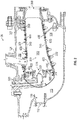
FIG. 2 and with continued reference toFIG. 1 , thecombustor section 26 of thegas turbine engine 20 is shown. As illustrated, acombustor 300 defines acombustion chamber 302. Thecombustion chamber 302 includes acombustion area 370 within thecombustion chamber 302. Thecombustor 300 includes aninlet 306 and anoutlet 308 through which air may pass. The air may be supplied to thecombustor 300 by a pre-diffuser 110. Air may also enter thecombustion chamber 302 through other holes in thecombustor 300 including but not limited to quenchholes 310, as seen inFIG. 2 . - Compressor air is supplied from the
compressor section 24 into apre-diffuser strut 112. As will be appreciated by those of skill in the art, thepre-diffuser strut 112 is configured to direct the airflow into the pre-diffuser 110, which then directs the airflow toward thecombustor 300. Thecombustor 300 and the pre-diffuser 110 are separated by ashroud chamber 113 that contains thecombustor 300 and includes aninner diameter branch 114 and anouter diameter branch 116. As air enters theshroud chamber 113, a portion of the air may flow into thecombustor inlet 306, a portion may flow into theinner diameter branch 114, and a portion may flow into theouter diameter branch 116. - The air from the
inner diameter branch 114 and theouter diameter branch 116 may then enter thecombustion chamber 302 by means of one or moreimpingement apertures 307 in thecombustion liner 600 and one or more effusion apertures (i.e. effusion holes) 309 in theheat shield panels 400. The impingement apertures 307 andeffusion apertures 309 may include nozzles, holes, etc. The air may then exit thecombustion chamber 302 through thecombustor outlet 308. At the same time, fuel may be supplied into thecombustion chamber 302 from afuel injector 320 and apilot nozzle 322, which may be ignited within thecombustion chamber 302. Thecombustor 300 of theengine combustion section 26 may be housed within ashroud case 124 which may define theshroud chamber 113. - The
combustor 300, as shown inFIG. 2 , includes multipleheat shield panels 400 that are attached to the combustion liner 600 (SeeFIG. 3 ). Theheat shield panels 400 may be arranged parallel to thecombustion liner 600. Thecombustion liner 600 can define circular or annular structures with theheat shield panels 400 being mounted on a radially inward liner and a radially outward liner, as will be appreciated by those of skill in the art. Theheat shield panels 400 can be removably mounted to thecombustion liner 600 by one ormore attachment mechanisms 332. In some embodiments, theattachment mechanism 332 may be integrally formed with a respectiveheat shield panel 400, although other configurations are possible. In some embodiments, theattachment mechanism 332 may be a bolt or other structure that may extend from the respectiveheat shield panel 400 through the interior surface to a receiving portion or aperture of thecombustion liner 600 such that theheat shield panel 400 may be attached to thecombustion liner 600 and held in place. Theheat shield panels 400 partially enclose acombustion area 370 within thecombustion chamber 302 of thecombustor 300. - Referring now to
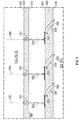
FIGs. 3 and4A-F with continued reference toFIGs. 1 and2 .FIG. 3 illustrates aheat shield panel 400 andcombustion liner 600 of a combustor 300 (seeFIG. 1 ) of a gas turbine engine 20 (seeFIG. 1 ). Theheat shield panel 400 and thecombustion liner 600 are in a facing spaced relationship. Theheat shield panel 400 includes afirst surface 410 oriented towards thecombustion area 370 of thecombustion chamber 302 and asecond surface 420 opposite thefirst surface 410 oriented towards thecombustion liner 600. Thecombustion liner 600 has aninner surface 610 and anouter surface 620 opposite theinner surface 610. Theinner surface 610 is oriented toward theheat shield panel 400. Theouter surface 620 is oriented outward from thecombustor 300 proximate theinner diameter branch 114 and theouter diameter branch 116. - The
combustion liner 600 includes a plurality ofimpingement apertures 307 configured to allowairflow 590 from theinner diameter branch 114 and theouter diameter branch 116 to enter animpingement cavity 390 in between thecombustion liner 600 and theheat shield panel 400. Each of theimpingement apertures 307 extend from theouter surface 620 to theinner surface 610 through thecombustion liner 600. - Each of the
impingement apertures 307 fluidly connects theimpingement cavity 390 to at least one of theinner diameter branch 114 and theouter diameter branch 116. Theheat shield panel 400 may include one ormore effusion apertures 309 configured to allowairflow 590 from theimpingement cavity 390 to thecombustion area 370 of thecombustion chamber 302. - Each of the
effusion apertures 309 extend from thesecond surface 420 to thefirst surface 410 through theheat shield panel 400.Airflow 590 flowing into theimpingement cavity 390 impinges on thesecond surface 420 of theheat shield panel 400 and absorbs heat from theheat shield panel 400 as it impinges on thesecond surface 420. As seen inFIG. 3 , particulate 592 may accompany theairflow 590 flowing into theimpingement cavity 390.Particulate 592 may include but is not limited to dirt, smoke, soot, volcanic ash, or similar airborne particulate known to one of skill in the art. As theairflow 590 and particulate 592 impinge upon thesecond surface 420 of theheat shield panel 400, the particulate 592 may begin to collect on thesecond surface 420, as seen inFIG. 3 .Particulate 592 collecting upon thesecond surface 420 of theheat shield panel 400 reduces the cooling efficiency ofairflow 590 impinging upon thesecond surface 420 and thus may increase local temperatures of theheat shield panel 400 and thecombustion liner 600.Particulate 592 collection upon thesecond surface 420 of theheat shield panel 400 may potentially create ablockage 593 to theeffusion apertures 309 in theheat shield panels 400, thus reducingairflow 590 into thecombustion area 370 of thecombustion chamber 302. Theblockage 593 may be a partial blockage or a full blockage. - The
heat shield panel 400 includes anaperture extension feature 500a-b configured to extend the length of theeffusion aperture 309. Theaperture extension feature 500a-b may extend outward from thesecond surface 420 of theheat shield panel 400 and into theimpingement cavity 390. Advantageously, the addition of anaperture extension feature 500a-b to theheat shield panel 400 increases the surface area of theheat shield panel 400 by extending theeffusion aperture 309, thus with more surface area the convention cooling ability of theeffusion aperture 309 increases. Theheat shield panel 400 may include one or more aperture extension features 500a-b. - The
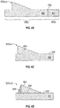
aperture extension feature 500a-b is configured to allowairflow 590 from theimpingement cavity 390 to enter through aninlet 502a-b proximate thesecond surface 420, convey theairflow 590 through apassageway 506a-b, to anoutlet 504a-b, leading into theeffusion aperture 309, and expel theairflow 590 from theeffusion aperture 309 into thecombustion area 370. Thepassageway 506a-b fluidly connects theimpingement cavity 390 to thecombustion area 370 through theeffusion aperture 309. Thepassageway 506a-b is fluidly connected toimpingement cavity 390 through theinlet 502a-b. Thepassageway 506a-b is fluidly connected toeffusion aperture 390 through theoutlet 504a-b. Theaperture extension feature 500a-b may be configured differently as shown inFIGs. 4A . Theaperture extension feature 500a-b may be integrally formed from theheat shield panel 400 or securely attached to theheat shield panel 400.FIG. 4B illustrates theaperture extension feature 500a-b being formed from afirst section 400a of aheat shield panel 400 and then secured to asecond section 400b of aheat shield panel 400 through a mechanical joint 402, such as, for example, a weld.FIG. 4C illustrates theaperture extension feature 500a-b being formed and then secured to thesecond surface 420 of theheat shield panel 400 through a mechanical joint 404, such as, for example, a weld or braze.FIG. 4D illustrates theaperture extension feature 500a-b being composed of twoseparate pieces second surface 420 of theheat shield panel 400 through a mechanical joint 404, such as, for example, a weld or braze. -
FIG. 4A illustrates a first configuration of anaperture extension feature 500a. A thickness T1 of theheat shield panel 400 is greater at the firstaperture extension feature 500a than a thickness T2 elsewhere in theheat shield panel 400, which allows theaperture extension feature 500a to extend away from thesecond surface 420 of theheat shield panel 400 into theimpingement cavity 390. - The
passageway 506a of theaperture extension feature 500a may include aguide wall 508a oriented at a selected angle α1, which may be equivalent to the angle β1 of theeffusion aperture 309. In the example illustrated inFIG. 4A , theguide wall 508a encloses thepassageway 506a. As illustrated inFIGs. 4A and4E , thepassageway 506a may be circular in shape but it is understood that thepassageway 506a may be shaped differently. The orientation of theinlet 502a may be about perpendicular to thesecond surface 420 of theheat shield panel 400, as shown inFIG. 4A . Also, as illustrated inFIG. 4E , theinlet 502a may be circular in shape but it is understood that theinlet 502a may be shaped differently. Theinlet 502a may be located at thesecond surface 420 of theheat shield panel 400, as seen inFIGs. 4A and4E . - The
inlet 502a may be located on afirst face 510a of theaperture extension feature 500a. Thefirst face 510a of theaperture extension feature 500a is oriented at a selected angle θ1 relative to thesecond surface 420 of theheat shield panel 400. In an embodiment, the selected angle θ1 greater than 0° but less than 120° (i.e. 0° < θ1 < 120°). In an embodiment, thefirst face 510a may be oriented about perpendicular to thesecond surface 420 of the heat shield panel 400 (i.e. θ1 ≈ 90°). Advantageously, by orienting thefirst face 510a at a selected angle about perpendicular or acute relative to thesecond surface 420 of theheat shield panel 400, it prevents thefirst face 510a from becoming a ramped surface that may facilitate particulate 592 to flow up thefirst face 510a and into theinlet 502a. In an alternate embodiment, the selected angle θ1 is an obtuse angle (i.e. 90° > θ1 > 180°). Advantageously, by orienting thefirst face 510a at a selected angle about obtuse relative to thesecond surface 420 of theheat shield panel 400, it allows theinlet 502a to be about normal to an axis B of thepassageway 309. - A
second face 512a is located opposite thefirst face 510a of theaperture extension feature 500a. Thesecond face 512a may be oriented at a selected angle θ2 relative to thesecond surface 420. In an embodiment, thesecond face 512a may be oriented at a selected angle θ2 about equal an angle θ3 of thepassageway 506a (i.e. θ2 = θ3). In another embodiment, thesecond face 512a may be oriented at a selected angle θ2 equal to or greater than the angle θ3 of thepassageway 506a (i.e. θ2 ≥ θ3). In another embodiment, thesecond face 512a may be oriented at a selected angle θ2 about equal to the selected angle α1 of theguide wall 508a of thepassageway 506a (i.e. θ2=α1). In another embodiment, thesecond face 512a may be oriented at a selected angle θ2 equal to or greater than the selected angle α1 of theguide wall 508a of thepassageway 506a (i.e. θ2 ≥ α1). -
FIG. 4A also illustrates a second configuration of anaperture extension feature 500b. A thickness T3 of theheat shield panel 400 is greater at the secondaperture extension feature 500b than a thickness T2 elsewhere in theheatshield panel 400, which allows theaperture extension feature 500b to extend away from thesecond surface 420 of theheat shield panel 400 into theimpingement cavity 390. - The
passageway 506b of theaperture extension feature 500b may include aguide wall 508b oriented at a selected angle α1, which may be equivalent to the angle β1 of theeffusion aperture 309. In the example illustrated inFIG. 4A , theguide wall 508b encloses thepassageway 506b. As illustrated inFIGs. 4A and4F , thepassageway 506b may be circular in shape but it is understood that thepassageway 506b may be shaped differently. The orientation of theinlet 502b may be about perpendicular to thesecond surface 420 of theheat shield panel 400, as shown inFIG. 4A . Also, as illustrated inFIG. 4F , theinlet 502b may be circular in shape but it is understood that theinlet 502b may be shaped differently. Theinlet 502b may be located at a selected distance D1 away from thesecond surface 420 of theheat shield panel 400, as seen inFIGs. 4A and4F . For example, theinlet 502b may be located outside of a boundary layer associated with thesecond surface 420 of theheat shield panel 400 within theimpingement cavity 390. Advantageously, particulate 592 ingestion into theinlet 502b and subsequently thecombustion area 370 is reduced by locating theinlet 502b a selected distance away from thesecond surface 420 of theheat shield panel 400 sinceparticulate 590 tends to collect at thesecond surface 420. - The
inlet 502b may be located on afirst face 510b of theaperture extension feature 500b. Thefirst face 510b of theaperture extension feature 500b is oriented at a selected angle θ1 relative to thesecond surface 420 of theheat shield panel 400. In an embodiment, the selected angle θ1 is greater than 0° but less than 120° (i.e. 0° < θ1 < 120°). In an embodiment, thefirst face 510b may be oriented about perpendicular to thesecond surface 420 of the heat shield panel 400 (i.e. θ1 ≈ 90°). Advantageously, by orienting thefirst face 510b at a selected angle about perpendicular or acute relative to thesecond surface 420 of theheat shield panel 400, it prevents thefirst face 510b from becoming a ramped surface that may facilitate particulate 592 to flow up thefirst face 510b and into theinlet 502b. In an alternate embodiment, the selected angle θ1 is an obtuse angle (i.e. 90° > θ1 > 180°). Advantageously, by orienting thefirst face 510b at a selected angle about obtuse relative to thesecond surface 420 of theheat shield panel 400, it allows theinlet 502b to be about normal to the an axis B of thepassageway 309. - A
second face 512b is located opposite thefirst face 510b of theaperture extension feature 500b. Thesecond face 512b may be oriented at a selected angle θ2 relative to thesecond surface 420. In an embodiment, thesecond face 512b may be oriented at a selected angle θ2 about equal an angle θ3 of thepassageway 506b (i.e. θ2 = θ3). In another embodiment, thesecond face 512b may be oriented at a selected angle θ2 equal to or greater than the angle θ3 of thepassageway 506b (i.e. θ2 ≥ θ3). In another embodiment, thesecond face 512b may be oriented at a selected angle θ2 about equal to the selected angle α1 of theguide wall 508b of thepassageway 506b (i.e. θ2=α1). In another embodiment, thesecond face 512b may be oriented at a selected angle θ2 equal to or greater than the selected angle α1 of theguide wall 508b of thepassageway 506b (i.e. θ2 ≥ α1). - It is understood that a combustor of a gas turbine engine is used for illustrative purposes and the embodiments disclosed herein may be applicable to additional components of other than a combustor of a gas turbine engine, such as, for example, a first component and a second component defining a cooling channel therebetween. The first component may have cooling holes similar to the impingement apertures and the second component may have cooling holes similar to the effusion holes. The cooling holes may direct air through the cooling channel to impinge upon the second component. The effusions holes direct air through the second component and in an area proximate the second component.
- Technical effects of embodiments of the present disclosure include incorporating an aperture extension feature into a heat shield panel of the combustor to increase surface area of the heat shield panel at effusion hole to increase the convention cooling ability of air flowing through the effusion holes, while helping to reduce entry of the particulate into the combustion area.
- The term "about" is intended to include the degree of error associated with measurement of the particular quantity based upon the equipment available at the time of filing the application. For example, "about" can include a non-limiting range of ± 8% or 5%, or 2% of a given value.
- The terminology used herein is for the purpose of describing particular embodiments only and is not intended to be limiting of the present disclosure. As used herein, the singular forms "a", "an" and "the" are intended to include the plural forms as well, unless the context clearly indicates otherwise. It will be further understood that the terms "comprises" and/or "comprising," when used in this specification, specify the presence of stated features, integers, steps, operations, elements, and/or components, but do not preclude the presence or addition of one or more other features, integers, steps, operations, element components, and/or groups thereof.
- While the present disclosure has been described with reference to an exemplary embodiment or embodiments, it will be understood by those skilled in the art that various changes may be made and equivalents may be substituted for elements thereof without departing from the scope of the present disclosure. In addition, many modifications may be made to adapt a particular situation or material to the teachings of the present disclosure without departing from the essential scope thereof. Therefore, it is intended that the present disclosure not be limited to the particular embodiment disclosed as the best mode contemplated for carrying out this present disclosure, but that the present disclosure will include all embodiments falling within the scope of the claims.
Claims (14)
- A gas turbine engine component assembly, comprising:a first component (600) having a first surface (610) and a second surface (620) opposite the first surface, wherein the first component includes a cooling hole (307) extending from the second surface to the first surface through the first component;a second component (400) having a first surface (410) and a second surface (420), the first surface of the first component and the second surface of the second component defining a cooling channel (390) therebetween in fluid communication with the cooling hole for cooling the second surface of the second component; andan aperture extension feature (500a-b) in the second component and extending outward from the second surface of the second component into the cooling channel, the aperture extension feature including a passageway (506a-b) fluidly connecting the cooling channel to an area (370) located proximate to the first surface of the second component,wherein the aperture extension feature includes a first face (510a-b) and an inlet (502a-b) located in the first face to fluidly connect the passageway to the cooling channel, the first face being oriented at a selected angle (θ1) between 0° and 120° relative to the second surface of the second component.
- The gas turbine engine component assembly of claim 1, wherein the first face (510a-b) extends outward from the second surface (420) of the second component (400) into the cooling channel (390).
- The gas turbine engine component assembly of claim 1 or claim 2, wherein the selected angle (θ1) is equal to 90°.
- The gas turbine engine component assembly of claim 1 or claim 2, wherein the selected angle (θ1) is an acute angle.
- The gas turbine engine component assembly of any preceding claim, wherein the inlet (502a-b) is located at the second surface (420) of the second component (400).
- The gas turbine engine component assembly of any of claims 1 to 4, wherein the inlet (502a-b) is located a selected distance (D1) away from the second surface (420) of the second component (400).
- The gas turbine engine component assembly of claim 6, wherein the selected distance (D1) is outside of a boundary layer associated with the second surface (420) of the second component (400) within the cooling channel (390).
- The gas turbine engine component assembly of any preceding claim, wherein the second component (400) further comprises a cooling hole (309) extending from the second surface (420) of the second component to the first surface (410) of the second component and fluidly connecting the passageway (506a-b) to the area (370) located proximate the first surface of the second component, and
wherein the passageway includes an outlet (504a-b) that fluidly connects the passageway to the cooling hole of the second component. - The gas turbine engine component assembly of any preceding claim, wherein the aperture extension feature (500a-b) is integrally formed in the second component (400).
- The gas turbine engine component assembly of any of claims 1 to 8, wherein the aperture extension feature (500a-b) is attached to the second surface (420) of the second component (400) through a mechanical joint (404).
- A combustor (300) for use in a gas turbine engine, the combustor enclosing a combustion chamber (302) having a combustion area (370), wherein the combustor comprises a gas turbine component assembly as claimed for in any of clams 1 to 7; wherein
the first component is a combustion liner (600) of the combustor,
the first surface of the first component is an inner surface (610) of the combustion liner,
the second surface of the first component is an outer surface (620) of the combustion liner,
the cooling hole of the first component is an impingement aperture (307),
the second component is a heat shield panel (400) of the combustor,
the cooling channel is an impingement cavity (390) of the combustor, and
the area located proximate to the first surface of the second component is the combustion area. - The combustor of claim 11, wherein the heat shield panel (400) further comprises an effusion aperture (309) extending from the second surface (420) of the heat shield panel to the first surface (410) of the heat shield panel and fluidly connecting the passageway (506a-b) to the combustion area (370), and
wherein the passageway includes an outlet (504a-b) that fluidly connects the passageway to the effusion aperture of the heat shield panel. - The combustor of claim 11 or claim 12, wherein the aperture extension feature (500a-b) is integrally formed in the heat shield panel (400).
- The combustor of claim 11 or claim 12, wherein the aperture extension feature (500a-b) is attached to the second surface (420) of the heat shield panel (400) through a mechanical joint (404).
Applications Claiming Priority (1)
| Application Number | Priority Date | Filing Date | Title |
|---|---|---|---|
| US15/925,223 US10823414B2 (en) | 2018-03-19 | 2018-03-19 | Hooded entrance to effusion holes |
Publications (2)
| Publication Number | Publication Date |
|---|---|
| EP3543477A1 true EP3543477A1 (en) | 2019-09-25 |
| EP3543477B1 EP3543477B1 (en) | 2023-09-13 |
Family
ID=65904025
Family Applications (1)
| Application Number | Title | Priority Date | Filing Date |
|---|---|---|---|
| EP19163888.1A Active EP3543477B1 (en) | 2018-03-19 | 2019-03-19 | Hooded entrance to effusion holes |
Country Status (2)
| Country | Link |
|---|---|
| US (1) | US10823414B2 (en) |
| EP (1) | EP3543477B1 (en) |
Citations (7)
| Publication number | Priority date | Publication date | Assignee | Title |
|---|---|---|---|---|
| WO1995025932A1 (en) * | 1989-08-31 | 1995-09-28 | Alliedsignal Inc. | Turbine combustor cooling system |
| EP1205635A2 (en) * | 2000-11-03 | 2002-05-15 | General Electric Company | Gas injector system and its fabrication |
| EP2584148A1 (en) * | 2011-10-21 | 2013-04-24 | Siemens Aktiengesellschaft | Film-cooled turbine blade for a turbomachine |
| JP2014148938A (en) * | 2013-02-01 | 2014-08-21 | Siemens Ag | Film-cooled turbine blade for turbomachine |
| EP3032175A1 (en) * | 2014-12-12 | 2016-06-15 | United Technologies Corporation | A cooled wall assembly for a combustor and method of design |
| WO2016099662A2 (en) * | 2014-10-31 | 2016-06-23 | General Electric Company | Engine component assembly |
| EP3239462A1 (en) * | 2016-04-26 | 2017-11-01 | General Electric Company | Airfoil for a turbine engine |
Family Cites Families (8)
| Publication number | Priority date | Publication date | Assignee | Title |
|---|---|---|---|---|
| US3777484A (en) * | 1971-12-08 | 1973-12-11 | Gen Electric | Shrouded combustion liner |
| DE102007018061A1 (en) * | 2007-04-17 | 2008-10-23 | Rolls-Royce Deutschland Ltd & Co Kg | Gas turbine combustion chamber wall |
| DE102013003444A1 (en) | 2013-02-26 | 2014-09-11 | Rolls-Royce Deutschland Ltd & Co Kg | Impact-cooled shingle of a gas turbine combustor with extended effusion holes |
| US20160123592A1 (en) * | 2013-06-14 | 2016-05-05 | United Technologies Corporation | Gas turbine engine combustor liner panel |
| JP6246562B2 (en) * | 2013-11-05 | 2017-12-13 | 三菱日立パワーシステムズ株式会社 | Gas turbine combustor |
| DE102013223258A1 (en) * | 2013-11-14 | 2015-06-03 | Rolls-Royce Deutschland Ltd & Co Kg | Combustion heat shield element of a gas turbine |
| DE102015225505A1 (en) | 2015-12-16 | 2017-06-22 | Rolls-Royce Deutschland Ltd & Co Kg | Wall of a component to be cooled by means of cooling air, in particular a gas turbine combustion chamber wall |
| US10495309B2 (en) | 2016-02-12 | 2019-12-03 | General Electric Company | Surface contouring of a flowpath wall of a gas turbine engine |
-
2018
- 2018-03-19 US US15/925,223 patent/US10823414B2/en active Active
-
2019
- 2019-03-19 EP EP19163888.1A patent/EP3543477B1/en active Active
Patent Citations (7)
| Publication number | Priority date | Publication date | Assignee | Title |
|---|---|---|---|---|
| WO1995025932A1 (en) * | 1989-08-31 | 1995-09-28 | Alliedsignal Inc. | Turbine combustor cooling system |
| EP1205635A2 (en) * | 2000-11-03 | 2002-05-15 | General Electric Company | Gas injector system and its fabrication |
| EP2584148A1 (en) * | 2011-10-21 | 2013-04-24 | Siemens Aktiengesellschaft | Film-cooled turbine blade for a turbomachine |
| JP2014148938A (en) * | 2013-02-01 | 2014-08-21 | Siemens Ag | Film-cooled turbine blade for turbomachine |
| WO2016099662A2 (en) * | 2014-10-31 | 2016-06-23 | General Electric Company | Engine component assembly |
| EP3032175A1 (en) * | 2014-12-12 | 2016-06-15 | United Technologies Corporation | A cooled wall assembly for a combustor and method of design |
| EP3239462A1 (en) * | 2016-04-26 | 2017-11-01 | General Electric Company | Airfoil for a turbine engine |
Also Published As
| Publication number | Publication date |
|---|---|
| EP3543477B1 (en) | 2023-09-13 |
| US20190285277A1 (en) | 2019-09-19 |
| US10823414B2 (en) | 2020-11-03 |
Similar Documents
| Publication | Publication Date | Title |
|---|---|---|
| EP3502440B1 (en) | Gas turbine engine component assembly | |
| EP3502562B1 (en) | Apparatus and method for mitigating particulate accumulation on a component of a gas turbine engine | |
| US20220381434A1 (en) | Apparatus and method for mitigating particulate accumulation on a component of a gas turbine | |
| US20240247613A1 (en) | Apparatus and method for mitigating airflow separation around engine combustor | |
| EP3734161A1 (en) | Combustor liner panel with micro-circuit core cooling | |
| US11092339B2 (en) | Apparatus and method for mitigating particulate accumulation on a component of a gas turbine | |
| US20220316705A1 (en) | Apparatus and method for mitigating particulate accumulation on a component of a gas turbine | |
| US11371703B2 (en) | Apparatus and method for mitigating particulate accumulation on a component of a gas turbine | |
| EP3492813B1 (en) | Apparatus for mitigating particulate accumulation on a shell of a combustor of a gas turbine engine | |
| EP3502564B1 (en) | Combustor shell mitigating particulate accumulation on the bulkhead of a gas turbine engine | |
| US11098653B2 (en) | Apparatus and method for mitigating particulate accumulation on a component of a gas turbine | |
| EP3511624B1 (en) | Combustor for a gas turbine engine mitigating particulate accumulation | |
| US11262071B2 (en) | Combustor particulate deflector | |
| EP3543477B1 (en) | Hooded entrance to effusion holes |
Legal Events
| Date | Code | Title | Description |
|---|---|---|---|
| PUAI | Public reference made under article 153(3) epc to a published international application that has entered the european phase |
Free format text: ORIGINAL CODE: 0009012 |
|
| STAA | Information on the status of an ep patent application or granted ep patent |
Free format text: STATUS: THE APPLICATION HAS BEEN PUBLISHED |
|
| AK | Designated contracting states |
Kind code of ref document: A1 Designated state(s): AL AT BE BG CH CY CZ DE DK EE ES FI FR GB GR HR HU IE IS IT LI LT LU LV MC MK MT NL NO PL PT RO RS SE SI SK SM TR |
|
| AX | Request for extension of the european patent |
Extension state: BA ME |
|
| STAA | Information on the status of an ep patent application or granted ep patent |
Free format text: STATUS: REQUEST FOR EXAMINATION WAS MADE |
|
| 17P | Request for examination filed |
Effective date: 20200325 |
|
| RBV | Designated contracting states (corrected) |
Designated state(s): AL AT BE BG CH CY CZ DE DK EE ES FI FR GB GR HR HU IE IS IT LI LT LU LV MC MK MT NL NO PL PT RO RS SE SI SK SM TR |
|
| RAP1 | Party data changed (applicant data changed or rights of an application transferred) |
Owner name: RAYTHEON TECHNOLOGIES CORPORATION |
|
| GRAP | Despatch of communication of intention to grant a patent |
Free format text: ORIGINAL CODE: EPIDOSNIGR1 |
|
| STAA | Information on the status of an ep patent application or granted ep patent |
Free format text: STATUS: GRANT OF PATENT IS INTENDED |
|
| INTG | Intention to grant announced |
Effective date: 20220926 |
|
| GRAJ | Information related to disapproval of communication of intention to grant by the applicant or resumption of examination proceedings by the epo deleted |
Free format text: ORIGINAL CODE: EPIDOSDIGR1 |
|
| STAA | Information on the status of an ep patent application or granted ep patent |
Free format text: STATUS: REQUEST FOR EXAMINATION WAS MADE |
|
| INTC | Intention to grant announced (deleted) | ||
| GRAP | Despatch of communication of intention to grant a patent |
Free format text: ORIGINAL CODE: EPIDOSNIGR1 |
|
| STAA | Information on the status of an ep patent application or granted ep patent |
Free format text: STATUS: GRANT OF PATENT IS INTENDED |
|
| INTG | Intention to grant announced |
Effective date: 20230421 |
|
| GRAS | Grant fee paid |
Free format text: ORIGINAL CODE: EPIDOSNIGR3 |
|
| GRAA | (expected) grant |
Free format text: ORIGINAL CODE: 0009210 |
|
| STAA | Information on the status of an ep patent application or granted ep patent |
Free format text: STATUS: THE PATENT HAS BEEN GRANTED |
|
| AK | Designated contracting states |
Kind code of ref document: B1 Designated state(s): AL AT BE BG CH CY CZ DE DK EE ES FI FR GB GR HR HU IE IS IT LI LT LU LV MC MK MT NL NO PL PT RO RS SE SI SK SM TR |
|
| REG | Reference to a national code |
Ref country code: CH Ref legal event code: EP |
|
| REG | Reference to a national code |
Ref country code: DE Ref legal event code: R096 Ref document number: 602019037203 Country of ref document: DE |
|
| REG | Reference to a national code |
Ref country code: IE Ref legal event code: FG4D |
|
| RAP4 | Party data changed (patent owner data changed or rights of a patent transferred) |
Owner name: RTX CORPORATION |
|
| REG | Reference to a national code |
Ref country code: LT Ref legal event code: MG9D |
|
| REG | Reference to a national code |
Ref country code: NL Ref legal event code: MP Effective date: 20230913 |
|
| PG25 | Lapsed in a contracting state [announced via postgrant information from national office to epo] |
Ref country code: GR Free format text: LAPSE BECAUSE OF FAILURE TO SUBMIT A TRANSLATION OF THE DESCRIPTION OR TO PAY THE FEE WITHIN THE PRESCRIBED TIME-LIMIT Effective date: 20231214 |
|
| PG25 | Lapsed in a contracting state [announced via postgrant information from national office to epo] |
Ref country code: SE Free format text: LAPSE BECAUSE OF FAILURE TO SUBMIT A TRANSLATION OF THE DESCRIPTION OR TO PAY THE FEE WITHIN THE PRESCRIBED TIME-LIMIT Effective date: 20230913 Ref country code: RS Free format text: LAPSE BECAUSE OF FAILURE TO SUBMIT A TRANSLATION OF THE DESCRIPTION OR TO PAY THE FEE WITHIN THE PRESCRIBED TIME-LIMIT Effective date: 20230913 Ref country code: NO Free format text: LAPSE BECAUSE OF FAILURE TO SUBMIT A TRANSLATION OF THE DESCRIPTION OR TO PAY THE FEE WITHIN THE PRESCRIBED TIME-LIMIT Effective date: 20231213 Ref country code: LV Free format text: LAPSE BECAUSE OF FAILURE TO SUBMIT A TRANSLATION OF THE DESCRIPTION OR TO PAY THE FEE WITHIN THE PRESCRIBED TIME-LIMIT Effective date: 20230913 Ref country code: LT Free format text: LAPSE BECAUSE OF FAILURE TO SUBMIT A TRANSLATION OF THE DESCRIPTION OR TO PAY THE FEE WITHIN THE PRESCRIBED TIME-LIMIT Effective date: 20230913 Ref country code: HR Free format text: LAPSE BECAUSE OF FAILURE TO SUBMIT A TRANSLATION OF THE DESCRIPTION OR TO PAY THE FEE WITHIN THE PRESCRIBED TIME-LIMIT Effective date: 20230913 Ref country code: GR Free format text: LAPSE BECAUSE OF FAILURE TO SUBMIT A TRANSLATION OF THE DESCRIPTION OR TO PAY THE FEE WITHIN THE PRESCRIBED TIME-LIMIT Effective date: 20231214 Ref country code: FI Free format text: LAPSE BECAUSE OF FAILURE TO SUBMIT A TRANSLATION OF THE DESCRIPTION OR TO PAY THE FEE WITHIN THE PRESCRIBED TIME-LIMIT Effective date: 20230913 |
|
| REG | Reference to a national code |
Ref country code: AT Ref legal event code: MK05 Ref document number: 1611506 Country of ref document: AT Kind code of ref document: T Effective date: 20230913 |
|
| PG25 | Lapsed in a contracting state [announced via postgrant information from national office to epo] |
Ref country code: NL Free format text: LAPSE BECAUSE OF FAILURE TO SUBMIT A TRANSLATION OF THE DESCRIPTION OR TO PAY THE FEE WITHIN THE PRESCRIBED TIME-LIMIT Effective date: 20230913 |
|
| PG25 | Lapsed in a contracting state [announced via postgrant information from national office to epo] |
Ref country code: IS Free format text: LAPSE BECAUSE OF FAILURE TO SUBMIT A TRANSLATION OF THE DESCRIPTION OR TO PAY THE FEE WITHIN THE PRESCRIBED TIME-LIMIT Effective date: 20240113 |
|
| PG25 | Lapsed in a contracting state [announced via postgrant information from national office to epo] |
Ref country code: AT Free format text: LAPSE BECAUSE OF FAILURE TO SUBMIT A TRANSLATION OF THE DESCRIPTION OR TO PAY THE FEE WITHIN THE PRESCRIBED TIME-LIMIT Effective date: 20230913 |
|
| PG25 | Lapsed in a contracting state [announced via postgrant information from national office to epo] |
Ref country code: ES Free format text: LAPSE BECAUSE OF FAILURE TO SUBMIT A TRANSLATION OF THE DESCRIPTION OR TO PAY THE FEE WITHIN THE PRESCRIBED TIME-LIMIT Effective date: 20230913 |
|
| PG25 | Lapsed in a contracting state [announced via postgrant information from national office to epo] |
Ref country code: SM Free format text: LAPSE BECAUSE OF FAILURE TO SUBMIT A TRANSLATION OF THE DESCRIPTION OR TO PAY THE FEE WITHIN THE PRESCRIBED TIME-LIMIT Effective date: 20230913 Ref country code: RO Free format text: LAPSE BECAUSE OF FAILURE TO SUBMIT A TRANSLATION OF THE DESCRIPTION OR TO PAY THE FEE WITHIN THE PRESCRIBED TIME-LIMIT Effective date: 20230913 Ref country code: IS Free format text: LAPSE BECAUSE OF FAILURE TO SUBMIT A TRANSLATION OF THE DESCRIPTION OR TO PAY THE FEE WITHIN THE PRESCRIBED TIME-LIMIT Effective date: 20240113 Ref country code: ES Free format text: LAPSE BECAUSE OF FAILURE TO SUBMIT A TRANSLATION OF THE DESCRIPTION OR TO PAY THE FEE WITHIN THE PRESCRIBED TIME-LIMIT Effective date: 20230913 Ref country code: EE Free format text: LAPSE BECAUSE OF FAILURE TO SUBMIT A TRANSLATION OF THE DESCRIPTION OR TO PAY THE FEE WITHIN THE PRESCRIBED TIME-LIMIT Effective date: 20230913 Ref country code: CZ Free format text: LAPSE BECAUSE OF FAILURE TO SUBMIT A TRANSLATION OF THE DESCRIPTION OR TO PAY THE FEE WITHIN THE PRESCRIBED TIME-LIMIT Effective date: 20230913 Ref country code: AT Free format text: LAPSE BECAUSE OF FAILURE TO SUBMIT A TRANSLATION OF THE DESCRIPTION OR TO PAY THE FEE WITHIN THE PRESCRIBED TIME-LIMIT Effective date: 20230913 Ref country code: SK Free format text: LAPSE BECAUSE OF FAILURE TO SUBMIT A TRANSLATION OF THE DESCRIPTION OR TO PAY THE FEE WITHIN THE PRESCRIBED TIME-LIMIT Effective date: 20230913 Ref country code: PT Free format text: LAPSE BECAUSE OF FAILURE TO SUBMIT A TRANSLATION OF THE DESCRIPTION OR TO PAY THE FEE WITHIN THE PRESCRIBED TIME-LIMIT Effective date: 20240115 |
|
| PG25 | Lapsed in a contracting state [announced via postgrant information from national office to epo] |
Ref country code: PL Free format text: LAPSE BECAUSE OF FAILURE TO SUBMIT A TRANSLATION OF THE DESCRIPTION OR TO PAY THE FEE WITHIN THE PRESCRIBED TIME-LIMIT Effective date: 20230913 Ref country code: IT Free format text: LAPSE BECAUSE OF FAILURE TO SUBMIT A TRANSLATION OF THE DESCRIPTION OR TO PAY THE FEE WITHIN THE PRESCRIBED TIME-LIMIT Effective date: 20230913 |
|
| REG | Reference to a national code |
Ref country code: DE Ref legal event code: R097 Ref document number: 602019037203 Country of ref document: DE |
|
| PG25 | Lapsed in a contracting state [announced via postgrant information from national office to epo] |
Ref country code: DK Free format text: LAPSE BECAUSE OF FAILURE TO SUBMIT A TRANSLATION OF THE DESCRIPTION OR TO PAY THE FEE WITHIN THE PRESCRIBED TIME-LIMIT Effective date: 20230913 |
|
| PLBE | No opposition filed within time limit |
Free format text: ORIGINAL CODE: 0009261 |
|
| STAA | Information on the status of an ep patent application or granted ep patent |
Free format text: STATUS: NO OPPOSITION FILED WITHIN TIME LIMIT |
|
| PG25 | Lapsed in a contracting state [announced via postgrant information from national office to epo] |
Ref country code: DK Free format text: LAPSE BECAUSE OF FAILURE TO SUBMIT A TRANSLATION OF THE DESCRIPTION OR TO PAY THE FEE WITHIN THE PRESCRIBED TIME-LIMIT Effective date: 20230913 |
|
| 26N | No opposition filed |
Effective date: 20240614 |
|
| PG25 | Lapsed in a contracting state [announced via postgrant information from national office to epo] |
Ref country code: SI Free format text: LAPSE BECAUSE OF FAILURE TO SUBMIT A TRANSLATION OF THE DESCRIPTION OR TO PAY THE FEE WITHIN THE PRESCRIBED TIME-LIMIT Effective date: 20230913 |
|
| PG25 | Lapsed in a contracting state [announced via postgrant information from national office to epo] |
Ref country code: SI Free format text: LAPSE BECAUSE OF FAILURE TO SUBMIT A TRANSLATION OF THE DESCRIPTION OR TO PAY THE FEE WITHIN THE PRESCRIBED TIME-LIMIT Effective date: 20230913 |
|
| REG | Reference to a national code |
Ref country code: CH Ref legal event code: PL |
|
| PG25 | Lapsed in a contracting state [announced via postgrant information from national office to epo] |
Ref country code: BG Free format text: LAPSE BECAUSE OF FAILURE TO SUBMIT A TRANSLATION OF THE DESCRIPTION OR TO PAY THE FEE WITHIN THE PRESCRIBED TIME-LIMIT Effective date: 20230913 |
|
| PG25 | Lapsed in a contracting state [announced via postgrant information from national office to epo] |
Ref country code: LU Free format text: LAPSE BECAUSE OF NON-PAYMENT OF DUE FEES Effective date: 20240319 |
|
| PG25 | Lapsed in a contracting state [announced via postgrant information from national office to epo] |
Ref country code: MC Free format text: LAPSE BECAUSE OF FAILURE TO SUBMIT A TRANSLATION OF THE DESCRIPTION OR TO PAY THE FEE WITHIN THE PRESCRIBED TIME-LIMIT Effective date: 20230913 |
|
| PG25 | Lapsed in a contracting state [announced via postgrant information from national office to epo] |
Ref country code: MC Free format text: LAPSE BECAUSE OF FAILURE TO SUBMIT A TRANSLATION OF THE DESCRIPTION OR TO PAY THE FEE WITHIN THE PRESCRIBED TIME-LIMIT Effective date: 20230913 Ref country code: LU Free format text: LAPSE BECAUSE OF NON-PAYMENT OF DUE FEES Effective date: 20240319 Ref country code: BG Free format text: LAPSE BECAUSE OF FAILURE TO SUBMIT A TRANSLATION OF THE DESCRIPTION OR TO PAY THE FEE WITHIN THE PRESCRIBED TIME-LIMIT Effective date: 20230913 |
|
| REG | Reference to a national code |
Ref country code: BE Ref legal event code: MM Effective date: 20240331 |
|
| PG25 | Lapsed in a contracting state [announced via postgrant information from national office to epo] |
Ref country code: BE Free format text: LAPSE BECAUSE OF NON-PAYMENT OF DUE FEES Effective date: 20240331 |
|
| PG25 | Lapsed in a contracting state [announced via postgrant information from national office to epo] |
Ref country code: IE Free format text: LAPSE BECAUSE OF NON-PAYMENT OF DUE FEES Effective date: 20240319 |
|
| PG25 | Lapsed in a contracting state [announced via postgrant information from national office to epo] |
Ref country code: IE Free format text: LAPSE BECAUSE OF NON-PAYMENT OF DUE FEES Effective date: 20240319 Ref country code: BE Free format text: LAPSE BECAUSE OF NON-PAYMENT OF DUE FEES Effective date: 20240331 Ref country code: CH Free format text: LAPSE BECAUSE OF NON-PAYMENT OF DUE FEES Effective date: 20240331 |
|
| PG25 | Lapsed in a contracting state [announced via postgrant information from national office to epo] |
Ref country code: CY Free format text: LAPSE BECAUSE OF FAILURE TO SUBMIT A TRANSLATION OF THE DESCRIPTION OR TO PAY THE FEE WITHIN THE PRESCRIBED TIME-LIMIT; INVALID AB INITIO Effective date: 20190319 |
|
| PG25 | Lapsed in a contracting state [announced via postgrant information from national office to epo] |
Ref country code: HU Free format text: LAPSE BECAUSE OF FAILURE TO SUBMIT A TRANSLATION OF THE DESCRIPTION OR TO PAY THE FEE WITHIN THE PRESCRIBED TIME-LIMIT; INVALID AB INITIO Effective date: 20190319 |
|
| REG | Reference to a national code |
Ref country code: DE Ref legal event code: R081 Ref document number: 602019037203 Country of ref document: DE Owner name: RTX CORPORATION (N.D.GES.D. STAATES DELAWARE),, US Free format text: FORMER OWNER: RAYTHEON TECHNOLOGIES CORPORATION, FARMINGTON, CT, US |
|
| PG25 | Lapsed in a contracting state [announced via postgrant information from national office to epo] |
Ref country code: TR Free format text: LAPSE BECAUSE OF FAILURE TO SUBMIT A TRANSLATION OF THE DESCRIPTION OR TO PAY THE FEE WITHIN THE PRESCRIBED TIME-LIMIT Effective date: 20230913 |
|
| P01 | Opt-out of the competence of the unified patent court (upc) registered |
Free format text: CASE NUMBER: UPC_APP_0019172_3543477/2025 Effective date: 20251223 |
|
| PGFP | Annual fee paid to national office [announced via postgrant information from national office to epo] |
Ref country code: GB Payment date: 20260219 Year of fee payment: 8 |
|
| PGFP | Annual fee paid to national office [announced via postgrant information from national office to epo] |
Ref country code: DE Payment date: 20260219 Year of fee payment: 8 |
|
| PGFP | Annual fee paid to national office [announced via postgrant information from national office to epo] |
Ref country code: FR Payment date: 20260220 Year of fee payment: 8 |