EP3543441A1 - Optical shield for keypad locks - Google Patents
Optical shield for keypad locks Download PDFInfo
- Publication number
- EP3543441A1 EP3543441A1 EP19382197.2A EP19382197A EP3543441A1 EP 3543441 A1 EP3543441 A1 EP 3543441A1 EP 19382197 A EP19382197 A EP 19382197A EP 3543441 A1 EP3543441 A1 EP 3543441A1
- Authority
- EP
- European Patent Office
- Prior art keywords
- frame
- keypad
- lock
- structures
- shield
- Prior art date
- Legal status (The legal status is an assumption and is not a legal conclusion. Google has not performed a legal analysis and makes no representation as to the accuracy of the status listed.)
- Granted
Links
- 230000003287 optical effect Effects 0.000 title claims abstract description 8
- 230000002452 interceptive effect Effects 0.000 claims abstract description 4
- 230000008859 change Effects 0.000 description 3
- 230000004075 alteration Effects 0.000 description 2
- 230000000694 effects Effects 0.000 description 2
- 230000001419 dependent effect Effects 0.000 description 1
- 230000004048 modification Effects 0.000 description 1
- 238000012986 modification Methods 0.000 description 1
- 230000009182 swimming Effects 0.000 description 1
Images



Classifications
-
- E—FIXED CONSTRUCTIONS
- E05—LOCKS; KEYS; WINDOW OR DOOR FITTINGS; SAFES
- E05B—LOCKS; ACCESSORIES THEREFOR; HANDCUFFS
- E05B37/00—Permutation or combination locks; Puzzle locks
- E05B37/0003—Permutation or combination locks; Puzzle locks preventing detection of the combination
- E05B37/0006—Permutation or combination locks; Puzzle locks preventing detection of the combination by avoiding unauthorized viewing of the combination
-
- E—FIXED CONSTRUCTIONS
- E05—LOCKS; KEYS; WINDOW OR DOOR FITTINGS; SAFES
- E05B—LOCKS; ACCESSORIES THEREFOR; HANDCUFFS
- E05B9/00—Lock casings or latch-mechanism casings ; Fastening locks or fasteners or parts thereof to the wing
- E05B9/002—Faceplates or front plates
-
- E—FIXED CONSTRUCTIONS
- E05—LOCKS; KEYS; WINDOW OR DOOR FITTINGS; SAFES
- E05B—LOCKS; ACCESSORIES THEREFOR; HANDCUFFS
- E05B17/00—Accessories in connection with locks
- E05B17/22—Means for operating or controlling lock or fastening device accessories, i.e. other than the fastening members, e.g. switches, indicators
-
- E—FIXED CONSTRUCTIONS
- E05—LOCKS; KEYS; WINDOW OR DOOR FITTINGS; SAFES
- E05B—LOCKS; ACCESSORIES THEREFOR; HANDCUFFS
- E05B47/00—Operating or controlling locks or other fastening devices by electric or magnetic means
-
- G—PHYSICS
- G07—CHECKING-DEVICES
- G07C—TIME OR ATTENDANCE REGISTERS; REGISTERING OR INDICATING THE WORKING OF MACHINES; GENERATING RANDOM NUMBERS; VOTING OR LOTTERY APPARATUS; ARRANGEMENTS, SYSTEMS OR APPARATUS FOR CHECKING NOT PROVIDED FOR ELSEWHERE
- G07C9/00—Individual registration on entry or exit
- G07C9/00174—Electronically operated locks; Circuits therefor; Nonmechanical keys therefor, e.g. passive or active electrical keys or other data carriers without mechanical keys
- G07C9/00944—Details of construction or manufacture
-
- G—PHYSICS
- G07—CHECKING-DEVICES
- G07F—COIN-FREED OR LIKE APPARATUS
- G07F19/00—Complete banking systems; Coded card-freed arrangements adapted for dispensing or receiving monies or the like and posting such transactions to existing accounts, e.g. automatic teller machines
- G07F19/20—Automatic teller machines [ATMs]
- G07F19/205—Housing aspects of ATMs
-
- G—PHYSICS
- G07—CHECKING-DEVICES
- G07F—COIN-FREED OR LIKE APPARATUS
- G07F7/00—Mechanisms actuated by objects other than coins to free or to actuate vending, hiring, coin or paper currency dispensing or refunding apparatus
- G07F7/08—Mechanisms actuated by objects other than coins to free or to actuate vending, hiring, coin or paper currency dispensing or refunding apparatus by coded identity card or credit card or other personal identification means
- G07F7/10—Mechanisms actuated by objects other than coins to free or to actuate vending, hiring, coin or paper currency dispensing or refunding apparatus by coded identity card or credit card or other personal identification means together with a coded signal, e.g. in the form of personal identification information, like personal identification number [PIN] or biometric data
- G07F7/1025—Identification of user by a PIN code
- G07F7/1033—Details of the PIN pad
-
- E—FIXED CONSTRUCTIONS
- E05—LOCKS; KEYS; WINDOW OR DOOR FITTINGS; SAFES
- E05B—LOCKS; ACCESSORIES THEREFOR; HANDCUFFS
- E05B9/00—Lock casings or latch-mechanism casings ; Fastening locks or fasteners or parts thereof to the wing
- E05B2009/004—Shape of the lock housing
-
- G—PHYSICS
- G07—CHECKING-DEVICES
- G07F—COIN-FREED OR LIKE APPARATUS
- G07F19/00—Complete banking systems; Coded card-freed arrangements adapted for dispensing or receiving monies or the like and posting such transactions to existing accounts, e.g. automatic teller machines
- G07F19/20—Automatic teller machines [ATMs]
- G07F19/205—Housing aspects of ATMs
- G07F19/2055—Anti-skimming aspects at ATMs
Definitions
- the purpose of the invention is an optical shield for keypad locks, used to prevent, impede or obstruct third parties from seeing the lock's code while the user is operating it.
- the purpose of the invention is an optical shield that, mounted on the lock itself (when it is, in turn, mounted and functioning in its operative site), consists of a solution to prevent, impede or obstruct optical access to the lock's keypad while the user is using it. It is characterised in that it consists of, at least, a frame provided in one or several structures in which the standard keypad structures fit; one or several side panels that project from the body of the frame impeding the lateral and/or vertical view of the lock from an area next to the user; and the means to indirectly fasten the frame to the module/keypad of the lock, without interfering with it.
- the purpose of the invention is an optical shield for keypad locks, which consists of, at least, a frame (1) with one or several side panels (12) that project from the frame body (1) impeding the lateral view of the keypad for the lock (C) from a location near the user who is operating it.
- the cited frame (1) is provided with one or several structures (11) in which other standard structures (C1) fit, which keypads for locks (C) have as a series.
- the specific configuration/geometry of these structures (11), (C1) is indifferent for the effect of the invention and they can vary according to the different models/manufacturers existing in the market. It is basic for the effects of the invention that these structures fit different models without requiring any alteration in them, or in the lock or in its keypad (which are already installed and functioning).
- the cited structures (11) have vertical grooves made in the back of the frame (1), situated in pairs and provided with some openings (11a) in one of its ends.
- the cited standard structures (C1) are first placed at the opening (11a) and then they are slid down along the form (11) until finally the frame (1) is positioned in the area of the keypad so that the side panels (12) that project from the body of the frame (1) impede the lateral view of the keypad from an area next to the user who is operating it.
- the cited frame (1) also has means (2) to fasten it indirectly to the lock module/keypad (C), without interfering with it.
- the cited means (2) are, at least, a plate (21) fastened to the frame (1) closing the structures (11) to impede the accidental or malicious removal of the frame (1).
- the mounting and fastening of the plate (21) in the frame (1) takes place, for example (see figure 2c ), using a hole (22) lined up with another treaded blind hole made in the body of the frame (1); and having a tab (23) lined up with a recess made in the body of the frame (1).
- the fastening that impedes the undesired (accidental or malicious) removal of the shield that is the subject of the invention takes place inserting the tab (23) in the recess and inserting a safety screw (4) in the confronted holes.
- the shield that is the subject of the invention additionally, may have an additional panel (3) mounted on the frame (1) and is capable of sliding linearly in it.
- This additional panel (3) is provided with, at least, a window (31) through which one may access a restricted area of the keypad, impeding the frontal view of the rest.
- this additional panel (3) is placed in its guide rails (13) made in the body of the frame (1) and specifically in the base area of the side panels (12). Along these guide rails (13) the panel (3) slides at the will of the user so that its window (31) is in front of a restricted area of the lock keypad (C) impeding the frontal view of the rest; in such a way that it is practically impossible to discover which keys the user is pressing at each moment.
Landscapes
- Physics & Mathematics (AREA)
- General Physics & Mathematics (AREA)
- Engineering & Computer Science (AREA)
- Business, Economics & Management (AREA)
- Accounting & Taxation (AREA)
- Finance (AREA)
- Mechanical Engineering (AREA)
- Manufacturing & Machinery (AREA)
- Push-Button Switches (AREA)
- Input From Keyboards Or The Like (AREA)
- Lock And Its Accessories (AREA)
Abstract
• a frame (1) provided with one or several structures (11) into which standard structures (C1), that the lock keypads (C) have, are fittable; one or several side panels (12) that project from the frame body (1) impeding the lateral view of the keypad of the lock (C) from an area near the user who is operating it; and
• means (2) which are suitable to fasten indirectly the frame (1) to the lock module/keypad (C), without interfering in it.
Description
- The purpose of the invention is an optical shield for keypad locks, used to prevent, impede or obstruct third parties from seeing the lock's code while the user is operating it.
-
- In more recent technology, the applicant is the owner of the preceding document
WO2017068211 , referring to an electronic lock with keypad for furniture, cabinets or lockers. - An unresolved problem in this type of locks resides in the fact that, while the user is operating the keypad, security is completely violated if a third party sees the correct combination of the keys that opens the lock.
- This problem is even more serious when the keypad lock is used in public places (for example, entry doors of a multi-dwelling building or lockers of the public transportation stations, schools, gyms, swimming pools, and similar); and when the locks are already mounted and being used, since the solution cannot involve any change, alteration or modification to the lock itself or to the surrounding area (access door or frame, locker or furniture) where it is being used.
- The purpose of the invention is an optical shield that, mounted on the lock itself (when it is, in turn, mounted and functioning in its operative site), consists of a solution to prevent, impede or obstruct optical access to the lock's keypad while the user is using it. It is characterised in that it consists of, at least, a frame provided in one or several structures in which the standard keypad structures fit; one or several side panels that project from the body of the frame impeding the lateral and/or vertical view of the lock from an area next to the user; and the means to indirectly fasten the frame to the module/keypad of the lock, without interfering with it.
- Any alternative realisations that do not alter, change or modify the proposed essential nature are included in the purpose of the invention. Particularly,
- the cited structures for mounting the shield on the lock or its keypad have grooves made on the back of the shield, situated in pairs and provided with some openings on one of its ends in order to position in them the cited standard structures of the lock or its keypad;
- the cited means for indirectly fastening the frame of the lock or its keypad are, at least, a plate fastened to the frame closing the structure, in order to impede its accidental or malicious removal;
- it has an additional panel mounted on the frame which can slide linearly; with this panel being provided with, at least, a window through which a restricted area of the keypad is accessed, impeding the frontal view of the rest.
- Other configurations and advantages of the invention can be deduced from the following description, and from the dependent claims.
- For a better understanding of the purpose of the invention, the attached drawings represent a preferred realisation, susceptible to changes of accessories that do not undermine its purpose. In this case:
-
Figure 1a represents a general schematic view of the shield that is the subject of the invention as an example of its realization. -
Figure 1b represents a general schematic view similar toFigure 1a , incorporated on a keypad lock (C). -
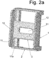
Figure 2a represents a general schematic view of the shield that is the subject of the invention as an alternative example of its realization which includes an additional panel (3). -
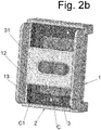
Figure 2b represents a general schematic view similar toFigure 2a , incorporated on a keypad lock (C). -
Figure 2c represents a general schematic view similar toFigure 2a , with the basic components ready for assembly as an example of its realisation. - An example of the practical realisation of this invention is described below, but not limited to it. Other modes of realisation would not be ruled out at all in which changes of accessories that do not undermine its purpose.
- The purpose of the invention is an optical shield for keypad locks, which consists of, at least, a frame (1) with one or several side panels (12) that project from the frame body (1) impeding the lateral view of the keypad for the lock (C) from a location near the user who is operating it.
- The cited frame (1) is provided with one or several structures (11) in which other standard structures (C1) fit, which keypads for locks (C) have as a series. The specific configuration/geometry of these structures (11), (C1), is indifferent for the effect of the invention and they can vary according to the different models/manufacturers existing in the market. It is basic for the effects of the invention that these structures fit different models without requiring any alteration in them, or in the lock or in its keypad (which are already installed and functioning).
- According to the represented realisation, the cited structures (11) have vertical grooves made in the back of the frame (1), situated in pairs and provided with some openings (11a) in one of its ends. The cited standard structures (C1) are first placed at the opening (11a) and then they are slid down along the form (11) until finally the frame (1) is positioned in the area of the keypad so that the side panels (12) that project from the body of the frame (1) impede the lateral view of the keypad from an area next to the user who is operating it.
- The cited frame (1) also has means (2) to fasten it indirectly to the lock module/keypad (C), without interfering with it.
- For the represented realisation, the cited means (2) are, at least, a plate (21) fastened to the frame (1) closing the structures (11) to impede the accidental or malicious removal of the frame (1).
- The mounting and fastening of the plate (21) in the frame (1) takes place, for example (see
figure 2c ), using a hole (22) lined up with another treaded blind hole made in the body of the frame (1); and having a tab (23) lined up with a recess made in the body of the frame (1). The fastening that impedes the undesired (accidental or malicious) removal of the shield that is the subject of the invention takes place inserting the tab (23) in the recess and inserting a safety screw (4) in the confronted holes. - The shield that is the subject of the invention, additionally, may have an additional panel (3) mounted on the frame (1) and is capable of sliding linearly in it. This additional panel (3) is provided with, at least, a window (31) through which one may access a restricted area of the keypad, impeding the frontal view of the rest.
- For the represented realisation example, this additional panel (3) is placed in its guide rails (13) made in the body of the frame (1) and specifically in the base area of the side panels (12). Along these guide rails (13) the panel (3) slides at the will of the user so that its window (31) is in front of a restricted area of the lock keypad (C) impeding the frontal view of the rest; in such a way that it is practically impossible to discover which keys the user is pressing at each moment.
- The materials, dimensions, proportions and, in general, those other accessory or secondary details may vary, as long as they do not alter, change or modify the proposed essential nature.
- The terms in which this report is prepared are true and the faithful reflection of the described object, and should be taken in their broadest sense and never in a limiting manner.
Claims (4)
- Optical shield for keypad locks, characterised in that it consists of:a) at least, a frame (1) provided with• at least one structure (11) into which standard structures (C1) fit which the lock keypads (C) have;• one or several side panels (12) that project from the frame body (1) impeding the lateral view of the lock keypad (C) from an area near the user who is operating it;b) means (2) to fasten indirectly the frame (1) to the lock module/keypad (C), without interfering with it.
- A shield, according to claim 1, characterised in that the cited structures (11) have grooves made in on its back and provided with some openings (11a) in one of its ends in order to position the cited standard structures (C1) in it.
- A shield, according to claim 1, characterised in that the cited means (2) for indirectly fastening the frame (1) to the lock (C) are, at least, a plate (21) fastened to the frame (1) closing the structures (11) to impede the accidental or malicious removal of the frame (1).
- A shield, according to above claims, characterised in that it has an additional panel (3) mounted on the frame (1) and capable of sliding linearly in it; with this additional panel (3) being provided with, at least, one window (31) through which a restricted area of the keypad is accessed, impeding the frontal view of the rest.
Applications Claiming Priority (1)
| Application Number | Priority Date | Filing Date | Title |
|---|---|---|---|
| ES201830289A ES2725306B2 (en) | 2018-03-23 | 2018-03-23 | Visual protector for keypad locks |
Publications (2)
| Publication Number | Publication Date |
|---|---|
| EP3543441A1 true EP3543441A1 (en) | 2019-09-25 |
| EP3543441B1 EP3543441B1 (en) | 2021-05-12 |
Family
ID=65991741
Family Applications (1)
| Application Number | Title | Priority Date | Filing Date |
|---|---|---|---|
| EP19382197.2A Active EP3543441B1 (en) | 2018-03-23 | 2019-03-20 | Optical shield for keypad locks |
Country Status (3)
| Country | Link |
|---|---|
| US (1) | US20190292810A1 (en) |
| EP (1) | EP3543441B1 (en) |
| ES (1) | ES2725306B2 (en) |
Cited By (1)
| Publication number | Priority date | Publication date | Assignee | Title |
|---|---|---|---|---|
| CN112377008A (en) * | 2020-11-13 | 2021-02-19 | 厦门市晗正电子有限公司 | Intelligent lock with virtual keyboard |
Citations (4)
| Publication number | Priority date | Publication date | Assignee | Title |
|---|---|---|---|---|
| EP0092048A2 (en) * | 1982-04-20 | 1983-10-26 | Siemens Nixdorf Informationssysteme Aktiengesellschaft | Data input device for an information processor |
| US20090218203A1 (en) * | 2005-05-06 | 2009-09-03 | Alistair Taverner | Keypad Shield |
| US20100172033A1 (en) * | 2006-03-28 | 2010-07-08 | Neil Radford | Keypad security device |
| GB2531714A (en) * | 2014-10-24 | 2016-05-04 | Espier Holdings Ltd | Keypad shield |
Family Cites Families (3)
| Publication number | Priority date | Publication date | Assignee | Title |
|---|---|---|---|---|
| JP5747652B2 (en) * | 2011-05-20 | 2015-07-15 | 沖電気工業株式会社 | Automatic transaction equipment, information processing terminal and peep prevention cover |
| ES1147183Y (en) * | 2015-10-22 | 2016-03-01 | Ojmar Sa | ELECTRONIC LOCK AND ELECTRONIC CLOSURE SYSTEM FOR FURNITURE, CABINETS OR LOCKS |
| CN205375623U (en) * | 2016-01-14 | 2016-07-06 | 吴刚 | Intelligence entrance guard anti -theft device |
-
2018
- 2018-03-23 ES ES201830289A patent/ES2725306B2/en not_active Expired - Fee Related
-
2019
- 2019-03-20 EP EP19382197.2A patent/EP3543441B1/en active Active
- 2019-03-22 US US16/361,903 patent/US20190292810A1/en not_active Abandoned
Patent Citations (4)
| Publication number | Priority date | Publication date | Assignee | Title |
|---|---|---|---|---|
| EP0092048A2 (en) * | 1982-04-20 | 1983-10-26 | Siemens Nixdorf Informationssysteme Aktiengesellschaft | Data input device for an information processor |
| US20090218203A1 (en) * | 2005-05-06 | 2009-09-03 | Alistair Taverner | Keypad Shield |
| US20100172033A1 (en) * | 2006-03-28 | 2010-07-08 | Neil Radford | Keypad security device |
| GB2531714A (en) * | 2014-10-24 | 2016-05-04 | Espier Holdings Ltd | Keypad shield |
Cited By (1)
| Publication number | Priority date | Publication date | Assignee | Title |
|---|---|---|---|---|
| CN112377008A (en) * | 2020-11-13 | 2021-02-19 | 厦门市晗正电子有限公司 | Intelligent lock with virtual keyboard |
Also Published As
| Publication number | Publication date |
|---|---|
| ES2725306B2 (en) | 2020-07-01 |
| ES2725306A1 (en) | 2019-09-23 |
| US20190292810A1 (en) | 2019-09-26 |
| EP3543441B1 (en) | 2021-05-12 |
Similar Documents
| Publication | Publication Date | Title |
|---|---|---|
| US9765550B2 (en) | Passive door lock mechanisms | |
| US6098433A (en) | Lock for safes and other security devices | |
| US4330146A (en) | Portable door lock | |
| US6925758B2 (en) | Forced entry resistance device for sash window assembly | |
| KR20080095832A (en) | Door security device | |
| US20140117681A1 (en) | Security Door Lock Device | |
| EP0835358A1 (en) | Bolt unit and frame arrangement | |
| EP2586951A1 (en) | Security safe and self-service terminal provided with same | |
| US20140311390A1 (en) | Safe and Lock Mechanism | |
| US20250230685A1 (en) | Assembly, system, and method for operatively associating a smart lock to a barrier | |
| US10557294B2 (en) | Multipoint door locking system | |
| EP3543441B1 (en) | Optical shield for keypad locks | |
| US5280976A (en) | Door security device | |
| KR102133349B1 (en) | Door lock device applicable for door type and drawer type cabinet | |
| EP3918162B1 (en) | Closing device for windows and doors | |
| GB2407615A (en) | Security chain with mechanical lock and manual release | |
| US20070029823A1 (en) | Retrofittable reinforced door jamb plate | |
| CN215565045U (en) | Panel structure of indoor door lock | |
| US7003992B1 (en) | Door hinge deadbolt | |
| US20260110201A1 (en) | Apparatuses and methods for locking a door | |
| CA2560623C (en) | Panel lock for electronic, electrical or control cabinets | |
| EP1375785B1 (en) | Lock for doors and the like | |
| WO2020033994A1 (en) | Sliding body restrictor | |
| AU2014253559B2 (en) | A Lock | |
| WO2009060175A1 (en) | Locks for windows and doors |
Legal Events
| Date | Code | Title | Description |
|---|---|---|---|
| PUAI | Public reference made under article 153(3) epc to a published international application that has entered the european phase |
Free format text: ORIGINAL CODE: 0009012 |
|
| STAA | Information on the status of an ep patent application or granted ep patent |
Free format text: STATUS: THE APPLICATION HAS BEEN PUBLISHED |
|
| AK | Designated contracting states |
Kind code of ref document: A1 Designated state(s): AL AT BE BG CH CY CZ DE DK EE ES FI FR GB GR HR HU IE IS IT LI LT LU LV MC MK MT NL NO PL PT RO RS SE SI SK SM TR |
|
| AX | Request for extension of the european patent |
Extension state: BA ME |
|
| STAA | Information on the status of an ep patent application or granted ep patent |
Free format text: STATUS: REQUEST FOR EXAMINATION WAS MADE |
|
| 17P | Request for examination filed |
Effective date: 20200325 |
|
| RBV | Designated contracting states (corrected) |
Designated state(s): AL AT BE BG CH CY CZ DE DK EE ES FI FR GB GR HR HU IE IS IT LI LT LU LV MC MK MT NL NO PL PT RO RS SE SI SK SM TR |
|
| STAA | Information on the status of an ep patent application or granted ep patent |
Free format text: STATUS: EXAMINATION IS IN PROGRESS |
|
| 17Q | First examination report despatched |
Effective date: 20200624 |
|
| GRAP | Despatch of communication of intention to grant a patent |
Free format text: ORIGINAL CODE: EPIDOSNIGR1 |
|
| STAA | Information on the status of an ep patent application or granted ep patent |
Free format text: STATUS: GRANT OF PATENT IS INTENDED |
|
| INTG | Intention to grant announced |
Effective date: 20210118 |
|
| GRAS | Grant fee paid |
Free format text: ORIGINAL CODE: EPIDOSNIGR3 |
|
| GRAA | (expected) grant |
Free format text: ORIGINAL CODE: 0009210 |
|
| STAA | Information on the status of an ep patent application or granted ep patent |
Free format text: STATUS: THE PATENT HAS BEEN GRANTED |
|
| RIN1 | Information on inventor provided before grant (corrected) |
Inventor name: AGUIRREZABALA OLASAGASTI, JOSEBA JOKIN Inventor name: ZABALA ZABALETA, JON |
|
| AK | Designated contracting states |
Kind code of ref document: B1 Designated state(s): AL AT BE BG CH CY CZ DE DK EE ES FI FR GB GR HR HU IE IS IT LI LT LU LV MC MK MT NL NO PL PT RO RS SE SI SK SM TR |
|
| REG | Reference to a national code |
Ref country code: GB Ref legal event code: FG4D |
|
| REG | Reference to a national code |
Ref country code: CH Ref legal event code: EP |
|
| REG | Reference to a national code |
Ref country code: DE Ref legal event code: R096 Ref document number: 602019004596 Country of ref document: DE |
|
| REG | Reference to a national code |
Ref country code: IE Ref legal event code: FG4D |
|
| REG | Reference to a national code |
Ref country code: AT Ref legal event code: REF Ref document number: 1392269 Country of ref document: AT Kind code of ref document: T Effective date: 20210615 |
|
| REG | Reference to a national code |
Ref country code: LT Ref legal event code: MG9D |
|
| REG | Reference to a national code |
Ref country code: AT Ref legal event code: MK05 Ref document number: 1392269 Country of ref document: AT Kind code of ref document: T Effective date: 20210512 |
|
| REG | Reference to a national code |
Ref country code: NL Ref legal event code: MP Effective date: 20210512 |
|
| PG25 | Lapsed in a contracting state [announced via postgrant information from national office to epo] |
Ref country code: HR Free format text: LAPSE BECAUSE OF FAILURE TO SUBMIT A TRANSLATION OF THE DESCRIPTION OR TO PAY THE FEE WITHIN THE PRESCRIBED TIME-LIMIT Effective date: 20210512 Ref country code: LT Free format text: LAPSE BECAUSE OF FAILURE TO SUBMIT A TRANSLATION OF THE DESCRIPTION OR TO PAY THE FEE WITHIN THE PRESCRIBED TIME-LIMIT Effective date: 20210512 Ref country code: FI Free format text: LAPSE BECAUSE OF FAILURE TO SUBMIT A TRANSLATION OF THE DESCRIPTION OR TO PAY THE FEE WITHIN THE PRESCRIBED TIME-LIMIT Effective date: 20210512 Ref country code: BG Free format text: LAPSE BECAUSE OF FAILURE TO SUBMIT A TRANSLATION OF THE DESCRIPTION OR TO PAY THE FEE WITHIN THE PRESCRIBED TIME-LIMIT Effective date: 20210812 Ref country code: AT Free format text: LAPSE BECAUSE OF FAILURE TO SUBMIT A TRANSLATION OF THE DESCRIPTION OR TO PAY THE FEE WITHIN THE PRESCRIBED TIME-LIMIT Effective date: 20210512 |
|
| PG25 | Lapsed in a contracting state [announced via postgrant information from national office to epo] |
Ref country code: GR Free format text: LAPSE BECAUSE OF FAILURE TO SUBMIT A TRANSLATION OF THE DESCRIPTION OR TO PAY THE FEE WITHIN THE PRESCRIBED TIME-LIMIT Effective date: 20210813 Ref country code: IS Free format text: LAPSE BECAUSE OF FAILURE TO SUBMIT A TRANSLATION OF THE DESCRIPTION OR TO PAY THE FEE WITHIN THE PRESCRIBED TIME-LIMIT Effective date: 20210912 Ref country code: RS Free format text: LAPSE BECAUSE OF FAILURE TO SUBMIT A TRANSLATION OF THE DESCRIPTION OR TO PAY THE FEE WITHIN THE PRESCRIBED TIME-LIMIT Effective date: 20210512 Ref country code: SE Free format text: LAPSE BECAUSE OF FAILURE TO SUBMIT A TRANSLATION OF THE DESCRIPTION OR TO PAY THE FEE WITHIN THE PRESCRIBED TIME-LIMIT Effective date: 20210512 Ref country code: PT Free format text: LAPSE BECAUSE OF FAILURE TO SUBMIT A TRANSLATION OF THE DESCRIPTION OR TO PAY THE FEE WITHIN THE PRESCRIBED TIME-LIMIT Effective date: 20210913 Ref country code: NO Free format text: LAPSE BECAUSE OF FAILURE TO SUBMIT A TRANSLATION OF THE DESCRIPTION OR TO PAY THE FEE WITHIN THE PRESCRIBED TIME-LIMIT Effective date: 20210812 Ref country code: PL Free format text: LAPSE BECAUSE OF FAILURE TO SUBMIT A TRANSLATION OF THE DESCRIPTION OR TO PAY THE FEE WITHIN THE PRESCRIBED TIME-LIMIT Effective date: 20210512 Ref country code: LV Free format text: LAPSE BECAUSE OF FAILURE TO SUBMIT A TRANSLATION OF THE DESCRIPTION OR TO PAY THE FEE WITHIN THE PRESCRIBED TIME-LIMIT Effective date: 20210512 |
|
| PG25 | Lapsed in a contracting state [announced via postgrant information from national office to epo] |
Ref country code: NL Free format text: LAPSE BECAUSE OF FAILURE TO SUBMIT A TRANSLATION OF THE DESCRIPTION OR TO PAY THE FEE WITHIN THE PRESCRIBED TIME-LIMIT Effective date: 20210512 |
|
| PG25 | Lapsed in a contracting state [announced via postgrant information from national office to epo] |
Ref country code: EE Free format text: LAPSE BECAUSE OF FAILURE TO SUBMIT A TRANSLATION OF THE DESCRIPTION OR TO PAY THE FEE WITHIN THE PRESCRIBED TIME-LIMIT Effective date: 20210512 Ref country code: ES Free format text: LAPSE BECAUSE OF FAILURE TO SUBMIT A TRANSLATION OF THE DESCRIPTION OR TO PAY THE FEE WITHIN THE PRESCRIBED TIME-LIMIT Effective date: 20210512 Ref country code: SK Free format text: LAPSE BECAUSE OF FAILURE TO SUBMIT A TRANSLATION OF THE DESCRIPTION OR TO PAY THE FEE WITHIN THE PRESCRIBED TIME-LIMIT Effective date: 20210512 Ref country code: SM Free format text: LAPSE BECAUSE OF FAILURE TO SUBMIT A TRANSLATION OF THE DESCRIPTION OR TO PAY THE FEE WITHIN THE PRESCRIBED TIME-LIMIT Effective date: 20210512 Ref country code: RO Free format text: LAPSE BECAUSE OF FAILURE TO SUBMIT A TRANSLATION OF THE DESCRIPTION OR TO PAY THE FEE WITHIN THE PRESCRIBED TIME-LIMIT Effective date: 20210512 Ref country code: CZ Free format text: LAPSE BECAUSE OF FAILURE TO SUBMIT A TRANSLATION OF THE DESCRIPTION OR TO PAY THE FEE WITHIN THE PRESCRIBED TIME-LIMIT Effective date: 20210512 Ref country code: DK Free format text: LAPSE BECAUSE OF FAILURE TO SUBMIT A TRANSLATION OF THE DESCRIPTION OR TO PAY THE FEE WITHIN THE PRESCRIBED TIME-LIMIT Effective date: 20210512 |
|
| REG | Reference to a national code |
Ref country code: DE Ref legal event code: R097 Ref document number: 602019004596 Country of ref document: DE |
|
| PLBE | No opposition filed within time limit |
Free format text: ORIGINAL CODE: 0009261 |
|
| STAA | Information on the status of an ep patent application or granted ep patent |
Free format text: STATUS: NO OPPOSITION FILED WITHIN TIME LIMIT |
|
| 26N | No opposition filed |
Effective date: 20220215 |
|
| PG25 | Lapsed in a contracting state [announced via postgrant information from national office to epo] |
Ref country code: IS Free format text: LAPSE BECAUSE OF FAILURE TO SUBMIT A TRANSLATION OF THE DESCRIPTION OR TO PAY THE FEE WITHIN THE PRESCRIBED TIME-LIMIT Effective date: 20210912 Ref country code: AL Free format text: LAPSE BECAUSE OF FAILURE TO SUBMIT A TRANSLATION OF THE DESCRIPTION OR TO PAY THE FEE WITHIN THE PRESCRIBED TIME-LIMIT Effective date: 20210512 |
|
| PGFP | Annual fee paid to national office [announced via postgrant information from national office to epo] |
Ref country code: FR Payment date: 20220315 Year of fee payment: 4 |
|
| PG25 | Lapsed in a contracting state [announced via postgrant information from national office to epo] |
Ref country code: IT Free format text: LAPSE BECAUSE OF FAILURE TO SUBMIT A TRANSLATION OF THE DESCRIPTION OR TO PAY THE FEE WITHIN THE PRESCRIBED TIME-LIMIT Effective date: 20210512 |
|
| PG25 | Lapsed in a contracting state [announced via postgrant information from national office to epo] |
Ref country code: MC Free format text: LAPSE BECAUSE OF FAILURE TO SUBMIT A TRANSLATION OF THE DESCRIPTION OR TO PAY THE FEE WITHIN THE PRESCRIBED TIME-LIMIT Effective date: 20210512 |
|
| PGFP | Annual fee paid to national office [announced via postgrant information from national office to epo] |
Ref country code: DE Payment date: 20220829 Year of fee payment: 4 |
|
| REG | Reference to a national code |
Ref country code: CH Ref legal event code: PL |
|
| PGFP | Annual fee paid to national office [announced via postgrant information from national office to epo] |
Ref country code: BE Payment date: 20220727 Year of fee payment: 4 |
|
| PG25 | Lapsed in a contracting state [announced via postgrant information from national office to epo] |
Ref country code: LU Free format text: LAPSE BECAUSE OF NON-PAYMENT OF DUE FEES Effective date: 20220320 Ref country code: LI Free format text: LAPSE BECAUSE OF NON-PAYMENT OF DUE FEES Effective date: 20220331 Ref country code: IE Free format text: LAPSE BECAUSE OF NON-PAYMENT OF DUE FEES Effective date: 20220320 Ref country code: CH Free format text: LAPSE BECAUSE OF NON-PAYMENT OF DUE FEES Effective date: 20220331 |
|
| REG | Reference to a national code |
Ref country code: DE Ref legal event code: R119 Ref document number: 602019004596 Country of ref document: DE |
|
| GBPC | Gb: european patent ceased through non-payment of renewal fee |
Effective date: 20230320 |
|
| REG | Reference to a national code |
Ref country code: BE Ref legal event code: MM Effective date: 20230331 |
|
| PG25 | Lapsed in a contracting state [announced via postgrant information from national office to epo] |
Ref country code: GB Free format text: LAPSE BECAUSE OF NON-PAYMENT OF DUE FEES Effective date: 20230320 |
|
| PG25 | Lapsed in a contracting state [announced via postgrant information from national office to epo] |
Ref country code: GB Free format text: LAPSE BECAUSE OF NON-PAYMENT OF DUE FEES Effective date: 20230320 Ref country code: FR Free format text: LAPSE BECAUSE OF NON-PAYMENT OF DUE FEES Effective date: 20230331 Ref country code: DE Free format text: LAPSE BECAUSE OF NON-PAYMENT OF DUE FEES Effective date: 20231003 |
|
| PG25 | Lapsed in a contracting state [announced via postgrant information from national office to epo] |
Ref country code: BE Free format text: LAPSE BECAUSE OF NON-PAYMENT OF DUE FEES Effective date: 20230331 |
|
| PG25 | Lapsed in a contracting state [announced via postgrant information from national office to epo] |
Ref country code: MK Free format text: LAPSE BECAUSE OF FAILURE TO SUBMIT A TRANSLATION OF THE DESCRIPTION OR TO PAY THE FEE WITHIN THE PRESCRIBED TIME-LIMIT Effective date: 20210512 Ref country code: CY Free format text: LAPSE BECAUSE OF FAILURE TO SUBMIT A TRANSLATION OF THE DESCRIPTION OR TO PAY THE FEE WITHIN THE PRESCRIBED TIME-LIMIT Effective date: 20210512 |
|
| PG25 | Lapsed in a contracting state [announced via postgrant information from national office to epo] |
Ref country code: HU Free format text: LAPSE BECAUSE OF FAILURE TO SUBMIT A TRANSLATION OF THE DESCRIPTION OR TO PAY THE FEE WITHIN THE PRESCRIBED TIME-LIMIT; INVALID AB INITIO Effective date: 20190320 |
|
| PG25 | Lapsed in a contracting state [announced via postgrant information from national office to epo] |
Ref country code: TR Free format text: LAPSE BECAUSE OF FAILURE TO SUBMIT A TRANSLATION OF THE DESCRIPTION OR TO PAY THE FEE WITHIN THE PRESCRIBED TIME-LIMIT Effective date: 20210512 |
|
| PG25 | Lapsed in a contracting state [announced via postgrant information from national office to epo] |
Ref country code: MT Free format text: LAPSE BECAUSE OF FAILURE TO SUBMIT A TRANSLATION OF THE DESCRIPTION OR TO PAY THE FEE WITHIN THE PRESCRIBED TIME-LIMIT Effective date: 20210512 |