EP3543399A1 - Steel cord for reinforcing rubber articles and rubber crawler and tire using same - Google Patents
Steel cord for reinforcing rubber articles and rubber crawler and tire using same Download PDFInfo
- Publication number
- EP3543399A1 EP3543399A1 EP17872609.7A EP17872609A EP3543399A1 EP 3543399 A1 EP3543399 A1 EP 3543399A1 EP 17872609 A EP17872609 A EP 17872609A EP 3543399 A1 EP3543399 A1 EP 3543399A1
- Authority
- EP
- European Patent Office
- Prior art keywords
- core
- steel cord
- sheath
- filament
- filaments
- Prior art date
- Legal status (The legal status is an assumption and is not a legal conclusion. Google has not performed a legal analysis and makes no representation as to the accuracy of the status listed.)
- Withdrawn
Links
- 229910000831 Steel Inorganic materials 0.000 title claims abstract description 105
- 239000010959 steel Substances 0.000 title claims abstract description 105
- 230000003014 reinforcing effect Effects 0.000 title claims abstract description 24
- 230000000052 comparative effect Effects 0.000 description 8
- 238000010276 construction Methods 0.000 description 4
- 238000007796 conventional method Methods 0.000 description 3
- 230000035699 permeability Effects 0.000 description 3
- 239000012779 reinforcing material Substances 0.000 description 3
- 238000005491 wire drawing Methods 0.000 description 3
- 239000011324 bead Substances 0.000 description 2
- 230000000694 effects Effects 0.000 description 2
- JEIPFZHSYJVQDO-UHFFFAOYSA-N iron(III) oxide Inorganic materials O=[Fe]O[Fe]=O JEIPFZHSYJVQDO-UHFFFAOYSA-N 0.000 description 2
- 239000000463 material Substances 0.000 description 2
- 238000005259 measurement Methods 0.000 description 2
- 239000002184 metal Substances 0.000 description 2
- 239000000203 mixture Substances 0.000 description 2
- 230000002265 prevention Effects 0.000 description 2
- 230000001010 compromised effect Effects 0.000 description 1
- 230000007797 corrosion Effects 0.000 description 1
- 238000005260 corrosion Methods 0.000 description 1
- 230000003247 decreasing effect Effects 0.000 description 1
- 230000002542 deteriorative effect Effects 0.000 description 1
- 238000009792 diffusion process Methods 0.000 description 1
- 238000009434 installation Methods 0.000 description 1
- 238000004519 manufacturing process Methods 0.000 description 1
- 238000000465 moulding Methods 0.000 description 1
- 230000002093 peripheral effect Effects 0.000 description 1
- 238000013040 rubber vulcanization Methods 0.000 description 1
- XLYOFNOQVPJJNP-UHFFFAOYSA-N water Substances O XLYOFNOQVPJJNP-UHFFFAOYSA-N 0.000 description 1
Images

Classifications
-
- D—TEXTILES; PAPER
- D07—ROPES; CABLES OTHER THAN ELECTRIC
- D07B—ROPES OR CABLES IN GENERAL
- D07B1/00—Constructional features of ropes or cables
- D07B1/06—Ropes or cables built-up from metal wires, e.g. of section wires around a hemp core
- D07B1/0606—Reinforcing cords for rubber or plastic articles
- D07B1/0613—Reinforcing cords for rubber or plastic articles the reinforcing cords being characterised by the rope configuration
-
- B—PERFORMING OPERATIONS; TRANSPORTING
- B60—VEHICLES IN GENERAL
- B60C—VEHICLE TYRES; TYRE INFLATION; TYRE CHANGING; CONNECTING VALVES TO INFLATABLE ELASTIC BODIES IN GENERAL; DEVICES OR ARRANGEMENTS RELATED TO TYRES
- B60C9/00—Reinforcements or ply arrangement of pneumatic tyres
-
- D—TEXTILES; PAPER
- D07—ROPES; CABLES OTHER THAN ELECTRIC
- D07B—ROPES OR CABLES IN GENERAL
- D07B1/00—Constructional features of ropes or cables
- D07B1/06—Ropes or cables built-up from metal wires, e.g. of section wires around a hemp core
- D07B1/0606—Reinforcing cords for rubber or plastic articles
- D07B1/062—Reinforcing cords for rubber or plastic articles the reinforcing cords being characterised by the strand configuration
-
- D—TEXTILES; PAPER
- D07—ROPES; CABLES OTHER THAN ELECTRIC
- D07B—ROPES OR CABLES IN GENERAL
- D07B1/00—Constructional features of ropes or cables
- D07B1/06—Ropes or cables built-up from metal wires, e.g. of section wires around a hemp core
- D07B1/0606—Reinforcing cords for rubber or plastic articles
- D07B1/062—Reinforcing cords for rubber or plastic articles the reinforcing cords being characterised by the strand configuration
- D07B1/0626—Reinforcing cords for rubber or plastic articles the reinforcing cords being characterised by the strand configuration the reinforcing cords consisting of three core wires or filaments and at least one layer of outer wires or filaments, i.e. a 3+N configuration
-
- D—TEXTILES; PAPER
- D07—ROPES; CABLES OTHER THAN ELECTRIC
- D07B—ROPES OR CABLES IN GENERAL
- D07B1/00—Constructional features of ropes or cables
- D07B1/06—Ropes or cables built-up from metal wires, e.g. of section wires around a hemp core
- D07B1/0606—Reinforcing cords for rubber or plastic articles
- D07B1/062—Reinforcing cords for rubber or plastic articles the reinforcing cords being characterised by the strand configuration
- D07B1/0633—Reinforcing cords for rubber or plastic articles the reinforcing cords being characterised by the strand configuration having a multiple-layer configuration
-
- D—TEXTILES; PAPER
- D07—ROPES; CABLES OTHER THAN ELECTRIC
- D07B—ROPES OR CABLES IN GENERAL
- D07B2201/00—Ropes or cables
- D07B2201/10—Rope or cable structures
- D07B2201/1012—Rope or cable structures characterised by their internal structure
- D07B2201/102—Rope or cable structures characterised by their internal structure including a core
-
- D—TEXTILES; PAPER
- D07—ROPES; CABLES OTHER THAN ELECTRIC
- D07B—ROPES OR CABLES IN GENERAL
- D07B2201/00—Ropes or cables
- D07B2201/10—Rope or cable structures
- D07B2201/1092—Parallel strands
-
- D—TEXTILES; PAPER
- D07—ROPES; CABLES OTHER THAN ELECTRIC
- D07B—ROPES OR CABLES IN GENERAL
- D07B2201/00—Ropes or cables
- D07B2201/20—Rope or cable components
- D07B2201/2001—Wires or filaments
- D07B2201/2006—Wires or filaments characterised by a value or range of the dimension given
-
- D—TEXTILES; PAPER
- D07—ROPES; CABLES OTHER THAN ELECTRIC
- D07B—ROPES OR CABLES IN GENERAL
- D07B2201/00—Ropes or cables
- D07B2201/20—Rope or cable components
- D07B2201/2015—Strands
- D07B2201/2016—Strands characterised by their cross-sectional shape
- D07B2201/2018—Strands characterised by their cross-sectional shape oval
-
- D—TEXTILES; PAPER
- D07—ROPES; CABLES OTHER THAN ELECTRIC
- D07B—ROPES OR CABLES IN GENERAL
- D07B2201/00—Ropes or cables
- D07B2201/20—Rope or cable components
- D07B2201/2015—Strands
- D07B2201/2023—Strands with core
-
- D—TEXTILES; PAPER
- D07—ROPES; CABLES OTHER THAN ELECTRIC
- D07B—ROPES OR CABLES IN GENERAL
- D07B2201/00—Ropes or cables
- D07B2201/20—Rope or cable components
- D07B2201/2047—Cores
- D07B2201/2048—Cores characterised by their cross-sectional shape
-
- D—TEXTILES; PAPER
- D07—ROPES; CABLES OTHER THAN ELECTRIC
- D07B—ROPES OR CABLES IN GENERAL
- D07B2201/00—Ropes or cables
- D07B2201/20—Rope or cable components
- D07B2201/2047—Cores
- D07B2201/2051—Cores characterised by a value or range of the dimension given
-
- D—TEXTILES; PAPER
- D07—ROPES; CABLES OTHER THAN ELECTRIC
- D07B—ROPES OR CABLES IN GENERAL
- D07B2201/00—Ropes or cables
- D07B2201/20—Rope or cable components
- D07B2201/2047—Cores
- D07B2201/2052—Cores characterised by their structure
- D07B2201/2059—Cores characterised by their structure comprising wires
- D07B2201/206—Cores characterised by their structure comprising wires arranged parallel to the axis
-
- D—TEXTILES; PAPER
- D07—ROPES; CABLES OTHER THAN ELECTRIC
- D07B—ROPES OR CABLES IN GENERAL
- D07B2201/00—Ropes or cables
- D07B2201/20—Rope or cable components
- D07B2201/2047—Cores
- D07B2201/2066—Cores characterised by the materials used
-
- D—TEXTILES; PAPER
- D07—ROPES; CABLES OTHER THAN ELECTRIC
- D07B—ROPES OR CABLES IN GENERAL
- D07B2201/00—Ropes or cables
- D07B2201/20—Rope or cable components
- D07B2201/2047—Cores
- D07B2201/2067—Cores characterised by the elongation or tension behaviour
- D07B2201/2068—Cores characterised by the elongation or tension behaviour having a load bearing function
-
- D—TEXTILES; PAPER
- D07—ROPES; CABLES OTHER THAN ELECTRIC
- D07B—ROPES OR CABLES IN GENERAL
- D07B2205/00—Rope or cable materials
- D07B2205/30—Inorganic materials
- D07B2205/3021—Metals
- D07B2205/3025—Steel
-
- D—TEXTILES; PAPER
- D07—ROPES; CABLES OTHER THAN ELECTRIC
- D07B—ROPES OR CABLES IN GENERAL
- D07B2401/00—Aspects related to the problem to be solved or advantage
- D07B2401/20—Aspects related to the problem to be solved or advantage related to ropes or cables
- D07B2401/2055—Improving load capacity
-
- D—TEXTILES; PAPER
- D07—ROPES; CABLES OTHER THAN ELECTRIC
- D07B—ROPES OR CABLES IN GENERAL
- D07B2401/00—Aspects related to the problem to be solved or advantage
- D07B2401/20—Aspects related to the problem to be solved or advantage related to ropes or cables
- D07B2401/208—Enabling filler penetration
-
- D—TEXTILES; PAPER
- D07—ROPES; CABLES OTHER THAN ELECTRIC
- D07B—ROPES OR CABLES IN GENERAL
- D07B2501/00—Application field
- D07B2501/20—Application field related to ropes or cables
- D07B2501/2046—Tyre cords
Definitions
- the present invention relates to a steel cord for reinforcing rubber articles (hereinafter, also simply referred to as "steel cord”), a rubber crawler and a tire using the steel cord, and more specifically, to a steel cord for reinforcing rubber articles, which can prevent a reduction in the strength of the steel cord by twisting steel filaments, and a rubber crawler and a tire using the steel cord.
- steel cord for reinforcing rubber articles
- an endless rubber crawler typically, a large tension is applied to an endless rubber crawler when it is attached to a vehicle or the like and used. For this reason, steel cords as tensile bodies are embedded in such a rubber crawler in a row along the longitudinal direction thereof.
- Such an endless rubber crawler is usually manufactured by preparing an open-ended rubber crawler base body in which steel cords are embedded, superimposing the steel cords protruding from both ends thereof, and further subjecting the overlapped portion (endless site) to rubber vulcanization.
- Patent Document 1 proposes a steel cord in which two core filaments are aligned without being twisted and a sheath filament is twisted therearound, wherein the diameter of the core filament, the diameter of the sheath filament, and the twist pitch of the sheath filament are optimized to achieve both rubber permeability and productivity.
- a steel cord having a core which is two core filaments aligned without being twisted like the steel cord proposed in Patent Document 1 is excellent in permeation of rubber into the inside thereof, and diffusion of rust or the like from a place where a cut damage is given can be suppressed.
- a steel cord having a multi-twisted structure comprising: a steel cord having the structure proposed in Patent Document 1 as a core strand; and a plurality of sheath strands wound therearound is employed as a reinforcing material for construction vehicle tires, rubber crawlers, or the like, an assumed strength cannot be obtained. In other words, the strength of the steel cord has decreased to 90% or less (so-called twisting loss) with respect to the sum of the strengths of filaments constituting the steel cord, each filament being not twisted.
- an object of the present invention is to provide a steel cord for reinforcing rubber articles, which can prevent a reduction in the strength of the steel cord caused by twisting steel filaments, and a rubber crawler and a tire using the steel cord.
- the present inventors intensively studied to obtain the following findings. That is, when the twist of a multi-twisted steel cord having a core strand of 2+m structure as a core strand was relaxed to measure the strength of each strand, an assumed strength was obtained in each strand. However, it has become clear that preceding breakage of a core filament of a core strand occurs in a multi-twisted steel cord. Based on such findings, the present inventors further intensively studied to find that, by making the diameter and the tensile strength of each steel filament constituting a core strand predetermined ones, preceding breakage of a core filament of the core strand can be prevented, which can solve the above-described problems, thereby completing the present invention.
- a steel cord for reinforcing rubber articles is a steel cord for reinforcing rubber articles formed by twisting a plurality of sheath strands in which a plurality of steel filaments are twisted around a core strand in which a plurality of steel filaments are twisted, characterized in that the core strand comprises: a core composed of two core filaments aligned in parallel without being twisted; and at least one sheath composed of a plurality of sheath filaments twisted around the core, and a diameter dc of the core filament and a diameter ds of the sheath filament satisfy the following expression (1): dc ⁇ ds and the tensile strength T (MPa) of the core filament satisfies the relationship represented by the following expression (2): T ⁇ 3650 ⁇ 17000 ⁇ dc ⁇ 0.15 2
- the structure of the core strand is preferably a structure comprising a core composed of two core filaments and a first sheath composed of m sheath filaments formed around the core, or a structure comprising a core composed of two core filaments, a first sheath composed of m sheath filaments formed around the core, and a second sheath composed of n sheath filaments formed around the first sheath, where m is from 5 to 7 and n is from 10 to 15. That is, preferably, the structure of the core strand is 2+m structure or 2+m+n structure, where m is from 5 to 7, and n is from 10 to 15.
- the diameter dc of the core filament is from 0.15 to 0.40 mm.
- the tensile strength T of the core filament is 2,500 MPa or more.
- the diameter dc of the core strand and the diameter ds of the sheath filament satisfy the relationship represented by the following expression (3): dc > 0.5 ⁇ ds
- a rubber crawler according to the present invention is a rubber crawler characterized by being formed by using the steel cord caused for reinforcing rubber articles according to the present invention.
- a tire according to the present invention is a tire characterized by being formed by using the steel cord for reinforcing rubber articles according to the present invention.
- a steel cord for reinforcing rubber articles which can prevent a reduction in the strength of the steel cord by twisting steel filaments, and a rubber crawler and a tire using the steel cord can be provided.
- FIG. 1 is a cross-sectional view of a steel cord for reinforcing rubber articles according to one suitable embodiment of the present invention.
- a steel cord 1 of the present invention has a multi-twisted structure in which a plurality of sheath strands 3 in which a plurality of steel filaments are twisted are twisted around a core strand 2 in which a plurality of steel filaments are twisted.
- six sheath strands 3 are twisted around one core strand 2
- the structure of a steel cord of the present invention is not limited thereto, and for example, the number of sheath strands may be from 6 to 10.
- the core strand 2 comprises a core composed of two core filaments 2a aligned in parallel without being twisted and at least one sheath composed of a plurality of sheath filaments 2b twisted around the core.
- the structure of the core strand 2 is preferably a structure composed of a core composed of two core filaments 2a and a first sheath composed of m sheath filaments 2b formed around the core, or a structure composed of a core composed of two core filaments 2a, a first sheath composed of m sheath filaments 2b formed around the core, and a second sheath composed of n sheath filaments 2b formed around the first sheath, where m is 5 to 7 and n is 10 to 15.
- the core strand 2 has a 2+6 structure.
- productivity of a steel cord is not compromised and sufficient strength can be obtained.
- the diameter dc of a core filament 2a of the core strand 2 and the diameter ds of a sheath filament 2b satisfy the following expression (1): dc ⁇ ds or preferably, the following expression (4): dc ⁇ 0.92 ⁇ ds
- the roundness of the final multi-twisted steel cord deteriorates and the cross section of the cord becomes elliptical.
- the steel cord passes through a complicated path in a processing step, the steel cord is twisted halfway and a molding operation of the product deteriorates.
- the diameter dc of the core filament 2a of the core strand 2 and the diameter ds of the sheath filament 2b satisfy the following expression (3): dc > 0.5 ⁇ ds
- the tensile strength T (MPa) of the core filament 2a constituting the core strand 2 needs to satisfy a relationship represented by the following expression (2): T ⁇ 3650 ⁇ 17000 ⁇ dc ⁇ 0.15 2
- the diameter dc of the core filament 2a of the core strand 2 is preferably in the range of from 0.15 to 0.40 mm, more preferably from 0.15 to 0.35 mm, and further preferably from 0.15 to 0.33 mm.
- the diameter dc of the core filament 2a of the core strand 2 is in the above range, the effect of the present invention can be favorably obtained without deteriorating the productivity of the steel cord.
- the tensile strength T of the core filament 2a of the core strand 2 is preferably 2,500 MPa or more. This is because when the tensile strength T of the core filament 2a of the core strand 2 is less than 2,500 MPa, a strength of the finally obtained steel cord is not sufficient in some cases.
- the tensile strength T of the steel filament can be adjusted by changing the wire drawing conditions. For example, when processing distortion of a steel filament at a time of wire drawing is reduced, a steel filament with a small tensile strength T can be obtained.
- the twist pitch and twist direction of the sheath filaments 2b constituting the core strand 2 can be appropriately selected according to a conventional method.
- a sheath strand 3 has a 1+6 structure in which six sheath filaments 3b are twisted around one core filament 3a
- the structure of the sheath strand 3 is not particularly limited. A 3+9, 3+9+15, 1+6+12 structure or the like other than the 1+6 structure may be employed.
- the diameter of the core filament 3a and the diameter of the sheath filament 3b constituting the sheath strand 3 may be the same or different, and further, the twist pitch and twist direction of the sheath filaments 3b constituting the sheath strand 3 can also be appropriately selected according to a conventional method. Still further, the twist direction, the twist pitch and the like of the strand are also not particularly limited, and can be appropriately selected according to a conventional method.
- a rubber crawler of the present invention is a rubber crawler using a steel cord for reinforcing rubber articles of the present invention.
- FIG. 2 is a cross-sectional view in the width direction of a rubber crawler according to one suitable embodiment of the present invention.
- a steel cord 1 of the present invention which is a reinforcing material is coated with a treat rubber 11, and some of a metal core 14 having a detachment prevention protrusion 12 and a wing portion 13 on the inner peripheral surface side is embedded in a rubber member 16 formed with a lug 15 on an installation surface side.
- the steel cord 1 of the present invention is used as a tensile body, for other structures and the material of each member, those commonly used may be appropriately adopted, and they should not be particularly limited.
- the same rubber composition as that of a treat rubber 11 may be adopted as a rubber composition forming a rubber member 16, and in this case, the thickness of the treat rubber 11 may be appropriately selected to arrange the rubber member 16 while considering a thickness formed by the rubber member 16.
- a tire of the present invention is a tire using a steel cord for reinforcing rubber articles of the present invention.
- the steel cord of the present invention can be used as a reinforcing material for a carcass ply or a belt. Since the steel cord of the present invention has a multi-twisted structure and the core strand is excellent in rubber permeability, the steel cord can be suitably used for large tires or the like for off-road use such as tires for construction vehicles traveling on a wasteland.
- FIG. 3 is one side cross-sectional view of a tire according to one suitable embodiment of the present invention.
- the illustrated tire 20 is a construction vehicle tire comprising: a carcass 22 composed of a ply extending in the radial direction between a pair of bead cores 21; a belt 23 composed of at least two (six in the illustrated example) belt layers arranged on the outer side in the tire radial direction of a crown portion of the carcass 22; and a tread 24 arranged on the outer side in the tire radial direction of the belt 23.
- the steel cord 1 of the present invention is used as a reinforcing member, for other tire structures and the material of each member, those commonly used may be appropriately adopted, and they are not particularly limited.
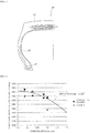
- FIG. 4 is a graph illustrating an expression (2) and relationships between diameters dc and tensile strengths of core filaments of core strands of Examples and Comparative Examples. Measurement of the strength of the steel cords and measurement of the tensile strength of the steel filaments constituting the steel cords were carried out in accordance with JIS G 3510. The tensile strength T of the steel filaments was adjusted by controlling the wire drawing conditions. For each prepared steel cord, the twisting loss and presence or absence of a preceding breakage of a core filament of a core strand were evaluated. A calculation expression of the twisting loss is as follows.
- the sum of filament strength is a total value of strengths of filaments constituting the steel cord, each filament not being twisted.
- Example 1 Comparative Example 2
- Example 2 Structure 2 ⁇ 0.28+6 ⁇ 0.36+6 ⁇ (0.36+6 ⁇ 0.33) 2 ⁇ 0.30+6 ⁇ 0.36+6 ⁇ (0.36+6 ⁇ 0.33) Twist pitch Core strand ⁇ /S18 ⁇ /S18 Sheath strand ⁇ /S18 ⁇ /S18 Cord ⁇ /S32.4 ⁇ /S32.4 Strength Cord strength (N) 11809 13120 12841 13209 Sum of filament strength (N) 14324 14302 14366 14282 Filament strength (N) 0.185 (mm) - - - - 0.225 (mm) - - - - 0.26 (mm) - - - - 0.28 (mm) 214 203 - - 0.30 (mm) - - 235 193 0.33 (mm) 279 279 279 279 0.36
Landscapes
- Engineering & Computer Science (AREA)
- Mechanical Engineering (AREA)
- Ropes Or Cables (AREA)
- Tires In General (AREA)
Abstract


Description
- The present invention relates to a steel cord for reinforcing rubber articles (hereinafter, also simply referred to as "steel cord"), a rubber crawler and a tire using the steel cord, and more specifically, to a steel cord for reinforcing rubber articles, which can prevent a reduction in the strength of the steel cord by twisting steel filaments, and a rubber crawler and a tire using the steel cord.
- Typically, a large tension is applied to an endless rubber crawler when it is attached to a vehicle or the like and used. For this reason, steel cords as tensile bodies are embedded in such a rubber crawler in a row along the longitudinal direction thereof. Such an endless rubber crawler is usually manufactured by preparing an open-ended rubber crawler base body in which steel cords are embedded, superimposing the steel cords protruding from both ends thereof, and further subjecting the overlapped portion (endless site) to rubber vulcanization.
- When such a rubber crawler receives an external damage enough to reach a steel cord, moisture flows through a portion where rubber is not permeated by capillary phenomenon, and rust may be caused by corrosion of the steel cord with water. In order to solve such a problem, conventionally, sufficient permeation of rubber inside a steel cord has been carried out. For example,
Patent Document 1 proposes a steel cord in which two core filaments are aligned without being twisted and a sheath filament is twisted therearound, wherein the diameter of the core filament, the diameter of the sheath filament, and the twist pitch of the sheath filament are optimized to achieve both rubber permeability and productivity. -
PATENT DOCUMENT 1 Japanese Unexamined Patent Application Publication No.2012-127028 - A steel cord having a core which is two core filaments aligned without being twisted like the steel cord proposed in
Patent Document 1 is excellent in permeation of rubber into the inside thereof, and diffusion of rust or the like from a place where a cut damage is given can be suppressed. However, when a steel cord having a multi-twisted structure comprising: a steel cord having the structure proposed inPatent Document 1 as a core strand; and a plurality of sheath strands wound therearound is employed as a reinforcing material for construction vehicle tires, rubber crawlers, or the like, an assumed strength cannot be obtained. In other words, the strength of the steel cord has decreased to 90% or less (so-called twisting loss) with respect to the sum of the strengths of filaments constituting the steel cord, each filament being not twisted. - Accordingly, an object of the present invention is to provide a steel cord for reinforcing rubber articles, which can prevent a reduction in the strength of the steel cord caused by twisting steel filaments, and a rubber crawler and a tire using the steel cord.
- In order to solve the above-described problems, the present inventors intensively studied to obtain the following findings. That is, when the twist of a multi-twisted steel cord having a core strand of 2+m structure as a core strand was relaxed to measure the strength of each strand, an assumed strength was obtained in each strand. However, it has become clear that preceding breakage of a core filament of a core strand occurs in a multi-twisted steel cord. Based on such findings, the present inventors further intensively studied to find that, by making the diameter and the tensile strength of each steel filament constituting a core strand predetermined ones, preceding breakage of a core filament of the core strand can be prevented, which can solve the above-described problems, thereby completing the present invention.
- Specifically, a steel cord for reinforcing rubber articles according to the present invention is a steel cord for reinforcing rubber articles formed by twisting a plurality of sheath strands in which a plurality of steel filaments are twisted around a core strand in which a plurality of steel filaments are twisted, characterized in that
the core strand comprises: a core composed of two core filaments aligned in parallel without being twisted; and at least one sheath composed of a plurality of sheath filaments twisted around the core, and
a diameter dc of the core filament and a diameter ds of the sheath filament satisfy the following expression (1):

- In the steel cord according to the present invention, the structure of the core strand is preferably a structure comprising a core composed of two core filaments and a first sheath composed of m sheath filaments formed around the core, or a structure comprising a core composed of two core filaments, a first sheath composed of m sheath filaments formed around the core, and a second sheath composed of n sheath filaments formed around the first sheath, where m is from 5 to 7 and n is from 10 to 15. That is, preferably, the structure of the core strand is 2+m structure or 2+m+n structure, where m is from 5 to 7, and n is from 10 to 15. In the steel cord according to the present invention, preferably, the diameter dc of the core filament is from 0.15 to 0.40 mm. Further, in the steel cord according to the present invention, preferably, the tensile strength T of the core filament is 2,500 MPa or more. Still further, in the steel cord according to the present invention, preferably, the diameter dc of the core strand and the diameter ds of the sheath filament satisfy the relationship represented by the following expression (3):

- A rubber crawler according to the present invention is a rubber crawler characterized by being formed by using the steel cord caused for reinforcing rubber articles according to the present invention.
- A tire according to the present invention is a tire characterized by being formed by using the steel cord for reinforcing rubber articles according to the present invention.
- According to the present invention, a steel cord for reinforcing rubber articles, which can prevent a reduction in the strength of the steel cord by twisting steel filaments, and a rubber crawler and a tire using the steel cord can be provided.
-
-
FIG. 1 is a cross-sectional view of a steel cord for reinforcing rubber articles according to one suitable embodiment of the present invention. -
FIG. 2 is a cross-sectional view in the width direction of a rubber crawler according to one suitable embodiment of the present invention. -
FIG. 3 is one side cross-sectional view of a tire according to one suitable embodiment of the present invention. -
FIG. 4 is a graph illustrating an expression (2) and relationships between diameters dc and tensile strengths of core filaments of core strands of Examples and Comparative Examples. - Hereinafter, a steel cord for reinforcing rubber articles of the present invention will be described in detail with reference to the drawings.
FIG. 1 is a cross-sectional view of a steel cord for reinforcing rubber articles according to one suitable embodiment of the present invention. Asteel cord 1 of the present invention has a multi-twisted structure in which a plurality ofsheath strands 3 in which a plurality of steel filaments are twisted are twisted around acore strand 2 in which a plurality of steel filaments are twisted. Although, in the illustrated example, sixsheath strands 3 are twisted around onecore strand 2, the structure of a steel cord of the present invention is not limited thereto, and for example, the number of sheath strands may be from 6 to 10. - In the
steel cord 1 of the present invention, thecore strand 2 comprises a core composed of twocore filaments 2a aligned in parallel without being twisted and at least one sheath composed of a plurality ofsheath filaments 2b twisted around the core. In thesteel cord 1 of the present invention, the structure of thecore strand 2 is preferably a structure composed of a core composed of twocore filaments 2a and a first sheath composed ofm sheath filaments 2b formed around the core, or a structure composed of a core composed of twocore filaments 2a, a first sheath composed ofm sheath filaments 2b formed around the core, and a second sheath composed ofn sheath filaments 2b formed around the first sheath, where m is 5 to 7 and n is 10 to 15. That is, preferably, a 2+m structure or a 2+m+n structure, where m is from 5 to 7, and n is from 10 to 15, and in the illustratedsteel cord 1, thecore strand 2 has a 2+6 structure. When the structure of thecore strand 2 has such a structure, productivity of a steel cord is not compromised and sufficient strength can be obtained. - In the steel cord of the present invention, the diameter dc of a
core filament 2a of thecore strand 2 and the diameter ds of asheath filament 2b satisfy the following expression (1):

- As the diameter of the
core filament 2a of thecore strand 2 is closer to the diameter of thesheath filament 2b of thecore strand 2, the roundness of the final multi-twisted steel cord deteriorates and the cross section of the cord becomes elliptical. In cases in which such a steel cord having poor roundness is used to manufacture a product, when the steel cord passes through a complicated path in a processing step, the steel cord is twisted halfway and a molding operation of the product deteriorates. - Further, in the
steel cord 1 of the present invention, the diameter dc of thecore filament 2a of thecore strand 2 and the diameter ds of thesheath filament 2b satisfy the following expression (3):
- When the diameter of the
core filament 2a becomes too small, the core becomes small, and therefore, a gap between thesheath filaments 2b becomes small and the rubber permeability of thecore strand 2 may deteriorate. - Still further, in a
steel cord 1 of the present invention, the tensile strength T (MPa) of thecore filament 2a constituting thecore strand 2 needs to satisfy a relationship represented by the following expression (2):
- By using the steel filament satisfying such requirements for the
core filament 2a of thecore strand 2, preceding breakage of thecore filament 2a can be prevented. - When the diameter dc of the
core filament 2a of thecore strand 2 is large, in order to satisfy the relationship of the above expression (2), the tensile strength of thecore filament 2a must be reduced, which increases the risk of preceding breakage of thecore filament 2a and may increase the twisting loss. Accordingly, in thesteel cord 1 of the present invention, the diameter dc of thecore filament 2a of thecore strand 2 is preferably in the range of from 0.15 to 0.40 mm, more preferably from 0.15 to 0.35 mm, and further preferably from 0.15 to 0.33 mm. When the diameter dc of thecore filament 2a of thecore strand 2 is in the above range, the effect of the present invention can be favorably obtained without deteriorating the productivity of the steel cord. - In the
steel cord 1 of the present invention, the tensile strength T of thecore filament 2a of thecore strand 2 is preferably 2,500 MPa or more. This is because when the tensile strength T of thecore filament 2a of thecore strand 2 is less than 2,500 MPa, a strength of the finally obtained steel cord is not sufficient in some cases. The tensile strength T of the steel filament can be adjusted by changing the wire drawing conditions. For example, when processing distortion of a steel filament at a time of wire drawing is reduced, a steel filament with a small tensile strength T can be obtained. - It is important for the
steel cord 1 of the present invention to satisfy the above requirements, and there is no other particular limitations on thesteel cord 1. For example, the twist pitch and twist direction of thesheath filaments 2b constituting thecore strand 2 can be appropriately selected according to a conventional method. Although in the illustrated example, asheath strand 3 has a 1+6 structure in which sixsheath filaments 3b are twisted around onecore filament 3a, in thesteel cord 1 of the present invention, the structure of thesheath strand 3 is not particularly limited. A 3+9, 3+9+15, 1+6+12 structure or the like other than the 1+6 structure may be employed. - The diameter of the
core filament 3a and the diameter of thesheath filament 3b constituting thesheath strand 3 may be the same or different, and further, the twist pitch and twist direction of thesheath filaments 3b constituting thesheath strand 3 can also be appropriately selected according to a conventional method. Still further, the twist direction, the twist pitch and the like of the strand are also not particularly limited, and can be appropriately selected according to a conventional method. - Next, a rubber crawler of the present invention will be described.
- A rubber crawler of the present invention is a rubber crawler using a steel cord for reinforcing rubber articles of the present invention.
FIG. 2 is a cross-sectional view in the width direction of a rubber crawler according to one suitable embodiment of the present invention. In the illustratedrubber crawler 10, asteel cord 1 of the present invention which is a reinforcing material is coated with atreat rubber 11, and some of ametal core 14 having adetachment prevention protrusion 12 and awing portion 13 on the inner peripheral surface side is embedded in arubber member 16 formed with alug 15 on an installation surface side. - In the
rubber crawler 10 of the present invention, as long as thesteel cord 1 of the present invention is used as a tensile body, for other structures and the material of each member, those commonly used may be appropriately adopted, and they should not be particularly limited. For example, the same rubber composition as that of atreat rubber 11 may be adopted as a rubber composition forming arubber member 16, and in this case, the thickness of thetreat rubber 11 may be appropriately selected to arrange therubber member 16 while considering a thickness formed by therubber member 16. - Next, a tire according to the present invention will be described.
- A tire of the present invention is a tire using a steel cord for reinforcing rubber articles of the present invention. For example, the steel cord of the present invention can be used as a reinforcing material for a carcass ply or a belt. Since the steel cord of the present invention has a multi-twisted structure and the core strand is excellent in rubber permeability, the steel cord can be suitably used for large tires or the like for off-road use such as tires for construction vehicles traveling on a wasteland.
-
FIG. 3 is one side cross-sectional view of a tire according to one suitable embodiment of the present invention. The illustratedtire 20 is a construction vehicle tire comprising: acarcass 22 composed of a ply extending in the radial direction between a pair ofbead cores 21; abelt 23 composed of at least two (six in the illustrated example) belt layers arranged on the outer side in the tire radial direction of a crown portion of thecarcass 22; and atread 24 arranged on the outer side in the tire radial direction of thebelt 23. In thetire 20 of the present invention, as long as thesteel cord 1 of the present invention is used as a reinforcing member, for other tire structures and the material of each member, those commonly used may be appropriately adopted, and they are not particularly limited. - Hereinafter, the present invention will be described in more detail by way of Examples.
- Steel cords having the structures listed on Tables 1 to 3 were prepared. The strengths of the steel cords and the tensile strength of a steel filament constituting the steel cord are as listed on the same tables, and
FIG. 4 is a graph illustrating an expression (2) and relationships between diameters dc and tensile strengths of core filaments of core strands of Examples and Comparative Examples. Measurement of the strength of the steel cords and measurement of the tensile strength of the steel filaments constituting the steel cords were carried out in accordance with JIS G 3510. The tensile strength T of the steel filaments was adjusted by controlling the wire drawing conditions. For each prepared steel cord, the twisting loss and presence or absence of a preceding breakage of a core filament of a core strand were evaluated. A calculation expression of the twisting loss is as follows. - The twisting loss (%) was calculated according to the following expression.

- Here, the sum of filament strength is a total value of strengths of filaments constituting the steel cord, each filament not being twisted.
[Table 1] Comparative Example 1 Example 1 Comparative Example 2 Example 2 Structure 

2×0.28+6×0.36+6×(0.36+6×0.33) 2×0.30+6×0.36+6×(0.36+6×0.33) Twist pitch Core strand ∞/S18 ∞/S18 Sheath strand ∞/S18 ∞/S18 Cord ∞/S32.4 ∞/S32.4 Strength Cord strength (N) 11809 13120 12841 13209 Sum of filament strength (N) 14324 14302 14366 14282 Filament strength (N) 0.185 (mm) - - - - 0.225 (mm) - - - - 0.26 (mm) - - - - 0.28 (mm) 214 203 - - 0.30 (mm) - - 235 193 0.33 (mm) 279 279 279 279 0.36 (mm) 321 321 321 321 Twisting loss (%) 18 8 11 8 Presence or absence of preceding breakage present absent present absent dc (mm) 0.28 0.28 0.30 0.30 3650 - 17000 × (dc - 0.15)2 3363 3363 3268 3268 Tensile strength of core filament (MPa) 3475 3297 3325 2730 [Table 2] Comparative Example 3 Example 3 Comparative Example 4 Example 4 Structure 

2×0.225+6×0.28+6×(0.28+6×0.26) 2×0.185+(6+11)×0.26+6×(0.36+6×0.33) Twist pitch Core strand ∞/S14 ∞/S11/Z18 Sheath strand ∞/S14 ∞/S18 Cord ∞/S25 ∞/S32.4 Strength Cord strength (N) 8045 8645 13552 14090 Sum of filament strength (N) 9408 9392 15264 15246 Filament strength (N) 0.185 (mm) - - 100 91 0.225 (mm) 144 136 - - 0.26 (mm) 182 182 182 182 0.28 (mm) 214 214 - - 0.3 (mm) - - - - 0.33 (mm) - - 279 279 0.36 (mm) - - 321 321 Twisting loss (%) 15 8 11 8 Presence or absence of preceding breakage present absent present absent dc (mm) 0.225 0.225 0.185 0.185 3650 - 17000 × (dc - 0.15)2 3554 3554 3629 3629 Tensile strength of core filament (MPa) 3622 3420 3720 3385 [Table 3] Comparative Example 5 Example 5 Structure 
2×0.30+6×0.36+6×(0.36+6×0.33) Twist pitch Core strand ∞/S18 Sheath strand ∞/S18 Cord ∞/S26.5 Strength Cord strength (N) 12552 12912 Sum of filament strength (N) 14366 14282 Filament strength (N) 0.185 (mm) - - 0.225 (mm) - - 0.26 (mm) - - 0.28 (mm) - - 0.30 (mm) 235 193 0.33 (mm) 279 279 0.36 (mm) 321 321 Twisting loss (%) 13 10 Presence or absence of preceding breakage present absent dc (mm) 0.30 0.30 3650 - 17000 × (dc - 0.15)2 3268 3268 Tensile strength of core filament (MPa) 3325 2730 - It is found from Tables 1 to 3 that in the steel cord of the present invention, the core filament of the core strand did not experience a preceding breakage and the twisting loss was small.
-
- 1
- steel cord
- 2
- core strand
- 2a
- core filament
- 2b
- sheath filament
- 3
- sheath strand
- 3a
- core filament
- 3b
- sheath filament
- 10
- rubber crawler
- 11
- treat rubber
- 12
- detachment prevention protrusion
- 13
- wing portion
- 14
- metal core
- 15
- lug
- 16
- rubber member
- 20
- construction vehicle tire
- 21
- bead core
- 22
- carcass
- 23
- belt
- 24
- tread
Claims (7)
- A steel cord for reinforcing rubber articles formed by twisting a plurality of sheath strands in which a plurality of steel filaments are twisted around a core strand in which a plurality of steel filaments are twisted, characterized in that
the core strand comprises: a core composed of two core filaments aligned in parallel without being twisted; and at least one sheath composed of a plurality of sheath filaments twisted around the core, and
a diameter dc of the core filament and a diameter ds of the sheath filament satisfy the following expression (1):

- The steel cord for reinforcing rubber articles according to claim 1, wherein
a structure of the core strand is a structure comprising a core composed of two core filaments and a first sheath composed of m sheath filaments formed around the core, or a structure comprising a core composed of two core filaments, a first sheath composed of m sheath filaments formed around the core, and a second sheath composed of n sheath filaments formed around the first sheath, where m is from 5 to 7, and n is from 10 to 15. - The steel cord for reinforcing rubber articles according to claim 1 or 2, wherein
the diameter dc of the core filament is from 0.15 to 0.40 mm. - The steel cord for reinforcing rubber articles according to any one of claims 1 to 3, wherein
the tensile strength T of the core filament is 2,500 MPa or more. - The steel cord for reinforcing rubber articles according to any one of claims 1 to 4, wherein
the diameter dc of the core strand and the diameter ds of the sheath filament satisfy the relationship represented by the following expression (3):
- A rubber crawler characterized by being formed by using the steel cord for reinforcing rubber articles according to any one of claims 1 to 5.
- A tire characterized by being formed by using the steel cord for reinforcing rubber articles according to any one of claims 1 to 5.
Applications Claiming Priority (2)
| Application Number | Priority Date | Filing Date | Title |
|---|---|---|---|
| JP2016222591A JP2018080414A (en) | 2016-11-15 | 2016-11-15 | Steel code for reinforcing rubber article, and rubber crawler and tire using the same |
| PCT/JP2017/038579 WO2018092534A1 (en) | 2016-11-15 | 2017-10-25 | Steel cord for reinforcing rubber articles and rubber crawler and tire using same |
Publications (2)
| Publication Number | Publication Date |
|---|---|
| EP3543399A1 true EP3543399A1 (en) | 2019-09-25 |
| EP3543399A4 EP3543399A4 (en) | 2019-12-18 |
Family
ID=62145491
Family Applications (1)
| Application Number | Title | Priority Date | Filing Date |
|---|---|---|---|
| EP17872609.7A Withdrawn EP3543399A4 (en) | 2016-11-15 | 2017-10-25 | Steel cord for reinforcing rubber articles and rubber crawler and tire using same |
Country Status (5)
| Country | Link |
|---|---|
| US (1) | US20190263179A1 (en) |
| EP (1) | EP3543399A4 (en) |
| JP (1) | JP2018080414A (en) |
| CN (1) | CN109963981A (en) |
| WO (1) | WO2018092534A1 (en) |
Cited By (1)
| Publication number | Priority date | Publication date | Assignee | Title |
|---|---|---|---|---|
| WO2020173759A1 (en) * | 2019-02-26 | 2020-09-03 | Nv Bekaert Sa | A steel cord for rubber reinforcement |
Families Citing this family (4)
| Publication number | Priority date | Publication date | Assignee | Title |
|---|---|---|---|---|
| JP6892374B2 (en) * | 2017-12-15 | 2021-06-23 | 株式会社ブリヂストン | Steel cords and tires for reinforcing rubber articles |
| CN116575250A (en) * | 2023-05-12 | 2023-08-11 | 江苏兴达钢帘线股份有限公司 | Steel cord for engineering tire |
| CN116536818B (en) * | 2023-05-23 | 2024-09-24 | 江苏兴达钢帘线股份有限公司 | A method for producing layered steel cord |
| CN120649320A (en) * | 2025-06-27 | 2025-09-16 | 江苏兴达钢帘线股份有限公司 | Steel cord for rubber high-permeability engineering tire |
Family Cites Families (13)
| Publication number | Priority date | Publication date | Assignee | Title |
|---|---|---|---|---|
| JP3461043B2 (en) * | 1994-09-12 | 2003-10-27 | 株式会社ブリヂストン | Steel cord for rubber article reinforcement |
| WO2001034900A1 (en) * | 1999-11-11 | 2001-05-17 | Bridgestone Corporation | Rubber article-reinforcing steel cord and tire |
| JP4367846B2 (en) * | 2004-07-08 | 2009-11-18 | 株式会社ブリヂストン | Steel cords and tires for rubber article reinforcement |
| US7775247B2 (en) * | 2005-12-22 | 2010-08-17 | The Goodyear Tire & Rubber Company | Steel cord for reinforcement of off-the-road tires |
| JP2007297765A (en) * | 2006-04-05 | 2007-11-15 | Sumitomo Denko Steel Wire Kk | Bead cord and vehicle tire |
| US20110253279A1 (en) * | 2008-12-22 | 2011-10-20 | Guido Luigi Daghini | Tyre reinforced with steel cords comprising fine filaments |
| JP5602609B2 (en) | 2010-12-16 | 2014-10-08 | 株式会社ブリヂストン | Steel cord for reinforcing rubber articles and pneumatic tire using the same |
| JP5718086B2 (en) * | 2011-02-17 | 2015-05-13 | 株式会社ブリヂストン | Pneumatic tire |
| JP6063768B2 (en) * | 2013-02-21 | 2017-01-18 | 住友ゴム工業株式会社 | Steel cord and elastic crawler using the same |
| CN203373612U (en) * | 2013-05-17 | 2014-01-01 | 江苏兴达钢帘线股份有限公司 | Ten-strand steel cord for belted layer in pneumatic tire |
| KR20150097130A (en) * | 2014-02-18 | 2015-08-26 | 주식회사 효성 | Hybrid cord for tire |
| JP6545942B2 (en) * | 2014-10-01 | 2019-07-17 | 株式会社ブリヂストン | Steel cord for reinforcing rubber articles and pneumatic tire using the same |
| CN205368873U (en) * | 2015-12-31 | 2016-07-06 | 江苏兴达钢帘线股份有限公司 | Super -strength steel wire cord |
-
2016
- 2016-11-15 JP JP2016222591A patent/JP2018080414A/en active Pending
-
2017
- 2017-10-25 WO PCT/JP2017/038579 patent/WO2018092534A1/en not_active Ceased
- 2017-10-25 CN CN201780070353.0A patent/CN109963981A/en active Pending
- 2017-10-25 EP EP17872609.7A patent/EP3543399A4/en not_active Withdrawn
-
2019
- 2019-05-14 US US16/411,813 patent/US20190263179A1/en not_active Abandoned
Cited By (2)
| Publication number | Priority date | Publication date | Assignee | Title |
|---|---|---|---|---|
| WO2020173759A1 (en) * | 2019-02-26 | 2020-09-03 | Nv Bekaert Sa | A steel cord for rubber reinforcement |
| US12296631B2 (en) | 2019-02-26 | 2025-05-13 | Nv Bekaert Sa | Steel cord for rubber reinforcement |
Also Published As
| Publication number | Publication date |
|---|---|
| EP3543399A4 (en) | 2019-12-18 |
| WO2018092534A1 (en) | 2018-05-24 |
| CN109963981A (en) | 2019-07-02 |
| JP2018080414A (en) | 2018-05-24 |
| US20190263179A1 (en) | 2019-08-29 |
Similar Documents
| Publication | Publication Date | Title |
|---|---|---|
| EP3543399A1 (en) | Steel cord for reinforcing rubber articles and rubber crawler and tire using same | |
| EP3196354B1 (en) | Steel cord for reinforcing rubber article | |
| EP3617399B1 (en) | Steel cord for reinforcing rubber article, method for manufacturing same, and tire | |
| US10895037B2 (en) | Steel cord for reinforcing rubber article | |
| EP3202977B1 (en) | Steel cord for reinforcing rubber article, and pneumatic tire using same | |
| KR20210049190A (en) | High elongation steel cord and pneumatic tire comprising said cord | |
| EP3196355B1 (en) | Steel cord for reinforcing rubber article | |
| WO2007116857A1 (en) | Bead cord and vehicle tire | |
| EP3196353B1 (en) | Steel cord for reinforcing rubber article | |
| JP5083943B2 (en) | Steel cord for reinforcing rubber articles and pneumatic tire using the same | |
| JPH1181168A (en) | Steel code for rubber article and pneumatic radial tire | |
| EP3495163B1 (en) | Tire steel cord and pneumatic tire using same | |
| KR20200122559A (en) | Steel cord for radial tire | |
| KR100785241B1 (en) | Steel Cords for Radial Tires | |
| JP2018104851A (en) | Method for manufacturing steel cord | |
| JP5602609B2 (en) | Steel cord for reinforcing rubber articles and pneumatic tire using the same | |
| EP3444127A1 (en) | Tire for construction vehicles, and steel cord | |
| JP2015054538A (en) | Pneumatic radial tire | |
| JP2020147870A (en) | Pneumatic radial tire | |
| KR101018200B1 (en) | Heavy duty radial tires with improved belt structure | |
| JP2009084727A (en) | Rubber-steel cord composite, method for producing the same, and pneumatic tire using the same | |
| JP2000071724A (en) | Pneumatic tire | |
| TH2301007597A (en) | Steel wire twisted with rubber for reinforcing the tread belt layer of the tire. | |
| KR20050050765A (en) | Steel code for pneumatic radial tire | |
| KR101222403B1 (en) | 2+5 type steel cord for tire of vehicle. |
Legal Events
| Date | Code | Title | Description |
|---|---|---|---|
| PUAI | Public reference made under article 153(3) epc to a published international application that has entered the european phase |
Free format text: ORIGINAL CODE: 0009012 |
|
| 17P | Request for examination filed |
Effective date: 20190611 |
|
| AK | Designated contracting states |
Kind code of ref document: A1 Designated state(s): AL AT BE BG CH CY CZ DE DK EE ES FI FR GB GR HR HU IE IS IT LI LT LU LV MC MK MT NL NO PL PT RO RS SE SI SK SM TR |
|
| AX | Request for extension of the european patent |
Extension state: BA ME |
|
| A4 | Supplementary search report drawn up and despatched |
Effective date: 20191115 |
|
| RIC1 | Information provided on ipc code assigned before grant |
Ipc: B60C 9/00 20060101ALI20191111BHEP Ipc: D07B 1/06 20060101AFI20191111BHEP |
|
| DAV | Request for validation of the european patent (deleted) | ||
| DAX | Request for extension of the european patent (deleted) | ||
| STAA | Information on the status of an ep patent application or granted ep patent |
Free format text: STATUS: THE APPLICATION IS DEEMED TO BE WITHDRAWN |
|
| 18D | Application deemed to be withdrawn |
Effective date: 20200616 |