EP3543162B1 - A pouring spout for a refill container - Google Patents
A pouring spout for a refill container Download PDFInfo
- Publication number
- EP3543162B1 EP3543162B1 EP17877634.0A EP17877634A EP3543162B1 EP 3543162 B1 EP3543162 B1 EP 3543162B1 EP 17877634 A EP17877634 A EP 17877634A EP 3543162 B1 EP3543162 B1 EP 3543162B1
- Authority
- EP
- European Patent Office
- Prior art keywords
- pouring
- spout
- closing member
- pouring spout
- container
- Prior art date
- Legal status (The legal status is an assumption and is not a legal conclusion. Google has not performed a legal analysis and makes no representation as to the accuracy of the status listed.)
- Active
Links
Images



Classifications
-
- B—PERFORMING OPERATIONS; TRANSPORTING
- B65—CONVEYING; PACKING; STORING; HANDLING THIN OR FILAMENTARY MATERIAL
- B65D—CONTAINERS FOR STORAGE OR TRANSPORT OF ARTICLES OR MATERIALS, e.g. BAGS, BARRELS, BOTTLES, BOXES, CANS, CARTONS, CRATES, DRUMS, JARS, TANKS, HOPPERS, FORWARDING CONTAINERS; ACCESSORIES, CLOSURES, OR FITTINGS THEREFOR; PACKAGING ELEMENTS; PACKAGES
- B65D47/00—Closures with filling and discharging, or with discharging, devices
- B65D47/04—Closures with discharging devices other than pumps
- B65D47/06—Closures with discharging devices other than pumps with pouring spouts or tubes; with discharge nozzles or passages
-
- B—PERFORMING OPERATIONS; TRANSPORTING
- B65—CONVEYING; PACKING; STORING; HANDLING THIN OR FILAMENTARY MATERIAL
- B65D—CONTAINERS FOR STORAGE OR TRANSPORT OF ARTICLES OR MATERIALS, e.g. BAGS, BARRELS, BOTTLES, BOXES, CANS, CARTONS, CRATES, DRUMS, JARS, TANKS, HOPPERS, FORWARDING CONTAINERS; ACCESSORIES, CLOSURES, OR FITTINGS THEREFOR; PACKAGING ELEMENTS; PACKAGES
- B65D47/00—Closures with filling and discharging, or with discharging, devices
- B65D47/04—Closures with discharging devices other than pumps
- B65D47/06—Closures with discharging devices other than pumps with pouring spouts or tubes; with discharge nozzles or passages
- B65D47/08—Closures with discharging devices other than pumps with pouring spouts or tubes; with discharge nozzles or passages having articulated or hinged closures
-
- B—PERFORMING OPERATIONS; TRANSPORTING
- B65—CONVEYING; PACKING; STORING; HANDLING THIN OR FILAMENTARY MATERIAL
- B65D—CONTAINERS FOR STORAGE OR TRANSPORT OF ARTICLES OR MATERIALS, e.g. BAGS, BARRELS, BOTTLES, BOXES, CANS, CARTONS, CRATES, DRUMS, JARS, TANKS, HOPPERS, FORWARDING CONTAINERS; ACCESSORIES, CLOSURES, OR FITTINGS THEREFOR; PACKAGING ELEMENTS; PACKAGES
- B65D47/00—Closures with filling and discharging, or with discharging, devices
- B65D47/04—Closures with discharging devices other than pumps
- B65D47/06—Closures with discharging devices other than pumps with pouring spouts or tubes; with discharge nozzles or passages
- B65D47/08—Closures with discharging devices other than pumps with pouring spouts or tubes; with discharge nozzles or passages having articulated or hinged closures
- B65D47/0804—Closures with discharging devices other than pumps with pouring spouts or tubes; with discharge nozzles or passages having articulated or hinged closures integrally formed with the base element provided with the spout or discharge passage
-
- B—PERFORMING OPERATIONS; TRANSPORTING
- B65—CONVEYING; PACKING; STORING; HANDLING THIN OR FILAMENTARY MATERIAL
- B65D—CONTAINERS FOR STORAGE OR TRANSPORT OF ARTICLES OR MATERIALS, e.g. BAGS, BARRELS, BOTTLES, BOXES, CANS, CARTONS, CRATES, DRUMS, JARS, TANKS, HOPPERS, FORWARDING CONTAINERS; ACCESSORIES, CLOSURES, OR FITTINGS THEREFOR; PACKAGING ELEMENTS; PACKAGES
- B65D75/00—Packages comprising articles or materials partially or wholly enclosed in strips, sheets, blanks, tubes or webs of flexible sheet material, e.g. in folded wrappers
- B65D75/52—Details
- B65D75/58—Opening or contents-removing devices added or incorporated during package manufacture
-
- B—PERFORMING OPERATIONS; TRANSPORTING
- B65—CONVEYING; PACKING; STORING; HANDLING THIN OR FILAMENTARY MATERIAL
- B65D—CONTAINERS FOR STORAGE OR TRANSPORT OF ARTICLES OR MATERIALS, e.g. BAGS, BARRELS, BOTTLES, BOXES, CANS, CARTONS, CRATES, DRUMS, JARS, TANKS, HOPPERS, FORWARDING CONTAINERS; ACCESSORIES, CLOSURES, OR FITTINGS THEREFOR; PACKAGING ELEMENTS; PACKAGES
- B65D75/00—Packages comprising articles or materials partially or wholly enclosed in strips, sheets, blanks, tubes or webs of flexible sheet material, e.g. in folded wrappers
- B65D75/52—Details
- B65D75/58—Opening or contents-removing devices added or incorporated during package manufacture
- B65D75/5861—Spouts
- B65D75/5872—Non-integral spouts
-
- B—PERFORMING OPERATIONS; TRANSPORTING
- B65—CONVEYING; PACKING; STORING; HANDLING THIN OR FILAMENTARY MATERIAL
- B65D—CONTAINERS FOR STORAGE OR TRANSPORT OF ARTICLES OR MATERIALS, e.g. BAGS, BARRELS, BOTTLES, BOXES, CANS, CARTONS, CRATES, DRUMS, JARS, TANKS, HOPPERS, FORWARDING CONTAINERS; ACCESSORIES, CLOSURES, OR FITTINGS THEREFOR; PACKAGING ELEMENTS; PACKAGES
- B65D75/00—Packages comprising articles or materials partially or wholly enclosed in strips, sheets, blanks, tubes or webs of flexible sheet material, e.g. in folded wrappers
- B65D75/52—Details
- B65D75/58—Opening or contents-removing devices added or incorporated during package manufacture
- B65D75/5861—Spouts
- B65D75/5872—Non-integral spouts
- B65D75/5883—Non-integral spouts connected to the package at the sealed junction of two package walls
Definitions
- the present invention relates to a pouring spout for a refill container storing contents for refilling a packaging container with the contents.
- Liquid seasoning such as soy sauce and toiletry products such as liquid detergents are, for example, stored in a packaging container made of a resin and consumed. Once a residual amount of the contents is decreased or depleted, the packaging container is refilled with the contents and the product is further used. With such products, a refilling container storing the contents for refilling is prepared separately from the packaging container. As the refilling container, various types have been proposed.
- the pouring nozzle when the pouring nozzle constituting the pouring unit of the packaging container is inserted into an interior of the pouring spout of the refilling container, the pouring nozzle breaks the sealing plate at the position of the weak line described above, separating the planned opening part, which is a region on the inner side, from the sealing plate. With the sealing plate separated, the refill container is configured to allow transfer of the contents filled in the interior of the refill container to the packaging container to refill the packaging container with the contents.
- JP2014129141A discloses a spout for a refill container according to the preamble of claim 1.
- EP2110332A1 discloses a press-open type storage device with a prestressed to open closure, wherein a relative stable state relationship of the closure and one side of the storage device being connectedly attached by a flexible flake type structure is characterized in that when the closure is closed relative to the storage device, the connecting flake type structure is bent to appear in a prestressed status to an opening direction thereby keeping the closure to remain at a stable opening status after it is pressed to open.
- Patent Document 1 Japanese Laid-Open Patent Application No. 2013-203464
- the planned opening part is formed by forming a weak part in the sealing plate provided to the spout. That is, in the sealing plate, an inner side and an outer side of the weak part is configured by a single member.
- the sealing part may not allow the planned opening part to smoothly separate at the position of the weak part.
- the pouring nozzle of the packaging container locally breaks through the sealing plate, forming a hole in the sealing plate.
- the pouring nozzle of the packaging container locally breaks through the sealing plate, forming a hole in the sealing plate, broken pieces of the sealing plate may be produced. When broken pieces are produced, the broken pieces may enter the packaging container and clog the pouring nozzle of the packaging container.
- a pouring spout for a refill container according to the present invention for solving the above-described problems is as specified in claim 1.
- the closing member is connected by a coupling member to the spout main body.
- the closing member is connected by the coupling member to the spout main body, making it possible to keep the closing member coupled without separation from the spout main body when the closing member is removed from the inner side of the tubular pouring part.
- the closing member is never moved to the packaging container.
- the closing member, the coupling member, and the spout main body may be configured as an integrated object made of a same material.
- Configuring the closing member, the coupling member, and the spout main body as an integrated object made of the same material makes it possible to integrally mold these using a manufacturing method such as injection molding. Thus, mass production of pouring spouts having identical quality is possible.
- the pouring spout according to the present invention may optionally be as specified in claim 3.
- a closing member that closes a tubular pouring part of a pouring spout from a spout main body of the pouring spout and communicate a channel formed in the tubular pouring part of the pouring spout without producing broken pieces or the like.
- a pouring spout 10 for a refill container according to the present invention is as specified in claim 1.
- the pouring spout 10 for a refill container exhibits the particular effect of making it possible to separate the closing member 20 serving as a component that closes the tubular pouring part 11 of the pouring spout 10 from the spout main body 10A of the pouring spout 10, and communicate a channel 10b formed in the tubular pouring part 11 of the pouring spout 10, without producing broken pieces or the like.
- the following describes an overview of a container provided with the pouring spout 10, a specific configuration of the pouring spout 10, an overview of a packaging container 30 used after being refilled with contents stored in the container, and the action of the pouring spout 10.
- the pouring spout 10 comprises the spout main body 10A, the closing member 20, and a coupling member 21 is described.
- packaging container refers to a container refilled with contents
- container refers to a container used as a refilling container or the like storing contents for refilling the packaging container with contents and provided with the pouring spout according to the present invention.
- the container provided with the pouring spout 10 according to the present invention is mainly used as a refilling container for refilling the packaging container 30 used separately from this container with contents.
- the forms and types of the refilling container are not particularly limited.
- Fig. 1 shows a standing pouch 1 as an example of a refilling container.
- This standing pouch 1 comprises a pair of flat surface parts 2 facing each other, a bottom surface part 3 that closes a bottom part of the refilling container, and the pouring spout 10 according to the present invention.
- the flat surface parts 2 are sealed together at an upper edge, and sealed together at both side edges. Lower edges of the pair of flat surface parts 2 are each sealed at an edge part of the bottom surface part 3 facing the lower edge of the flat surface part 2.
- the bottom surface part 3 is folded in half at a crease 4 at a center thereof, and the crease 4 is folded toward an upper side of the standing pouch 1.
- the bottom surface part 3 is configured to allow a bottom part of the standing pouch 1 to be unfolded by the unfolding of the bottom surface part 3 from the folded state in the directions in which the flat surface parts 2 of the standing pouch 1 are arranged.
- the pouring spout 10 is attached to an upper edge of the standing pouch 1.
- the pouring spout 10 is configured by the spout main body 10A and a cap 19 that freely opens and closes the spout main body 10A.
- a case where the pouring spout 10 is attached to a middle of an upper part of the standing pouch 1 is given as an example.
- the pouring spout 10 may be provided in a position shifted to a side part in a width direction in the upper part of the standing pouch 1.
- the standing pouch 1 may be provided with an area communicated by an inclined part where the upper edge and the side edge are obliquely inclined, and the pouring spout 10 may be attached to the inclined part.
- the standing pouch 1 is used as a refilling container for transferring the contents into the packaging container 30 (refer to Fig. 4 ) prepared separately from the standing pouch 1.
- the cap 19 that closes the pouring spout 10 is removed, and the standing pouch 1 is turned upside down. Then, the pouring spout 10 is inserted into a pouring unit 40 of the packaging container 30, and the contents are transferred directly from the standing pouch 1 into the packaging container 30. Note that this action is described in detail later.
- a thread part 12 is formed on an outer circumferential surface of the tubular pouring part 11.
- the thread part 12 extends in a circumferential direction, shifts position in the axial direction L, and has a spiral shape.
- This thread part 12 is an area that engages with a thread part (not illustrated) formed on an inner surface of the cap 19.
- the tubular pouring part 11 is configured so that, with the thread part of the cap 19 engaged with the thread part 12, the other end B side of the tubular pouring part 11 is closed and opened.
- the attached part 15 has a so-called boat shape.
- a boat shape refers to a shape in which side surface parts 16 of the attached part 15 on both sides in a horizontal direction (direction denoted by reference sign Y in Fig. 3 ) protrude toward the outer sides, and have acute angles that come to a point on both sides in a vertical direction (direction denoted by reference sign X in Fig. 3 ). Heights of the side surface parts 16 are uniformly formed.
- Each of the side surface parts 16 is configured by an inclined surface part 16a that inclines from a center toward the outer side in the Y direction, from both ends in the X direction toward the middle, and a curved part 16b that protrudes toward the outer sides in the Y direction in a center portion in the X direction.
- the curved part 16b as illustrated in Fig. 3 , has an arc shape when the pouring spout 10 is viewed from the one end A side.
- a plurality of protruding parts 17 extending in the vertical direction are formed on each of the side surface parts 16, as illustrated in Fig. 2 .
- a hole 10c that passes through this side surface part 16 in a height direction is formed in a center of the attached part 15. This hole 10c partially constitutes the channel 10b formed in the interior of the tubular pouring part 11.
- a flange 18 protruding toward the outer side in a radial direction is formed in a boundary portion between the tubular pouring part 11 and the attached part 15.
- This flange 18 is an area extending along the upper edge of the standing pouch 1 when the pouring spout 10 is attached to the upper end of the standing pouch 1.
- the closing member 20 is a component for closing the channel 10b of the pouring spout 10, and is configured as a separate body from the spout main body 10A.
- This closing member 20 has a disk shape.
- the closing member 20 closes the channel 10b of the pouring spout 10 by being fit onto the inner side of the channel 10b of the pouring spout 10 on the one end A side of the tubular pouring part 11 in the axial direction L, that is, on the attached part 15 side.
- the closing member 20 that closes the channel 10b of the pouring spout 10 is configured so that the closing member 20 is removed by an external force applied from the other end B side opposite to the one end A side of the tubular pouring part 11 in the axial direction L from the inner circumferential surface of the tubular pouring part 11.
- a diameter of the closing member 20 is formed to the same size as or slightly smaller than an inner diameter of the channel 10b of the pouring spout 10.
- the closing member 20 is connected to the spout main body 10A by the coupling member 21.
- the coupling member 21 is made of a resin, and has a long, narrow string shape. Alternatively, this coupling member 21 can be formed into a strip shape as well. That is, the closing member 20 is connected by the coupling member 21 having a string shape or a strip shape to the spout main body 10A.
- One end of the coupling member 21 in the longitudinal direction is coupled to an end surface of the spout main body 10A on the one end A side. Specifically, one end of the coupling member 21 in the longitudinal direction is coupled to a lower end surface of the attached part 15.
- This one end is coupled to the lower end surface of the attached part 15 at a position slightly shifted to the outer side in a radial direction from the peripheral part of the channel 10b.
- the other end of the coupling member 21 in the longitudinal direction is coupled to a lower surface 20b of the closing member 20. That is, the coupling member 21 couples the lower surface 20b of the closing member 20, which is a surface facing the lower side in a mode of being fitted into the channel 10b, and the attached part 15.
- an upper surface 20a of the closing member 20 is a surface facing the upper side in a mode in which the closing member 20 is fitted into the channel 10b of the pouring spout 10. That is, the upper surface 20a of the closing member 20 is a surface facing the other end B side of the tubular pouring part 11 in the axial direction L in a mode in which the closing member 20 is fitted into the channel 10b of the pouring spout 10.
- the lower surface 20b of the closing member 20 is a surface facing the lower side in a mode in which the closing member 20 is fitted into the channel 10b of the pouring spout 10.
- the lower surface of the closing member 20 is a surface facing the interior of the container (standing pouch 1) to which the pouring spout 10 is attached in a mode in which the closing member 20 is fitted into the channel 10b of the pouring spout 10.
- the coupling member 21 couples the closing member 20 and the spout main body 10A in such a manner that a force is applied in a direction in which the closing member 20 is separated from the channel 10b of the pouring spout 10.
- Both ends of the coupling member 21 couple the spout main body 10A and the closing member 20 as described above, and thus the closing member 20 is fitted onto the inner side of the channel 10b without the coupling member 21 getting pinched between the closing member 20 and the channel 10b. Further, when the closing member 20 is removed from the inner side of the channel 10b, the closing member 20 is maintained in a state of connection to the pouring spout 10 without being separated from the spout main body 10A.
- the packaging container 30 is a container used after being refilled with contents stored in the standing pouch 1.
- the packaging container 30 is made of a resin or the like, for example.
- Fig. 4 shows an example of the packaging container 30.
- the packaging container 30 illustrated in Fig. 4 is configured by a container main body 31 provided with a handle 32, and the pouring unit 40 for pouring the contents stored in the container main body 31.
- This packaging container 30 is used by removing from the packaging container 30 the contents moved from the standing pouch 1 in an amount required when necessary.
- the nozzle 43 is disposed in a middle or substantial middle position of the main body part 41.
- the nozzle 43 is connected to the peripheral wall surface 42, and is integrated with the peripheral wall surface 42.
- the nozzle 43 is configured to protrude toward an upper side of the main body part 41, with a tip end thereof positioned on an upper side of the upper end of the peripheral wall surface 42.
- Fig. 5 shows one example of the shape of the nozzle 43, and the shape of the nozzle 43 is not particularly limited.
- the pouring spout 10 can be manufactured by various manufacturing methods. However, when manufacturing efficiency, manufacturing cost, and quality are considered, the spout main body 10A, the closing member 20, and the coupling member 21 are preferably integrally molded by injection-molding a resin.
- the manufacturing method for injection-molding a resin allows the spout main body 10A, the closing member 20, and the coupling member 21 to be integrally molded using the same material, making it possible to increase the manufacturing efficiency and keep the manufacturing cost to a low level. Further, once a die is manufactured, products having the identical quality can be repeatedly manufactured.
- the procedure for refilling the packaging container 30 with the contents stored in the standing pouch 1, and the action of the pouring spout 10 of the present embodiment will now be described with reference to Fig. 6 .
- the standing pouch 1 and the container main body 31 of the packaging container 30 are not illustrated in Fig. 6 .
- the pouring spout 10 is attached to the standing pouch 1, which is a refilling container, illustrated in Fig. 1
- the pouring unit 40 is provided to the packaging container 30 illustrated in Fig. 4 .
- the cap 19 is removed from the pouring spout 10, the standing pouch 1 is turned upside down, and the pouring spout 10 is positioned on a lower side of the standing pouch 1.
- the channel 10b of the pouring spout 10 is closed by the closing member 20, and thus the contents stored in the standing pouch 1 never spill out.
- the pouring spout 10 is matched with the position of the pouring unit 40 of the packaging container 30 from which the cap 19 is removed, and the nozzle 43 of the pouring unit 40 is inserted into the channel 10b of the pouring spout 10. That is, the nozzle 43 of the pouring unit 40 is inserted into the channel 10b configured on the inner side of the tubular pouring part 11 constituting the pouring spout 10.
- the nozzle 43 is inserted into the interior of the tubular pouring part 11 and, when the closing member 20 is removed from the spout main body 10A, a tip end part 11a of the tubular pouring part 11 comes into contact with an outer circumferential surface of the nozzle. That is, in a mode in which the nozzle 43 is inserted into the tubular pouring part 11, the tip end of the tubular pouring part 11 is formed to a size resulting in contact with the outer circumferential surface of a base portion of the nozzle 43.
- the contents poured from the refill container 1 (standing pouch) are moved to the packaging container 30 through the nozzle 43 without leaking to the outer side of the nozzle 43.
Landscapes
- Engineering & Computer Science (AREA)
- Mechanical Engineering (AREA)
- Bag Frames (AREA)
- Closures For Containers (AREA)
- Details Of Rigid Or Semi-Rigid Containers (AREA)
- Cartons (AREA)
Description
- The present invention relates to a pouring spout for a refill container storing contents for refilling a packaging container with the contents.
- Liquid seasoning such as soy sauce and toiletry products such as liquid detergents are, for example, stored in a packaging container made of a resin and consumed. Once a residual amount of the contents is decreased or depleted, the packaging container is refilled with the contents and the product is further used. With such products, a refilling container storing the contents for refilling is prepared separately from the packaging container. As the refilling container, various types have been proposed.
- For example, the refilling container proposed in
Patent Document 1 is designed to prevent the contents from coming into contact with outside air, in a spout portion. The refilling container described inPatent Document 1 is refilled with contents, allowing repeated use. The repeatedly used packaging container comprises a pouring unit for pouring the contents. The pouring unit is configured by including a pouring nozzle and a peripheral wall provided to a periphery of the pouring nozzle. The refilling container is configured to refill the packaging container with contents by coupling a pouring spout of the refilling container to the pouring unit of the packaging container thus configured. - Specifically, the refilling container described in
Patent Document 1 comprises a sealing plate. This sealing plate prevents the contents from being exposed to outside air by closing a position of a pouring opening with a spout of the refilling container. The sealing plate has substantially the same shape as an outer periphery of the pouring nozzle of the packaging container, and is configured by forming a weak line for separating a planned opening part positioned on an inner side of the sealing plate from the sealing plate. According to this refilling container, when the pouring nozzle constituting the pouring unit of the packaging container is inserted into an interior of the pouring spout of the refilling container, the pouring nozzle breaks the sealing plate at the position of the weak line described above, separating the planned opening part, which is a region on the inner side, from the sealing plate. With the sealing plate separated, the refill container is configured to allow transfer of the contents filled in the interior of the refill container to the packaging container to refill the packaging container with the contents. -
JP2014129141A claim 1. -
EP2110332A1 discloses a press-open type storage device with a prestressed to open closure, wherein a relative stable state relationship of the closure and one side of the storage device being connectedly attached by a flexible flake type structure is characterized in that when the closure is closed relative to the storage device, the connecting flake type structure is bent to appear in a prestressed status to an opening direction thereby keeping the closure to remain at a stable opening status after it is pressed to open. - Patent Document 1:
Japanese Laid-Open Patent Application No. 2013-203464 - Nevertheless, in the refilling container described in
Patent Document 1, the planned opening part is formed by forming a weak part in the sealing plate provided to the spout. That is, in the sealing plate, an inner side and an outer side of the weak part is configured by a single member. Thus, when the pouring nozzle is inserted, the sealing part may not allow the planned opening part to smoothly separate at the position of the weak part. When this happens, the pouring nozzle of the packaging container locally breaks through the sealing plate, forming a hole in the sealing plate. When the pouring nozzle of the packaging container locally breaks through the sealing plate, forming a hole in the sealing plate, broken pieces of the sealing plate may be produced. When broken pieces are produced, the broken pieces may enter the packaging container and clog the pouring nozzle of the packaging container. - The present invention is made to resolve the above-described problems, and an object of the present invention is to provide a pouring spout for a refill container capable of communicating a channel formed in a tubular pouring part of a pouring spout without producing broken pieces or the like.
- A pouring spout for a refill container according to the present invention for solving the above-described problems is as specified in
claim 1. - According to the present invention, the closing member that closes the one end side of the tubular pouring part is a separate body from the spout main body, and is fitted onto the inner circumferential surface of the tubular pouring part in such a manner that the closing member is removed by an external force from the inner circumferential surface of the tubular pouring part as specified in
claim 1, and thus the closing member is removed without damage thereto when the closing member is pressed upward by the nozzle constituting the pouring unit of the packaging container to be refilled with contents. Thus, when the closing member is removed from the inner side of the tubular pouring part, broken pieces are not produced. As a result, when the contents are transferred from the container into the packaging container, it is possible refill the packaging container with just the contents. Further, broken pieces are not produced, and thus the pouring unit of the packaging container is never blocked by the broken pieces. - In the pouring spout for a refill container according to the present invention, the closing member is connected by a coupling member to the spout main body.
- According to the present invention, the closing member is connected by the coupling member to the spout main body, making it possible to keep the closing member coupled without separation from the spout main body when the closing member is removed from the inner side of the tubular pouring part. Thus, when the contents are transferred from the container into the packaging container, the closing member is never moved to the packaging container.
- In the pouring spout for a refill container according to the present invention, the closing member, the coupling member, and the spout main body may be configured as an integrated object made of a same material.
- Configuring the closing member, the coupling member, and the spout main body as an integrated object made of the same material makes it possible to integrally mold these using a manufacturing method such as injection molding. Thus, mass production of pouring spouts having identical quality is possible.
- The pouring spout according to the present invention may optionally be as specified in
claim 3. - According to the present invention, it is possible to separate a closing member that closes a tubular pouring part of a pouring spout from a spout main body of the pouring spout and communicate a channel formed in the tubular pouring part of the pouring spout without producing broken pieces or the like.
-
-
Fig. 1 is a plan view of a standing pouch serving as a refilling container provided with a pouring spout according to the present invention. -
Fig. 2 is a plan view illustrating a front face of the pouring spout of an embodiment according to the present invention. -
Fig. 3 is a plan view of the pouring spout of the embodiment according to the present invention as viewed from an attached part side. -
Fig. 4 is a plan view of a packaging container to be refilled with contents from the standing pouch serving as the refilling container. -
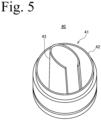
Fig. 5 is a perspective view of a pouring unit constituting the packaging container illustrated inFig 4 . -
Fig. 6A and Fig. 6B are explanatory views for explaining an action of the pouring spout according to the present invention. - An embodiment of the present invention is described below with reference to the drawings. Note that the present invention includes inventions of the same technical idea as the modes set forth in the embodiments and drawings below, and the technical scope of the present invention is not limited to those described in the embodiments and drawings.
- A
pouring spout 10 for a refill container according to the present invention is as specified inclaim 1. - The
pouring spout 10 for a refill container according to the present invention exhibits the particular effect of making it possible to separate theclosing member 20 serving as a component that closes the tubular pouringpart 11 of thepouring spout 10 from the spoutmain body 10A of thepouring spout 10, and communicate achannel 10b formed in the tubular pouringpart 11 of thepouring spout 10, without producing broken pieces or the like. - The following describes an overview of a container provided with the
pouring spout 10, a specific configuration of thepouring spout 10, an overview of apackaging container 30 used after being refilled with contents stored in the container, and the action of thepouring spout 10. Note that, in the present specification, a mode in which thepouring spout 10 comprises the spoutmain body 10A, theclosing member 20, and acoupling member 21 is described. Further, "packaging container" refers to a container refilled with contents, and "container" refers to a container used as a refilling container or the like storing contents for refilling the packaging container with contents and provided with the pouring spout according to the present invention. - The container provided with the
pouring spout 10 according to the present invention is mainly used as a refilling container for refilling thepackaging container 30 used separately from this container with contents. The forms and types of the refilling container are not particularly limited.Fig. 1 shows a standingpouch 1 as an example of a refilling container. This standingpouch 1 comprises a pair offlat surface parts 2 facing each other, abottom surface part 3 that closes a bottom part of the refilling container, and the pouringspout 10 according to the present invention. - The
flat surface parts 2 are sealed together at an upper edge, and sealed together at both side edges. Lower edges of the pair offlat surface parts 2 are each sealed at an edge part of thebottom surface part 3 facing the lower edge of theflat surface part 2. Thebottom surface part 3 is folded in half at acrease 4 at a center thereof, and thecrease 4 is folded toward an upper side of the standingpouch 1. Thebottom surface part 3 is configured to allow a bottom part of the standingpouch 1 to be unfolded by the unfolding of thebottom surface part 3 from the folded state in the directions in which theflat surface parts 2 of the standingpouch 1 are arranged. - The pouring
spout 10 according to the present invention is attached to an upper edge of the standingpouch 1. The pouringspout 10 is configured by the spoutmain body 10A and acap 19 that freely opens and closes the spoutmain body 10A. Note that, in the present embodiment, a case where the pouringspout 10 is attached to a middle of an upper part of the standingpouch 1 is given as an example. However, while not particularly illustrated in the drawings, the pouringspout 10 may be provided in a position shifted to a side part in a width direction in the upper part of the standingpouch 1. Further, the standingpouch 1 may be provided with an area communicated by an inclined part where the upper edge and the side edge are obliquely inclined, and the pouringspout 10 may be attached to the inclined part. - The standing
pouch 1 is used as a refilling container for transferring the contents into the packaging container 30 (refer toFig. 4 ) prepared separately from the standingpouch 1. When the contents are transferred into thepackaging container 30, thecap 19 that closes the pouringspout 10 is removed, and the standingpouch 1 is turned upside down. Then, the pouringspout 10 is inserted into a pouringunit 40 of thepackaging container 30, and the contents are transferred directly from the standingpouch 1 into thepackaging container 30. Note that this action is described in detail later. - The pouring
spout 10, as illustrated inFig. 2 andFig. 3 , comprises thetubular pouring part 11 and the attachedpart 15. Thetubular pouring part 11 forms a cylinder. The attachedpart 15 is an area attached to the standingpouch 1 serving as a container provided with this pouringspout 10, and is provided on the one end A side of thetubular pouring part 11 in the axial direction L. Thetubular pouring part 11 is an area used when the contents of the standingpouch 1 provided with the pouringspout 10 are poured from the standingpouch 1. Thetubular pouring part 11 has a hollow interior, and both ends in the axial direction L are open in a circular shape. That is, thechannel 10b is formed in the interior of thetubular pouring part 11. Thus, thetubular pouring part 11 is configured to allow the inner side and the outer side of the standingpouch 1 to communicate. - A
thread part 12 is formed on an outer circumferential surface of thetubular pouring part 11. Thethread part 12 extends in a circumferential direction, shifts position in the axial direction L, and has a spiral shape. Thisthread part 12 is an area that engages with a thread part (not illustrated) formed on an inner surface of thecap 19. Thetubular pouring part 11 is configured so that, with the thread part of thecap 19 engaged with thethread part 12, the other end B side of thetubular pouring part 11 is closed and opened. - The attached
part 15 has a so-called boat shape. A boat shape refers to a shape in which side surfaceparts 16 of the attachedpart 15 on both sides in a horizontal direction (direction denoted by reference sign Y inFig. 3 ) protrude toward the outer sides, and have acute angles that come to a point on both sides in a vertical direction (direction denoted by reference sign X inFig. 3 ). Heights of theside surface parts 16 are uniformly formed. - Each of the
side surface parts 16 is configured by aninclined surface part 16a that inclines from a center toward the outer side in the Y direction, from both ends in the X direction toward the middle, and acurved part 16b that protrudes toward the outer sides in the Y direction in a center portion in the X direction. Thecurved part 16b, as illustrated inFig. 3 , has an arc shape when the pouringspout 10 is viewed from the one end A side. Further, a plurality of protrudingparts 17 extending in the vertical direction are formed on each of theside surface parts 16, as illustrated inFig. 2 . A hole 10c that passes through thisside surface part 16 in a height direction is formed in a center of the attachedpart 15. This hole 10c partially constitutes thechannel 10b formed in the interior of thetubular pouring part 11. - In this pouring
spout 10, aflange 18 protruding toward the outer side in a radial direction is formed in a boundary portion between the tubular pouringpart 11 and the attachedpart 15. Thisflange 18 is an area extending along the upper edge of the standingpouch 1 when the pouringspout 10 is attached to the upper end of the standingpouch 1. - The closing
member 20 is a component for closing thechannel 10b of the pouringspout 10, and is configured as a separate body from the spoutmain body 10A. This closingmember 20 has a disk shape. The closingmember 20 closes thechannel 10b of the pouringspout 10 by being fit onto the inner side of thechannel 10b of the pouringspout 10 on the one end A side of thetubular pouring part 11 in the axial direction L, that is, on the attachedpart 15 side. On the other hand, the closingmember 20 that closes thechannel 10b of the pouringspout 10 is configured so that the closingmember 20 is removed by an external force applied from the other end B side opposite to the one end A side of thetubular pouring part 11 in the axial direction L from the inner circumferential surface of thetubular pouring part 11. Thus, a diameter of the closingmember 20 is formed to the same size as or slightly smaller than an inner diameter of thechannel 10b of the pouringspout 10. - Note that the
channel 10b of the pouringspout 10 of the present embodiment has a circular cross-sectional shape, and thus the closingmember 20 fitted into thechannel 10b also has a circular outer shape. However, the outer shape of the closingmember 20 is formed into a shape corresponding to the cross-sectional shape of thechannel 10b of the pouringspout 10. For example, when thechannel 10b of the pouringspout 10 has an elliptical cross-sectional shape, the outer shape of the closingmember 20 is formed into an elliptical shape corresponding to the cross-sectional shape of thechannel 10b of the pouringspout 10. With the outer shape of the closingmember 20 formed into a shape corresponding to the cross-sectional shape of thechannel 10b of the pouringspout 10, the closingmember 20 closes thechannel 10b without forming a gap between the closingmember 20 and the inner circumferential surface of thechannel 10b of the pouringspout 10 when the closingmember 20 is fit onto the inner side of thechannel 10b of the pouringspout 10. - The closing
member 20 is connected to the spoutmain body 10A by thecoupling member 21. Thecoupling member 21 is made of a resin, and has a long, narrow string shape. Alternatively, thiscoupling member 21 can be formed into a strip shape as well. That is, the closingmember 20 is connected by thecoupling member 21 having a string shape or a strip shape to the spoutmain body 10A. One end of thecoupling member 21 in the longitudinal direction is coupled to an end surface of the spoutmain body 10A on the one end A side. Specifically, one end of thecoupling member 21 in the longitudinal direction is coupled to a lower end surface of the attachedpart 15. This one end is coupled to the lower end surface of the attachedpart 15 at a position slightly shifted to the outer side in a radial direction from the peripheral part of thechannel 10b. In contrast, the other end of thecoupling member 21 in the longitudinal direction is coupled to alower surface 20b of the closingmember 20. That is, thecoupling member 21 couples thelower surface 20b of the closingmember 20, which is a surface facing the lower side in a mode of being fitted into thechannel 10b, and the attachedpart 15. - Note that an
upper surface 20a of the closingmember 20 is a surface facing the upper side in a mode in which the closingmember 20 is fitted into thechannel 10b of the pouringspout 10. That is, theupper surface 20a of the closingmember 20 is a surface facing the other end B side of thetubular pouring part 11 in the axial direction L in a mode in which the closingmember 20 is fitted into thechannel 10b of the pouringspout 10. In contrast, thelower surface 20b of the closingmember 20 is a surface facing the lower side in a mode in which the closingmember 20 is fitted into thechannel 10b of the pouringspout 10. That is, the lower surface of the closingmember 20 is a surface facing the interior of the container (standing pouch 1) to which the pouringspout 10 is attached in a mode in which the closingmember 20 is fitted into thechannel 10b of the pouringspout 10. Thecoupling member 21 couples the closingmember 20 and the spoutmain body 10A in such a manner that a force is applied in a direction in which the closingmember 20 is separated from thechannel 10b of the pouringspout 10. - Both ends of the
coupling member 21 couple the spoutmain body 10A and the closingmember 20 as described above, and thus the closingmember 20 is fitted onto the inner side of thechannel 10b without thecoupling member 21 getting pinched between the closingmember 20 and thechannel 10b. Further, when the closingmember 20 is removed from the inner side of thechannel 10b, the closingmember 20 is maintained in a state of connection to the pouringspout 10 without being separated from the spoutmain body 10A. Thecoupling member 21 couples the closingmember 20 and the spoutmain body 10A in such a manner that a force is applied in a direction in which the closingmember 20 is separated from thechannel 10b of the pouringspout 10, and thus the closingmember 20 removed from thechannel 10b is kept from blocking thechannel 10b once again. As a result, it is possible to smoothly transfer contents from the standingpouch 1 into thepackaging container 30. - The pouring
spout 10 described above is molded using a resin such as polyethylene, polypropylene, polyester, ethylene-vinyl copolymer, and polyvinyl chloride. However, the material of the pouringspout 10 is not limited as long as the pouring spout is moldable. Further, examples of applicable raw materials of the resin include petroleum-derived materials, plant-derived materials, copolymers thereof, and blend resins thereof. - The
packaging container 30 is a container used after being refilled with contents stored in the standingpouch 1. Thepackaging container 30 is made of a resin or the like, for example.Fig. 4 shows an example of thepackaging container 30. Thepackaging container 30 illustrated inFig. 4 is configured by a containermain body 31 provided with ahandle 32, and the pouringunit 40 for pouring the contents stored in the containermain body 31. Thispackaging container 30 is used by removing from thepackaging container 30 the contents moved from the standingpouch 1 in an amount required when necessary. - The pouring
unit 40 of thepackaging container 30 is configured by amain body part 41, and acap 49 for opening and closing themain body part 41. Themain body part 41, as illustrated inFig. 5 , comprises aperipheral wall surface 42, and anozzle 43 disposed on an inner side of thisperipheral wall surface 42. Theperipheral wall surface 42 has a cylinder shape. The inner side of theperipheral wall surface 42 is hollow. - The
nozzle 43 is disposed in a middle or substantial middle position of themain body part 41. Thenozzle 43 is connected to theperipheral wall surface 42, and is integrated with theperipheral wall surface 42. Thenozzle 43 is configured to protrude toward an upper side of themain body part 41, with a tip end thereof positioned on an upper side of the upper end of theperipheral wall surface 42.Fig. 5 shows one example of the shape of thenozzle 43, and the shape of thenozzle 43 is not particularly limited. - The pouring
spout 10 can be manufactured by various manufacturing methods. However, when manufacturing efficiency, manufacturing cost, and quality are considered, the spoutmain body 10A, the closingmember 20, and thecoupling member 21 are preferably integrally molded by injection-molding a resin. The manufacturing method for injection-molding a resin allows the spoutmain body 10A, the closingmember 20, and thecoupling member 21 to be integrally molded using the same material, making it possible to increase the manufacturing efficiency and keep the manufacturing cost to a low level. Further, once a die is manufactured, products having the identical quality can be repeatedly manufactured. - The procedure for refilling the
packaging container 30 with the contents stored in the standingpouch 1, and the action of the pouringspout 10 of the present embodiment will now be described with reference toFig. 6 . Note that, to make the action of the pouringspout 10 easy to understand, the standingpouch 1 and the containermain body 31 of thepackaging container 30 are not illustrated inFig. 6 . However, the pouringspout 10 is attached to the standingpouch 1, which is a refilling container, illustrated inFig. 1 , and the pouringunit 40 is provided to thepackaging container 30 illustrated inFig. 4 . - First, the
cap 19 is removed from the pouringspout 10, the standingpouch 1 is turned upside down, and the pouringspout 10 is positioned on a lower side of the standingpouch 1. Thechannel 10b of the pouringspout 10 is closed by the closingmember 20, and thus the contents stored in the standingpouch 1 never spill out. Next, as illustrated inFig. 6A , the pouringspout 10 is matched with the position of the pouringunit 40 of thepackaging container 30 from which thecap 19 is removed, and thenozzle 43 of the pouringunit 40 is inserted into thechannel 10b of the pouringspout 10. That is, thenozzle 43 of the pouringunit 40 is inserted into thechannel 10b configured on the inner side of thetubular pouring part 11 constituting the pouringspout 10. - Next, with the
nozzle 43 inserted into thetubular pouring part 11, the pouringspout 10 is pressed further downward on the pouringunit 40 side. When the pouringspout 10 is pressed downward, the tip end of thenozzle 43 presses the closingmember 20 upward. Thus, as illustrated inFig. 6B , the closingmember 20 is removed from thechannel 10b constituting the inner side of thetubular pouring part 11. That is, the closingmember 20 is removed by an external force applied from the other end B side (tip end side of the cylindrical pouring part) opposite to the one end A side (end part side provided with the attached part 15) of the tubular pouring part in the axial direction L from the inner circumferential surface of thetubular pouring part 11. The closingmember 20, in a mode of removal from the inner circumferential surface, is fitted horizontally onto an inner circumferential surface of thetubular pouring part 11 on the one end A side thereof. At this time, the closingmember 20 is configured as a separate body from the spoutmain body 10A, and is fitted into thechannel 10b constituting thetubular pouring part 11, simply closing thechannel 10b, and thus is smoothly removed from thechannel 10b without causing the closingmember 20 itself to be damage by thenozzle 43. As a result, simply the contents are moved into thepackaging container 30 without producing broken pieces. - Further, as illustrated in
Fig. 6B , thenozzle 43 is inserted into the interior of thetubular pouring part 11 and, when the closingmember 20 is removed from the spoutmain body 10A, atip end part 11a of thetubular pouring part 11 comes into contact with an outer circumferential surface of the nozzle. That is, in a mode in which thenozzle 43 is inserted into thetubular pouring part 11, the tip end of thetubular pouring part 11 is formed to a size resulting in contact with the outer circumferential surface of a base portion of thenozzle 43. Thus, the contents poured from the refill container 1 (standing pouch) are moved to thepackaging container 30 through thenozzle 43 without leaking to the outer side of thenozzle 43. - With regard to this point, in conventional products, the component for closing the channel and a pouring spout were integrally configured. When a component for closing was to be opened, a portion having a thin thickness was formed around the component for closing, and then the portion having a thin thickness was cut when the
nozzle 43 pressed the component for closing upward. However, according to the configuration of the related art, even when the component for closing was pressed upward by thenozzle 43, the portion formed with a thin thickness might not be fully cut, making formation of the channel incomplete. Further, when the component for closing was fully cut from the thinned portion by thenozzle 43, a defect might occur in which the component for closing was moved along with the contents to thepackaging container 30. - According to the pouring
spout 10 of the present embodiment as described above, when the pouringspout 10 is attached to the standingpouch 1 serving as a refilling container, thechannel 10b formed in the interior of thetubular pouring part 11 constituting the pouringspout 10 is closed, making it possible to prevent the contents from coming into contact with outside air. Further, it is possible to separate the component that closes thetubular pouring part 11 of the pouringspout 10 from the pouringspout 10 and communicate thechannel 10b formed in thetubular pouring part 11 of the pouringspout 10 without producing broken pieces or the like. -
- 1
- Refill container (Standing pouch)
- 2
- Flat surface part
- 3
- Bottom surface part
- 4
- Crease
- 10
- Pouring spout
- 10A
- Spout main body
- 10b
- Channel
- 10c
- Hole
- 11
- Tubular pouring part
- 11a
- Tip end part
- 12
- Thread part
- 15
- Attached part
- 16
- Side surface part
- 16a
- Inclined surface part
- 16b
- Curved part
- 17
- Protruding part
- 18
- Flange
- 19
- Cap
- 20
- Closing member
- 20a
- Upper surface
- 20b
- Lower surface
- 21
- Coupling member
- 30
- Packaging container
- 31
- Container main body
- 32
- Handle
- 40
- Pouring unit
- 41
- Main body part
- 42
- Peripheral wall surface
- 43
- Nozzle
- A
- One end in axial direction
- B
- Other end in axial direction
- L
- Extending direction of tubular pouring part
Claims (3)
- A pouring spout (10) for a refill container (1) in which contents for refilling the contents of a packaging container (30) are stored, the pouring spout (10) comprising:a tubular pouring part (11);an attached part (15) attachable to the refill container (1) on one end side of the tubular pouring part (11) in an axial direction; anda closing member (20) for closing the one end side of the tubular pouring part (11), configured as a separate body from a spout main body (10A) of the pouring spout (10), and fitted onto an inner circumferential surface of the tubular pouring part (11) on the one end side thereof in such a manner that the closing member (20) is removed by an external force applied from the other end side opposite to the one end side in the axial direction from the inner circumferential surface of the tubular pouring part (11);characterised in that:the closing member (20) is connected by a coupling member (21) to the spout main body (10A);the coupling member (21) is made of a resin and has a string shape or a strip shape, wherein one end of the coupling member (21) in the longitudinal direction is coupled to a lower end surface of the attached part (15) of the spout main body (10A) at a position slightly shifted to the outer side in a radial direction from a peripheral part of a channel (10b) of the pouring spout (10);the other end of the coupling member (21) in the longitudinal direction is coupled to a lower surface (20b) of the closing member (20), which is a surface of the closing member (20) that is arranged to face an interior of the refill container (1) when the pouring spout (10) is attached to the refill container (1) in a mode in which the closing member (20) is fitted into the channel (10b) of the pouring spout (10);the coupling member (21) couples the closing member (20) and the attached part (15) of the spout main body (10A) in such a manner that a force is applied in a direction in which the closing member (20) is separated from the channel (10b) of the pouring spout (10).
- The pouring spout (10) according to claim 1, wherein
the closing member (20), the coupling member (21), and the spout main body (10A) are configured as an integrated object made of a same material. - The pouring spout (10) according to claim 1, wherein
the closing member (20) is fitted horizontally onto the inner circumferential surface of the tubular pouring part (11) on the one end side thereof.
Applications Claiming Priority (2)
| Application Number | Priority Date | Filing Date | Title |
|---|---|---|---|
| JP2016238187A JP6960731B2 (en) | 2016-12-08 | 2016-12-08 | Container pouring spout |
| PCT/JP2017/043944 WO2018105686A1 (en) | 2016-12-08 | 2017-12-07 | Container pouring spout |
Publications (3)
| Publication Number | Publication Date |
|---|---|
| EP3543162A1 EP3543162A1 (en) | 2019-09-25 |
| EP3543162A4 EP3543162A4 (en) | 2019-12-11 |
| EP3543162B1 true EP3543162B1 (en) | 2025-07-09 |
Family
ID=62492003
Family Applications (1)
| Application Number | Title | Priority Date | Filing Date |
|---|---|---|---|
| EP17877634.0A Active EP3543162B1 (en) | 2016-12-08 | 2017-12-07 | A pouring spout for a refill container |
Country Status (8)
| Country | Link |
|---|---|
| US (1) | US10961025B2 (en) |
| EP (1) | EP3543162B1 (en) |
| JP (1) | JP6960731B2 (en) |
| KR (1) | KR20190094162A (en) |
| CN (1) | CN110062737B (en) |
| MY (1) | MY200018A (en) |
| PH (1) | PH12019501240A1 (en) |
| WO (1) | WO2018105686A1 (en) |
Families Citing this family (4)
| Publication number | Priority date | Publication date | Assignee | Title |
|---|---|---|---|---|
| JP7174593B2 (en) | 2018-10-30 | 2022-11-17 | 藤森工業株式会社 | Method for refilling contents from spout and refilling container to packaging container |
| JP7193305B2 (en) * | 2018-10-30 | 2022-12-20 | 藤森工業株式会社 | pouring spout |
| JP7251964B2 (en) * | 2018-12-19 | 2023-04-04 | 藤森工業株式会社 | Packaging bag with spout, and manufacturing method thereof |
| JP7251965B2 (en) * | 2018-12-19 | 2023-04-04 | 藤森工業株式会社 | Packaging bag with spout, and manufacturing method thereof |
Family Cites Families (37)
| Publication number | Priority date | Publication date | Assignee | Title |
|---|---|---|---|---|
| US1241352A (en) * | 1915-02-23 | 1917-09-25 | Charles Doering Jr | Water-dispensing device. |
| US3347410A (en) * | 1966-08-31 | 1967-10-17 | Schwartzman Gilbert | Mixing assemblies for applicators |
| IT994127B (en) * | 1973-08-03 | 1975-10-20 | Sigma Tau Ind Farmaceuti | DEVICE FOR THE HERMETIC CLOSING OF CONTAINERS EQUIPPED WITH PERFORATOR AND GOCCIMETER |
| US4195730A (en) * | 1978-06-20 | 1980-04-01 | General Foods Corporation | Container having separate storage facilities for two materials |
| US4375864A (en) * | 1980-07-21 | 1983-03-08 | Scholle Corporation | Container for holding and dispensing fluid |
| US4371015A (en) * | 1980-12-24 | 1983-02-01 | Tbs, Inc. | Toner loading system having cartridge with displaceable diaphragm |
| US4445551A (en) * | 1981-11-09 | 1984-05-01 | Bond Curtis J | Quick-disconnect coupling and valve assembly |
| US4614437A (en) * | 1984-11-02 | 1986-09-30 | Dougherty Brothers Company | Mixing container and adapter |
| US5041267A (en) * | 1986-12-30 | 1991-08-20 | Air Products And Chemicals, Inc. | Ultra high purity reagent container with large breakseal |
| US5533553A (en) * | 1994-01-26 | 1996-07-09 | Colgate-Palmolive Co. | Container set comprising at least two containers |
| US5735320A (en) * | 1996-08-21 | 1998-04-07 | The Sherwin-Williams Company | Dispenser for a two-part composition |
| NL1006636C2 (en) * | 1997-07-21 | 1999-01-25 | Itsac Nv | Connection assembly for a fluid connection. |
| NL1011960C2 (en) * | 1999-05-04 | 2000-11-07 | Itsac Nv | Container, in particular a flexible container, with a closable opening and method for filling such a container. |
| NL1016292C2 (en) * | 2000-09-28 | 2002-04-02 | Itsac Nv | Bag as well as a delivery system comprising such a bag and methods for manufacturing and filling such a bag. |
| JP2003165560A (en) | 2001-11-30 | 2003-06-10 | Yoshino Kogyosho Co Ltd | Openable and closable valve body for dispensing container |
| EP1676784A1 (en) * | 2004-12-29 | 2006-07-05 | The Procter & Gamble Company | Flexible container containing a liquid product, and a process for making a liquid-filled, flexible container |
| US7635012B2 (en) * | 2006-06-12 | 2009-12-22 | Jpro Dairy International, Inc. | Sealed storage container with a coupling assembly |
| DE102008012973B3 (en) * | 2008-03-06 | 2009-04-02 | Henkel Ag & Co. Kgaa | System for refilling flowable or pourable detergents or cleaners |
| CN101570257B (en) * | 2008-04-17 | 2014-09-17 | 杨泰和 | The pressure-opening storage device with the lid lifted and pre-forced |
| US8590700B2 (en) * | 2008-04-17 | 2013-11-26 | Tai-Her Yang | Sleeved to press-open type storage device with a prestressed to open closure |
| JP5207312B2 (en) * | 2009-04-30 | 2013-06-12 | 株式会社吉野工業所 | Refill container |
| JP5424148B2 (en) * | 2009-06-30 | 2014-02-26 | 株式会社吉野工業所 | Combination of continuous use container and refill container |
| US8910673B2 (en) * | 2009-12-25 | 2014-12-16 | Yoshino Kogyosho Co., Ltd. | Synthetic resin bottle, and a combination of regularly used container and refill container |
| JP5357099B2 (en) * | 2010-03-31 | 2013-12-04 | 株式会社吉野工業所 | Pouring tap and container equipped with it |
| JP5523899B2 (en) * | 2010-03-31 | 2014-06-18 | 株式会社吉野工業所 | Refill nozzle |
| EP2660165B1 (en) * | 2010-12-27 | 2017-08-09 | Kao Corporation | Package |
| JP5744681B2 (en) * | 2011-08-30 | 2015-07-08 | 株式会社吉野工業所 | Pouring cap |
| WO2013099978A1 (en) * | 2011-12-28 | 2013-07-04 | 花王株式会社 | Plug member for refill container |
| JP5944662B2 (en) * | 2011-12-28 | 2016-07-05 | 花王株式会社 | Refilling extraction cap |
| JP2013203464A (en) | 2012-03-29 | 2013-10-07 | Toppan Printing Co Ltd | Refill container |
| JP6183847B2 (en) | 2012-11-30 | 2017-08-23 | 花王株式会社 | Refill container stopper |
| CN104837735B (en) * | 2012-11-30 | 2017-01-18 | 花王株式会社 | Refilling container stopper |
| WO2014103574A1 (en) * | 2012-12-28 | 2014-07-03 | 株式会社コーセー | Pouring structure for refill container |
| US10138448B2 (en) * | 2016-04-11 | 2018-11-27 | Veltek Associates, Inc | Deactivation wipe kit |
| JP6236139B1 (en) * | 2016-12-08 | 2017-11-22 | 藤森工業株式会社 | Connection structure with spout for refilling containers and dispensing unit for packaging containers |
| JP6194132B1 (en) * | 2017-03-21 | 2017-09-06 | 藤森工業株式会社 | Container spout |
| US10661968B1 (en) * | 2019-06-20 | 2020-05-26 | Elc Management Llc | Container system for mixing and dispensing |
-
2016
- 2016-12-08 JP JP2016238187A patent/JP6960731B2/en active Active
-
2017
- 2017-12-07 KR KR1020197016142A patent/KR20190094162A/en not_active Ceased
- 2017-12-07 MY MYPI2019003173A patent/MY200018A/en unknown
- 2017-12-07 CN CN201780074791.4A patent/CN110062737B/en active Active
- 2017-12-07 US US16/466,933 patent/US10961025B2/en active Active
- 2017-12-07 EP EP17877634.0A patent/EP3543162B1/en active Active
- 2017-12-07 WO PCT/JP2017/043944 patent/WO2018105686A1/en not_active Ceased
-
2019
- 2019-06-04 PH PH12019501240A patent/PH12019501240A1/en unknown
Also Published As
| Publication number | Publication date |
|---|---|
| CN110062737B (en) | 2022-04-12 |
| US10961025B2 (en) | 2021-03-30 |
| CN110062737A (en) | 2019-07-26 |
| EP3543162A1 (en) | 2019-09-25 |
| MY200018A (en) | 2023-12-04 |
| KR20190094162A (en) | 2019-08-12 |
| PH12019501240A1 (en) | 2020-03-02 |
| WO2018105686A1 (en) | 2018-06-14 |
| JP6960731B2 (en) | 2021-11-05 |
| JP2018095258A (en) | 2018-06-21 |
| US20200062463A1 (en) | 2020-02-27 |
| EP3543162A4 (en) | 2019-12-11 |
Similar Documents
| Publication | Publication Date | Title |
|---|---|---|
| EP3543165B1 (en) | Connection structure between refill container pouring spout and package container pouring unit | |
| US11203468B2 (en) | Pouring spout of container | |
| EP1441960B1 (en) | Liquid dispensing closure | |
| US9523596B2 (en) | Auto-refill single dose dispenser | |
| US10961025B2 (en) | Pouring spout of container | |
| KR20040056373A (en) | Closing element with outlet channel extending in funnel-like manner and film bag | |
| CN101646606A (en) | Unitary dispensing assembly | |
| US6116440A (en) | Resealable thermoformed container | |
| US20200339312A1 (en) | Plastic closure part with severable membrane | |
| JP5365283B2 (en) | Refill container | |
| RU2415789C2 (en) | Container and method of its fabrication | |
| JP6783114B2 (en) | Note cap | |
| JP5121144B2 (en) | Pouch plug, pouch with plug, and package | |
| EP3875390B1 (en) | Pouring spout | |
| JP4253728B2 (en) | Hinge cap and manufacturing method thereof | |
| JP7703389B2 (en) | Hinge Cap | |
| JPH0333628Y2 (en) | ||
| RU2839488C2 (en) | Cover for container | |
| JP2004284647A (en) | Container spout | |
| CN106458388A (en) | Cap with a disposable cover | |
| JP2023016766A (en) | Spout plug manufacturing method, spout plug, and packaging container | |
| JPH10120007A (en) | Nozzle for pouring and bag using the same | |
| JP2020196470A (en) | Pour-out cap | |
| JP2004083071A (en) | One-piece spout and its injection mold | |
| JP2005239167A (en) | Pouring tap with cap |
Legal Events
| Date | Code | Title | Description |
|---|---|---|---|
| STAA | Information on the status of an ep patent application or granted ep patent |
Free format text: STATUS: THE INTERNATIONAL PUBLICATION HAS BEEN MADE |
|
| PUAI | Public reference made under article 153(3) epc to a published international application that has entered the european phase |
Free format text: ORIGINAL CODE: 0009012 |
|
| STAA | Information on the status of an ep patent application or granted ep patent |
Free format text: STATUS: REQUEST FOR EXAMINATION WAS MADE |
|
| 17P | Request for examination filed |
Effective date: 20190618 |
|
| AK | Designated contracting states |
Kind code of ref document: A1 Designated state(s): AL AT BE BG CH CY CZ DE DK EE ES FI FR GB GR HR HU IE IS IT LI LT LU LV MC MK MT NL NO PL PT RO RS SE SI SK SM TR |
|
| AX | Request for extension of the european patent |
Extension state: BA ME |
|
| A4 | Supplementary search report drawn up and despatched |
Effective date: 20191113 |
|
| RIC1 | Information provided on ipc code assigned before grant |
Ipc: B65D 75/58 20060101ALI20191107BHEP Ipc: B65D 33/38 20060101AFI20191107BHEP Ipc: B65D 47/06 20060101ALI20191107BHEP |
|
| DAV | Request for validation of the european patent (deleted) | ||
| DAX | Request for extension of the european patent (deleted) | ||
| STAA | Information on the status of an ep patent application or granted ep patent |
Free format text: STATUS: EXAMINATION IS IN PROGRESS |
|
| 17Q | First examination report despatched |
Effective date: 20200909 |
|
| RAP3 | Party data changed (applicant data changed or rights of an application transferred) |
Owner name: ZACROS CORPORATION |
|
| GRAP | Despatch of communication of intention to grant a patent |
Free format text: ORIGINAL CODE: EPIDOSNIGR1 |
|
| STAA | Information on the status of an ep patent application or granted ep patent |
Free format text: STATUS: GRANT OF PATENT IS INTENDED |
|
| INTG | Intention to grant announced |
Effective date: 20250317 |
|
| GRAS | Grant fee paid |
Free format text: ORIGINAL CODE: EPIDOSNIGR3 |
|
| GRAA | (expected) grant |
Free format text: ORIGINAL CODE: 0009210 |
|
| STAA | Information on the status of an ep patent application or granted ep patent |
Free format text: STATUS: THE PATENT HAS BEEN GRANTED |
|
| AK | Designated contracting states |
Kind code of ref document: B1 Designated state(s): AL AT BE BG CH CY CZ DE DK EE ES FI FR GB GR HR HU IE IS IT LI LT LU LV MC MK MT NL NO PL PT RO RS SE SI SK SM TR |
|
| REG | Reference to a national code |
Ref country code: GB Ref legal event code: FG4D |
|
| REG | Reference to a national code |
Ref country code: CH Ref legal event code: EP |
|
| REG | Reference to a national code |
Ref country code: IE Ref legal event code: FG4D |
|
| REG | Reference to a national code |
Ref country code: DE Ref legal event code: R096 Ref document number: 602017090511 Country of ref document: DE |
|
| PG25 | Lapsed in a contracting state [announced via postgrant information from national office to epo] |
Ref country code: PT Free format text: LAPSE BECAUSE OF FAILURE TO SUBMIT A TRANSLATION OF THE DESCRIPTION OR TO PAY THE FEE WITHIN THE PRESCRIBED TIME-LIMIT Effective date: 20251110 |
|
| PG25 | Lapsed in a contracting state [announced via postgrant information from national office to epo] |
Ref country code: NL Free format text: LAPSE BECAUSE OF FAILURE TO SUBMIT A TRANSLATION OF THE DESCRIPTION OR TO PAY THE FEE WITHIN THE PRESCRIBED TIME-LIMIT Effective date: 20250709 |
|
| REG | Reference to a national code |
Ref country code: AT Ref legal event code: MK05 Ref document number: 1811681 Country of ref document: AT Kind code of ref document: T Effective date: 20250709 |
|
| PG25 | Lapsed in a contracting state [announced via postgrant information from national office to epo] |
Ref country code: IS Free format text: LAPSE BECAUSE OF FAILURE TO SUBMIT A TRANSLATION OF THE DESCRIPTION OR TO PAY THE FEE WITHIN THE PRESCRIBED TIME-LIMIT Effective date: 20251109 |
|
| PGFP | Annual fee paid to national office [announced via postgrant information from national office to epo] |
Ref country code: DE Payment date: 20251211 Year of fee payment: 9 |
|
| PGFP | Annual fee paid to national office [announced via postgrant information from national office to epo] |
Ref country code: GB Payment date: 20251219 Year of fee payment: 9 |
|
| PG25 | Lapsed in a contracting state [announced via postgrant information from national office to epo] |
Ref country code: NO Free format text: LAPSE BECAUSE OF FAILURE TO SUBMIT A TRANSLATION OF THE DESCRIPTION OR TO PAY THE FEE WITHIN THE PRESCRIBED TIME-LIMIT Effective date: 20251009 |
|
| REG | Reference to a national code |
Ref country code: LT Ref legal event code: MG9D |
|
| PG25 | Lapsed in a contracting state [announced via postgrant information from national office to epo] |
Ref country code: AT Free format text: LAPSE BECAUSE OF FAILURE TO SUBMIT A TRANSLATION OF THE DESCRIPTION OR TO PAY THE FEE WITHIN THE PRESCRIBED TIME-LIMIT Effective date: 20250709 |
|
| PG25 | Lapsed in a contracting state [announced via postgrant information from national office to epo] |
Ref country code: FI Free format text: LAPSE BECAUSE OF FAILURE TO SUBMIT A TRANSLATION OF THE DESCRIPTION OR TO PAY THE FEE WITHIN THE PRESCRIBED TIME-LIMIT Effective date: 20250709 |
|
| PGFP | Annual fee paid to national office [announced via postgrant information from national office to epo] |
Ref country code: IT Payment date: 20251223 Year of fee payment: 9 |
|
| PG25 | Lapsed in a contracting state [announced via postgrant information from national office to epo] |
Ref country code: HR Free format text: LAPSE BECAUSE OF FAILURE TO SUBMIT A TRANSLATION OF THE DESCRIPTION OR TO PAY THE FEE WITHIN THE PRESCRIBED TIME-LIMIT Effective date: 20250709 |
|
| PGFP | Annual fee paid to national office [announced via postgrant information from national office to epo] |
Ref country code: FR Payment date: 20251229 Year of fee payment: 9 |
|
| PG25 | Lapsed in a contracting state [announced via postgrant information from national office to epo] |
Ref country code: GR Free format text: LAPSE BECAUSE OF FAILURE TO SUBMIT A TRANSLATION OF THE DESCRIPTION OR TO PAY THE FEE WITHIN THE PRESCRIBED TIME-LIMIT Effective date: 20251010 |
|
| PG25 | Lapsed in a contracting state [announced via postgrant information from national office to epo] |
Ref country code: SE Free format text: LAPSE BECAUSE OF FAILURE TO SUBMIT A TRANSLATION OF THE DESCRIPTION OR TO PAY THE FEE WITHIN THE PRESCRIBED TIME-LIMIT Effective date: 20250709 |
|
| PG25 | Lapsed in a contracting state [announced via postgrant information from national office to epo] |
Ref country code: LV Free format text: LAPSE BECAUSE OF FAILURE TO SUBMIT A TRANSLATION OF THE DESCRIPTION OR TO PAY THE FEE WITHIN THE PRESCRIBED TIME-LIMIT Effective date: 20250709 |
|
| PG25 | Lapsed in a contracting state [announced via postgrant information from national office to epo] |
Ref country code: PL Free format text: LAPSE BECAUSE OF FAILURE TO SUBMIT A TRANSLATION OF THE DESCRIPTION OR TO PAY THE FEE WITHIN THE PRESCRIBED TIME-LIMIT Effective date: 20250709 Ref country code: BG Free format text: LAPSE BECAUSE OF FAILURE TO SUBMIT A TRANSLATION OF THE DESCRIPTION OR TO PAY THE FEE WITHIN THE PRESCRIBED TIME-LIMIT Effective date: 20250709 |
|
| PG25 | Lapsed in a contracting state [announced via postgrant information from national office to epo] |
Ref country code: RS Free format text: LAPSE BECAUSE OF FAILURE TO SUBMIT A TRANSLATION OF THE DESCRIPTION OR TO PAY THE FEE WITHIN THE PRESCRIBED TIME-LIMIT Effective date: 20251009 |
|
| PG25 | Lapsed in a contracting state [announced via postgrant information from national office to epo] |
Ref country code: ES Free format text: LAPSE BECAUSE OF FAILURE TO SUBMIT A TRANSLATION OF THE DESCRIPTION OR TO PAY THE FEE WITHIN THE PRESCRIBED TIME-LIMIT Effective date: 20250709 |
|
| PG25 | Lapsed in a contracting state [announced via postgrant information from national office to epo] |
Ref country code: RO Free format text: LAPSE BECAUSE OF FAILURE TO SUBMIT A TRANSLATION OF THE DESCRIPTION OR TO PAY THE FEE WITHIN THE PRESCRIBED TIME-LIMIT Effective date: 20250709 |
|
| PG25 | Lapsed in a contracting state [announced via postgrant information from national office to epo] |
Ref country code: SM Free format text: LAPSE BECAUSE OF FAILURE TO SUBMIT A TRANSLATION OF THE DESCRIPTION OR TO PAY THE FEE WITHIN THE PRESCRIBED TIME-LIMIT Effective date: 20250709 |
|
| REG | Reference to a national code |
Ref country code: DE Ref legal event code: R097 Ref document number: 602017090511 Country of ref document: DE |
|
| PG25 | Lapsed in a contracting state [announced via postgrant information from national office to epo] |
Ref country code: DK Free format text: LAPSE BECAUSE OF FAILURE TO SUBMIT A TRANSLATION OF THE DESCRIPTION OR TO PAY THE FEE WITHIN THE PRESCRIBED TIME-LIMIT Effective date: 20250709 |
|
| PG25 | Lapsed in a contracting state [announced via postgrant information from national office to epo] |
Ref country code: CZ Free format text: LAPSE BECAUSE OF FAILURE TO SUBMIT A TRANSLATION OF THE DESCRIPTION OR TO PAY THE FEE WITHIN THE PRESCRIBED TIME-LIMIT Effective date: 20250709 |
|
| PG25 | Lapsed in a contracting state [announced via postgrant information from national office to epo] |
Ref country code: EE Free format text: LAPSE BECAUSE OF FAILURE TO SUBMIT A TRANSLATION OF THE DESCRIPTION OR TO PAY THE FEE WITHIN THE PRESCRIBED TIME-LIMIT Effective date: 20250709 Ref country code: SK Free format text: LAPSE BECAUSE OF FAILURE TO SUBMIT A TRANSLATION OF THE DESCRIPTION OR TO PAY THE FEE WITHIN THE PRESCRIBED TIME-LIMIT Effective date: 20250709 |
|
| PLBE | No opposition filed within time limit |
Free format text: ORIGINAL CODE: 0009261 |
|
| STAA | Information on the status of an ep patent application or granted ep patent |
Free format text: STATUS: NO OPPOSITION FILED WITHIN TIME LIMIT |
|
| REG | Reference to a national code |
Ref country code: CH Ref legal event code: L10 Free format text: ST27 STATUS EVENT CODE: U-0-0-L10-L00 (AS PROVIDED BY THE NATIONAL OFFICE) Effective date: 20260521 |
|
| 26N | No opposition filed |
Effective date: 20260410 |
|
| PG25 | Lapsed in a contracting state [announced via postgrant information from national office to epo] |
Ref country code: LT Free format text: LAPSE BECAUSE OF FAILURE TO SUBMIT A TRANSLATION OF THE DESCRIPTION OR TO PAY THE FEE WITHIN THE PRESCRIBED TIME-LIMIT Effective date: 20250709 |
|
| PG25 | Lapsed in a contracting state [announced via postgrant information from national office to epo] |
Ref country code: MC Free format text: LAPSE BECAUSE OF FAILURE TO SUBMIT A TRANSLATION OF THE DESCRIPTION OR TO PAY THE FEE WITHIN THE PRESCRIBED TIME-LIMIT Effective date: 20250709 |
|
| REG | Reference to a national code |
Ref country code: CH Ref legal event code: H13 Free format text: ST27 STATUS EVENT CODE: U-0-0-H10-H13 (AS PROVIDED BY THE NATIONAL OFFICE) Effective date: 20260723 |