EP3543091A1 - Vehicle-body side face structure - Google Patents
Vehicle-body side face structure Download PDFInfo
- Publication number
- EP3543091A1 EP3543091A1 EP19163410.4A EP19163410A EP3543091A1 EP 3543091 A1 EP3543091 A1 EP 3543091A1 EP 19163410 A EP19163410 A EP 19163410A EP 3543091 A1 EP3543091 A1 EP 3543091A1
- Authority
- EP
- European Patent Office
- Prior art keywords
- vehicle
- face
- width direction
- vehicle width
- garnish
- Prior art date
- Legal status (The legal status is an assumption and is not a legal conclusion. Google has not performed a legal analysis and makes no representation as to the accuracy of the status listed.)
- Withdrawn
Links
- 235000021189 garnishes Nutrition 0.000 claims abstract description 53
- 230000000694 effects Effects 0.000 description 3
- 239000000446 fuel Substances 0.000 description 2
- 230000003014 reinforcing effect Effects 0.000 description 2
- 239000004743 Polypropylene Substances 0.000 description 1
- 239000003054 catalyst Substances 0.000 description 1
- 230000001419 dependent effect Effects 0.000 description 1
- -1 polypropylene Polymers 0.000 description 1
- 229920001155 polypropylene Polymers 0.000 description 1
- 239000000725 suspension Substances 0.000 description 1
- 229920003002 synthetic resin Polymers 0.000 description 1
- 239000000057 synthetic resin Substances 0.000 description 1
Images




Classifications
-
- B—PERFORMING OPERATIONS; TRANSPORTING
- B62—LAND VEHICLES FOR TRAVELLING OTHERWISE THAN ON RAILS
- B62D—MOTOR VEHICLES; TRAILERS
- B62D35/00—Vehicle bodies characterised by streamlining
-
- B—PERFORMING OPERATIONS; TRANSPORTING
- B62—LAND VEHICLES FOR TRAVELLING OTHERWISE THAN ON RAILS
- B62D—MOTOR VEHICLES; TRAILERS
- B62D35/00—Vehicle bodies characterised by streamlining
- B62D35/008—Side spoilers
-
- B—PERFORMING OPERATIONS; TRANSPORTING
- B62—LAND VEHICLES FOR TRAVELLING OTHERWISE THAN ON RAILS
- B62D—MOTOR VEHICLES; TRAILERS
- B62D35/00—Vehicle bodies characterised by streamlining
- B62D35/02—Streamlining the undersurfaces
-
- B—PERFORMING OPERATIONS; TRANSPORTING
- B62—LAND VEHICLES FOR TRAVELLING OTHERWISE THAN ON RAILS
- B62D—MOTOR VEHICLES; TRAILERS
- B62D37/00—Stabilising vehicle bodies without controlling suspension arrangements
- B62D37/02—Stabilising vehicle bodies without controlling suspension arrangements by aerodynamic means
-
- Y—GENERAL TAGGING OF NEW TECHNOLOGICAL DEVELOPMENTS; GENERAL TAGGING OF CROSS-SECTIONAL TECHNOLOGIES SPANNING OVER SEVERAL SECTIONS OF THE IPC; TECHNICAL SUBJECTS COVERED BY FORMER USPC CROSS-REFERENCE ART COLLECTIONS [XRACs] AND DIGESTS
- Y02—TECHNOLOGIES OR APPLICATIONS FOR MITIGATION OR ADAPTATION AGAINST CLIMATE CHANGE
- Y02T—CLIMATE CHANGE MITIGATION TECHNOLOGIES RELATED TO TRANSPORTATION
- Y02T10/00—Road transport of goods or passengers
- Y02T10/80—Technologies aiming to reduce greenhouse gasses emissions common to all road transportation technologies
- Y02T10/88—Optimized components or subsystems, e.g. lighting, actively controlled glasses
Definitions
- the present invention relates to a vehicle-body side face structure and a vehicle, in particular, relates to the vehicle-body side face structure which comprises a side sill extending in a vehicle longitudinal direction at a lower portion of a cabin at a position located between a lower end portion of a rear edge of a front wheel house and a lower end portion of a front edge of a rear wheel house and a garnish provided to cover the side sill over a range from the front wheel house to the rear wheel house.
- a vehicle is configured such that a width, in a vehicle width direction, of a beltline portion of each of a pair of right-and-left side doors is set to be the maximum and the width of the other part of the side door becomes smaller toward a downward side of the side door.
- this structure has a problem in that a side-face airflow (traveling air) flowing below the above-described door maximum-width portion (beltline portion) is so drawn into a high-speed airflow flowing down below a vehicle floor that this side-face airflow goes around a side sill and below the vehicle floor, so that the airflow below the vehicle floor is disturbed improperly.
- Japanese Patent Laid-Open Publication No. 2004-106585 discloses a rear-tire deflector which comprises a first plate which is positioned below a side sill inner and a side sill outer and a second plate which is positioned above the first plate and below the side sill inner.
- this patent document does not disclose any technical idea nor structure for controlling the side face airflow flowing along a vehicle-body side face.
- an object of the present invention is reducing disturbance of the vehicle rear airflow.
- the present invention is a vehicle-body side face structure, including a side sill extending in a vehicle longitudinal direction at a lower portion of a cabin at a position located between a lower end portion of a rear edge of a front wheel house and a lower end portion of a front edge of a rear wheel house, and a garnish provided to cover the side sill over a range from the front wheel house to the rear wheel house.
- the garnish is provided with a protrusion portion which protrudes outwardly, in a vehicle width direction.
- a plate-shaped tire deflector is provided at the lower end portion of the front edge of the rear wheel house which corresponds to a position, in a vertical direction, of a rear end portion of the protrusion portion of the garnish.
- the tire deflector is configured to deflect a side-face airflow flowing above the protrusion portion such that the side-face airflow is turned toward an outward side, in the vehicle width direction.
- the protrusion portion is configured to suppress or prevent a side-face airflow flowing below a door maximum-width portion of a side portion of the cabin from going around below a vehicle floor.
- the tire deflector is configured to deflect the side-face airflow flowing above the protrusion portion such that the side-face airflow is turned toward the outward side, in the vehicle width direction, so as not to flow into the rear wheel house.
- the tire deflector is configured to deflect the side-face airflow flowing above the protrusion portion such that the side-face airflow is turned toward the outward side, in the vehicle width direction, and adheres to an outer face of a tire wheel of a rear wheel.
- the garnish includes a vertical face portion which extends in the vehicle longitudinal direction along a lower portion of a door and/or an outer face of the side sill.
- the garnish further includes a protruding face portion which protrudes outwardly, in the vehicle width direction, of the vertical face portion and forms an upper face of the protrusion portion.
- an outward end, in the vehicle width direction, of the protruding face portion is configured to be substantially linear over a range from the lower end portion of the rear edge of the front wheel house to the lower end portion of the front edge of the rear wheel house.
- At least one of an inward end, in the vehicle width direction, of the protruding face portion and the vertical face portion are configured to be curved such that respective middle portions, in the vehicle longitudinal direction, thereof are curved inwardly, in the vehicle width direction.
- At least one of an inward end, in the vehicle width direction, of the protruding face portion and the vertical face portion are configured to be curved so as to correspond to a shape of the lower portion of the door.
- the tire deflector includes a plate-shaped portion which is configured to extend downwardly from a lower face of the side sill.
- the plate-shaped portion is inclined such that an outward end, in the vehicle width direction, thereof is positioned on a rearward side, in the vehicle longitudinal direction, of an inward end, in the vehicle width direction, thereof.
- the tire deflector is configured to abut with and be fixed to a rear end face of the garnish.
- a vehicle includes the above vehicle-body side face structure, a front wheel, and a rear wheel.
- the present invention is a vehicle-body side face structure, comprising a side sill extending in a vehicle longitudinal direction at a lower portion of a cabin at a position located between a lower end portion of a rear edge of a front wheel house and a lower end portion of a front edge of a rear wheel house, and a garnish provided to cover the side sill over a range from the front wheel house to the rear wheel house, wherein the garnish is provided with a protrusion portion which protrudes outwardly, in a vehicle width direction, so as to suppress a side-face airflow flowing below a door maximum-width portion of a side portion of the cabin from going around below a vehicle floor, and a plate-shaped tire deflector is provided at the lower end portion of the front edge of the rear wheel house which corresponds to a position, in a vertical direction, of a rear end portion of the protrusion portion of the garnish, the tire deflector being configured to deflect a side-face airflow flowing above the protrusion portion such that the side-
- the side-face airflow flowing below the door maximum-width portion of the side portion of the cabin can be properly suppressed from going around below the vehicle floor by means of the above-described protrusion portion, and also the situation where the above-described side-face airflow is deflected upwardly and becomes so strong that it flows into the rear wheel house can be properly suppressed by means of the above-described tire deflector, thereby reducing disturbance of the vehicle rear airflow properly.
- the garnish comprises a vertical face portion which extends in the vehicle longitudinal direction along a lower portion of a door and an outer face of the side sill and a protruding face portion which protrudes outwardly, in the vehicle width direction, of the vertical face portion and forms an upper face of the protrusion portion, an outward end, in the vehicle width direction, of the protruding face portion is configured to be linear over a range from the lower end portion of the rear edge of the front wheel house and to the lower end portion of the front edge of the rear wheel house, and an inward end, in the vehicle width direction, of the protruding face portion and the vertical face portion are configured to be curved such that respective middle portions, in the vehicle longitudinal direction, thereof are curved inwardly, in the vehicle width direction, so as to correspond to a shape of the lower portion of the door.
- the side-face airflow flowing below the door maximum-width portion can be properly suppressed from going around below the vehicle floor by means of the protruding face portion forming the upper face of the protrusion portion, thereby properly securing the airflow straightening effect, and also the vehicle design quality can be properly secured by the curved shapes of the inward end of the protruding face portion and the vertical face portion.
- the tire deflector includes a plate-shaped portion which is configured to extend downwardly from a lower face of the side sill, the plate-shaped portion is inclined such that an outward end, in the vehicle width direction, thereof is positioned on a rearward side, in the vehicle longitudinal direction, of an inward end, in the vehicle width direction, thereof.
- the plate-shaped portion of the tire deflector is arranged in a so-called rearwardly-inclined state, the side-face airflow can be made to adhere to the outer face of the tire wheel securely.
- the tire deflector is configured to abut with and be fixed to a rear end face of the garnish.
- the assembling quality of the tire deflector to the garnish can be properly improved.
- FIG. 1 is a side view of a vehicle provided with the vehicle-body side face structure
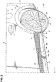
- FIG. 2 is an enlarged perspective view of a major part of FIG. 1
- FIG. 3 is a sectional perspective view taken along line A-A of FIG. 1
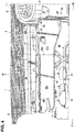
- FIG. 4 is a side view of a perspective view of a bottom face of the major part of FIG. 1 .
- a front door 1 as a side door which is configured to open or close a door opening formed at a vehicle front portion
- a rear door 2 as another side door which is configured to open or close another door opening formed at a vehicle rear portion.
- the front door 1 is particularly equipped with a door outer handle 3
- the rear door 2 is particularly equipped with another door outer handle 4 similarly.
- a front fender panel 5 which covers a side of an engine room is particularly provided in front of the front door 1 , and a front wheel house 7 is integrally formed at a lower portion of the front fender panel 5 at a position near or corresponding to a front wheel 6 .
- a rear fender panel 8 which covers a side of a baggage compartment is particularly provided in back of the rear door 2 , and a rear wheel house 10 is integrally formed at a lower portion of the rear fender panel 8 at a position near or corresponding to a rear wheel 9 .
- a fuel rid 11 for fuel supply is particularly attached to the rear fender panel 8 .
- reference character 12 denotes a door mirror
- reference character 13 denotes a rear bumper face which is configured to extend rearwardly, going around a vehicle side portion.
- a floor panel 14 which forms a bottom face of a cabin is particularly provided, and one or more side sills, particularly a pair of right-and-left side sills 15 which extend in a vehicle longitudinal direction at a bottom or lower portion of the cabin at a position between a lower end portion of a rear edge of the front wheel house 7 and a lower end portion of a front edge of the rea wheel house 10 are provided at right-and-left both end portions of the floor panel 14 .
- a left-side side sill 15 is illustrated only in the figures.
- the side sill 15 is particularly a vehicle-body reinforcing member having a side-sill closed cross section 18 , which is formed by fixedly joining a side sill outer 16 and a side sill inner 17 and extends in the vehicle longitudinal direction.
- a center pillar 19 which extends in a vehicle vertical direction is particularly provided at a position facing to a rear end portion of the front door 1 and a front end portion of the rear door 2 .
- the center pillar 19 is particularly a vehicle-body reinforcing member having a center-pillar closed cross section 22 , which is formed by fixedly joining a center pillar outer 19 and a center pillar inner 21 and extends in the vehicle vertical direction, and a lower portion 20a of the center pillar outer 20 and a lower portion 21a of the center pillar inner 21 are fixed to an outward-side face portion of the side sill outer 16 .
- the rear side door 2 particularly comprises a door outer panel 23 and a door inner panel 24 , and a door inner space 25 is formed between the door outer panel 23 and the door inner panel 24 .
- a front floor under cover 26 and a rear floor under cover 27 which serve as a member for airflow straightening, are particularly provided at a side portion of a vehicle bottom portion which is positioned beside a tunnel portion such that these covers 26 , 27 are continuous from each other in the vehicle longitudinal direction.
- the floor under covers 26 , 27 particularly include flat airflow straitening faces 26a , 27a , respectively. Respective outward portions, in a vehicle width direction, of the floor under covers 26 , 27 , which are attached to a vehicle body, are particularly attached to the side sill inner 17 by using attaching members 28 , such as bolts and nuts, as shown in FIG. 3 .
- a front end portion 27b of the rear floor under cover 27 is particularly configured to overlap a rear end portion 26b of the front floor under cover 26 from above, and this overlap portion is fixedly fastened to a nut which is previously fixed to a roughly horizontal bottom portion of the side sill inner 17 by means of a bolt which is inserted from below.
- the vehicle of the present embodiment is particularly provided with a torsion-beam type of rear suspension 30 which comprises one or more, particularly a pair of right-and-left trailing arms extending in the longitudinal direction and a torsion beam 29 extending in the vehicle width direction and interconnecting the right-and-left trailing arms.
- a plate-shaped under cover 31 for airflow straightening is particularly attached to a free-end-side lower portion of the trailing arm such that this under cover 31 covers this free-end-side lower portion from below.
- reference characters 32 , 33 denote catalyst converters which are particularly provided at a midway part of an exhaust pipe 34 .
- a garnish 40 is provided to cover the side sill 15 over a range from the front wheel house 7 to and the rear wheel house 10 .
- This garnish 40 is provided with a protrusion portion 41 which protrudes outwardly, in the vehicle width direction, particularly, so as to suppress a side-face airflow flowing below a door maximum-width portion (see a beltline portion) of a side portion of the cabin from going around below a vehicle floor.
- the garnish 40 particularly comprises an upper piece portion 40a which extends in the vertical direction, a roughly-horizontal portion 40b which roughly horizontally extends outwardly, in the vehicle width direction, from a lower end of the upper piece portion 40a , a vertical face portion 40c which extends obliquely inwardly and downwardly from an outward side of the roughly-horizontal portion 40b and extends in the vehicle longitudinal direction along a lower portion of the rear door 2 and an outer face of the side sill 15 , a protruding face portion 40d which protrudes outwardly from a lower end of the vertical wall portion 40c and forms an upper face of the protrusion portion 41 , an outer piece portion 40e which extends downwardly from an outward end of the protruding face portion 40d , and a bottom face portion 40f which extends inwardly, in the vehicle width direction, from a lower end of the outer piece portion 40e and forms a lower face of the protruding portion 41 .
- a synthetic-resin-made attaching piece portion 40g is particularly integrally formed at the garnish 40 such that this attaching piece portion 40 extends vertically between a lower portion of the upper piece portion 40a and a middle portion, in the vertical direction, of the vertical face portion 40c on an inward side, in the vehicle width direction, of the garnish 40 .
- the attaching piece portion 40g is particularly attached to the center pillar outer 20 by means of clips 42 , whereby the garnish 40 is attached to the vehicle body.
- a part of the attaching piece portion 40g is illustrated in FIG. 3 , but there exist plural attachment points with the clips 42 along the longitudinal direction.
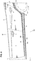
- FIG. 8 is a partial perspective view particularly showing a linear shape and a curved shape of the garnish 40 , and as shown in this figure, an outward end, in the vehicle width direction, of the protruding face portion 40d is particularly configured to be substantially linear over a range from the lower end of the rear edge of the front wheel house 7 to the lower end portion of the front edge of the rear wheel house 10 .
- the outer piece portion 40e of the garnish 40 is configured to be substantially linear over the range from the lower end of the rear edge of the front wheel house 7 to the lower end portion of the front edge of the rear wheel house 10 .
- an inward end, in the vehicle width direction, of the protruding face portion 40d and/or the vertical face portion 40c are configured to be curved such that respective middle portions, in the vehicle longitudinal direction, thereof are positioned inwardly in the vehicle width direction, which particularly match a shape of a lower portion of the front door 1 and/or a shape of a lower portion of the rear door 2 , respectively.
- the side-face airflow flowing below the door maximum-width portion is suppressed from going around below the vehicle floor by means of the protruding face portion 40d which forms the upper face of the protrusion portion 41 , thereby securing the airflow straightening effect, and also the vehicle design quality is secured by the curved shapes of the inward end of the protruding face portion 40d and the vertical face portion 40c .
- FIG. 5 is a perspective view of the garnish and a tire deflator
- FIG. 6 is a bottom face view of FIG. 6
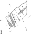
- FIG. 7 is a perspective view of the garnish and the tire deflator.
- a plate-shaped tire deflector 50 is particularly provided at the lower end portion of the front edge of the rear wheel house 10 which corresponds to a position, in the vertical direction, of a rear end portion of the protrusion portion 41 of the garnish 40 .
- the tire deflector 50 is particularly a traveling-air deflecting means for deflecting a side-face airflow e which flows above the protrusion portion 41 of the garnish 40 (see a bold arrow in FIG. 2 ) such that this airflow e is turned toward an outward side, in the vehicle width direction, particularly, so as not to flow into the rear wheel house 10 (see a bold arrow e2 part in Fig. 2 ) and flows along or adheres to an outer face 9a of a tire wheel of the rear wheel 9 (see a bold arrow e3 part in Fig. 2 ).
- the tire deflector 50 particularly comprises, as shown in FIG. 5 , a upper-side plate-shaped portion 51 which is positioned above a rear end of the outer piece portion 40e of the garnish 40 , a lower-side plate-shaped portion 52 which is positioned below the rear end of the outer piece portion 40e and extends downwardly from a lower face portion of the side sill 15 , and a attaching piece portion 53 (a so-called attachment base) which extends forwardly from an upper portion of the lower-side plate-shaped portion 52 so as to match the bottom face portion 40f of the garnish 40 , which are integrally made of synthetic resin, such as polypropylene.
- the attaching piece portion 53 of the tire deflector 50 is particularly fixedly attached to the bottom face portion 40f of the garnish 40 by using one or plural clips 54 .
- the lower-side plate-shaped portion 52 is particularly provided to be inclined such that an outward end, in the vehicle width direction, of the lower-side plate-shaped portion 52 is positioned on a rearward side, in the vehicle longitudinal direction, of an inward end, in the vehicle width direction, of the lower-side plate-shaped portion 52 .
- a portion of the upper-side plate-shaped portion 51 which protrudes toward the outward side, in the vehicle width direction, beyond the garnish 40 is particularly provided to be inclined similarly.
- an inclined angle ⁇ relative to a vehicle-width-direction line L of the plate-shaped portions 51 , 52 is set within a range of about 8 - about 12 degrees, preferably set at about 10 degrees.
- the tire deflector 50 is configured to abut with and be fixed to a rear end face of the garnish 40 . Thereby, positioning of the both members 40 , 50 is attained merely by making the deflector 50 abut with the rear end face of the garnish 40 , so that the assembling quality of the tire deflector 50 to the garnish 40 is improved.
- upwardly-recced attachment seats 40h for attaching the garnish 40 to a lower face of the side sill 15 are formed at respective portions of the bottom face portion 40f of the garnish 40 which are positioned at an inward side, in the vehicle width direction, of the bottom face portion 40f and spaced apart from each other in the vehicle longitudinal direction. Since the attachment seats 40h are configured to be recessed upwardly from the bottom face portion 40f of the garnish 40 , it is prevented that the airflow flowing below the garnish 40 is disturbed by attaching members which attach the garnish attachment seats 40h to the side sill 15 .
- an arrow F shows a vehicle forward side
- an arrow R shows a vehicle rearward side
- an arrow IN shows in an inward side, in the vehicle width direction, of the vehicle
- an arrow OUT shows an outward side, in the vehicle width direction, of the vehicle
- arrow UP shows a vehicle upward side
- the vehicle-body side face structure of the present embodiment comprises the side sill 15 extending in the vehicle longitudinal direction at the lower portion of the cabin at the position located between the lower end portion of the rear edge of the front wheel house 7 and the lower end portion of the front edge of the rear wheel house 10 , and the garnish 40 provided to cover the side sill 15 over the range from the front wheel house 7 to the rear wheel house 10 , wherein the garnish 40 is provided with the protrusion portion 41 which protrudes outwardly, in the vehicle width direction, so as to suppress the side-face airflow e flowing below the door maximum-width portion of the side portion of the cabin from going around below the vehicle floor, and the plate-shaped tire deflector 50 is provided at the lower end portion of the front edge of the rear wheel house 10 which corresponds to the position, in the vertical direction, of the rear end portion of the protrusion portion 41 of the garnish 40 , the tire deflector 50 being configured to deflect the side-face airflow flowing above the protrusion portion 41 such that the side-face airflow is
- the side-face airflow flowing below the door maximum-width portion of the side portion of the cabin can be properly suppressed from going around below the vehicle floor by means of the above-described protrusion portion 41 , and also the situation where the above-described side-face airflow e is deflected upwardly and becomes so strong that it flows into the rear wheel house 10 can be properly suppressed by means of the above-described tire deflector 50 , thereby reducing disturbance of the vehicle rear airflow properly.
- the garnish 40 comprises the vertical face portion 40c which extends in the vehicle longitudinal direction along the lower portion of the door and the outer face of the side sill 15 and the protruding face portion 40d which protrudes outwardly, in the vehicle width direction, of the vertical face portion 40c and forms the upper face of the protrusion portion 41
- the outward end, in the vehicle width direction, of the protruding face portion 40d is configured to be linear over the range from the lower end portion of the rear edge of the front wheel house 7 and to the lower end portion of the front edge of the rear wheel house 10
- the inward end, in the vehicle width direction, of the protruding face portion 40d and the vertical face portion 40c are configured to be curved such that the respective middle portions, in the vehicle longitudinal direction, thereof are curved inwardly, in the vehicle width direction, so as to correspond to the shape of the lower portion of the door (see FIG. 8 ).
- the side-face airflow flowing below the door maximum-width portion can be properly suppressed from going around below the vehicle floor by means of the protruding face portion 40d forming the upper face of the protrusion portion 41 , thereby properly securing the airflow straightening effect, and also the vehicle design quality can be properly secured by the curved shapes of the inward end of the protruding face portion 40d and the vertical face portion 40c .
- the tire deflector 50 includes the plate-shaped portion (see the lower-side plate-shaped portion 52 ) which is configured to extend downwardly from the lower face of the side sill 15 , this plate-shaped portion 52 is inclined such that the outward end, in the vehicle width direction, thereof is positioned on the rearward side, in the vehicle longitudinal direction, of the inward end, in the vehicle width direction, thereof (see FIG. 6 ).
- the plate-shaped portion (the lower-side plate-shaped portion 52 ) of the tire deflector 50 is arranged in the so-called rearwardly inclined state, the side-face airflow can be made to adhere to the outer face 9a of the tire wheel securely.
- the tire deflector 50 is configured to abut with and be fixed to the rear end face of the garnish 40 (see FIG. 5 ).
- the assembling quality of the tire deflector 50 to the garnish 40 can be properly improved.
- the plate-shaped portion of the present invention corresponds to the lower-side plate-shaped portion 52 of the embodiment.
- the present invention is not limited to the above-described embodiment only.
Landscapes
- Engineering & Computer Science (AREA)
- Chemical & Material Sciences (AREA)
- Combustion & Propulsion (AREA)
- Transportation (AREA)
- Mechanical Engineering (AREA)
- Physics & Mathematics (AREA)
- Fluid Mechanics (AREA)
- Body Structure For Vehicles (AREA)
Abstract
Description
- The present invention relates to a vehicle-body side face structure and a vehicle, in particular, relates to the vehicle-body side face structure which comprises a side sill extending in a vehicle longitudinal direction at a lower portion of a cabin at a position located between a lower end portion of a rear edge of a front wheel house and a lower end portion of a front edge of a rear wheel house and a garnish provided to cover the side sill over a range from the front wheel house to the rear wheel house.
- In general, a vehicle is configured such that a width, in a vehicle width direction, of a beltline portion of each of a pair of right-and-left side doors is set to be the maximum and the width of the other part of the side door becomes smaller toward a downward side of the side door.
- Herein, it has been found that this structure has a problem in that a side-face airflow (traveling air) flowing below the above-described door maximum-width portion (beltline portion) is so drawn into a high-speed airflow flowing down below a vehicle floor that this side-face airflow goes around a side sill and below the vehicle floor, so that the airflow below the vehicle floor is disturbed improperly.
- Then, it has been found that in a case where a protrusion portion which is configured to protrude outwardly in the vehicle width direction is provided at the side sill, the side-face airflow is suppressed from going around below the vehicle floor, but this side-face airflow is deflected upwardly and becomes so strong that it flows into the rear wheel house, so that a vehicle rear airflow is disturbed improperly.
- Meanwhile, Japanese Patent Laid-Open Publication No.
2004-106585 - Accordingly, an object of the present invention is reducing disturbance of the vehicle rear airflow.
- This object is solved by the vehicle-body side face structure according to the present invention of the independent claim. Preferred embodiments of the present invention are subject of the other dependent claims.
- The present invention is a vehicle-body side face structure, including a side sill extending in a vehicle longitudinal direction at a lower portion of a cabin at a position located between a lower end portion of a rear edge of a front wheel house and a lower end portion of a front edge of a rear wheel house, and a garnish provided to cover the side sill over a range from the front wheel house to the rear wheel house. The garnish is provided with a protrusion portion which protrudes outwardly, in a vehicle width direction. A plate-shaped tire deflector is provided at the lower end portion of the front edge of the rear wheel house which corresponds to a position, in a vertical direction, of a rear end portion of the protrusion portion of the garnish. The tire deflector is configured to deflect a side-face airflow flowing above the protrusion portion such that the side-face airflow is turned toward an outward side, in the vehicle width direction.
- Particularly, the protrusion portion is configured to suppress or prevent a side-face airflow flowing below a door maximum-width portion of a side portion of the cabin from going around below a vehicle floor.
- Further particularly, the tire deflector is configured to deflect the side-face airflow flowing above the protrusion portion such that the side-face airflow is turned toward the outward side, in the vehicle width direction, so as not to flow into the rear wheel house.
- Further particularly, the tire deflector is configured to deflect the side-face airflow flowing above the protrusion portion such that the side-face airflow is turned toward the outward side, in the vehicle width direction, and adheres to an outer face of a tire wheel of a rear wheel.
- Further particularly, the garnish includes a vertical face portion which extends in the vehicle longitudinal direction along a lower portion of a door and/or an outer face of the side sill.
- Further particularly, the garnish further includes a protruding face portion which protrudes outwardly, in the vehicle width direction, of the vertical face portion and forms an upper face of the protrusion portion.
- Further particularly, an outward end, in the vehicle width direction, of the protruding face portion is configured to be substantially linear over a range from the lower end portion of the rear edge of the front wheel house to the lower end portion of the front edge of the rear wheel house.
- Further particularly, at least one of an inward end, in the vehicle width direction, of the protruding face portion and the vertical face portion are configured to be curved such that respective middle portions, in the vehicle longitudinal direction, thereof are curved inwardly, in the vehicle width direction.
- Further particularly, at least one of an inward end, in the vehicle width direction, of the protruding face portion and the vertical face portion are configured to be curved so as to correspond to a shape of the lower portion of the door.
- Further particularly, the tire deflector includes a plate-shaped portion which is configured to extend downwardly from a lower face of the side sill.
- Further particularly, the plate-shaped portion is inclined such that an outward end, in the vehicle width direction, thereof is positioned on a rearward side, in the vehicle longitudinal direction, of an inward end, in the vehicle width direction, thereof.
- Further particularly, the tire deflector is configured to abut with and be fixed to a rear end face of the garnish.
- Further particularly, a vehicle includes the above vehicle-body side face structure, a front wheel, and a rear wheel.
- The present invention is a vehicle-body side face structure, comprising a side sill extending in a vehicle longitudinal direction at a lower portion of a cabin at a position located between a lower end portion of a rear edge of a front wheel house and a lower end portion of a front edge of a rear wheel house, and a garnish provided to cover the side sill over a range from the front wheel house to the rear wheel house, wherein the garnish is provided with a protrusion portion which protrudes outwardly, in a vehicle width direction, so as to suppress a side-face airflow flowing below a door maximum-width portion of a side portion of the cabin from going around below a vehicle floor, and a plate-shaped tire deflector is provided at the lower end portion of the front edge of the rear wheel house which corresponds to a position, in a vertical direction, of a rear end portion of the protrusion portion of the garnish, the tire deflector being configured to deflect a side-face airflow flowing above the protrusion portion such that the side-face airflow is turned toward an outward side, in the vehicle width direction, so as not to flow into the rear wheel house and adheres to an outer face of a tire wheel of a rear wheel.
- According to the present invention, the side-face airflow flowing below the door maximum-width portion of the side portion of the cabin can be properly suppressed from going around below the vehicle floor by means of the above-described protrusion portion, and also the situation where the above-described side-face airflow is deflected upwardly and becomes so strong that it flows into the rear wheel house can be properly suppressed by means of the above-described tire deflector, thereby reducing disturbance of the vehicle rear airflow properly.
- In an embodiment of the present invention, the garnish comprises a vertical face portion which extends in the vehicle longitudinal direction along a lower portion of a door and an outer face of the side sill and a protruding face portion which protrudes outwardly, in the vehicle width direction, of the vertical face portion and forms an upper face of the protrusion portion, an outward end, in the vehicle width direction, of the protruding face portion is configured to be linear over a range from the lower end portion of the rear edge of the front wheel house and to the lower end portion of the front edge of the rear wheel house, and an inward end, in the vehicle width direction, of the protruding face portion and the vertical face portion are configured to be curved such that respective middle portions, in the vehicle longitudinal direction, thereof are curved inwardly, in the vehicle width direction, so as to correspond to a shape of the lower portion of the door.
- According to this embodiment, the side-face airflow flowing below the door maximum-width portion can be properly suppressed from going around below the vehicle floor by means of the protruding face portion forming the upper face of the protrusion portion, thereby properly securing the airflow straightening effect, and also the vehicle design quality can be properly secured by the curved shapes of the inward end of the protruding face portion and the vertical face portion.
- In another embodiment of the present invention, the tire deflector includes a plate-shaped portion which is configured to extend downwardly from a lower face of the side sill, the plate-shaped portion is inclined such that an outward end, in the vehicle width direction, thereof is positioned on a rearward side, in the vehicle longitudinal direction, of an inward end, in the vehicle width direction, thereof.
- According to this embodiment, since the plate-shaped portion of the tire deflector is arranged in a so-called rearwardly-inclined state, the side-face airflow can be made to adhere to the outer face of the tire wheel securely.
- In another embodiment of the present invention, the tire deflector is configured to abut with and be fixed to a rear end face of the garnish.
- According to this embodiment, the assembling quality of the tire deflector to the garnish can be properly improved.
- Other features, aspects, and advantages of the present invention will become apparent from the following description which refers to the accompanying drawings.
-
FIG. 1 is a side view of a vehicle having a vehicle-body side face structure of the present invention. -
FIG. 2 is an enlarged perspective view of a major part ofFIG. 1 . -
FIG. 3 is a sectional perspective view taken along line A-A ofFIG. 1 . -
FIG. 4 is a perspective view of a bottom face of the major part ofFIG. 1 . -
FIG. 5 is a perspective view of a garnish and a tire deflector. -
FIG. 6 is a bottom face view ofFIG. 5 . -
FIG. 7 is a perspective view of the garnish and the tire deflector. -
FIG. 8 is a partial perspective view showing a linear shape and a curved shape of the garnish. - Hereafter, an embodiment of the present invention will be specifically described referring to the drawings.
- Figures show a vehicle-body side face structure.
FIG. 1 is a side view of a vehicle provided with the vehicle-body side face structure,FIG. 2 is an enlarged perspective view of a major part ofFIG. 1 ,FIG. 3 is a sectional perspective view taken along line A-A ofFIG. 1 , andFIG. 4 is a side view of a perspective view of a bottom face of the major part ofFIG. 1 . - As shown in
FIGS. 1 and2 , at a side portion of a vehicle body are provided one or more doors, particularly afront door 1 as a side door which is configured to open or close a door opening formed at a vehicle front portion and arear door 2 as another side door which is configured to open or close another door opening formed at a vehicle rear portion. Thefront door 1 is particularly equipped with a doorouter handle 3, and therear door 2 is particularly equipped with another door outer handle 4 similarly. - As shown in
FIG. 1 , afront fender panel 5 which covers a side of an engine room is particularly provided in front of thefront door 1, and afront wheel house 7 is integrally formed at a lower portion of thefront fender panel 5 at a position near or corresponding to afront wheel 6. - As shown in
FIG. 1 , arear fender panel 8 which covers a side of a baggage compartment is particularly provided in back of therear door 2, and arear wheel house 10 is integrally formed at a lower portion of therear fender panel 8 at a position near or corresponding to arear wheel 9. Afuel rid 11 for fuel supply is particularly attached to therear fender panel 8. InFIG. 1 ,reference character 12 denotes a door mirror, andreference character 13 denotes a rear bumper face which is configured to extend rearwardly, going around a vehicle side portion. - As shown in
FIG. 3 , afloor panel 14 which forms a bottom face of a cabin is particularly provided, and one or more side sills, particularly a pair of right-and-left side sills 15 which extend in a vehicle longitudinal direction at a bottom or lower portion of the cabin at a position between a lower end portion of a rear edge of thefront wheel house 7 and a lower end portion of a front edge of therea wheel house 10 are provided at right-and-left both end portions of thefloor panel 14. Herein, a left-side side sill 15 is illustrated only in the figures. - As shown in
FIG. 3 , theside sill 15 is particularly a vehicle-body reinforcing member having a side-sill closedcross section 18, which is formed by fixedly joining a side sill outer 16 and a side sill inner 17 and extends in the vehicle longitudinal direction. Acenter pillar 19 which extends in a vehicle vertical direction is particularly provided at a position facing to a rear end portion of thefront door 1 and a front end portion of therear door 2. - As shown in
FIG. 3 , thecenter pillar 19 is particularly a vehicle-body reinforcing member having a center-pillar closed cross section 22, which is formed by fixedly joining a center pillar outer 19 and a center pillar inner 21 and extends in the vehicle vertical direction, and alower portion 20a of the center pillar outer 20 and alower portion 21a of the center pillar inner 21 are fixed to an outward-side face portion of the side sill outer 16. - Meanwhile, as shown in
FIG. 3 , therear side door 2 particularly comprises a doorouter panel 23 and a doorinner panel 24, and a doorinner space 25 is formed between the doorouter panel 23 and the doorinner panel 24. - As shown in
FIG. 4 , a front floor undercover 26 and a rear floor undercover 27, which serve as a member for airflow straightening, are particularly provided at a side portion of a vehicle bottom portion which is positioned beside a tunnel portion such that these covers 26, 27 are continuous from each other in the vehicle longitudinal direction. - The floor under
covers faces covers members 28, such as bolts and nuts, as shown inFIG. 3 . - Specifically, a
front end portion 27b of the rear floor undercover 27 is particularly configured to overlap arear end portion 26b of the front floor undercover 26 from above, and this overlap portion is fixedly fastened to a nut which is previously fixed to a roughly horizontal bottom portion of the side sill inner 17 by means of a bolt which is inserted from below. - As shown in
FIG. 4 , the vehicle of the present embodiment is particularly provided with a torsion-beam type ofrear suspension 30 which comprises one or more, particularly a pair of right-and-left trailing arms extending in the longitudinal direction and atorsion beam 29 extending in the vehicle width direction and interconnecting the right-and-left trailing arms. A plate-shaped undercover 31 for airflow straightening is particularly attached to a free-end-side lower portion of the trailing arm such that this undercover 31 covers this free-end-side lower portion from below. InFIG. 4 ,reference characters exhaust pipe 34. - As shown in
FIGS. 1 and3 , agarnish 40 is provided to cover theside sill 15 over a range from thefront wheel house 7 to and therear wheel house 10. Thisgarnish 40 is provided with aprotrusion portion 41 which protrudes outwardly, in the vehicle width direction, particularly, so as to suppress a side-face airflow flowing below a door maximum-width portion (see a beltline portion) of a side portion of the cabin from going around below a vehicle floor. - As shown in
FIG. 3 , thegarnish 40 particularly comprises anupper piece portion 40a which extends in the vertical direction, a roughly-horizontal portion 40b which roughly horizontally extends outwardly, in the vehicle width direction, from a lower end of theupper piece portion 40a, avertical face portion 40c which extends obliquely inwardly and downwardly from an outward side of the roughly-horizontal portion 40b and extends in the vehicle longitudinal direction along a lower portion of therear door 2 and an outer face of theside sill 15, a protrudingface portion 40d which protrudes outwardly from a lower end of thevertical wall portion 40c and forms an upper face of theprotrusion portion 41, anouter piece portion 40e which extends downwardly from an outward end of the protrudingface portion 40d, and abottom face portion 40f which extends inwardly, in the vehicle width direction, from a lower end of theouter piece portion 40e and forms a lower face of the protrudingportion 41. - A synthetic-resin-made attaching
piece portion 40g is particularly integrally formed at thegarnish 40 such that this attachingpiece portion 40 extends vertically between a lower portion of theupper piece portion 40a and a middle portion, in the vertical direction, of thevertical face portion 40c on an inward side, in the vehicle width direction, of thegarnish 40. As shown inFIG. 3 , the attachingpiece portion 40g is particularly attached to the center pillar outer 20 by means ofclips 42, whereby thegarnish 40 is attached to the vehicle body. Herein, a part of the attachingpiece portion 40g is illustrated inFIG. 3 , but there exist plural attachment points with theclips 42 along the longitudinal direction. -
FIG. 8 is a partial perspective view particularly showing a linear shape and a curved shape of thegarnish 40, and as shown in this figure, an outward end, in the vehicle width direction, of the protrudingface portion 40d is particularly configured to be substantially linear over a range from the lower end of the rear edge of thefront wheel house 7 to the lower end portion of the front edge of therear wheel house 10. In other words, theouter piece portion 40e of thegarnish 40 is configured to be substantially linear over the range from the lower end of the rear edge of thefront wheel house 7 to the lower end portion of the front edge of therear wheel house 10. - Further, as shown in
FIG. 8 , an inward end, in the vehicle width direction, of the protrudingface portion 40d and/or thevertical face portion 40c are configured to be curved such that respective middle portions, in the vehicle longitudinal direction, thereof are positioned inwardly in the vehicle width direction, which particularly match a shape of a lower portion of thefront door 1 and/or a shape of a lower portion of therear door 2, respectively. - Thereby, the side-face airflow flowing below the door maximum-width portion is suppressed from going around below the vehicle floor by means of the protruding
face portion 40d which forms the upper face of theprotrusion portion 41, thereby securing the airflow straightening effect, and also the vehicle design quality is secured by the curved shapes of the inward end of the protrudingface portion 40d and thevertical face portion 40c. -
FIG. 5 is a perspective view of the garnish and a tire deflator,FIG. 6 is a bottom face view ofFIG. 6 , andFIG. 7 is a perspective view of the garnish and the tire deflator. As shown inFIGS. 2 - 8 , a plate-shapedtire deflector 50 is particularly provided at the lower end portion of the front edge of therear wheel house 10 which corresponds to a position, in the vertical direction, of a rear end portion of theprotrusion portion 41 of thegarnish 40. - The
tire deflector 50 is particularly a traveling-air deflecting means for deflecting a side-face airflow e which flows above theprotrusion portion 41 of the garnish 40 (see a bold arrow inFIG. 2 ) such that this airflow e is turned toward an outward side, in the vehicle width direction, particularly, so as not to flow into the rear wheel house 10 (see a bold arrow e2 part inFig. 2 ) and flows along or adheres to anouter face 9a of a tire wheel of the rear wheel 9 (see a bold arrow e3 part inFig. 2 ). - The
tire deflector 50 particularly comprises, as shown inFIG. 5 , a upper-side plate-shapedportion 51 which is positioned above a rear end of theouter piece portion 40e of thegarnish 40, a lower-side plate-shapedportion 52 which is positioned below the rear end of theouter piece portion 40e and extends downwardly from a lower face portion of theside sill 15, and a attaching piece portion 53 (a so-called attachment base) which extends forwardly from an upper portion of the lower-side plate-shapedportion 52 so as to match thebottom face portion 40f of thegarnish 40, which are integrally made of synthetic resin, such as polypropylene. - As shown in
FIGS. 5 ,6 and7 , the attachingpiece portion 53 of thetire deflector 50 is particularly fixedly attached to thebottom face portion 40f of thegarnish 40 by using one orplural clips 54. - As shown in the bottom view of
FIG. 6 , the lower-side plate-shapedportion 52 is particularly provided to be inclined such that an outward end, in the vehicle width direction, of the lower-side plate-shapedportion 52 is positioned on a rearward side, in the vehicle longitudinal direction, of an inward end, in the vehicle width direction, of the lower-side plate-shapedportion 52. As shown inFIGS. 2 and5 , a portion of the upper-side plate-shapedportion 51 which protrudes toward the outward side, in the vehicle width direction, beyond thegarnish 40 is particularly provided to be inclined similarly. - As shown in
FIG. 6 , an inclined angle θ relative to a vehicle-width-direction line L of the plate-shapedportions outer face 9a of the tire wheel securely. - Further, as shown in
FIG. 5 , thetire deflector 50 is configured to abut with and be fixed to a rear end face of thegarnish 40. Thereby, positioning of the bothmembers deflector 50 abut with the rear end face of thegarnish 40, so that the assembling quality of thetire deflector 50 to thegarnish 40 is improved. - Herein, upwardly-recced
attachment seats 40h for attaching thegarnish 40 to a lower face of theside sill 15 are formed at respective portions of thebottom face portion 40f of thegarnish 40 which are positioned at an inward side, in the vehicle width direction, of thebottom face portion 40f and spaced apart from each other in the vehicle longitudinal direction. Since theattachment seats 40h are configured to be recessed upwardly from thebottom face portion 40f of thegarnish 40, it is prevented that the airflow flowing below thegarnish 40 is disturbed by attaching members which attach thegarnish attachment seats 40h to theside sill 15. - Herein, while the above-described embodiment shows a left-side vehicle structure, the vehicle-body side structure is symmetrical laterally substantially. In the figures, an arrow F shows a vehicle forward side, an arrow R shows a vehicle rearward side, an arrow IN shows in an inward side, in the vehicle width direction, of the vehicle, an arrow OUT shows an outward side, in the vehicle width direction, of the vehicle, and arrow UP shows a vehicle upward side.
- As described above, the vehicle-body side face structure of the present embodiment comprises the side sill 15 extending in the vehicle longitudinal direction at the lower portion of the cabin at the position located between the lower end portion of the rear edge of the front wheel house 7 and the lower end portion of the front edge of the rear wheel house 10, and the garnish 40 provided to cover the side sill 15 over the range from the front wheel house 7 to the rear wheel house 10, wherein the garnish 40 is provided with the protrusion portion 41 which protrudes outwardly, in the vehicle width direction, so as to suppress the side-face airflow e flowing below the door maximum-width portion of the side portion of the cabin from going around below the vehicle floor, and the plate-shaped tire deflector 50 is provided at the lower end portion of the front edge of the rear wheel house 10 which corresponds to the position, in the vertical direction, of the rear end portion of the protrusion portion 41 of the garnish 40, the tire deflector 50 being configured to deflect the side-face airflow flowing above the protrusion portion 41 such that the side-face airflow is turned toward the outward side, in the vehicle width direction, so as not to flow into the rear wheel house 10 and adheres to the outer face 9a of the tire wheel of the rear wheel 9 (see
FIGS. 1 - 3 ). - According to the present structure, the side-face airflow flowing below the door maximum-width portion of the side portion of the cabin can be properly suppressed from going around below the vehicle floor by means of the above-described
protrusion portion 41, and also the situation where the above-described side-face airflow e is deflected upwardly and becomes so strong that it flows into therear wheel house 10 can be properly suppressed by means of the above-describedtire deflector 50, thereby reducing disturbance of the vehicle rear airflow properly. - In the embodiment of the present invention, the
garnish 40 comprises thevertical face portion 40c which extends in the vehicle longitudinal direction along the lower portion of the door and the outer face of theside sill 15 and the protrudingface portion 40d which protrudes outwardly, in the vehicle width direction, of thevertical face portion 40c and forms the upper face of theprotrusion portion 41, the outward end, in the vehicle width direction, of the protrudingface portion 40d is configured to be linear over the range from the lower end portion of the rear edge of thefront wheel house 7 and to the lower end portion of the front edge of therear wheel house 10, and the inward end, in the vehicle width direction, of the protrudingface portion 40d and thevertical face portion 40c are configured to be curved such that the respective middle portions, in the vehicle longitudinal direction, thereof are curved inwardly, in the vehicle width direction, so as to correspond to the shape of the lower portion of the door (seeFIG. 8 ). - According to this structure, the side-face airflow flowing below the door maximum-width portion can be properly suppressed from going around below the vehicle floor by means of the protruding
face portion 40d forming the upper face of theprotrusion portion 41, thereby properly securing the airflow straightening effect, and also the vehicle design quality can be properly secured by the curved shapes of the inward end of the protrudingface portion 40d and thevertical face portion 40c. - In the embodiment of the present invention, the
tire deflector 50 includes the plate-shaped portion (see the lower-side plate-shaped portion 52) which is configured to extend downwardly from the lower face of theside sill 15, this plate-shapedportion 52 is inclined such that the outward end, in the vehicle width direction, thereof is positioned on the rearward side, in the vehicle longitudinal direction, of the inward end, in the vehicle width direction, thereof (seeFIG. 6 ). - According to this structure, since the plate-shaped portion (the lower-side plate-shaped portion 52) of the
tire deflector 50 is arranged in the so-called rearwardly inclined state, the side-face airflow can be made to adhere to theouter face 9a of the tire wheel securely. - In the embodiment of the present invention, the
tire deflector 50 is configured to abut with and be fixed to the rear end face of the garnish 40 (seeFIG. 5 ). - According to this structure, the assembling quality of the
tire deflector 50 to thegarnish 40 can be properly improved. - In correspondence of the present invention to the above-described embodiment, the plate-shaped portion of the present invention corresponds to the lower-side plate-shaped
portion 52 of the embodiment. However, the present invention is not limited to the above-described embodiment only.
Claims (13)
- A vehicle-body side face structure, comprising:a side sill (15) extending in a vehicle longitudinal direction at a lower portion of a cabin at a position located between a lower end portion of a rear edge of a front wheel house (7) and a lower end portion of a front edge of a rear wheel house (10); anda garnish (40) provided to cover the side sill (15) over a range from the front wheel house (7) to the rear wheel house (10),whereinsaid garnish (40) is provided with a protrusion portion (41) which protrudes outwardly, in a vehicle width direction,a plate-shaped tire deflector (50) is provided at said lower end portion of the front edge of the rear wheel house (10) which corresponds to a position, in a vertical direction, of a rear end portion of said protrusion portion (41) of the garnish (40), andthe tire deflector (50) is configured to deflect a side-face airflow flowing above the protrusion portion (41) such that the side-face airflow is turned toward an outward side, in the vehicle width direction.
- The vehicle-body side face structure of claim 1, wherein the protrusion portion (41) is configured to suppress or prevent a side-face airflow flowing below a door maximum-width portion of a side portion of the cabin from going around below a vehicle floor.
- The vehicle-body side face structure of claim 1 or 2, wherein the tire deflector (50) is configured to deflect the side-face airflow flowing above the protrusion portion (41) such that the side-face airflow is turned toward the outward side, in the vehicle width direction, so as not to flow into the rear wheel house (10).
- The vehicle-body side face structure of any one of the preceding claims, wherein the tire deflector (50) is configured to deflect the side-face airflow flowing above the protrusion portion (41) such that the side-face airflow is turned toward the outward side, in the vehicle width direction, and adheres to an outer face (9a) of a tire wheel of a rear wheel (9).
- The vehicle-body side face structure of any of one of the preceding claims, wherein said garnish (40) comprises a vertical face portion (40c) which extends in the vehicle longitudinal direction along a lower portion of a door (1, 2) and/or an outer face of said side sill (15).
- The vehicle-body side face structure of claim 5, wherein said garnish (40) further comprises a protruding face portion (40d) which protrudes outwardly, in the vehicle width direction, of said vertical face portion (40c) and forms an upper face of said protrusion portion (41).
- The vehicle-body side face structure of claim 6, wherein an outward end, in the vehicle width direction, of said protruding face portion (40d) is configured to be substantially linear over a range from the lower end portion of the rear edge of the front wheel house (7) to the lower end portion of the front edge of the rear wheel house (10).
- The vehicle-body side face structure of claim 6 or 7, wherein at least one of an inward end, in the vehicle width direction, of said protruding face portion (40d) and said vertical face portion (40c) are configured to be curved such that respective middle portions, in the vehicle longitudinal direction, thereof are curved inwardly, in the vehicle width direction.
- The vehicle-body side face structure of any one of claims 6 to 8, wherein at least one of an inward end, in the vehicle width direction, of said protruding face portion (40d) and said vertical face portion (40c) are configured to be curved so as to correspond to a shape of the lower portion of the door (1, 2).
- The vehicle-body side face structure of any one of the preceding claims, wherein said tire deflector (50) includes a plate-shaped portion (52) which is configured to extend downwardly from a lower face of said side sill (15).
- The vehicle-body side face structure of claim 10, wherein the plate-shaped portion (52) is inclined such that an outward end, in the vehicle width direction, thereof is positioned on a rearward side, in the vehicle longitudinal direction, of an inward end, in the vehicle width direction, thereof.
- The vehicle-body side face structure of any one of the preceding claims, wherein said tire deflector (50) is configured to abut with and be fixed to a rear end face of said garnish (40).
- A vehicle, comprising:the vehicle-body side face structure of any one of the preceding claims;a front wheel (6); anda rear wheel (9).
Applications Claiming Priority (1)
| Application Number | Priority Date | Filing Date | Title |
|---|---|---|---|
| JP2018056448A JP7031414B2 (en) | 2018-03-23 | 2018-03-23 | Body side structure |
Publications (1)
| Publication Number | Publication Date |
|---|---|
| EP3543091A1 true EP3543091A1 (en) | 2019-09-25 |
Family
ID=65818306
Family Applications (1)
| Application Number | Title | Priority Date | Filing Date |
|---|---|---|---|
| EP19163410.4A Withdrawn EP3543091A1 (en) | 2018-03-23 | 2019-03-18 | Vehicle-body side face structure |
Country Status (4)
| Country | Link |
|---|---|
| US (1) | US10906599B2 (en) |
| EP (1) | EP3543091A1 (en) |
| JP (1) | JP7031414B2 (en) |
| CN (1) | CN110294028B (en) |
Families Citing this family (2)
| Publication number | Priority date | Publication date | Assignee | Title |
|---|---|---|---|---|
| JP7515783B2 (en) | 2020-11-24 | 2024-07-16 | マツダ株式会社 | Vehicle side body structure |
| US11702151B2 (en) * | 2020-12-02 | 2023-07-18 | Fca Us Llc | Aerodynamic vehicle side step |
Citations (6)
| Publication number | Priority date | Publication date | Assignee | Title |
|---|---|---|---|---|
| JPS59174969U (en) * | 1983-05-11 | 1984-11-22 | 関東自動車工業株式会社 | car body structure |
| JP2004106585A (en) | 2002-09-13 | 2004-04-08 | Fuji Heavy Ind Ltd | Flap mounting structure |
| GB2463742A (en) * | 2008-09-29 | 2010-03-31 | Honda Access Kk | Side under spoiler mounting structure |
| WO2015034022A1 (en) * | 2013-09-04 | 2015-03-12 | 本田技研工業株式会社 | Vehicle body lateral structure |
| WO2015072543A1 (en) * | 2013-11-15 | 2015-05-21 | 本田技研工業株式会社 | Vehicle body side portion structure |
| JP2017074905A (en) * | 2015-10-16 | 2017-04-20 | マツダ株式会社 | Undercarriage of the vehicle |
Family Cites Families (12)
| Publication number | Priority date | Publication date | Assignee | Title |
|---|---|---|---|---|
| JPS63185785U (en) * | 1987-05-25 | 1988-11-29 | ||
| JPS6419585U (en) * | 1987-07-28 | 1989-01-31 | ||
| JP3014109U (en) | 1995-01-30 | 1995-08-01 | 技研株式会社 | Side sill protector with mat guard for automobiles |
| JP3829332B2 (en) * | 2004-03-31 | 2006-10-04 | 株式会社ホンダアクセス | Side under spoiler mounting structure |
| JP4425692B2 (en) * | 2004-05-11 | 2010-03-03 | 本田技研工業株式会社 | Side sill garnish mounting structure |
| JP2008280015A (en) | 2007-05-14 | 2008-11-20 | Mazda Motor Corp | Rear side spoiler |
| JP5608489B2 (en) | 2010-09-10 | 2014-10-15 | 富士重工業株式会社 | Vehicle rectifier |
| ITBO20120089A1 (en) | 2012-02-24 | 2013-08-25 | Ferrari Spa | METHOD OF CONTROL OF A HIGH PERFORMANCE ROAD VEHICLE PROVIDED WITH A REAR BULB WITH AT LEAST ONE MOBILE WING ELEMENT |
| JP2014084035A (en) | 2012-10-25 | 2014-05-12 | Faltec Co Ltd | Side sill fitting member |
| JP6191550B2 (en) * | 2014-06-10 | 2017-09-06 | トヨタ自動車株式会社 | Aerodynamic structure for vehicles |
| DE102015113011B4 (en) * | 2015-08-07 | 2024-01-11 | Dr. Ing. H.C. F. Porsche Aktiengesellschaft | Motor vehicle with a wheel arch |
| JP6644977B2 (en) | 2016-05-27 | 2020-02-12 | トヨタ車体株式会社 | Aerodynamic components |
-
2018
- 2018-03-23 JP JP2018056448A patent/JP7031414B2/en active Active
-
2019
- 2019-03-08 CN CN201910175857.XA patent/CN110294028B/en active Active
- 2019-03-18 EP EP19163410.4A patent/EP3543091A1/en not_active Withdrawn
- 2019-03-22 US US16/362,183 patent/US10906599B2/en active Active
Patent Citations (6)
| Publication number | Priority date | Publication date | Assignee | Title |
|---|---|---|---|---|
| JPS59174969U (en) * | 1983-05-11 | 1984-11-22 | 関東自動車工業株式会社 | car body structure |
| JP2004106585A (en) | 2002-09-13 | 2004-04-08 | Fuji Heavy Ind Ltd | Flap mounting structure |
| GB2463742A (en) * | 2008-09-29 | 2010-03-31 | Honda Access Kk | Side under spoiler mounting structure |
| WO2015034022A1 (en) * | 2013-09-04 | 2015-03-12 | 本田技研工業株式会社 | Vehicle body lateral structure |
| WO2015072543A1 (en) * | 2013-11-15 | 2015-05-21 | 本田技研工業株式会社 | Vehicle body side portion structure |
| JP2017074905A (en) * | 2015-10-16 | 2017-04-20 | マツダ株式会社 | Undercarriage of the vehicle |
Also Published As
| Publication number | Publication date |
|---|---|
| JP7031414B2 (en) | 2022-03-08 |
| JP2019166983A (en) | 2019-10-03 |
| CN110294028A (en) | 2019-10-01 |
| CN110294028B (en) | 2022-06-28 |
| US20190291791A1 (en) | 2019-09-26 |
| US10906599B2 (en) | 2021-02-02 |
Similar Documents
| Publication | Publication Date | Title |
|---|---|---|
| EP3702251B1 (en) | Rear vehicle-body structure and vehicle | |
| JP6090241B2 (en) | Upper body structure of a car with sunroof | |
| US9248865B2 (en) | Vehicle body front structure | |
| EP3543093B1 (en) | Vehicle-body lower face structure | |
| US6648401B2 (en) | Motor vehicle body with wheelhouse/underbody reinforcement | |
| US10112653B2 (en) | Vehicle lower structure | |
| JP2001334955A (en) | Vehicle door reinforcement structure | |
| US20170233009A1 (en) | Vehicle body structure | |
| EP3543094B1 (en) | Vehicle-body lower face structure | |
| US10899388B2 (en) | Vehicle-body lower face structure | |
| US10906599B2 (en) | Vehicle-body side face structure | |
| US11420576B2 (en) | Vehicle body lower structure of vehicle | |
| JP6304200B2 (en) | Rear body structure of automobile | |
| JP7234515B2 (en) | Body front structure | |
| JP7797806B2 (en) | Vehicle lower body structure | |
| CN121158052A (en) | Vehicle body structure | |
| US10569805B2 (en) | Frame assembly for a vehicle and vehicle having same | |
| JPH08268329A (en) | Car upper body structure | |
| JP2009227063A (en) | Assist grip mounting structure | |
| JP2019182320A (en) | Vehicle body lower surface structure | |
| JP2019166989A (en) | Vehicle body lower structure | |
| JP3668060B2 (en) | Front body structure of automobile | |
| JP6537182B2 (en) | Wind noise reduction structure of vehicle | |
| JPH0651072U (en) | Car side body structure | |
| JP5955704B2 (en) | Front end structure of the vehicle |
Legal Events
| Date | Code | Title | Description |
|---|---|---|---|
| PUAI | Public reference made under article 153(3) epc to a published international application that has entered the european phase |
Free format text: ORIGINAL CODE: 0009012 |
|
| STAA | Information on the status of an ep patent application or granted ep patent |
Free format text: STATUS: THE APPLICATION HAS BEEN PUBLISHED |
|
| AK | Designated contracting states |
Kind code of ref document: A1 Designated state(s): AL AT BE BG CH CY CZ DE DK EE ES FI FR GB GR HR HU IE IS IT LI LT LU LV MC MK MT NL NO PL PT RO RS SE SI SK SM TR |
|
| AX | Request for extension of the european patent |
Extension state: BA ME |
|
| STAA | Information on the status of an ep patent application or granted ep patent |
Free format text: STATUS: REQUEST FOR EXAMINATION WAS MADE |
|
| 17P | Request for examination filed |
Effective date: 20200312 |
|
| RBV | Designated contracting states (corrected) |
Designated state(s): AL AT BE BG CH CY CZ DE DK EE ES FI FR GB GR HR HU IE IS IT LI LT LU LV MC MK MT NL NO PL PT RO RS SE SI SK SM TR |
|
| GRAP | Despatch of communication of intention to grant a patent |
Free format text: ORIGINAL CODE: EPIDOSNIGR1 |
|
| STAA | Information on the status of an ep patent application or granted ep patent |
Free format text: STATUS: GRANT OF PATENT IS INTENDED |
|
| RIC1 | Information provided on ipc code assigned before grant |
Ipc: B62D 35/00 20060101AFI20201223BHEP Ipc: B62D 35/02 20060101ALI20201223BHEP |
|
| INTG | Intention to grant announced |
Effective date: 20210126 |
|
| STAA | Information on the status of an ep patent application or granted ep patent |
Free format text: STATUS: THE APPLICATION IS DEEMED TO BE WITHDRAWN |
|
| 18D | Application deemed to be withdrawn |
Effective date: 20210608 |