EP3542914B1 - Verfahren und vorrichtung zur aussonderung von metallhaltigen materialien - Google Patents
Verfahren und vorrichtung zur aussonderung von metallhaltigen materialien Download PDFInfo
- Publication number
- EP3542914B1 EP3542914B1 EP19162141.6A EP19162141A EP3542914B1 EP 3542914 B1 EP3542914 B1 EP 3542914B1 EP 19162141 A EP19162141 A EP 19162141A EP 3542914 B1 EP3542914 B1 EP 3542914B1
- Authority
- EP
- European Patent Office
- Prior art keywords
- metal
- amplitude
- metal detector
- phase
- product
- Prior art date
- Legal status (The legal status is an assumption and is not a legal conclusion. Google has not performed a legal analysis and makes no representation as to the accuracy of the status listed.)
- Active
Links
Images


Classifications
-
- B—PERFORMING OPERATIONS; TRANSPORTING
- B07—SEPARATING SOLIDS FROM SOLIDS; SORTING
- B07C—POSTAL SORTING; SORTING INDIVIDUAL ARTICLES, OR BULK MATERIAL FIT TO BE SORTED PIECE-MEAL, e.g. BY PICKING
- B07C5/00—Sorting according to a characteristic or feature of the articles or material being sorted, e.g. by control effected by devices which detect or measure such characteristic or feature; Sorting by manually actuated devices, e.g. switches
- B07C5/34—Sorting according to other particular properties
- B07C5/344—Sorting according to other particular properties according to electric or electromagnetic properties
-
- G—PHYSICS
- G01—MEASURING; TESTING
- G01V—GEOPHYSICS; GRAVITATIONAL MEASUREMENTS; DETECTING MASSES OR OBJECTS; TAGS
- G01V13/00—Manufacturing, calibrating, cleaning, or repairing instruments or devices covered by groups G01V1/00 – G01V11/00
Definitions
- the invention relates to a method for separating metal-containing objects using at least one metal detector which has a detection area through which products, e.g. food, are conveyed, a discharge device or a discharge process being initiated as a function of the measurement signal of the metal detector, one that is detected as containing metal Separate product, the products being detected as containing metal in an evaluation device of the metal detector when the measurement signal obtained from the product exceeds at least one reference value, the measurement signal containing the phase and amplitude of a response signal in response to at least one excitation signal that is generated in at least one detection coil of the metal detector is generated, which response signal is handled in the form of a two-dimensional envelope curve in a phase / amplitude coordinate system, the phase and amplitude of at least one product specimen being measured and is stored as a reference area in the form of a two-dimensional envelope curve in a phase / amplitude coordinate system.
- Every material or product that is inspected causes a signal in the metal detector.
- This signal depends on the mass, shape, volume, temperature and the electrical and magnetic conductivity of the product.
- the metal detector is usually able to suppress this "product effect".
- the sensitivity of the metal detectors is often set high in order to definitely detect metal in the products.
- the product signal (the measuring signal of the metal detector during operation) can fluctuate due to e.g. varying products, e.g. deviating composition, temperature changes, etc., and can be interpreted as a metal signal. This is what is known as "false detection". Incorrect detections always meant rejecting good products. This loss of product causes enormous costs for the processing companies.
- a method according to the preamble of claim 1 is from US 2003/0105600 A1 known.
- the WO 2012/045578 A1 shows a method in which the detection sensitivity is optimized for different metal particles by selecting the detection frequency with the best metal particle / product signal ratio. This leads to an increase in the proportion of bad products.
- amplitude and phase data of metal test bodies of different sizes are stored in order to form vectors in the phase / amplitude coordinate system.
- the set of data can be stored in a memory of the evaluation device with the structure of a detection device.
- a target size of metal foreign bodies is specified as the detection limit in the products to be checked.
- This size can be, for example, a size of a metal contamination, or it can relate directly to a test body size.
- the vector of that metal test body is then selected as the reference variable, the size of which is smaller than the nominal size, the distance from the nominal size is the smallest or the size of which is equal to the nominal size.
- a detection area for good products is then defined, the basis of which is the reference area.
- This reference area is formed by performing, in particular, a centric stretching of the reference area, so that the larger detection area has the same shape as the reference area, but is larger, that is to say it is mathematically similar.
- the centric stretching takes place by a factor corresponding to the ratio of the absolute value (length) of the vector of the selected metal test body to the value of the reference area in the direction of this vector.
- This detection area which is larger than the reference area, forms the boundary for distinguishing between good and bad products, a product being assessed as a good product if its measurement signal is within the detection area.
- the customer or end customer can specify a desired detection accuracy here and via an input device - preferably access-protected - the method according to the invention adapts the original reference area according to the length of the vector of the appropriate test body to the desired sensitivity, without any calibration processes or complex adaptation measures.
- the method and device according to the invention are mainly used in the food industry, where there are different requirements for the detection sensitivity depending on the type and size of the product to be inspected and are monitored by quality assurance.
- Test body data are taught in once as reference values and stored in the memory of each device. According to the invention, at least one test body is specified as the required detection sensitivity to determine the reference area. In this way, the highest detection sensitivity is not used, but a detection sensitivity adapted to the product requirements.
- the size and type of the test body is of course selected according to the permissible metal content in the product or material. It is also possible to use several test bodies which reflect different types of metal.
- the metal detector or the evaluation device is set to a sensitivity that is necessary for this leads to the fact that the requirements for the permissible metal content defined by the test bodies are met, but on the other hand products are not rejected which, in terms of the measurement signal generated, are above the possible detection sensitivity of the metal detector, but within the permissible signal range as defined by the test body (s) becomes.
- the scrap due to unnecessary separation of good products is thus significantly reduced.
- test bodies that is to say the detection sensitivity
- detection sensitivity is preferably made via the user interface of the metal detector, with the input masks only being allowed to be accessible to authorized personnel. This can be achieved by securing with a key switch or by assigning a password. Technologies with transmitter-receiver systems for automatic and contactless identification are also possible.
- a defined test body preferably an iron test body
- a calibration routine for calibrating the metal detector
- the signals obtained are compared with the stored values of the corresponding test body and an amplitude and phase correction value ( Offset value), which are applied to the stored values of all test bodies.
- Offset value an amplitude and phase correction value
- This calibration routine is preferably carried out for each frequency of the metal detector, so that not only the size but also the different working frequencies of the metal detector are covered.
- the input of the target size into the metal detector is preferably done with access protection, so that input can only be made by qualified personnel with access and thus the risk of incorrect input is minimized.
- the factor preferably also takes into account a safety margin in order to ensure that the input target value is in any case sorted out, also taking tolerances into account.
- the safety margin preferably corresponds to a quarter to a twentieth, in particular a sixth to a tenth of the amplitude of the absolute value of the vector.
- the size of the detection area is determined according to the specified test body (s).
- the product is detected as containing metal if the measurement signal of the product touches or intersects the envelope curve at at least one point.
- the test body or bodies must be stored in at least one set of test bodies of different metal materials and sizes in a memory connected to the evaluation device.
- the reference value is thus dependent on the measurement signal of the test body, which is stored in the memory. This leads to a simple consideration of the "detection sensitivity" in the subsequent signal processing.
- the detection sensitivity via the corresponding test body is then selected from a set of different large test bodies made of different metals. Since the measurement signal of the test body is dependent on the size of the passage opening of the metal detector, and this in turn can have different sizes depending on the application and the products to be inspected, calibration is advantageous.
- a defined test body preferably an iron test body
- the signals obtained are compared with those of the signals of the specified iron test body in the memory and an amplitude and phase offset are calculated. These offset values are now to be applied to all test body signals in the memory.
- the behavior of the test body depends on the search frequency. Therefore, this calibration routine must be carried out for every available search frequency.
- the calibration for the individual search frequencies can be carried out manually, but preferably by means of a software-supported calibration assistant integrated into the user interface.
- this device is used primarily in the food industry, where, depending on the type and size of the product to be inspected, there are a wide variety of requirements for the detection sensitivity and are monitored by quality assurance.
- These required test bodies are stored via the user interface, which can only be accessed with valid identification in the sense of quality assurance, and the metal detector automatically selects the size of the reference area in order to just barely detect the test body with the smallest measurement signal, with an additional safety margin. This method can reduce the false rejection rate, e.g. due to changing / fluctuating product signals.
- the reference area is designed in the form of an envelope curve which contains the phase and the amplitude of the measurement signal of at least one, preferably a plurality of reference products. This reference range can be shown well on a display of a controller that controls the system for separating out the metal-containing materials.
- the transmitter coil is preferably operated simultaneously with several excitation frequencies and the frequency-specific amplitude and phase values of the response signals are transformed into a single two-dimensional representation. In this way, optimized frequencies can be used for the different materials
- the reference area is preferably displayed as a two-dimensional reference area with phase and amplitude as the coordinates of the area, and the measurement signal is displayed in this two-dimensional reference area. This also allows a visual control of the activity of the metal detector.
- the test body is preferably selected according to the size of the metal detector, which leads to optimal results.
- the detection area is preferably set in such a way that it corresponds to the measurement signal of the test body minus a safety margin. This ensures that the measurement signal of the specified test body, which supplies the measurement signal with the lowest amplitude, is reliably recognized as containing metal.
- the safety margin must be selected accordingly large. It is preferably a quarter to a twentieth, in particular a sixth to a tenth of the amplitude of the measurement signal of the test body. This leads, on the one hand, to reliable detection, but, on the other hand, to low reject rates, which are higher the greater the safety margin.
- test bodies made of metal namely, an iron body, a non-iron body and a stainless steel body.
- the size of the test body is defined according to customer specifications, which ensure that certain sizes of metal impurities in the product are not exceeded.
- the measurement signals of the three test bodies in the above-mentioned two-dimensional representation of the reference area form vectors, the magnitude of which exceeds the reference area in different directions.
- the method according to the invention is preferably used in the field of quality control, food monitoring or material recycling in order to effectively separate foreign substances containing metal, with only a slight false detection taking place.
- the evaluation device has an adaptation circuit which is designed to increase the reference area by a factor corresponding to the ratio of the absolute value (length) of the vector of the selected metal test body to the value of the reference area in the direction of this vector, which increase while maintaining the shape of the envelope curve of the Reference range takes place.
- the enlargement takes place in particular by means of a centric stretching with the calculated factor, the shape of the envelope curve of the reference area being retained.
- the evaluation device has a comparison circuit which is designed to emit a separation signal for the separation device as a function of whether the measurement signal of a product is within the detection range or not. In this way, the device is set in a simple and reliable manner to the required detection sensitivity and the proportion of bad products can be reduced accordingly.
- the evaluation device preferably contains a reference circuit which is designed to derive a reference range from the measurement signal of the at least one (reference) product, which in particular includes the phase and the amplitude of the measurement signal.
- a plurality of (reference) products are preferably used, as a result of which vectors with different frequency and phase are obtained as measurement signals that enclose the reference range.
- the device and / or evaluation device preferably contains a display and is designed to represent the reference area and the measurement signal in two dimensions on the display, with the phase and the amplitude of the measurement signal in particular forming the ordinate and abscissa of the two-dimensional representation on the display.
- the discharge device is preferably formed by blow-out nozzles or a discharge punch which ejects material transversely to the conveying direction. In this way, products or material that has been detected as containing metal can easily be separated out.
- the metal detector can have one or more transmitter coils and at least two receiver coils as detection coils.
- the conveying device is preferably designed to generate a material flow of a defined width in a conveying area.
- the width of the detection area extends over the entire width of the material flow.
- the at least one metal detector preferably has a detection area with a length in the conveying direction of 10 cm to 100 cm, in particular 30 cm to 50 cm. This length of the detection area is particularly well suited for food monitoring, where, as a rule, entire product packages have to be sorted out.
- the control and / or evaluation device preferably contains a delay circuit which takes into account the distance from the detection area to the discharge device and the conveying speed when the discharge device is actuated. In this way, the actuation of the discharge device can be limited to the material area in which the metal was detected.
- the metal detector preferably has as a detection coil at least one transmitter coil surrounding the conveying path and two receiver coils which are arranged in front of and behind the transmitter coil in the conveying direction.
- the transmitter coil works in particular at a frequency of 16 to 1000 kHz.
- the receiver coils are connected in series in opposite directions so that their induction voltage is canceled out. Every metal-containing object that is conveyed through the coils changes this balance. This is expressed in a measurement signal that has a certain amplitude and a certain phase in relation to the transmitter signal. 6
- It is also possible to use several excitation frequencies for the transmitter coil of the metal detector e.g. a first in the range of 30-300 kHz and at least a second in the range of 200 to 900 kHz.
- the frequency-specific phase and amplitude values from the different excitation frequencies are then transferred into a single two-dimensional representation.
- stainless steel and non-ferrous metals in general can be better recognized because they show a clearer signal at higher frequencies than at lower frequencies, while iron and its alloys provide a better signal at lower frequencies.
- the specific signal responses of the different materials are taken into account. This enables an optimized detection of iron as well as non-ferrous metals.
- the metal search system Due to the invention, it is now possible for the metal search system to automatically regulate itself back to a defined detection sensitivity which is just sufficient to achieve the required sensitivities.
- the advantage of this method is, on the one hand, that a reduced sensitivity to interference / higher operational stability of the overall system can be achieved and, on the other hand, an optimal sensitivity setting is found automatically and without lengthy 'try and error' attempts.
- the evaluation device can be integrated in the controller.
- the above-mentioned method and device features can be combined with one another as desired.
- the evaluation device preferably has a calibration circuit which is designed to carry out a calibration routine for calibrating the metal detector, which calibration circuit is designed to compare the measurement signal of a defined test body conveyed by the metal detector with the stored values (vectors) of the corresponding test body and to derive an amplitude therefrom - and to calculate phase correction value (offset value), which is applied to the stored values of all test bodies.
- the geometry of the present system manufactured by the metal detector with the stored values (vectors) of the corresponding test body and to derive an amplitude therefrom - and to calculate phase correction value (offset value), which is applied to the stored values of all test bodies.
- the device preferably contains a conveyor device which is designed to transport the products through the detection area.
- the products are therefore conveyed through the detection area at a defined speed and thus deliver reproducible measurement signals.
- the products to be detected are preferably arranged on a conveyor belt which runs through the transmitter coil of the metal detector. After a foreign body has been detected, the associated product can then optionally be removed from the material flow by a separating device, e.g. a discharge gate, i.e. pushed off the conveyor belt. On the other hand, it is also possible to simply stop the conveyor belt after recognizing the metal foreign body, so that a supervisor can remove the product from the conveyor belt.
- a separating device e.g. a discharge gate
- Reference range - envelope curve based on measurement signals from at least one, preferably several reference products.
- Figures 1 and 2 show a device 10 for separating metal-containing objects from products such as food packages, bulk goods, etc., also for machine protection.
- the separation device 10 contains a conveyor belt 12, the direction of travel of which is indicated by arrows.
- the conveyor belt is surrounded by a metal detector 14, the at least one Contains transmitter coil and at least two receiver coils surrounding conveyor belt 12.
- a discharge device 16 is arranged downstream of the metal detector and contains a discharge ram 18 which ejects a defective product transversely to the conveying direction into a disposal container 20.
- the device contains a controller 22 which contains an evaluation device for signal processing of the measurement signal from the metal detector. The control and the evaluation device can, however, be provided separately.
- the evaluation device and / or control 22 contains a display 24 on which the current measurement signal of the metal detector 14 is shown as a two-dimensional representation of the amplitude A over the phase (360 degrees) P.
- the representation on the display 24 is in the following Figures 3 to 6 shown.
- Figure 3 show the representation of a measurement signal 2 over the amplitude A and the phase P during the operation of the device.
- the measurement signal 2 is a typical measurement signal, for example for a food item. It results from the amplitude and the phase offset of the signal from the receiver coil to the transmitter coil.
- the envelope curve 1 shows the reference range within which the measurement signal 2 may be. The reference range is obtained from several measurements of reference products. If the measurement signal moves out of the envelope curve during operation of the device, as is shown by the reference symbol 3, this is interpreted by the evaluation device as a "foreign metal body". In this example, this would be a false detection due to temperature fluctuations in the production process of the food.
- Fig. 4 the measurement signals 4, 5 and 6 of three test spheres are shown, which represent a required / specified detection sensitivity.
- the measurement signals 4, 5 and 6 form vectors in the two-dimensional representation of the amplitude / phase of the measurement signals. If the customer / end customer wants a lower resolution or reduced detection accuracy, he specifies the size of the foreign bodies (iron - precious metal - other metals) that are still to be detected.
- Several vectors corresponding to different test bodies are stored in the reference value memory, such as vector 4 for a non-iron ball with a diameter of 2mm, vector 5 for an iron ball with a diameter of 3mm and vector 6 for a stainless steel ball with a diameter of 3mm.
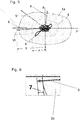
- the detection area 1a which determines whether a product is classified as a good product or a bad product during operation of the device, is determined by the centric extension of the reference area 1 by a factor Y7x the length of the vector 6 Y divided by the extent of the detection area x in the direction of the vector 6. In this way, a detection area of the same shape as the reference area 1 is formed, but which is significantly larger than the reference area, so that considerably more products are classified as good products. In the method according to the invention according to Figures 5 and 6 the size of the detection area 1a is thus automatically determined by the expansion carried out in this way. In this way the detection area would extend to the vector tip.
- the factor obtained is reduced by a safety margin or a safety margin 7 is subtracted from the factor, so that after the centric stretching of the reference area 1, the vector 6 with a safety margin 7 ( Fig. 6 ) protrudes beyond detection area 1a. It can be seen that this is now significantly larger than the previous reference range 1 according to the prior art Fig. 4 . In spite of this, all three test spheres are reliably detected in accordance with vectors 4, 5 and 6. The valid product signal 3 off Fig. 4 , which was incorrectly interpreted as "metal" in the prior art, is now regarded as a good product.
- Fig. 6 shows the safety margin 7, which is adhered to so that the requirements are reliably detected.
- the safety margin is preferably a smaller part of the vector amount 6, for example one fifth to one twentieth of the vector amount 6.
Landscapes
- Engineering & Computer Science (AREA)
- Manufacturing & Machinery (AREA)
- Physics & Mathematics (AREA)
- Life Sciences & Earth Sciences (AREA)
- General Life Sciences & Earth Sciences (AREA)
- General Physics & Mathematics (AREA)
- Geophysics (AREA)
- Geophysics And Detection Of Objects (AREA)
Priority Applications (1)
| Application Number | Priority Date | Filing Date | Title |
|---|---|---|---|
| PL19162141T PL3542914T3 (pl) | 2018-03-20 | 2019-03-12 | Sposób i urządzenie do oddzielania materiałów zawierających metal |
Applications Claiming Priority (2)
| Application Number | Priority Date | Filing Date | Title |
|---|---|---|---|
| DE102018106569 | 2018-03-20 | ||
| DE102018121762.5A DE102018121762A1 (de) | 2018-03-20 | 2018-09-06 | Verfahren und Vorrichtung zur Aussonderung von metallhaltigen Materialien |
Publications (2)
| Publication Number | Publication Date |
|---|---|
| EP3542914A1 EP3542914A1 (de) | 2019-09-25 |
| EP3542914B1 true EP3542914B1 (de) | 2021-06-23 |
Family
ID=65766902
Family Applications (1)
| Application Number | Title | Priority Date | Filing Date |
|---|---|---|---|
| EP19162141.6A Active EP3542914B1 (de) | 2018-03-20 | 2019-03-12 | Verfahren und vorrichtung zur aussonderung von metallhaltigen materialien |
Country Status (3)
| Country | Link |
|---|---|
| EP (1) | EP3542914B1 (pl) |
| ES (1) | ES2887055T3 (pl) |
| PL (1) | PL3542914T3 (pl) |
Families Citing this family (1)
| Publication number | Priority date | Publication date | Assignee | Title |
|---|---|---|---|---|
| CN118884539B (zh) * | 2024-07-26 | 2025-07-22 | 上海太易检测技术股份有限公司 | 一种金属检测机的智能化检测方法和系统 |
Family Cites Families (2)
| Publication number | Priority date | Publication date | Assignee | Title |
|---|---|---|---|---|
| GB0000566D0 (en) * | 2000-01-12 | 2000-03-01 | Willett Int Ltd | Apparatus and method |
| EP2625551B1 (en) * | 2010-10-07 | 2016-11-09 | Mettler-Toledo Safeline Limited | Method for operating a metal detection system and metal detection system |
-
2019
- 2019-03-12 EP EP19162141.6A patent/EP3542914B1/de active Active
- 2019-03-12 PL PL19162141T patent/PL3542914T3/pl unknown
- 2019-03-12 ES ES19162141T patent/ES2887055T3/es active Active
Non-Patent Citations (1)
| Title |
|---|
| None * |
Also Published As
| Publication number | Publication date |
|---|---|
| ES2887055T3 (es) | 2021-12-21 |
| PL3542914T3 (pl) | 2021-12-13 |
| EP3542914A1 (de) | 2019-09-25 |
Similar Documents
| Publication | Publication Date | Title |
|---|---|---|
| EP3455000B1 (de) | Verfahren und vorrichtung für das legierungsabhängige sortieren von metallschrott, insbesondere aluminiumschrott | |
| DE60117958T2 (de) | Vorrichtung und verfahren zum nachweis der verunreinigung eines objektes durch ein metall | |
| DE69908620T2 (de) | Multidimensionales verfahren und system für statistische prozessteuerung | |
| DE68918825T2 (de) | Verfahren und Vorrichtung zur Bestimmung der Beschaffenheit oder einer Eigenschaft eines nichtmetallischen, leitfähigen Materials mit Hilfe eines elektromagnetischen Wechselfeldes. | |
| EP0092094B1 (de) | Verfahren und Vorrichtung zur Prüfung von Werkstoffen nach dem Wirbelstromprinzip | |
| EP1877836B1 (de) | Verfahren und vorrichtung zur kontrolle von handgepäck und anderen mitgeführten gegenständen | |
| EP2375243A1 (de) | Thermografisches Prüfverfahren und Prüfvorrichtung zur Durchführung des Prüfverfahrens | |
| DE102016014381A1 (de) | Spritzgießsystem | |
| EP1194765A1 (de) | Verfahren und vorrichtung zur prozessoptimierenden einstellung von parametern eines produktionsprozesses | |
| DE102016122119A1 (de) | Sortieranlage und Sortierverfahren | |
| DE3850625T2 (de) | System für Feststellung von verstreutem Metall in Waren. | |
| AT523755A2 (de) | Verfahren zum abschnittsweisen Bestimmen der Korngrößenverteilung eines auf ein Förderband aufgegebenen Schüttgutes | |
| EP4459546A1 (de) | Verfahren und vorrichtung zur detektion von anomalien in zweidimensionalen digitalen bildern von produkten | |
| EP3542914A1 (de) | Verfahren und vorrichtung zur aussonderung von metallhaltigen materialien | |
| DE112016001250T5 (de) | Ein Flüssigkeitsstandsmessverfahren und ein Flüssigkeitsstandsmesser sowie eine Werkzeugmaschine ausgestattet mit diesem Flüssigkeitsstandsmesser | |
| DE102014002273A1 (de) | Verfahren zum Untersuchen eines Wertdokuments und Mittel zur Durchführung des Verfahrens | |
| AT523807A1 (de) | Verfahren zur Staubniederhaltung bei Brechern mit Sprüheinrichtungen | |
| WO2016124165A1 (de) | Verfahren und anordnung zur analyse eines stoffstroms | |
| DE68901752T2 (de) | Verfahren und vorrichtung zum messen der geradheit von rohren. | |
| EP3618975B1 (de) | Sortierungsverfahren für aluminiumpakete und sortieranlage | |
| DE102009059092B4 (de) | Verfahren zur Unterscheidung und Identifikation von Werkstücken aus ferromagnetischem Werkstoff mittels zerstörungsfreier Prüfung | |
| EP4083614B1 (de) | Verfahren zum erfassen der detektionsempfindlichkeit eines röntgengeräts | |
| DE102004052302B4 (de) | Verfahren zur Ausgabe von Messwerten und Anzeigeeinrichtung | |
| EP3799580B1 (de) | Verfahren zur gezielten auswahl eines sensors zur sensorbasierten sortierung eines materialgemisches durch simulation der sensorbasierten sortierung des materialgemisches | |
| EP4357820B1 (de) | Verfahren und vorrichtung zur detektion von metallkörpern in prüfobjekten |
Legal Events
| Date | Code | Title | Description |
|---|---|---|---|
| PUAI | Public reference made under article 153(3) epc to a published international application that has entered the european phase |
Free format text: ORIGINAL CODE: 0009012 |
|
| STAA | Information on the status of an ep patent application or granted ep patent |
Free format text: STATUS: THE APPLICATION HAS BEEN PUBLISHED |
|
| AK | Designated contracting states |
Kind code of ref document: A1 Designated state(s): AL AT BE BG CH CY CZ DE DK EE ES FI FR GB GR HR HU IE IS IT LI LT LU LV MC MK MT NL NO PL PT RO RS SE SI SK SM TR |
|
| AX | Request for extension of the european patent |
Extension state: BA ME |
|
| STAA | Information on the status of an ep patent application or granted ep patent |
Free format text: STATUS: REQUEST FOR EXAMINATION WAS MADE |
|
| 17P | Request for examination filed |
Effective date: 20191002 |
|
| RBV | Designated contracting states (corrected) |
Designated state(s): AL AT BE BG CH CY CZ DE DK EE ES FI FR GB GR HR HU IE IS IT LI LT LU LV MC MK MT NL NO PL PT RO RS SE SI SK SM TR |
|
| STAA | Information on the status of an ep patent application or granted ep patent |
Free format text: STATUS: EXAMINATION IS IN PROGRESS |
|
| 17Q | First examination report despatched |
Effective date: 20200504 |
|
| GRAP | Despatch of communication of intention to grant a patent |
Free format text: ORIGINAL CODE: EPIDOSNIGR1 |
|
| STAA | Information on the status of an ep patent application or granted ep patent |
Free format text: STATUS: GRANT OF PATENT IS INTENDED |
|
| INTG | Intention to grant announced |
Effective date: 20210217 |
|
| GRAJ | Information related to disapproval of communication of intention to grant by the applicant or resumption of examination proceedings by the epo deleted |
Free format text: ORIGINAL CODE: EPIDOSDIGR1 |
|
| STAA | Information on the status of an ep patent application or granted ep patent |
Free format text: STATUS: EXAMINATION IS IN PROGRESS |
|
| GRAP | Despatch of communication of intention to grant a patent |
Free format text: ORIGINAL CODE: EPIDOSNIGR1 |
|
| STAA | Information on the status of an ep patent application or granted ep patent |
Free format text: STATUS: GRANT OF PATENT IS INTENDED |
|
| GRAS | Grant fee paid |
Free format text: ORIGINAL CODE: EPIDOSNIGR3 |
|
| INTC | Intention to grant announced (deleted) | ||
| GRAA | (expected) grant |
Free format text: ORIGINAL CODE: 0009210 |
|
| STAA | Information on the status of an ep patent application or granted ep patent |
Free format text: STATUS: THE PATENT HAS BEEN GRANTED |
|
| INTG | Intention to grant announced |
Effective date: 20210428 |
|
| AK | Designated contracting states |
Kind code of ref document: B1 Designated state(s): AL AT BE BG CH CY CZ DE DK EE ES FI FR GB GR HR HU IE IS IT LI LT LU LV MC MK MT NL NO PL PT RO RS SE SI SK SM TR |
|
| REG | Reference to a national code |
Ref country code: GB Ref legal event code: FG4D Free format text: NOT ENGLISH |
|
| REG | Reference to a national code |
Ref country code: CH Ref legal event code: EP |
|
| REG | Reference to a national code |
Ref country code: AT Ref legal event code: REF Ref document number: 1403849 Country of ref document: AT Kind code of ref document: T Effective date: 20210715 Ref country code: DE Ref legal event code: R096 Ref document number: 502019001645 Country of ref document: DE |
|
| REG | Reference to a national code |
Ref country code: IE Ref legal event code: FG4D Free format text: LANGUAGE OF EP DOCUMENT: GERMAN |
|
| REG | Reference to a national code |
Ref country code: NL Ref legal event code: FP |
|
| REG | Reference to a national code |
Ref country code: LT Ref legal event code: MG9D |
|
| PG25 | Lapsed in a contracting state [announced via postgrant information from national office to epo] |
Ref country code: BG Free format text: LAPSE BECAUSE OF FAILURE TO SUBMIT A TRANSLATION OF THE DESCRIPTION OR TO PAY THE FEE WITHIN THE PRESCRIBED TIME-LIMIT Effective date: 20210923 Ref country code: FI Free format text: LAPSE BECAUSE OF FAILURE TO SUBMIT A TRANSLATION OF THE DESCRIPTION OR TO PAY THE FEE WITHIN THE PRESCRIBED TIME-LIMIT Effective date: 20210623 Ref country code: HR Free format text: LAPSE BECAUSE OF FAILURE TO SUBMIT A TRANSLATION OF THE DESCRIPTION OR TO PAY THE FEE WITHIN THE PRESCRIBED TIME-LIMIT Effective date: 20210623 Ref country code: LT Free format text: LAPSE BECAUSE OF FAILURE TO SUBMIT A TRANSLATION OF THE DESCRIPTION OR TO PAY THE FEE WITHIN THE PRESCRIBED TIME-LIMIT Effective date: 20210623 |
|
| PG25 | Lapsed in a contracting state [announced via postgrant information from national office to epo] |
Ref country code: GR Free format text: LAPSE BECAUSE OF FAILURE TO SUBMIT A TRANSLATION OF THE DESCRIPTION OR TO PAY THE FEE WITHIN THE PRESCRIBED TIME-LIMIT Effective date: 20210924 Ref country code: LV Free format text: LAPSE BECAUSE OF FAILURE TO SUBMIT A TRANSLATION OF THE DESCRIPTION OR TO PAY THE FEE WITHIN THE PRESCRIBED TIME-LIMIT Effective date: 20210623 Ref country code: NO Free format text: LAPSE BECAUSE OF FAILURE TO SUBMIT A TRANSLATION OF THE DESCRIPTION OR TO PAY THE FEE WITHIN THE PRESCRIBED TIME-LIMIT Effective date: 20210923 Ref country code: SE Free format text: LAPSE BECAUSE OF FAILURE TO SUBMIT A TRANSLATION OF THE DESCRIPTION OR TO PAY THE FEE WITHIN THE PRESCRIBED TIME-LIMIT Effective date: 20210623 Ref country code: RS Free format text: LAPSE BECAUSE OF FAILURE TO SUBMIT A TRANSLATION OF THE DESCRIPTION OR TO PAY THE FEE WITHIN THE PRESCRIBED TIME-LIMIT Effective date: 20210623 |
|
| REG | Reference to a national code |
Ref country code: ES Ref legal event code: FG2A Ref document number: 2887055 Country of ref document: ES Kind code of ref document: T3 Effective date: 20211221 |
|
| PG25 | Lapsed in a contracting state [announced via postgrant information from national office to epo] |
Ref country code: CZ Free format text: LAPSE BECAUSE OF FAILURE TO SUBMIT A TRANSLATION OF THE DESCRIPTION OR TO PAY THE FEE WITHIN THE PRESCRIBED TIME-LIMIT Effective date: 20210623 Ref country code: SM Free format text: LAPSE BECAUSE OF FAILURE TO SUBMIT A TRANSLATION OF THE DESCRIPTION OR TO PAY THE FEE WITHIN THE PRESCRIBED TIME-LIMIT Effective date: 20210623 Ref country code: PT Free format text: LAPSE BECAUSE OF FAILURE TO SUBMIT A TRANSLATION OF THE DESCRIPTION OR TO PAY THE FEE WITHIN THE PRESCRIBED TIME-LIMIT Effective date: 20211025 Ref country code: RO Free format text: LAPSE BECAUSE OF FAILURE TO SUBMIT A TRANSLATION OF THE DESCRIPTION OR TO PAY THE FEE WITHIN THE PRESCRIBED TIME-LIMIT Effective date: 20210623 Ref country code: EE Free format text: LAPSE BECAUSE OF FAILURE TO SUBMIT A TRANSLATION OF THE DESCRIPTION OR TO PAY THE FEE WITHIN THE PRESCRIBED TIME-LIMIT Effective date: 20210623 Ref country code: SK Free format text: LAPSE BECAUSE OF FAILURE TO SUBMIT A TRANSLATION OF THE DESCRIPTION OR TO PAY THE FEE WITHIN THE PRESCRIBED TIME-LIMIT Effective date: 20210623 |
|
| REG | Reference to a national code |
Ref country code: DE Ref legal event code: R097 Ref document number: 502019001645 Country of ref document: DE |
|
| PG25 | Lapsed in a contracting state [announced via postgrant information from national office to epo] |
Ref country code: DK Free format text: LAPSE BECAUSE OF FAILURE TO SUBMIT A TRANSLATION OF THE DESCRIPTION OR TO PAY THE FEE WITHIN THE PRESCRIBED TIME-LIMIT Effective date: 20210623 |
|
| PLBE | No opposition filed within time limit |
Free format text: ORIGINAL CODE: 0009261 |
|
| STAA | Information on the status of an ep patent application or granted ep patent |
Free format text: STATUS: NO OPPOSITION FILED WITHIN TIME LIMIT |
|
| 26N | No opposition filed |
Effective date: 20220324 |
|
| PG25 | Lapsed in a contracting state [announced via postgrant information from national office to epo] |
Ref country code: AL Free format text: LAPSE BECAUSE OF FAILURE TO SUBMIT A TRANSLATION OF THE DESCRIPTION OR TO PAY THE FEE WITHIN THE PRESCRIBED TIME-LIMIT Effective date: 20210623 |
|
| PG25 | Lapsed in a contracting state [announced via postgrant information from national office to epo] |
Ref country code: MC Free format text: LAPSE BECAUSE OF FAILURE TO SUBMIT A TRANSLATION OF THE DESCRIPTION OR TO PAY THE FEE WITHIN THE PRESCRIBED TIME-LIMIT Effective date: 20210623 |
|
| PG25 | Lapsed in a contracting state [announced via postgrant information from national office to epo] |
Ref country code: LU Free format text: LAPSE BECAUSE OF NON-PAYMENT OF DUE FEES Effective date: 20220312 Ref country code: IE Free format text: LAPSE BECAUSE OF NON-PAYMENT OF DUE FEES Effective date: 20220312 |
|
| PGFP | Annual fee paid to national office [announced via postgrant information from national office to epo] |
Ref country code: PL Payment date: 20230306 Year of fee payment: 5 Ref country code: BE Payment date: 20230321 Year of fee payment: 5 |
|
| P01 | Opt-out of the competence of the unified patent court (upc) registered |
Effective date: 20230510 |
|
| PGFP | Annual fee paid to national office [announced via postgrant information from national office to epo] |
Ref country code: NL Payment date: 20230321 Year of fee payment: 5 |
|
| PGFP | Annual fee paid to national office [announced via postgrant information from national office to epo] |
Ref country code: CH Payment date: 20230401 Year of fee payment: 5 |
|
| PG25 | Lapsed in a contracting state [announced via postgrant information from national office to epo] |
Ref country code: MK Free format text: LAPSE BECAUSE OF FAILURE TO SUBMIT A TRANSLATION OF THE DESCRIPTION OR TO PAY THE FEE WITHIN THE PRESCRIBED TIME-LIMIT Effective date: 20210623 Ref country code: CY Free format text: LAPSE BECAUSE OF FAILURE TO SUBMIT A TRANSLATION OF THE DESCRIPTION OR TO PAY THE FEE WITHIN THE PRESCRIBED TIME-LIMIT Effective date: 20210623 |
|
| PG25 | Lapsed in a contracting state [announced via postgrant information from national office to epo] |
Ref country code: HU Free format text: LAPSE BECAUSE OF FAILURE TO SUBMIT A TRANSLATION OF THE DESCRIPTION OR TO PAY THE FEE WITHIN THE PRESCRIBED TIME-LIMIT; INVALID AB INITIO Effective date: 20190312 |
|
| PG25 | Lapsed in a contracting state [announced via postgrant information from national office to epo] |
Ref country code: MT Free format text: LAPSE BECAUSE OF FAILURE TO SUBMIT A TRANSLATION OF THE DESCRIPTION OR TO PAY THE FEE WITHIN THE PRESCRIBED TIME-LIMIT Effective date: 20210623 |
|
| REG | Reference to a national code |
Ref country code: CH Ref legal event code: PL |
|
| REG | Reference to a national code |
Ref country code: NL Ref legal event code: MM Effective date: 20240401 |
|
| PG25 | Lapsed in a contracting state [announced via postgrant information from national office to epo] |
Ref country code: NL Free format text: LAPSE BECAUSE OF NON-PAYMENT OF DUE FEES Effective date: 20240401 |
|
| REG | Reference to a national code |
Ref country code: BE Ref legal event code: MM Effective date: 20240331 |
|
| PG25 | Lapsed in a contracting state [announced via postgrant information from national office to epo] |
Ref country code: NL Free format text: LAPSE BECAUSE OF NON-PAYMENT OF DUE FEES Effective date: 20240401 |
|
| PG25 | Lapsed in a contracting state [announced via postgrant information from national office to epo] |
Ref country code: BE Free format text: LAPSE BECAUSE OF NON-PAYMENT OF DUE FEES Effective date: 20240331 |
|
| PG25 | Lapsed in a contracting state [announced via postgrant information from national office to epo] |
Ref country code: BE Free format text: LAPSE BECAUSE OF NON-PAYMENT OF DUE FEES Effective date: 20240331 Ref country code: CH Free format text: LAPSE BECAUSE OF NON-PAYMENT OF DUE FEES Effective date: 20240331 |
|
| PGFP | Annual fee paid to national office [announced via postgrant information from national office to epo] |
Ref country code: DE Payment date: 20250325 Year of fee payment: 7 |
|
| REG | Reference to a national code |
Ref country code: AT Ref legal event code: MM01 Ref document number: 1403849 Country of ref document: AT Kind code of ref document: T Effective date: 20240312 |
|
| PGFP | Annual fee paid to national office [announced via postgrant information from national office to epo] |
Ref country code: ES Payment date: 20250429 Year of fee payment: 7 |
|
| PG25 | Lapsed in a contracting state [announced via postgrant information from national office to epo] |
Ref country code: AT Free format text: LAPSE BECAUSE OF NON-PAYMENT OF DUE FEES Effective date: 20240312 |
|
| PG25 | Lapsed in a contracting state [announced via postgrant information from national office to epo] |
Ref country code: PL Free format text: LAPSE BECAUSE OF NON-PAYMENT OF DUE FEES Effective date: 20240312 |
|
| PG25 | Lapsed in a contracting state [announced via postgrant information from national office to epo] |
Ref country code: TR Free format text: LAPSE BECAUSE OF FAILURE TO SUBMIT A TRANSLATION OF THE DESCRIPTION OR TO PAY THE FEE WITHIN THE PRESCRIBED TIME-LIMIT Effective date: 20210623 |
|
| PGFP | Annual fee paid to national office [announced via postgrant information from national office to epo] |
Ref country code: GB Payment date: 20260324 Year of fee payment: 8 |
|
| PGFP | Annual fee paid to national office [announced via postgrant information from national office to epo] |
Ref country code: AT Payment date: 20260410 Year of fee payment: 5 |
|
| PGFP | Annual fee paid to national office [announced via postgrant information from national office to epo] |
Ref country code: IT Payment date: 20260324 Year of fee payment: 8 |
|
| PGFP | Annual fee paid to national office [announced via postgrant information from national office to epo] |
Ref country code: FR Payment date: 20260320 Year of fee payment: 8 |