EP3541733B1 - Rewinder for the production of paper logs - Google Patents
Rewinder for the production of paper logs Download PDFInfo
- Publication number
- EP3541733B1 EP3541733B1 EP17829334.6A EP17829334A EP3541733B1 EP 3541733 B1 EP3541733 B1 EP 3541733B1 EP 17829334 A EP17829334 A EP 17829334A EP 3541733 B1 EP3541733 B1 EP 3541733B1
- Authority
- EP
- European Patent Office
- Prior art keywords
- dragging
- web
- rewinder
- paper
- rewinder according
- Prior art date
- Legal status (The legal status is an assumption and is not a legal conclusion. Google has not performed a legal analysis and makes no representation as to the accuracy of the status listed.)
- Active
Links
- 238000004519 manufacturing process Methods 0.000 title claims description 18
- 238000004804 winding Methods 0.000 claims description 32
- 230000007246 mechanism Effects 0.000 claims description 12
- 238000005520 cutting process Methods 0.000 description 17
- 238000000034 method Methods 0.000 description 10
- 239000003292 glue Substances 0.000 description 7
- 230000008569 process Effects 0.000 description 7
- 238000011144 upstream manufacturing Methods 0.000 description 5
- 238000004026 adhesive bonding Methods 0.000 description 4
- 230000008901 benefit Effects 0.000 description 4
- 230000015572 biosynthetic process Effects 0.000 description 4
- 230000003287 optical effect Effects 0.000 description 2
- 230000009471 action Effects 0.000 description 1
- 230000009849 deactivation Effects 0.000 description 1
- 230000001419 dependent effect Effects 0.000 description 1
- 238000001514 detection method Methods 0.000 description 1
- 230000003292 diminished effect Effects 0.000 description 1
- 239000013013 elastic material Substances 0.000 description 1
- 125000000524 functional group Chemical group 0.000 description 1
- 230000002265 prevention Effects 0.000 description 1
- 238000010561 standard procedure Methods 0.000 description 1
Images


Classifications
-
- B—PERFORMING OPERATIONS; TRANSPORTING
- B65—CONVEYING; PACKING; STORING; HANDLING THIN OR FILAMENTARY MATERIAL
- B65H—HANDLING THIN OR FILAMENTARY MATERIAL, e.g. SHEETS, WEBS, CABLES
- B65H19/00—Changing the web roll
- B65H19/22—Changing the web roll in winding mechanisms or in connection with winding operations
- B65H19/28—Attaching the leading end of the web to the replacement web-roll core or spindle
- B65H19/283—Attaching the leading end of the web to the replacement web-roll core or spindle by applying adhesive to the core
-
- B—PERFORMING OPERATIONS; TRANSPORTING
- B65—CONVEYING; PACKING; STORING; HANDLING THIN OR FILAMENTARY MATERIAL
- B65H—HANDLING THIN OR FILAMENTARY MATERIAL, e.g. SHEETS, WEBS, CABLES
- B65H19/00—Changing the web roll
- B65H19/22—Changing the web roll in winding mechanisms or in connection with winding operations
- B65H19/2238—The web roll being driven by a winding mechanism of the nip or tangential drive type
- B65H19/2269—Cradle
-
- B—PERFORMING OPERATIONS; TRANSPORTING
- B65—CONVEYING; PACKING; STORING; HANDLING THIN OR FILAMENTARY MATERIAL
- B65H—HANDLING THIN OR FILAMENTARY MATERIAL, e.g. SHEETS, WEBS, CABLES
- B65H19/00—Changing the web roll
- B65H19/22—Changing the web roll in winding mechanisms or in connection with winding operations
-
- B—PERFORMING OPERATIONS; TRANSPORTING
- B65—CONVEYING; PACKING; STORING; HANDLING THIN OR FILAMENTARY MATERIAL
- B65H—HANDLING THIN OR FILAMENTARY MATERIAL, e.g. SHEETS, WEBS, CABLES
- B65H20/00—Advancing webs
- B65H20/16—Advancing webs by web-gripping means, e.g. grippers, clips
-
- B—PERFORMING OPERATIONS; TRANSPORTING
- B65—CONVEYING; PACKING; STORING; HANDLING THIN OR FILAMENTARY MATERIAL
- B65H—HANDLING THIN OR FILAMENTARY MATERIAL, e.g. SHEETS, WEBS, CABLES
- B65H2301/00—Handling processes for sheets or webs
- B65H2301/40—Type of handling process
- B65H2301/41—Winding, unwinding
- B65H2301/417—Handling or changing web rolls
- B65H2301/4187—Relative movement of core or web roll in respect of mandrel
- B65H2301/4189—Cutting
-
- B—PERFORMING OPERATIONS; TRANSPORTING
- B65—CONVEYING; PACKING; STORING; HANDLING THIN OR FILAMENTARY MATERIAL
- B65H—HANDLING THIN OR FILAMENTARY MATERIAL, e.g. SHEETS, WEBS, CABLES
- B65H2301/00—Handling processes for sheets or webs
- B65H2301/50—Auxiliary process performed during handling process
- B65H2301/52—Auxiliary process performed during handling process for starting
- B65H2301/522—Threading web into machine
-
- B—PERFORMING OPERATIONS; TRANSPORTING
- B65—CONVEYING; PACKING; STORING; HANDLING THIN OR FILAMENTARY MATERIAL
- B65H—HANDLING THIN OR FILAMENTARY MATERIAL, e.g. SHEETS, WEBS, CABLES
- B65H2404/00—Parts for transporting or guiding the handled material
- B65H2404/10—Rollers
- B65H2404/14—Roller pairs
-
- B—PERFORMING OPERATIONS; TRANSPORTING
- B65—CONVEYING; PACKING; STORING; HANDLING THIN OR FILAMENTARY MATERIAL
- B65H—HANDLING THIN OR FILAMENTARY MATERIAL, e.g. SHEETS, WEBS, CABLES
- B65H2408/00—Specific machines
- B65H2408/20—Specific machines for handling web(s)
- B65H2408/23—Winding machines
- B65H2408/235—Cradles
Landscapes
- Replacement Of Web Rolls (AREA)
Description
- The present invention relates to a rewinder for the production of paper logs.
- It is known that the production of paper logs, from which, for example, are obtained toilet paper rolls or kitchen paper rolls, implies feeding a paper web, consisting of one or more superimposed plies, along a predetermined path where several operations are performed prior to make the logs, including a transverse web incision to form pre-cutting lines that divide the web into separable tear-off sheets. The formation of logs involves the use of cardboard tubes, commonly known as "cores" on whose surface it is distributed a predetermined amount of glue to allow the bonding of the paper web onto the cores introduced into the log-forming machine that is commonly called "rewinder". The glue is distributed on the cores when they pass along a corresponding path comprising an end commonly called "cradle" due its concave conformation. The formation of the logs also implies the use of winding rollers placed in correspondence of the cradle, which determine the rotation of each core about its longitudinal axis thereby causing the winding of the web on the same core. One of said rollers is positioned lower than the cradle while other rollers are placed above the cradle. The process ends when a predetermined number of sheets is wrapped around the core and a portion of the last sheet is glued to the underlying sheet of the same roll (so-called "flap closure" operation). Upon reaching the predetermined number of sheets wrapped around the core, the last sheet of the almost completed log is separated from the first sheet of the next log, for example by means of a compressed air jet directed towards a corresponding pre-cutting line. At this point, the log is discharged from the rewinder.
EP1700805 discloses a rewinder that operates according to the operating scheme disclosed above.US2013/068874 discloses a rewinder for the production of paper logs according to the preamble of claim 1. - At a preliminary stage of the process, the paper web, fed by reels placed on respective unwinders, is carried in substantially manual mode up to the rewinder station that houses the winding rollers. In practice, an operator engages a flap of the paper web at a dragging belt that follows a path provided at a side of the path that will be followed by the web during the production of the logs. Subsequently, the operator, by operating the system in jog mode, from the inside of the rewinder, ensures that the paper web passes between the guide roller, the pre-cutting roller and the winding rollers of the rewinder. Once this step has been completed, the operator cuts the web flap attached to the dragging belt with a knife and removes the excess paper leaving the web in a non-tensioned state. At this point, the operator exits the rewinder and starts the logs production in the automatic mode.
- However, at least the first log must be discarded because the rewinder is started with the paper web in a non-tensioned state. In addition, the procedure described above is inherently risky because the access of the operator inside the rewinder involves the deactivation of several accident prevention systems. In addition, there is the fact that the operators involved in this procedure must be adequately trained for relatively long periods of time.
- The main purpose of the present invention is to eliminate, or at least reduce, the aforesaid drawbacks. This result has been achieved in accordance with the present invention by providing a rewinder having the features indicated in claim 1. Other features of the present invention are the subject of the dependent claims. Thanks to the present invention, it is possible to reduce the risks connected with the paper web threading, to the benefit of operators safety. In addition, it is possible to reduce the scraps when the rewinder is started. It is also possible to automate almost the entire threading operation, which therefore does not necessarily have to be entrusted to highly skilled and trained personnel. Further advantages derive from the relative constructive and functional simplicity of the threading mechanism provided by a rewinder according to the present invention, which also allows to reduce the threading time and from the fact that the existing rewinders can be modified with relative simplicity to make them conform to the invention as the very logs formation cycle is not changed compared to the standard procedures.
- These and further advantages and features of the present invention will be more and better understood thanks to the following description and the accompanying drawings, provided by way of example but not to be considered in a limitative sense, in which:
- ▪
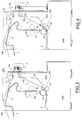
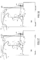
Fig. 1 schematically shows the basic functional groups of a rewinder (RW) according to the present invention, some of which are not shown in the other drawings for simplification; - ▪
Figures 2 to 6 represent a sequence of operative phases implemented by the machine ofFig. 1 , some detail of the machine being omitted to better illustrate others; - ▪
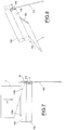
Figures 7 to 10 schematically represent some components of the threading mechanism at different stages of the threading process; - ▪
Fig. 11 is an enlarged detail ofFig. 1 ; - ▪
Fig. 12 is a schematic plan view of the detail ofFig. 11 with some portions removed to better highlight others; - •
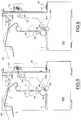
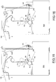
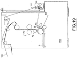
Figures 13 to 19 are views similar to those ofFigs. 1-6 but they show a different configuration of a rewinder according to the present invention; - ▪
Figures 20 to 23 are views similar to those ofFigs. 7-10 but they show a different configuration of the threading mechanism at different stages of the threading process. - Reduced to its essential structure and with reference to the enclosed drawings, a rewinder (RW) according to the present invention is of the type comprising:
- ▪ a cores feeding station (F) for feeding the cores (1) coming from an accumulator (S), in which a rotary feeder (not shown in the drawings) is arranged for engaging a core (1) at a time and introducing it into a guide where a glueing device (GD) is arranged and acting as further disclosed below;
- ▪ means for feeding and transversely pre-cutting a paper web (2) formed of one or more superimposed paper plies, with a set of guide rolls (R1, R2, R3) and pre-cutting rolls (RC) arranged along a predetermined web (2) feeding and pre-cutting path;
- ▪ means for wrapping, or winding, the paper web (2) on a core (1) in a winding station (W) with a first winding roller (R4) located downstream of said guide and pre-cutting rollers (R1, R2, R3, RC), and two additional winding rollers (R5, R6) arranged downstream of the first winding roller (R4) with respect to the direction followed by the cores (1) and the paper web: the second and the third winding roll (R5, R6) being arranged downstream of a curved guide (3) that, in cooperation with the first winding roller (R4), delimits a cradle-shaped channel (CH) downstream of the glueing device (GD), said channel being sequentially crossed by the cores (1) on which the glueing device (GD) distributes a predetermined amount of glue.
- The first winding roller (R4) also has the function of guiding the paper web (2) coming from the guide and pre-cutting rollers positioned upstream.
- The second roller (R5) is below the third roller (R6) of the winding station (W).
- The third winding roller (R6) is mounted on the end of an arm (B6) connected to a respective actuator allowing it to approach, and respectively to move it away from, said channel in relation to the instantaneous diameter of the log being formed.
- In said winding station (W) there is a chute (SW) on which the completed logs, once released by the roller (R6), can roll.
- The system formed by the winding rollers (R4, R5, R6), the respective actuators and related control units are known. Also known are the way of removing a completed log (RO) from the winding station (W) and how to start the formation of a new log in the same station (W). The channel (CH) delimits the last part of the path followed by the paper web (2) and the cores (1) before entering the winding station (W).
- On each core (1) is applied a predetermined amount glue allowing the web (2) to adhere to the same cores (1), according to a process known per se, while the cores (1) advance along a predetermined advancing direction (A), defined by the guide served by the cores feeder, to reach the winding station (W) where the logs are formed. For example, said guide is formed by a set motorized belts (5) driven by pulleys (50) whose axis is horizontal and orthogonal to said advancing direction (A), and a corresponding set of overlying fixed plates (4) having a prevailing longitudinal development (length higher than thickness and height). The motorized belts (5) engage the cores (1) coming from the feeding station (F), obliging them to rotate and advance upstream of the channel (CH). The glueing device (GD) comprises two sets of dispensers (6) placed one after the other between the plates (4). The dispensers (6) distribute the glue, from the above, on the cores (1) along the path imposed by said guide (4, 5). Therefore, on each of the cores (1) passing through the guide (4, 5), it is applied a given amount of glue on two separate points, that serve for bonding the last sheet of a log formed in the station winding (W) with the underlying sheet of the same log and respectively for the adhesion of the first sheet of a new log to a corresponding core (1). Such a process of applying glue to the cores (1) is in itself known.
- Furthermore, the rewinder is provided with a threading mechanism for threading the paper web (2) at a preliminary stage of the paper logs production process.
- In accordance with the present invention, said threading mechanism comprises a dragging belt (100) arranged along a predetermined path on a side of the rewinder (RW), i.e. on a right or left side of the assembly formed by said guide, pre-cutting and winding rollers so as not to interfere with the latter. This path is a closed loop path passing through a paper web feed station arranged upstream of the rewinder (RW) and a dragging unit (101) arranged downstream of the winding station (W). The dragging unit (101) comprises two counter-rotating press rollers (102, 103) with parallel and superimposed axes provided downstream of the winding station (W). A blade (104) is disposed and acting on a side downstream of the press rolls (102, 103) for cutting the flap (2L) of the web (2) engaged to the dragging belt (100) during the preliminary stage of the paper logs production process.
- As further disclosed below, the threading mechanism is configured to obtain a tensioning of the paper web (2) after the cut of the flap (2L) by means of the blade (104). According to the example shown in the accompanying drawings, the press rollers (102, 103) of the threading unit (101) are arranged with their respective longitudinal axes parallel to the axes of the guide, pre-cutting and winding rollers, i.e. are oriented transversely to the paper web (2).
- The upper press roller (102) is an idle roller, while the lower press roller (103) is motorized. In addition, the upper roller (102) is mounted on a support (105) allowing to adjusts the pressure exerted by the upper roller on the lower roller (103) by means of a lever (106) controlled by a control screw (107) acting on the same lever (106) that serves as a connecting member between the adjusting screw and the upper roll support. The adjusting screw (107) can be electrically actuated by means of a respective actuator (108). The lower press roller (103) is secured to a fixed part (FR) of the rewinder (RW) at each of its ends by means of a connecting flange (109) in which a respective end of the roller (103) is inserted with the interposition of a bearing (110). At its end (right end in the example shown in
Fig. 12 ), the lower roller (103) has a groove in which the dragging belt (100) is guided. Said groove is defined by a pulley (111) mounted on said end of the roller (103) through a corresponding bearing (112). The blade (104) is preferably a fixed blade mounted on an arm (113) that is also fixed to the fixed structure (FR) of the rewinder (RW). The arm (113) and the blade (104) are positioned downstream of the pulley (112) with respect to the direction followed by the flap (2L) engaged to the dragging belt (100). Furthermore, the blade (104) is positioned at a predetermined distance (D) from the fixed structure (FR) greater than the distance (d) of the pulley groove (112) from the same structure (FR). In other words, the blade (104) is more distant from the structure (FR) than the pulley groove (112) where the dragging belt(100) is guided. Therefore, when the flap (2L) attached to the dragging belt (100) passes through the dragging unit (101), since the belt (100) is to the side of the blade (104) (to the right ofblade 104 in the example) the latter acts on the web (2) by cutting the flap (2L) so that the web (2) is released from the dragging belt and the production of the logs can be started as further described below. The steps now described are also shown inFigures 7-10 . In particular,Fig. 7 shows the flap (2L) of the web (2) still hooked to the dragging belt(100). InFig.8 the flap (2L) is not visible since this is a perspective view.Fig. 9 and Fig. 10 show the flap (2L) hooked to the belt (100) and cut by the blade (104). InFig. 10 , the web (2) is released from the belt (100). InFig. 7-10 , the arrow "F2" indicates the direction from which the web (2) comes. Then, the dragging unit (101) is configured to operate both the threading of the belt (2) and the cutting of the flap (2L) of the latter hooked to the belt (100). InFig.2 , the web (2) is not shown because it has not yet been conveyed to the rewinder (RW). However, the dragging belt (100) is represented, whose forward part (part moving towards the unit 101) follows a path parallel to that which will be subsequently followed by the web (2) as mentioned above. Since inFigure 2 the rewinder (RW) is represented in side view, said paths appear to be coincident but actually they are not exactly coincident. The return part of the bumper threading (100), that is, the part of the dragging belt moving toward the unwinders arranged in the web feed station (FW), is developed along a path different from the path followed by said forward part. InFig. 1 , the path of the web (2) and the path of the forward part of the belt (100) is represented by dashed lines, while the belt (100) return part is represented by a continuous line. The "100R" arrows indicate the movement of the belt (100) return part. - In
Fig.2 the arrows "100A" and "100R" respectively show the movement of the forward part and the movement of the return part of the dragging belt (100). - Starting from the condition shown in
Fig. 2 , the operator, after having hooked the flap (2L) to the belt (100) upstream of the rewinder (RW), starts the threading step: while the machine (RW) and the pre-cutting rollers (RC) are activated, the belt (100) drags the web (2) along the predetermined path through the rollers (R1, R2, R3, RC, R4, R5, R6) up to the press rollers (102, 103); at the end of this phase, the web (2) is in the configuration shown inFig. 3 and passes on a further roller (RT) equipped with a load cell, the function of which is disclosed below, placed at an intermediate position between the winding station (W) and dragging unit (101). In particular, it is noted that the web (2) has passed through the rollers (102,103) so that the flap (2L) has been cut by the blade (104) as disclosed above. Therefore, the web (2) is released from the dragging belt (100). The rollers (102, 103) continue to drag the web (2) until the load cell of roller (RT) detects a predetermined value indicative of a correct web tensioning (Fig. 4 ). At this point, a core (1) is introduced into the guide (4, 5). When the core (1) reaches the winding station (W), it is commanded the tear of the web (2) along a pre-cutting line thereof downstream of the winding station (W), where the production of the first log starts (Fig.5 ). In practice, the threading thus operated is an initial stage in the production of logs. For example, said web (2) tearing is obtained by delivering a compressed air jet to the selected pre-cutting line as described inUS9079738 Fig.5 , the tail of the web (2) downstream of the station (W) is indicated by the reference "2T". The rollers (102, 103) continue to rotate until the tail (2T) of the ribbon (2) is released from the rewinder (RW). Excess paper (2E), i.e. the part of the paper web (2) that has been separated from the one that winds on the cores to produce the logs, accumulates out of the rewinder and is taken away by the operator (Fig.6 ). - In
Figures 3 to 6 , the web (2) is represented by a line thicker than the other lines to better highlight it. As shown inFig.11 , downstream of each of the pressure rollers (102, 103) of the unit (101) is positioned a corresponding doctor blade (114, 115) which prevents the web (2) from being rewound on the same rollers. For example, the dragging belt (100) is of the type described inEP2909120B1 . - The tension of the paper web can also be controlled by means of a torque limiting clutch on the motorized roller (103) of the drive unit.
- From the foregoing description it is evident that the dangerousness of the paper web threading is diminished to the benefit of the operators safety; that it is possible to reduce the wastes when the rewinder is started, since the first log is already produced with the paper properly tensioned; that the threading operation can be easily automated and therefore it does not have to be necessarily entrusted to highly skilled and trained personnel; that the threading mechanism provided with a rewinder according to the present invention is structurally and functionally simple and also allows to reduce the time required to execute the threading; and that existing rewinders can be modified with relative simplicity to make them conform to the invention as the very logs production cycle is not changed compared to conventional procedures.
- In the example shown in
Figs. 1-6 , the dragging belt (100) has a part (100X) downstream of the roller (R6), i.e. to the right of the roller (R6) in the drawings. In the example shown inFigs. 13-19 , said part (100X) of the dragging belt (100) is upstream of the roller (R6), i.e. to the left of the roller (R6) in the drawings. In the configuration ofFigs. 13-19 the roller (R6), which is a motorized roller, can be used to assist the action of the belt (100). In fact, during the threading step (step in which the roller R6 is not used for logs production) the roller (R6) can be rotated in a direction assisting the threading of the paper web (2): with reference to the drawings, the roller (R6) can be rotated clockwise and, when the threading of the paper web is completed, that is, when the production of the logs begins, the roller (R6) can be rotated counterclockwise (i.e. in the direction that produces the winding of thepaper web 2 on the cores 1). By adopting this configuration for the belt (100), the dragging (101) may be arranged at a lower height than in the case exemplified inFigs.1-6 . - In accordance with the example shown in
Figs. 20-23 , two dragging belts (100) are provided which move on two parallel paths along the two sides of the rewinder. The use of two dragging belts may allow two flaps (2L) of the paper web (2) to engage the threading mechanism, i.e. to hook one flap (2L) to a belt (100) and another flap (2L) to another belt (100). In this case, as shown inFigs. 20-23 , two blades (104), i.e. a blade (104) for each side of the roller (103), are provided. Each of the two blades (104) in this example cuts the corresponding flap (2L) of the paper web (2). - More in general, a rewinder for the production of paper logs according to the present invention comprises:
- means (R1, R2, R3, RC) adapted to guide and transversely pre-cut a paper web (2) along a predetermined path,
- means (R4, R5, R6) adapted to wind a predetermined amount of the paper web (2) on a core (1) in a winding station (W), and
a threading mechanism for threading the web (2) along said path, wherein - the threading mechanism comprises a dragging unit (101) provided with dragging means (102, 103) adapted to engage the web (2) to drag it along said path with a predetermined feed direction (F2) and at least one dragging member (100) adapted to engage a respective flap (2L) of the web (2) in a dragging step preceding the production of the logs, and
- said dragging unit (101) is located downstream of said winding station (W) with respect to said feed direction (F2) of the paper web (2) and is provided with release means (104) adapted to release said flap (2L) of the web (2) from the dragging member, the release means (104) being arranged downstream of the dragging means (102, 103) so as to intercept the flap (2L) of the web (2) and disengage it from the dragging member (100) while the web (2) is fed along said direction (F2) by the dragging means (102, 103).
- According to the examples disclosed above, the dragging member is a flexible dragging member. In particular, the dragging member can be a dragging belt of the type previously indicated.
- Furthermore, in accordance with the examples previously disclosed, the at least one dragging member (100) is arranged laterally to the dragging means (102, 103). According to the examples disclosed above, the release means for releasing the paper web (2) from the dragging means comprise one or more blades (104).
- According to the examples disclosed above, the dragging means are constituted by rollers (102,103) forming a nip crossed by the web (2) in the threading step. The pressure in the nip is adjustable. One of the rollers (102, 103) can be coated with an elastic material, such as rubber, limiting its traction capacity in relation to the pressure in the nip.
- According to the examples disclosed above, the tensioning of the paper web can be controlled by electronic or mechanical control means.
- The paper web tensioning step can also be started in accordance with the detection performed by means, for example optical means comprising photocells (116a, 116b) suitably provided close to the dragging unit (101), which detect the complete passage of the web (2) through the same unit (101). With reference to the example schematically shown in
Figures 7 and9 , in which the photocells (116a, 116b) are located above the dragging unit, when the web (2) is in the position ofFig. 7 only one photocell (116b) reads its presence, while when the web (2) is in the position ofFig.9 , both photocells (116a, 116b) detect the presence of the web (2). This latter condition corresponds to the transit of both the side edges of the web (2) through the dragging unit and then a programmable control unit (not visible in the drawings) which receives and processes the signals of the optical means (116a, 116b), activates said tensioning step. In practice, execution details may however vary in an equivalent manner to the individual elements described and illustrated without departing from the scope of the claims.
Claims (11)
- Rewinder for the production of paper logs, comprising means (R1, R2, R3, RC) adapted to guide and transversely pre-cut a paper web (2) along a predetermined path, means (R4, R5, R6) adapted to wind a predetermined amount of the paper web (2) on a core (1) in a winding station(W), and a threading mechanism for threading the web (2) along said path, characterized in that the threading mechanism comprises a dragging unit (101) provided with dragging means (102, 103) adapted to engage the web (2) to drag it along said path with a predetermined feed direction (F2) and at least one dragging member (100) adapted to engage a respective flap (2L) of the web (2) in a dragging step preceding the production of the logs, and said dragging unit (101) is located downstream of said winding station (W) with respect to said feed direction (F2) of the paper web (2) and is provided with release means (104) adapted to release said flap (2L) of the web (2) from the dragging member, the release means (104) being arranged downstream of the dragging means (102, 103) so as to intercept the flap (2L) of the web (2) and disengage it from the dragging member (100) while the web (2) is fed along said direction (F2) by the dragging means (102, 103).
- Rewinder according to claim 1 characterized in that the at least one dragging member (100) is a flexible member.
- Rewinder according to claim 1 characterized in that the at least one dragging member (100) is a dragging belt.
- Rewinder according to claim 1 characterized in that said at least one dragging member (100) is arranged laterally to the dragging means (102, 103).
- Rewinder according to claim 1 characterized in that the release means for releasing the paper web (2) from the dragging means comprise one or more blades (104).
- Rewinder according to claim 1 characterized in that said dragging means are constituted by rollers (102,103) forming a nip crossed by the web (2) in the threading step
- Rewinder according to claim 6, it characterized in that the pressure in the nip is adjustable.
- Rewinder according to claim 1 characterized in that it comprises means adapted to control the tensioning of the web (2) subsequent to said dragging step.
- Rewinder according to claim 8 characterized in that the means controlling the tensioning of the web (2) are electronic control means.
- Rewinder according to claim 8 characterized in that the means controlling the tensioning of the web (2) are mechanical control means.
- Rewinder according to claim 1 characterized in that the dragging unit comprises means (116a, 116b) adapted to detect the presence of both the side edges of the web (2).
Priority Applications (1)
| Application Number | Priority Date | Filing Date | Title |
|---|---|---|---|
| RS20201180A RS60904B1 (en) | 2016-11-21 | 2017-10-30 | Rewinder for the production of paper logs |
Applications Claiming Priority (2)
| Application Number | Priority Date | Filing Date | Title |
|---|---|---|---|
| IT102016000117182A IT201600117182A1 (en) | 2016-11-21 | 2016-11-21 | Rewinder. |
| PCT/IT2017/000236 WO2018092167A1 (en) | 2016-11-21 | 2017-10-30 | Rewinder for the production of paper logs |
Publications (2)
| Publication Number | Publication Date |
|---|---|
| EP3541733A1 EP3541733A1 (en) | 2019-09-25 |
| EP3541733B1 true EP3541733B1 (en) | 2020-09-09 |
Family
ID=58266129
Family Applications (1)
| Application Number | Title | Priority Date | Filing Date |
|---|---|---|---|
| EP17829334.6A Active EP3541733B1 (en) | 2016-11-21 | 2017-10-30 | Rewinder for the production of paper logs |
Country Status (10)
| Country | Link |
|---|---|
| US (1) | US11091340B2 (en) |
| EP (1) | EP3541733B1 (en) |
| JP (1) | JP6952774B2 (en) |
| CN (1) | CN110114291B (en) |
| BR (1) | BR112019004801B1 (en) |
| ES (1) | ES2821881T3 (en) |
| IT (1) | IT201600117182A1 (en) |
| RS (1) | RS60904B1 (en) |
| RU (1) | RU2737318C1 (en) |
| WO (1) | WO2018092167A1 (en) |
Families Citing this family (5)
| Publication number | Priority date | Publication date | Assignee | Title |
|---|---|---|---|---|
| US11208282B2 (en) * | 2018-12-06 | 2021-12-28 | Paper Converting Machine Company | Method of initiating a web winding process in a web winding system |
| IT201900001069A1 (en) | 2019-01-24 | 2020-07-24 | Futura Spa | Device for the production of logs of paper material. |
| CN110946323A (en) * | 2019-12-27 | 2020-04-03 | 龙岩烟草工业有限责任公司 | Paper guide device and tipping paper conveying system |
| IT202000018088A1 (en) | 2020-07-27 | 2022-01-27 | Koerber Tissue S P A | A MACHINE FOR PROCESSING A TAP MATERIAL WITH A STRETCHING DEVICE AND RELATED METHODS |
| IT202000018082A1 (en) * | 2020-07-27 | 2022-01-27 | Koerber Tissue S P A | STRETCHING DEVICE AND MACHINE INCLUDING SAYING DEVICE |
Family Cites Families (28)
| Publication number | Priority date | Publication date | Assignee | Title |
|---|---|---|---|---|
| US1992114A (en) * | 1934-06-04 | 1935-02-19 | William J Battison | Paper threading device for drum winders |
| US2862705A (en) * | 1956-08-13 | 1958-12-02 | Time Inc | Threading mechanism |
| US4480801A (en) * | 1982-05-13 | 1984-11-06 | Motter Printing Press Co. | Webbing system |
| DE3309121C1 (en) * | 1983-03-15 | 1984-08-16 | M.A.N.- Roland Druckmaschinen AG, 6050 Offenbach | Device for attaching a material web to the driver of a web feed device |
| JPS6132164U (en) * | 1984-07-27 | 1986-02-26 | 日立工機株式会社 | Paper post-processing device |
| JPH07108741B2 (en) * | 1989-04-04 | 1995-11-22 | 株式会社東京機械製作所 | Paper threading device for rotary press |
| EP0425741A1 (en) * | 1989-11-01 | 1991-05-08 | Hamada Printing Press Co. Ltd. | Paper feed device for rotary press |
| JPH03264453A (en) * | 1990-03-13 | 1991-11-25 | Mitsubishi Heavy Ind Ltd | Paper passing device for strip material |
| FI100003B (en) * | 1993-02-19 | 1997-07-15 | Valmet Paper Machinery Inc | Device at an end of the off-machine cardboard treatment line, which lies against the reel |
| DE19724123A1 (en) * | 1997-06-09 | 1998-12-10 | Voith Sulzer Papiermasch Gmbh | Device and method for transferring a threading strip or a material web |
| DE19757978A1 (en) * | 1997-12-24 | 1999-07-08 | Koenig & Bauer Ag | Device for pulling in a web |
| US5996873A (en) * | 1998-05-11 | 1999-12-07 | Heidelberger Druckmaschinen Ag | Device for threading a web of material through a rotary printing press |
| JP3075408B1 (en) * | 1999-08-16 | 2000-08-14 | 株式会社東京機械製作所 | Automatic paper threading device for turn bar |
| US6398094B1 (en) * | 2000-05-08 | 2002-06-04 | The Washington Post | Web threading apparatus for a rotary printing press |
| DE50109595D1 (en) * | 2000-07-13 | 2006-06-01 | Goss Int Montataire Sa | Device for introducing material webs in conveying paths of rotary printing machines |
| BR0115289B1 (en) * | 2001-01-16 | 2010-11-30 | rewinding machine for winding core screen material for rolling mills and method of winding screen material. | |
| RU2237004C1 (en) * | 2001-01-16 | 2004-09-27 | Фабио Перини С.П.А. | Rewinding machine and method of winding thin-sheet material onto roll quill |
| DE10106946A1 (en) * | 2001-02-15 | 2002-08-22 | Heidelberger Druckmasch Ag | Feed element for pulling in a material web |
| DE10128820B4 (en) * | 2001-06-15 | 2005-04-21 | Koenig & Bauer Ag | Method and device for drawing in a material web |
| ITFI20030118A1 (en) | 2003-04-28 | 2004-10-29 | Fabio Perini | DEVICE AND METHOD TO CAUSE THE TAPPING OF PAPER TAPES IN REWINDING MACHINES |
| DE102005022467A1 (en) * | 2005-05-14 | 2006-11-16 | Voith Patent Gmbh | Reel winding device |
| DE102007040969A1 (en) * | 2007-08-30 | 2009-03-05 | Manroland Ag | Einziehhilfe zm feeding a substrate web or partial web in a web-fed rotary printing press |
| IT1401881B1 (en) * | 2010-09-28 | 2013-08-28 | Perini Fabio Spa | REWINDING MACHINE AND METHOD FOR THE PRODUCTION OF ROLLS OF RIBBED MATERIAL |
| ITFI20110061A1 (en) * | 2011-04-08 | 2012-10-09 | Perini Fabio Spa | "REWINDING MACHINE AND METHOD FOR THE PRODUCTION OF ROLLS OF RIBBED MATERIAL" |
| US9056742B2 (en) * | 2011-09-19 | 2015-06-16 | The Procter & Gamble Company | Process for initiating a web winding process |
| ITFI20120213A1 (en) * | 2012-10-17 | 2014-04-18 | Futura Spa | ELEMENT FOR THE TRAFFIC TRANSFORMATION MATERIALS. |
| US9910659B2 (en) * | 2012-11-07 | 2018-03-06 | Qualcomm Incorporated | Methods for providing anti-rollback protection of a firmware version in a device which has no internal non-volatile memory |
| US11208282B2 (en) * | 2018-12-06 | 2021-12-28 | Paper Converting Machine Company | Method of initiating a web winding process in a web winding system |
-
2016
- 2016-11-21 IT IT102016000117182A patent/IT201600117182A1/en unknown
-
2017
- 2017-10-30 RS RS20201180A patent/RS60904B1/en unknown
- 2017-10-30 BR BR112019004801-4A patent/BR112019004801B1/en active IP Right Grant
- 2017-10-30 EP EP17829334.6A patent/EP3541733B1/en active Active
- 2017-10-30 WO PCT/IT2017/000236 patent/WO2018092167A1/en active Application Filing
- 2017-10-30 RU RU2019111737A patent/RU2737318C1/en active
- 2017-10-30 JP JP2019525729A patent/JP6952774B2/en active Active
- 2017-10-30 US US16/462,265 patent/US11091340B2/en active Active
- 2017-10-30 ES ES17829334T patent/ES2821881T3/en active Active
- 2017-10-30 CN CN201780071733.6A patent/CN110114291B/en active Active
Non-Patent Citations (1)
| Title |
|---|
| None * |
Also Published As
| Publication number | Publication date |
|---|---|
| US20190337748A1 (en) | 2019-11-07 |
| RS60904B1 (en) | 2020-11-30 |
| US11091340B2 (en) | 2021-08-17 |
| BR112019004801B1 (en) | 2022-12-06 |
| ES2821881T3 (en) | 2021-04-28 |
| EP3541733A1 (en) | 2019-09-25 |
| CN110114291B (en) | 2020-08-28 |
| JP6952774B2 (en) | 2021-10-20 |
| WO2018092167A1 (en) | 2018-05-24 |
| CN110114291A (en) | 2019-08-09 |
| JP2019535614A (en) | 2019-12-12 |
| IT201600117182A1 (en) | 2018-05-21 |
| RU2737318C1 (en) | 2020-11-27 |
| BR112019004801A2 (en) | 2019-06-04 |
Similar Documents
| Publication | Publication Date | Title |
|---|---|---|
| EP3541733B1 (en) | Rewinder for the production of paper logs | |
| US7175126B2 (en) | Rewinding machine for producing variously sized paper logs | |
| US6050519A (en) | Rewinder incorporating a tail sealer | |
| US9340386B2 (en) | Process for initiating a web winding process | |
| US20070163699A1 (en) | Process and device for processing a film web | |
| EP2233399B1 (en) | Horizontal packaging machine including an unwinder with a splicing device for changing reels without stopping the machine, and a band supply unit applicable to said machine | |
| JP2013539739A (en) | Winder and method for producing rolls of web material | |
| US7832676B2 (en) | Rewinding machine, for the production of logs of web material and logs obtained | |
| EP1648805B1 (en) | Method and apparatus for splicing webs | |
| US20200009847A1 (en) | Plant and process for the production of paper logs | |
| EP3524555B1 (en) | Apparatus and method for unwinding reels and for joining a ply between two reels | |
| EP4081472B1 (en) | Rewinding machine and method for the production of logs of paper material | |
| US20220402719A1 (en) | Rewinding machine and method for the production of logs of paper material | |
| JPS63230456A (en) | Continuous running type web roll producing apparatus |
Legal Events
| Date | Code | Title | Description |
|---|---|---|---|
| STAA | Information on the status of an ep patent application or granted ep patent |
Free format text: STATUS: UNKNOWN |
|
| STAA | Information on the status of an ep patent application or granted ep patent |
Free format text: STATUS: THE INTERNATIONAL PUBLICATION HAS BEEN MADE |
|
| PUAI | Public reference made under article 153(3) epc to a published international application that has entered the european phase |
Free format text: ORIGINAL CODE: 0009012 |
|
| STAA | Information on the status of an ep patent application or granted ep patent |
Free format text: STATUS: REQUEST FOR EXAMINATION WAS MADE |
|
| 17P | Request for examination filed |
Effective date: 20190226 |
|
| AK | Designated contracting states |
Kind code of ref document: A1 Designated state(s): AL AT BE BG CH CY CZ DE DK EE ES FI FR GB GR HR HU IE IS IT LI LT LU LV MC MK MT NL NO PL PT RO RS SE SI SK SM TR |
|
| AX | Request for extension of the european patent |
Extension state: BA ME |
|
| RIN1 | Information on inventor provided before grant (corrected) |
Inventor name: GIURLANI GIOVACCHINO Inventor name: PELAIA FRANCESCO Inventor name: PERINI FABIO |
|
| DAV | Request for validation of the european patent (deleted) | ||
| DAX | Request for extension of the european patent (deleted) | ||
| GRAP | Despatch of communication of intention to grant a patent |
Free format text: ORIGINAL CODE: EPIDOSNIGR1 |
|
| STAA | Information on the status of an ep patent application or granted ep patent |
Free format text: STATUS: GRANT OF PATENT IS INTENDED |
|
| INTG | Intention to grant announced |
Effective date: 20200604 |
|
| GRAS | Grant fee paid |
Free format text: ORIGINAL CODE: EPIDOSNIGR3 |
|
| GRAA | (expected) grant |
Free format text: ORIGINAL CODE: 0009210 |
|
| STAA | Information on the status of an ep patent application or granted ep patent |
Free format text: STATUS: THE PATENT HAS BEEN GRANTED |
|
| AK | Designated contracting states |
Kind code of ref document: B1 Designated state(s): AL AT BE BG CH CY CZ DE DK EE ES FI FR GB GR HR HU IE IS IT LI LT LU LV MC MK MT NL NO PL PT RO RS SE SI SK SM TR |
|
| REG | Reference to a national code |
Ref country code: GB Ref legal event code: FG4D |
|
| REG | Reference to a national code |
Ref country code: AT Ref legal event code: REF Ref document number: 1311319 Country of ref document: AT Kind code of ref document: T Effective date: 20200915 Ref country code: CH Ref legal event code: EP |
|
| REG | Reference to a national code |
Ref country code: IE Ref legal event code: FG4D |
|
| REG | Reference to a national code |
Ref country code: DE Ref legal event code: R096 Ref document number: 602017023519 Country of ref document: DE |
|
| REG | Reference to a national code |
Ref country code: FI Ref legal event code: FGE |
|
| REG | Reference to a national code |
Ref country code: SE Ref legal event code: TRGR |
|
| REG | Reference to a national code |
Ref country code: LT Ref legal event code: MG4D |
|
| PG25 | Lapsed in a contracting state [announced via postgrant information from national office to epo] |
Ref country code: LT Free format text: LAPSE BECAUSE OF FAILURE TO SUBMIT A TRANSLATION OF THE DESCRIPTION OR TO PAY THE FEE WITHIN THE PRESCRIBED TIME-LIMIT Effective date: 20200909 Ref country code: HR Free format text: LAPSE BECAUSE OF FAILURE TO SUBMIT A TRANSLATION OF THE DESCRIPTION OR TO PAY THE FEE WITHIN THE PRESCRIBED TIME-LIMIT Effective date: 20200909 Ref country code: GR Free format text: LAPSE BECAUSE OF FAILURE TO SUBMIT A TRANSLATION OF THE DESCRIPTION OR TO PAY THE FEE WITHIN THE PRESCRIBED TIME-LIMIT Effective date: 20201210 Ref country code: NO Free format text: LAPSE BECAUSE OF FAILURE TO SUBMIT A TRANSLATION OF THE DESCRIPTION OR TO PAY THE FEE WITHIN THE PRESCRIBED TIME-LIMIT Effective date: 20201209 Ref country code: BG Free format text: LAPSE BECAUSE OF FAILURE TO SUBMIT A TRANSLATION OF THE DESCRIPTION OR TO PAY THE FEE WITHIN THE PRESCRIBED TIME-LIMIT Effective date: 20201209 |
|
| REG | Reference to a national code |
Ref country code: AT Ref legal event code: MK05 Ref document number: 1311319 Country of ref document: AT Kind code of ref document: T Effective date: 20200909 |
|
| REG | Reference to a national code |
Ref country code: NL Ref legal event code: MP Effective date: 20200909 |
|
| PG25 | Lapsed in a contracting state [announced via postgrant information from national office to epo] |
Ref country code: LV Free format text: LAPSE BECAUSE OF FAILURE TO SUBMIT A TRANSLATION OF THE DESCRIPTION OR TO PAY THE FEE WITHIN THE PRESCRIBED TIME-LIMIT Effective date: 20200909 |
|
| REG | Reference to a national code |
Ref country code: ES Ref legal event code: FG2A Ref document number: 2821881 Country of ref document: ES Kind code of ref document: T3 Effective date: 20210428 |
|
| PG25 | Lapsed in a contracting state [announced via postgrant information from national office to epo] |
Ref country code: PT Free format text: LAPSE BECAUSE OF FAILURE TO SUBMIT A TRANSLATION OF THE DESCRIPTION OR TO PAY THE FEE WITHIN THE PRESCRIBED TIME-LIMIT Effective date: 20210111 Ref country code: CZ Free format text: LAPSE BECAUSE OF FAILURE TO SUBMIT A TRANSLATION OF THE DESCRIPTION OR TO PAY THE FEE WITHIN THE PRESCRIBED TIME-LIMIT Effective date: 20200909 Ref country code: EE Free format text: LAPSE BECAUSE OF FAILURE TO SUBMIT A TRANSLATION OF THE DESCRIPTION OR TO PAY THE FEE WITHIN THE PRESCRIBED TIME-LIMIT Effective date: 20200909 Ref country code: SM Free format text: LAPSE BECAUSE OF FAILURE TO SUBMIT A TRANSLATION OF THE DESCRIPTION OR TO PAY THE FEE WITHIN THE PRESCRIBED TIME-LIMIT Effective date: 20200909 |
|
| PG25 | Lapsed in a contracting state [announced via postgrant information from national office to epo] |
Ref country code: IS Free format text: LAPSE BECAUSE OF FAILURE TO SUBMIT A TRANSLATION OF THE DESCRIPTION OR TO PAY THE FEE WITHIN THE PRESCRIBED TIME-LIMIT Effective date: 20210109 Ref country code: AL Free format text: LAPSE BECAUSE OF FAILURE TO SUBMIT A TRANSLATION OF THE DESCRIPTION OR TO PAY THE FEE WITHIN THE PRESCRIBED TIME-LIMIT Effective date: 20200909 Ref country code: AT Free format text: LAPSE BECAUSE OF FAILURE TO SUBMIT A TRANSLATION OF THE DESCRIPTION OR TO PAY THE FEE WITHIN THE PRESCRIBED TIME-LIMIT Effective date: 20200909 |
|
| REG | Reference to a national code |
Ref country code: CH Ref legal event code: PL |
|
| REG | Reference to a national code |
Ref country code: DE Ref legal event code: R097 Ref document number: 602017023519 Country of ref document: DE |
|
| PG25 | Lapsed in a contracting state [announced via postgrant information from national office to epo] |
Ref country code: SK Free format text: LAPSE BECAUSE OF FAILURE TO SUBMIT A TRANSLATION OF THE DESCRIPTION OR TO PAY THE FEE WITHIN THE PRESCRIBED TIME-LIMIT Effective date: 20200909 Ref country code: MC Free format text: LAPSE BECAUSE OF FAILURE TO SUBMIT A TRANSLATION OF THE DESCRIPTION OR TO PAY THE FEE WITHIN THE PRESCRIBED TIME-LIMIT Effective date: 20200909 Ref country code: LU Free format text: LAPSE BECAUSE OF NON-PAYMENT OF DUE FEES Effective date: 20201030 |
|
| REG | Reference to a national code |
Ref country code: BE Ref legal event code: MM Effective date: 20201031 |
|
| PLBE | No opposition filed within time limit |
Free format text: ORIGINAL CODE: 0009261 |
|
| STAA | Information on the status of an ep patent application or granted ep patent |
Free format text: STATUS: NO OPPOSITION FILED WITHIN TIME LIMIT |
|
| 26N | No opposition filed |
Effective date: 20210610 |
|
| PG25 | Lapsed in a contracting state [announced via postgrant information from national office to epo] |
Ref country code: CH Free format text: LAPSE BECAUSE OF NON-PAYMENT OF DUE FEES Effective date: 20201031 Ref country code: BE Free format text: LAPSE BECAUSE OF NON-PAYMENT OF DUE FEES Effective date: 20201031 Ref country code: SI Free format text: LAPSE BECAUSE OF FAILURE TO SUBMIT A TRANSLATION OF THE DESCRIPTION OR TO PAY THE FEE WITHIN THE PRESCRIBED TIME-LIMIT Effective date: 20200909 Ref country code: LI Free format text: LAPSE BECAUSE OF NON-PAYMENT OF DUE FEES Effective date: 20201031 Ref country code: DK Free format text: LAPSE BECAUSE OF FAILURE TO SUBMIT A TRANSLATION OF THE DESCRIPTION OR TO PAY THE FEE WITHIN THE PRESCRIBED TIME-LIMIT Effective date: 20200909 |
|
| PG25 | Lapsed in a contracting state [announced via postgrant information from national office to epo] |
Ref country code: IE Free format text: LAPSE BECAUSE OF NON-PAYMENT OF DUE FEES Effective date: 20201030 |
|
| PG25 | Lapsed in a contracting state [announced via postgrant information from national office to epo] |
Ref country code: MT Free format text: LAPSE BECAUSE OF FAILURE TO SUBMIT A TRANSLATION OF THE DESCRIPTION OR TO PAY THE FEE WITHIN THE PRESCRIBED TIME-LIMIT Effective date: 20200909 Ref country code: CY Free format text: LAPSE BECAUSE OF FAILURE TO SUBMIT A TRANSLATION OF THE DESCRIPTION OR TO PAY THE FEE WITHIN THE PRESCRIBED TIME-LIMIT Effective date: 20200909 |
|
| PG25 | Lapsed in a contracting state [announced via postgrant information from national office to epo] |
Ref country code: MK Free format text: LAPSE BECAUSE OF FAILURE TO SUBMIT A TRANSLATION OF THE DESCRIPTION OR TO PAY THE FEE WITHIN THE PRESCRIBED TIME-LIMIT Effective date: 20200909 |
|
| PG25 | Lapsed in a contracting state [announced via postgrant information from national office to epo] |
Ref country code: NL Free format text: LAPSE BECAUSE OF NON-PAYMENT OF DUE FEES Effective date: 20200923 |
|
| PGFP | Annual fee paid to national office [announced via postgrant information from national office to epo] |
Ref country code: IT Payment date: 20230914 Year of fee payment: 7 |
|
| PGFP | Annual fee paid to national office [announced via postgrant information from national office to epo] |
Ref country code: GB Payment date: 20231020 Year of fee payment: 7 |
|
| PGFP | Annual fee paid to national office [announced via postgrant information from national office to epo] |
Ref country code: ES Payment date: 20231227 Year of fee payment: 7 |
|
| PGFP | Annual fee paid to national office [announced via postgrant information from national office to epo] |
Ref country code: TR Payment date: 20231027 Year of fee payment: 7 Ref country code: SE Payment date: 20231019 Year of fee payment: 7 Ref country code: RS Payment date: 20231019 Year of fee payment: 7 Ref country code: RO Payment date: 20231019 Year of fee payment: 7 Ref country code: FR Payment date: 20231026 Year of fee payment: 7 Ref country code: FI Payment date: 20231020 Year of fee payment: 7 Ref country code: DE Payment date: 20231020 Year of fee payment: 7 |
|
| PGFP | Annual fee paid to national office [announced via postgrant information from national office to epo] |
Ref country code: PL Payment date: 20231020 Year of fee payment: 7 |