EP3541487B1 - Game controllers and methods for controlling a game controller - Google Patents
Game controllers and methods for controlling a game controller Download PDFInfo
- Publication number
- EP3541487B1 EP3541487B1 EP16921463.2A EP16921463A EP3541487B1 EP 3541487 B1 EP3541487 B1 EP 3541487B1 EP 16921463 A EP16921463 A EP 16921463A EP 3541487 B1 EP3541487 B1 EP 3541487B1
- Authority
- EP
- European Patent Office
- Prior art keywords
- ring
- controller
- game controller
- various embodiments
- motion
- Prior art date
- Legal status (The legal status is an assumption and is not a legal conclusion. Google has not performed a legal analysis and makes no representation as to the accuracy of the status listed.)
- Active
Links
Images



Classifications
-
- A—HUMAN NECESSITIES
- A63—SPORTS; GAMES; AMUSEMENTS
- A63F—CARD, BOARD, OR ROULETTE GAMES; INDOOR GAMES USING SMALL MOVING PLAYING BODIES; VIDEO GAMES; GAMES NOT OTHERWISE PROVIDED FOR
- A63F13/00—Video games, i.e. games using an electronically generated display having two or more dimensions
- A63F13/20—Input arrangements for video game devices
- A63F13/24—Constructional details thereof, e.g. game controllers with detachable joystick handles
-
- A—HUMAN NECESSITIES
- A63—SPORTS; GAMES; AMUSEMENTS
- A63F—CARD, BOARD, OR ROULETTE GAMES; INDOOR GAMES USING SMALL MOVING PLAYING BODIES; VIDEO GAMES; GAMES NOT OTHERWISE PROVIDED FOR
- A63F13/00—Video games, i.e. games using an electronically generated display having two or more dimensions
- A63F13/20—Input arrangements for video game devices
- A63F13/22—Setup operations, e.g. calibration, key configuration or button assignment
-
- G—PHYSICS
- G05—CONTROLLING; REGULATING
- G05G—CONTROL DEVICES OR SYSTEMS INSOFAR AS CHARACTERISED BY MECHANICAL FEATURES ONLY
- G05G5/00—Means for preventing, limiting or returning the movements of parts of a control mechanism, e.g. locking controlling member
- G05G5/04—Stops for limiting movement of members, e.g. adjustable stop
-
- G—PHYSICS
- G05—CONTROLLING; REGULATING
- G05G—CONTROL DEVICES OR SYSTEMS INSOFAR AS CHARACTERISED BY MECHANICAL FEATURES ONLY
- G05G9/00—Manually-actuated control mechanisms provided with one single controlling member co-operating with two or more controlled members, e.g. selectively, simultaneously
- G05G9/02—Manually-actuated control mechanisms provided with one single controlling member co-operating with two or more controlled members, e.g. selectively, simultaneously the controlling member being movable in different independent ways, movement in each individual way actuating one controlled member only
- G05G9/04—Manually-actuated control mechanisms provided with one single controlling member co-operating with two or more controlled members, e.g. selectively, simultaneously the controlling member being movable in different independent ways, movement in each individual way actuating one controlled member only in which movement in two or more ways can occur simultaneously
- G05G9/047—Manually-actuated control mechanisms provided with one single controlling member co-operating with two or more controlled members, e.g. selectively, simultaneously the controlling member being movable in different independent ways, movement in each individual way actuating one controlled member only in which movement in two or more ways can occur simultaneously the controlling member being movable by hand about orthogonal axes, e.g. joysticks
-
- A—HUMAN NECESSITIES
- A63—SPORTS; GAMES; AMUSEMENTS
- A63F—CARD, BOARD, OR ROULETTE GAMES; INDOOR GAMES USING SMALL MOVING PLAYING BODIES; VIDEO GAMES; GAMES NOT OTHERWISE PROVIDED FOR
- A63F2300/00—Features of games using an electronically generated display having two or more dimensions, e.g. on a television screen, showing representations related to the game
- A63F2300/10—Features of games using an electronically generated display having two or more dimensions, e.g. on a television screen, showing representations related to the game characterized by input arrangements for converting player-generated signals into game device control signals
- A63F2300/1018—Calibration; Key and button assignment
-
- A—HUMAN NECESSITIES
- A63—SPORTS; GAMES; AMUSEMENTS
- A63F—CARD, BOARD, OR ROULETTE GAMES; INDOOR GAMES USING SMALL MOVING PLAYING BODIES; VIDEO GAMES; GAMES NOT OTHERWISE PROVIDED FOR
- A63F2300/00—Features of games using an electronically generated display having two or more dimensions, e.g. on a television screen, showing representations related to the game
- A63F2300/10—Features of games using an electronically generated display having two or more dimensions, e.g. on a television screen, showing representations related to the game characterized by input arrangements for converting player-generated signals into game device control signals
- A63F2300/1043—Features of games using an electronically generated display having two or more dimensions, e.g. on a television screen, showing representations related to the game characterized by input arrangements for converting player-generated signals into game device control signals being characterized by constructional details
Definitions
- Various embodiments generally relate to game controllers and methods for controlling a game controller.
- a game controller includes the features of claim 1.
- a method for controlling a game controller includes the features of claim 6.
- the game controller as described in this description may include a memory which is for example used in the processing carried out in the game controller.
- a memory used in the embodiments may be a volatile memory, for example a DRAM (Dynamic Random Access Memory) or a non-volatile memory, for example a PROM (Programmable Read Only Memory), an EPROM (Erasable PROM), EEPROM (Electrically Erasable PROM), or a flash memory, e.g., a floating gate memory, a charge trapping memory, an MRAM (Magnetoresistive Random Access Memory) or a PCRAM (Phase Change Random Access Memory).
- DRAM Dynamic Random Access Memory
- PROM Programmable Read Only Memory
- EPROM Erasable PROM
- EEPROM Electrical Erasable PROM
- flash memory e.g., a floating gate memory, a charge trapping memory, an MRAM (Magnetoresistive Random Access Memory) or a PCRAM (Phase Change Random Access Memory).
- a “circuit” may be understood as any kind of a logic implementing entity, which may be special purpose circuitry or a processor executing software stored in a memory, firmware, or any combination thereof.
- a “circuit” may be a hard-wired logic circuit or a programmable logic circuit such as a programmable processor, e.g. a microprocessor (e.g. a Complex Instruction Set Computer (CISC) processor or a Reduced Instruction Set Computer (RISC) processor).
- a “circuit” may also be a processor executing software, e.g. any kind of computer program, e.g. a computer program using a virtual machine code such as e.g. Java. Any other kind of implementation of the respective functions which will be described in more detail below may also be understood as a "circuit” in accordance with an alternative embodiment.
- Coupled may be understood as electrically coupled or as mechanically coupled, for example attached or fixed, or just in contact without any fixation, and it will be understood that both direct coupling or indirect coupling (in other words: coupling without direct contact) may be provided.
- Game controllers are widely used in computer games.
- an enhanced game controller may be provided.
- FIG. 1A shows a game controller 100 according to various embodiments.
- the game controller 100 may include a controller input 102 (for example a thumb controller; for example a joystick).
- the game controller 100 may further include a receiving portion 104 configured to alternatively receive a first ring or a second ring.
- the first ring may allow a first range of motion of the controller input 102.
- the second ring may allow a second range of motion of the controller input 102.
- the game controller 100 may further include a mechanical switch 106 configured to receive mechanical input from at least one of the first ring or the second ring.
- the controller input 102, the receiving portion 104, and the mechanical switch 106 may be coupled with each other, like indicated by lines 108, for example electrically coupled, for example using a line or a cable, and/ or mechanically coupled.
- different ranges of motion of a joystick of a game controller may be provided depending on whether a first ring or a second ring is attached to the game controller.
- the at least one of the first ring or the second ring may include a tab configured to depress the mechanical switch 106.
- the at least one of the first ring or the second ring may include a tab configured to depress the mechanical switch 106 via an actuator.
- the first ring may include a tab configured to depress the mechanical switch 106 via an actuator.
- the second ring may be free from a tab configured to depress the mechanical switch 106 via an actuator.
- the game controller 100 may be configured to transmit information indicating whether the mechanical switch 106 is depressed to a computing device to which the game controller 100 is connected.
- the first ring may include a hole of a first diameter configured to surround the controller input 102.
- the second ring may include a hole of a second diameter configured to surround the controller input 102.
- the first diameter may be smaller than the second diameter.
- the first range of motion may be smaller than the second range of motion.
- FIG. 1B shows a flow diagram 110 illustrating a method for controlling a game controller according to various embodiments.
- a controller input may be provided.
- a receiving portion may be provided to alternatively receive a first ring or a second ring, wherein the first ring allows a first range of motion of the controller input, and wherein the second ring allows a second range of motion of the controller input.
- mechanical input may be received from at least one of the first ring or the second ring.
- the at least one of the first ring or the second ring may include a tab configured to depress the mechanical switch.
- the at least one of the first ring or the second ring may include a tab configured to depress the mechanical switch via an actuator.
- the first ring may include a tab configured to depress the mechanical switch via an actuator.
- the second ring may be free from a tab configured to depress the mechanical switch via an actuator.
- the method may further include transmitting information indicating whether the mechanical switch is depressed to a computing device to which the game controller is connected.
- the first ring may include a hole of a first diameter configured to surround the controller input.
- the second ring may include a hole of a second diameter configured to surround the controller input.
- the first diameter may be smaller than the second diameter.
- the first range of motion may be smaller than the second range of motion.
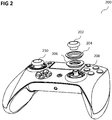
- FIG. 2 shows an illustration 200 of a game controller according to various embodiments.
- the game controller may include a left joystick 210 and a right joystick.
- the right joystick may include a removable thumb cap 202, a large ring 204 (which may be replaced by a small ring 206), and a counter piece 208 to secure the removable thumb cap 202.
- the thumb cap 202 may be so called because the thumb is the one controlling the movement of the joystick and the cap may be received by the controller end.
- the thumb cap 202 may be a plunger, i.e. the thumb cap 202 may have a protrusion under the cap that is inserted into the controller.
- the right joystick may have the removable thumb cap 202 to be able to put a swappable ring (for example the large ring 206 or the small ring 204) for different game sensitivity configuration.
- FIG. 3 shows a cross sectional view 300 of the game controller according to various embodiments.
- the removable thumb cap 202 may have an embedded ferromagnetic metal plate which may be attracted by a magnet 302 in the plunger of the joystick.
- the swappable rings (for example the large ring 204 and the small ring 206) may have embedded ferromagnetic metal inserts, which may be attracted by magnets 304 and 35 in the housing of the game controller.
- both the removable thumb cap 202 and the swappable rings may have ferromagnetic metal parts embedded on them which may be pulled by magnets 302, 304, 306 that keep them in place on the (game) controller.
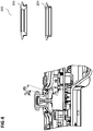
- FIG. 4 shows an illustration 400 of a range of motion of the thumb cap 202 (and thus the joystick) according to various embodiments.
- Each ring may offer (or provide or allow) a different angle (in other words: a different range of motion) that gives the different sensitivity outcome on game play.
- the small ring 206 may allow an angle ⁇ 1.
- the large ring 204 may provide an angle ⁇ 2.
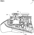
- FIG. 5 shows an illustration 500 of the large ring 204 according to various embodiments.
- An actuator 502 may be provided that activates a switch 504 to trigger a firmware change to recognize the shift in ring size.
- the large ring has no tab to push the switch 504 and may thus have a default firmware in use.
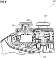
- FIG. 6 shows an illustration 600 of the small ring 206 according to various embodiments.
- the small ring 206 may have a tab 602 (in other words: a press tab feature) to push the switch 504 (via the actuator 502) thereby triggering a firmware change.
- the actuator 502 may maintain pressure on the switch 504 so that the firmware change is maintained.
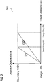
- FIG. 7 shows a chart 700 to explain how the ring size correlates the operation and sensitivity of the joystick according to various embodiments.
- the big ring may have a longer travel distance, it may be arbitrarily set as default for normal operation and may correspond to a default sensitivity value in the default firmware.
- the user may feel the short travel required to reach the boundary (the circumference of the joystick's physical operating circle) meanwhile the tab on the smaller ring may push the switch on the PCB (printed circuit) board through an actuator and the firmware may response by scaling the operating range (from center of the circle (origin) to the circumference of the circle (Boundary)) to the smaller ring, which may effectively increase the sensitivity value to a higher sensitivity value (of for example twice the sensitivity of the default value).
- the gradient of the graph of FIG. 7 equates to the Sensitivity of the joystick:
- the small ring has higher sensitivity than the large ring, and the speed of operation may be faster as it takes shorter distance and hence lesser time to reach the boundary from origin.
- FIG. 8 shows a diagram 800 illustrating that the speed of operation also increases with different rings according to various embodiments as it takes a short time to reach the boundary (circumference) from the center of the circle (origin) while the output value from 0% to 100% changes correspondingly at faster rate.
- the user may feel the short travel required to reach the boundary (the circumference of the Joystick's physical operating circle); meanwhile the tab on the smaller ring may push the switch on the PCB (printed circuit board) through an actuator and the firmware may response by scaling the operating range (from center of the circle (origin) to the circumference of the circle (boundary)) to the smaller ring, which effectively may increase the sensitivity value to a higher sensitivity value (for example twice the sensitivity of the default value).
- a variable sensitivity joystick may be provided.
- a controller variable joystick may be provided.
- a game controller variable sensitivity for thumbstick may be provided.
Landscapes
- Engineering & Computer Science (AREA)
- Multimedia (AREA)
- Human Computer Interaction (AREA)
- Physics & Mathematics (AREA)
- General Physics & Mathematics (AREA)
- Automation & Control Theory (AREA)
- Position Input By Displaying (AREA)
- Input From Keyboards Or The Like (AREA)
- Mechanical Control Devices (AREA)
- Switches With Compound Operations (AREA)
- User Interface Of Digital Computer (AREA)
Description
- Various embodiments generally relate to game controllers and methods for controlling a game controller.
- Game controllers are widely used in computer games.
US 5,963,196 A merely discloses that an inclinable range of a lever of an analog joystick may be restricted by a guide ring. As such, there may be a need for enhanced game controllers. - According to various embodiments, a game controller is provided. The game controller includes the features of claim 1.
- According to various embodiments, a method for controlling a game controller is provided. The method includes the features of claim 6.
- In the drawings, like reference characters generally refer to the same parts throughout the different views. The drawings are not necessarily to scale, emphasis instead generally being placed upon illustrating the principles of the invention. The dimensions of the various features or elements may be arbitrarily expanded or reduced for clarity. In the following description, various embodiments of the invention are described with reference to the following drawings, in which:
-
FIG. 1A shows a game controller according to various embodiments; -
FIG. 1B shows a flow diagram illustrating a method for controlling a game controller according to various embodiments; -
FIG. 2 shows an illustration of a game controller according to various embodiments; -
FIG. 3 shows a cross sectional view of the game controller according to various embodiments; -
FIG. 4 shows an illustration of a range of motion of the thumb cap according to various embodiments; -
FIG. 5 shows an illustration of the large ring according to various embodiments; -
FIG. 6 shows an illustration of the small ring according to various embodiments; -
FIG. 7 shows a chart to explain how the ring size correlates the operation and sensitivity of the joystick according to various embodiments; and -
FIG. 8 shows a diagram illustrating that the speed of operation also increases with different rings according to various embodiments. - The following detailed description refers to the accompanying drawings that show, by way of illustration, specific details and embodiments in which the invention may be practiced. These embodiments are described in sufficient detail to enable those skilled in the art to practice the invention. Other embodiments may be utilized and structural, and logical changes may be made without departing from the scope of the invention. The various embodiments are not necessarily mutually exclusive, as some embodiments can be combined with one or more other embodiments to form new embodiments.
- In this context, the game controller as described in this description may include a memory which is for example used in the processing carried out in the game controller. A memory used in the embodiments may be a volatile memory, for example a DRAM (Dynamic Random Access Memory) or a non-volatile memory, for example a PROM (Programmable Read Only Memory), an EPROM (Erasable PROM), EEPROM (Electrically Erasable PROM), or a flash memory, e.g., a floating gate memory, a charge trapping memory, an MRAM (Magnetoresistive Random Access Memory) or a PCRAM (Phase Change Random Access Memory).
- In an embodiment, a "circuit" may be understood as any kind of a logic implementing entity, which may be special purpose circuitry or a processor executing software stored in a memory, firmware, or any combination thereof. Thus, in an embodiment, a "circuit" may be a hard-wired logic circuit or a programmable logic circuit such as a programmable processor, e.g. a microprocessor (e.g. a Complex Instruction Set Computer (CISC) processor or a Reduced Instruction Set Computer (RISC) processor). A "circuit" may also be a processor executing software, e.g. any kind of computer program, e.g. a computer program using a virtual machine code such as e.g. Java. Any other kind of implementation of the respective functions which will be described in more detail below may also be understood as a "circuit" in accordance with an alternative embodiment.
- In the specification the term "comprising" shall be understood to have a broad meaning similar to the term "including" and will be understood to imply the inclusion of a stated integer or step or group of integers or steps but not the exclusion of any other integer or step or group of integers or steps. This definition also applies to variations on the term "comprising" such as "comprise" and "comprises".
- The reference to any prior art in this specification is not, and should not be taken as an acknowledgement or any form of suggestion that the referenced prior art forms part of the common general knowledge in Australia (or any other country).
- In order that the invention may be readily understood and put into practical effect, particular embodiments will now be described by way of examples and not limitations, and with reference to the figures.
- Various embodiments are provided for devices, and various embodiments are provided for methods. It will be understood that basic properties of the devices also hold for the methods and vice versa. Therefore, for sake of brevity, duplicate description of such properties may be omitted.
- It will be understood that any property described herein for a specific device may also hold for any device described herein. It will be understood that any property described herein for a specific method may also hold for any method described herein. Furthermore, it will be understood that for any device or method described herein, not necessarily all the components or steps described must be enclosed in the device or method, but only some (but not all) components or steps may be enclosed.
- The term "coupled" (or "connected") herein may be understood as electrically coupled or as mechanically coupled, for example attached or fixed, or just in contact without any fixation, and it will be understood that both direct coupling or indirect coupling (in other words: coupling without direct contact) may be provided.
- Game controllers are widely used in computer games.
- According to various embodiments, an enhanced game controller may be provided.
-
FIG. 1A shows agame controller 100 according to various embodiments. Thegame controller 100 may include a controller input 102 (for example a thumb controller; for example a joystick). Thegame controller 100 may further include a receivingportion 104 configured to alternatively receive a first ring or a second ring. The first ring may allow a first range of motion of thecontroller input 102. The second ring may allow a second range of motion of thecontroller input 102. Thegame controller 100 may further include amechanical switch 106 configured to receive mechanical input from at least one of the first ring or the second ring. Thecontroller input 102, thereceiving portion 104, and themechanical switch 106 may be coupled with each other, like indicated bylines 108, for example electrically coupled, for example using a line or a cable, and/ or mechanically coupled. - In other words, different ranges of motion of a joystick of a game controller may be provided depending on whether a first ring or a second ring is attached to the game controller.
- According to various embodiments, the at least one of the first ring or the second ring may include a tab configured to depress the
mechanical switch 106. - According to various embodiments, the at least one of the first ring or the second ring may include a tab configured to depress the
mechanical switch 106 via an actuator. - According to various embodiments, the first ring may include a tab configured to depress the
mechanical switch 106 via an actuator. - According to various embodiments, the second ring may be free from a tab configured to depress the
mechanical switch 106 via an actuator. - According to various embodiments, the
game controller 100 may be configured to transmit information indicating whether themechanical switch 106 is depressed to a computing device to which thegame controller 100 is connected. - According to various embodiments, the first ring may include a hole of a first diameter configured to surround the
controller input 102. - According to various embodiments, the second ring may include a hole of a second diameter configured to surround the
controller input 102. - According to various embodiments, the first diameter may be smaller than the second diameter.
- According to various embodiments, the first range of motion may be smaller than the second range of motion.
-
FIG. 1B shows a flow diagram 110 illustrating a method for controlling a game controller according to various embodiments. In 112, a controller input may be provided. In 114, a receiving portion may be provided to alternatively receive a first ring or a second ring, wherein the first ring allows a first range of motion of the controller input, and wherein the second ring allows a second range of motion of the controller input. In 116, mechanical input may be received from at least one of the first ring or the second ring. - According to various embodiments, the at least one of the first ring or the second ring may include a tab configured to depress the mechanical switch.
- According to various embodiments, the at least one of the first ring or the second ring may include a tab configured to depress the mechanical switch via an actuator.
- According to various embodiments, the first ring may include a tab configured to depress the mechanical switch via an actuator.
- According to various embodiments, the second ring may be free from a tab configured to depress the mechanical switch via an actuator.
- According to various embodiments, the method may further include transmitting information indicating whether the mechanical switch is depressed to a computing device to which the game controller is connected.
- According to various embodiments, the first ring may include a hole of a first diameter configured to surround the controller input.
- According to various embodiments, the second ring may include a hole of a second diameter configured to surround the controller input.
- According to various embodiments, the first diameter may be smaller than the second diameter.
- According to various embodiments, the first range of motion may be smaller than the second range of motion.
-
FIG. 2 shows anillustration 200 of a game controller according to various embodiments. The game controller may include aleft joystick 210 and a right joystick. The right joystick may include aremovable thumb cap 202, a large ring 204 (which may be replaced by a small ring 206), and acounter piece 208 to secure theremovable thumb cap 202. Thethumb cap 202 may be so called because the thumb is the one controlling the movement of the joystick and the cap may be received by the controller end. However, in an alternative embodiment, thethumb cap 202 may be a plunger, i.e. thethumb cap 202 may have a protrusion under the cap that is inserted into the controller. The right joystick may have theremovable thumb cap 202 to be able to put a swappable ring (for example thelarge ring 206 or the small ring 204) for different game sensitivity configuration. -
FIG. 3 shows a crosssectional view 300 of the game controller according to various embodiments. Theremovable thumb cap 202 may have an embedded ferromagnetic metal plate which may be attracted by amagnet 302 in the plunger of the joystick. The swappable rings (for example thelarge ring 204 and the small ring 206) may have embedded ferromagnetic metal inserts, which may be attracted bymagnets 304 and 35 in the housing of the game controller. - In other words, both the
removable thumb cap 202 and the swappable rings may have ferromagnetic metal parts embedded on them which may be pulled bymagnets -
FIG. 4 shows anillustration 400 of a range of motion of the thumb cap 202 (and thus the joystick) according to various embodiments. Each ring may offer (or provide or allow) a different angle (in other words: a different range of motion) that gives the different sensitivity outcome on game play. For example, thesmall ring 206 may allow an angle Ø1. For example, thelarge ring 204 may provide an angle Ø2. -
FIG. 5 shows anillustration 500 of thelarge ring 204 according to various embodiments. Anactuator 502 may be provided that activates aswitch 504 to trigger a firmware change to recognize the shift in ring size. The large ring has no tab to push theswitch 504 and may thus have a default firmware in use. -
FIG. 6 shows anillustration 600 of thesmall ring 206 according to various embodiments. Thesmall ring 206 may have a tab 602 (in other words: a press tab feature) to push the switch 504 (via the actuator 502) thereby triggering a firmware change. Theactuator 502 may maintain pressure on theswitch 504 so that the firmware change is maintained. -
FIG. 7 shows achart 700 to explain how the ring size correlates the operation and sensitivity of the joystick according to various embodiments. The big ring may have a longer travel distance, it may be arbitrarily set as default for normal operation and may correspond to a default sensitivity value in the default firmware. When the large ring is replaced with a smaller ring, the user may feel the short travel required to reach the boundary (the circumference of the joystick's physical operating circle) meanwhile the tab on the smaller ring may push the switch on the PCB (printed circuit) board through an actuator and the firmware may response by scaling the operating range (from center of the circle (origin) to the circumference of the circle (Boundary)) to the smaller ring, which may effectively increase the sensitivity value to a higher sensitivity value (of for example twice the sensitivity of the default value). The gradient of the graph ofFIG. 7 equates to the Sensitivity of the joystick: - Sensitivity = Gradient
- If Ø2 = 2 x Ø1
- Gradient G1 = 100/Ø1
- Gradient G2 = 100/Ø2 = 100/2S = 50/S
- Hence, G1 = 2 x G2.
- The small ring has higher sensitivity than the large ring, and the speed of operation may be faster as it takes shorter distance and hence lesser time to reach the boundary from origin.
-
FIG. 8 shows a diagram 800 illustrating that the speed of operation also increases with different rings according to various embodiments as it takes a short time to reach the boundary (circumference) from the center of the circle (origin) while the output value from 0% to 100% changes correspondingly at faster rate. - According to various embodiments, when the large ring is replaced with a smaller ring, the user may feel the short travel required to reach the boundary (the circumference of the Joystick's physical operating circle); meanwhile the tab on the smaller ring may push the switch on the PCB (printed circuit board) through an actuator and the firmware may response by scaling the operating range (from center of the circle (origin) to the circumference of the circle (boundary)) to the smaller ring, which effectively may increase the sensitivity value to a higher sensitivity value (for example twice the sensitivity of the default value).
- According to various embodiments, a variable sensitivity joystick may be provided. According to various embodiments, a controller variable joystick may be provided. According to various embodiments, a game controller variable sensitivity for thumbstick may be provided.
Claims (9)
- A game controller (100) comprising:a controller input (102); anda receiving portion (104) configured to alternatively receive a first ring or a second ring, wherein the first ring allows a first range of motion of the controller input (102), and wherein the second ring allows a second range of motion of the controller input (102);characterized in that the game controller (100) further comprises:a mechanical switch (106) configured to receive mechanical input from at least one of the first ring or the second ring;wherein the first ring comprises a tab (602) configured to depress the mechanical switch (106) via an actuator (502);wherein the second ring is free from a tab configured to depress the mechanical switch (106) via the actuator (502); andwherein the game controller (100) is configured to transmit information indicating whether the mechanical switch (106) is depressed to a computing device to which the game controller (100) is connected.
- The game controller (100) of claim 1,
wherein the first ring comprises a hole of a first diameter configured to surround the controller input (102). - The game controller (100) of claim 2,
wherein the second ring comprises a hole of a second diameter configured to surround the controller input (102). - The game controller (100) of claim 3,
wherein the first diameter is smaller than the second diameter. - The game controller (100) of any one of claims 1 to 4,
wherein the first range of motion is smaller than the second range of motion. - A method for controlling a game controller (100), the method comprising:providing a controller input (102); andproviding a receiving portion (104) to alternatively receive a first ring or a second ring, wherein the first ring allows a first range of motion of the controller input (102), and wherein the second ring allows a second range of motion of the controller input (102);characterized in that the method further comprises:receiving mechanical input from at least one of the first ring or the second ring;wherein the first ring comprises a tab (602) configured to depress the mechanical switch (106) via an actuator (502);wherein the second ring is free from a tab configured to depress the mechanical switch (106) via the actuator (502); andtransmitting information indicating whether the mechanical switch (106) is depressed to a computing device to which the game controller (100) is connected.
- The method of claim 6,
wherein the first ring comprises a hole of a first diameter configured to surround the controller input (102); and
wherein optionally the second ring comprises a hole of a second diameter configured to surround the controller input (102). - The method of claim 7,
wherein the first diameter is smaller than the second diameter. - The method of any one of claims 6 to 8,
wherein the first range of motion is smaller than the second range of motion.
Applications Claiming Priority (1)
| Application Number | Priority Date | Filing Date | Title |
|---|---|---|---|
| PCT/SG2016/050572 WO2018093328A1 (en) | 2016-11-21 | 2016-11-21 | Game controllers and methods for controlling a game controller |
Publications (3)
| Publication Number | Publication Date |
|---|---|
| EP3541487A1 EP3541487A1 (en) | 2019-09-25 |
| EP3541487A4 EP3541487A4 (en) | 2019-12-04 |
| EP3541487B1 true EP3541487B1 (en) | 2021-04-14 |
Family
ID=62146735
Family Applications (1)
| Application Number | Title | Priority Date | Filing Date |
|---|---|---|---|
| EP16921463.2A Active EP3541487B1 (en) | 2016-11-21 | 2016-11-21 | Game controllers and methods for controlling a game controller |
Country Status (6)
| Country | Link |
|---|---|
| US (1) | US10912993B2 (en) |
| EP (1) | EP3541487B1 (en) |
| CN (1) | CN110087744B (en) |
| AU (1) | AU2016429678B2 (en) |
| TW (1) | TWI739954B (en) |
| WO (1) | WO2018093328A1 (en) |
Families Citing this family (11)
| Publication number | Priority date | Publication date | Assignee | Title |
|---|---|---|---|---|
| WO2018078414A1 (en) * | 2016-10-24 | 2018-05-03 | Staragilis Limited | All in one mobile game controller |
| CN109426298B (en) * | 2017-09-01 | 2024-04-12 | 深圳市道通智能航空技术股份有限公司 | Control rod assembly and remote controller |
| TWM569644U (en) * | 2018-07-30 | 2018-11-11 | 正崴精密工業股份有限公司 | Game controller |
| FR3087665B1 (en) * | 2018-10-25 | 2022-03-18 | Bigben Interactive | JOYSTICK COMPRISING AT LEAST ONE PIVOTING CONTROL MEMB WHOSE STOP ANGLE IS MODIFIABLE |
| FR3087664B1 (en) * | 2018-10-25 | 2021-09-10 | Bigben Interactive | GAME CONTROLLER INCLUDING AT LEAST ONE REMOVABLE ADJUSTING ELEMENT ALLOWING THE ADJUSTMENT OF THE STOP ANGLE OF A SWIVELING CONTROLLER OF THE CONTROLLER |
| CN211132974U (en) * | 2019-09-04 | 2020-07-31 | 富港电子(昆山)有限公司 | Game handle |
| TWI829016B (en) * | 2021-10-01 | 2024-01-11 | 群光電子股份有限公司 | Game control device |
| GB2620152A (en) * | 2022-06-29 | 2024-01-03 | Sony Interactive Entertainment Inc | Insert for a controller |
| USD1077919S1 (en) * | 2022-08-26 | 2025-06-03 | Razer (Asia-Pacific) Pte. Ltd. | Controller |
| USD1099213S1 (en) * | 2024-09-26 | 2025-10-21 | Jiarui Zhu | Accessory for game console controllers |
| EP4741986A1 (en) * | 2024-11-12 | 2026-05-13 | Nintendo Co., Ltd. | Direction input apparatus and stick device |
Family Cites Families (32)
| Publication number | Priority date | Publication date | Assignee | Title |
|---|---|---|---|---|
| US4945357A (en) | 1988-08-29 | 1990-07-31 | Rotal Industries & Trading Ltd. | Joystick assembly |
| CA2194782C (en) * | 1995-05-10 | 2004-07-20 | Satoshi Nishiumi | Image processing system using analog joystick |
| JP3427366B2 (en) | 1995-08-17 | 2003-07-14 | 株式会社ナリシゲ | Adjustment mechanism of fine movement rate in joystick for fine movement operation |
| US5923317A (en) * | 1997-06-17 | 1999-07-13 | Thrustmaster, Inc. | Two-handed controller for video games and simulations |
| US20010048425A1 (en) | 2000-04-28 | 2001-12-06 | Partridge Gary R. | Device or component for alphanumeric and direction input |
| US6536298B1 (en) | 2000-06-30 | 2003-03-25 | Caterpillar Inc | Modular joystick |
| US6743100B1 (en) * | 2001-10-03 | 2004-06-01 | Gabe Neiser | Game controller |
| US20060181517A1 (en) * | 2005-02-11 | 2006-08-17 | Apple Computer, Inc. | Display actuator |
| US20050215321A1 (en) | 2004-03-29 | 2005-09-29 | Saied Hussaini | Video game controller with integrated trackball control device |
| CN2843562Y (en) | 2004-11-12 | 2006-12-06 | 乐迪卡游戏机有限公司 | Adjustable controller of video-frequency game handle |
| CN2784051Y (en) | 2005-03-16 | 2006-05-31 | 财团法人自行车暨健康科技工业研究发展中心 | Rocker devices combined with user-operated parts of sports or game mechanisms |
| WO2007040499A1 (en) | 2005-09-23 | 2007-04-12 | Intec, Inc. | Ergonomically configurable video game controller |
| JP4921854B2 (en) * | 2006-05-30 | 2012-04-25 | 東洋電装株式会社 | Joystick type switch device |
| US8795078B1 (en) | 2006-07-14 | 2014-08-05 | Ailive Inc. | Method and system providing compatibility between two different controllers |
| US8059090B2 (en) | 2007-03-28 | 2011-11-15 | Sony Ericsson Mobile Communications Ab | Navigation device |
| US20100069154A1 (en) | 2008-09-15 | 2010-03-18 | Claussen Seth A | Retroactive Compatibility Interactive System and Method Thereof |
| US8241126B2 (en) | 2009-11-04 | 2012-08-14 | Valve Corporation | Video game controller having user swappable control components |
| US20110183759A1 (en) * | 2010-01-27 | 2011-07-28 | Chu-Keng Lin | Joystick Controller |
| JP2013078374A (en) * | 2011-09-30 | 2013-05-02 | Universal Entertainment Corp | Game terminal with turnable lever-type operator |
| US9710072B1 (en) * | 2012-04-09 | 2017-07-18 | Performance Designed Products Llc | Interchangeable input mechanisms for control devices |
| US20140018173A1 (en) * | 2012-07-10 | 2014-01-16 | Ouya, Inc. | Video game controller with integrated touchpad |
| JP2014061225A (en) | 2012-09-24 | 2014-04-10 | Hori Co Ltd | Controller for game machine |
| CN105188864B (en) * | 2012-09-26 | 2016-11-16 | 雷蛇(亚太)私人有限公司 | Game console |
| US20140323220A1 (en) * | 2013-04-25 | 2014-10-30 | Cheng Uei Precision Industry Co., Ltd. | Game controller |
| CN105765495B (en) | 2013-09-09 | 2019-08-27 | 罗伯特·博世有限公司 | Reduced deadband for single joystick actuated vehicle control |
| WO2015078990A1 (en) | 2013-11-29 | 2015-06-04 | Ironburg Inventions | Controller for a games console |
| US10029175B2 (en) | 2013-11-29 | 2018-07-24 | Ironburg Inventions Ltd. | Controller for a games console |
| CN104492080A (en) | 2014-11-17 | 2015-04-08 | 深圳雷柏科技股份有限公司 | Method for adjusting sensitivity of rocker of game controller and game controller |
| EP3473309A1 (en) | 2015-01-09 | 2019-04-24 | Ironburg Inventions | Controller for a games console |
| US9925457B2 (en) * | 2015-06-09 | 2018-03-27 | Microsoft Technology Licensing, Llc | User-replaceable thumbstick top for game controller |
| TWM529204U (en) * | 2016-04-18 | 2016-09-21 | Kita Sensor Tech Co Ltd | Pressure transducer and control system |
| TWM529160U (en) * | 2016-05-12 | 2016-09-21 | Solid Year Co Ltd | Pressure sensor and pressure sensing system and pressure sensing switch using the same |
-
2016
- 2016-11-21 AU AU2016429678A patent/AU2016429678B2/en active Active
- 2016-11-21 EP EP16921463.2A patent/EP3541487B1/en active Active
- 2016-11-21 CN CN201680091005.7A patent/CN110087744B/en active Active
- 2016-11-21 WO PCT/SG2016/050572 patent/WO2018093328A1/en not_active Ceased
- 2016-11-21 US US16/462,482 patent/US10912993B2/en active Active
-
2017
- 2017-11-20 TW TW106140120A patent/TWI739954B/en active
Non-Patent Citations (1)
| Title |
|---|
| None * |
Also Published As
| Publication number | Publication date |
|---|---|
| EP3541487A4 (en) | 2019-12-04 |
| EP3541487A1 (en) | 2019-09-25 |
| WO2018093328A1 (en) | 2018-05-24 |
| AU2016429678B2 (en) | 2020-06-18 |
| US20190270006A1 (en) | 2019-09-05 |
| AU2016429678A1 (en) | 2019-06-06 |
| TWI739954B (en) | 2021-09-21 |
| CN110087744B (en) | 2020-09-29 |
| TW201832812A (en) | 2018-09-16 |
| CN110087744A (en) | 2019-08-02 |
| US10912993B2 (en) | 2021-02-09 |
Similar Documents
| Publication | Publication Date | Title |
|---|---|---|
| US10912993B2 (en) | Game controllers and methods for controlling a game controller | |
| US10592009B2 (en) | Input devices, methods for controlling an input device, and computer readable media | |
| CN113318434B (en) | Game information processing method and device and storage medium | |
| KR101580210B1 (en) | Game method and system for providing smart control for touch type | |
| TWI676917B (en) | Input devices | |
| US20200012357A1 (en) | Computer mice, computer mouse arrangements and mouse pad arrangements | |
| KR20180004195A (en) | Information processing method, terminal, and computer storage medium | |
| KR20160001600A (en) | Terminal device | |
| CN111032169B (en) | Highly extended analog joystick | |
| CN108635850B (en) | Information processing method, device and storage medium | |
| CN112969987B (en) | Provides tactile feedback for rotational control dynamics | |
| US10974144B2 (en) | Methods for emulating a virtual controller device, emulators, and computer-readable media | |
| AU2017424920B2 (en) | Slide button actuators | |
| US12390726B2 (en) | System and method for generating a scaled control signal for a video game console using a video game controller, and a stop member to limit displacement of a control stick | |
| CN111617474B (en) | Information processing method and device | |
| JP2019141129A5 (en) | ||
| CN109643169B (en) | Apparatus, method of controlling apparatus, and computer-readable medium | |
| AU2015415727B2 (en) | Wearable devices, methods for controlling a wearable device, and computer-readable media | |
| KR102936492B1 (en) | Military equipment control device and method | |
| CN116966542A (en) | Information processing method and device in game and electronic equipment | |
| US9639110B1 (en) | Elastic force transducer | |
| JP2014161419A5 (en) | ||
| KR20180097910A (en) | Curved shooting method and apparatus in VR game | |
| JP2016135435A5 (en) |
Legal Events
| Date | Code | Title | Description |
|---|---|---|---|
| STAA | Information on the status of an ep patent application or granted ep patent |
Free format text: STATUS: THE INTERNATIONAL PUBLICATION HAS BEEN MADE |
|
| PUAI | Public reference made under article 153(3) epc to a published international application that has entered the european phase |
Free format text: ORIGINAL CODE: 0009012 |
|
| STAA | Information on the status of an ep patent application or granted ep patent |
Free format text: STATUS: REQUEST FOR EXAMINATION WAS MADE |
|
| 17P | Request for examination filed |
Effective date: 20190516 |
|
| AK | Designated contracting states |
Kind code of ref document: A1 Designated state(s): AL AT BE BG CH CY CZ DE DK EE ES FI FR GB GR HR HU IE IS IT LI LT LU LV MC MK MT NL NO PL PT RO RS SE SI SK SM TR |
|
| AX | Request for extension of the european patent |
Extension state: BA ME |
|
| A4 | Supplementary search report drawn up and despatched |
Effective date: 20191104 |
|
| RIC1 | Information provided on ipc code assigned before grant |
Ipc: A63F 13/24 20140101AFI20191028BHEP Ipc: G05G 3/00 20060101ALI20191028BHEP Ipc: G05G 1/02 20060101ALI20191028BHEP |
|
| DAV | Request for validation of the european patent (deleted) | ||
| DAX | Request for extension of the european patent (deleted) | ||
| GRAP | Despatch of communication of intention to grant a patent |
Free format text: ORIGINAL CODE: EPIDOSNIGR1 |
|
| STAA | Information on the status of an ep patent application or granted ep patent |
Free format text: STATUS: GRANT OF PATENT IS INTENDED |
|
| INTG | Intention to grant announced |
Effective date: 20201109 |
|
| GRAS | Grant fee paid |
Free format text: ORIGINAL CODE: EPIDOSNIGR3 |
|
| GRAA | (expected) grant |
Free format text: ORIGINAL CODE: 0009210 |
|
| STAA | Information on the status of an ep patent application or granted ep patent |
Free format text: STATUS: THE PATENT HAS BEEN GRANTED |
|
| AK | Designated contracting states |
Kind code of ref document: B1 Designated state(s): AL AT BE BG CH CY CZ DE DK EE ES FI FR GB GR HR HU IE IS IT LI LT LU LV MC MK MT NL NO PL PT RO RS SE SI SK SM TR |
|
| REG | Reference to a national code |
Ref country code: GB Ref legal event code: FG4D |
|
| REG | Reference to a national code |
Ref country code: CH Ref legal event code: EP |
|
| REG | Reference to a national code |
Ref country code: DE Ref legal event code: R096 Ref document number: 602016056320 Country of ref document: DE |
|
| REG | Reference to a national code |
Ref country code: IE Ref legal event code: FG4D |
|
| REG | Reference to a national code |
Ref country code: AT Ref legal event code: REF Ref document number: 1381780 Country of ref document: AT Kind code of ref document: T Effective date: 20210515 |
|
| REG | Reference to a national code |
Ref country code: LT Ref legal event code: MG9D |
|
| REG | Reference to a national code |
Ref country code: AT Ref legal event code: MK05 Ref document number: 1381780 Country of ref document: AT Kind code of ref document: T Effective date: 20210414 |
|
| RAP4 | Party data changed (patent owner data changed or rights of a patent transferred) |
Owner name: RAZER (ASIA-PACIFIC) PTE. LTD. |
|
| REG | Reference to a national code |
Ref country code: NL Ref legal event code: MP Effective date: 20210414 |
|
| PG25 | Lapsed in a contracting state [announced via postgrant information from national office to epo] |
Ref country code: NL Free format text: LAPSE BECAUSE OF FAILURE TO SUBMIT A TRANSLATION OF THE DESCRIPTION OR TO PAY THE FEE WITHIN THE PRESCRIBED TIME-LIMIT Effective date: 20210414 Ref country code: HR Free format text: LAPSE BECAUSE OF FAILURE TO SUBMIT A TRANSLATION OF THE DESCRIPTION OR TO PAY THE FEE WITHIN THE PRESCRIBED TIME-LIMIT Effective date: 20210414 Ref country code: AT Free format text: LAPSE BECAUSE OF FAILURE TO SUBMIT A TRANSLATION OF THE DESCRIPTION OR TO PAY THE FEE WITHIN THE PRESCRIBED TIME-LIMIT Effective date: 20210414 Ref country code: BG Free format text: LAPSE BECAUSE OF FAILURE TO SUBMIT A TRANSLATION OF THE DESCRIPTION OR TO PAY THE FEE WITHIN THE PRESCRIBED TIME-LIMIT Effective date: 20210714 Ref country code: FI Free format text: LAPSE BECAUSE OF FAILURE TO SUBMIT A TRANSLATION OF THE DESCRIPTION OR TO PAY THE FEE WITHIN THE PRESCRIBED TIME-LIMIT Effective date: 20210414 Ref country code: LT Free format text: LAPSE BECAUSE OF FAILURE TO SUBMIT A TRANSLATION OF THE DESCRIPTION OR TO PAY THE FEE WITHIN THE PRESCRIBED TIME-LIMIT Effective date: 20210414 |
|
| PG25 | Lapsed in a contracting state [announced via postgrant information from national office to epo] |
Ref country code: IS Free format text: LAPSE BECAUSE OF FAILURE TO SUBMIT A TRANSLATION OF THE DESCRIPTION OR TO PAY THE FEE WITHIN THE PRESCRIBED TIME-LIMIT Effective date: 20210814 Ref country code: LV Free format text: LAPSE BECAUSE OF FAILURE TO SUBMIT A TRANSLATION OF THE DESCRIPTION OR TO PAY THE FEE WITHIN THE PRESCRIBED TIME-LIMIT Effective date: 20210414 Ref country code: GR Free format text: LAPSE BECAUSE OF FAILURE TO SUBMIT A TRANSLATION OF THE DESCRIPTION OR TO PAY THE FEE WITHIN THE PRESCRIBED TIME-LIMIT Effective date: 20210715 Ref country code: PT Free format text: LAPSE BECAUSE OF FAILURE TO SUBMIT A TRANSLATION OF THE DESCRIPTION OR TO PAY THE FEE WITHIN THE PRESCRIBED TIME-LIMIT Effective date: 20210816 Ref country code: PL Free format text: LAPSE BECAUSE OF FAILURE TO SUBMIT A TRANSLATION OF THE DESCRIPTION OR TO PAY THE FEE WITHIN THE PRESCRIBED TIME-LIMIT Effective date: 20210414 Ref country code: NO Free format text: LAPSE BECAUSE OF FAILURE TO SUBMIT A TRANSLATION OF THE DESCRIPTION OR TO PAY THE FEE WITHIN THE PRESCRIBED TIME-LIMIT Effective date: 20210714 Ref country code: RS Free format text: LAPSE BECAUSE OF FAILURE TO SUBMIT A TRANSLATION OF THE DESCRIPTION OR TO PAY THE FEE WITHIN THE PRESCRIBED TIME-LIMIT Effective date: 20210414 Ref country code: SE Free format text: LAPSE BECAUSE OF FAILURE TO SUBMIT A TRANSLATION OF THE DESCRIPTION OR TO PAY THE FEE WITHIN THE PRESCRIBED TIME-LIMIT Effective date: 20210414 |
|
| REG | Reference to a national code |
Ref country code: DE Ref legal event code: R097 Ref document number: 602016056320 Country of ref document: DE |
|
| PG25 | Lapsed in a contracting state [announced via postgrant information from national office to epo] |
Ref country code: DK Free format text: LAPSE BECAUSE OF FAILURE TO SUBMIT A TRANSLATION OF THE DESCRIPTION OR TO PAY THE FEE WITHIN THE PRESCRIBED TIME-LIMIT Effective date: 20210414 Ref country code: CZ Free format text: LAPSE BECAUSE OF FAILURE TO SUBMIT A TRANSLATION OF THE DESCRIPTION OR TO PAY THE FEE WITHIN THE PRESCRIBED TIME-LIMIT Effective date: 20210414 Ref country code: EE Free format text: LAPSE BECAUSE OF FAILURE TO SUBMIT A TRANSLATION OF THE DESCRIPTION OR TO PAY THE FEE WITHIN THE PRESCRIBED TIME-LIMIT Effective date: 20210414 Ref country code: ES Free format text: LAPSE BECAUSE OF FAILURE TO SUBMIT A TRANSLATION OF THE DESCRIPTION OR TO PAY THE FEE WITHIN THE PRESCRIBED TIME-LIMIT Effective date: 20210414 Ref country code: RO Free format text: LAPSE BECAUSE OF FAILURE TO SUBMIT A TRANSLATION OF THE DESCRIPTION OR TO PAY THE FEE WITHIN THE PRESCRIBED TIME-LIMIT Effective date: 20210414 Ref country code: SK Free format text: LAPSE BECAUSE OF FAILURE TO SUBMIT A TRANSLATION OF THE DESCRIPTION OR TO PAY THE FEE WITHIN THE PRESCRIBED TIME-LIMIT Effective date: 20210414 Ref country code: SM Free format text: LAPSE BECAUSE OF FAILURE TO SUBMIT A TRANSLATION OF THE DESCRIPTION OR TO PAY THE FEE WITHIN THE PRESCRIBED TIME-LIMIT Effective date: 20210414 |
|
| PLBE | No opposition filed within time limit |
Free format text: ORIGINAL CODE: 0009261 |
|
| STAA | Information on the status of an ep patent application or granted ep patent |
Free format text: STATUS: NO OPPOSITION FILED WITHIN TIME LIMIT |
|
| 26N | No opposition filed |
Effective date: 20220117 |
|
| PG25 | Lapsed in a contracting state [announced via postgrant information from national office to epo] |
Ref country code: IS Free format text: LAPSE BECAUSE OF FAILURE TO SUBMIT A TRANSLATION OF THE DESCRIPTION OR TO PAY THE FEE WITHIN THE PRESCRIBED TIME-LIMIT Effective date: 20210814 Ref country code: AL Free format text: LAPSE BECAUSE OF FAILURE TO SUBMIT A TRANSLATION OF THE DESCRIPTION OR TO PAY THE FEE WITHIN THE PRESCRIBED TIME-LIMIT Effective date: 20210414 |
|
| PG25 | Lapsed in a contracting state [announced via postgrant information from national office to epo] |
Ref country code: MC Free format text: LAPSE BECAUSE OF FAILURE TO SUBMIT A TRANSLATION OF THE DESCRIPTION OR TO PAY THE FEE WITHIN THE PRESCRIBED TIME-LIMIT Effective date: 20210414 |
|
| REG | Reference to a national code |
Ref country code: CH Ref legal event code: PL |
|
| PG25 | Lapsed in a contracting state [announced via postgrant information from national office to epo] |
Ref country code: LU Free format text: LAPSE BECAUSE OF NON-PAYMENT OF DUE FEES Effective date: 20211121 Ref country code: IT Free format text: LAPSE BECAUSE OF FAILURE TO SUBMIT A TRANSLATION OF THE DESCRIPTION OR TO PAY THE FEE WITHIN THE PRESCRIBED TIME-LIMIT Effective date: 20210414 Ref country code: BE Free format text: LAPSE BECAUSE OF NON-PAYMENT OF DUE FEES Effective date: 20211130 |
|
| REG | Reference to a national code |
Ref country code: BE Ref legal event code: MM Effective date: 20211130 |
|
| PG25 | Lapsed in a contracting state [announced via postgrant information from national office to epo] |
Ref country code: LI Free format text: LAPSE BECAUSE OF NON-PAYMENT OF DUE FEES Effective date: 20211130 Ref country code: CH Free format text: LAPSE BECAUSE OF NON-PAYMENT OF DUE FEES Effective date: 20211130 |
|
| PG25 | Lapsed in a contracting state [announced via postgrant information from national office to epo] |
Ref country code: IE Free format text: LAPSE BECAUSE OF NON-PAYMENT OF DUE FEES Effective date: 20211121 |
|
| P01 | Opt-out of the competence of the unified patent court (upc) registered |
Effective date: 20230327 |
|
| PG25 | Lapsed in a contracting state [announced via postgrant information from national office to epo] |
Ref country code: CY Free format text: LAPSE BECAUSE OF FAILURE TO SUBMIT A TRANSLATION OF THE DESCRIPTION OR TO PAY THE FEE WITHIN THE PRESCRIBED TIME-LIMIT Effective date: 20210414 |
|
| PG25 | Lapsed in a contracting state [announced via postgrant information from national office to epo] |
Ref country code: HU Free format text: LAPSE BECAUSE OF FAILURE TO SUBMIT A TRANSLATION OF THE DESCRIPTION OR TO PAY THE FEE WITHIN THE PRESCRIBED TIME-LIMIT; INVALID AB INITIO Effective date: 20161121 |
|
| PG25 | Lapsed in a contracting state [announced via postgrant information from national office to epo] |
Ref country code: MK Free format text: LAPSE BECAUSE OF FAILURE TO SUBMIT A TRANSLATION OF THE DESCRIPTION OR TO PAY THE FEE WITHIN THE PRESCRIBED TIME-LIMIT Effective date: 20210414 |
|
| PG25 | Lapsed in a contracting state [announced via postgrant information from national office to epo] |
Ref country code: MT Free format text: LAPSE BECAUSE OF FAILURE TO SUBMIT A TRANSLATION OF THE DESCRIPTION OR TO PAY THE FEE WITHIN THE PRESCRIBED TIME-LIMIT Effective date: 20210414 |
|
| PG25 | Lapsed in a contracting state [announced via postgrant information from national office to epo] |
Ref country code: TR Free format text: LAPSE BECAUSE OF FAILURE TO SUBMIT A TRANSLATION OF THE DESCRIPTION OR TO PAY THE FEE WITHIN THE PRESCRIBED TIME-LIMIT Effective date: 20210414 |
|
| PGFP | Annual fee paid to national office [announced via postgrant information from national office to epo] |
Ref country code: DE Payment date: 20251007 Year of fee payment: 10 |
|
| PGFP | Annual fee paid to national office [announced via postgrant information from national office to epo] |
Ref country code: GB Payment date: 20251016 Year of fee payment: 10 |
|
| PGFP | Annual fee paid to national office [announced via postgrant information from national office to epo] |
Ref country code: FR Payment date: 20251008 Year of fee payment: 10 |