EP3541154A1 - Passenger protection control device - Google Patents
Passenger protection control device Download PDFInfo
- Publication number
- EP3541154A1 EP3541154A1 EP17870480.5A EP17870480A EP3541154A1 EP 3541154 A1 EP3541154 A1 EP 3541154A1 EP 17870480 A EP17870480 A EP 17870480A EP 3541154 A1 EP3541154 A1 EP 3541154A1
- Authority
- EP
- European Patent Office
- Prior art keywords
- connector
- standing wall
- control device
- protection control
- passenger protection
- Prior art date
- Legal status (The legal status is an assumption and is not a legal conclusion. Google has not performed a legal analysis and makes no representation as to the accuracy of the status listed.)
- Granted
Links
Images




Classifications
-
- H—ELECTRICITY
- H05—ELECTRIC TECHNIQUES NOT OTHERWISE PROVIDED FOR
- H05K—PRINTED CIRCUITS; CASINGS OR CONSTRUCTIONAL DETAILS OF ELECTRIC APPARATUS; MANUFACTURE OF ASSEMBLAGES OF ELECTRICAL COMPONENTS
- H05K5/00—Casings, cabinets or drawers for electric apparatus
- H05K5/0026—Casings, cabinets or drawers for electric apparatus provided with connectors and printed circuit boards [PCB], e.g. automotive electronic control units
- H05K5/0047—Casings, cabinets or drawers for electric apparatus provided with connectors and printed circuit boards [PCB], e.g. automotive electronic control units having a two-part housing enclosing a PCB
- H05K5/0056—Casings, cabinets or drawers for electric apparatus provided with connectors and printed circuit boards [PCB], e.g. automotive electronic control units having a two-part housing enclosing a PCB characterized by features for protecting electronic components against vibration and moisture, e.g. potting, holders for relatively large capacitors
-
- B—PERFORMING OPERATIONS; TRANSPORTING
- B60—VEHICLES IN GENERAL
- B60R—VEHICLES, VEHICLE FITTINGS, OR VEHICLE PARTS, NOT OTHERWISE PROVIDED FOR
- B60R16/00—Electric or fluid circuits specially adapted for vehicles and not otherwise provided for; Arrangement of elements of electric or fluid circuits specially adapted for vehicles and not otherwise provided for
- B60R16/02—Electric or fluid circuits specially adapted for vehicles and not otherwise provided for; Arrangement of elements of electric or fluid circuits specially adapted for vehicles and not otherwise provided for electric constitutive elements
-
- B—PERFORMING OPERATIONS; TRANSPORTING
- B60—VEHICLES IN GENERAL
- B60R—VEHICLES, VEHICLE FITTINGS, OR VEHICLE PARTS, NOT OTHERWISE PROVIDED FOR
- B60R16/00—Electric or fluid circuits specially adapted for vehicles and not otherwise provided for; Arrangement of elements of electric or fluid circuits specially adapted for vehicles and not otherwise provided for
- B60R16/02—Electric or fluid circuits specially adapted for vehicles and not otherwise provided for; Arrangement of elements of electric or fluid circuits specially adapted for vehicles and not otherwise provided for electric constitutive elements
- B60R16/023—Electric or fluid circuits specially adapted for vehicles and not otherwise provided for; Arrangement of elements of electric or fluid circuits specially adapted for vehicles and not otherwise provided for electric constitutive elements for transmission of signals between vehicle parts or subsystems
- B60R16/0239—Electronic boxes
-
- B—PERFORMING OPERATIONS; TRANSPORTING
- B60—VEHICLES IN GENERAL
- B60R—VEHICLES, VEHICLE FITTINGS, OR VEHICLE PARTS, NOT OTHERWISE PROVIDED FOR
- B60R21/00—Arrangements or fittings on vehicles for protecting or preventing injuries to occupants or pedestrians in case of accidents or other traffic risks
- B60R21/01—Electrical circuits for triggering passive safety arrangements, e.g. airbags, safety belt tighteners, in case of vehicle accidents or impending vehicle accidents
- B60R21/013—Electrical circuits for triggering passive safety arrangements, e.g. airbags, safety belt tighteners, in case of vehicle accidents or impending vehicle accidents including means for detecting collisions, impending collisions or roll-over
-
- H—ELECTRICITY
- H02—GENERATION; CONVERSION OR DISTRIBUTION OF ELECTRIC POWER
- H02G—INSTALLATION OF ELECTRIC CABLES OR LINES, OR OF COMBINED OPTICAL AND ELECTRIC CABLES OR LINES
- H02G3/00—Installations of electric cables or lines or protective tubing therefor in or on buildings, equivalent structures or vehicles
- H02G3/02—Details
- H02G3/08—Distribution boxes; Connection or junction boxes
- H02G3/16—Distribution boxes; Connection or junction boxes structurally associated with support for line-connecting terminals within the box
-
- H—ELECTRICITY
- H05—ELECTRIC TECHNIQUES NOT OTHERWISE PROVIDED FOR
- H05K—PRINTED CIRCUITS; CASINGS OR CONSTRUCTIONAL DETAILS OF ELECTRIC APPARATUS; MANUFACTURE OF ASSEMBLAGES OF ELECTRICAL COMPONENTS
- H05K5/00—Casings, cabinets or drawers for electric apparatus
- H05K5/0026—Casings, cabinets or drawers for electric apparatus provided with connectors and printed circuit boards [PCB], e.g. automotive electronic control units
- H05K5/0069—Casings, cabinets or drawers for electric apparatus provided with connectors and printed circuit boards [PCB], e.g. automotive electronic control units having connector relating features for connecting the connector pins with the PCB or for mounting the connector body with the housing
-
- H—ELECTRICITY
- H05—ELECTRIC TECHNIQUES NOT OTHERWISE PROVIDED FOR
- H05K—PRINTED CIRCUITS; CASINGS OR CONSTRUCTIONAL DETAILS OF ELECTRIC APPARATUS; MANUFACTURE OF ASSEMBLAGES OF ELECTRICAL COMPONENTS
- H05K5/00—Casings, cabinets or drawers for electric apparatus
- H05K5/0026—Casings, cabinets or drawers for electric apparatus provided with connectors and printed circuit boards [PCB], e.g. automotive electronic control units
- H05K5/0078—Casings, cabinets or drawers for electric apparatus provided with connectors and printed circuit boards [PCB], e.g. automotive electronic control units specially adapted for acceleration sensors, e.g. crash sensors, airbag sensors
-
- H—ELECTRICITY
- H05—ELECTRIC TECHNIQUES NOT OTHERWISE PROVIDED FOR
- H05K—PRINTED CIRCUITS; CASINGS OR CONSTRUCTIONAL DETAILS OF ELECTRIC APPARATUS; MANUFACTURE OF ASSEMBLAGES OF ELECTRICAL COMPONENTS
- H05K5/00—Casings, cabinets or drawers for electric apparatus
- H05K5/06—Hermetically-sealed casings
- H05K5/069—Other details of the casing, e.g. wall structure, passage for a connector, a cable, a shaft
-
- B—PERFORMING OPERATIONS; TRANSPORTING
- B60—VEHICLES IN GENERAL
- B60R—VEHICLES, VEHICLE FITTINGS, OR VEHICLE PARTS, NOT OTHERWISE PROVIDED FOR
- B60R21/00—Arrangements or fittings on vehicles for protecting or preventing injuries to occupants or pedestrians in case of accidents or other traffic risks
- B60R21/01—Electrical circuits for triggering passive safety arrangements, e.g. airbags, safety belt tighteners, in case of vehicle accidents or impending vehicle accidents
- B60R2021/01286—Electronic control units
Definitions
- the present invention relates to an electronic control unit (ECU) which electrically controls the activation of an air bag, seat belt, etc. installed in an automobile as a safety device in order to protect passengers.
- This electronic control unit is hereinafter referred to as a passenger protection control device.
- air bag devices eject gas from an inflator upon crashing so as to deploy an air bag and protect passengers from impact upon crashing.
- activation of the inflator is electrically controlled by a passenger protection control device.
- this passenger protection control device has: a case 1 configured of a cover 11 and a rear cover 12; a connector 2 connected to a wire harness; and a printed circuit board 3.
- the printed circuit board 3 is accommodated in the case 1 so as to be isolated from the outside. In this state, as illustrated in FIG. 8 , a connection end surface 2a with a wire harness of the connector 2 attached to the printed circuit board 3 is exposed from the cover 11.
- the passenger protection control device is attached to a vehicle body by screwing each bolt inserted into the hole 12aa into a screw hole provided in the vehicle body.
- a control circuit for outputting a control signal for deploying the air bag is printed on the printed circuit board 3.
- Patent Documents 1 and 2 disclose a passenger protection control device, wherein protrusions and recessed parts are formed on the abutting surface between a connector and a cover, the abutting surface between the connector and a rear cover, and the abutting surface between the cover and the rear cover, these protrusions and recessed parts are fitted to each other, and a sealant is filled into each fitting part so as to be sealed. This configuration prevents water from infiltrating the interior of a case, preventing further damage to the printed circuit board.
- the sealant is disadvantageously cracked due to temperature changes, vibrations, secular changes, etc.
- the sealability of the cracked sealant may deteriorate, allowing water to infiltrate the interior of the case.
- a fitting part may not be able to be formed on the abutting surface between the connector and the rear cover.
- the abutting surface may not be able to be formed as a sealing surface or the sealant may not be able to be used due to a request by a customer. In such a case, water may infiltrate the interior of the case.
- An object of the passenger protection control device is to prevent the infiltration of water into the interior of a case without the use of a sealant.
- the passenger protection control device includes:
- the side wall regions for installing the connector remove a side wall from below the floor surface side. Consequently, because a space is present below the connector in the installation state, a liquid, for example, water tends to infiltrate the interior of a case. In the event of the infiltration of water, this water contacts the printed circuit board. Then, in the present invention, for example, in order to prevent the infiltration of water into the interior of the case, the first standing wall projecting so as to face the connector is provided on the rear cover.
- the planar region is formed in the head top part of the first standing wall of the rear cover configuring the case.
- this planar region has an inclined surface having a falling gradient facing outwardly from the cover configuring the case. Consequently, for example, even if water gets over the first standing wall to infiltrate the interior of the case, it stops at the planar region in the head top part, temporarily accumulates, and then flows down outwardly from the cover.
- an interval is desirably provided between the first standing wall of the rear cover and the connector in order to prevent the first standing wall of the rear cover from being pressed against and compressing the connector.
- the side wall parts are desirably of a length reaching an erecting part on the outer peripheral side of the first standing wall of the rear cover.
- a second standing wall projecting in the direction of a ceiling wall of the cover is desirably further provided on the inner peripheral side of the side wall portions other than the installation region of the rear cover.
- this second standing wall also desirably forms the planar region in the head top part, such that this planar region has an inclined surface having a falling gradient facing outwardly from the cover configuring the case.
- side wall portions other than the installation region of the connector are also desirably of a length reaching the erecting part on the outer peripheral side of the second standing wall, when the rear cover is attached to the cover.
- the second standing wall has the side walls of the cover on the outer peripheral side, there is no problem even if disposed below the printed circuit board.
- an interval is desirably provided between the second standing wall and the printed circuit board.
- the connector is attached so as to be placed on the printed circuit board, if the first standing wall is of the same height as the second standing wall, the interval between the connector and the first standing wall is larger than the interval between the printed circuit board and the second standing wall. Consequently, the height of the first standing wall is desirably formed so as to be higher than the height of the second standing wall.
- the interval between the connector and the first standing wall is desirably an interval in which, for example, water accumulated at the planar region in the head top part of the first standing wall does not contact the connector.
- the reason for this is that, if water accumulated at the planar region in the head top part of the first standing wall contacts the connector, the accumulated water tends not to flow down along the gradient of the planar region so as to face outwardly from the cover.
- the present invention has an inclined surface having a falling gradient facing outwardly from the cover at the planar region in the head top part of the first standing wall of the rear cover, even if water infiltrates the case, this water stops at the planar region in the head top part of the first standing wall, temporarily accumulates, and then flows down outwardly from the cover. Consequently, the present invention can effectively prevent the infiltration of water into the interior of a case without the use of a sealant.
- An object of the present invention is to prevent the infiltration of a liquid, for example, water to the interior of a case without the use of a sealant.
- the object is achieved by having an inclined surface with a falling gradient facing outwardly from the cover at the planar region in the head top part of the first standing wall formed in the portion of the rear cover in which at least the connector is installed.
- FIGS. 1 to 7 One example for carrying out the present invention will hereinafter be described with reference to FIGS. 1 to 7 .
- the passenger protection control device is configured to have a connector 2, a printed circuit board 3, and a case 1 which accommodates the connector 2 and the printed circuit board 3.
- the case 1 for example, is configured such that a resin cover 11 and a metal rear cover 12 are fastened using screw shafts 4 so as to be integrated.
- a control circuit for outputting a control signal to deploy an air bag is printed on the printed circuit board 3.
- a positioning pin 2b for insertion into the positioning hole 3a of the printed circuit board 3 is provided on the lower surface of the connector 2.
- the connector 2 is attached to one end of the printed circuit board 3.
- a connection end surface 2a with a wire harness of the connector 2 faces outward.
- a circular peripheral wall 2c is provided on the outer peripheral surface of the connector 2.
- the cover 11 has a box shape in which the periphery of this ceiling wall 11c is enclosed by the side walls and in which a floor surface is opened.
- the installation region thereof is removed from below the floor surface side to provide an opening 11b.
- a groove 11d fitted to the circular peripheral wall 2c of the connector 2 is formed in the opening 11b part of the side wall 11a 1 .
- a screw hole 11e of the screw shaft 4 for insertion into the insertion hole 3b of the printed circuit board 3 is provided at the attachment position of the printed circuit board 3 in the interior of the cover 11.
- the rear cover 12 plugs the floor surface of the cover 11, with an insertion hole 12c of the screw shaft 4 provided in a position coinciding with the screw hole 11e of the cover 11.
- the flange 12a which is projected outward so as to be exposed from the cover 11, is provided at three locations among four corners of the rear cover 12, with these flange 12a parts attached to a vehicle body.
- a second standing wall 12d of a rear plate 12 is formed so as to protrude on the inner peripheral side of the side walls 11 a 2 to 11 a 4 of the cover 11 below the printed circuit board 3.
- a first standing wall 12b of the rear plate 12 is formed so as to protrude in a portion disposed below the connector 2.
- the inner peripheral part of the printed circuit board 3 is enclosed by the first standing wall 12b and the second standing wall 12d.
- the positioning pin 2b of the connector 2 is inserted into a positioning hole 3a of the printed circuit board 3, while a contact terminal 2d of the connector 2 is connected to the control circuit printed on the printed circuit board 3 so as to attach the connector 2 to the printed circuit board 3.
- the circular peripheral wall 2c of the connector 2 is fitted to the groove 11d of the side wall 11a 1 so as to position the connector 2 and the printed circuit board 3 with the cover 11.
- connection end surface 2a with a wire harness of the connector 2 is exposed from the case 1, the printed circuit board 3 is enclosed by the cover 11 and the rear cover 12 so as to be isolated from the outside.
- the thus assembled passenger protection control device is attached to the vehicle body by inserting each bolt into a hole 12aa provided in the flange 12a of the rear cover 12.
- the thus assembled passenger protection control device has an interval between the first standing wall 12b of the rear cover 12 and the connector 2 as well as between the second standing wall 12d and the printed circuit board 3. In this manner, the first standing wall 12b and the second standing wall 12d are prevented from being pressed against and compressing the connector 2 and the printed circuit board 3.
- the passenger protection control device is attached with the connector 2 placed on the printed circuit board 3. Consequently, if the first standing wall 12b is of the same height as the second standing wall 12d, the interval d2 between the connector 2 and the first standing wall 12b is larger than the interval d1 between the printed circuit board 3 and the second standing wall 12d, causing water to have a tendency to infiltrate. Then, in the present example, the height h1 of the first standing wall 12b disposed below the connector 2 is formed so as to be higher than the height h2 of the second standing wall 12d disposed below the printed circuit board 3.
- a metal plate forming the rear cover 12 is folded in a projection shape to form the first and second standing walls 12b, 12d, such that planar regions 12bb, 12db are formed in head top parts 12ba, 12da.
- the interval d2 between the connector 2 and the planar region 12bb of the first standing wall 12b disposed below the connector 2 refers to an interval in which water 5 accumulated at the planar region 12bb in a head top part 12ba of the first standing wall 12b does not contact the connector 2.
- the planar region 12bb in the head top part 12ba of the first standing wall 12b is formed so as to serve as an inclined surface having a falling gradient facing outwardly from the cover 11.
- the interval d2 refers to the interval of the narrowest portion among the intervals between the connector 2 and the planar region 12bb.
- water which is attempting to infiltrate the interior of the case 1, stops at the planar region 12bb in the head top part 12ba of the first standing wall 12b, temporarily accumulates, and then flows down outwardly from the cover 11 so as to be discharged outside the device.
- the cover 11 excluding the region for installing the connector 2 has the side walls 11a 1 to 11a 4 . Consequently, in the present example, the side walls 11a 1 to 11a 4 are of a length reaching the vicinity of erecting parts 12bc, 12dc on the outer peripheral side of the first and second standing walls 12b, 12d of the rear cover 12, preventing the infiltration of water into the interior of the case 1 from these portions.
- only the first standing wall 12b disposed below the connector 2 forms the planar region 12bb in the head top part 12ba on an inclined surface having a falling gradient facing outwardly from the cover.
- the passenger protection control device described above is a preferred embodiment of the present invention, with other embodiments also capable of being executed or implemented by various methods.
- the present invention is not limited to the detailed components, sizes, configuration arrangements, etc. illustrated in the appended drawings.
- the expressions and terms used in the specification of the present application are for the purpose of description and are not limited thereto unless otherwise limited thereto.
- the front, rear, left, and right side walls 11a 1 to 11a may be separately configured, or may be integrally configured.
- the housing 1 may be made of metal, in addition to resin.
- the first standing wall 12b disposed below the connector 2, as well as the planar region 12db in the head top part 12da of the second standing wall 12d disposed below the printed circuit board 3, may be formed on an inclined surface having a falling gradient facing outwardly from the cover 11.
- the passenger protection control device is not limited to that which controls the activation to deploy an air bag, it is effective in controlling any device such as engine control and power steering control.
Landscapes
- Engineering & Computer Science (AREA)
- Microelectronics & Electronic Packaging (AREA)
- Mechanical Engineering (AREA)
- Architecture (AREA)
- Civil Engineering (AREA)
- Structural Engineering (AREA)
- Casings For Electric Apparatus (AREA)
- Connector Housings Or Holding Contact Members (AREA)
- Connection Or Junction Boxes (AREA)
Abstract
Description
- The present invention relates to an electronic control unit (ECU) which electrically controls the activation of an air bag, seat belt, etc. installed in an automobile as a safety device in order to protect passengers. This electronic control unit is hereinafter referred to as a passenger protection control device.
- For example, air bag devices eject gas from an inflator upon crashing so as to deploy an air bag and protect passengers from impact upon crashing. In these air bag devices, activation of the inflator is electrically controlled by a passenger protection control device.
- As illustrated in
FIGS. 5 and6 , this passenger protection control device has: acase 1 configured of acover 11 and arear cover 12; aconnector 2 connected to a wire harness; and a printedcircuit board 3. - In addition, by attaching the printed
circuit board 3 to thecover 11 together with therear cover 12 usingscrew shafts 4, the printedcircuit board 3 is accommodated in thecase 1 so as to be isolated from the outside. In this state, as illustrated inFIG. 8 , aconnection end surface 2a with a wire harness of theconnector 2 attached to the printedcircuit board 3 is exposed from thecover 11. - For example, three locations among four corners of the
rear cover 12 are projected outward so as to be exposed from thecover 11, with each hole 12aa provided in this projectedflange 12a. In addition, the passenger protection control device is attached to a vehicle body by screwing each bolt inserted into the hole 12aa into a screw hole provided in the vehicle body. - Moreover, upon determining that an automobile has crashed based on the acceleration or deceleration detected by a sensor, a control circuit for outputting a control signal for deploying the air bag is printed on the printed
circuit board 3. -
Patent Documents - Unfortunately, the sealant is disadvantageously cracked due to temperature changes, vibrations, secular changes, etc. The sealability of the cracked sealant may deteriorate, allowing water to infiltrate the interior of the case.
- Moreover, due to the limited product shape, for example, a fitting part may not be able to be formed on the abutting surface between the connector and the rear cover. Further, the abutting surface may not be able to be formed as a sealing surface or the sealant may not be able to be used due to a request by a customer. In such a case, water may infiltrate the interior of the case.
-
- Patent Document 1:
JP 2015-138923 A - Patent Document 2:
JP 2015-191995 A - Problems to be solved by the present invention are as follows:
- a) if a sealant is filled into a fitting part so as to be sealed but cracks, the sealability may deteriorate and allow water to infiltrate the interior of the case; and
- b) due to the limited product shape, if a fitting part cannot be formed, a sealing surface may not be able to be formed or the sealant may not be able to be used, causing water to potentially infiltrate the interior of the case.
- An object of the passenger protection control device according to the present invention is to prevent the infiltration of water into the interior of a case without the use of a sealant.
- That is, the passenger protection control device according to the present invention includes:
- a printed circuit board with a control circuit for outputting a control signal printed thereon;
- a connector attached to this printed circuit board; and
- a case that accommodates such that, while a connection end surface with a wire harness of the connector is exposed, the printed circuit board is isolated from the outside.
- In addition, most primarily characteristically, the case includes:
- a box shaped cover in which the periphery of a ceiling wall is enclosed by side walls and a floor surface is opened, with the connector installed in an opening provided on the side walls; and
- a rear cover that plugs the floor surface of the cover and has a first standing wall projecting so as to face the connector in the portion of the cover in which the connector is installed,
- wherein the first standing wall of the rear cover has a planar region in a head top part, while the planar region has an inclined surface having a falling gradient facing outwardly from the cover.
- The side wall regions for installing the connector remove a side wall from below the floor surface side. Consequently, because a space is present below the connector in the installation state, a liquid, for example, water tends to infiltrate the interior of a case. In the event of the infiltration of water, this water contacts the printed circuit board. Then, in the present invention, for example, in order to prevent the infiltration of water into the interior of the case, the first standing wall projecting so as to face the connector is provided on the rear cover.
- Moreover, in the present invention, the planar region is formed in the head top part of the first standing wall of the rear cover configuring the case. In addition, this planar region has an inclined surface having a falling gradient facing outwardly from the cover configuring the case. Consequently, for example, even if water gets over the first standing wall to infiltrate the interior of the case, it stops at the planar region in the head top part, temporarily accumulates, and then flows down outwardly from the cover.
- In the present invention, when the rear cover is attached to the cover, an interval is desirably provided between the first standing wall of the rear cover and the connector in order to prevent the first standing wall of the rear cover from being pressed against and compressing the connector.
- Moreover, in the present invention, in order to prevent the infiltration of water into the interior of the case from side wall parts of the cover disposed on both sides of the connector, for example, when the rear cover is attached to the cover, the side wall parts are desirably of a length reaching an erecting part on the outer peripheral side of the first standing wall of the rear cover.
- Moreover, in the present invention, for example, in order to prevent the infiltration of water from side wall portions other than the installation region of the connector, a second standing wall projecting in the direction of a ceiling wall of the cover is desirably further provided on the inner peripheral side of the side wall portions other than the installation region of the rear cover.
- In addition to the first standing wall, this second standing wall also desirably forms the planar region in the head top part, such that this planar region has an inclined surface having a falling gradient facing outwardly from the cover configuring the case.
- Moreover, in addition to the side wall parts of the cover disposed on both sides of the connector, side wall portions other than the installation region of the connector are also desirably of a length reaching the erecting part on the outer peripheral side of the second standing wall, when the rear cover is attached to the cover.
- Because the second standing wall has the side walls of the cover on the outer peripheral side, there is no problem even if disposed below the printed circuit board. As this time, in order to prevent the second standing wall from being pressed against the printed circuit board and compressing the printed circuit board, an interval is desirably provided between the second standing wall and the printed circuit board.
- Moreover, in the present invention, because the connector is attached so as to be placed on the printed circuit board, if the first standing wall is of the same height as the second standing wall, the interval between the connector and the first standing wall is larger than the interval between the printed circuit board and the second standing wall. Consequently, the height of the first standing wall is desirably formed so as to be higher than the height of the second standing wall.
- In this case, the interval between the connector and the first standing wall is desirably an interval in which, for example, water accumulated at the planar region in the head top part of the first standing wall does not contact the connector. The reason for this is that, if water accumulated at the planar region in the head top part of the first standing wall contacts the connector, the accumulated water tends not to flow down along the gradient of the planar region so as to face outwardly from the cover.
- Because the present invention has an inclined surface having a falling gradient facing outwardly from the cover at the planar region in the head top part of the first standing wall of the rear cover, even if water infiltrates the case, this water stops at the planar region in the head top part of the first standing wall, temporarily accumulates, and then flows down outwardly from the cover. Consequently, the present invention can effectively prevent the infiltration of water into the interior of a case without the use of a sealant.
-
-
FIG. 1 is a longitudinal cross-sectional perspective view when the passenger protection control device according to the present invention is seen from the rear cover side. -
FIG. 2 is a view seen from the direction of the cross section ofFIG. 1 . -
FIG. 3 is a perspective view when the rear cover configuring a case of the passenger protection control device according to the present invention is seen from the interior of the case. -
FIG. 4 is a side view of the rear cover configuring the case of the passenger protection control device according to the present invention. -
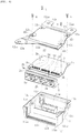
FIG. 5 is an exploded perspective view when the passenger protection control device according to the present invention is seen from the cover side. -
FIG. 6 is an exploded perspective view when the passenger protection control device according to the present invention is seen from the rear cover side. -
FIG. 7 is a view describing the effects of the configuration of the present invention, wherein (a) is a view employing the configuration of the present invention, while (b) is a view not employing the configuration of the present invention. -
FIG. 8 is a perspective view when the passenger protection control device is seen from the cover side. - An object of the present invention is to prevent the infiltration of a liquid, for example, water to the interior of a case without the use of a sealant.
- In addition, the object is achieved by having an inclined surface with a falling gradient facing outwardly from the cover at the planar region in the head top part of the first standing wall formed in the portion of the rear cover in which at least the connector is installed.
- One example for carrying out the present invention will hereinafter be described with reference to
FIGS. 1 to 7 . - As described with reference to
FIGS. 5 and6 in the background art, the passenger protection control device is configured to have aconnector 2, a printedcircuit board 3, and acase 1 which accommodates theconnector 2 and the printedcircuit board 3. Among these, thecase 1, for example, is configured such that aresin cover 11 and a metalrear cover 12 are fastened usingscrew shafts 4 so as to be integrated. - For example, when a sensor, electronic element, etc. are mounted on the printed
circuit board 3, and an automobile crash is determined based on the acceleration or deceleration detected by the sensor, a control circuit for outputting a control signal to deploy an air bag, for example, is printed on the printedcircuit board 3. - A
positioning hole 3a of theconnector 2, for example, is provided at two locations on one end of this printedcircuit board 3. Moreover, on both sides (the other end of the printedcircuit board 3 and the central part closer to one end thereof), aninsertion hole 3b of thescrew shaft 4 for attaching therear cover 12 to thecover 11, for example, is provided at four locations. - In contrast, a
positioning pin 2b for insertion into thepositioning hole 3a of the printedcircuit board 3 is provided on the lower surface of theconnector 2. In addition, when thispositioning pin 2b is inserted into thepositioning hole 3a, theconnector 2 is attached to one end of the printedcircuit board 3. In this attached state, aconnection end surface 2a with a wire harness of theconnector 2 faces outward. Moreover, a circularperipheral wall 2c is provided on the outer peripheral surface of theconnector 2. - For example, with
side walls 11a1 to 11a4 provided such that they hang down from the front, rear, left, and right of aceiling wall 11c, thecover 11 has a box shape in which the periphery of thisceiling wall 11c is enclosed by the side walls and in which a floor surface is opened. In theside wall 11a1 for installing theconnector 2 among theside walls 11a1 to 11a4, the installation region thereof is removed from below the floor surface side to provide anopening 11b. In addition, agroove 11d fitted to the circularperipheral wall 2c of theconnector 2 is formed in theopening 11b part of theside wall 11a1. Moreover, a screw hole 11e of thescrew shaft 4 for insertion into theinsertion hole 3b of the printedcircuit board 3 is provided at the attachment position of the printedcircuit board 3 in the interior of thecover 11. - In contrast, the
rear cover 12 plugs the floor surface of thecover 11, with aninsertion hole 12c of thescrew shaft 4 provided in a position coinciding with the screw hole 11e of thecover 11. Moreover, theflange 12a, which is projected outward so as to be exposed from thecover 11, is provided at three locations among four corners of therear cover 12, with theseflange 12a parts attached to a vehicle body. Moreover, asecond standing wall 12d of arear plate 12 is formed so as to protrude on the inner peripheral side of theside walls 11 a2 to 11 a4 of thecover 11 below the printedcircuit board 3. In contrast, afirst standing wall 12b of therear plate 12 is formed so as to protrude in a portion disposed below theconnector 2. In addition, the inner peripheral part of the printedcircuit board 3 is enclosed by thefirst standing wall 12b and thesecond standing wall 12d. - In the abovementioned passenger protection control device, the
positioning pin 2b of theconnector 2 is inserted into apositioning hole 3a of the printedcircuit board 3, while acontact terminal 2d of theconnector 2 is connected to the control circuit printed on the printedcircuit board 3 so as to attach theconnector 2 to the printedcircuit board 3. In this state, the circularperipheral wall 2c of theconnector 2 is fitted to thegroove 11d of theside wall 11a1 so as to position theconnector 2 and the printedcircuit board 3 with thecover 11. - In this state, because the screw holes 11e of the
cover 11 coincide with theinsertion holes 3b of the printedcircuit board 3, the insertion holes 12c are made to coincide with the screw holes 11e and theinsertion holes 3b so as to fasten and integraterear cover 12 to thecover 11 using thescrew shafts 4. - In this manner, while the
connection end surface 2a with a wire harness of theconnector 2 is exposed from thecase 1, the printedcircuit board 3 is enclosed by thecover 11 and therear cover 12 so as to be isolated from the outside. The thus assembled passenger protection control device is attached to the vehicle body by inserting each bolt into a hole 12aa provided in theflange 12a of therear cover 12. - As illustrated in
FIG. 2 , the thus assembled passenger protection control device has an interval between thefirst standing wall 12b of therear cover 12 and theconnector 2 as well as between thesecond standing wall 12d and the printedcircuit board 3. In this manner, thefirst standing wall 12b and thesecond standing wall 12d are prevented from being pressed against and compressing theconnector 2 and the printedcircuit board 3. - Moreover, the passenger protection control device is attached with the
connector 2 placed on the printedcircuit board 3. Consequently, if thefirst standing wall 12b is of the same height as thesecond standing wall 12d, the interval d2 between theconnector 2 and thefirst standing wall 12b is larger than the interval d1 between the printedcircuit board 3 and thesecond standing wall 12d, causing water to have a tendency to infiltrate. Then, in the present example, the height h1 of thefirst standing wall 12b disposed below theconnector 2 is formed so as to be higher than the height h2 of thesecond standing wall 12d disposed below the printedcircuit board 3. - In the present invention, as illustrated in
FIGS. 1 and2 , a metal plate forming therear cover 12, for example, is folded in a projection shape to form the first and second standingwalls - Moreover, in the present example, the interval d2 between the
connector 2 and the planar region 12bb of thefirst standing wall 12b disposed below theconnector 2 refers to an interval in whichwater 5 accumulated at the planar region 12bb in a head top part 12ba of thefirst standing wall 12b does not contact theconnector 2. - At this time, as illustrated in
FIG. 7(b) , if the planar region 12bb is horizontal,water 5, which is attempting to infiltrate the interior of thecase 1, may flow in thecase 1. Ifwater 5 flows in thecase 1, it will likely damage the printedcircuit board 3. - Then, in the present invention, for example, the planar region 12bb in the head top part 12ba of the
first standing wall 12b is formed so as to serve as an inclined surface having a falling gradient facing outwardly from thecover 11. In this case, the interval d2 refers to the interval of the narrowest portion among the intervals between theconnector 2 and the planar region 12bb. - With such a configuration, as illustrated in
FIG. 7(a) , water, which is attempting to infiltrate the interior of thecase 1, stops at the planar region 12bb in the head top part 12ba of thefirst standing wall 12b, temporarily accumulates, and then flows down outwardly from thecover 11 so as to be discharged outside the device. - Moreover, the
cover 11 excluding the region for installing theconnector 2 has theside walls 11a1 to 11a4. Consequently, in the present example, theside walls 11a1 to 11a4 are of a length reaching the vicinity of erecting parts 12bc, 12dc on the outer peripheral side of the first and second standingwalls rear cover 12, preventing the infiltration of water into the interior of thecase 1 from these portions. In the present example, only thefirst standing wall 12b disposed below theconnector 2 forms the planar region 12bb in the head top part 12ba on an inclined surface having a falling gradient facing outwardly from the cover. - The present invention is not limited to the abovementioned example, and embodiments may be appropriately changed as long as they are included in the category of technical ideas described in each claim.
- That is, the passenger protection control device described above is a preferred embodiment of the present invention, with other embodiments also capable of being executed or implemented by various methods. Unless otherwise described as limitations in the specification of the present application, the present invention is not limited to the detailed components, sizes, configuration arrangements, etc. illustrated in the appended drawings. Moreover, the expressions and terms used in the specification of the present application are for the purpose of description and are not limited thereto unless otherwise limited thereto.
- For example, as long as the entire periphery of the
cover 11 is enclosed by the side walls, for example, the front, rear, left, andright side walls 11a1 to 11a may be separately configured, or may be integrally configured. Moreover, thehousing 1 may be made of metal, in addition to resin. Moreover, thefirst standing wall 12b disposed below theconnector 2, as well as the planar region 12db in the head top part 12da of thesecond standing wall 12d disposed below the printedcircuit board 3, may be formed on an inclined surface having a falling gradient facing outwardly from thecover 11. - As described above, the passenger protection control device according to the present invention is not limited to that which controls the activation to deploy an air bag, it is effective in controlling any device such as engine control and power steering control.
-
- 1 Case
- 11 Cover
- 11a1 to 11a4 Side walls
- 11b Opening
- 11c Ceiling wall
- 12 Rear cover
- 12a Flange part
- 12b First standing wall
- 12ba Head top part
- 12bb Planar region
- 12bc Erecting part
- 12d Second standing wall
- 12da Head top part
- 12db Planar region
- 12dc Erecting part
- 2 Connector
- 2a Connection end surface
- 3 Printed circuit board
- h1 Height of the first standing wall
- h2 Height of the second standing wall
- d1 Interval between the printed circuit board and the second standing wall
- d2 Interval between the connector and the first standing wall
Claims (37)
- A passenger protection control device, comprising: a printed circuit board with a control circuit for outputting a control signal printed thereon;
a connector attached to this printed circuit board; and
a case that accommodates such that, while a connection end surface with a wire harness of the connector is exposed, the printed circuit board is isolated from the outside,
wherein the case comprises:a box shaped cover in which the periphery of a ceiling wall is enclosed by side walls and a floor surface is opened, with the connector installed in an opening provided on the side walls; anda rear cover that plugs the floor surface of the cover and has a first standing wall projecting so as to face the connector in the portion of the cover in which the connector is installed,wherein the first standing wall of the rear cover has a planar region in a head top part, while the planar region has an inclined surface having a falling gradient facing outwardly from the cover. - The passenger protection control device according to claim 1, wherein an interval is provided between the first standing wall of the rear cover and the connector.
- The passenger protection control device according to claim 1 or 2, wherein, when the rear cover is attached to the cover, side wall parts of the cover disposed on both sides of the connector are of a length reaching an erecting part on the outer peripheral side of the first standing wall of the rear cover.
- The passenger protection control device according to claim 1 or 2, wherein the rear cover further comprises a flange for attachment to a vehicle body projecting outwardly from the cover.
- The passenger protection control device according to claim 3, wherein the rear cover further comprises a flange for attachment to a vehicle body projecting outwardly from the cover.
- The passenger protection control device according to claim 1, 2, or 5, wherein the rear cover further comprises a second standing wall projecting in the direction of the ceiling wall of the cover, on the inner peripheral side of side wall portions other than the installation region of the connector.
- The passenger protection control device according to claim 3, wherein the rear cover further comprises a second standing wall projecting in the direction of the ceiling wall of the cover, on the inner peripheral side of side wall portions other than the installation region of the connector.
- The passenger protection control device according to claim 4, wherein the rear cover further comprises a second standing wall projecting in the direction of the ceiling wall of the cover, on the inner peripheral side of side wall portions other than the installation region of the connector.
- The passenger protection control device according to claim 6, wherein the second standing wall has a planar region in the head top part, while the planar region has an inclined surface having a falling gradient facing outwardly from the cover.
- The passenger protection control device according to claim 7 or 8, wherein the second standing wall has a planar region in the head top part, while the planar region has an inclined surface having a falling gradient facing outwardly from the cover.
- The passenger protection control device according to claim 6, wherein the second standing wall of the rear cover is disposed below the printed circuit board.
- The passenger protection control device according to any one of claims 7 to 9, wherein the second standing wall of the rear cover is disposed below the printed circuit board.
- The passenger protection control device according to claim 10, wherein the second standing wall of the rear cover is disposed below the printed circuit board.
- The passenger protection control device according to claim 6, wherein an interval is provided between the second standing wall of the rear cover and the printed circuit board.
- The passenger protection control device according to any one of claims 7 to 9, 11, and 13, wherein an interval is provided between the second standing wall of the rear cover and the printed circuit board.
- The passenger protection control device according to claim 10, wherein an interval is provided between the second standing wall of the rear cover and the printed circuit board.
- The passenger protection control device according to claim 12, wherein an interval is provided between the second standing wall of the rear cover and the printed circuit board.
- The passenger protection control device according to claim 6, wherein the height of the first standing wall disposed below the connector is formed so as to be higher than the height of the second standing wall.
- The passenger protection control device according to any one of claims 7 to 9, 11, 13, 14, 16, and 17, wherein the height of the first standing wall disposed below the connector is formed so as to be higher than the height of the second standing wall.
- The passenger protection control device according to claim 10, wherein the height of the first standing wall disposed below the connector is formed so as to be higher than the height of the second standing wall.
- The passenger protection control device according to claim 12, wherein the height of the first standing wall disposed below the connector is formed so as to be higher than the height of the second standing wall.
- The passenger protection control device according to claim 15, wherein the height of the first standing wall disposed below the connector is formed so as to be higher than the height of the second standing wall.
- The passenger protection control device according to claim 6, wherein, when the rear cover is attached to the cover, portions other than the installation region of the connector on the side walls are of a length reaching an erecting part on the outer peripheral side of the second standing wall of the rear cover.
- The passenger protection control device according to any one of claims 7 to 9, 11, 13, 14, 16 to 18, and 20 to 22, wherein, when the rear cover is attached to the cover, portions other than the installation region of the connector on the side walls are of a length reaching an erecting part on the outer peripheral side of the second standing wall of the rear cover.
- The passenger protection control device according to claim 10, wherein, when the rear cover is attached to the cover, portions other than the installation region of the connector on the side walls are of a length reaching an erecting part on the outer peripheral side of the second standing wall of the rear cover.
- The passenger protection control device according to claim 12, wherein, when the rear cover is attached to the cover, portions other than the installation region of the connector on the side walls are of a length reaching an erecting part on the outer peripheral side of the second standing wall of the rear cover.
- The passenger protection control device according to claim 15, wherein, when the rear cover is attached to the cover, portions other than the installation region of the connector on the side walls are of a length reaching an erecting part on the outer peripheral side of the second standing wall of the rear cover.
- The passenger protection control device according to claim 19, wherein, when the rear cover is attached to the cover, portions other than the installation region of the connector on the side walls are of a length reaching an erecting part on the outer peripheral side of the second standing wall of the rear cover.
- The passenger protection control device according to any one of claims 1, 2, 5, 7 to 9, 11, 13, 14, 16 to 18, 20 to 23, and 25 to 28, wherein the interval between the connector and the first standing wall disposed below the connector is an interval that stops infiltration into the case at the planar region formed in the head top part of the first standing wall so as to prevent an accumulated liquid from contacting the connector.
- The passenger protection control device according to claim 3, wherein the interval between the connector and the first standing wall disposed below the connector is an interval that stops infiltration into the case at the planar region formed in the head top part of the first standing wall so as to prevent an accumulated liquid from contacting the connector.
- The passenger protection control device according to claim 4, wherein the interval between the connector and the first standing wall disposed below the connector is an interval that stops infiltration into the case at the planar region formed in the head top part of the first standing wall so as to prevent an accumulated liquid from contacting the connector.
- The passenger protection control device according to claim 6, wherein the interval between the connector and the first standing wall disposed below the connector is an interval that stops infiltration into the case at the planar region formed in the head top part of the first standing wall so as to prevent an accumulated liquid from contacting the connector.
- The passenger protection control device according to claim 10, wherein the interval between the connector and the first standing wall disposed below the connector is an interval that stops infiltration into the case at the planar region formed in the head top part of the first standing wall so as to prevent an accumulated liquid from contacting the connector.
- The passenger protection control device according to claim 12, wherein the interval between the connector and the first standing wall disposed below the connector is an interval that stops infiltration into the case at the planar region formed in the head top part of the first standing wall so as to prevent an accumulated liquid from contacting the connector.
- The passenger protection control device according to claim 15, wherein the interval between the connector and the first standing wall disposed below the connector is an interval that stops infiltration into the case at the planar region formed in the head top part of the first standing wall so as to prevent an accumulated liquid from contacting the connector.
- The passenger protection control device according to claim 19, wherein the interval between the connector and the first standing wall disposed below the connector is an interval that stops infiltration into the case at the planar region formed in the head top part of the first standing wall so as to prevent an accumulated liquid from contacting the connector.
- The passenger protection control device according to claim 24, wherein the interval between the connector and the first standing wall disposed below the connector is an interval that stops infiltration into the case at the planar region formed in the head top part of the first standing wall so as to prevent an accumulated liquid from contacting the connector.
Applications Claiming Priority (2)
| Application Number | Priority Date | Filing Date | Title |
|---|---|---|---|
| JP2016220355 | 2016-11-11 | ||
| PCT/JP2017/036792 WO2018088095A1 (en) | 2016-11-11 | 2017-10-11 | Passenger protection control device |
Publications (3)
| Publication Number | Publication Date |
|---|---|
| EP3541154A1 true EP3541154A1 (en) | 2019-09-18 |
| EP3541154A4 EP3541154A4 (en) | 2020-06-17 |
| EP3541154B1 EP3541154B1 (en) | 2021-07-14 |
Family
ID=62109518
Family Applications (1)
| Application Number | Title | Priority Date | Filing Date |
|---|---|---|---|
| EP17870480.5A Active EP3541154B1 (en) | 2016-11-11 | 2017-10-11 | Passenger protection control device |
Country Status (5)
| Country | Link |
|---|---|
| US (1) | US11026340B2 (en) |
| EP (1) | EP3541154B1 (en) |
| JP (1) | JP6696000B2 (en) |
| CN (1) | CN109937616B (en) |
| WO (1) | WO2018088095A1 (en) |
Families Citing this family (6)
| Publication number | Priority date | Publication date | Assignee | Title |
|---|---|---|---|---|
| JP7351652B2 (en) * | 2019-06-26 | 2023-09-27 | 矢崎総業株式会社 | electronic unit |
| CN210959066U (en) * | 2019-09-19 | 2020-07-07 | 哈曼贝克自动系统股份有限公司 | Electronic device and waterproof structure for electronic device |
| JP7264002B2 (en) * | 2019-09-30 | 2023-04-25 | 住友電装株式会社 | electric junction box |
| JP7636384B2 (en) * | 2022-11-04 | 2025-02-26 | パナソニックオートモーティブシステムズ株式会社 | Electronics |
| US12389559B2 (en) * | 2022-11-21 | 2025-08-12 | Zf Friedrichshafen Ag | Housing assembly having breakaway leg members |
| US12446172B2 (en) * | 2022-11-21 | 2025-10-14 | Zf Friedrichshafen Ag | Housing assembly having breakaway leg members |
Family Cites Families (14)
| Publication number | Priority date | Publication date | Assignee | Title |
|---|---|---|---|---|
| EP1262853A1 (en) * | 2001-06-01 | 2002-12-04 | Nokia Corporation | Input device |
| JP4410242B2 (en) * | 2006-12-27 | 2010-02-03 | 三菱電機株式会社 | Electronic control device and manufacturing method thereof |
| JP2009056991A (en) * | 2007-09-03 | 2009-03-19 | Takata Corp | Seatbelt retractor and seatbelt device having the same |
| JP2009064916A (en) | 2007-09-05 | 2009-03-26 | Kokusan Denki Co Ltd | Electronic unit and manufacturing method thereof |
| JP2009131088A (en) * | 2007-11-26 | 2009-06-11 | Furukawa Electric Co Ltd:The | Electrical junction box |
| JP2011150895A (en) * | 2010-01-21 | 2011-08-04 | Toyota Motor Corp | Connector connection structure |
| JP5759914B2 (en) * | 2012-02-09 | 2015-08-05 | 日立オートモティブシステムズ株式会社 | Electronic control unit |
| JP5930287B2 (en) * | 2012-02-27 | 2016-06-08 | 株式会社オートネットワーク技術研究所 | Electrical junction box |
| JP5590065B2 (en) * | 2012-04-06 | 2014-09-17 | 株式会社デンソー | Electronic control unit for vehicle |
| JP6023524B2 (en) | 2012-09-14 | 2016-11-09 | 日立オートモティブシステムズ株式会社 | Electronic control unit |
| JP5610040B2 (en) * | 2013-06-14 | 2014-10-22 | 株式会社デンソー | Waterproof housing and waterproof device |
| JP5746386B1 (en) | 2014-01-24 | 2015-07-08 | 三菱電機株式会社 | Waterproof control unit and method of assembling the same |
| JP5745127B1 (en) | 2014-03-28 | 2015-07-08 | 三菱電機株式会社 | Waterproof control unit |
| JP5901725B1 (en) * | 2014-10-17 | 2016-04-13 | 三菱電機株式会社 | Waterproof control unit and its assembly method |
-
2017
- 2017-10-11 US US16/348,885 patent/US11026340B2/en active Active
- 2017-10-11 JP JP2018550078A patent/JP6696000B2/en active Active
- 2017-10-11 CN CN201780069899.4A patent/CN109937616B/en active Active
- 2017-10-11 WO PCT/JP2017/036792 patent/WO2018088095A1/en not_active Ceased
- 2017-10-11 EP EP17870480.5A patent/EP3541154B1/en active Active
Also Published As
| Publication number | Publication date |
|---|---|
| EP3541154B1 (en) | 2021-07-14 |
| WO2018088095A1 (en) | 2018-05-17 |
| CN109937616B (en) | 2021-07-27 |
| EP3541154A4 (en) | 2020-06-17 |
| US20190281718A1 (en) | 2019-09-12 |
| CN109937616A (en) | 2019-06-25 |
| US11026340B2 (en) | 2021-06-01 |
| JPWO2018088095A1 (en) | 2019-10-10 |
| JP6696000B2 (en) | 2020-05-20 |
Similar Documents
| Publication | Publication Date | Title |
|---|---|---|
| EP3541154B1 (en) | Passenger protection control device | |
| EP3318449B1 (en) | Apparatus for snap fit mounting a crash sensor | |
| US8979580B2 (en) | Fluid-sealing electric motor connector and motor | |
| JP6367475B2 (en) | Device for dry side installation of impact pressure sensor | |
| CN104509226B (en) | Electronic-controlled installation | |
| US7819004B2 (en) | Vehicle sensor | |
| JP3370682B2 (en) | Airbag control device | |
| US9736953B2 (en) | Pressure compensation device and ECU module including the same | |
| US7510404B2 (en) | Fixing structure and control device using that fixing structure | |
| WO2014208666A1 (en) | Side airbag device | |
| JP2010215127A (en) | On-vehicle electronic device | |
| JP2015050337A (en) | Water proofing structure of housing | |
| JP6588202B2 (en) | Electronic equipment | |
| EP3698106B1 (en) | Dual wet and dry combination mounting | |
| CN101645546A (en) | A nut and a housing | |
| KR20160114835A (en) | Pressure sensor | |
| JP2016039754A (en) | Housing for vehicle mounting | |
| CN210986758U (en) | Electronic control device | |
| JP5270649B2 (en) | Control device for occupant restraint system | |
| KR20090022399A (en) | Control panel fasteners. | |
| CN106994951B (en) | Airbag module for vehicle | |
| CN216659774U (en) | Cassette type height sensor and height sensor assembly | |
| KR102781090B1 (en) | Air bag control unit for vehicle | |
| JP4081961B2 (en) | Accelerometer mounting structure | |
| JP2011135696A (en) | Installation structure of electric junction box |
Legal Events
| Date | Code | Title | Description |
|---|---|---|---|
| STAA | Information on the status of an ep patent application or granted ep patent |
Free format text: STATUS: THE INTERNATIONAL PUBLICATION HAS BEEN MADE |
|
| PUAI | Public reference made under article 153(3) epc to a published international application that has entered the european phase |
Free format text: ORIGINAL CODE: 0009012 |
|
| STAA | Information on the status of an ep patent application or granted ep patent |
Free format text: STATUS: REQUEST FOR EXAMINATION WAS MADE |
|
| 17P | Request for examination filed |
Effective date: 20190605 |
|
| AK | Designated contracting states |
Kind code of ref document: A1 Designated state(s): AL AT BE BG CH CY CZ DE DK EE ES FI FR GB GR HR HU IE IS IT LI LT LU LV MC MK MT NL NO PL PT RO RS SE SI SK SM TR |
|
| AX | Request for extension of the european patent |
Extension state: BA ME |
|
| DAV | Request for validation of the european patent (deleted) | ||
| DAX | Request for extension of the european patent (deleted) | ||
| A4 | Supplementary search report drawn up and despatched |
Effective date: 20200515 |
|
| RIC1 | Information provided on ipc code assigned before grant |
Ipc: H05K 5/00 20060101ALI20200511BHEP Ipc: H02G 3/16 20060101ALI20200511BHEP Ipc: H05K 5/02 20060101AFI20200511BHEP Ipc: B60R 16/02 20060101ALI20200511BHEP Ipc: B60R 21/013 20060101ALI20200511BHEP |
|
| GRAP | Despatch of communication of intention to grant a patent |
Free format text: ORIGINAL CODE: EPIDOSNIGR1 |
|
| STAA | Information on the status of an ep patent application or granted ep patent |
Free format text: STATUS: GRANT OF PATENT IS INTENDED |
|
| INTG | Intention to grant announced |
Effective date: 20210202 |
|
| GRAS | Grant fee paid |
Free format text: ORIGINAL CODE: EPIDOSNIGR3 |
|
| GRAA | (expected) grant |
Free format text: ORIGINAL CODE: 0009210 |
|
| STAA | Information on the status of an ep patent application or granted ep patent |
Free format text: STATUS: THE PATENT HAS BEEN GRANTED |
|
| AK | Designated contracting states |
Kind code of ref document: B1 Designated state(s): AL AT BE BG CH CY CZ DE DK EE ES FI FR GB GR HR HU IE IS IT LI LT LU LV MC MK MT NL NO PL PT RO RS SE SI SK SM TR |
|
| REG | Reference to a national code |
Ref country code: GB Ref legal event code: FG4D |
|
| REG | Reference to a national code |
Ref country code: IE Ref legal event code: FG4D |
|
| REG | Reference to a national code |
Ref country code: DE Ref legal event code: R096 Ref document number: 602017042293 Country of ref document: DE |
|
| REG | Reference to a national code |
Ref country code: AT Ref legal event code: REF Ref document number: 1411698 Country of ref document: AT Kind code of ref document: T Effective date: 20210815 |
|
| REG | Reference to a national code |
Ref country code: LT Ref legal event code: MG9D |
|
| REG | Reference to a national code |
Ref country code: NL Ref legal event code: MP Effective date: 20210714 |
|
| REG | Reference to a national code |
Ref country code: AT Ref legal event code: MK05 Ref document number: 1411698 Country of ref document: AT Kind code of ref document: T Effective date: 20210714 |
|
| PG25 | Lapsed in a contracting state [announced via postgrant information from national office to epo] |
Ref country code: PT Free format text: LAPSE BECAUSE OF FAILURE TO SUBMIT A TRANSLATION OF THE DESCRIPTION OR TO PAY THE FEE WITHIN THE PRESCRIBED TIME-LIMIT Effective date: 20211115 Ref country code: NO Free format text: LAPSE BECAUSE OF FAILURE TO SUBMIT A TRANSLATION OF THE DESCRIPTION OR TO PAY THE FEE WITHIN THE PRESCRIBED TIME-LIMIT Effective date: 20211014 Ref country code: NL Free format text: LAPSE BECAUSE OF FAILURE TO SUBMIT A TRANSLATION OF THE DESCRIPTION OR TO PAY THE FEE WITHIN THE PRESCRIBED TIME-LIMIT Effective date: 20210714 Ref country code: AT Free format text: LAPSE BECAUSE OF FAILURE TO SUBMIT A TRANSLATION OF THE DESCRIPTION OR TO PAY THE FEE WITHIN THE PRESCRIBED TIME-LIMIT Effective date: 20210714 Ref country code: BG Free format text: LAPSE BECAUSE OF FAILURE TO SUBMIT A TRANSLATION OF THE DESCRIPTION OR TO PAY THE FEE WITHIN THE PRESCRIBED TIME-LIMIT Effective date: 20211014 Ref country code: LT Free format text: LAPSE BECAUSE OF FAILURE TO SUBMIT A TRANSLATION OF THE DESCRIPTION OR TO PAY THE FEE WITHIN THE PRESCRIBED TIME-LIMIT Effective date: 20210714 Ref country code: SE Free format text: LAPSE BECAUSE OF FAILURE TO SUBMIT A TRANSLATION OF THE DESCRIPTION OR TO PAY THE FEE WITHIN THE PRESCRIBED TIME-LIMIT Effective date: 20210714 Ref country code: RS Free format text: LAPSE BECAUSE OF FAILURE TO SUBMIT A TRANSLATION OF THE DESCRIPTION OR TO PAY THE FEE WITHIN THE PRESCRIBED TIME-LIMIT Effective date: 20210714 Ref country code: HR Free format text: LAPSE BECAUSE OF FAILURE TO SUBMIT A TRANSLATION OF THE DESCRIPTION OR TO PAY THE FEE WITHIN THE PRESCRIBED TIME-LIMIT Effective date: 20210714 Ref country code: ES Free format text: LAPSE BECAUSE OF FAILURE TO SUBMIT A TRANSLATION OF THE DESCRIPTION OR TO PAY THE FEE WITHIN THE PRESCRIBED TIME-LIMIT Effective date: 20210714 Ref country code: FI Free format text: LAPSE BECAUSE OF FAILURE TO SUBMIT A TRANSLATION OF THE DESCRIPTION OR TO PAY THE FEE WITHIN THE PRESCRIBED TIME-LIMIT Effective date: 20210714 |
|
| PG25 | Lapsed in a contracting state [announced via postgrant information from national office to epo] |
Ref country code: PL Free format text: LAPSE BECAUSE OF FAILURE TO SUBMIT A TRANSLATION OF THE DESCRIPTION OR TO PAY THE FEE WITHIN THE PRESCRIBED TIME-LIMIT Effective date: 20210714 Ref country code: LV Free format text: LAPSE BECAUSE OF FAILURE TO SUBMIT A TRANSLATION OF THE DESCRIPTION OR TO PAY THE FEE WITHIN THE PRESCRIBED TIME-LIMIT Effective date: 20210714 Ref country code: GR Free format text: LAPSE BECAUSE OF FAILURE TO SUBMIT A TRANSLATION OF THE DESCRIPTION OR TO PAY THE FEE WITHIN THE PRESCRIBED TIME-LIMIT Effective date: 20211015 |
|
| REG | Reference to a national code |
Ref country code: DE Ref legal event code: R097 Ref document number: 602017042293 Country of ref document: DE |
|
| PG25 | Lapsed in a contracting state [announced via postgrant information from national office to epo] |
Ref country code: DK Free format text: LAPSE BECAUSE OF FAILURE TO SUBMIT A TRANSLATION OF THE DESCRIPTION OR TO PAY THE FEE WITHIN THE PRESCRIBED TIME-LIMIT Effective date: 20210714 |
|
| PLBE | No opposition filed within time limit |
Free format text: ORIGINAL CODE: 0009261 |
|
| STAA | Information on the status of an ep patent application or granted ep patent |
Free format text: STATUS: NO OPPOSITION FILED WITHIN TIME LIMIT |
|
| REG | Reference to a national code |
Ref country code: CH Ref legal event code: PL |
|
| PG25 | Lapsed in a contracting state [announced via postgrant information from national office to epo] |
Ref country code: SM Free format text: LAPSE BECAUSE OF FAILURE TO SUBMIT A TRANSLATION OF THE DESCRIPTION OR TO PAY THE FEE WITHIN THE PRESCRIBED TIME-LIMIT Effective date: 20210714 Ref country code: SK Free format text: LAPSE BECAUSE OF FAILURE TO SUBMIT A TRANSLATION OF THE DESCRIPTION OR TO PAY THE FEE WITHIN THE PRESCRIBED TIME-LIMIT Effective date: 20210714 Ref country code: RO Free format text: LAPSE BECAUSE OF FAILURE TO SUBMIT A TRANSLATION OF THE DESCRIPTION OR TO PAY THE FEE WITHIN THE PRESCRIBED TIME-LIMIT Effective date: 20210714 Ref country code: EE Free format text: LAPSE BECAUSE OF FAILURE TO SUBMIT A TRANSLATION OF THE DESCRIPTION OR TO PAY THE FEE WITHIN THE PRESCRIBED TIME-LIMIT Effective date: 20210714 Ref country code: CZ Free format text: LAPSE BECAUSE OF FAILURE TO SUBMIT A TRANSLATION OF THE DESCRIPTION OR TO PAY THE FEE WITHIN THE PRESCRIBED TIME-LIMIT Effective date: 20210714 Ref country code: AL Free format text: LAPSE BECAUSE OF FAILURE TO SUBMIT A TRANSLATION OF THE DESCRIPTION OR TO PAY THE FEE WITHIN THE PRESCRIBED TIME-LIMIT Effective date: 20210714 |
|
| 26N | No opposition filed |
Effective date: 20220419 |
|
| REG | Reference to a national code |
Ref country code: BE Ref legal event code: MM Effective date: 20211031 |
|
| GBPC | Gb: european patent ceased through non-payment of renewal fee |
Effective date: 20211014 |
|
| PG25 | Lapsed in a contracting state [announced via postgrant information from national office to epo] |
Ref country code: MC Free format text: LAPSE BECAUSE OF FAILURE TO SUBMIT A TRANSLATION OF THE DESCRIPTION OR TO PAY THE FEE WITHIN THE PRESCRIBED TIME-LIMIT Effective date: 20210714 |
|
| PG25 | Lapsed in a contracting state [announced via postgrant information from national office to epo] |
Ref country code: LU Free format text: LAPSE BECAUSE OF NON-PAYMENT OF DUE FEES Effective date: 20211011 Ref country code: IT Free format text: LAPSE BECAUSE OF FAILURE TO SUBMIT A TRANSLATION OF THE DESCRIPTION OR TO PAY THE FEE WITHIN THE PRESCRIBED TIME-LIMIT Effective date: 20210714 Ref country code: GB Free format text: LAPSE BECAUSE OF NON-PAYMENT OF DUE FEES Effective date: 20211014 Ref country code: BE Free format text: LAPSE BECAUSE OF NON-PAYMENT OF DUE FEES Effective date: 20211031 |
|
| PG25 | Lapsed in a contracting state [announced via postgrant information from national office to epo] |
Ref country code: LI Free format text: LAPSE BECAUSE OF NON-PAYMENT OF DUE FEES Effective date: 20211031 Ref country code: CH Free format text: LAPSE BECAUSE OF NON-PAYMENT OF DUE FEES Effective date: 20211031 |
|
| PG25 | Lapsed in a contracting state [announced via postgrant information from national office to epo] |
Ref country code: IE Free format text: LAPSE BECAUSE OF NON-PAYMENT OF DUE FEES Effective date: 20211011 |
|
| REG | Reference to a national code |
Ref country code: DE Ref legal event code: R081 Ref document number: 602017042293 Country of ref document: DE Owner name: VEONEER SWEDEN SAFETY SYSTEMS AB, SE Free format text: FORMER OWNER: VEONEER SWEDEN AB, VARGARDA, SE Ref country code: DE Ref legal event code: R081 Ref document number: 602017042293 Country of ref document: DE Owner name: VEONEER PASSIVE CO. AB, SE Free format text: FORMER OWNER: VEONEER SWEDEN AB, VARGARDA, SE |
|
| PG25 | Lapsed in a contracting state [announced via postgrant information from national office to epo] |
Ref country code: CY Free format text: LAPSE BECAUSE OF FAILURE TO SUBMIT A TRANSLATION OF THE DESCRIPTION OR TO PAY THE FEE WITHIN THE PRESCRIBED TIME-LIMIT Effective date: 20210714 |
|
| REG | Reference to a national code |
Ref country code: DE Ref legal event code: R081 Ref document number: 602017042293 Country of ref document: DE Owner name: VEONEER SWEDEN SAFETY SYSTEMS AB, SE Free format text: FORMER OWNER: VEONEER PASSIVE CO. AB, STOCKHOLM, SE |
|
| PG25 | Lapsed in a contracting state [announced via postgrant information from national office to epo] |
Ref country code: HU Free format text: LAPSE BECAUSE OF FAILURE TO SUBMIT A TRANSLATION OF THE DESCRIPTION OR TO PAY THE FEE WITHIN THE PRESCRIBED TIME-LIMIT; INVALID AB INITIO Effective date: 20171011 |
|
| PG25 | Lapsed in a contracting state [announced via postgrant information from national office to epo] |
Ref country code: MK Free format text: LAPSE BECAUSE OF FAILURE TO SUBMIT A TRANSLATION OF THE DESCRIPTION OR TO PAY THE FEE WITHIN THE PRESCRIBED TIME-LIMIT Effective date: 20210714 |
|
| PG25 | Lapsed in a contracting state [announced via postgrant information from national office to epo] |
Ref country code: MT Free format text: LAPSE BECAUSE OF FAILURE TO SUBMIT A TRANSLATION OF THE DESCRIPTION OR TO PAY THE FEE WITHIN THE PRESCRIBED TIME-LIMIT Effective date: 20210714 |
|
| PG25 | Lapsed in a contracting state [announced via postgrant information from national office to epo] |
Ref country code: TR Free format text: LAPSE BECAUSE OF FAILURE TO SUBMIT A TRANSLATION OF THE DESCRIPTION OR TO PAY THE FEE WITHIN THE PRESCRIBED TIME-LIMIT Effective date: 20210714 |
|
| PGFP | Annual fee paid to national office [announced via postgrant information from national office to epo] |
Ref country code: DE Payment date: 20251020 Year of fee payment: 9 |
|
| PGFP | Annual fee paid to national office [announced via postgrant information from national office to epo] |
Ref country code: FR Payment date: 20251023 Year of fee payment: 9 |