EP3540930A1 - Ac-dc power supply device and motor - Google Patents
Ac-dc power supply device and motor Download PDFInfo
- Publication number
- EP3540930A1 EP3540930A1 EP17870103.3A EP17870103A EP3540930A1 EP 3540930 A1 EP3540930 A1 EP 3540930A1 EP 17870103 A EP17870103 A EP 17870103A EP 3540930 A1 EP3540930 A1 EP 3540930A1
- Authority
- EP
- European Patent Office
- Prior art keywords
- current
- alternating
- input
- adjacent portion
- terminal
- Prior art date
- Legal status (The legal status is an assumption and is not a legal conclusion. Google has not performed a legal analysis and makes no representation as to the accuracy of the status listed.)
- Withdrawn
Links
- 229910002601 GaN Inorganic materials 0.000 claims description 3
- JMASRVWKEDWRBT-UHFFFAOYSA-N Gallium nitride Chemical group [Ga]#N JMASRVWKEDWRBT-UHFFFAOYSA-N 0.000 claims description 3
- 230000005669 field effect Effects 0.000 claims description 3
- 239000003990 capacitor Substances 0.000 description 5
- 230000000903 blocking effect Effects 0.000 description 4
- 238000006243 chemical reaction Methods 0.000 description 4
- 230000005674 electromagnetic induction Effects 0.000 description 3
- 230000000694 effects Effects 0.000 description 1
- 230000007935 neutral effect Effects 0.000 description 1
Images


Classifications
-
- H—ELECTRICITY
- H02—GENERATION; CONVERSION OR DISTRIBUTION OF ELECTRIC POWER
- H02M—APPARATUS FOR CONVERSION BETWEEN AC AND AC, BETWEEN AC AND DC, OR BETWEEN DC AND DC, AND FOR USE WITH MAINS OR SIMILAR POWER SUPPLY SYSTEMS; CONVERSION OF DC OR AC INPUT POWER INTO SURGE OUTPUT POWER; CONTROL OR REGULATION THEREOF
- H02M7/00—Conversion of AC power input into DC power output; Conversion of DC power input into AC power output
- H02M7/003—Constructional details, e.g. physical layout, assembly, wiring or busbar connections
-
- H—ELECTRICITY
- H02—GENERATION; CONVERSION OR DISTRIBUTION OF ELECTRIC POWER
- H02M—APPARATUS FOR CONVERSION BETWEEN AC AND AC, BETWEEN AC AND DC, OR BETWEEN DC AND DC, AND FOR USE WITH MAINS OR SIMILAR POWER SUPPLY SYSTEMS; CONVERSION OF DC OR AC INPUT POWER INTO SURGE OUTPUT POWER; CONTROL OR REGULATION THEREOF
- H02M1/00—Details of apparatus for conversion
- H02M1/08—Circuits specially adapted for the generation of control voltages for semiconductor devices incorporated in static converters
-
- H—ELECTRICITY
- H02—GENERATION; CONVERSION OR DISTRIBUTION OF ELECTRIC POWER
- H02M—APPARATUS FOR CONVERSION BETWEEN AC AND AC, BETWEEN AC AND DC, OR BETWEEN DC AND DC, AND FOR USE WITH MAINS OR SIMILAR POWER SUPPLY SYSTEMS; CONVERSION OF DC OR AC INPUT POWER INTO SURGE OUTPUT POWER; CONTROL OR REGULATION THEREOF
- H02M1/00—Details of apparatus for conversion
- H02M1/42—Circuits or arrangements for compensating for or adjusting power factor in converters or inverters
- H02M1/4208—Arrangements for improving power factor of AC input
-
- H—ELECTRICITY
- H02—GENERATION; CONVERSION OR DISTRIBUTION OF ELECTRIC POWER
- H02M—APPARATUS FOR CONVERSION BETWEEN AC AND AC, BETWEEN AC AND DC, OR BETWEEN DC AND DC, AND FOR USE WITH MAINS OR SIMILAR POWER SUPPLY SYSTEMS; CONVERSION OF DC OR AC INPUT POWER INTO SURGE OUTPUT POWER; CONTROL OR REGULATION THEREOF
- H02M1/00—Details of apparatus for conversion
- H02M1/42—Circuits or arrangements for compensating for or adjusting power factor in converters or inverters
- H02M1/4208—Arrangements for improving power factor of AC input
- H02M1/4225—Arrangements for improving power factor of AC input using a non-isolated boost converter
-
- H—ELECTRICITY
- H02—GENERATION; CONVERSION OR DISTRIBUTION OF ELECTRIC POWER
- H02M—APPARATUS FOR CONVERSION BETWEEN AC AND AC, BETWEEN AC AND DC, OR BETWEEN DC AND DC, AND FOR USE WITH MAINS OR SIMILAR POWER SUPPLY SYSTEMS; CONVERSION OF DC OR AC INPUT POWER INTO SURGE OUTPUT POWER; CONTROL OR REGULATION THEREOF
- H02M7/00—Conversion of AC power input into DC power output; Conversion of DC power input into AC power output
- H02M7/02—Conversion of AC power input into DC power output without possibility of reversal
- H02M7/04—Conversion of AC power input into DC power output without possibility of reversal by static converters
- H02M7/06—Conversion of AC power input into DC power output without possibility of reversal by static converters using discharge tubes without control electrode or semiconductor devices without control electrode
-
- H—ELECTRICITY
- H02—GENERATION; CONVERSION OR DISTRIBUTION OF ELECTRIC POWER
- H02P—CONTROL OR REGULATION OF ELECTRIC MOTORS, ELECTRIC GENERATORS OR DYNAMO-ELECTRIC CONVERTERS; CONTROLLING TRANSFORMERS, REACTORS OR CHOKE COILS
- H02P21/00—Arrangements or methods for the control of electric machines by vector control, e.g. by control of field orientation
-
- H—ELECTRICITY
- H02—GENERATION; CONVERSION OR DISTRIBUTION OF ELECTRIC POWER
- H02P—CONTROL OR REGULATION OF ELECTRIC MOTORS, ELECTRIC GENERATORS OR DYNAMO-ELECTRIC CONVERTERS; CONTROLLING TRANSFORMERS, REACTORS OR CHOKE COILS
- H02P7/00—Arrangements for regulating or controlling the speed or torque of electric DC motors
- H02P7/06—Arrangements for regulating or controlling the speed or torque of electric DC motors for regulating or controlling an individual DC dynamo-electric motor by varying field or armature current
- H02P7/18—Arrangements for regulating or controlling the speed or torque of electric DC motors for regulating or controlling an individual DC dynamo-electric motor by varying field or armature current by master control with auxiliary power
- H02P7/24—Arrangements for regulating or controlling the speed or torque of electric DC motors for regulating or controlling an individual DC dynamo-electric motor by varying field or armature current by master control with auxiliary power using discharge tubes or semiconductor devices
- H02P7/28—Arrangements for regulating or controlling the speed or torque of electric DC motors for regulating or controlling an individual DC dynamo-electric motor by varying field or armature current by master control with auxiliary power using discharge tubes or semiconductor devices using semiconductor devices
- H02P7/285—Arrangements for regulating or controlling the speed or torque of electric DC motors for regulating or controlling an individual DC dynamo-electric motor by varying field or armature current by master control with auxiliary power using discharge tubes or semiconductor devices using semiconductor devices controlling armature supply only
- H02P7/292—Arrangements for regulating or controlling the speed or torque of electric DC motors for regulating or controlling an individual DC dynamo-electric motor by varying field or armature current by master control with auxiliary power using discharge tubes or semiconductor devices using semiconductor devices controlling armature supply only using static converters, e.g. AC to DC
-
- H—ELECTRICITY
- H02—GENERATION; CONVERSION OR DISTRIBUTION OF ELECTRIC POWER
- H02M—APPARATUS FOR CONVERSION BETWEEN AC AND AC, BETWEEN AC AND DC, OR BETWEEN DC AND DC, AND FOR USE WITH MAINS OR SIMILAR POWER SUPPLY SYSTEMS; CONVERSION OF DC OR AC INPUT POWER INTO SURGE OUTPUT POWER; CONTROL OR REGULATION THEREOF
- H02M1/00—Details of apparatus for conversion
- H02M1/0003—Details of control, feedback or regulation circuits
- H02M1/0006—Arrangements for supplying an adequate voltage to the control circuit of converters
-
- Y—GENERAL TAGGING OF NEW TECHNOLOGICAL DEVELOPMENTS; GENERAL TAGGING OF CROSS-SECTIONAL TECHNOLOGIES SPANNING OVER SEVERAL SECTIONS OF THE IPC; TECHNICAL SUBJECTS COVERED BY FORMER USPC CROSS-REFERENCE ART COLLECTIONS [XRACs] AND DIGESTS
- Y02—TECHNOLOGIES OR APPLICATIONS FOR MITIGATION OR ADAPTATION AGAINST CLIMATE CHANGE
- Y02B—CLIMATE CHANGE MITIGATION TECHNOLOGIES RELATED TO BUILDINGS, e.g. HOUSING, HOUSE APPLIANCES OR RELATED END-USER APPLICATIONS
- Y02B70/00—Technologies for an efficient end-user side electric power management and consumption
- Y02B70/10—Technologies improving the efficiency by using switched-mode power supplies [SMPS], i.e. efficient power electronics conversion e.g. power factor correction or reduction of losses in power supplies or efficient standby modes
Definitions
- the present invention relates to an alternating current (AC) - direct current (DC) power supply and a motor.
- the power conversion system disclosed in Japanese Unexamined Patent Application Publication No. 2015-233375 receives an alternating current and outputs a direct current.
- the power conversion system disclosed in Japanese Unexamined Patent Application Publication No. 2015-233375 includes a rectifier diode, a reactor (coil), a reverse blocking diode, and a switching element.
- the rectifier diode rectifies an alternating current.
- the reactor (coil) is disposed closer to the output side than the rectifier diode.
- the reverse blocking diode is disposed closer to the output side than the reactor (coil).
- the switching element is connected to a line between the reactor (coil) and the reverse blocking diode.
- a plurality of components such as a rectifier stack and a power-factor improvement module, disposed between an alternating current input portion and a direct current output portion are connected to each other through lines.
- the plurality of components between the alternating current input portion and the direct current output portion may be mounted on a single circuit board.
- a switching noise generated from the line among the reactor (coil), the reverse blocking diode, and the switching element can exert an influence on the alternating current input portion, due to electromagnetic induction.
- the present invention provides an AC-DC power supply which is reduced in size and in which an influence of the switching noise on an alternating-current input line is reduced, as well as a motor.
- an alternating-current (AC) - direct-current (DC) power supply including a circuit board.
- the circuit board includes an alternating-current input terminal to which an alternating current is input and a direct-current output terminal from which a direct current is output.
- the AC-DC power supply includes a diode bridge that rectifies the alternating current input via the alternating-current input terminal, an alternating-current input line that electrically connects the alternating-current input terminal and the diode bridge, a coil connected to the diode bridge, a diode connected to the direct-current output terminal, a switching line that electrically connects the coil and the diode, and a switching element connected to the switching line.
- Part of the switching line is disposed at right angles to part of the alternating-current input line.
- a motor including the AC-DC power supply is provided.
- the present invention provides an AC-DC power supply which is reduced in size and in which an influence of the switching noise on an alternating-current input line is reduced, as well as a motor.
- an AC-DC power supply includes a circuit board 10.
- the circuit board 10 includes an alternating-current input terminal 10a to which an alternating current is input.
- the alternating-current input terminal 10a includes a live or line (L)-side alternating-current input terminal 10a1 and a neutral (N)-side alternating-current input terminal 10a2.
- the circuit board 10 includes a direct-current output terminal 10b from which a direct current is output.
- the direct-current output terminal 10b includes a high-potential-side direct-current output terminal 10b1 and a low-potential-side direct-current output terminal 10b2.
- the alternating-current input terminal 10a and the direct-current output terminal 10b are disposed on the single circuit board 10.
- the entire AC-DC power supply can be smaller than that in the case in which the alternating-current input terminal and the direct-current output terminal are not disposed on a single circuit board.
- the AC-DC power supply of the first embodiment includes a diode bridge 20, an alternating-current input line 30, a coil 40, a diode 45, a switching line 50, and a switching element 55.
- the diode bridge 20 rectifies alternating currents input through the L-side alternating-current input terminal 10a1 and the N-side alternating-current input terminal 10a2 of the alternating-current input terminal 10a.
- the alternating-current input line 30 electrically connects the alternating-current input terminal 10a and the diode bridge 20.
- the alternating-current input line 30 includes an alternating-current-input-terminal adjacent portion 30a adjacent to the alternating-current input terminal 10a and a diode-bridge adjacent portion 30b adjacent to the diode bridge 20.
- the alternating-current-input-terminal adjacent portion 30a includes an L-side alternating-current-input-terminal adjacent portion 30a1 and an N-side alternating-current-input-terminal adjacent portion 30a2.
- the diode-bridge adjacent portion 30b includes an L-side diode-bridge adjacent portion 30b1 and an N-side diode-bridge adjacent portion 30b2.
- the alternating-current input line 30 may be constituted by a land (pattern) formed on the circuit board 10 or may be constituted by an electronic component mounted on the circuit board 10. Alternatively, the alternating-current input line 30 may be constituted by a land formed on the circuit board 10 and an electronic component mounted on the circuit board 10.
- the coil 40 is connected to the diode bridge 20.
- the diode 45 is electrically connected to the direct-current output terminal 10b through a direct-current output line 70.
- the direct-current output line 70 includes a high-potential-side direct-current output line 70a and a low-potential-side direct-current output line 70b.
- a capacitor 65 is disposed on the low-potential-side direct-current output line 70b.
- the direct-current output line 70 may be constituted by a land (pattern) provided on the circuit board 10 or may be constituted by an electronic component mounted on the circuit board 10. Alternatively, the direct-current output line 70 may be constituted by a land provided on the circuit board 10 and an electronic component mounted on the circuit board 10.
- the diode 45 is connected to the high-potential-side direct-current output terminal 10b1 through the high-potential-side direct-current output line 70a and is connected to the low-potential-side direct-current output terminal 10b2 through the low-potential-side direct-current output line 70b.
- the switching line 50 electrically connects the coil 40 and the diode 45.
- the switching element 55 is connected to the switching line 50.
- the switching line 50 is disposed between the coil 40, the diode 45, and the switching element 55.
- the switching line 50 includes a coil adjacent portion 50a adjacent to the coil 40, a switching element adjacent portion 50b adjacent to the switching element 55, and a diode adjacent portion 50c adjacent to the diode 45.
- the switching line 50 may be constituted by a land provided on the circuit board 10 or may be constituted by an electronic component mounted on the circuit board 10. Alternatively, the switching line 50 may be constituted by a land provided on the circuit board 10 and an electronic component mounted on the circuit board 10.
- a magnetic field is generated around a portion through which a current flows, such as the switching line 50.
- the current flowing through the switching line 50 fluctuates due to, for example, a switching noise generated in the switching line 50. This causes the magnetic field generated around the switching line 50 to fluctuate.
- the magnetic field generated around the switching line 50 may be applied to the alternating-current input line 30. In the case in which the magnetic field generated around the switching line 50 is applied to the alternating-current input line 30, fluctuations in the electric current flowing through the switching line 50 may cause the electric current flowing through the alternating-current input line 30 to fluctuate due to electromagnetic induction.
- part of the switching line 50 is disposed at right angles to part of the alternating-current input line 30. This allows reducing the influence of the switching noise on the alternating-current input line 30 as compared with a case in which the entire switching line is disposed parallel to the entire alternating-current input line.
- the coil adjacent portion 50a is disposed at right angles to the alternating-current-input-terminal adjacent portion 30a.
- the coil adjacent portion 50a is disposed at right angles to part of the L-side alternating-current-input-terminal adjacent portion 30a1. This allows reducing the influence of the switching noise on the alternating-current-input-terminal adjacent portion 30a of the alternating-current input line 30 as compared with a case in which the coil adjacent portion is disposed parallel to the entire alternating-current-input-terminal adjacent portion.
- the AC-DC power supply of the first embodiment can be made compact as a whole and allows reducing the influence of the switching noise on the alternating-current-input-terminal adjacent portion 30a of the alternating-current input line 30.
- the diode bridge 20 is disposed between the alternating-current-input-terminal adjacent portion 30a and the switching element 55.
- the switching element 55 is away from the alternating-current-input-terminal adjacent portion 30a. This allows reducing the influence of the switching noise on the alternating-current-input-terminal adjacent portion 30a as compared with a case in which the switching element is close to the alternating-current-input-terminal adjacent portion.
- the AC-DC power supply of the first embodiment further includes an electromagnetic-compatibility (EMC) countermeasure member 60.
- EMC electromagnetic-compatibility
- the EMC countermeasure member 60 is disposed in the alternating-current input line 30.
- Examples of the EMC countermeasure member 60 include an X capacitor, a Y capacitor, a choke coil, and a line filter.
- the alternating-current-input-terminal adjacent portion 30a connects the alternating-current input terminal 10a and the EMC countermeasure member 60.
- the diode-bridge adjacent portion 30b connects the direct-current output terminal 10b and the EMC countermeasure member 60.
- the EMC countermeasure member 60 is disposed between the switching line 50 and the alternating-current-input-terminal adjacent portion 30a. This allows reducing the influence of the switching noise on the alternating-current-input-terminal adjacent portion 30a as compared with a case in which no EMC countermeasure member is disposed between the switching line and the alternating-current-input-terminal adjacent portion.
- the switching element 55 is a gallium nitride field-effect transistor.
- the switching element 55 may be any another switching element.
- the gallium nitride field-effect transistor is more suitable for high-speed switching than other switching elements and is expected to reduce a loss in power devices. Meanwhile, reduction of switching noise caused by an increased switching frequency is required.
- the AC-DC power supply of the first embodiment further includes a gate driver that drives the switching element 55 and a DC-DC converter 75 that supplies power to the gate driver.
- the DC-DC converter 75 is disposed at right angles to the circuit board 10. This allows suppressing propagation of a noise generated in the DC-DC converter 75 to the circuit board 10 as compared with a case in which the DC-DC converter is disposed parallel to the circuit board. This also allows suppressing propagation of a noise generated in the circuit board 10 to the DC-DC converter 75 as compared with a case in which the DC-DC converter is disposed parallel to the circuit board.
- the circuit board 10 is rectangular in shape.
- the circuit board 10 includes a first side 10-1, a second side 10-2, a third side 10-3, and a fourth side 10-4.
- the second side 10-2 is opposite the first side 10-1.
- the third side 10-3 is disposed at right angles to the first side 10-1.
- the fourth side 10-4 is opposite the third side 10-3.
- the alternating-current input terminal 10a is disposed on the first side 10-1.
- the direct-current output terminal 10b is disposed on the second side 10-2. This allows the alternating-current input terminal 10a and the direct-current output terminal 10b to be disposed away from each other as compared with a case in which the alternating-current input terminal and the direct-current output terminal are disposed on the same side. This allows reducing an influence of the noise generated in the vicinity of the direct-current output terminal 10b on the alternating-current-input-terminal adjacent portion 30a.
- the positions of the diode bridge 20, the coil 40, the diode 45, the switching element 55, the capacitor 65, and the EMC countermeasure member 60 mounted on the circuit board 10 differ from those of the AC-DC power supply of the first embodiment illustrated in Fig. 1 .
- the positions of the alternating-current input line 30, the switching line 50, and the direct-current output line 70 mounted on the circuit board 10 differ from those of the AC-DC power supply of the first embodiment illustrated in Fig. 1 .
- part of the switching line 50 is disposed at right angles to part of the alternating-current input line 30, as illustrated in Fig. 3 . This allows reducing the influence of the switching noise on the alternating-current input line 30 as compared with a case in which the entire switching line is disposed parallel to the entire alternating-current input line.
- the coil adjacent portion 50a is disposed at right angles to the alternating-current-input-terminal adjacent portion 30a.
- the coil adjacent portion 50a is disposed at right angles to the L-side alternating-current-input-terminal adjacent portion 30a1 and the N-side alternating-current-input-terminal adjacent portion 30a2. This allows reducing the influence of the switching noise on the alternating-current-input-terminal adjacent portion 30a of the alternating-current input line 30 as compared with a case in which the coil adjacent portion is disposed parallel to the alternating-current-input-terminal adjacent portion.
- the AC-DC power supply of the second embodiment can be made compact as a whole and allows reducing the influence of the switching noise on the alternating-current-input-terminal adjacent portion 30a of the alternating-current input line 30.
- the diode bridge 20 is disposed between the alternating-current-input-terminal adjacent portion 30a and the switching element 55.
- the switching element 55 is disposed away from the alternating-current-input-terminal adjacent portion 30a in the lateral direction in Fig. 3 . This allows reducing the influence of the switching noise on the alternating-current-input-terminal adjacent portion 30a as compared with a case in which the switching element is close to the alternating-current-input-terminal adjacent portion.
- the EMC countermeasure member 60 is disposed between the switching line 50 and the alternating-current-input-terminal adjacent portion 30a. This allows reducing the influence of the switching noise on the alternating-current-input-terminal adjacent portion 30a as compared with a case in which no EMC countermeasure member is disposed between the switching line and the alternating-current-input-terminal adjacent portion.
- the circuit board 10 is rectangular in shape as that of the AC-DC power supply of the first embodiment illustrated in Fig. 1 .
- the direct-current output line 70 is disposed at right angles to the alternating-current-input-terminal adjacent portion 30a. This allows reducing the influence of the noise generated in the direct-current output line 70 on the alternating-current-input-terminal adjacent portion 30a as compared with a case in which the direct-current output line is disposed parallel to the alternating-current-input-terminal adjacent portion.
- the coil 40 is disposed between the alternating-current-input-terminal adjacent portion 30a and the switching element 55 as illustrated in Fig. 3 .
- a first direction (the lateral direction in Fig. 3 ) in which the coil adjacent portion 50a extends is perpendicular to a second direction (the vertical direction in Fig. 3 ) in which the alternating-current-input-terminal adjacent portion 30a extends.
- a distance a between the coil 40 and the switching element 55 in the first direction is larger than a distance b between the switching element 55 and the diode 45 in the second direction.
- the switching element 55 is away from the alternating-current-input-terminal adjacent portion 30a. This allows reducing the influence of the switching noise on the alternating-current-input-terminal adjacent portion 30a as compared with a case in which the switching element is close to the alternating-current-input-terminal adjacent portion.
- part of the diode-bridge adjacent portion 30b is parallel to the coil adjacent portion 50a, as illustrated in Fig. 3 .
- the L-side diode-bridge adjacent portion 30b1 and the N-side diode-bridge adjacent portion 30b2 each have a portion parallel to the coil adjacent portion 50a and a portion perpendicular to the coil adjacent portion 50a.
- the length d of the portion of the L-side diode-bridge adjacent portion 30b1 parallel to the coil adjacent portion 50a is smaller than the length c of the alternating-current-input-terminal adjacent portion 30a.
- the influence of the switching noise on the L-side diode-bridge adjacent portion 30b1 can be reduced as compared with a case in which the length d of the portion of the L-side diode-bridge adjacent portion 30b1 parallel to the coil adjacent portion 50a is larger than the length c of the alternating-current-input-terminal adjacent portion 30a perpendicular to the coil adjacent portion 50a.
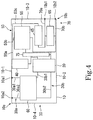
- an AC-DC power supply of a third embodiment illustrated in Fig. 4 includes a DC-DC converter 75.
- the AC-DC power supply of the third embodiment includes a gate driver that drives the switching element 55 and the DC-DC converter 75 that supplies power to the gate driver.
- the DC-DC converter 75 is disposed at right angles to the circuit board 10. This allows suppressing propagation of a noise generated in the DC-DC converter 75 to the circuit board 10 as compared with a case in which the DC-DC converter is disposed parallel to the circuit board.
- the AC-DC power supplies of the first to third embodiments are applicable to motors. Since a motor including the AC-DC power supply according to the first, second, or third embodiment is reduced in electromagnetic noise, the motor has little influence on other electronic devices. For this reason, the motor of the present disclosure can be used in all systems.
Landscapes
- Engineering & Computer Science (AREA)
- Power Engineering (AREA)
- Dc-Dc Converters (AREA)
- Rectifiers (AREA)
Abstract
Description
- The present invention relates to an alternating current (AC) - direct current (DC) power supply and a motor.
- There are known power conversion systems in the related art in which an alternating current is converted to a direct current (for example, Japanese Unexamined Patent Application Publication No.
2015-233375 2015-233375 2015-233375 - PTL 1: Japanese Unexamined Patent Application Publication No.
2015-233375 - In the power conversion system disclosed in Japanese Unexamined Patent Application Publication No.
2015-233375 - In an aspect, the present invention provides an AC-DC power supply which is reduced in size and in which an influence of the switching noise on an alternating-current input line is reduced, as well as a motor.
- According to an aspect of the present invention, an alternating-current (AC) - direct-current (DC) power supply including a circuit board is provided. The circuit board includes an alternating-current input terminal to which an alternating current is input and a direct-current output terminal from which a direct current is output. The AC-DC power supply includes a diode bridge that rectifies the alternating current input via the alternating-current input terminal, an alternating-current input line that electrically connects the alternating-current input terminal and the diode bridge, a coil connected to the diode bridge, a diode connected to the direct-current output terminal, a switching line that electrically connects the coil and the diode, and a switching element connected to the switching line. Part of the switching line is disposed at right angles to part of the alternating-current input line.
- In another aspect of the present invention, a motor including the AC-DC power supply is provided.
- According to an aspect, the present invention provides an AC-DC power supply which is reduced in size and in which an influence of the switching noise on an alternating-current input line is reduced, as well as a motor.
-
-
Fig. 1 is a plan view of an AC-DC power supply of a first embodiment. -
Fig. 2 is a front view of the AC-DC power supply of the first embodiment. -
Fig. 3 is a plan view of an AC-DC power supply of a second embodiment. -
Fig. 4 is a plan view of an AC-DC power supply of a third embodiment. - As illustrated in
Fig. 1 , an AC-DC power supply according to a first embodiment includes acircuit board 10. Thecircuit board 10 includes an alternating-current input terminal 10a to which an alternating current is input. The alternating-current input terminal 10a includes a live or line (L)-side alternating-current input terminal 10a1 and a neutral (N)-side alternating-current input terminal 10a2. Thecircuit board 10 includes a direct-current output terminal 10b from which a direct current is output. The direct-current output terminal 10b includes a high-potential-side direct-current output terminal 10b1 and a low-potential-side direct-current output terminal 10b2. In other words, in the AC-DC power supply of the first embodiment, the alternating-current input terminal 10a and the direct-current output terminal 10b are disposed on thesingle circuit board 10. For this reason, the entire AC-DC power supply can be smaller than that in the case in which the alternating-current input terminal and the direct-current output terminal are not disposed on a single circuit board. - The AC-DC power supply of the first embodiment includes a
diode bridge 20, an alternating-current input line 30, acoil 40, adiode 45, aswitching line 50, and aswitching element 55. Thediode bridge 20 rectifies alternating currents input through the L-side alternating-current input terminal 10a1 and the N-side alternating-current input terminal 10a2 of the alternating-current input terminal 10a. The alternating-current input line 30 electrically connects the alternating-current input terminal 10a and thediode bridge 20. The alternating-current input line 30 includes an alternating-current-input-terminaladjacent portion 30a adjacent to the alternating-current input terminal 10a and a diode-bridgeadjacent portion 30b adjacent to thediode bridge 20. The alternating-current-input-terminaladjacent portion 30a includes an L-side alternating-current-input-terminal adjacent portion 30a1 and an N-side alternating-current-input-terminal adjacent portion 30a2. The diode-bridgeadjacent portion 30b includes an L-side diode-bridge adjacent portion 30b1 and an N-side diode-bridge adjacent portion 30b2. - The alternating-
current input line 30 may be constituted by a land (pattern) formed on thecircuit board 10 or may be constituted by an electronic component mounted on thecircuit board 10. Alternatively, the alternating-current input line 30 may be constituted by a land formed on thecircuit board 10 and an electronic component mounted on thecircuit board 10. - The
coil 40 is connected to thediode bridge 20. Thediode 45 is electrically connected to the direct-current output terminal 10b through a direct-current output line 70. The direct-current output line 70 includes a high-potential-side direct-current output line 70a and a low-potential-side direct-current output line 70b. Acapacitor 65 is disposed on the low-potential-side direct-current output line 70b. The direct-current output line 70 may be constituted by a land (pattern) provided on thecircuit board 10 or may be constituted by an electronic component mounted on thecircuit board 10. Alternatively, the direct-current output line 70 may be constituted by a land provided on thecircuit board 10 and an electronic component mounted on thecircuit board 10. - The
diode 45 is connected to the high-potential-side direct-current output terminal 10b1 through the high-potential-side direct-current output line 70a and is connected to the low-potential-side direct-current output terminal 10b2 through the low-potential-side direct-current output line 70b. Theswitching line 50 electrically connects thecoil 40 and thediode 45. Theswitching element 55 is connected to theswitching line 50. In other words, theswitching line 50 is disposed between thecoil 40, thediode 45, and theswitching element 55. Theswitching line 50 includes a coiladjacent portion 50a adjacent to thecoil 40, a switching elementadjacent portion 50b adjacent to theswitching element 55, and a diodeadjacent portion 50c adjacent to thediode 45. Theswitching line 50 may be constituted by a land provided on thecircuit board 10 or may be constituted by an electronic component mounted on thecircuit board 10. Alternatively, theswitching line 50 may be constituted by a land provided on thecircuit board 10 and an electronic component mounted on thecircuit board 10. - For example, a magnetic field is generated around a portion through which a current flows, such as the
switching line 50. The current flowing through theswitching line 50 fluctuates due to, for example, a switching noise generated in theswitching line 50. This causes the magnetic field generated around theswitching line 50 to fluctuate. If the entire AC-DC power supply is small in size, the magnetic field generated around theswitching line 50 may be applied to the alternating-current input line 30. In the case in which the magnetic field generated around the switchingline 50 is applied to the alternating-current input line 30, fluctuations in the electric current flowing through the switchingline 50 may cause the electric current flowing through the alternating-current input line 30 to fluctuate due to electromagnetic induction. - Specifically, in the case in which the
switching line 50 and the alternating-current input line 30 are parallel to each other, fluctuations in the electric current flowing through the switchingline 50 causes the electric current flowing through the alternating-current input line 30 to fluctuate. In contrast, in the case in which theswitching line 50 and the alternating-current input line 30 are perpendicular to each other, even if the electric current flowing through the switchingline 50 fluctuates, the electric current flowing through the alternating-current input line 30 does not fluctuate due to electromagnetic induction. - Accordingly, in the AC-DC power supply of the first embodiment, part of the
switching line 50 is disposed at right angles to part of the alternating-current input line 30. This allows reducing the influence of the switching noise on the alternating-current input line 30 as compared with a case in which the entire switching line is disposed parallel to the entire alternating-current input line. - Specifically, in the AC-DC power supply of the first embodiment, the coil
adjacent portion 50a is disposed at right angles to the alternating-current-input-terminaladjacent portion 30a. In the example illustrated inFig. 1 , the coiladjacent portion 50a is disposed at right angles to part of the L-side alternating-current-input-terminal adjacent portion 30a1. This allows reducing the influence of the switching noise on the alternating-current-input-terminaladjacent portion 30a of the alternating-current input line 30 as compared with a case in which the coil adjacent portion is disposed parallel to the entire alternating-current-input-terminal adjacent portion. In other words, the AC-DC power supply of the first embodiment can be made compact as a whole and allows reducing the influence of the switching noise on the alternating-current-input-terminaladjacent portion 30a of the alternating-current input line 30. - The
diode bridge 20 is disposed between the alternating-current-input-terminaladjacent portion 30a and the switchingelement 55. In other words, the switchingelement 55 is away from the alternating-current-input-terminaladjacent portion 30a. This allows reducing the influence of the switching noise on the alternating-current-input-terminaladjacent portion 30a as compared with a case in which the switching element is close to the alternating-current-input-terminal adjacent portion. - The AC-DC power supply of the first embodiment further includes an electromagnetic-compatibility (EMC)
countermeasure member 60. TheEMC countermeasure member 60 is disposed in the alternating-current input line 30. Examples of theEMC countermeasure member 60 include an X capacitor, a Y capacitor, a choke coil, and a line filter. The alternating-current-input-terminaladjacent portion 30a connects the alternating-current input terminal 10a and theEMC countermeasure member 60. The diode-bridgeadjacent portion 30b connects the direct-current output terminal 10b and theEMC countermeasure member 60. - In other words, in the AC-DC power supply of the first embodiment, the
EMC countermeasure member 60 is disposed between the switchingline 50 and the alternating-current-input-terminaladjacent portion 30a. This allows reducing the influence of the switching noise on the alternating-current-input-terminaladjacent portion 30a as compared with a case in which no EMC countermeasure member is disposed between the switching line and the alternating-current-input-terminal adjacent portion. - In the example illustrated in
Fig. 1 , the switchingelement 55 is a gallium nitride field-effect transistor. In another example, the switchingelement 55 may be any another switching element. The gallium nitride field-effect transistor is more suitable for high-speed switching than other switching elements and is expected to reduce a loss in power devices. Meanwhile, reduction of switching noise caused by an increased switching frequency is required. - The AC-DC power supply of the first embodiment further includes a gate driver that drives the switching
element 55 and a DC-DC converter 75 that supplies power to the gate driver. As illustrated inFig. 2 , the DC-DC converter 75 is disposed at right angles to thecircuit board 10. This allows suppressing propagation of a noise generated in the DC-DC converter 75 to thecircuit board 10 as compared with a case in which the DC-DC converter is disposed parallel to the circuit board. This also allows suppressing propagation of a noise generated in thecircuit board 10 to the DC-DC converter 75 as compared with a case in which the DC-DC converter is disposed parallel to the circuit board. - In the example illustrated in
Fig. 1 , thecircuit board 10 is rectangular in shape. Thecircuit board 10 includes a first side 10-1, a second side 10-2, a third side 10-3, and a fourth side 10-4. The second side 10-2 is opposite the first side 10-1. The third side 10-3 is disposed at right angles to the first side 10-1. The fourth side 10-4 is opposite the third side 10-3. The alternating-current input terminal 10a is disposed on the first side 10-1. The direct-current output terminal 10b is disposed on the second side 10-2. This allows the alternating-current input terminal 10a and the direct-current output terminal 10b to be disposed away from each other as compared with a case in which the alternating-current input terminal and the direct-current output terminal are disposed on the same side. This allows reducing an influence of the noise generated in the vicinity of the direct-current output terminal 10b on the alternating-current-input-terminaladjacent portion 30a. - In an AC-DC power supply of a second embodiment illustrated in
Fig. 3 , the positions of the alternating-current input terminal 10a and the direct-current output terminal 10b of thecircuit board 10 differs from those of the AC-DC power supply of the first embodiment illustrated inFig. 1 . - In the AC-DC power supply of the second embodiment illustrated in
Fig. 3 , the positions of thediode bridge 20, thecoil 40, thediode 45, the switchingelement 55, thecapacitor 65, and theEMC countermeasure member 60 mounted on thecircuit board 10 differ from those of the AC-DC power supply of the first embodiment illustrated inFig. 1 . Furthermore, in the AC-DC power supply of the second embodiment illustrated inFig. 3 , the positions of the alternating-current input line 30, the switchingline 50, and the direct-current output line 70 mounted on thecircuit board 10 differ from those of the AC-DC power supply of the first embodiment illustrated inFig. 1 . - Also in the AC-DC power supply of the second embodiment, part of the
switching line 50 is disposed at right angles to part of the alternating-current input line 30, as illustrated inFig. 3 . This allows reducing the influence of the switching noise on the alternating-current input line 30 as compared with a case in which the entire switching line is disposed parallel to the entire alternating-current input line. - Specifically, in the AC-DC power supply of the second embodiment, the coil
adjacent portion 50a is disposed at right angles to the alternating-current-input-terminaladjacent portion 30a. In the example illustrated inFig. 3 , the coiladjacent portion 50a is disposed at right angles to the L-side alternating-current-input-terminal adjacent portion 30a1 and the N-side alternating-current-input-terminal adjacent portion 30a2. This allows reducing the influence of the switching noise on the alternating-current-input-terminaladjacent portion 30a of the alternating-current input line 30 as compared with a case in which the coil adjacent portion is disposed parallel to the alternating-current-input-terminal adjacent portion. In other words, the AC-DC power supply of the second embodiment can be made compact as a whole and allows reducing the influence of the switching noise on the alternating-current-input-terminaladjacent portion 30a of the alternating-current input line 30. - As illustrated in
Fig. 3 , thediode bridge 20 is disposed between the alternating-current-input-terminaladjacent portion 30a and the switchingelement 55. In other words, the switchingelement 55 is disposed away from the alternating-current-input-terminaladjacent portion 30a in the lateral direction inFig. 3 . This allows reducing the influence of the switching noise on the alternating-current-input-terminaladjacent portion 30a as compared with a case in which the switching element is close to the alternating-current-input-terminal adjacent portion. - As illustrated in
Fig. 3 , also in the AC-DC power supply of the second embodiment, theEMC countermeasure member 60 is disposed between the switchingline 50 and the alternating-current-input-terminaladjacent portion 30a. This allows reducing the influence of the switching noise on the alternating-current-input-terminaladjacent portion 30a as compared with a case in which no EMC countermeasure member is disposed between the switching line and the alternating-current-input-terminal adjacent portion. - In the AC-DC power supply of the second embodiment illustrated in
Fig. 3 , thecircuit board 10 is rectangular in shape as that of the AC-DC power supply of the first embodiment illustrated inFig. 1 . In the AC-DC power supply of the second embodiment, the direct-current output line 70 is disposed at right angles to the alternating-current-input-terminaladjacent portion 30a. This allows reducing the influence of the noise generated in the direct-current output line 70 on the alternating-current-input-terminaladjacent portion 30a as compared with a case in which the direct-current output line is disposed parallel to the alternating-current-input-terminal adjacent portion. - In the AC-DC power supply of the second embodiment, the
coil 40 is disposed between the alternating-current-input-terminaladjacent portion 30a and the switchingelement 55 as illustrated inFig. 3 . A first direction (the lateral direction inFig. 3 ) in which the coiladjacent portion 50a extends is perpendicular to a second direction (the vertical direction inFig. 3 ) in which the alternating-current-input-terminaladjacent portion 30a extends. A distance a between thecoil 40 and the switchingelement 55 in the first direction is larger than a distance b between the switchingelement 55 and thediode 45 in the second direction. In other words, the switchingelement 55 is away from the alternating-current-input-terminaladjacent portion 30a. This allows reducing the influence of the switching noise on the alternating-current-input-terminaladjacent portion 30a as compared with a case in which the switching element is close to the alternating-current-input-terminal adjacent portion. - In the AC-DC power supply of the second embodiment, part of the diode-bridge
adjacent portion 30b is parallel to the coiladjacent portion 50a, as illustrated inFig. 3 . In other words, the L-side diode-bridge adjacent portion 30b1 and the N-side diode-bridge adjacent portion 30b2 each have a portion parallel to the coiladjacent portion 50a and a portion perpendicular to the coiladjacent portion 50a. The length d of the portion of the L-side diode-bridge adjacent portion 30b1 parallel to the coiladjacent portion 50a is smaller than the length c of the alternating-current-input-terminaladjacent portion 30a. - In other words, in the AC-DC power supply of the second embodiment, the influence of the switching noise on the L-side diode-bridge adjacent portion 30b1 can be reduced as compared with a case in which the length d of the portion of the L-side diode-bridge adjacent portion 30b1 parallel to the coil
adjacent portion 50a is larger than the length c of the alternating-current-input-terminaladjacent portion 30a perpendicular to the coiladjacent portion 50a. - While the AC-DC power supply of the second embodiment illustrated in
Fig. 3 includes no DC-DC converter, an AC-DC power supply of a third embodiment illustrated inFig. 4 includes a DC-DC converter 75. Specifically, the AC-DC power supply of the third embodiment includes a gate driver that drives the switchingelement 55 and the DC-DC converter 75 that supplies power to the gate driver. The DC-DC converter 75 is disposed at right angles to thecircuit board 10. This allows suppressing propagation of a noise generated in the DC-DC converter 75 to thecircuit board 10 as compared with a case in which the DC-DC converter is disposed parallel to the circuit board. This also suppressing propagation of a noise generated in thecircuit board 10 to the DC-DC converter 75 as compared with a case in which the DC-DC converter is disposed parallel to the circuit board. The AC-DC power supplies of the first to third embodiments are applicable to motors. Since a motor including the AC-DC power supply according to the first, second, or third embodiment is reduced in electromagnetic noise, the motor has little influence on other electronic devices. For this reason, the motor of the present disclosure can be used in all systems. -
- 10 CIRCUIT BOARD
- 10a ALTERNATING-CURRENT INPUT TERMINAL
- 10a1 L-SIDE ALTERNATING-CURRENT INPUT TERMINAL
- 10a2 N-SIDE ALTERNATING-CURRENT INPUT TERMINAL
- 10b DIRECT-CURRENT OUTPUT TERMINAL
- 10b1 HIGH-POTENTIAL-SIDE DIRECT-CURRENT OUTPUT TERMINAL
- 10b2 LOW-POTENTIAL-SIDE DIRECT-CURRENT OUTPUT TERMINAL
- 10-1, 10-2, 10-3, 10-4 SIDE
- 20 DIODE BRIDGE
- 30 ALTERNATING-CURRENT INPUT LINE
- 30a ALTERNATING-CURRENT-INPUT-TERMINAL ADJACENT PORTION
- 30a1 L-SIDE ALTERNATING-CURRENT-INPUT-TERMINAL ADJACENT PORTION
- 30a2 N-SIDE ALTERNATING-CURRENT-INPUT-TERMINAL ADJACENT PORTION
- 30b DIODE-BRIDGE ADJACENT PORTION
- 30b1 L-SIDE DIODE-BRIDGE ADJACENT PORTION
- 30b2 N-SIDE DIODE-BRIDGE ADJACENT PORTION
- 40 COIL
- 45 DIODE
- 50 SWITCHING LINE
- 50a COIL ADJACENT PORTION
- 50b SWITCHING ELEMENT ADJACENT PORTION
- 50c DIODE ADJACENT PORTION
- 55 SWITCHING ELEMENT
- 60 EMC COUNTERMEASURE MEMBER
- 65 CAPACITOR
- 70 DIRECT-CURRENT OUTPUT LINE
- 70a HIGH-POTENTIAL-SIDE DIRECT-CURRENT OUTPUT LINE
- 70b LOW-POTENTIAL-SIDE DIRECT-CURRENT OUTPUT LINE
- 75 DC-DC CONVERTER
Claims (12)
- An alternating-current (AC) - direct-current (DC) power supply comprising:a circuit board,wherein the circuit board comprises:an alternating-current input terminal to which an alternating current is input; anda direct-current output terminal from which a direct current is output, andwherein the AC-DC power supply comprises:a diode bridge that rectifies the alternating current input via the alternating-current input terminal;an alternating-current input line that electrically connects the alternating-current input terminal and the diode bridge;a coil connected to the diode bridge;a diode connected to the direct-current output terminal;a switching line that electrically connects the coil and the diode; anda switching element connected to the switching line,wherein part of the switching line is disposed at right angles to part of the alternating-current input line.
- The AC-DC power supply according to Claim 1,
wherein the switching line includes a coil adjacent portion adjacent to the coil,
wherein the alternating-current input line includes an alternating-current-input-terminal adjacent portion adjacent to the alternating-current input terminal, and
wherein the coil adjacent portion is disposed at right angles to the alternating-current-input-terminal adjacent portion. - The AC-DC power supply according to Claim 2,
wherein the diode bridge is disposed between the alternating-current-input-terminal adjacent portion and the switching element. - The AC-DC power supply according to Claim 2 or 3, further comprising:an electromagnetic-compatibility (EMC) countermeasure member,wherein the EMC countermeasure member is disposed in the alternating-current input line, andwherein the alternating-current-input-terminal adjacent portion connects the alternating-current input terminal and the EMC countermeasure member.
- The AC-DC power supply according to any one of Claims 2 to 4,
wherein the coil is disposed between the alternating-current-input-terminal adjacent portion and the switching element. - The AC-DC power supply according to Claim 5,
wherein a first direction in which the coil adjacent portion extends is perpendicular to a second direction in which the alternating-current-input-terminal adjacent portion extends, and
wherein a distance between the coil and the switching element in the first direction is larger than a distance between the switching element and the diode in the second direction. - The AC-DC power supply according to any one of Claims 2 to 6,
wherein the alternating-current input line includes a diode-bridge adjacent portion adjacent to the diode bridge,
wherein the diode-bridge adjacent portion is parallel to the coil adjacent portion, and
wherein the diode-bridge adjacent portion is shorter than the alternating-current-input-terminal adjacent portion. - The AC-DC power supply according to any one of Claims 2 to 7, further comprising:a direct-current output line that electrically connects the direct-current output terminal and the diode,wherein the direct-current output line is disposed at right angles to the alternating-current-input-terminal adjacent portion.
- The AC-DC power supply according to any one of Claims 1 to 7,
wherein the circuit board is rectangular in shape,
wherein the alternating-current input terminal is disposed on a first side of the circuit board, and
wherein the direct-current output terminal is disposed on a second side that is opposite the first side. - The AC-DC power supply according to any one of Claims 1 to 9,
wherein the switching element is a gallium nitride field-effect transistor. - The AC-DC power supply according to any one of Claims 1 to 10, further comprising:a gate driver that drives the switching element; anda DC-DC converter that supplies power to the gate driver,wherein the DC-DC converter is disposed at right angles to the circuit board.
- A motor comprising:
the AC-DC power supply according to any one of Claims 1 to 11.
Applications Claiming Priority (2)
| Application Number | Priority Date | Filing Date | Title |
|---|---|---|---|
| JP2016221689 | 2016-11-14 | ||
| PCT/JP2017/040347 WO2018088454A1 (en) | 2016-11-14 | 2017-11-09 | Ac-dc power supply device and motor |
Publications (2)
| Publication Number | Publication Date |
|---|---|
| EP3540930A1 true EP3540930A1 (en) | 2019-09-18 |
| EP3540930A4 EP3540930A4 (en) | 2020-06-24 |
Family
ID=62109176
Family Applications (1)
| Application Number | Title | Priority Date | Filing Date |
|---|---|---|---|
| EP17870103.3A Withdrawn EP3540930A4 (en) | 2016-11-14 | 2017-11-09 | Ac-dc power supply device and motor |
Country Status (5)
| Country | Link |
|---|---|
| US (1) | US11271489B2 (en) |
| EP (1) | EP3540930A4 (en) |
| JP (1) | JPWO2018088454A1 (en) |
| CN (1) | CN109952700A (en) |
| WO (1) | WO2018088454A1 (en) |
Family Cites Families (11)
| Publication number | Priority date | Publication date | Assignee | Title |
|---|---|---|---|---|
| JPH07288978A (en) | 1994-04-18 | 1995-10-31 | Matsushita Electric Works Ltd | Switching power supply |
| JP3239082B2 (en) | 1997-04-23 | 2001-12-17 | 三洋電機株式会社 | Hybrid integrated circuit device |
| JP2005198385A (en) * | 2004-01-06 | 2005-07-21 | Muscle Corp | Driving device of motor and method of controlling the same |
| CN2733737Y (en) * | 2004-05-12 | 2005-10-12 | 郑春江 | AC/DC power adapter |
| JP5423264B2 (en) | 2009-09-11 | 2014-02-19 | 富士電機株式会社 | Power converter |
| EP2590311A4 (en) * | 2010-09-29 | 2014-04-23 | Panasonic Corp | POWER CONVERTER APPARATUS |
| JP5530401B2 (en) * | 2011-05-26 | 2014-06-25 | 株式会社日立情報通信エンジニアリング | Power supply |
| JP2014171316A (en) * | 2013-03-04 | 2014-09-18 | Mitsubishi Electric Corp | Semiconductor module and boosting rectification circuit |
| JP6233568B2 (en) * | 2013-09-27 | 2017-11-22 | 東芝ライテック株式会社 | Power supply circuit and lighting device |
| JP2015233375A (en) | 2014-06-10 | 2015-12-24 | 日立アプライアンス株式会社 | Power factor improvement module and power conversion device employing the same |
| JP6150086B2 (en) | 2016-03-23 | 2017-06-21 | 東芝ライテック株式会社 | Power factor correction circuit and power supply device |
-
2017
- 2017-11-09 CN CN201780069056.4A patent/CN109952700A/en not_active Withdrawn
- 2017-11-09 EP EP17870103.3A patent/EP3540930A4/en not_active Withdrawn
- 2017-11-09 US US16/344,370 patent/US11271489B2/en active Active
- 2017-11-09 WO PCT/JP2017/040347 patent/WO2018088454A1/en not_active Ceased
- 2017-11-09 JP JP2018550240A patent/JPWO2018088454A1/en active Pending
Also Published As
| Publication number | Publication date |
|---|---|
| EP3540930A4 (en) | 2020-06-24 |
| CN109952700A (en) | 2019-06-28 |
| WO2018088454A1 (en) | 2018-05-17 |
| US11271489B2 (en) | 2022-03-08 |
| JPWO2018088454A1 (en) | 2019-10-03 |
| US20210288587A1 (en) | 2021-09-16 |
Similar Documents
| Publication | Publication Date | Title |
|---|---|---|
| CN107306515B (en) | Electric circuit device | |
| JP4668301B2 (en) | Power converter | |
| EP3664274A1 (en) | Power conversion device and vehicle equipped with power conversion device | |
| EP2928057A1 (en) | Power converting device and railway vehicle mounted with the same | |
| US20180263110A1 (en) | Printed circuit board and switching power supply employing it | |
| Di Capua et al. | Power magnetics volume and weight reduction in aerospace power supply units | |
| CN103856068B (en) | Power-converting device | |
| US9960688B2 (en) | DC power supply with multi-cell converter | |
| EP2740208B2 (en) | Electronic device, in particular transmitter head, and system for wireless energy transfer | |
| US11271489B2 (en) | AC-DC power supply and motor | |
| CN112913132B (en) | Power conversion device | |
| CN107624216B (en) | Power electronic equipment | |
| US20190081555A1 (en) | Electrical circuit device | |
| CN110121834B (en) | Power conversion device | |
| EP2643913B1 (en) | Power supply arrangement for distribution of power | |
| US10225935B2 (en) | Power conversion device | |
| US10375821B2 (en) | Converter mounting board | |
| US6633493B2 (en) | Inherently short-circuit resistant power distribution system | |
| US10257922B2 (en) | Method for reducing conductor track spacing in electronic circuit boards and electronic circuit board with reduced spacing between conductor tracks | |
| US20180190431A1 (en) | Electronic device | |
| US9584010B2 (en) | Power supply apparatus | |
| EP4429096A1 (en) | Power conversion device | |
| US11373799B2 (en) | Choke coil | |
| US9330826B1 (en) | Integrated architecture for power converters | |
| Hegarty | Valuing wide VIN, low EMI synchronous buck circuits for cost-driven, demanding applications |
Legal Events
| Date | Code | Title | Description |
|---|---|---|---|
| STAA | Information on the status of an ep patent application or granted ep patent |
Free format text: STATUS: THE INTERNATIONAL PUBLICATION HAS BEEN MADE |
|
| PUAI | Public reference made under article 153(3) epc to a published international application that has entered the european phase |
Free format text: ORIGINAL CODE: 0009012 |
|
| STAA | Information on the status of an ep patent application or granted ep patent |
Free format text: STATUS: REQUEST FOR EXAMINATION WAS MADE |
|
| 17P | Request for examination filed |
Effective date: 20190426 |
|
| AK | Designated contracting states |
Kind code of ref document: A1 Designated state(s): AL AT BE BG CH CY CZ DE DK EE ES FI FR GB GR HR HU IE IS IT LI LT LU LV MC MK MT NL NO PL PT RO RS SE SI SK SM TR |
|
| AX | Request for extension of the european patent |
Extension state: BA ME |
|
| DAV | Request for validation of the european patent (deleted) | ||
| DAX | Request for extension of the european patent (deleted) | ||
| A4 | Supplementary search report drawn up and despatched |
Effective date: 20200527 |
|
| RIC1 | Information provided on ipc code assigned before grant |
Ipc: H02M 7/00 20060101ALI20200519BHEP Ipc: H02P 29/50 20160101ALI20200519BHEP Ipc: H02M 1/00 20060101ALI20200519BHEP Ipc: H02M 1/42 20070101AFI20200519BHEP |
|
| STAA | Information on the status of an ep patent application or granted ep patent |
Free format text: STATUS: THE APPLICATION IS DEEMED TO BE WITHDRAWN |
|
| 18D | Application deemed to be withdrawn |
Effective date: 20210112 |