EP3540907A1 - Control device, control method, and program - Google Patents
Control device, control method, and program Download PDFInfo
- Publication number
- EP3540907A1 EP3540907A1 EP17869307.3A EP17869307A EP3540907A1 EP 3540907 A1 EP3540907 A1 EP 3540907A1 EP 17869307 A EP17869307 A EP 17869307A EP 3540907 A1 EP3540907 A1 EP 3540907A1
- Authority
- EP
- European Patent Office
- Prior art keywords
- secondary battery
- charging
- lithium ion
- ion secondary
- voltage
- Prior art date
- Legal status (The legal status is an assumption and is not a legal conclusion. Google has not performed a legal analysis and makes no representation as to the accuracy of the status listed.)
- Granted
Links
Images



Classifications
-
- H—ELECTRICITY
- H01—ELECTRIC ELEMENTS
- H01M—PROCESSES OR MEANS, e.g. BATTERIES, FOR THE DIRECT CONVERSION OF CHEMICAL ENERGY INTO ELECTRICAL ENERGY
- H01M10/00—Secondary cells; Manufacture thereof
- H01M10/42—Methods or arrangements for servicing or maintenance of secondary cells or secondary half-cells
- H01M10/44—Methods for charging or discharging
- H01M10/448—End of discharge regulating measures
-
- H—ELECTRICITY
- H02—GENERATION; CONVERSION OR DISTRIBUTION OF ELECTRIC POWER
- H02J—ELECTRIC POWER NETWORKS; CIRCUIT ARRANGEMENTS OR SYSTEMS FOR SUPPLYING OR DISTRIBUTING ELECTRIC POWER; SYSTEMS FOR STORING ELECTRIC ENERGY
- H02J7/00—Circuit arrangements for charging or discharging batteries or for supplying loads from batteries
- H02J7/90—Regulation of charging or discharging current or voltage
- H02J7/96—Regulation of charging or discharging current or voltage in response to battery voltage
-
- H—ELECTRICITY
- H01—ELECTRIC ELEMENTS
- H01M—PROCESSES OR MEANS, e.g. BATTERIES, FOR THE DIRECT CONVERSION OF CHEMICAL ENERGY INTO ELECTRICAL ENERGY
- H01M10/00—Secondary cells; Manufacture thereof
- H01M10/42—Methods or arrangements for servicing or maintenance of secondary cells or secondary half-cells
- H01M10/4285—Testing apparatus
-
- H—ELECTRICITY
- H01—ELECTRIC ELEMENTS
- H01M—PROCESSES OR MEANS, e.g. BATTERIES, FOR THE DIRECT CONVERSION OF CHEMICAL ENERGY INTO ELECTRICAL ENERGY
- H01M10/00—Secondary cells; Manufacture thereof
- H01M10/42—Methods or arrangements for servicing or maintenance of secondary cells or secondary half-cells
- H01M10/44—Methods for charging or discharging
-
- H—ELECTRICITY
- H01—ELECTRIC ELEMENTS
- H01M—PROCESSES OR MEANS, e.g. BATTERIES, FOR THE DIRECT CONVERSION OF CHEMICAL ENERGY INTO ELECTRICAL ENERGY
- H01M10/00—Secondary cells; Manufacture thereof
- H01M10/42—Methods or arrangements for servicing or maintenance of secondary cells or secondary half-cells
- H01M10/48—Accumulators combined with arrangements for measuring, testing or indicating the condition of cells, e.g. the level or density of the electrolyte
-
- Y—GENERAL TAGGING OF NEW TECHNOLOGICAL DEVELOPMENTS; GENERAL TAGGING OF CROSS-SECTIONAL TECHNOLOGIES SPANNING OVER SEVERAL SECTIONS OF THE IPC; TECHNICAL SUBJECTS COVERED BY FORMER USPC CROSS-REFERENCE ART COLLECTIONS [XRACs] AND DIGESTS
- Y02—TECHNOLOGIES OR APPLICATIONS FOR MITIGATION OR ADAPTATION AGAINST CLIMATE CHANGE
- Y02E—REDUCTION OF GREENHOUSE GAS [GHG] EMISSIONS, RELATED TO ENERGY GENERATION, TRANSMISSION OR DISTRIBUTION
- Y02E60/00—Enabling technologies; Technologies with a potential or indirect contribution to GHG emissions mitigation
- Y02E60/10—Energy storage using batteries
Definitions
- the present invention relates to charging of a secondary battery.
- a lithium ion secondary battery As one of secondary batteries, a lithium ion secondary battery is used. When the lithium ion secondary battery is used, there is a need to charge the lithium ion secondary battery using a charging apparatus.
- Patent Document 1 disclosed a technology of measuring a terminal voltage of a secondary battery at each suspension time in an intermittent charging operation, computing a parameter which represents a charged state of the secondary battery from the measured terminal voltage, and lowering a charging electrical current based on the parameter.
- Patent Document 2 disclosed a technology of determining when to start charging of a lithium ion secondary battery, based on a change ratio of an open circuit voltage (OCV) of the lithium ion secondary battery, after discharging of the lithium ion secondary battery.
- OCV open circuit voltage
- Patent Document 3 discloses a technology of performing improvement of a charging cycle, by providing suspension in charging when the charging of a nonaqueous electrolyte secondary battery is first performed.
- the present inventors find out a new charging method of a lithium ion battery.
- An object of the present invention is to provide the new charging method of the lithium ion battery.
- a first control apparatus of the present invention includes a control unit that controls a charging apparatus which performs charging of a lithium ion secondary battery.
- the control unit (1) causes the charging apparatus to perform the charging of the lithium ion secondary battery, until a voltage of the lithium ion secondary battery becomes a predetermined voltage, (2) causes the charging apparatus to suspend the charging of the lithium ion secondary battery, until a predetermined time t elapses, after the charging, and (3) causes the charging apparatus to further perform the charging of the lithium ion secondary battery, after the suspending.
- the predetermined time t [minute] satisfies a condition that is determined by Expression (1) using weight per unit area x [g/cm 2 ] of a negative electrode of the lithium ion secondary battery and density y [g/cm 3 ] of the negative electrode.
- Expression 1 t ⁇ ⁇ A + B ⁇ x + C ⁇ y 50 ⁇ A ⁇ 70 , 500 ⁇ B ⁇ 620 , 30 ⁇ C ⁇ 36
- a second control apparatus of the present invention includes a control unit that controls a charging apparatus which performs charging of a lithium ion secondary battery.
- the control unit (1) causes the charging apparatus to perform the charging of the lithium ion secondary battery, until a voltage of the lithium ion secondary battery becomes a predetermined voltage, (2) causes the charging apparatus to suspend the charging of the lithium ion secondary battery, until a predetermined time t elapses, after the charging, and (3) causes the charging apparatus to further perform the charging of the lithium ion secondary battery, after the suspending.
- the predetermined time is a length that is equal to or more than time from a time point at which the suspending is started to a time point at which a temporal change ratio of the voltage of the lithium ion secondary battery becomes a local minimum value.
- a first control method of the present invention includes (1) a step of causing a charging apparatus that performs charging of a lithium ion secondary battery to perform the charging of the lithium ion secondary battery, until a voltage of the lithium ion secondary battery becomes a predetermined voltage, (2) a step of causing the charging apparatus to suspend the charging of the lithium ion secondary battery, until a predetermined time t elapses, after the charging, and (3) a step of causing the charging apparatus to further perform the charging of the lithium ion secondary battery, after the suspending.
- the predetermined time t [minute] satisfies a condition that is determined by Expression (2) using weight per unit area x [g/cm 2 ] of a negative electrode of the lithium ion secondary battery and density y [g/cm 3 ] of the negative electrode.
- Expression 3 t ⁇ ⁇ A + B ⁇ x + C ⁇ y 50 ⁇ A ⁇ 70 , 500 ⁇ B ⁇ 620 , 30 ⁇ C ⁇ 36
- a second control method of the present invention includes (1) a step of causing a charging apparatus that performs charging of a lithium ion secondary battery to perform the charging of the lithium ion secondary battery, until a voltage of the lithium ion secondary battery becomes a predetermined voltage, (2) a step of causing the charging apparatus to suspend the charging of the lithium ion secondary battery, until a predetermined time t elapses, after the charging, and (3) a step of causing the charging apparatus to further perform the charging of the lithium ion secondary battery, after the suspending.
- the predetermined time is a length that is equal to or more than time from a time point at which the suspending is started to a time point at which a temporal change ratio of the voltage of the lithium ion secondary battery becomes a local minimum value.
- a program of the present invention causes a computer to execute each step of the first control method or the second control method of the present invention.
- a new charging method of a lithium ion battery is provided.
- each block in a block diagram is not a configuration of a hardware unit but a configuration of a functional unit.
- Fig. 1 is a block diagram illustrating a control apparatus 2000 according to Example Embodiment 1 along with a usage environment thereof.
- a charging apparatus 20 is an apparatus that performs charging of a lithium ion secondary battery 10.
- the control apparatus 2000 includes a control unit 2020.
- the control unit 2020 causes the charging apparatus 20 to charge the lithium ion secondary battery 10, by controlling the charging apparatus 20. At that time, the control unit 2020 controls the charging apparatus 20 as described below.
- the control unit 2020 causes the charging apparatus 20 to charge the lithium ion secondary battery 10, until a voltage of the lithium ion secondary battery 10 becomes a predetermined voltage. Thereafter, the control unit 2020 causes the charging apparatus 20 to suspend the charging of the lithium ion secondary battery 10, until a predetermined time elapses. The control unit 2020 causes the charging apparatus 20 to further perform the charging of the lithium ion secondary battery 10, after the suspension.
- Fig. 2 is a diagram illustrating a transition of the voltage, regarding the lithium ion secondary battery 10 charged by the charging apparatus 20 that is controlled by the control apparatus 2000.
- a voltage Va is the predetermined voltage described above.
- the control unit 2020 causes the charging apparatus 20 to perform the charging of the lithium ion secondary battery 10, until the voltage of the lithium ion secondary battery 10 becomes Va. As a result, the voltage of the lithium ion secondary battery 10 becomes Va at a time point Ta.
- control unit 2020 causes the charging of the lithium ion secondary battery 10 to be suspended, until a predetermined suspension time t elapses.
- suspension time the time during which the charging of the lithium ion secondary battery 10 is suspended.
- the control unit 2020 causes the charging apparatus 20 to further perform the charging of the lithium ion secondary battery 10, from a time point Tb.
- the time point Tb is a point of time at which the suspension time t elapses from the time point Ta.
- the suspension time t satisfies a condition of Expression (3) below.
- Expression 3 t ⁇ ⁇ A + B ⁇ x + C ⁇ y 50 ⁇ A ⁇ 70 , 500 ⁇ B ⁇ 620 , 30 ⁇ C ⁇ 36 x represents weight per unit area of a negative electrode of the lithium ion secondary battery 10.
- the unit thereof is g/cm 2 .
- y is density of the negative electrode.
- the unit thereof is g/cm 3 .
- the unit of t is minute.
- A, B, and C are respectively constants.
- the suspension time t may be set as 0.
- the control apparatus 2000 may cause the charging of the lithium ion secondary battery 10 not to be suspended.
- the present inventors found out that lithium deposits on a surface of the negative electrode of the lithium ion secondary battery 10 during the charging of the lithium ion secondary battery 10. For example, a cause of this phenomenon is considered as follows.
- Figs. 3 are diagram illustrating a state of the negative electrode of the lithium ion secondary battery 10 at the time of charging the lithium ion secondary battery 10.
- Fig. 3A illustrates the state of the negative electrode of the lithium ion secondary battery 10 before a start of the charging.
- the negative electrode of the lithium ion secondary battery 10 is configured by combining an active material 50 with a current collector 60.
- a main component of the active material 50 is graphite.
- Fig. 3B illustrates the state of the negative electrode of the lithium ion secondary battery 10 after the start of the charging.
- Fig. 3C illustrates the state in which lithium deposits on the surface of the active material 50.
- the control apparatus 2000 of the present example embodiment suspends the charging for a predetermined time.
- the lithium ions which are incorporated into the active material 50 are unevenly distributed in the active material 50, as the lithium ion secondary battery 10 is charged up to the predetermined voltage ( Fig. 3B ).
- the lithium ions are dispersed in the active material 50 in the meanwhile. Accordingly, even if the charging of the lithium ion secondary battery 10 is further performed after the suspension, the deposition of lithium due to the unevenness of the distribution of the lithium ions is less likely to be caused.
- control apparatus 2000 of the present example embodiment it is possible to charge the lithium ion secondary battery 10, while preventing the deposition of lithium from the negative electrode of the lithium ion secondary battery 10.
- control apparatus 2000 of the present example embodiment it is possible to prevent the deposition of lithium on the negative electrode, without lowering the density of the negative electrode. Accordingly, it is possible to raise the volume energy density of the lithium ion secondary battery 10.
- Each functional configuration unit of the control apparatus 2000 may be realized by hardware (example: hard-wired electronic circuit or the like) that realizes each functional configuration unit, or may be realized by a combination (example: combination of an electronic circuit with a program for controlling the same, or the like) of hardware with software.
- hardware example: hard-wired electronic circuit or the like
- combination example: combination of an electronic circuit with a program for controlling the same, or the like
- each functional configuration unit of the control apparatus 2000 is realized by the combination of the hardware with the software will be further described.
- Fig. 4 is a diagram illustrating a computer 1000 for realizing the control apparatus 2000.
- the computer 1000 is any computer.
- the computer 1000 is a micro control unit (MCU), a personal computer (PC), a server machine, or the like.
- the computer 1000 may be an exclusive-use computer that is designed in order to realize the control apparatus 2000, or may be a general-purpose computer.
- the computer 1000 includes a bus 1020, a processor 1040, a memory 1060, a storage device 1080, and an input-output interface 1100.
- the bus 1020 is a data transmission channel for sending and receiving data to each other in the processor 1040, the memory 1060, the storage device 1080, and the input-output interface 1100.
- a method of connecting the processors 1040 and the like to each other is not limited to the bus connection.
- the processor 1040 is an arithmetic processing apparatus such as a microprocessor or a central processing unit (CPU).
- the memory 1060 is a memory such as a random access memory (RAM).
- the storage device 1080 is a storing apparatus such as a read only memory (ROM), a flash memory, or a hard disk.
- the input-output interface 1100 is an interface for connecting the computer 1000 to an input-output device.
- Fig. 5 is a flowchart illustrating a flow of processing that is executed by the control apparatus 2000 according to Example Embodiment 1.
- the control unit 2020 controls the charging apparatus 20, and causes the lithium ion secondary battery 10 to be charged up to the predetermined voltage (S102).
- the control unit 2020 controls the charging apparatus 20, and causes the charging of the lithium ion secondary battery 10 to be suspended for the predetermined time (S104). After S104, the control unit 2020 controls the charging apparatus 20, and causes the lithium ion secondary battery 10 to be further charged (S106).
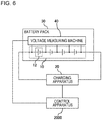
- Fig. 6 is a diagram further specifically illustrating a usage environment of the control apparatus 2000.
- the lithium ion secondary battery 10 is configured as an assembled battery in which a plurality of unit battery cells 12 are connected in series.
- the charging apparatus 20 is connected to the lithium ion secondary battery 10.
- the lithium ion secondary battery 10 is included in a battery pack 30. Furthermore, the battery pack 30 includes a voltage measuring machine 40 that measures the voltage of the lithium ion secondary battery 10.
- the control apparatus 2000 is connected to the voltage measuring machine 40 which is included in the battery pack 30.
- the control apparatus 2000 repeatedly obtains the voltage of the lithium ion secondary battery 10, from the voltage measuring machine 40. By doing so, it is recognized that the voltage of the lithium ion secondary battery 10 becomes the predetermined voltage by the control apparatus 2000. Furthermore, the control apparatus 2000 is connected to the charging apparatus 20.
- control apparatus 2000 is not limited to an example illustrated in Fig. 5 .
- control apparatus 2000 may be provided on the inside of the charging apparatus 20.
- the lithium ion secondary battery 10 is necessarily configured as an assembled battery.
- the components of a positive electrode terminal and a negative electrode terminal of the lithium ion secondary battery 10 are optional.
- the positive electrode terminal of the lithium ion secondary battery 10 is a terminal using a nickel-based positive electrode material as an active material.
- the negative electrode terminal of the lithium ion secondary battery 10 is a terminal using a material whose main component is graphite as an active material.
- the suspension time t representing a length of the suspension time is represented by Expression (3).
- a method for introducing a range of each parameter A to C in Expression (3) will be described.
- the range of a value of each parameter described above is introduced by a test described below.
- the battery cells of a plurality of patterns whose the weight per unit area of the negative electrode and the density of the negative electrode are different from each other are used.
- CCCV charging constant current and constant voltage charging
- the charging is suspended for the predetermined time, in each of a time point at which the charging voltage is 4.0 V and a time point at which the charging voltage is 4.1 V.
- the test is performed onto each of cases where the suspension time are 1 minute, 3 minutes, and 5 minutes. The test is performed onto a case where the suspension is not performed as well.
- the cell after the charging is discharged (0.2 C, 2.5 V)
- the cell is disassembled, and the surface of the negative electrode is visually observed.
- deposition with white color is perceived on the surface of the negative electrode
- it is determined that lithium had deposited it is determined that lithium had not deposited (the lithium deposition is prevented).
- Table 1 to Table 3 hereinafter are tables illustrating test results.
- [Table 1] Suspension time/density of negative electrode 1.55 1.5 1.46 1.4 0 x ⁇ 1 x ⁇ 3 x ⁇ 5 ⁇ 10
- Table 1 illustrates a test result of a case where the weight per unit area of the negative electrode is 0.024 g/cm.
- Table 2 Suspension time/density of negative electrode 1.55 1.5 1.46 1.4 0 x ⁇ ⁇ 1 x ⁇ 3 ⁇ 5 10
- Table 2 illustrates a test result of a case where the weight per unit area of the negative electrode is 0.021 g/cm.
- [Table 3] Suspension time/density of negative electrode 1.55 1.5 1.46 1.4 0 x ⁇ ⁇ ⁇ 1 ⁇ 3 5 10
- Table 3 illustrates a test result of a case where the weight per unit area of the negative electrode is 0.018 g/cm 2 .
- lithium is likely to deposit on the negative electrode as the weight per unit area of the negative electrode is large, and lithium is likely to deposit on the negative electrode as the density of the negative electrode is high.
- an upper limit value of the range of A, an upper limit value of the range of B, and an upper limit value of the range of C are 65, 590, and 34, respectively.
- a lower limit value of the range of A, a lower limit value of the range of B, and a lower limit value of the range of C are 55, 530, and 32, respectively.
- the control unit 2020 causes the charging apparatus 20 to perform the charging of the lithium ion secondary battery 10, until the voltage of the lithium ion secondary battery 10 becomes the predetermined voltage (S102).
- the predetermined voltage is a voltage with which a state of charge (SOC) of the lithium ion secondary battery 10 is equal to or more than 70% and equal to or less than 100% in a case where the lithium ion secondary battery 10 is charged at the charging rate of 0.2 C.
- the lower limit value of the range of the predetermined voltage is 75% of the SOC of the lithium ion secondary battery 10 by the charging described above.
- the further suitable lower limit value is 80% of the SOC of the lithium ion secondary battery 10 by the same charging.
- the upper limit value of the range of the predetermined voltage is 95% of the SOC of the lithium ion secondary battery 10 by the same charging.
- the further suitable upper limit value is 90% of the SOC of the lithium ion secondary battery 10 by the same charging.
- the suspension time t that is the time during which the charging of the lithium ion secondary battery 10 is suspended is computed in advance before the suspension of the charging of the lithium ion secondary battery 10 is started.
- the control apparatus 2000 receives inputs of the weight per unit area x of the negative electrode of the lithium ion secondary battery 10 and the density y of the negative electrode from the user.
- the user inputs the value described above, using any input device (for example, a keyboard).
- the control apparatus 2000 computes the input value by the computation expression on the right side of Expression (3), and sets a computation result thereof as suspension time t.
- the range of each parameter of Expression (3) is set in advance to one value which is included in the range described above.
- the computed suspension time t is stored in the storing apparatus (for example, the storage device 1080 of Fig. 4 ) which is accessible from the control unit 2020.
- control apparatus 2000 may set a value that is larger than the value which is obtained on the right side of Expression (3) as suspension time t.
- control apparatus 2000 sets a value obtained by adding a predetermined value to the obtained value as suspension time t.
- the predetermined value thereof may be specified by a user, may be set in advance in the control apparatus 2000, or may be stored in the storing apparatus which is accessible from the control apparatus 2000.
- the control unit 2020 may cause the charging apparatus 20 to perform suspensions of the charging a plurality of times. At this time, timing of performing a first suspension is timing at which the voltage of the lithium ion secondary battery 10 becomes equal to or more than the predetermined voltage. A second suspension and subsequent suspensions may be started any timing. The lengths of the second suspension and subsequent suspensions may be any length.
- the control apparatus 2000 of the example embodiment is represented by, for example, Fig. 1 , in the same manner as the control apparatus 2000 of Example Embodiment 1. Except for points described below, the control apparatus 2000 of Example Embodiment 2 has functions which are the same as those of the control apparatus 2000 of Example Embodiment 1.
- the predetermined suspension time t during which the charging of the lithium ion secondary battery 10 is suspended is set as "length that is equal to or more than time from a time point at which the voltage of the lithium ion secondary battery 10 becomes the predetermined voltage described above to a time point at which a temporal change ratio of the voltage of the lithium ion secondary battery 10 becomes a local minimum value". To do so, test measurement for determining the suspension time t is performed, in advance before the control apparatus 2000 is used.
- the suspension time t is determined as follows. First, after the lithium ion secondary battery 10 is charged up to the predetermined voltage described above, a temporal change of the voltage of the lithium ion secondary battery 10 is measured. Furthermore, from a measurement result thereof, a time point at which the temporal change ratio of the voltage of the lithium ion secondary battery 10 becomes the local minimum value is computed. Therefore, the value of the suspension time t is set to a value which is equal to or more than the computed time.
- Figs. 7 are diagrams illustrating a transition of an OCV of the lithium ion secondary battery 10.
- CC charging constant current charging
- Fig. 7B represents the temporal change ratio (graph obtained by differentiating a graph of Fig. 7A ) of the OCV.
- the time point T1 is a time point at which a shoulder is viewed in the graph of Fig. 7A .
- the time point T1 is a time point at which the graph of Fig. 7B becomes the local minimum value.
- the change in the OCV of the lithium ion secondary battery 10 illustrates that the distribution of the lithium ions in the lithium ion secondary battery 10 is changed.
- the change in the distribution of the lithium ions is derived from any of the negative electrode, the positive electrode, and the electrolytic solution.
- the shoulder which is viewed at the time point T1 in Fig. 7 illustrates that the distribution of the lithium ions in the negative electrode is made substantially even, and it is considered that the lithium deposition is prevented, by providing the suspension of time which is equal to or more than the time point T1. Note that, the change in the OCV after T1 is considered to be derived from the positive electrode side.
- the control apparatus 2000 of the present example embodiment sets a termination time point of the suspension of the lithium ion secondary battery 10 as a time point after the time point at which the temporal change ratio of the voltage of the lithium ion secondary battery 10 becomes the local minimum value, after the suspension of the charging of the lithium ion secondary battery 10 is started. By doing so, the deposition of lithium on the negative electrode of the lithium ion secondary battery 10 is prevented.
- the suspension time t it is also considered that a plurality of time points at which the temporal change ratio of the voltage of the lithium ion secondary battery 10 becomes the local minimum value are present.
- the suspension time t it is possible to set the suspension time t to be after any time point in the plurality of time points.
- the suspension time is set as the smallest time point in the plurality of time points, or a time point after the smallest time point.
- Example Embodiment 2 The control apparatus 2000 of Example Embodiment 2 is realized using the computer 1000 in the same manner as Example Embodiment 1 (see Fig. 4 ).
- control apparatus 2000 of the present embodiment an advantageous effect which is the same as that of the control apparatus 2000 of Example Embodiment 1 is obtained.
- the control apparatus 2000 it is possible to manually carry out a portion or all of the processing which is executed by the control apparatus 2000 in each example embodiment.
- the voltage of the lithium ion secondary battery 10 which is measured by a voltage measuring circuit is displayed on a display apparatus or the like.
- the person who operates the charging apparatus 20 is referred to as an operator.
- the operator operates the charging apparatus 20, and causes the charging apparatus 20 to charge the lithium ion secondary battery 10.
- the operator monitors the voltage of the lithium ion secondary battery 10 which is displayed on the display apparatus.
- the operator operates the charging apparatus 20, and causes the charging of the lithium ion secondary battery 10 to be suspended.
- the operator operates the charging apparatus 20, and causes the charging of the lithium ion secondary battery 10 to be restarted.
Landscapes
- Engineering & Computer Science (AREA)
- Manufacturing & Machinery (AREA)
- Chemical & Material Sciences (AREA)
- Chemical Kinetics & Catalysis (AREA)
- Electrochemistry (AREA)
- General Chemical & Material Sciences (AREA)
- Power Engineering (AREA)
- Charge And Discharge Circuits For Batteries Or The Like (AREA)
- Secondary Cells (AREA)
Abstract
Description
- The present invention relates to charging of a secondary battery.
- As one of secondary batteries, a lithium ion secondary battery is used. When the lithium ion secondary battery is used, there is a need to charge the lithium ion secondary battery using a charging apparatus.
- For example, there are Patent Document 1 to Patent Document 3, as a technology relating to the charging of the secondary battery. Patent Document 1 disclosed a technology of measuring a terminal voltage of a secondary battery at each suspension time in an intermittent charging operation, computing a parameter which represents a charged state of the secondary battery from the measured terminal voltage, and lowering a charging electrical current based on the parameter.
- Patent Document 2 disclosed a technology of determining when to start charging of a lithium ion secondary battery, based on a change ratio of an open circuit voltage (OCV) of the lithium ion secondary battery, after discharging of the lithium ion secondary battery.
- Patent Document 3 discloses a technology of performing improvement of a charging cycle, by providing suspension in charging when the charging of a nonaqueous electrolyte secondary battery is first performed.
-
- [Patent Document 1] Japanese Patent Application Publication No.
2015-104139 - [Patent Document 2] Japanese Patent Application Publication No.
2012-016109 - [Patent Document 3] Japanese Patent Application Publication No.
2005-071697 - The present inventors find out a new charging method of a lithium ion battery. An object of the present invention is to provide the new charging method of the lithium ion battery.
- A first control apparatus of the present invention includes a control unit that controls a charging apparatus which performs charging of a lithium ion secondary battery.
- The control unit (1) causes the charging apparatus to perform the charging of the lithium ion secondary battery, until a voltage of the lithium ion secondary battery becomes a predetermined voltage, (2) causes the charging apparatus to suspend the charging of the lithium ion secondary battery, until a predetermined time t elapses, after the charging, and (3) causes the charging apparatus to further perform the charging of the lithium ion secondary battery, after the suspending.
- The predetermined time t [minute] satisfies a condition that is determined by Expression (1) using weight per unit area x [g/cm2] of a negative electrode of the lithium ion secondary battery and density y [g/cm3] of the negative electrode.
Expression 1
- A second control apparatus of the present invention includes a control unit that controls a charging apparatus which performs charging of a lithium ion secondary battery.
- The control unit (1) causes the charging apparatus to perform the charging of the lithium ion secondary battery, until a voltage of the lithium ion secondary battery becomes a predetermined voltage, (2) causes the charging apparatus to suspend the charging of the lithium ion secondary battery, until a predetermined time t elapses, after the charging, and (3) causes the charging apparatus to further perform the charging of the lithium ion secondary battery, after the suspending.
- The predetermined time is a length that is equal to or more than time from a time point at which the suspending is started to a time point at which a temporal change ratio of the voltage of the lithium ion secondary battery becomes a local minimum value.
- A first control method of the present invention includes (1) a step of causing a charging apparatus that performs charging of a lithium ion secondary battery to perform the charging of the lithium ion secondary battery, until a voltage of the lithium ion secondary battery becomes a predetermined voltage, (2) a step of causing the charging apparatus to suspend the charging of the lithium ion secondary battery, until a predetermined time t elapses, after the charging, and (3) a step of causing the charging apparatus to further perform the charging of the lithium ion secondary battery, after the suspending.
- The predetermined time t [minute] satisfies a condition that is determined by Expression (2) using weight per unit area x [g/cm2] of a negative electrode of the lithium ion secondary battery and density y [g/cm3] of the negative electrode.
Expression 3
- A second control method of the present invention includes (1) a step of causing a charging apparatus that performs charging of a lithium ion secondary battery to perform the charging of the lithium ion secondary battery, until a voltage of the lithium ion secondary battery becomes a predetermined voltage, (2) a step of causing the charging apparatus to suspend the charging of the lithium ion secondary battery, until a predetermined time t elapses, after the charging, and (3) a step of causing the charging apparatus to further perform the charging of the lithium ion secondary battery, after the suspending.
- The predetermined time is a length that is equal to or more than time from a time point at which the suspending is started to a time point at which a temporal change ratio of the voltage of the lithium ion secondary battery becomes a local minimum value.
- A program of the present invention causes a computer to execute each step of the first control method or the second control method of the present invention.
- According to the present invention, a new charging method of a lithium ion battery is provided.
- The object described above, other objects, features, and advantages will be further clear by suitable example embodiments described hereinafter, and accompanying drawings.
-
-
Fig. 1 is a block diagram illustrating a control apparatus according to Example Embodiment 1 along with a usage environment thereof. -
Fig. 2 is a diagram illustrating a transition of a voltage, regarding a lithium ion secondary battery charged by a charging apparatus that is controlled by the control apparatus. -
Figs. 3 are diagrams illustrating a state of a negative electrode of the lithium ion secondary battery at the time of charging the lithium ion secondary battery. -
Fig. 4 is a diagram illustrating a computer for realizing the control apparatus. -
Fig. 5 is a flowchart illustrating a flow of processing that is executed by the control apparatus according to Example Embodiment 1. -
Fig. 6 is a diagram illustrating a realization example of the control apparatus. -
Figs. 7 are diagrams illustrating a transition of an OCV of the lithium ion secondary battery. - Hereinafter, example embodiments of the present invention will be described with reference to drawings. In all of the drawings, the same marks are attached to the same components, and the description thereof will not be repeated. Except for a case of being particularly described, each block in a block diagram is not a configuration of a hardware unit but a configuration of a functional unit.
-
Fig. 1 is a block diagram illustrating acontrol apparatus 2000 according to Example Embodiment 1 along with a usage environment thereof. Acharging apparatus 20 is an apparatus that performs charging of a lithium ionsecondary battery 10. - The
control apparatus 2000 includes acontrol unit 2020. Thecontrol unit 2020 causes thecharging apparatus 20 to charge the lithium ionsecondary battery 10, by controlling thecharging apparatus 20. At that time, thecontrol unit 2020 controls thecharging apparatus 20 as described below. - First, the
control unit 2020 causes thecharging apparatus 20 to charge the lithium ionsecondary battery 10, until a voltage of the lithium ionsecondary battery 10 becomes a predetermined voltage. Thereafter, thecontrol unit 2020 causes thecharging apparatus 20 to suspend the charging of the lithium ionsecondary battery 10, until a predetermined time elapses. Thecontrol unit 2020 causes thecharging apparatus 20 to further perform the charging of the lithium ionsecondary battery 10, after the suspension. -
Fig. 2 is a diagram illustrating a transition of the voltage, regarding the lithium ionsecondary battery 10 charged by thecharging apparatus 20 that is controlled by thecontrol apparatus 2000. InFig. 2 , a voltage Va is the predetermined voltage described above. First, thecontrol unit 2020 causes thecharging apparatus 20 to perform the charging of the lithium ionsecondary battery 10, until the voltage of the lithium ionsecondary battery 10 becomes Va. As a result, the voltage of the lithium ionsecondary battery 10 becomes Va at a time point Ta. - Thereafter, the
control unit 2020 causes the charging of the lithium ionsecondary battery 10 to be suspended, until a predetermined suspension time t elapses. Hereinafter, the time during which the charging of the lithium ionsecondary battery 10 is suspended is referred to as suspension time. - The
control unit 2020 causes thecharging apparatus 20 to further perform the charging of the lithium ionsecondary battery 10, from a time point Tb. The time point Tb is a point of time at which the suspension time t elapses from the time point Ta. - Here, the suspension time t satisfies a condition of Expression (3) below. Note that, a computation process of a parameter will be described later.
Expression 3
secondary battery 10. The unit thereof is g/cm2. y is density of the negative electrode. The unit thereof is g/cm3. The unit of t is minute. A, B, and C are respectively constants. - Note that, in a case where a value which is computed on a right side of Expression (3) is equal to or less than 1 minute, the suspension time t may be set as 0. In other words, in this case, the
control apparatus 2000 may cause the charging of the lithium ionsecondary battery 10 not to be suspended. - The present inventors found out that lithium deposits on a surface of the negative electrode of the lithium ion
secondary battery 10 during the charging of the lithium ionsecondary battery 10. For example, a cause of this phenomenon is considered as follows. -
Figs. 3 are diagram illustrating a state of the negative electrode of the lithium ionsecondary battery 10 at the time of charging the lithium ionsecondary battery 10.Fig. 3A illustrates the state of the negative electrode of the lithium ionsecondary battery 10 before a start of the charging. For example, the negative electrode of the lithium ionsecondary battery 10 is configured by combining anactive material 50 with acurrent collector 60. For example, a main component of theactive material 50 is graphite. - By performing the charging of the lithium ion
secondary battery 10, lithium ions which are included in an electrolyte are incorporated into theactive material 50. At this time, unevenness occurs in distribution of the lithium ions in theactive material 50. Specifically, the lithium ions in theactive material 50 are largely distributed in a position which is close to the electrolyte.Fig. 3B illustrates the state of the negative electrode of the lithium ionsecondary battery 10 after the start of the charging. - As a result of the occurrence of the uneven distribution of the lithium ions in this manner, it is difficult that the lithium ions are incorporated into the
active material 50. Therefore, lithium deposits on the surface of theactive material 50.Fig. 3C illustrates the state in which lithium deposits on the surface of theactive material 50. - After the lithium ion
secondary battery 10 is charged up to a predetermined voltage, thecontrol apparatus 2000 of the present example embodiment suspends the charging for a predetermined time. At the time of a start of the suspension, the lithium ions which are incorporated into theactive material 50 are unevenly distributed in theactive material 50, as the lithium ionsecondary battery 10 is charged up to the predetermined voltage (Fig. 3B ). However, by suspending the charging of the lithium ionsecondary battery 10 for the predetermined time, the lithium ions are dispersed in theactive material 50 in the meanwhile. Accordingly, even if the charging of the lithium ionsecondary battery 10 is further performed after the suspension, the deposition of lithium due to the unevenness of the distribution of the lithium ions is less likely to be caused. - In this manner, according to the
control apparatus 2000 of the present example embodiment, it is possible to charge the lithium ionsecondary battery 10, while preventing the deposition of lithium from the negative electrode of the lithium ionsecondary battery 10. - Here, there are various problems in the deposition of lithium on the surface of the negative electrode. Firstly, since the lithium ions that are capable of being supplied from a positive electrode are reduced, a battery capacity of the lithium ion
secondary battery 10 is reduced. Secondly, since activity of lithium is high, deposited lithium reacts with an electrolytic solution, and a gas is generated on an inside of the lithium ionsecondary battery 10. Thirdly, the surface of theactive material 50 is covered with precipitated lithium, thereby, internal resistance of the lithium ionsecondary battery 10 is increased. Fourthly, a lithium dendrite grows to cause an internal short circuit, and self-discharging failure or abnormal heat generation is caused in the lithium ionsecondary battery 10. The lithium deposition on the negative electrode is prevented by thecontrol apparatus 2000 of the present example embodiment, thereby, it is possible to prevent the problems from being generated. - Note that, higher the density of the negative electrode is, more likely the lithium deposition on the negative electrode is to be caused. If the density of the negative electrode is high, the number of vacancies (electrolyte which is present in the negative electrode) in the negative electrode is small. Thus, the unevenness of the lithium ions is likely to be caused in the negative electrode.
- As a method for reducing the deposition of lithium on the negative electrode, a method using the negative electrode with lower density is considered. However, if the density of the negative electrode is lowered, volume energy density of the lithium ion
secondary battery 10 is lowered. - On the contrary, according to the
control apparatus 2000 of the present example embodiment, it is possible to prevent the deposition of lithium on the negative electrode, without lowering the density of the negative electrode. Accordingly, it is possible to raise the volume energy density of the lithium ionsecondary battery 10. - Hereinafter, the present example embodiment will be further described in detail.
- Each functional configuration unit of the
control apparatus 2000 may be realized by hardware (example: hard-wired electronic circuit or the like) that realizes each functional configuration unit, or may be realized by a combination (example: combination of an electronic circuit with a program for controlling the same, or the like) of hardware with software. Hereinafter, a case where each functional configuration unit of thecontrol apparatus 2000 is realized by the combination of the hardware with the software will be further described. -
Fig. 4 is a diagram illustrating acomputer 1000 for realizing thecontrol apparatus 2000. Thecomputer 1000 is any computer. For example, thecomputer 1000 is a micro control unit (MCU), a personal computer (PC), a server machine, or the like. Thecomputer 1000 may be an exclusive-use computer that is designed in order to realize thecontrol apparatus 2000, or may be a general-purpose computer. - The
computer 1000 includes abus 1020, aprocessor 1040, amemory 1060, astorage device 1080, and an input-output interface 1100. Thebus 1020 is a data transmission channel for sending and receiving data to each other in theprocessor 1040, thememory 1060, thestorage device 1080, and the input-output interface 1100. However, a method of connecting theprocessors 1040 and the like to each other is not limited to the bus connection. Theprocessor 1040 is an arithmetic processing apparatus such as a microprocessor or a central processing unit (CPU). Thememory 1060 is a memory such as a random access memory (RAM). Thestorage device 1080 is a storing apparatus such as a read only memory (ROM), a flash memory, or a hard disk. The input-output interface 1100 is an interface for connecting thecomputer 1000 to an input-output device. -
Fig. 5 is a flowchart illustrating a flow of processing that is executed by thecontrol apparatus 2000 according to Example Embodiment 1. Thecontrol unit 2020 controls the chargingapparatus 20, and causes the lithium ionsecondary battery 10 to be charged up to the predetermined voltage (S102). Thecontrol unit 2020 controls the chargingapparatus 20, and causes the charging of the lithium ionsecondary battery 10 to be suspended for the predetermined time (S104). After S104, thecontrol unit 2020 controls the chargingapparatus 20, and causes the lithium ionsecondary battery 10 to be further charged (S106). -
Fig. 6 is a diagram further specifically illustrating a usage environment of thecontrol apparatus 2000. InFig. 6 , the lithium ionsecondary battery 10 is configured as an assembled battery in which a plurality ofunit battery cells 12 are connected in series. The chargingapparatus 20 is connected to the lithium ionsecondary battery 10. - The lithium ion
secondary battery 10 is included in abattery pack 30. Furthermore, thebattery pack 30 includes avoltage measuring machine 40 that measures the voltage of the lithium ionsecondary battery 10. - The
control apparatus 2000 is connected to thevoltage measuring machine 40 which is included in thebattery pack 30. Thecontrol apparatus 2000 repeatedly obtains the voltage of the lithium ionsecondary battery 10, from thevoltage measuring machine 40. By doing so, it is recognized that the voltage of the lithium ionsecondary battery 10 becomes the predetermined voltage by thecontrol apparatus 2000. Furthermore, thecontrol apparatus 2000 is connected to the chargingapparatus 20. - Note that, the usage environment of the
control apparatus 2000 is not limited to an example illustrated inFig. 5 . For example, thecontrol apparatus 2000 may be provided on the inside of the chargingapparatus 20. Moreover, there is no need the lithium ionsecondary battery 10 is necessarily configured as an assembled battery. - The components of a positive electrode terminal and a negative electrode terminal of the lithium ion
secondary battery 10 are optional. For example, the positive electrode terminal of the lithium ionsecondary battery 10 is a terminal using a nickel-based positive electrode material as an active material. On the other hand, for example, the negative electrode terminal of the lithium ionsecondary battery 10 is a terminal using a material whose main component is graphite as an active material. - As described above, the suspension time t representing a length of the suspension time is represented by Expression (3). Hereinafter, a method for introducing a range of each parameter A to C in Expression (3) will be described.
- The range of a value of each parameter described above is introduced by a test described below. In the test, the battery cells of a plurality of patterns whose the weight per unit area of the negative electrode and the density of the negative electrode are different from each other are used. There are three patterns regarding the weight per unit area of the negative electrode: 0.024, 0.021, and 0.018 g/cm. There are four pattern regarding the density of the negative electrode: 1.55, 1.50, 1.46, and 1.40 g/cm3.
- Regarding each battery cell, constant current and constant voltage charging (CCCV charging) is performed at a charging rate of 1 C, until a charging voltage becomes 4.15 V from a discharging state. At that time, the charging is suspended for the predetermined time, in each of a time point at which the charging voltage is 4.0 V and a time point at which the charging voltage is 4.1 V. Here, the test is performed onto each of cases where the suspension time are 1 minute, 3 minutes, and 5 minutes. The test is performed onto a case where the suspension is not performed as well.
- Furthermore, after the cell after the charging is discharged (0.2 C, 2.5 V), the cell is disassembled, and the surface of the negative electrode is visually observed. In a case where deposition with white color is perceived on the surface of the negative electrode, it is determined that lithium had deposited. On the other hand, in a case where the deposition with of white color is not perceived on the surface of the negative electrode, it is determined that lithium had not deposited (the lithium deposition is prevented).
- Table 1 to Table 3 hereinafter are tables illustrating test results.
[Table 1] Suspension time/density of negative electrode 1.55 1.5 1.46 1.4 0 x ○ 1 x ○ 3 x ○ 5 ○ 10 - Table 1 illustrates a test result of a case where the weight per unit area of the negative electrode is 0.024 g/cm.
[Table 2] Suspension time/density of negative electrode 1.55 1.5 1.46 1.4 0 x ○ ○ 1 x ○ 3 ○ 5 10 - Table 2 illustrates a test result of a case where the weight per unit area of the negative electrode is 0.021 g/cm.
[Table 3] Suspension time/density of negative electrode 1.55 1.5 1.46 1.4 0 x ○ ○ ○ 1 ○ 3 5 10 - Table 3 illustrates a test result of a case where the weight per unit area of the negative electrode is 0.018 g/cm2.
- From the results described above, it is understood that lithium is likely to deposit on the negative electrode as the weight per unit area of the negative electrode is large, and lithium is likely to deposit on the negative electrode as the density of the negative electrode is high.
- Based on Table 1 to Table 3 described above, the suspension times which are necessary in order to prevent the lithium deposition are summarized. A result thereof is illustrated in Table 4 below.
[Table 4] No. Weight per unit area of negative electrode Density of negative electrode Suspension time 1 0.024 1.55 5 2 0.024 1.5 3 3 0.024 1.46 1 4 0.024 1.4 0 5 0.021 1.55 3 6 0.021 1.5 1 7 0.021 1.46 0 8 0.021 1.4 0 9 0.018 1.55 1 10 0.018 1.5 0 11 0.018 1.46 0 12 0.018 1.4 0 - The range of the value of each parameter of Expression (3) which is a computation expression of the suspension time t is computed by performing a regression analysis using the data illustrated in Table 4. Note that, in order to raise accuracy of the regression analysis, No. 8, No. 11, and No. 12 in Table 4 are excluded from a target of the regression analysis.
- Table 5 below illustrates a result of the regression analysis.
[Table 5] Coefficient Standard error Piece -59.89 5.27 Weight per unit area of negative electrode 557.2 62.3 Density of negative electrode 32.98 3.07 - From Table 5, setting the parameters A, B, and C of Expression (3) as 60, 557, and 33, respectively is introduced as prefereable. Furthermore, based on a standard error illustrated in Table 5, the range of each parameter is determined as illustrated in Expression (3).
- Note that, from the standard error illustrated in Table 5, it is further suitable that an upper limit value of the range of A, an upper limit value of the range of B, and an upper limit value of the range of C are 65, 590, and 34, respectively. From the standard error illustrated in Table 5, it is further suitable that a lower limit value of the range of A, a lower limit value of the range of B, and a lower limit value of the range of C are 55, 530, and 32, respectively.
- As described above, the
control unit 2020 causes the chargingapparatus 20 to perform the charging of the lithium ionsecondary battery 10, until the voltage of the lithium ionsecondary battery 10 becomes the predetermined voltage (S102). It is suitable that the predetermined voltage is a voltage with which a state of charge (SOC) of the lithium ionsecondary battery 10 is equal to or more than 70% and equal to or less than 100% in a case where the lithium ionsecondary battery 10 is charged at the charging rate of 0.2 C. - Note that, if the SOC of the lithium ion
secondary battery 10 is too low at the time of the start of the suspension, an effect of suspending the charging becomes small. It is more suitable that the lower limit value of the range of the predetermined voltage is 75% of the SOC of the lithium ionsecondary battery 10 by the charging described above. The further suitable lower limit value is 80% of the SOC of the lithium ionsecondary battery 10 by the same charging. - If the SOC of the lithium ion
secondary battery 10 is too high at the start of the suspension, a probability of the deposition of lithium becomes high. It is more suitable that the upper limit value of the range of the predetermined voltage is 95% of the SOC of the lithium ionsecondary battery 10 by the same charging. The further suitable upper limit value is 90% of the SOC of the lithium ionsecondary battery 10 by the same charging. - The suspension time t that is the time during which the charging of the lithium ion
secondary battery 10 is suspended is computed in advance before the suspension of the charging of the lithium ionsecondary battery 10 is started. For example, thecontrol apparatus 2000 receives inputs of the weight per unit area x of the negative electrode of the lithium ionsecondary battery 10 and the density y of the negative electrode from the user. The user inputs the value described above, using any input device (for example, a keyboard). Thecontrol apparatus 2000 computes the input value by the computation expression on the right side of Expression (3), and sets a computation result thereof as suspension time t. Note that, the range of each parameter of Expression (3) is set in advance to one value which is included in the range described above. For example, the computed suspension time t is stored in the storing apparatus (for example, thestorage device 1080 ofFig. 4 ) which is accessible from thecontrol unit 2020. - Note that, the
control apparatus 2000 may set a value that is larger than the value which is obtained on the right side of Expression (3) as suspension time t. In this case, for example, thecontrol apparatus 2000 sets a value obtained by adding a predetermined value to the obtained value as suspension time t. The predetermined value thereof may be specified by a user, may be set in advance in thecontrol apparatus 2000, or may be stored in the storing apparatus which is accessible from thecontrol apparatus 2000. - The
control unit 2020 may cause the chargingapparatus 20 to perform suspensions of the charging a plurality of times. At this time, timing of performing a first suspension is timing at which the voltage of the lithium ionsecondary battery 10 becomes equal to or more than the predetermined voltage. A second suspension and subsequent suspensions may be started any timing. The lengths of the second suspension and subsequent suspensions may be any length. - The
control apparatus 2000 of the example embodiment is represented by, for example,Fig. 1 , in the same manner as thecontrol apparatus 2000 of Example Embodiment 1. Except for points described below, thecontrol apparatus 2000 of Example Embodiment 2 has functions which are the same as those of thecontrol apparatus 2000 of Example Embodiment 1. - In the
control apparatus 2000 of Example Embodiment 2, the predetermined suspension time t during which the charging of the lithium ionsecondary battery 10 is suspended is set as "length that is equal to or more than time from a time point at which the voltage of the lithium ionsecondary battery 10 becomes the predetermined voltage described above to a time point at which a temporal change ratio of the voltage of the lithium ionsecondary battery 10 becomes a local minimum value". To do so, test measurement for determining the suspension time t is performed, in advance before thecontrol apparatus 2000 is used. - Specifically, the suspension time t is determined as follows. First, after the lithium ion
secondary battery 10 is charged up to the predetermined voltage described above, a temporal change of the voltage of the lithium ionsecondary battery 10 is measured. Furthermore, from a measurement result thereof, a time point at which the temporal change ratio of the voltage of the lithium ionsecondary battery 10 becomes the local minimum value is computed. Therefore, the value of the suspension time t is set to a value which is equal to or more than the computed time. -
Figs. 7 are diagrams illustrating a transition of an OCV of the lithium ionsecondary battery 10. In the example, until the charging voltage becomes 4.15 V (SOC = 88%), after constant current charging (CC charging) of the lithium ionsecondary battery 10 is performed at the charging rate of 1 C, the OCV of the lithium ionsecondary battery 10 is measured.Fig. 7A illustrates the temporal change of the OCV. On the other hand,Fig. 7B represents the temporal change ratio (graph obtained by differentiating a graph ofFig. 7A ) of the OCV. - As a result of the test, it is understood that lithium does not deposits on the negative electrode of the lithium ion
secondary battery 10, even if the charging of the lithium ionsecondary battery 10 is further performed after a time point T1. The time point T1 is a time point at which a shoulder is viewed in the graph ofFig. 7A . In other words, the time point T1 is a time point at which the graph ofFig. 7B becomes the local minimum value. - The change in the OCV of the lithium ion
secondary battery 10 illustrates that the distribution of the lithium ions in the lithium ionsecondary battery 10 is changed. The change in the distribution of the lithium ions is derived from any of the negative electrode, the positive electrode, and the electrolytic solution. The shoulder which is viewed at the time point T1 inFig. 7 illustrates that the distribution of the lithium ions in the negative electrode is made substantially even, and it is considered that the lithium deposition is prevented, by providing the suspension of time which is equal to or more than the time point T1. Note that, the change in the OCV after T1 is considered to be derived from the positive electrode side. - The
control apparatus 2000 of the present example embodiment sets a termination time point of the suspension of the lithium ionsecondary battery 10 as a time point after the time point at which the temporal change ratio of the voltage of the lithium ionsecondary battery 10 becomes the local minimum value, after the suspension of the charging of the lithium ionsecondary battery 10 is started. By doing so, the deposition of lithium on the negative electrode of the lithium ionsecondary battery 10 is prevented. - Here, it is also considered that a plurality of time points at which the temporal change ratio of the voltage of the lithium ion
secondary battery 10 becomes the local minimum value are present. In this case, it is possible to set the suspension time t to be after any time point in the plurality of time points. For example, the suspension time is set as the smallest time point in the plurality of time points, or a time point after the smallest time point. - The
control apparatus 2000 of Example Embodiment 2 is realized using thecomputer 1000 in the same manner as Example Embodiment 1 (seeFig. 4 ). - According to the
control apparatus 2000 of the present embodiment, an advantageous effect which is the same as that of thecontrol apparatus 2000 of Example Embodiment 1 is obtained. - Hitherto, the example embodiments of the present invention are described with reference to the drawings, but are merely examples of the present invention, and it is possible to adopt various configurations other than the above description.
- For example, it is possible to manually carry out a portion or all of the processing which is executed by the
control apparatus 2000 in each example embodiment. In this case, it is made such that the start and the stop of the charging in the chargingapparatus 20 are manually operable. Moreover, it is made such that a person can recognize that the voltage of the lithium ionsecondary battery 10 becomes equal to or more than the predetermined voltage. For example, it is made such that the voltage of the lithium ionsecondary battery 10 which is measured by a voltage measuring circuit is displayed on a display apparatus or the like. Hereinafter, the person who operates the chargingapparatus 20 is referred to as an operator. - First, the operator operates the charging
apparatus 20, and causes the chargingapparatus 20 to charge the lithium ionsecondary battery 10. At this time, for example, the operator monitors the voltage of the lithium ionsecondary battery 10 which is displayed on the display apparatus. When the voltage of the lithium ionsecondary battery 10 becomes equal to or more than the predetermined voltage, the operator operates the chargingapparatus 20, and causes the charging of the lithium ionsecondary battery 10 to be suspended. - Thereafter, when the suspension time elapses, the operator operates the charging
apparatus 20, and causes the charging of the lithium ionsecondary battery 10 to be restarted. - A portion or all of the example embodiments described above is described as the following additional remark, but is not limited thereto.
- 1. A control apparatus including:
- a control unit that controls a charging apparatus which performs charging of a lithium ion secondary battery,
- in which the control unit performs:
- causing the charging apparatus to perform the charging of the lithium ion secondary battery, until a voltage of the lithium ion secondary battery becomes a predetermined voltage,
- causing the charging apparatus to suspend the charging of the lithium ion secondary battery, until a predetermined time t elapses, after the charging, and
- causing the charging apparatus to further perform the charging of the lithium ion secondary battery, after the suspending, and
- the predetermined time t [minute] satisfies a condition that is determined by Expression (1) using weight per unit area x [g/cm2] of a negative electrode of the lithium ion secondary battery and density y [g/cm3] of the negative electrode.
Expression 4
- 2. A control apparatus including:
- a control unit that controls a charging apparatus which performs charging of a lithium ion secondary battery,
- in which the control unit performs:
- causing the charging apparatus to perform the charging of the lithium ion secondary battery, until a voltage of the lithium ion secondary battery becomes a predetermined voltage,
- causes the charging apparatus to suspend the charging of the lithium ion secondary battery, until a predetermined time elapses, after the charging, and
- causing the charging apparatus to further perform the charging of the lithium ion secondary battery, after the suspending, and
- the predetermined time is a length that is equal to or more than time from a time point at which the suspending is started to a time point at which a temporal change ratio of the voltage of the lithium ion secondary battery becomes a local minimum value.
- 3. The control apparatus according to 1. or 2.,
in which the predetermined voltage is a voltage in which a state of charge of the lithium ion secondary battery is equal to or more than 70% and equal to or less than 100% in a case where the lithium ion secondary battery is charged at a charging rate of 0.2 C. - 4. A control method including:
- a step of causing a charging apparatus that performs charging of a lithium ion secondary battery to perform the charging of the lithium ion secondary battery, until a voltage of the lithium ion secondary battery becomes a predetermined voltage,
- a step of causing the charging apparatus to suspend the charging of the lithium ion secondary battery, until a predetermined time t elapses, after the charging, and
- a step of causing the charging apparatus to further perform the charging of the lithium ion secondary battery, after the suspending,
- in which the predetermined time t [minute] satisfies a condition that is determined by Expression (2) using weight per unit area x [g/cm2] of a negative electrode of the lithium ion secondary battery and density y [g/cm3] of the negative electrode.
Expression 5
- 5. A control method including:
- a step of causing a charging apparatus that performs charging of a lithium ion secondary battery to perform the charging of the lithium ion secondary battery, until a voltage of the lithium ion secondary battery becomes a predetermined voltage,
- a step of causing the charging apparatus to suspend the charging of the lithium ion secondary battery, until a predetermined time t elapses, after the charging, and
- a step of causing the charging apparatus to further perform the charging of the lithium ion secondary battery, after the suspending,
- in which the predetermined time is a length that is equal to or more than time from a time point at which the suspending is started to a time point at which a temporal change ratio of the voltage of the lithium ion secondary battery becomes a minimum value.
- 6. The control method according to 4. or 5.,
in which the predetermined voltage is a voltage in which a state of charge of the lithium ion secondary battery is equal to or more than 70% and equal to or less than 100% in a case where the lithium ion secondary battery is charged at a charging rate of 0.2 C. - 7. A program causing a computer to execute each step of the control method according to any one of 4. to 6.
- Priority is claimed on Japanese Patent Application No.
2016-219447, filed on November 10, 2016
Claims (7)
- A control apparatus comprising:a control unit that controls a charging apparatus which performs charging of a lithium ion secondary battery,wherein the control unit performs:causing the charging apparatus to perform the charging of the lithium ion secondary battery, until a voltage of the lithium ion secondary battery becomes a predetermined voltage;causing the charging apparatus to suspend the charging of the lithium ion secondary battery, until a predetermined time t elapses, after the charging; andcausing the charging apparatus to further perform the charging of the lithium ion secondary battery, after the suspending, andthe predetermined time t [minute] satisfies a condition that is determined by Expression (1) using weight per unit area x [g/cm2] of a negative electrode of the lithium ion secondary battery and density y [g/cm3] of the negative electrode.
Expression 1
- A control apparatus comprising:a control unit that controls a charging apparatus which performs charging of a lithium ion secondary battery,wherein the control unit performs:causing the charging apparatus to perform the charging of the lithium ion secondary battery, until a voltage of the lithium ion secondary battery becomes a predetermined voltage,causing the charging apparatus to suspend the charging of the lithium ion secondary battery, until a predetermined time elapses, after the charging, andcausing the charging apparatus to further perform the charging of the lithium ion secondary battery, after the suspending, andthe predetermined time is a length that is equal to or more than time from a time point at which the suspending is started to a time point at which a temporal change ratio of the voltage of the lithium ion secondary battery becomes a local minimum value.
- The control apparatus according to claim 1 or 2, wherein the predetermined voltage is a voltage in which a state of charge of the lithium ion secondary battery is equal to or more than 70% and equal to or less than 100% in a case where the lithium ion secondary battery is charged at a charging rate of 0.2 C.
- A control method comprising:a step of causing a charging apparatus that performs charging of a lithium ion secondary battery to perform the charging of the lithium ion secondary battery, until a voltage of the lithium ion secondary battery becomes a predetermined voltage;a step of causing the charging apparatus to suspend the charging of the lithium ion secondary battery, until a predetermined time t elapses, after the charging; anda step of causing the charging apparatus to further perform the charging of the lithium ion secondary battery, after the suspending,wherein the predetermined time t [minute] satisfies a condition that is determined by Expression (2) using weight per unit area x [g/cm2] of a negative electrode of the lithium ion secondary battery and density y [g/cm3] of the negative electrode.
Expression 2
- A control method comprising:a step of causing a charging apparatus that performs charging of a lithium ion secondary battery to perform the charging of the lithium ion secondary battery, until a voltage of the lithium ion secondary battery becomes a predetermined voltage;a step of causing the charging apparatus to suspend the charging of the lithium ion secondary battery, until a predetermined time t elapses, after the charging; anda step of causing the charging apparatus to further perform the charging of the lithium ion secondary battery, after the suspending,wherein the predetermined time is a length that is equal to or more than time from a time point at which the suspending is started to a time point at which a temporal change ratio of the voltage of the lithium ion secondary battery becomes a local minimum value.
- The control method according to claim 4 or 5, wherein the predetermined voltage is a voltage in which a state of charge of the lithium ion secondary battery is equal to or more than 70% and equal to or less than 100% in a case where the lithium ion secondary battery is charged at a charging rate of 0.2 C.
- A program causing a computer to execute each step of the control method according to any one of claims 4 to 6.
Applications Claiming Priority (2)
| Application Number | Priority Date | Filing Date | Title |
|---|---|---|---|
| JP2016219447 | 2016-11-10 | ||
| PCT/JP2017/039105 WO2018088260A1 (en) | 2016-11-10 | 2017-10-30 | Control device, control method, and program |
Publications (3)
| Publication Number | Publication Date |
|---|---|
| EP3540907A1 true EP3540907A1 (en) | 2019-09-18 |
| EP3540907A4 EP3540907A4 (en) | 2020-04-01 |
| EP3540907B1 EP3540907B1 (en) | 2021-05-19 |
Family
ID=62109151
Family Applications (1)
| Application Number | Title | Priority Date | Filing Date |
|---|---|---|---|
| EP17869307.3A Active EP3540907B1 (en) | 2016-11-10 | 2017-10-30 | Control device, control method, and program |
Country Status (5)
| Country | Link |
|---|---|
| US (1) | US11245137B2 (en) |
| EP (1) | EP3540907B1 (en) |
| JP (1) | JP6895452B2 (en) |
| CN (1) | CN110024257B (en) |
| WO (1) | WO2018088260A1 (en) |
Cited By (1)
| Publication number | Priority date | Publication date | Assignee | Title |
|---|---|---|---|---|
| JPWO2018088260A1 (en) * | 2016-11-10 | 2019-09-26 | 株式会社エンビジョンAescエナジーデバイス | Control device, control method, and program |
Families Citing this family (1)
| Publication number | Priority date | Publication date | Assignee | Title |
|---|---|---|---|---|
| KR20230111506A (en) * | 2022-01-18 | 2023-07-25 | 주식회사 엘지에너지솔루션 | Apparatus and method for controlling battery |
Family Cites Families (10)
| Publication number | Priority date | Publication date | Assignee | Title |
|---|---|---|---|---|
| JP2005071697A (en) | 2003-08-21 | 2005-03-17 | Toshiba Corp | First charging method of non-aqueous electrolyte secondary battery |
| WO2009090913A1 (en) * | 2008-01-14 | 2009-07-23 | Toyota Jidosha Kabushiki Kaisha | Lithium ion secondary cell charge method and hybrid vehicle |
| JP2012016109A (en) * | 2010-06-30 | 2012-01-19 | Panasonic Corp | Method and device of charging lithium ion battery |
| JP2012055086A (en) * | 2010-09-01 | 2012-03-15 | Hitachi Maxell Energy Ltd | Charging unit and electric apparatus including the same |
| JP2012247339A (en) * | 2011-05-30 | 2012-12-13 | Renesas Electronics Corp | Semiconductor integrated circuit and operation method therefor |
| CN104854772B (en) * | 2012-12-14 | 2017-05-10 | 日立麦克赛尔株式会社 | Electric storage device and method for charging same |
| JP2015104139A (en) | 2013-11-20 | 2015-06-04 | 株式会社Wave Technology | Secondary battery charging method and charging device using the same |
| JP2015154593A (en) * | 2014-02-14 | 2015-08-24 | ソニー株式会社 | Charge/discharge control device, battery pack, electronic apparatus, electric motor vehicle and charge/discharge control method |
| JP6625345B2 (en) | 2015-05-14 | 2019-12-25 | 日置電機株式会社 | Apparatus for specifying voltage holding ratio of electric double layer capacitor and method for specifying voltage holding ratio of electric double layer capacitor |
| CN110024257B (en) * | 2016-11-10 | 2022-11-25 | 远景Aesc日本有限公司 | Control apparatus, control method, and computer-readable storage medium |
-
2017
- 2017-10-30 CN CN201780069379.3A patent/CN110024257B/en active Active
- 2017-10-30 WO PCT/JP2017/039105 patent/WO2018088260A1/en not_active Ceased
- 2017-10-30 EP EP17869307.3A patent/EP3540907B1/en active Active
- 2017-10-30 US US16/347,879 patent/US11245137B2/en active Active
- 2017-10-30 JP JP2018550146A patent/JP6895452B2/en active Active
Cited By (1)
| Publication number | Priority date | Publication date | Assignee | Title |
|---|---|---|---|---|
| JPWO2018088260A1 (en) * | 2016-11-10 | 2019-09-26 | 株式会社エンビジョンAescエナジーデバイス | Control device, control method, and program |
Also Published As
| Publication number | Publication date |
|---|---|
| EP3540907B1 (en) | 2021-05-19 |
| JPWO2018088260A1 (en) | 2019-09-26 |
| US20190312316A1 (en) | 2019-10-10 |
| CN110024257A (en) | 2019-07-16 |
| US11245137B2 (en) | 2022-02-08 |
| CN110024257B (en) | 2022-11-25 |
| WO2018088260A1 (en) | 2018-05-17 |
| EP3540907A4 (en) | 2020-04-01 |
| JP6895452B2 (en) | 2021-06-30 |
Similar Documents
| Publication | Publication Date | Title |
|---|---|---|
| EP3226016B1 (en) | Detection method of li-plating, method and apparatus for charging secondary battery and secondary battery system using the same | |
| CN109586373B (en) | Battery charging method and device | |
| US10135279B2 (en) | Method and apparatus of battery charging | |
| Ning et al. | Cycle life modeling of lithium-ion batteries | |
| JP6656383B2 (en) | Battery cell performance testing apparatus and method | |
| CN110940920B (en) | Method for obtaining the maximum charging current of lithium battery without precipitation of lithium under predetermined SOC | |
| EP4099039B1 (en) | Aging determination method of battery, aging determination apparatus of battery, management system of battery, battery-mounted device, and aging determination program of battery | |
| WO2014036527A1 (en) | Method and apparatus for charging a battery with globally minimized integral degradation for predefined charging duration | |
| CN114069077B (en) | Electrochemical device management method, electronic apparatus, and battery system | |
| WO2017129520A1 (en) | Secondary battery management | |
| US20220069361A1 (en) | Control of Lithium Plating of Lithium-Ion Battery During Charging | |
| KR20180057275A (en) | Battery controlling method and apparatus | |
| EP4332594A1 (en) | State of charge determination method and apparatus for battery system | |
| Liu et al. | Research on safe charging strategy of lithium-ion battery based on three-electrode equivalent circuit model | |
| CN110795855A (en) | Method, storage medium, and system for detecting lithium plating potential | |
| EP3540907B1 (en) | Control device, control method, and program | |
| CN114397582A (en) | Lithium separation detection method, electronic device, charging device, and storage medium | |
| EP4468557A1 (en) | Method for establishing lithium secondary battery charging protocol, battery management system, battery pack, and battery cell charging device | |
| CN1879251A (en) | Battery float management | |
| WO2023133696A1 (en) | Electrochemical apparatus management method, charging apparatus, battery system and electronic device | |
| CN120222570A (en) | Method, device, electronic device and storage medium for determining battery charging rate | |
| CN119864890A (en) | Charging method, apparatus, device, storage medium, and computer program product | |
| CN118281382A (en) | Electrochemical device management method and device, electrochemical device and electrical equipment | |
| KR20240103457A (en) | Secondary battery life evaluation device and method thereof | |
| CN119069852B (en) | Lithium ion battery formation control method and formation system |
Legal Events
| Date | Code | Title | Description |
|---|---|---|---|
| STAA | Information on the status of an ep patent application or granted ep patent |
Free format text: STATUS: THE INTERNATIONAL PUBLICATION HAS BEEN MADE |
|
| PUAI | Public reference made under article 153(3) epc to a published international application that has entered the european phase |
Free format text: ORIGINAL CODE: 0009012 |
|
| STAA | Information on the status of an ep patent application or granted ep patent |
Free format text: STATUS: REQUEST FOR EXAMINATION WAS MADE |
|
| 17P | Request for examination filed |
Effective date: 20190502 |
|
| AK | Designated contracting states |
Kind code of ref document: A1 Designated state(s): AL AT BE BG CH CY CZ DE DK EE ES FI FR GB GR HR HU IE IS IT LI LT LU LV MC MK MT NL NO PL PT RO RS SE SI SK SM TR |
|
| AX | Request for extension of the european patent |
Extension state: BA ME |
|
| DAV | Request for validation of the european patent (deleted) | ||
| DAX | Request for extension of the european patent (deleted) | ||
| RIN1 | Information on inventor provided before grant (corrected) |
Inventor name: SASAKI, HIDEAKI |
|
| A4 | Supplementary search report drawn up and despatched |
Effective date: 20200228 |
|
| RIC1 | Information provided on ipc code assigned before grant |
Ipc: H01M 10/44 20060101ALI20200224BHEP Ipc: H02J 7/00 20060101ALI20200224BHEP Ipc: H02J 7/10 20060101AFI20200224BHEP Ipc: H01M 10/48 20060101ALI20200224BHEP |
|
| GRAP | Despatch of communication of intention to grant a patent |
Free format text: ORIGINAL CODE: EPIDOSNIGR1 |
|
| STAA | Information on the status of an ep patent application or granted ep patent |
Free format text: STATUS: GRANT OF PATENT IS INTENDED |
|
| INTG | Intention to grant announced |
Effective date: 20210115 |
|
| GRAS | Grant fee paid |
Free format text: ORIGINAL CODE: EPIDOSNIGR3 |
|
| GRAA | (expected) grant |
Free format text: ORIGINAL CODE: 0009210 |
|
| STAA | Information on the status of an ep patent application or granted ep patent |
Free format text: STATUS: THE PATENT HAS BEEN GRANTED |
|
| AK | Designated contracting states |
Kind code of ref document: B1 Designated state(s): AL AT BE BG CH CY CZ DE DK EE ES FI FR GB GR HR HU IE IS IT LI LT LU LV MC MK MT NL NO PL PT RO RS SE SI SK SM TR |
|
| REG | Reference to a national code |
Ref country code: GB Ref legal event code: FG4D |
|
| REG | Reference to a national code |
Ref country code: CH Ref legal event code: EP |
|
| REG | Reference to a national code |
Ref country code: DE Ref legal event code: R096 Ref document number: 602017039015 Country of ref document: DE |
|
| REG | Reference to a national code |
Ref country code: AT Ref legal event code: REF Ref document number: 1394936 Country of ref document: AT Kind code of ref document: T Effective date: 20210615 |
|
| REG | Reference to a national code |
Ref country code: IE Ref legal event code: FG4D |
|
| REG | Reference to a national code |
Ref country code: LT Ref legal event code: MG9D |
|
| REG | Reference to a national code |
Ref country code: AT Ref legal event code: MK05 Ref document number: 1394936 Country of ref document: AT Kind code of ref document: T Effective date: 20210519 |
|
| REG | Reference to a national code |
Ref country code: NL Ref legal event code: MP Effective date: 20210519 |
|
| PG25 | Lapsed in a contracting state [announced via postgrant information from national office to epo] |
Ref country code: HR Free format text: LAPSE BECAUSE OF FAILURE TO SUBMIT A TRANSLATION OF THE DESCRIPTION OR TO PAY THE FEE WITHIN THE PRESCRIBED TIME-LIMIT Effective date: 20210519 Ref country code: BG Free format text: LAPSE BECAUSE OF FAILURE TO SUBMIT A TRANSLATION OF THE DESCRIPTION OR TO PAY THE FEE WITHIN THE PRESCRIBED TIME-LIMIT Effective date: 20210819 Ref country code: AT Free format text: LAPSE BECAUSE OF FAILURE TO SUBMIT A TRANSLATION OF THE DESCRIPTION OR TO PAY THE FEE WITHIN THE PRESCRIBED TIME-LIMIT Effective date: 20210519 Ref country code: LT Free format text: LAPSE BECAUSE OF FAILURE TO SUBMIT A TRANSLATION OF THE DESCRIPTION OR TO PAY THE FEE WITHIN THE PRESCRIBED TIME-LIMIT Effective date: 20210519 Ref country code: FI Free format text: LAPSE BECAUSE OF FAILURE TO SUBMIT A TRANSLATION OF THE DESCRIPTION OR TO PAY THE FEE WITHIN THE PRESCRIBED TIME-LIMIT Effective date: 20210519 |
|
| PG25 | Lapsed in a contracting state [announced via postgrant information from national office to epo] |
Ref country code: SE Free format text: LAPSE BECAUSE OF FAILURE TO SUBMIT A TRANSLATION OF THE DESCRIPTION OR TO PAY THE FEE WITHIN THE PRESCRIBED TIME-LIMIT Effective date: 20210519 Ref country code: RS Free format text: LAPSE BECAUSE OF FAILURE TO SUBMIT A TRANSLATION OF THE DESCRIPTION OR TO PAY THE FEE WITHIN THE PRESCRIBED TIME-LIMIT Effective date: 20210519 Ref country code: LV Free format text: LAPSE BECAUSE OF FAILURE TO SUBMIT A TRANSLATION OF THE DESCRIPTION OR TO PAY THE FEE WITHIN THE PRESCRIBED TIME-LIMIT Effective date: 20210519 Ref country code: PT Free format text: LAPSE BECAUSE OF FAILURE TO SUBMIT A TRANSLATION OF THE DESCRIPTION OR TO PAY THE FEE WITHIN THE PRESCRIBED TIME-LIMIT Effective date: 20210920 Ref country code: PL Free format text: LAPSE BECAUSE OF FAILURE TO SUBMIT A TRANSLATION OF THE DESCRIPTION OR TO PAY THE FEE WITHIN THE PRESCRIBED TIME-LIMIT Effective date: 20210519 Ref country code: NO Free format text: LAPSE BECAUSE OF FAILURE TO SUBMIT A TRANSLATION OF THE DESCRIPTION OR TO PAY THE FEE WITHIN THE PRESCRIBED TIME-LIMIT Effective date: 20210819 Ref country code: GR Free format text: LAPSE BECAUSE OF FAILURE TO SUBMIT A TRANSLATION OF THE DESCRIPTION OR TO PAY THE FEE WITHIN THE PRESCRIBED TIME-LIMIT Effective date: 20210820 Ref country code: IS Free format text: LAPSE BECAUSE OF FAILURE TO SUBMIT A TRANSLATION OF THE DESCRIPTION OR TO PAY THE FEE WITHIN THE PRESCRIBED TIME-LIMIT Effective date: 20210919 |
|
| PG25 | Lapsed in a contracting state [announced via postgrant information from national office to epo] |
Ref country code: NL Free format text: LAPSE BECAUSE OF FAILURE TO SUBMIT A TRANSLATION OF THE DESCRIPTION OR TO PAY THE FEE WITHIN THE PRESCRIBED TIME-LIMIT Effective date: 20210519 |
|
| PG25 | Lapsed in a contracting state [announced via postgrant information from national office to epo] |
Ref country code: SK Free format text: LAPSE BECAUSE OF FAILURE TO SUBMIT A TRANSLATION OF THE DESCRIPTION OR TO PAY THE FEE WITHIN THE PRESCRIBED TIME-LIMIT Effective date: 20210519 Ref country code: SM Free format text: LAPSE BECAUSE OF FAILURE TO SUBMIT A TRANSLATION OF THE DESCRIPTION OR TO PAY THE FEE WITHIN THE PRESCRIBED TIME-LIMIT Effective date: 20210519 Ref country code: ES Free format text: LAPSE BECAUSE OF FAILURE TO SUBMIT A TRANSLATION OF THE DESCRIPTION OR TO PAY THE FEE WITHIN THE PRESCRIBED TIME-LIMIT Effective date: 20210519 Ref country code: EE Free format text: LAPSE BECAUSE OF FAILURE TO SUBMIT A TRANSLATION OF THE DESCRIPTION OR TO PAY THE FEE WITHIN THE PRESCRIBED TIME-LIMIT Effective date: 20210519 Ref country code: CZ Free format text: LAPSE BECAUSE OF FAILURE TO SUBMIT A TRANSLATION OF THE DESCRIPTION OR TO PAY THE FEE WITHIN THE PRESCRIBED TIME-LIMIT Effective date: 20210519 Ref country code: DK Free format text: LAPSE BECAUSE OF FAILURE TO SUBMIT A TRANSLATION OF THE DESCRIPTION OR TO PAY THE FEE WITHIN THE PRESCRIBED TIME-LIMIT Effective date: 20210519 Ref country code: RO Free format text: LAPSE BECAUSE OF FAILURE TO SUBMIT A TRANSLATION OF THE DESCRIPTION OR TO PAY THE FEE WITHIN THE PRESCRIBED TIME-LIMIT Effective date: 20210519 |
|
| REG | Reference to a national code |
Ref country code: DE Ref legal event code: R097 Ref document number: 602017039015 Country of ref document: DE |
|
| PLBE | No opposition filed within time limit |
Free format text: ORIGINAL CODE: 0009261 |
|
| STAA | Information on the status of an ep patent application or granted ep patent |
Free format text: STATUS: NO OPPOSITION FILED WITHIN TIME LIMIT |
|
| 26N | No opposition filed |
Effective date: 20220222 |
|
| REG | Reference to a national code |
Ref country code: CH Ref legal event code: PL |
|
| PG25 | Lapsed in a contracting state [announced via postgrant information from national office to epo] |
Ref country code: IS Free format text: LAPSE BECAUSE OF FAILURE TO SUBMIT A TRANSLATION OF THE DESCRIPTION OR TO PAY THE FEE WITHIN THE PRESCRIBED TIME-LIMIT Effective date: 20210919 Ref country code: AL Free format text: LAPSE BECAUSE OF FAILURE TO SUBMIT A TRANSLATION OF THE DESCRIPTION OR TO PAY THE FEE WITHIN THE PRESCRIBED TIME-LIMIT Effective date: 20210519 |
|
| REG | Reference to a national code |
Ref country code: BE Ref legal event code: MM Effective date: 20211031 |
|
| PG25 | Lapsed in a contracting state [announced via postgrant information from national office to epo] |
Ref country code: MC Free format text: LAPSE BECAUSE OF FAILURE TO SUBMIT A TRANSLATION OF THE DESCRIPTION OR TO PAY THE FEE WITHIN THE PRESCRIBED TIME-LIMIT Effective date: 20210519 |
|
| PG25 | Lapsed in a contracting state [announced via postgrant information from national office to epo] |
Ref country code: LU Free format text: LAPSE BECAUSE OF NON-PAYMENT OF DUE FEES Effective date: 20211030 Ref country code: IT Free format text: LAPSE BECAUSE OF FAILURE TO SUBMIT A TRANSLATION OF THE DESCRIPTION OR TO PAY THE FEE WITHIN THE PRESCRIBED TIME-LIMIT Effective date: 20210519 Ref country code: BE Free format text: LAPSE BECAUSE OF NON-PAYMENT OF DUE FEES Effective date: 20211031 |
|
| PG25 | Lapsed in a contracting state [announced via postgrant information from national office to epo] |
Ref country code: LI Free format text: LAPSE BECAUSE OF NON-PAYMENT OF DUE FEES Effective date: 20211031 Ref country code: CH Free format text: LAPSE BECAUSE OF NON-PAYMENT OF DUE FEES Effective date: 20211031 |
|
| PG25 | Lapsed in a contracting state [announced via postgrant information from national office to epo] |
Ref country code: IE Free format text: LAPSE BECAUSE OF NON-PAYMENT OF DUE FEES Effective date: 20211030 |
|
| P01 | Opt-out of the competence of the unified patent court (upc) registered |
Effective date: 20230428 |
|
| PG25 | Lapsed in a contracting state [announced via postgrant information from national office to epo] |
Ref country code: CY Free format text: LAPSE BECAUSE OF FAILURE TO SUBMIT A TRANSLATION OF THE DESCRIPTION OR TO PAY THE FEE WITHIN THE PRESCRIBED TIME-LIMIT Effective date: 20210519 |
|
| PG25 | Lapsed in a contracting state [announced via postgrant information from national office to epo] |
Ref country code: HU Free format text: LAPSE BECAUSE OF FAILURE TO SUBMIT A TRANSLATION OF THE DESCRIPTION OR TO PAY THE FEE WITHIN THE PRESCRIBED TIME-LIMIT; INVALID AB INITIO Effective date: 20171030 |
|
| PG25 | Lapsed in a contracting state [announced via postgrant information from national office to epo] |
Ref country code: MK Free format text: LAPSE BECAUSE OF FAILURE TO SUBMIT A TRANSLATION OF THE DESCRIPTION OR TO PAY THE FEE WITHIN THE PRESCRIBED TIME-LIMIT Effective date: 20210519 |
|
| PG25 | Lapsed in a contracting state [announced via postgrant information from national office to epo] |
Ref country code: MT Free format text: LAPSE BECAUSE OF FAILURE TO SUBMIT A TRANSLATION OF THE DESCRIPTION OR TO PAY THE FEE WITHIN THE PRESCRIBED TIME-LIMIT Effective date: 20210519 |
|
| PGFP | Annual fee paid to national office [announced via postgrant information from national office to epo] |
Ref country code: GB Payment date: 20250911 Year of fee payment: 9 |
|
| PGFP | Annual fee paid to national office [announced via postgrant information from national office to epo] |
Ref country code: FR Payment date: 20250908 Year of fee payment: 9 |
|
| PG25 | Lapsed in a contracting state [announced via postgrant information from national office to epo] |
Ref country code: TR Free format text: LAPSE BECAUSE OF FAILURE TO SUBMIT A TRANSLATION OF THE DESCRIPTION OR TO PAY THE FEE WITHIN THE PRESCRIBED TIME-LIMIT Effective date: 20210519 |
|
| PGFP | Annual fee paid to national office [announced via postgrant information from national office to epo] |
Ref country code: DE Payment date: 20250902 Year of fee payment: 9 |