EP3540870B1 - Anti-rotation device for circular connector - Google Patents
Anti-rotation device for circular connector Download PDFInfo
- Publication number
- EP3540870B1 EP3540870B1 EP19162680.3A EP19162680A EP3540870B1 EP 3540870 B1 EP3540870 B1 EP 3540870B1 EP 19162680 A EP19162680 A EP 19162680A EP 3540870 B1 EP3540870 B1 EP 3540870B1
- Authority
- EP
- European Patent Office
- Prior art keywords
- rotation device
- connector
- sensor
- sensor body
- sensor assembly
- Prior art date
- Legal status (The legal status is an assumption and is not a legal conclusion. Google has not performed a legal analysis and makes no representation as to the accuracy of the status listed.)
- Active
Links
Images




Classifications
-
- H—ELECTRICITY
- H01—ELECTRIC ELEMENTS
- H01R—ELECTRICALLY-CONDUCTIVE CONNECTIONS; STRUCTURAL ASSOCIATIONS OF A PLURALITY OF MUTUALLY-INSULATED ELECTRICAL CONNECTING ELEMENTS; COUPLING DEVICES; CURRENT COLLECTORS
- H01R13/00—Details of coupling devices of the kinds covered by groups H01R12/70 or H01R24/00 - H01R33/00
- H01R13/58—Means for relieving strain on wire connection, e.g. cord grip, for avoiding loosening of connections between wires and terminals within a coupling device terminating a cable
-
- H—ELECTRICITY
- H01—ELECTRIC ELEMENTS
- H01R—ELECTRICALLY-CONDUCTIVE CONNECTIONS; STRUCTURAL ASSOCIATIONS OF A PLURALITY OF MUTUALLY-INSULATED ELECTRICAL CONNECTING ELEMENTS; COUPLING DEVICES; CURRENT COLLECTORS
- H01R13/00—Details of coupling devices of the kinds covered by groups H01R12/70 or H01R24/00 - H01R33/00
- H01R13/02—Contact members
- H01R13/04—Pins or blades for co-operation with sockets
-
- H—ELECTRICITY
- H01—ELECTRIC ELEMENTS
- H01R—ELECTRICALLY-CONDUCTIVE CONNECTIONS; STRUCTURAL ASSOCIATIONS OF A PLURALITY OF MUTUALLY-INSULATED ELECTRICAL CONNECTING ELEMENTS; COUPLING DEVICES; CURRENT COLLECTORS
- H01R13/00—Details of coupling devices of the kinds covered by groups H01R12/70 or H01R24/00 - H01R33/00
- H01R13/46—Bases; Cases
- H01R13/502—Bases; Cases composed of different pieces
-
- H—ELECTRICITY
- H01—ELECTRIC ELEMENTS
- H01R—ELECTRICALLY-CONDUCTIVE CONNECTIONS; STRUCTURAL ASSOCIATIONS OF A PLURALITY OF MUTUALLY-INSULATED ELECTRICAL CONNECTING ELEMENTS; COUPLING DEVICES; CURRENT COLLECTORS
- H01R13/00—Details of coupling devices of the kinds covered by groups H01R12/70 or H01R24/00 - H01R33/00
- H01R13/46—Bases; Cases
- H01R13/502—Bases; Cases composed of different pieces
- H01R13/512—Bases; Cases composed of different pieces assembled by screw or screws
-
- H—ELECTRICITY
- H01—ELECTRIC ELEMENTS
- H01R—ELECTRICALLY-CONDUCTIVE CONNECTIONS; STRUCTURAL ASSOCIATIONS OF A PLURALITY OF MUTUALLY-INSULATED ELECTRICAL CONNECTING ELEMENTS; COUPLING DEVICES; CURRENT COLLECTORS
- H01R13/00—Details of coupling devices of the kinds covered by groups H01R12/70 or H01R24/00 - H01R33/00
- H01R13/66—Structural association with built-in electrical component
- H01R13/665—Structural association with built-in electrical component with built-in electronic circuit
- H01R13/6683—Structural association with built-in electrical component with built-in electronic circuit with built-in sensor
-
- H—ELECTRICITY
- H01—ELECTRIC ELEMENTS
- H01R—ELECTRICALLY-CONDUCTIVE CONNECTIONS; STRUCTURAL ASSOCIATIONS OF A PLURALITY OF MUTUALLY-INSULATED ELECTRICAL CONNECTING ELEMENTS; COUPLING DEVICES; CURRENT COLLECTORS
- H01R13/00—Details of coupling devices of the kinds covered by groups H01R12/70 or H01R24/00 - H01R33/00
- H01R13/73—Means for mounting coupling parts to apparatus or structures, e.g. to a wall
- H01R13/74—Means for mounting coupling parts in openings of a panel
- H01R13/746—Means for mounting coupling parts in openings of a panel using a screw ring
Definitions
- Various embodiments relate generally to mechanical accessories to electrically detachable circular connectors.
- embodiments relate to a sensor assembly for wired assemblies having circular connection.
- Gage and absolute sensors may be deployed in some of the world's most rugged environments.
- various deployment environments may include operations pertaining to the include oil and gas industry.
- Electrical connectors used in these deployments may be designed, manufactured and tested to meet demanding specifications.
- Some sensor manufacturers may develop and refine their designs to meet specific end-user applications.
- industry-standard DIN 43650 circular connectors may employ a fast-lock technology to avoid screwing operations, which may be viewed as cumbersome in field installation situations.
- EP2797176A1 discloses a sensor unit with a sensor, sensor electronics connected to the sensor and a first connection unit which is connected to the sensor electronics, the sensor, the sensor electronics and the first connection unit are arranged in a tubular housing and the first connection unit can be contacted with a correspondingly designed second connection unit, a molded part with an inner contour in the housing. is arranged in a rotationally fixed manner, the inner contour and an outer contour of the first connecting unit and / or the second connecting unit being at least partially designed to correspond to one another.
- WO02/052239A1 discloses a pressure measuring device corresponding to a receiving tube in which a pressure sensor element is axially clamped by means of a screw element.
- a transmission element is arranged in between the screw element and the pressure sensor element for transmitting the axial clamping forces.
- the pressure measuring device has at least one detent member which is unable to rotate in relation to the receiving tube.
- the transmission member comprises at least one second detent member which engages with the at least one first detent member in order to prevent the transmission member from rotating, thereby preventing torque from being transmitted to the pressure sensor element during assembly.
- EP3133701A1 discloses an active input/output connector which includes a first printed circuit board and a second printed circuit board enclosed within a housing. A first plug is in electronic communication with the first printed circuit board. A second plug is in electronic communication with the second printed circuit board. The first and second printed circuit boards are connected for communication of sensor signals from the first plug to the second plug.
- US2001/002348A1 discloses a backshell of an electrical connector which has an outer nut screwed onto the rear of the connector front assembly, which is formed with triangular locking teeth.
- An internal assembly within the nut prevents rotation of the backshell on the connector when locked in position.
- the internal assembly includes a rear cylinder and a forward annular member located between the cylinder and the front assembly.
- the cylinder is of metal-plated plastics, which makes electrical connection at its rear end with screens of cables within the connector.
- the annular member is of a metal and at its forward end has triangular teeth that engage the teeth at the rear of the front assembly.
- the rear of the annular member and the forward end of the cylinder both have rounded teeth and that engage with one another so as to avoid sharp edges on the cylinder that could lead to damage to its plating caused by electrical transients.
- a sensor assembly according to the invention is defined in independent claim 1 and comprises an anti-rotation device including a cylindrical ring extending along a longitudinal axis, the ring including proximal and distal faces.
- the ring includes proximal coupling members extending from the proximal face insertably engaging with mating recesses within a connector-disk.
- the ring may includes distal coupling members extending from the distal face insertably engaging with mating recesses within a body-assembly, for example.
- the coupling members extend parallel to the longitudinal axis.
- the anti-rotation device is captured between the connector-disk and the body-assembly and is retained by a proximal twist-lock cap screwably engaged with the body-assembly, such that relative rotational motion between the connector-disk and the body-assembly is substantially restricted.
- Various anti-rotation devices substantially restrict relative rotational motion between connector-disks and body-assemblies advantageously mitigating disconnection of wiring harnesses in circular connector applications.
- some embodiments achieve one or more advantages. For example, some implementations may extend the life of various sensors and other electronic equipment, reducing costly down-time, field diagnosis and repair operations. Various implementations may improve dependability in DIN-mounted (Deutsches Institut für Normung) electrical equipment, by avoiding twist-stress which may induce marginal wiring harness connections that pass manufacturing tests but may cause latent failures in the field. Various anti-rotation devices may be injection molded with thermoplastic withstanding up to 125°C or more. Some examples may be cost-effectively implemented in various Honeywell electronic sensors. Various embodiments may be deployed in harsh environments, such as oil and gas applications. Some embodiments may be intuitively implemented with various connector disks and top covers. Some embodiments may include various metals and may provide a robust quality measure.
- connector disk may be an electrical connector that is detachable.
- FIG. 1 depicts an exploded perspective view of an exemplary anti-rotation device incorporated within a sensor assembly stack-up including a DIN connector disk.
- a sensor assembly 100 includes a sensor body 105.
- the sensor body 105 is fixedly coupled to a sensing module 110.
- the sensing module 110 is fixedly coupled to one or more module terminals 115.
- the sensor body 105 is fixedly coupled to a top cover 120.
- An anti-rotation device 125 fits inside the top cover 120.
- the anti-rotation device 125 includes one or more unitarily formed extrusions 130.
- the extrusions 130 are exemplary of distal coupling members.
- the one or more extrusions 130 are configured to fit within one or more apertures (not shown) located within the top cover 120.
- the extrusions 130 inserted into the apertures mitigate relative rotation between the top cover 120 and the anti-rotation device 125 about a longitudinal axis 135.
- the anti-rotation device 125 includes one or more unitarily formed castellated protrusions 140.
- the castellated protrusions 140 are configured to fit within various recesses in a connector disk 145.
- the connector disk 145 is fixedly coupled to one or more connector terminals 150.
- the connector terminals 150 are operatively coupled to the module terminals 115 via a wiring harness 155.
- the connector disk 145 may be a DIN 43650 male connector.
- the castellated protrusions 140 inserted into the recesses mitigate relative rotation between the connector disk 145 and the anti-rotation device 125 about the longitudinal axis 135.
- the anti-rotation device 125 mitigates relative rotation between the top cover 120 and the connector disk 145. Since the top cover 120, the sensor body 105, the sensing module 110 and the module terminals 115 are all in fixed spatial relationships, and since the anti-rotation device 125 holds the top cover 120 and the connector disk 145 in a fixed rotational relationship, then the connector terminals 150 and the module terminals 115 are advantageously held in a fixed rotational relationship about the longitudinal axis 135. This fixed rotational relationship advantageously mitigates twisting stresses of the wiring harnesses 155 about the longitudinal axis 135.
- the top cover 120, the anti-rotation device 125 and the connector disk 145 are captured and held within the sensor body 105 by a twist-lock cap 160.
- a bottom-facing inside surface of the twist-lock cap 160 is in contact with a top surface of the connector disk 145 while the twist-lock cap 160 is rotated with respect to the sensor body 105, the connector disk 145 remains in a fixed rotational relationship with the sensor body 105, the sensing module 110 and the module terminals 115 due to the inclusion of the anti-rotation device 125.
- the anti-rotation device 125 mitigates twisting stresses during manufacture of the sensor assembly 100, reducing the occurrence of compromised connections on the wiring harness 155. Mitigation of compromised connections on the wiring harness 155 may advantageously increase the working life and overall quality of various sensor assemblies 100.
- the anti-rotation device 125 mitigates twisting stresses in the field due to vibration, in various implementations.
- an industrial machine may include a sensor assembly, such as sensor assembly 100 implemented with a DIN 43650 connector. As the machine vibrates, rotation of the connector disk 145 with respect to the internal sensing module 110 is mitigated.
- the wiring harness 155 remains intact during deployment, which may avoid latent failure and expensive down-time.
- a body-assembly may include the sensor body 105, the sensing module 110, the module terminals 115, the top cover 120, and the wiring harnesses 155.
- the components making up the body-assembly may be fixedly coupled to one another.
- the wiring harness 155 is fixedly coupled on a distal end, to the module terminals 115.
- the body-assembly, via the wiring harness 155 may be fixedly coupled on a proximal end, to the connector-disk 145.
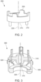
- FIG. 2 depicts a perspective view of an exemplary anti-rotation device.
- An anti-rotation device 200 includes one or more castellations 205.
- the anti-rotation device 200 includes one or more pins 210.
- the pins 210 are exemplary of distal coupling members.
- the castellations 205 and the pins 210 are fixedly coupled to a cylindrical ring 215.
- the castellations 205 protrude proximally (e.g., upward), and the pins protrude distally (e.g., downward) from the cylindrical ring 215.
- the one or more castellations 205 hold a connector (e.g., FIG. 1 , connector disk 145) from rotating with respect to an assembly body (e.g., FIG.
- the pins 210 may be locating features to facilitate user assembly of various anti-rotation devices (e.g., anti-rotation device 200) into a proper position.
- An inherent shear strength of the pins 210 and/or the castellations 205 may resist substantially high torque about a longitudinal axis 220.
- the pins 210 and the castellations 205 provide resistance to one or more degrees of freedom.
- substantially high torque may include anti-rotation device pins 210 and/or castellations 205 withstanding torques applied to anti-rotation devices 200 of up to, for example, about 1, 2, 3, 4, 5, 6, 7, 8, 9, 10, 12, 14, 16, 18, 20, 25, 30, 35, or up to about 40 Nm or more.
- FIG. 3 depicts a perspective view of an exemplary anti-rotation device anchor point in an exemplary top cover.
- a sensor subassembly 300 includes an exemplary top cover 305.
- a connector disk 310 is proximate to, and concentrically seated on top of the top cover 305.
- an anti-rotation device e.g., FIG. 2 , anti-rotation device 200
- the top cover 305 includes an anchoring aperture 315.
- the anchoring aperture 315 may mate with a pin (e.g., FIG. 2 , pin 210) of the anti-rotation device.
- the connector disk 310 may include one or more slots 320 on a bottom side.
- the one or more slots may mate with a castellation (e.g., FIG. 2 castellation 205).
- An anti-rotation device located between the top cover 305 and the connector disk 310 holds the top cover 305 and the connector disk 310 in a fixed rotational relationship about a longitudinal axis 325.
- FIG. 4A depicts a perspective bottom view of an exemplary anti-rotation device.
- An anti-rotation device 400 is fixedly coupled to two anti-rotation pins 405.
- the anti-rotation pins are exemplary of distal coupling members.
- the anti-rotation device 400 may include one or more anti-rotation pins 405.
- FIG. 4B depicts a perspective top view of the exemplary anti-rotation device 400.
- the anti-rotation device 400 is fixedly coupled to four anti-rotation tabs 410.
- the anti-rotation device 400 may include one or more anti-rotation tabs 410.
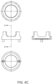
- FIG. 4C depicts a mechanical drawing of an exemplary anti-rotation device having exemplary dimensions.
- FIG. 5 depicts a perspective view of an exemplary anti-rotation device which is not in accordance with the claimed invention.
- an anti-rotation device 500 includes a ring 505.
- the ring 505 includes one or more slots 510.
- the slots 510 are disposed around the lower circumference of the ring 505, each slot 510 having an axis radial to the axis of the ring 505.
- the ring 505 includes one or more protruding tabs 515.
- the tabs 515 are unitary with the ring 505 and protrude upward from an upper circumference of the ring 505.
- FIG. 6 depicts a perspective view of an exemplary anti-rotation device which is not in accordance with the claimed invention.
- an anti-rotation device 600 includes a ring 605.
- the ring 605 is fixedly coupled to one or more top side pins 610 and one or more bottom side pins 615.
- FIG. 7 depicts a perspective view of an exemplary anti-rotation device which is not in accordance with the claimed invention.
- an anti-rotation device 700 includes a unitary ring 705.
- the unitary ring 705 includes one or more top castellated slots 710 and bottom castellated slots 715.
- FIG. 8 depicts a perspective view of an exemplary anti-rotation device which is not in accordance with the claimed invention.
- an anti-rotation device 800 includes a detent 805 and a slot 810.
- the anti-rotation device 800 may include one or more detents 805 and/or slots 810.
- the slots 810 and detents 805 may aid in manufacture of the anti-rotation device 800.
- various slots 810 and/or detents 805 may provide a snap-in-place feature, holding the anti-rotation device 800 in place while the rest of the assembly comes together.
- various anti-rotation devices may be press-fit into a top cover (e.g., FIG. 1 , top cover 120).
- an anti-rotation apparatus may fit within a cylindrical sensor assembly.
- the cylindrical sensor assembly may include a cylindrical housing.
- the cylindrical housing may be proximate to a connector disk.
- the anti-rotation apparatus substantially restricts a relative motion between a connector disk and a cylindrical housing.
- substantially restrict may be characterized by relative motion, for example, of about 0° or less than about 1°, 2°, 3°, 4°, 5°, 6°, 7°, 8°, 9° or about 10°.
- the anti-rotation apparatus includes a substantially shallow and hollow cylindrical housing having a first longitudinal axis.
- the substantially shallow cylindrical housing is a cylindrical ring.
- the anti-rotation apparatus includes one or more protrusions extending downward from the bottom of the cylindrical ring.
- the protrusions include a second longitudinal axis substantially parallel to the first longitudinal axis.
- the anti-rotation apparatus may include one or more extrusions extending upward from the top of the cylindrical ring.
- the extrusions may include a third longitudinal axis substantially parallel to the first longitudinal axis.
- substantially parallel angle deltas may be, for example, about 0° or about 1°, 2°, 3°, 4°, 5°, 6°, 7°, 8°, 9° or up to about 10° or more.
- substantially shallow cylindrical housings may be characterized as having a depth of about 2.54mm, 5.08mm, 7.62mm, 10.16mm, 12.7mm, 15.24mm, 17.78mm, 20.32mm, 22.86mm or up to about 25.4mm or more.
- the protrusions may be press-fit into the ring.
- the protrusions may be a cylindrical metal pin, which may be press-fit into the ring.
- the ring may include various synthetic materials and/or polymers (e.g., plastics, nylon, urethane). In some examples, the ring may include rubber.
- the cylindrical ring, the protrusions and the extrusions may be integrally formed in a mold.
- various integrally formed anti-rotation devices may be injection molded.
- Various exemplary anti-rotation devices may be manufactured with two-plate molds.
- the anti-rotation device may be stamped sheet steel.
- various anti-rotation devices may be stamped or die-cut sheet plastic.
- Some embodiments may include various polymers.
- nylon may be included in various anti-rotation devices and may provide strong rotational resistance cost-effectively. Nylon may provide resistance to substantially high torque.
- substantially high torque may include anti-rotation device withstanding torques, for example, of up to about 1, 2, 3, 4, 5, 6, 7, 8, 9, 10, 12, 14, 16, 18, 20, 25, 30, 35, or up to about 40 Nm or more.
- the anti-rotation devices may include thermoplastic rubber (TPR), which may advantageously provides flexibility and energy absorption from various impacts.
- various anti-rotation devices may include styrene-ethylenebutylene-styrene (SEBS), which advantageously provides weather resistance and heat resistance.
- SEBS styrene-ethylenebutylene-styrene
- various anti-rotation devices may include thermoplastic polyurethane (TPU), which advantageously provides exceptional performance in cold temperatures, and resistance to water and various petroleum products.
- various anti-rotation devices may include polyvinyl chloride (PVC), which advantageously mixes well with other substances, and provides impact resistance.
- Various examples of anti-rotation devices may include silicon rubber, which advantageously provides heat resistance, resistance to cold temperatures and electrical insulation.
- various anti-rotation devices may include thermoset, which advantageously provides high strength and durability.
- various anti-rotation devices may include various forms of metal or metal alloys, which may provide exceptional strength.
- some anti-rotation devices may include carbon fiber, which advantageously is lightweight and provides high strength and rigidity.
- Various anti-rotation devices may include fiberglass, which is cost-effective, lightweight and rigid.
- Various anti-rotation devices may include ceramic, which is heat resistant, lightweight and rigid.
- the anti-rotation devices may include one or more colors.
- the color(s) may be indicative of the manufacturer or company colors.
- various colors may be combined to depict various images or lettering.
- various anti-rotation devices may be transparent which may, for example, aid inspection and increase quality.
- various anti-rotation devices may include polyamide. Polyamide advantageously withstands substantially high torque.
- the anti-rotation device may include one or more metals.
- various embodiments may include aluminum, which advantageously provides light weight and high strength.
- anti-rotation device may include steel, which provides high strength cost-effectively.
- Various examples of protrusions, tabs, castellations and/or pins may be rectangular prisms, which provide straight-forward mold design.
- Various examples of protrusions, tabs, castellations and/or pins may be frustoconical, which facilitate mold release.
- Various examples of protrusions, tabs, castellations and/or pins may be cylindrical, which optimize strength.
- various anti-rotation devices may be unitary with the connector disk. Further, in some examples, various anti-rotation devices may be unitary with the top cover. By way of example, various anti-rotation devices such as, for example, some or all of the anti-rotation devices 125, 200, 400, 500, 600, 700, 800 are configured for maintaining the top cover 120 and the connector disk 145 in a fixed rotational relationship.
Landscapes
- Engineering & Computer Science (AREA)
- Microelectronics & Electronic Packaging (AREA)
- Measuring Fluid Pressure (AREA)
- Injection Moulding Of Plastics Or The Like (AREA)
- Transmission And Conversion Of Sensor Element Output (AREA)
- Details Of Connecting Devices For Male And Female Coupling (AREA)
Description
- Various embodiments relate generally to mechanical accessories to electrically detachable circular connectors. In particular, embodiments relate to a sensor assembly for wired assemblies having circular connection.
- Gage and absolute sensors may be deployed in some of the world's most rugged environments. For example, various deployment environments may include operations pertaining to the include oil and gas industry. Electrical connectors used in these deployments may be designed, manufactured and tested to meet demanding specifications. Some sensor manufacturers may develop and refine their designs to meet specific end-user applications. In various examples, industry-standard DIN 43650 circular connectors may employ a fast-lock technology to avoid screwing operations, which may be viewed as cumbersome in field installation situations.
EP2797176A1 discloses a sensor unit with a sensor, sensor electronics connected to the sensor and a first connection unit which is connected to the sensor electronics, the sensor, the sensor electronics and the first connection unit are arranged in a tubular housing and the first connection unit can be contacted with a correspondingly designed second connection unit, a molded part with an inner contour in the housing. is arranged in a rotationally fixed manner, the inner contour and an outer contour of the first connecting unit and / or the second connecting unit being at least partially designed to correspond to one another.WO02/052239A1
EP3133701A1 discloses an active input/output connector which includes a first printed circuit board and a second printed circuit board enclosed within a housing. A first plug is in electronic communication with the first printed circuit board. A second plug is in electronic communication with the second printed circuit board. The first and second printed circuit boards are connected for communication of sensor signals from the first plug to the second plug.
US2001/002348A1 discloses a backshell of an electrical connector which has an outer nut screwed onto the rear of the connector front assembly, which is formed with triangular locking teeth. An internal assembly within the nut prevents rotation of the backshell on the connector when locked in position. The internal assembly includes a rear cylinder and a forward annular member located between the cylinder and the front assembly. The cylinder is of metal-plated plastics, which makes electrical connection at its rear end with screens of cables within the connector. The annular member is of a metal and at its forward end has triangular teeth that engage the teeth at the rear of the front assembly. The rear of the annular member and the forward end of the cylinder both have rounded teeth and that engage with one another so as to avoid sharp edges on the cylinder that could lead to damage to its plating caused by electrical transients. - A sensor assembly according to the invention is defined in independent claim 1 and comprises an anti-rotation device including a cylindrical ring extending along a longitudinal axis, the ring including proximal and distal faces. In an illustrative example, the ring includes proximal coupling members extending from the proximal face insertably engaging with mating recesses within a connector-disk. The ring may includes distal coupling members extending from the distal face insertably engaging with mating recesses within a body-assembly, for example. The coupling members extend parallel to the longitudinal axis. The anti-rotation device is captured between the connector-disk and the body-assembly and is retained by a proximal twist-lock cap screwably engaged with the body-assembly, such that relative rotational motion between the connector-disk and the body-assembly is substantially restricted. Various anti-rotation devices substantially restrict relative rotational motion between connector-disks and body-assemblies advantageously mitigating disconnection of wiring harnesses in circular connector applications.
- Various embodiments achieve one or more advantages. For example, some implementations may extend the life of various sensors and other electronic equipment, reducing costly down-time, field diagnosis and repair operations. Various implementations may improve dependability in DIN-mounted (Deutsches Institut für Normung) electrical equipment, by avoiding twist-stress which may induce marginal wiring harness connections that pass manufacturing tests but may cause latent failures in the field. Various anti-rotation devices may be injection molded with thermoplastic withstanding up to 125°C or more. Some examples may be cost-effectively implemented in various Honeywell electronic sensors. Various embodiments may be deployed in harsh environments, such as oil and gas applications. Some embodiments may be intuitively implemented with various connector disks and top covers. Some embodiments may include various metals and may provide a robust quality measure.
- The details of various embodiments are set forth in the accompanying drawings and the description below. Other features and advantages will be apparent from the description and drawings, and from the claims. The invention is set out in the appended claims.
-
-
FIG. 1 depicts an exploded perspective view of an exemplary anti-rotation device incorporated within a sensor assembly stack-up including a DIN connector disk. -
FIG. 2 depicts a perspective view of an exemplary anti-rotation device. -
FIG. 3 depicts a perspective view of an exemplary anti-rotation device anchor point in an exemplary top cover. -
FIG. 4A depicts a perspective bottom view of an exemplary anti-rotation device. -
FIG. 4B depicts a perspective top view of an exemplary anti-rotation device. -
FIG. 4C depicts a mechanical drawing of an exemplary anti-rotation device. -
FIGs. 5, 6, 7 and8 depict perspective views of exemplary anti-rotation devices which are not in accordance with the claimed invention. - Like reference symbols in the various drawings indicate like elements.
- To aid understanding, this document is organized as follows. First, an illustrative implementation of an exemplary anti-rotation device is briefly introduced with reference to
FIG. 1 . Second, with reference toFIG. 2 an exemplary anti-rotation device is described in more detail. InFIG. 3 , the discussion turns to exemplary features in proximate components. Finally, with reference toFIG. 4-8 , various anti-rotation embodiments are presented. Throughout this document, "connector disk" may be an electrical connector that is detachable. -
FIG. 1 depicts an exploded perspective view of an exemplary anti-rotation device incorporated within a sensor assembly stack-up including a DIN connector disk. Asensor assembly 100 includes asensor body 105. Thesensor body 105 is fixedly coupled to asensing module 110. Thesensing module 110 is fixedly coupled to one ormore module terminals 115. Thesensor body 105 is fixedly coupled to atop cover 120. Ananti-rotation device 125 fits inside thetop cover 120. - The
anti-rotation device 125 includes one or more unitarily formedextrusions 130. Theextrusions 130 are exemplary of distal coupling members. The one ormore extrusions 130 are configured to fit within one or more apertures (not shown) located within thetop cover 120. Theextrusions 130 inserted into the apertures mitigate relative rotation between thetop cover 120 and theanti-rotation device 125 about alongitudinal axis 135. - The
anti-rotation device 125 includes one or more unitarily formedcastellated protrusions 140. Thecastellated protrusions 140 are configured to fit within various recesses in aconnector disk 145. Theconnector disk 145 is fixedly coupled to one ormore connector terminals 150. Theconnector terminals 150 are operatively coupled to themodule terminals 115 via awiring harness 155. In various embodiments, theconnector disk 145 may be a DIN 43650 male connector. Thecastellated protrusions 140 inserted into the recesses mitigate relative rotation between theconnector disk 145 and theanti-rotation device 125 about thelongitudinal axis 135. - Accordingly, the
anti-rotation device 125 mitigates relative rotation between thetop cover 120 and theconnector disk 145. Since thetop cover 120, thesensor body 105, thesensing module 110 and themodule terminals 115 are all in fixed spatial relationships, and since theanti-rotation device 125 holds thetop cover 120 and theconnector disk 145 in a fixed rotational relationship, then theconnector terminals 150 and themodule terminals 115 are advantageously held in a fixed rotational relationship about thelongitudinal axis 135. This fixed rotational relationship advantageously mitigates twisting stresses of the wiring harnesses 155 about thelongitudinal axis 135. - The
top cover 120, theanti-rotation device 125 and theconnector disk 145 are captured and held within thesensor body 105 by a twist-lock cap 160. Although a bottom-facing inside surface of the twist-lock cap 160 is in contact with a top surface of theconnector disk 145 while the twist-lock cap 160 is rotated with respect to thesensor body 105, theconnector disk 145 remains in a fixed rotational relationship with thesensor body 105, thesensing module 110 and themodule terminals 115 due to the inclusion of theanti-rotation device 125. - The
anti-rotation device 125 mitigates twisting stresses during manufacture of thesensor assembly 100, reducing the occurrence of compromised connections on thewiring harness 155. Mitigation of compromised connections on thewiring harness 155 may advantageously increase the working life and overall quality ofvarious sensor assemblies 100. - The
anti-rotation device 125 mitigates twisting stresses in the field due to vibration, in various implementations. For example, an industrial machine may include a sensor assembly, such assensor assembly 100 implemented with a DIN 43650 connector. As the machine vibrates, rotation of theconnector disk 145 with respect to theinternal sensing module 110 is mitigated. Thewiring harness 155 remains intact during deployment, which may avoid latent failure and expensive down-time. - In various examples, a body-assembly may include the
sensor body 105, thesensing module 110, themodule terminals 115, thetop cover 120, and the wiring harnesses 155. The components making up the body-assembly may be fixedly coupled to one another. In some examples, thewiring harness 155 is fixedly coupled on a distal end, to themodule terminals 115. During various assembly processes, the body-assembly, via thewiring harness 155, may be fixedly coupled on a proximal end, to the connector-disk 145. -
FIG. 2 depicts a perspective view of an exemplary anti-rotation device. Ananti-rotation device 200 includes one or more castellations 205. Theanti-rotation device 200 includes one or more pins 210. Thepins 210 are exemplary of distal coupling members. Thecastellations 205 and thepins 210 are fixedly coupled to acylindrical ring 215. In the depicted example, thecastellations 205 protrude proximally (e.g., upward), and the pins protrude distally (e.g., downward) from thecylindrical ring 215. The one ormore castellations 205 hold a connector (e.g.,FIG. 1 , connector disk 145) from rotating with respect to an assembly body (e.g.,FIG. 1 , sensor body 105) during various manufacturing operations. In some examples, thepins 210 may be locating features to facilitate user assembly of various anti-rotation devices (e.g., anti-rotation device 200) into a proper position. An inherent shear strength of thepins 210 and/or thecastellations 205 may resist substantially high torque about alongitudinal axis 220. Thepins 210 and thecastellations 205 provide resistance to one or more degrees of freedom. In some implementations, "substantially high torque" may include anti-rotation device pins 210 and/orcastellations 205 withstanding torques applied toanti-rotation devices 200 of up to, for example, about 1, 2, 3, 4, 5, 6, 7, 8, 9, 10, 12, 14, 16, 18, 20, 25, 30, 35, or up to about 40 Nm or more. -
FIG. 3 depicts a perspective view of an exemplary anti-rotation device anchor point in an exemplary top cover. Asensor subassembly 300 includes an exemplarytop cover 305. Aconnector disk 310 is proximate to, and concentrically seated on top of thetop cover 305. In various examples, an anti-rotation device (e.g.,FIG. 2 , anti-rotation device 200) may be sandwiched between thetop cover 305 and theconnector disk 310. Thetop cover 305 includes an anchoringaperture 315. The anchoringaperture 315 may mate with a pin (e.g.,FIG. 2 , pin 210) of the anti-rotation device. Theconnector disk 310 may include one ormore slots 320 on a bottom side. The one or more slots may mate with a castellation (e.g.,FIG. 2 castellation 205). An anti-rotation device, located between thetop cover 305 and theconnector disk 310 holds thetop cover 305 and theconnector disk 310 in a fixed rotational relationship about alongitudinal axis 325. -
FIG. 4A depicts a perspective bottom view of an exemplary anti-rotation device. Ananti-rotation device 400 is fixedly coupled to twoanti-rotation pins 405. The anti-rotation pins are exemplary of distal coupling members. In various examples, theanti-rotation device 400 may include one or more anti-rotation pins 405.FIG. 4B depicts a perspective top view of theexemplary anti-rotation device 400. Theanti-rotation device 400 is fixedly coupled to fouranti-rotation tabs 410. In various examples, theanti-rotation device 400 may include one or moreanti-rotation tabs 410.FIG. 4C depicts a mechanical drawing of an exemplary anti-rotation device having exemplary dimensions. -
FIG. 5 depicts a perspective view of an exemplary anti-rotation device which is not in accordance with the claimed invention. In the depicted example, ananti-rotation device 500 includes aring 505. Thering 505 includes one ormore slots 510. In the depicted example, theslots 510 are disposed around the lower circumference of thering 505, eachslot 510 having an axis radial to the axis of thering 505. Thering 505 includes one or moreprotruding tabs 515. In the depicted example, thetabs 515 are unitary with thering 505 and protrude upward from an upper circumference of thering 505. -
FIG. 6 depicts a perspective view of an exemplary anti-rotation device which is not in accordance with the claimed invention. In the depicted example, ananti-rotation device 600 includes aring 605. Thering 605 is fixedly coupled to one or more top side pins 610 and one or more bottom side pins 615. -
FIG. 7 depicts a perspective view of an exemplary anti-rotation device which is not in accordance with the claimed invention. In the depicted example, ananti-rotation device 700 includes aunitary ring 705. Theunitary ring 705 includes one or more topcastellated slots 710 and bottomcastellated slots 715. -
FIG. 8 depicts a perspective view of an exemplary anti-rotation device which is not in accordance with the claimed invention. In the depicted example, ananti-rotation device 800 includes adetent 805 and aslot 810. Theanti-rotation device 800 may include one ormore detents 805 and/orslots 810. Theslots 810 anddetents 805 may aid in manufacture of theanti-rotation device 800. For example,various slots 810 and/ordetents 805 may provide a snap-in-place feature, holding theanti-rotation device 800 in place while the rest of the assembly comes together. - Although various embodiments have been described with reference to the figures, other embodiments are possible. For example, various anti-rotation devices may be press-fit into a top cover (e.g.,
FIG. 1 , top cover 120). - In an exemplary aspect, an anti-rotation apparatus may fit within a cylindrical sensor assembly. The cylindrical sensor assembly may include a cylindrical housing. The cylindrical housing may be proximate to a connector disk. The anti-rotation apparatus substantially restricts a relative motion between a connector disk and a cylindrical housing. In various implementations, "substantially restrict" may be characterized by relative motion, for example, of about 0° or less than about 1°, 2°, 3°, 4°, 5°, 6°, 7°, 8°, 9° or about 10°.
- The anti-rotation apparatus includes a substantially shallow and hollow cylindrical housing having a first longitudinal axis. The substantially shallow cylindrical housing is a cylindrical ring. The anti-rotation apparatus includes one or more protrusions extending downward from the bottom of the cylindrical ring. In some examples, the protrusions include a second longitudinal axis substantially parallel to the first longitudinal axis. The anti-rotation apparatus may include one or more extrusions extending upward from the top of the cylindrical ring. In some examples, the extrusions may include a third longitudinal axis substantially parallel to the first longitudinal axis. In various examples, "substantially parallel" angle deltas may be, for example, about 0° or about 1°, 2°, 3°, 4°, 5°, 6°, 7°, 8°, 9° or up to about 10° or more. In various examples, "substantially shallow" cylindrical housings may be characterized as having a depth of about 2.54mm, 5.08mm, 7.62mm, 10.16mm, 12.7mm, 15.24mm, 17.78mm, 20.32mm, 22.86mm or up to about 25.4mm or more.
- In various implementations, the protrusions may be press-fit into the ring. For example, the protrusions may be a cylindrical metal pin, which may be press-fit into the ring. The ring may include various synthetic materials and/or polymers (e.g., plastics, nylon, urethane). In some examples, the ring may include rubber.
- In various implementations, the cylindrical ring, the protrusions and the extrusions may be integrally formed in a mold. For example, various integrally formed anti-rotation devices may be injection molded. Various exemplary anti-rotation devices may be manufactured with two-plate molds. In various examples, the anti-rotation device may be stamped sheet steel. Further, various anti-rotation devices may be stamped or die-cut sheet plastic.
- Some embodiments may include various polymers. For example, nylon may be included in various anti-rotation devices and may provide strong rotational resistance cost-effectively. Nylon may provide resistance to substantially high torque. In some implementations, "substantially high torque" may include anti-rotation device withstanding torques, for example, of up to about 1, 2, 3, 4, 5, 6, 7, 8, 9, 10, 12, 14, 16, 18, 20, 25, 30, 35, or up to about 40 Nm or more.
- In some examples, the anti-rotation devices may include thermoplastic rubber (TPR), which may advantageously provides flexibility and energy absorption from various impacts. In some embodiments, various anti-rotation devices may include styrene-ethylenebutylene-styrene (SEBS), which advantageously provides weather resistance and heat resistance. In various examples, various anti-rotation devices may include thermoplastic polyurethane (TPU), which advantageously provides exceptional performance in cold temperatures, and resistance to water and various petroleum products. In some examples, various anti-rotation devices may include polyvinyl chloride (PVC), which advantageously mixes well with other substances, and provides impact resistance. Various examples of anti-rotation devices may include silicon rubber, which advantageously provides heat resistance, resistance to cold temperatures and electrical insulation. In some embodiments, various anti-rotation devices may include thermoset, which advantageously provides high strength and durability. In various implementations, various anti-rotation devices may include various forms of metal or metal alloys, which may provide exceptional strength. In various implementations, some anti-rotation devices may include carbon fiber, which advantageously is lightweight and provides high strength and rigidity. Various anti-rotation devices may include fiberglass, which is cost-effective, lightweight and rigid. Various anti-rotation devices may include ceramic, which is heat resistant, lightweight and rigid.
- In various examples, the anti-rotation devices may include one or more colors. The color(s) may be indicative of the manufacturer or company colors. In some implementations, various colors may be combined to depict various images or lettering. Further, various anti-rotation devices may be transparent which may, for example, aid inspection and increase quality. In some implementations, various anti-rotation devices may include polyamide. Polyamide advantageously withstands substantially high torque.
- In various examples, the anti-rotation device may include one or more metals. For example, various embodiments may include aluminum, which advantageously provides light weight and high strength. In some examples, anti-rotation device may include steel, which provides high strength cost-effectively. Various examples of protrusions, tabs, castellations and/or pins may be rectangular prisms, which provide straight-forward mold design. Various examples of protrusions, tabs, castellations and/or pins may be frustoconical, which facilitate mold release. Various examples of protrusions, tabs, castellations and/or pins may be cylindrical, which optimize strength.
- In some examples, various anti-rotation devices may be unitary with the connector disk. Further, in some examples, various anti-rotation devices may be unitary with the top cover. By way of example, various anti-rotation devices such as, for example, some or all of the
anti-rotation devices top cover 120 and theconnector disk 145 in a fixed rotational relationship.
Claims (10)
- A sensor assembly (100) for wired assemblies having a circular connection, the apparatus comprising:a sensor body (105) defining a first tubular interior chamber that extends between a proximal end and a distal end along a longitudinal axis (135, 220, 325);a top cover (120) disposed in the first tubular interior chamber and defining at least one anchoring aperture (315), the top cover (120) being fixedly coupled to the sensor body (105);a connector disk (145, 310) comprising a detachable electrical connector and at least one recess;a twist-lock cap (160) configured to threadedly engage the sensor body (105) to securably capture the connector disk (145, 310) proximally and concentrically registered with a proximal end of the sensor body (105);a wiring harness (155) extending through the first tubular interior chamber, wherein a distal end of the wiring harness fixedly attaches proximate to the distal end of the sensor body (105); and,an anti-rotation device (125, 200, 400) comprising a ring (215) configured in a cylindrical shape and to extend along the longitudinal axis between a proximal face and a distal face, the ring (215) comprising:at least one distal coupling member (130, 210, 405) extending from the distal face and configured to insertably engage with a corresponding one of the at least one anchoring apertures (315); andat least one castellation (140, 205, 410) extending from the proximal face of the ring (215) and configured to insertably engage with a corresponding one of the at least one recess (320) of the connector disk (145, 310), so as to mitigate relative rotation between the connector disk (145, 310) and the anti-rotation device (125) about the longitudinal axis (135, 220, 325),wherein, when the twist-lock cap (160) screwably engages the sensor body (105) during assembly, the anti-rotation device (125, 200, 400) is captured between the connector-disk (145, 310) and the sensor body (105) and retained in a fixed orientation within the first tubular interior chamber such that the anti-rotation device (125, 200, 400) substantially restricts relative rotation between the connector disk (145, 310) and the sensor body (105).
- The sensor assembly (100) of claim 1, wherein the top cover (120) is defining a second tubular interior chamber that extends along the longitudinal axis (135, 220, 325) and is configured to coaxially align with the first tubular interior chamber proximate to the distal end.
- The sensor assembly (100) of claim 1, wherein the sensor body (105) further comprises threads for longitudinal engagement of the twist-lock cap (160) to the proximal end of the sensor body (105).
- The sensor assembly (100) of claim 1, wherein the connector disk (310) further comprises a plurality of terminals that are electrically and mechanically connected to a proximal end of the wiring harness (155).
- The sensor assembly (100) of claim 1, further comprising a sensing module (110) disposed proximate to the distal end of the first tubular interior chamber, the sensing module comprising at least one module terminal (115), wherein the sensing module is fixedly coupled to the sensor body (105), and the distal end of the wiring harness (155) fixedly attaches to the at least one module terminal (115).
- The sensor assembly (100) of claim 1, wherein the anti-rotation device (125, 200, 400) is formed by an injection molding process.
- The sensor assembly (100) of claim 6, wherein the anti-rotation device (125, 200, 400) is further formed of a thermoplastic.
- The sensor assembly (100) of claim 7, wherein the thermoplastic is rated to withstand temperature up to 125 degrees Celsius.
- The sensor assembly (100) of claim 1, wherein the anti-rotation device (125, 200, 400) is formed of a visually transparent material.
- The sensor assembly (100) of claim 1, wherein the at least one distal coupling member (130, 210, 405) is press-fit into the distal face of the ring (215).
Applications Claiming Priority (1)
| Application Number | Priority Date | Filing Date | Title |
|---|---|---|---|
| IN201811009512 | 2018-03-15 |
Publications (2)
| Publication Number | Publication Date |
|---|---|
| EP3540870A1 EP3540870A1 (en) | 2019-09-18 |
| EP3540870B1 true EP3540870B1 (en) | 2025-01-15 |
Family
ID=65812112
Family Applications (1)
| Application Number | Title | Priority Date | Filing Date |
|---|---|---|---|
| EP19162680.3A Active EP3540870B1 (en) | 2018-03-15 | 2019-03-13 | Anti-rotation device for circular connector |
Country Status (3)
| Country | Link |
|---|---|
| US (1) | US10553988B2 (en) |
| EP (1) | EP3540870B1 (en) |
| CN (1) | CN110277690B (en) |
Families Citing this family (1)
| Publication number | Priority date | Publication date | Assignee | Title |
|---|---|---|---|---|
| CN117117547A (en) * | 2023-10-12 | 2023-11-24 | 鸿宝时(三河)科技有限公司 | A universal electrical connector installation and fixation combination adapter |
Family Cites Families (7)
| Publication number | Priority date | Publication date | Assignee | Title |
|---|---|---|---|---|
| US4693538A (en) * | 1986-05-02 | 1987-09-15 | Shiba Seisakusho Limited Responsibility Company | Insulator for electric terminal attached to electric wire |
| GB9928256D0 (en) | 1999-11-30 | 2000-01-26 | Smiths Industries Plc | Electrical couplings,connectors and components |
| DE10064811A1 (en) | 2000-12-22 | 2002-06-27 | Endress & Hauser Gmbh & Co Kg | Pressure measurement device with improved mounting mechanism that prevents transfer of torque caused by a sealing screw element on to the pressure sensor itself with a corresponding loss of measurement accuracy |
| US6902414B2 (en) * | 2003-09-29 | 2005-06-07 | Extreme Engineering Ltd. | Harsh environment rotatable connector |
| EP2797176B1 (en) | 2013-04-26 | 2016-06-29 | VEGA Grieshaber KG | Sensor unit |
| US10198391B2 (en) | 2015-08-20 | 2019-02-05 | Hamilton Sunstrand Corporation | Integrated input/output connector |
| CN207074770U (en) * | 2017-06-01 | 2018-03-06 | 西门子公司 | Usb expansion interface, USB interface component, electric control cabinet |
-
2019
- 2019-03-12 US US16/299,901 patent/US10553988B2/en active Active
- 2019-03-13 EP EP19162680.3A patent/EP3540870B1/en active Active
- 2019-03-15 CN CN201910201966.4A patent/CN110277690B/en active Active
Also Published As
| Publication number | Publication date |
|---|---|
| EP3540870A1 (en) | 2019-09-18 |
| US20190288442A1 (en) | 2019-09-19 |
| CN110277690B (en) | 2021-03-09 |
| US10553988B2 (en) | 2020-02-04 |
| CN110277690A (en) | 2019-09-24 |
Similar Documents
| Publication | Publication Date | Title |
|---|---|---|
| US8956166B2 (en) | Apparatus for electrically connecting a flexible circuit to a receiver | |
| KR101467728B1 (en) | Header connector assembly | |
| CN102821983B (en) | Devices for monitoring wheels | |
| US10250784B2 (en) | Camera assembly with shielded imager circuit | |
| US10074924B2 (en) | Receptacle connector and camera unit | |
| CN101378162B (en) | Connector, jack socket component, electronic equipment and plug component | |
| CA2821694C (en) | Wireless measurement transmitter with replaceable module | |
| US8821167B2 (en) | Apparatus for electrically connecting a flexible circuit to a receiver | |
| US20130337693A1 (en) | Connector | |
| JP5187648B2 (en) | connector | |
| US20160223417A1 (en) | Low profile pressure sensor | |
| CN111238720B (en) | Sensor assembly and physical quantity measuring device | |
| EP3202239B1 (en) | Transmitter for a field device using a seal board assembly | |
| US10553988B2 (en) | Anti-rotation device for circular connector | |
| CN111751046B (en) | Physical quantity measuring device and method for manufacturing physical quantity measuring device | |
| CN114069339A (en) | Front plate for a housing of a control device, housing module, connector assembly and vehicle | |
| US12095192B2 (en) | Compressible conductive elastomer for electrical connection of orthogonal substrates | |
| US12155145B2 (en) | Method for producing an electrical connector, in particular an electrical connector for a high-density header system; as well as an electrical connector, in particular an electrical connector for the motor vehicle industry; as well as high-density header system | |
| KR102408569B1 (en) | Pressure sensor unit | |
| CA2924338C (en) | Apparatus and method for connecting a cable to a high temperature circuit | |
| KR102959992B1 (en) | Physical quantity measuring device | |
| CN222850092U (en) | Temperature pressure sensor's casing, temperature pressure sensor and vehicle | |
| CN213932943U (en) | Sensor unit | |
| KR20200144749A (en) | Overmolding electronic control unit having test pin module | |
| CN213422509U (en) | Sensor unit |
Legal Events
| Date | Code | Title | Description |
|---|---|---|---|
| PUAI | Public reference made under article 153(3) epc to a published international application that has entered the european phase |
Free format text: ORIGINAL CODE: 0009012 |
|
| STAA | Information on the status of an ep patent application or granted ep patent |
Free format text: STATUS: REQUEST FOR EXAMINATION WAS MADE |
|
| 17P | Request for examination filed |
Effective date: 20190313 |
|
| AK | Designated contracting states |
Kind code of ref document: A1 Designated state(s): AL AT BE BG CH CY CZ DE DK EE ES FI FR GB GR HR HU IE IS IT LI LT LU LV MC MK MT NL NO PL PT RO RS SE SI SK SM TR |
|
| AX | Request for extension of the european patent |
Extension state: BA ME |
|
| STAA | Information on the status of an ep patent application or granted ep patent |
Free format text: STATUS: EXAMINATION IS IN PROGRESS |
|
| 17Q | First examination report despatched |
Effective date: 20210331 |
|
| GRAP | Despatch of communication of intention to grant a patent |
Free format text: ORIGINAL CODE: EPIDOSNIGR1 |
|
| STAA | Information on the status of an ep patent application or granted ep patent |
Free format text: STATUS: GRANT OF PATENT IS INTENDED |
|
| INTG | Intention to grant announced |
Effective date: 20240808 |
|
| GRAS | Grant fee paid |
Free format text: ORIGINAL CODE: EPIDOSNIGR3 |
|
| GRAA | (expected) grant |
Free format text: ORIGINAL CODE: 0009210 |
|
| STAA | Information on the status of an ep patent application or granted ep patent |
Free format text: STATUS: THE PATENT HAS BEEN GRANTED |
|
| REG | Reference to a national code |
Ref country code: DE Ref legal event code: R081 Ref document number: 602019064795 Country of ref document: DE Owner name: HONEYWELL INTERNATIONAL INC., MORRIS PLAINS, US Free format text: FORMER OWNER: HONEYWELL INTERNATIONAL INC. INTELLECTUAL PROPERTY - PATENT SERVICES, MORRIS PLAINS, NJ, US |
|
| AK | Designated contracting states |
Kind code of ref document: B1 Designated state(s): AL AT BE BG CH CY CZ DE DK EE ES FI FR GB GR HR HU IE IS IT LI LT LU LV MC MK MT NL NO PL PT RO RS SE SI SK SM TR |
|
| REG | Reference to a national code |
Ref country code: CH Ref legal event code: EP Ref country code: GB Ref legal event code: FG4D |
|
| REG | Reference to a national code |
Ref country code: DE Ref legal event code: R096 Ref document number: 602019064795 Country of ref document: DE |
|
| REG | Reference to a national code |
Ref country code: IE Ref legal event code: FG4D |
|
| REG | Reference to a national code |
Ref country code: NL Ref legal event code: MP Effective date: 20250115 |
|
| PG25 | Lapsed in a contracting state [announced via postgrant information from national office to epo] |
Ref country code: NL Free format text: LAPSE BECAUSE OF FAILURE TO SUBMIT A TRANSLATION OF THE DESCRIPTION OR TO PAY THE FEE WITHIN THE PRESCRIBED TIME-LIMIT Effective date: 20250115 |
|
| PG25 | Lapsed in a contracting state [announced via postgrant information from national office to epo] |
Ref country code: RS Free format text: LAPSE BECAUSE OF FAILURE TO SUBMIT A TRANSLATION OF THE DESCRIPTION OR TO PAY THE FEE WITHIN THE PRESCRIBED TIME-LIMIT Effective date: 20250415 |
|
| PG25 | Lapsed in a contracting state [announced via postgrant information from national office to epo] |
Ref country code: FI Free format text: LAPSE BECAUSE OF FAILURE TO SUBMIT A TRANSLATION OF THE DESCRIPTION OR TO PAY THE FEE WITHIN THE PRESCRIBED TIME-LIMIT Effective date: 20250115 |
|
| PG25 | Lapsed in a contracting state [announced via postgrant information from national office to epo] |
Ref country code: PL Free format text: LAPSE BECAUSE OF FAILURE TO SUBMIT A TRANSLATION OF THE DESCRIPTION OR TO PAY THE FEE WITHIN THE PRESCRIBED TIME-LIMIT Effective date: 20250115 |
|
| PG25 | Lapsed in a contracting state [announced via postgrant information from national office to epo] |
Ref country code: ES Free format text: LAPSE BECAUSE OF FAILURE TO SUBMIT A TRANSLATION OF THE DESCRIPTION OR TO PAY THE FEE WITHIN THE PRESCRIBED TIME-LIMIT Effective date: 20250115 |
|
| REG | Reference to a national code |
Ref country code: LT Ref legal event code: MG9D |
|
| PG25 | Lapsed in a contracting state [announced via postgrant information from national office to epo] |
Ref country code: IS Free format text: LAPSE BECAUSE OF FAILURE TO SUBMIT A TRANSLATION OF THE DESCRIPTION OR TO PAY THE FEE WITHIN THE PRESCRIBED TIME-LIMIT Effective date: 20250515 Ref country code: NO Free format text: LAPSE BECAUSE OF FAILURE TO SUBMIT A TRANSLATION OF THE DESCRIPTION OR TO PAY THE FEE WITHIN THE PRESCRIBED TIME-LIMIT Effective date: 20250415 |
|
| REG | Reference to a national code |
Ref country code: AT Ref legal event code: MK05 Ref document number: 1760457 Country of ref document: AT Kind code of ref document: T Effective date: 20250115 |
|
| PG25 | Lapsed in a contracting state [announced via postgrant information from national office to epo] |
Ref country code: HR Free format text: LAPSE BECAUSE OF FAILURE TO SUBMIT A TRANSLATION OF THE DESCRIPTION OR TO PAY THE FEE WITHIN THE PRESCRIBED TIME-LIMIT Effective date: 20250115 |
|
| PG25 | Lapsed in a contracting state [announced via postgrant information from national office to epo] |
Ref country code: LV Free format text: LAPSE BECAUSE OF FAILURE TO SUBMIT A TRANSLATION OF THE DESCRIPTION OR TO PAY THE FEE WITHIN THE PRESCRIBED TIME-LIMIT Effective date: 20250115 Ref country code: PT Free format text: LAPSE BECAUSE OF FAILURE TO SUBMIT A TRANSLATION OF THE DESCRIPTION OR TO PAY THE FEE WITHIN THE PRESCRIBED TIME-LIMIT Effective date: 20250515 |
|
| PG25 | Lapsed in a contracting state [announced via postgrant information from national office to epo] |
Ref country code: BG Free format text: LAPSE BECAUSE OF FAILURE TO SUBMIT A TRANSLATION OF THE DESCRIPTION OR TO PAY THE FEE WITHIN THE PRESCRIBED TIME-LIMIT Effective date: 20250115 Ref country code: GR Free format text: LAPSE BECAUSE OF FAILURE TO SUBMIT A TRANSLATION OF THE DESCRIPTION OR TO PAY THE FEE WITHIN THE PRESCRIBED TIME-LIMIT Effective date: 20250416 |
|
| PG25 | Lapsed in a contracting state [announced via postgrant information from national office to epo] |
Ref country code: AT Free format text: LAPSE BECAUSE OF FAILURE TO SUBMIT A TRANSLATION OF THE DESCRIPTION OR TO PAY THE FEE WITHIN THE PRESCRIBED TIME-LIMIT Effective date: 20250115 |
|
| PG25 | Lapsed in a contracting state [announced via postgrant information from national office to epo] |
Ref country code: SE Free format text: LAPSE BECAUSE OF FAILURE TO SUBMIT A TRANSLATION OF THE DESCRIPTION OR TO PAY THE FEE WITHIN THE PRESCRIBED TIME-LIMIT Effective date: 20250115 |
|
| PG25 | Lapsed in a contracting state [announced via postgrant information from national office to epo] |
Ref country code: SM Free format text: LAPSE BECAUSE OF FAILURE TO SUBMIT A TRANSLATION OF THE DESCRIPTION OR TO PAY THE FEE WITHIN THE PRESCRIBED TIME-LIMIT Effective date: 20250115 |
|
| PG25 | Lapsed in a contracting state [announced via postgrant information from national office to epo] |
Ref country code: DK Free format text: LAPSE BECAUSE OF FAILURE TO SUBMIT A TRANSLATION OF THE DESCRIPTION OR TO PAY THE FEE WITHIN THE PRESCRIBED TIME-LIMIT Effective date: 20250115 |
|
| PG25 | Lapsed in a contracting state [announced via postgrant information from national office to epo] |
Ref country code: MC Free format text: LAPSE BECAUSE OF FAILURE TO SUBMIT A TRANSLATION OF THE DESCRIPTION OR TO PAY THE FEE WITHIN THE PRESCRIBED TIME-LIMIT Effective date: 20250115 |
|
| PG25 | Lapsed in a contracting state [announced via postgrant information from national office to epo] |
Ref country code: IT Free format text: LAPSE BECAUSE OF FAILURE TO SUBMIT A TRANSLATION OF THE DESCRIPTION OR TO PAY THE FEE WITHIN THE PRESCRIBED TIME-LIMIT Effective date: 20250115 |
|
| REG | Reference to a national code |
Ref country code: DE Ref legal event code: R097 Ref document number: 602019064795 Country of ref document: DE |
|
| PG25 | Lapsed in a contracting state [announced via postgrant information from national office to epo] |
Ref country code: CZ Free format text: LAPSE BECAUSE OF FAILURE TO SUBMIT A TRANSLATION OF THE DESCRIPTION OR TO PAY THE FEE WITHIN THE PRESCRIBED TIME-LIMIT Effective date: 20250115 Ref country code: EE Free format text: LAPSE BECAUSE OF FAILURE TO SUBMIT A TRANSLATION OF THE DESCRIPTION OR TO PAY THE FEE WITHIN THE PRESCRIBED TIME-LIMIT Effective date: 20250115 |
|
| PG25 | Lapsed in a contracting state [announced via postgrant information from national office to epo] |
Ref country code: RO Free format text: LAPSE BECAUSE OF FAILURE TO SUBMIT A TRANSLATION OF THE DESCRIPTION OR TO PAY THE FEE WITHIN THE PRESCRIBED TIME-LIMIT Effective date: 20250115 |
|
| REG | Reference to a national code |
Ref country code: CH Ref legal event code: H13 Free format text: ST27 STATUS EVENT CODE: U-0-0-H10-H13 (AS PROVIDED BY THE NATIONAL OFFICE) Effective date: 20251023 |
|
| PG25 | Lapsed in a contracting state [announced via postgrant information from national office to epo] |
Ref country code: SK Free format text: LAPSE BECAUSE OF FAILURE TO SUBMIT A TRANSLATION OF THE DESCRIPTION OR TO PAY THE FEE WITHIN THE PRESCRIBED TIME-LIMIT Effective date: 20250115 |
|
| PG25 | Lapsed in a contracting state [announced via postgrant information from national office to epo] |
Ref country code: LU Free format text: LAPSE BECAUSE OF NON-PAYMENT OF DUE FEES Effective date: 20250313 |
|
| PLBE | No opposition filed within time limit |
Free format text: ORIGINAL CODE: 0009261 |
|
| STAA | Information on the status of an ep patent application or granted ep patent |
Free format text: STATUS: NO OPPOSITION FILED WITHIN TIME LIMIT |
|
| REG | Reference to a national code |
Ref country code: BE Ref legal event code: MM Effective date: 20250331 |
|
| 26N | No opposition filed |
Effective date: 20251016 |
|
| PG25 | Lapsed in a contracting state [announced via postgrant information from national office to epo] |
Ref country code: FR Free format text: LAPSE BECAUSE OF NON-PAYMENT OF DUE FEES Effective date: 20250315 |
|
| PG25 | Lapsed in a contracting state [announced via postgrant information from national office to epo] |
Ref country code: BE Free format text: LAPSE BECAUSE OF NON-PAYMENT OF DUE FEES Effective date: 20250331 |
|
| PG25 | Lapsed in a contracting state [announced via postgrant information from national office to epo] |
Ref country code: CH Free format text: LAPSE BECAUSE OF NON-PAYMENT OF DUE FEES Effective date: 20250331 |
|
| PG25 | Lapsed in a contracting state [announced via postgrant information from national office to epo] |
Ref country code: IE Free format text: LAPSE BECAUSE OF NON-PAYMENT OF DUE FEES Effective date: 20250313 |
|
| PGFP | Annual fee paid to national office [announced via postgrant information from national office to epo] |
Ref country code: GB Payment date: 20260319 Year of fee payment: 8 |
|
| PGFP | Annual fee paid to national office [announced via postgrant information from national office to epo] |
Ref country code: DE Payment date: 20260320 Year of fee payment: 8 |