EP3540818A1 - Battery module, and battery pack and vehicle comprising same - Google Patents
Battery module, and battery pack and vehicle comprising same Download PDFInfo
- Publication number
- EP3540818A1 EP3540818A1 EP18822578.3A EP18822578A EP3540818A1 EP 3540818 A1 EP3540818 A1 EP 3540818A1 EP 18822578 A EP18822578 A EP 18822578A EP 3540818 A1 EP3540818 A1 EP 3540818A1
- Authority
- EP
- European Patent Office
- Prior art keywords
- bus bar
- battery cell
- battery module
- short
- battery
- Prior art date
- Legal status (The legal status is an assumption and is not a legal conclusion. Google has not performed a legal analysis and makes no representation as to the accuracy of the status listed.)
- Granted
Links
Images


Classifications
-
- H—ELECTRICITY
- H01—ELECTRIC ELEMENTS
- H01M—PROCESSES OR MEANS, e.g. BATTERIES, FOR THE DIRECT CONVERSION OF CHEMICAL ENERGY INTO ELECTRICAL ENERGY
- H01M50/00—Constructional details or processes of manufacture of the non-active parts of electrochemical cells other than fuel cells, e.g. hybrid cells
- H01M50/20—Mountings; Secondary casings or frames; Racks, modules or packs; Suspension devices; Shock absorbers; Transport or carrying devices; Holders
-
- B—PERFORMING OPERATIONS; TRANSPORTING
- B60—VEHICLES IN GENERAL
- B60K—ARRANGEMENT OR MOUNTING OF PROPULSION UNITS OR OF TRANSMISSIONS IN VEHICLES; ARRANGEMENT OR MOUNTING OF PLURAL DIVERSE PRIME-MOVERS IN VEHICLES; AUXILIARY DRIVES FOR VEHICLES; INSTRUMENTATION OR DASHBOARDS FOR VEHICLES; ARRANGEMENTS IN CONNECTION WITH COOLING, AIR INTAKE, GAS EXHAUST OR FUEL SUPPLY OF PROPULSION UNITS IN VEHICLES
- B60K6/00—Arrangement or mounting of plural diverse prime-movers for mutual or common propulsion, e.g. hybrid propulsion systems comprising electric motors and internal combustion engines
- B60K6/20—Arrangement or mounting of plural diverse prime-movers for mutual or common propulsion, e.g. hybrid propulsion systems comprising electric motors and internal combustion engines the prime-movers consisting of electric motors and internal combustion engines, e.g. HEVs
- B60K6/22—Arrangement or mounting of plural diverse prime-movers for mutual or common propulsion, e.g. hybrid propulsion systems comprising electric motors and internal combustion engines the prime-movers consisting of electric motors and internal combustion engines, e.g. HEVs characterised by apparatus, components or means specially adapted for HEVs
- B60K6/28—Arrangement or mounting of plural diverse prime-movers for mutual or common propulsion, e.g. hybrid propulsion systems comprising electric motors and internal combustion engines the prime-movers consisting of electric motors and internal combustion engines, e.g. HEVs characterised by apparatus, components or means specially adapted for HEVs characterised by the electric energy storing means, e.g. batteries or capacitors
-
- B—PERFORMING OPERATIONS; TRANSPORTING
- B60—VEHICLES IN GENERAL
- B60L—PROPULSION OF ELECTRICALLY-PROPELLED VEHICLES; SUPPLYING ELECTRIC POWER FOR AUXILIARY EQUIPMENT OF ELECTRICALLY-PROPELLED VEHICLES; ELECTRODYNAMIC BRAKE SYSTEMS FOR VEHICLES IN GENERAL; MAGNETIC SUSPENSION OR LEVITATION FOR VEHICLES; MONITORING OPERATING VARIABLES OF ELECTRICALLY-PROPELLED VEHICLES; ELECTRIC SAFETY DEVICES FOR ELECTRICALLY-PROPELLED VEHICLES
- B60L50/00—Electric propulsion with power supplied within the vehicle
- B60L50/50—Electric propulsion with power supplied within the vehicle using propulsion power supplied by batteries or fuel cells
- B60L50/60—Electric propulsion with power supplied within the vehicle using propulsion power supplied by batteries or fuel cells using power supplied by batteries
- B60L50/64—Constructional details of batteries specially adapted for electric vehicles
-
- B—PERFORMING OPERATIONS; TRANSPORTING
- B60—VEHICLES IN GENERAL
- B60L—PROPULSION OF ELECTRICALLY-PROPELLED VEHICLES; SUPPLYING ELECTRIC POWER FOR AUXILIARY EQUIPMENT OF ELECTRICALLY-PROPELLED VEHICLES; ELECTRODYNAMIC BRAKE SYSTEMS FOR VEHICLES IN GENERAL; MAGNETIC SUSPENSION OR LEVITATION FOR VEHICLES; MONITORING OPERATING VARIABLES OF ELECTRICALLY-PROPELLED VEHICLES; ELECTRIC SAFETY DEVICES FOR ELECTRICALLY-PROPELLED VEHICLES
- B60L58/00—Methods or circuit arrangements for monitoring or controlling batteries or fuel cells, specially adapted for electric vehicles
- B60L58/10—Methods or circuit arrangements for monitoring or controlling batteries or fuel cells, specially adapted for electric vehicles for monitoring or controlling batteries
- B60L58/12—Methods or circuit arrangements for monitoring or controlling batteries or fuel cells, specially adapted for electric vehicles for monitoring or controlling batteries responding to state of charge [SoC]
- B60L58/15—Preventing overcharging
-
- H—ELECTRICITY
- H01—ELECTRIC ELEMENTS
- H01M—PROCESSES OR MEANS, e.g. BATTERIES, FOR THE DIRECT CONVERSION OF CHEMICAL ENERGY INTO ELECTRICAL ENERGY
- H01M50/00—Constructional details or processes of manufacture of the non-active parts of electrochemical cells other than fuel cells, e.g. hybrid cells
- H01M50/20—Mountings; Secondary casings or frames; Racks, modules or packs; Suspension devices; Shock absorbers; Transport or carrying devices; Holders
- H01M50/204—Racks, modules or packs for multiple batteries or multiple cells
- H01M50/207—Racks, modules or packs for multiple batteries or multiple cells characterised by their shape
- H01M50/211—Racks, modules or packs for multiple batteries or multiple cells characterised by their shape adapted for pouch cells
-
- H—ELECTRICITY
- H01—ELECTRIC ELEMENTS
- H01M—PROCESSES OR MEANS, e.g. BATTERIES, FOR THE DIRECT CONVERSION OF CHEMICAL ENERGY INTO ELECTRICAL ENERGY
- H01M50/00—Constructional details or processes of manufacture of the non-active parts of electrochemical cells other than fuel cells, e.g. hybrid cells
- H01M50/50—Current conducting connections for cells or batteries
- H01M50/502—Interconnectors for connecting terminals of adjacent batteries; Interconnectors for connecting cells outside a battery casing
- H01M50/503—Interconnectors for connecting terminals of adjacent batteries; Interconnectors for connecting cells outside a battery casing characterised by the shape of the interconnectors
-
- H—ELECTRICITY
- H01—ELECTRIC ELEMENTS
- H01M—PROCESSES OR MEANS, e.g. BATTERIES, FOR THE DIRECT CONVERSION OF CHEMICAL ENERGY INTO ELECTRICAL ENERGY
- H01M50/00—Constructional details or processes of manufacture of the non-active parts of electrochemical cells other than fuel cells, e.g. hybrid cells
- H01M50/50—Current conducting connections for cells or batteries
- H01M50/502—Interconnectors for connecting terminals of adjacent batteries; Interconnectors for connecting cells outside a battery casing
- H01M50/514—Methods for interconnecting adjacent batteries or cells
-
- H—ELECTRICITY
- H01—ELECTRIC ELEMENTS
- H01M—PROCESSES OR MEANS, e.g. BATTERIES, FOR THE DIRECT CONVERSION OF CHEMICAL ENERGY INTO ELECTRICAL ENERGY
- H01M50/00—Constructional details or processes of manufacture of the non-active parts of electrochemical cells other than fuel cells, e.g. hybrid cells
- H01M50/50—Current conducting connections for cells or batteries
- H01M50/531—Electrode connections inside a battery casing
-
- H—ELECTRICITY
- H01—ELECTRIC ELEMENTS
- H01M—PROCESSES OR MEANS, e.g. BATTERIES, FOR THE DIRECT CONVERSION OF CHEMICAL ENERGY INTO ELECTRICAL ENERGY
- H01M50/00—Constructional details or processes of manufacture of the non-active parts of electrochemical cells other than fuel cells, e.g. hybrid cells
- H01M50/50—Current conducting connections for cells or batteries
- H01M50/572—Means for preventing undesired use or discharge
- H01M50/574—Devices or arrangements for the interruption of current
- H01M50/578—Devices or arrangements for the interruption of current in response to pressure
-
- H—ELECTRICITY
- H01—ELECTRIC ELEMENTS
- H01M—PROCESSES OR MEANS, e.g. BATTERIES, FOR THE DIRECT CONVERSION OF CHEMICAL ENERGY INTO ELECTRICAL ENERGY
- H01M50/00—Constructional details or processes of manufacture of the non-active parts of electrochemical cells other than fuel cells, e.g. hybrid cells
- H01M50/50—Current conducting connections for cells or batteries
- H01M50/572—Means for preventing undesired use or discharge
- H01M50/574—Devices or arrangements for the interruption of current
- H01M50/583—Devices or arrangements for the interruption of current in response to current, e.g. fuses
-
- H—ELECTRICITY
- H01—ELECTRIC ELEMENTS
- H01M—PROCESSES OR MEANS, e.g. BATTERIES, FOR THE DIRECT CONVERSION OF CHEMICAL ENERGY INTO ELECTRICAL ENERGY
- H01M2200/00—Safety devices for primary or secondary batteries
- H01M2200/20—Pressure-sensitive devices
-
- H—ELECTRICITY
- H01—ELECTRIC ELEMENTS
- H01M—PROCESSES OR MEANS, e.g. BATTERIES, FOR THE DIRECT CONVERSION OF CHEMICAL ENERGY INTO ELECTRICAL ENERGY
- H01M2220/00—Batteries for particular applications
- H01M2220/20—Batteries in motive systems, e.g. vehicle, ship, plane
-
- Y—GENERAL TAGGING OF NEW TECHNOLOGICAL DEVELOPMENTS; GENERAL TAGGING OF CROSS-SECTIONAL TECHNOLOGIES SPANNING OVER SEVERAL SECTIONS OF THE IPC; TECHNICAL SUBJECTS COVERED BY FORMER USPC CROSS-REFERENCE ART COLLECTIONS [XRACs] AND DIGESTS
- Y02—TECHNOLOGIES OR APPLICATIONS FOR MITIGATION OR ADAPTATION AGAINST CLIMATE CHANGE
- Y02E—REDUCTION OF GREENHOUSE GAS [GHG] EMISSIONS, RELATED TO ENERGY GENERATION, TRANSMISSION OR DISTRIBUTION
- Y02E60/00—Enabling technologies; Technologies with a potential or indirect contribution to GHG emissions mitigation
- Y02E60/10—Energy storage using batteries
-
- Y—GENERAL TAGGING OF NEW TECHNOLOGICAL DEVELOPMENTS; GENERAL TAGGING OF CROSS-SECTIONAL TECHNOLOGIES SPANNING OVER SEVERAL SECTIONS OF THE IPC; TECHNICAL SUBJECTS COVERED BY FORMER USPC CROSS-REFERENCE ART COLLECTIONS [XRACs] AND DIGESTS
- Y02—TECHNOLOGIES OR APPLICATIONS FOR MITIGATION OR ADAPTATION AGAINST CLIMATE CHANGE
- Y02T—CLIMATE CHANGE MITIGATION TECHNOLOGIES RELATED TO TRANSPORTATION
- Y02T10/00—Road transport of goods or passengers
- Y02T10/60—Other road transportation technologies with climate change mitigation effect
- Y02T10/70—Energy storage systems for electromobility, e.g. batteries
Definitions
- the present disclosure relates to a battery module, and a battery pack and a vehicle including the same, and more particularly, to a battery module having improved stability by preventing overcharge of the battery module, and a battery pack and a vehicle including the same.
- Secondary batteries commercially available at the present include nickel-cadmium batteries, nickel hydrogen batteries, nickel-zinc batteries, lithium secondary batteries and the like.
- the lithium secondary batteries are in the limelight since they have almost no memory effect compared to nickel-based secondary batteries and also have very low self-discharging rate and high energy density.
- the lithium secondary battery mainly uses lithium-based oxide and carbonaceous material as a positive electrode active material and a negative electrode active material, respectively.
- the lithium secondary battery includes an electrode assembly in which a positive electrode plate and a negative electrode plate respectively coated with a positive electrode active material and a negative electrode active material are disposed with a separator being interposed therebetween, and an exterior, namely a battery case, in which the electrode assembly is accommodated and sealed together with an electrolyte.
- a lithium secondary battery may be classified into a can-type secondary battery in which an electrode assembly is included in a metal can and a pouch-type secondary battery in which an electrode assembly is included in a pouch made of aluminum laminate sheets, depending on the shape of an exterior.
- the battery pack of the hybrid electric vehicle or electric vehicle includes a plurality of secondary batteries, and the plurality of secondary batteries are connected in series and in parallel to improve capacity and power.
- the secondary battery has excellent electrical characteristics, but in the abnormal operating conditions such as overcharge, overdischarge, exposure to high temperature and electrical short circuit, the decomposition reaction of an active material, an electrolyte and the like of the battery is caused to generate heat and gas, thereby resulting in a so-called swelling phenomenon where the secondary battery swells.
- the swelling phenomenon accelerates the decomposition reaction, which may cause explosion and ignition of the secondary battery due to thermal runaway.
- the secondary battery includes a safety system such as a protection circuit for cutting a current at overcharge, overdischarge or overcurrent, a positive temperature coefficient (PTC) element for cutting a current by greatly increasing resistance when temperature rises, a safety vent for cutting a current or venting a gas when pressure increases due to gas generation.
- a safety system such as a protection circuit for cutting a current at overcharge, overdischarge or overcurrent, a positive temperature coefficient (PTC) element for cutting a current by greatly increasing resistance when temperature rises, a safety vent for cutting a current or venting a gas when pressure increases due to gas generation.
- PTC positive temperature coefficient
- the secondary battery repeats expansion and contraction even when it is in a normal operating state, not in an abnormal operating state, and thus the current of the secondary battery may be cut even in a normal operation range, which may deteriorate the operation reliability.
- the present disclosure is directed to providing a battery module, which may prevent overcharge by fracturing a fracturing portion formed at a first bus bar since a short-circuit unit moves toward a first bus bar and a second bus bar and comes into contact thereto by receiving an expansive force due to the volume increase of a first battery cell and another battery cell adjacent to the first battery cell to electrically connect the first bus bar and the second bus bar and thus cause a short circuit, and to providing a battery pack and a vehicle including the battery module.
- a battery module comprising: a first bus bar electrically connected to a first electrode lead of a first battery cell; a second bus bar electrically connected to a second electrode lead of a second battery cell; a short-circuit unit configured to move toward the first bus bar and the second bus bar by receiving an expansive force due to a volume increase of the first battery cell and another battery cell adjacent to the first battery cell so that the first bus bar and the second bus bar are electrically connected to generate a short circuit; and a cartridge configured to accommodate or support at least a portion of the first electrode lead, the second electrode lead, the first bus bar, the second bus bar and the short-circuit unit.
- the short-circuit unit may include: a slide bar having a contact portion provided at the other end thereof and in contact with one end of the first battery cell to receive the expansive force, and a placing portion provided at one end thereof so that a short-circuit terminal is placed thereon; and a buffering member having one end and the other end that are respectively in contact with the contact portion and the cartridge, so as to be compressed by the slide bar to absorb an impact when the slide bar moves toward the first bus bar and the second bus bar.
- the slide bar may receive the expansive force through the contact portion to move toward the first bus bar and the second bus bar.
- the short-circuit terminal may be in contact with the first bus bar and the second bus bar and electrically connect the first bus bar and the second bus bar to generate a short circuit.
- the short-circuit terminal may be made of a conductive material.
- the first bus bar may include: a first connection plate contacted and electrically connected to the first electrode lead; a first power plate formed to extend toward the front of the first battery cell from the first connection plate and electrically connected to an external power source; and a first protruding plate formed to protrude toward the second bus bar from the first power plate.
- the second bus bar may include: a second connection plate contacted and electrically connected to the second electrode lead; a second power plate formed to extend toward the front of the second battery cell from the second connection plate and electrically connected to the external power source; and a second protruding plate formed to protrude toward the first bus bar from the second power plate.
- At least one of the first bus bar and the second bus bar may further include a fracturing portion that is fractured to cut an electric connection to the outside when the short circuit is generated.
- the fracturing portion may be formed to have a cross section smaller than an average cross section of the first bus bar or the second bus bar.
- the fracturing portion may be formed in at least one of the first power plate of the first bus bar and the second power plate of the second bus bar.
- the cartridge may have an accommodation portion formed therein with a shape corresponding to an appearance of the short-circuit unit to accommodate the short-circuit unit therein.
- the cartridge may support at least a portion of each of the first electrode lead and the first bus bar that are in surface contact with each other to be electrically connected, and support at least a portion of each of the second electrode lead and the second bus bar that are in surface contact with each other to be electrically connected.
- a battery pack according to the present disclosure may include the battery module.
- a vehicle according to the present disclosure may include the battery module.
- a first bus bar and a second bus bar are electrically connected by means of an expansive force due to the volume increase of a first battery cell and another battery cell adjacent to the first battery cell to cause a short circuit, and thus a fracturing portion formed at any one of the first bus bar and the second bus bar is fractured to prevent overcharge of the battery module, thereby improving the stability of the battery module.
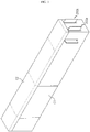
- FIG. 1 is a perspective view showing a battery module according to an embodiment of the present disclosure
- FIG. 2 is an exploded perspective view showing a battery module according to an embodiment of the present disclosure, from which only a module case is dissembled
- FIG. 3 is an enlarged exploded perspective view showing the battery module according to an embodiment of the present disclosure, from which a first bus bar, a second bus bar and a short-circuit unit are dissembled
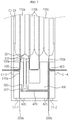
- FIG. 4 is a diagram showing a top surface of the battery module according to an embodiment of the present disclosure, before volume increase occurs.
- a battery module may include a module case C1, C2, C3, a battery cell 110a, 110b, 110c, a bus bar 200a, 200b, a short-circuit unit 300 and a cartridge 400.
- the module case C1, C2, C3 may accommodate components of the battery module according to the present disclosure therein and protect the battery module against impacts applied from the outside.
- the module case C1, C2, C3 may include a housing C1 for accommodating the battery cell 110a, 110b, 110c, the bus bar 200a, 200b and the short-circuit unit 300 in an inner space thereof, a cover C2 for covering an upper portion of the housing C1, and a clamp C3 for supporting the battery cell 110a, 110b, 110c in a right and left direction at the inside of the housing C1.
- the housing C1 and the cover C2 of the module case C1, C2, C3 may be sealed by welding.
- the housing C1 may include a bus bar hole C1-1, C1-2 formed in a front surface thereof so that the bus bar 200a, 200b accommodated in the inner space protrudes out toward the front.
- the bus bar 200a, 200b connected to the electrode lead of the battery cell 110a, 110b, 110c protrudes and exposes out of the module case C1, C2, C3, so that an external power source may be electrically connected to the bus bar 200a, 200b exposed out of the module case C1, C2, C3 to charge or discharge the battery cell 110a, 110b, 110c.
- the housing C1 may have support holes C1-3, C1-4 formed at right and left sides thereof so that the electrode lead of the battery cell 110a, 110b, 110c and the bus bar 200a, 200b contacted to face each other in the inner space may protrude out toward the right and left directions.
- the electrode lead of the battery cell 110a, 110b, 110c and the bus bar 200a, 200b contacted to face each other may be exposed to the outside, and may be supported inside the support holes C1-3, C1-4 to stably maintain their contact state even though being spaced apart from the ground.
- the clamp C3 may support the battery cell 110a, 110b, 110c in the right and left direction while surrounding the right and left sides and the bottom of the battery cell 110a, 110b, 110c. By doing so, when the volume of the battery cell 110a, 110b, 110c increases due to overcharge, the clamp C3 may apply a pressure to the right and left sides of the battery cell 110a, 110b, 110c to control swelling so that the volume increases in the front and rear direction.
- the clamp C3 may guide the volume of the battery cell 110a, 110b, 110c to be increased by overcharge in the front and rear direction where the electrode lead is formed. Accordingly, when the volume of the battery cell 110a, 110b, 110c according to the present disclosure increases due to overcharge, the front and rear surfaces of the battery cell 110a, 110b, 110c where the electrode lead is formed may be expanded.
- the module case C1, C2, C3 according to the present disclosure is not specially limited as long as the components of the battery module are accommodated in the inner space and protected thereby as described above, and various kinds of cases may be used for the battery module of the present disclosure.
- the battery cell 110a, 110b, 110c may be provided in plural, and the battery cells 110a, 110b, 110c may be stacked side by side in the right and left direction.
- the kind of the battery cell 110a, 110b, 110c is not specially limited, and various kinds of secondary batteries may be used for the battery module according to the present disclosure.
- the battery cell 110a, 110b, 110c may be a lithium ion battery, a lithium polymer battery, a nickel cadmium battery, a nickel hydride battery, a nickel zinc battery, or the like.
- the battery cell 110a, 110b, 110c may be a lithium secondary battery.
- the battery cell 110a, 110b, 110c may be classified into a pouch type, a cylindrical type, a rectangular type and the like, depending on its exterior.
- the battery cell 110a, 110b, 110c of the battery module according to the present disclosure may be a pouch-type secondary battery.
- each battery cell 110a, 110b, 110c is implemented using a pouch-type secondary battery, as shown in FIG. 2 , each battery cell 110a, 110b, 110c has broad surfaces at right and left sides thereof, and the broad surfaces of the battery cells 110a, 110b, 110c may be provided to face to each other.
- each battery cell 110a, 110b, 110c may include an electrode lead 120a, 120b that protrudes toward the front or is bent while protruding toward the front.
- the electrode lead 120a, 120b may include a positive electrode lead and a negative electrode lead.
- the positive electrode lead may be connected to a positive electrode plate of an electrode assembly
- the negative electrode lead may be connected to a negative electrode plate of the electrode assembly.
- the battery module according to the present disclosure may include a first battery cell 110a located at a leftmost side, a second battery cell 110b located at a rightmost side, and a plurality of third battery cells 110c located between the first battery cell 110a and the second battery cell 110b.
- the electrode leads of the first battery cell 110a and the second battery cell 110b may be disposed so that the electrode leads 120a, 120b having the same polarity are oriented in the same direction.
- the electrode leads of the first battery cell 110a and the second battery cell 110b may be formed to protrude toward the front and rear directions.
- the first battery cell 110a may be disposed so that the first electrode lead 120a having a positive polarity is oriented to the front direction
- the second battery cell 110b may be disposed so that the second electrode lead 120b having a negative polarity is oriented to the front direction.
- the first electrode lead 120a of the first battery cell 110a may be physically contacted and electrically connected to the first bus bar 200a, explained later. By doing so, the first electrode lead 120a may be electrically connected to a positive electrode of the external power source through the first bus bar 200a.
- the second electrode lead 120b of the second battery cell 110b may be physically contacted and electrically connected to the second bus bar 200b, explained later. By doing so, the second electrode lead 120b may be electrically connected to a negative electrode of the external power source through the second bus bar 200b.
- the first bus bar 200a may be a bus bar that is electrically connected to the first electrode lead 120a of the first battery cell 110a, among the bus bars 200a, 200b according to the present disclosure
- the second bus bar 200b may be a bus bar that is electrically connected to the second electrode lead 120b of the second battery cell 110b, among the bus bars 200a, 200b according to the present disclosure.
- connection structure between the first electrode lead 120a of the first battery cell 110a and the first bus bar 200a and the connection structure between the second electrode lead 120b of the second battery cell 110b and the second bus bar 200b according to the present disclosure will be described in detail.
- FIG. 5 is a diagram showing only a first battery cell, a second battery cell, a third battery cell, a first bus bar and a second bus bar of the battery module according to an embodiment of the present disclosure.
- the first electrode lead 120a of the first battery cell 110a may protrude toward the front from the first battery cell 110a and be bent about perpendicular toward the outside of the battery module to be in surface contact with the first bus bar 200a.
- the first bus bar 200a may include a first connection plate 210a, a first power plate 220a and a first protruding plate 230a.
- the first connection plate 210a has a plate shape and may be in surface contact with the first electrode lead 120a and be electrically connected thereto.
- the first connection plate 210a may extend in the same direction as the protruding direction of the first electrode lead 120a.
- the first connection plate 210a may be formed to extend in the same direction as the bending direction of the first electrode lead 120a that extends toward the front direction of the first battery cell 110a and is bent perpendicularly.
- first connection plate 210a may be physically contacted to the first electrode lead 120a by welding so as to be electrically connected thereto.
- a portion of the first connection plate 210a may be inserted into a support groove 420 ( FIG. 3 ) of a cartridge 400 ( FIG. 3 ), explained later, and be supported thereby.
- a portion of the first connection plate 210a may be exposed outwards through a support hole C1-3 ( FIG. 2 ) of a housing C1 ( FIG. 2 ).
- the first power plate 220a has the other end connected to one end of the first connection plate 210a, and may be formed to extend toward the front of the first battery cell 110a from one end of the first connection plate 210a. In other words, the other end of the first power plate 220a may perpendicular contact one end of the first connection plate 210a, and one end of the first power plate 220a may extend toward the front of the first battery cell 110a.
- one end of the first power plate 220a may be electrically connected to the positive electrode of the external power source.
- a portion of the first power plate 220a may be inserted into the support groove 420 ( FIG. 3 ) of the cartridge 400 ( FIG. 3 ), explained later, and be supported thereby, and the other portion may be exposed out through the bus bar hole C1-1 ( FIG. 2 ) of the housing C1 ( FIG. 2 ).
- the first protruding plate 230a may protrude toward the second bus bar 200b from the first power plate 220a.
- first protruding plate 230a may be formed to protrude approximately perpendicular to the first power plate 220a from the inner side of the first power plate 220a.
- first protruding plate 230a may be inserted into the support groove 420 ( FIG. 3 ) of the cartridge 400 ( FIG. 3 ), explained later, and be supported thereby.
- the first bus bar 200a may further include a fracturing portion 240a.
- the fracturing portion 240a may be formed at the first power plate 220a. More specifically, the fracturing portion 240a may be formed at a location of the first power plate 220a that is closer to the first battery cell 110a rather than the first protruding plate 230a.
- the fracturing portion 240a may be formed to have a cross section smaller than a cross section of the first connection plate 210a, the first power plate 220a and the first protruding plate 230a.
- the fracturing portion 240a formed at the first bus bar 200a may have a cross section smaller than an average cross section of the first bus bar 200a.
- the fracturing portion 240a is formed to have a cross section smaller than a cross section of the first connection plate 210a, the first power plate 220a and the first protruding plate 230a, resistance may be increased when a current flows.
- the fracturing portion 240a may be fractured since overcurrent flows at the first bus bar 200a to generate high-temperature resistance heat.
- the second electrode lead 120b of the second battery cell 110b protrudes toward the front from the second battery cell 110b and is bent at about a right angle in an outer direction of the battery module, namely in a direction opposite to the bending direction of the first electrode lead 120a of the first battery cell 110a, to make surface contact with the second bus bar 200b.
- the second bus bar 200b may include a second connection plate 210b, a second power plate 220b and a second protruding plate 230b.
- the second connection plate 210b has a plate shape and may be in surface contact with the second electrode lead 120b and electrically connected thereto.
- the second connection plate 210b may extend in the same direction as the protruding direction of the second electrode lead 120b.
- the second connection plate 210b may be formed to extend in the same direction as the bending direction of the second electrode lead 120b that extends toward the front of the second battery cell 110b and then is bent perpendicularly.
- the second connection plate 210b may be physically contacted to the second electrode lead 120b by welding and electrically connected thereto.
- a portion of the second connection plate 210b may be inserted into the support groove 420 ( FIG. 3 ) of the cartridge 400 ( FIG. 3 ), explained later, and be supported thereby.
- the second connection plate 210b may be exposed through a support hole C1-4 ( FIG. 2 ) of the housing C1 ( FIG. 2 ).
- the second power plate 220b has the other end connected to one end of the second connection plate 210b, and may extend toward the front of the second battery cell 110b from one end of the second connection plate 210b. In other words, the other end of the second power plate 220b may perpendicularly contact one end of the second connection plate 210b, and one end of the second power plate 220b may extend toward the front of the second battery cell 110b.
- one end of the second power plate 220b may be electrically connected to the negative electrode of the external power source.
- a portion of the second power plate 220b may be inserted into the support groove 420 ( FIG. 3 ) of the cartridge 400 ( FIG. 3 ), explained later, and be supported thereby, and the other portion may be exposed out through the bus bar hole C1-2 ( FIG. 2 ) of the housing C1 ( FIG. 2 ).
- the second protruding plate 230b may be formed to protrude toward the first bus bar 200a from the second power plate 220b.
- the second protruding plate 230b may be formed to protrude approximately perpendicular to the second power plate 220b from the inner side of the second power plate 220b.
- a portion of the second protruding plate 230b may be inserted into the support groove 420 ( FIG. 3 ) of the cartridge 400 ( FIG. 3 ), explained later, and be supported thereby.
- FIG. 6 is a diagram showing a side of the battery module according to an embodiment of the present disclosure after a fracturing portion is fractured.
- the fracturing portion 240a of the first bus bar 200a that electrically connect the first electrode lead 120a of the first battery cell 110a and the external power source may be fractured to stop charging.
- the fracturing portion 240a connecting the first connection plate 210a connected to the first electrode lead 120a of the first battery cell 110a and the first power plate 220a connected to the external power source may be fractured to stop charging.
- the first bus bar 200a and the second bus bar 200b may be electrically connected when the short-circuit unit 300, explained later, moves toward the first bus bar 200a and the second bus bar 200b so that a short-circuit terminal 322 provided at the short-circuit unit 300 simultaneously contacts the first bus bar 200a and the second bus bar 200b to be electrically connected.
- the short-circuit unit 300 may move toward the first bus bar 200a and the second bus bar 200b by receiving an expansive force that is generated by a volume increase of the first battery cell 110a due to overcharge. At this time, if a volume of another battery cell 110c adjacent to the first battery cell 110a increases, the short-circuit unit 300 may receive an expansive force from another battery cell 110c adjacent to the first battery cell 110a.
- the battery module according to the present disclosure may apply the expansive force generated by a volume increase due to overcharge of the first battery module 110a to the short-circuit unit 300 ( FIG. 3 ) to electrically connect the first bus bar 200a and the second bus bar 200b ( FIG. 3 ). Subsequently, as the fracturing portion 240a of the first bus bar 200a is fractured due to the short circuit of high current flowing at the first bus bar 200a and the second bus bar 200b ( FIG. 3 ), the battery module according to the present disclosure may stop charging to prevent the overcharge of the battery module from progressing.
- fracturing portion 240a of the battery module according to an embodiment of the present disclosure is formed at the first bus bar 200a
- a fracturing portion according to another embodiment of the present disclosure may be formed at the second bus bar
- a fracturing portion according to still another embodiment of the present disclosure may be formed at both the first bus bar and the second bus bar.
- the fracturing portion 240a may be formed to have a narrower width than the adjacent region as described above.
- the fracturing portion 240a may be made of a metal having a melting point lower than that of the adjacent region, and the fracturing portion 240a may adopt any configuration as long as it is able to function as a fuse.
- the short-circuit unit 300 may cause a short circuit by receiving an expansive force due to a volume increase of the first battery cell 110a to move toward the first bus bar 200a and the second bus bar 200b and contact the first bus bar 200a and the second bus bar 200b.
- the short-circuit unit 300 may include a slide bar 320 and a buffering member 310.
- the slide bar 320 may move toward the first bus bar 200a and the second bus bar 200b by contacting the first battery cell 110a at the other end thereof and receiving the expansive force.
- the slide bar 320 may have a semicylindrical contact portion 321 at the other end thereof.
- the surface of the contact portion 321 in contact with the first battery cell 110a may be a curved surface in order to constantly receive an expansive force generated in the plurality of directions from the first battery cell 110a.
- the slide bar 320 may include a placing portion provided at one end thereof so that the short-circuit terminal 322 contacting the first bus bar 200a and the second bus bar 200b is placed.
- the placing portion has a plate shape to make surface contact with the short-circuit terminal 322 having a plate shape, so that the placing portion may stably support the short-circuit terminal 322 when the short-circuit terminal 322 contacts the first bus bar 200a and the second bus bar 200b.
- One end and the other end of the buffering member 310 are respectively in contact with the contact portion 321 and the cartridge 400 so that the buffering member 310 is compressed by the slide bar 320 to absorb an impact when the slide bar 320 moves toward the first bus bar 200a and the second bus bar 200b.
- the buffering member 310 is disposed between the contact portion 321 and the cartridge 400 to prevent the short-circuit unit 300 from moving toward the first bus bar 200a and the second bus bar 200b.
- the expansive force due to the volume increase of the first bus bar 200a is not applied since no overcharge occurs in the battery module, it is possible to prevent an unnecessary short circuit from occurring at the first bus bar 200a and the second bus bar 200b.
- the buffering member 310 may be formed with a sponge structure or a spring structure, and the buffering member 310 is not limited as long as it is able to absorb an impact.
- FIG. 7 is a diagram showing the top surface of the battery module according to an embodiment of the present disclosure, after volume increase occurs.
- the volume of the first battery cell 110a may increase. At this time, if the volume of the first battery cell 110a increases, the contact portion 321 of the slide bar 320 may receive an expansive force from the first battery cell 110a.
- the slide bar 320 may move in a direction (a) toward the first bus bar 200a and the second bus bar 200b due to the expansive force applied to the contact portion 321.
- the short-circuit terminal 322 placed on the placing portion of the slide bar 320 may contact the first bus bar 200a and the second bus bar 200b to electrically connect the first bus bar 200a and the second bus bar 200b.
- the circuit including the short-circuit terminal 322, the first bus bar 200a and the second bus bar 200b may form a short circuit.
- the short-circuit terminal 322 may be made of a conductive material.
- the short-circuit unit 300 may receive an expansive force from the first battery cell 110a to move toward the first bus bar 200a and the second bus bar 200b and electrically connect the first bus bar 200a and the second bus bar 200b, thereby generating a short circuit.
- FIG. 8 is an equivalent circuit diagram before overcharge occurs at the battery module according to an embodiment of the present disclosure
- FIG. 9 is an equivalent circuit diagram just after a short-circuit unit moves after overcharge occurs at the battery module according to an embodiment of the present disclosure
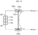
- FIG. 10 is an equivalent circuit diagram after the short-circuit unit moves to fracture fracturing portion after overcharge occurs at the battery module according to an embodiment of the present disclosure.
- the volume of the plurality of battery cells 110a, 110b, 110c does not increase, and thus the first bus bar 200a and the second bus bar 200b may not cause an electrical short circuit.
- the short-circuit unit 300 may receive an expansive force from the first battery cell 110a to move to the first bus bar 200a and the second bus bar 200b. Accordingly, the short-circuit terminal of the short-circuit unit 300 may contact the first bus bar 200a and the second bus bar 200b and electrically connect the first bus bar 200a and the second bus bar 200b to generate a short circuit.
- a short circuit including the short-circuit unit 300, the first bus bar 200a and the second bus bar 200b is formed so that a high current I may flow.
- the fracturing portion 240a having great resistance due to a small cross section generates high-temperature resistance heat and thus is fractured, thereby cutting the power supplied from the external power source to the battery module and thus preventing the overcharge.
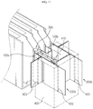
- FIG. 11 is a perspective view showing an inside of a cartridge of the battery module according to an embodiment of the present disclosure.
- the cartridge 400 may accommodate or support a part of the first electrode lead 120a of the first battery cell 110a, the second electrode lead 120b of the second battery cell 110b, the first bus bar 200a, the second bus bar 200b and the short-circuit unit 300.
- the cartridge 400 may support the first electrode lead 120a of the first battery cell 110a and the first bus bar 200a, which are in surface contact with each other to be electrically connected, at a lower portion thereof, and may support the second electrode lead 120b of the second battery cell 110b and the second bus bar 200b, which are in surface contact with each other to be electrically connected, at a lower portion thereof.
- the cartridge 400 may have a support groove 420 formed to have a shape corresponding to the bending shape of the first electrode lead 120a of the first battery cell 110a, the second electrode lead 120b of the second battery cell 110b, the first bus bar 200a and the second bus bar 200b.
- the cartridge 400 may have an accommodation portion 410 formed therein with a shape corresponding to an appearance of the short-circuit unit 300 and an appearance of the short-circuit unit 300 to accommodate the short-circuit unit 300 therein.
- the accommodation portion 410 of the cartridge 400 may be formed to correspond to the movement of the short-circuit unit 300.
- the accommodation portion 410 of the cartridge 400 may be formed to correspond to a location before the short-circuit unit 300 receives the expansive force and a location after the short-circuit unit 300 receives the expansive force.
- accommodation portion 410 may be formed at the inside of the cartridge 400 to have a shape corresponding to an appearance of the short-circuit unit 300.
- the battery module according to the present disclosure may improve the stability of the battery module by fracturing the first bus bar accurately when the battery cell abnormally expands to cut off the power supplied from the external voltage source and thus prevent the overcharge of the battery module.
- a battery pack according to the present disclosure includes at least one battery module as described above.
- the battery pack may further include a case for accommodating the battery module, and various devices for controlling charge/discharge of the battery module such as a battery management system (BMS), a current sensor and a fuse.
- BMS battery management system
- the battery pack according to an embodiment of the present disclosure may include the first bus bar, the second bus bar, the short-circuit unit and the cartridge at each battery module to cut off the power supplied from the external voltage source by fracturing the first bus bar when the battery cell abnormally expands, so that overcharge is prevented for each battery module.
- the battery module according to the present disclosure may be applied to a vehicle such as an electric vehicle and a hybrid vehicle. That is, the vehicle according to the present disclosure may include the battery module of the present disclosure.
Landscapes
- Chemical & Material Sciences (AREA)
- General Chemical & Material Sciences (AREA)
- Electrochemistry (AREA)
- Chemical Kinetics & Catalysis (AREA)
- Engineering & Computer Science (AREA)
- Mechanical Engineering (AREA)
- Transportation (AREA)
- Life Sciences & Earth Sciences (AREA)
- Power Engineering (AREA)
- Sustainable Energy (AREA)
- Sustainable Development (AREA)
- Combustion & Propulsion (AREA)
- Battery Mounting, Suspending (AREA)
- Connection Of Batteries Or Terminals (AREA)
Abstract
Description
- The present disclosure relates to a battery module, and a battery pack and a vehicle including the same, and more particularly, to a battery module having improved stability by preventing overcharge of the battery module, and a battery pack and a vehicle including the same.
- The present application claims priority to Korean Patent Application No.
10-2017-0081350 filed on June 27, 2017 - Recently, the demand for portable electronic products such as notebook computers, video cameras and portable telephones has increased sharply, and electric vehicles, energy storage batteries, robots, satellites and the like have been developed in earnest. Accordingly, high-performance secondary batteries allowing repeated charging and discharging are being actively studied.
- Secondary batteries commercially available at the present include nickel-cadmium batteries, nickel hydrogen batteries, nickel-zinc batteries, lithium secondary batteries and the like. Among them, the lithium secondary batteries are in the limelight since they have almost no memory effect compared to nickel-based secondary batteries and also have very low self-discharging rate and high energy density.
- The lithium secondary battery mainly uses lithium-based oxide and carbonaceous material as a positive electrode active material and a negative electrode active material, respectively. The lithium secondary battery includes an electrode assembly in which a positive electrode plate and a negative electrode plate respectively coated with a positive electrode active material and a negative electrode active material are disposed with a separator being interposed therebetween, and an exterior, namely a battery case, in which the electrode assembly is accommodated and sealed together with an electrolyte.
- Generally, a lithium secondary battery may be classified into a can-type secondary battery in which an electrode assembly is included in a metal can and a pouch-type secondary battery in which an electrode assembly is included in a pouch made of aluminum laminate sheets, depending on the shape of an exterior.
- In recent years, secondary batteries have been widely used not only in small-sized devices such as portable electronic devices but also in medium-sized and large-sized devices such as vehicles and power storage devices. In particular, as carbon energy is getting depleted and the interest in the environment is increasing, the attention is focused on hybrid electric vehicles and electric vehicles around the world including the US, Europe, Japan and Korea. The most important component of the hybrid electric vehicles and electric vehicles is a battery pack that gives a drive power to a vehicle motor. Since the hybrid electric vehicle or electric vehicle is able to obtain a driving force of the vehicle through charging and discharging of the battery pack, the fuel efficiency is higher than that of a vehicle using only an engine, and pollutants may be reduced or substantially eliminated. For these reasons, the hybrid electric vehicles and electric vehicles are used more and more. In addition, the battery pack of the hybrid electric vehicle or electric vehicle includes a plurality of secondary batteries, and the plurality of secondary batteries are connected in series and in parallel to improve capacity and power.
- The secondary battery has excellent electrical characteristics, but in the abnormal operating conditions such as overcharge, overdischarge, exposure to high temperature and electrical short circuit, the decomposition reaction of an active material, an electrolyte and the like of the battery is caused to generate heat and gas, thereby resulting in a so-called swelling phenomenon where the secondary battery swells. The swelling phenomenon accelerates the decomposition reaction, which may cause explosion and ignition of the secondary battery due to thermal runaway.
- Thus, the secondary battery includes a safety system such as a protection circuit for cutting a current at overcharge, overdischarge or overcurrent, a positive temperature coefficient (PTC) element for cutting a current by greatly increasing resistance when temperature rises, a safety vent for cutting a current or venting a gas when pressure increases due to gas generation.
- In particular, in the conventional art, in order to ensure the safety of the battery pack even if a swelling phenomenon occurs, an electrical connecting member that is cut off by a physical change when the volume of secondary batteries expands has been studied.
- However, even if the electrical connecting member is used, it is difficult to surely cut the current of the secondary battery when the secondary batteries are expanded over a certain volume.
- In addition, the secondary battery repeats expansion and contraction even when it is in a normal operating state, not in an abnormal operating state, and thus the current of the secondary battery may be cut even in a normal operation range, which may deteriorate the operation reliability.
- The present disclosure is directed to providing a battery module, which may prevent overcharge by fracturing a fracturing portion formed at a first bus bar since a short-circuit unit moves toward a first bus bar and a second bus bar and comes into contact thereto by receiving an expansive force due to the volume increase of a first battery cell and another battery cell adjacent to the first battery cell to electrically connect the first bus bar and the second bus bar and thus cause a short circuit, and to providing a battery pack and a vehicle including the battery module.
- These and other objects and advantages of the present disclosure may be understood from the following detailed description and will become more fully apparent from the exemplary embodiments of the present disclosure. Also, it will be easily understood that the objects and advantages of the present disclosure may be realized by the means shown in the appended claims and combinations thereof.
- In one aspect of the present disclosure, there is provided a battery module, comprising: a first bus bar electrically connected to a first electrode lead of a first battery cell; a second bus bar electrically connected to a second electrode lead of a second battery cell; a short-circuit unit configured to move toward the first bus bar and the second bus bar by receiving an expansive force due to a volume increase of the first battery cell and another battery cell adjacent to the first battery cell so that the first bus bar and the second bus bar are electrically connected to generate a short circuit; and a cartridge configured to accommodate or support at least a portion of the first electrode lead, the second electrode lead, the first bus bar, the second bus bar and the short-circuit unit.
- Preferably, the short-circuit unit may include: a slide bar having a contact portion provided at the other end thereof and in contact with one end of the first battery cell to receive the expansive force, and a placing portion provided at one end thereof so that a short-circuit terminal is placed thereon; and a buffering member having one end and the other end that are respectively in contact with the contact portion and the cartridge, so as to be compressed by the slide bar to absorb an impact when the slide bar moves toward the first bus bar and the second bus bar.
- Preferably, when the volume of the first battery cell and another battery cell adjacent to the first battery cell increases, the slide bar may receive the expansive force through the contact portion to move toward the first bus bar and the second bus bar.
- Preferably, the short-circuit terminal may be in contact with the first bus bar and the second bus bar and electrically connect the first bus bar and the second bus bar to generate a short circuit.
- Preferably, the short-circuit terminal may be made of a conductive material.
- Preferably, the first bus bar may include: a first connection plate contacted and electrically connected to the first electrode lead; a first power plate formed to extend toward the front of the first battery cell from the first connection plate and electrically connected to an external power source; and a first protruding plate formed to protrude toward the second bus bar from the first power plate.
- Preferably, the second bus bar may include: a second connection plate contacted and electrically connected to the second electrode lead; a second power plate formed to extend toward the front of the second battery cell from the second connection plate and electrically connected to the external power source; and a second protruding plate formed to protrude toward the first bus bar from the second power plate.
- Preferably, at least one of the first bus bar and the second bus bar may further include a fracturing portion that is fractured to cut an electric connection to the outside when the short circuit is generated.
- Preferably, the fracturing portion may be formed to have a cross section smaller than an average cross section of the first bus bar or the second bus bar.
- Preferably, the fracturing portion may be formed in at least one of the first power plate of the first bus bar and the second power plate of the second bus bar.
- Preferably, the cartridge may have an accommodation portion formed therein with a shape corresponding to an appearance of the short-circuit unit to accommodate the short-circuit unit therein.
- Preferably, the cartridge may support at least a portion of each of the first electrode lead and the first bus bar that are in surface contact with each other to be electrically connected, and support at least a portion of each of the second electrode lead and the second bus bar that are in surface contact with each other to be electrically connected.
- A battery pack according to the present disclosure may include the battery module.
- A vehicle according to the present disclosure may include the battery module.
- According to the present disclosure, a first bus bar and a second bus bar are electrically connected by means of an expansive force due to the volume increase of a first battery cell and another battery cell adjacent to the first battery cell to cause a short circuit, and thus a fracturing portion formed at any one of the first bus bar and the second bus bar is fractured to prevent overcharge of the battery module, thereby improving the stability of the battery module.
-
-
FIG. 1 is a perspective view showing a battery module according to an embodiment of the present disclosure. -
FIG. 2 is an exploded perspective view showing a battery module according to an embodiment of the present disclosure, from which only a module case is dissembled. -
FIG. 3 is an enlarged exploded perspective view showing the battery module according to an embodiment of the present disclosure, from which a first bus bar, a second bus bar and a short-circuit unit are dissembled. -
FIG. 4 is a diagram showing a top surface of the battery module according to an embodiment of the present disclosure, before volume increase occurs. -
FIG. 5 is a diagram showing only a first battery cell, a second battery cell, a third battery cell, a first bus bar and a second bus bar of the battery module according to an embodiment of the present disclosure. -
FIG. 6 is a diagram showing a side of the battery module according to an embodiment of the present disclosure after a fracturing portion is fractured. -
FIG. 7 is a diagram showing the top surface of the battery module according to an embodiment of the present disclosure, after volume increase occurs. -
FIG. 8 is an equivalent circuit diagram before overcharge occurs at the battery module according to an embodiment of the present disclosure. -
FIG. 9 is an equivalent circuit diagram just after a short-circuit unit moves after overcharge occurs at the battery module according to an embodiment of the present disclosure. -
FIG. 10 is an equivalent circuit diagram after the short-circuit unit moves to fracture fracturing portion after overcharge occurs at the battery module according to an embodiment of the present disclosure. -
FIG. 11 is a perspective view showing an inside of a cartridge of the battery module according to an embodiment of the present disclosure. - The above objects, features and advantages will be described in detail below with reference to the accompanying drawings, so that those skilled in the art to which the present disclosure belongs can easily implement the technical idea of the present disclosure. In the explanations of the present disclosure, if it is deemed that any specific explanation of the related technology can unnecessarily obscure the gist of the present disclosure, the detailed explanation may be omitted. Hereinafter, a preferred embodiment according to the present disclosure will be described in detail with reference to the accompanying drawings. In the drawings, the same reference numerals are used to indicate the same or similar components.
-
FIG. 1 is a perspective view showing a battery module according to an embodiment of the present disclosure,FIG. 2 is an exploded perspective view showing a battery module according to an embodiment of the present disclosure, from which only a module case is dissembled,FIG. 3 is an enlarged exploded perspective view showing the battery module according to an embodiment of the present disclosure, from which a first bus bar, a second bus bar and a short-circuit unit are dissembled, andFIG. 4 is a diagram showing a top surface of the battery module according to an embodiment of the present disclosure, before volume increase occurs. - Referring to
FIGS. 1 to 4 , a battery module according to an embodiment of the present disclosure may include a module case C1, C2, C3, abattery cell bus bar circuit unit 300 and acartridge 400. - The module case C1, C2, C3 may accommodate components of the battery module according to the present disclosure therein and protect the battery module against impacts applied from the outside.
- More specifically, the module case C1, C2, C3 may include a housing C1 for accommodating the
battery cell bus bar circuit unit 300 in an inner space thereof, a cover C2 for covering an upper portion of the housing C1, and a clamp C3 for supporting thebattery cell - The housing C1 and the cover C2 of the module case C1, C2, C3 may be sealed by welding.
- Meanwhile, the housing C1 may include a bus bar hole C1-1, C1-2 formed in a front surface thereof so that the
bus bar bus bar battery cell bus bar battery cell - In addition, the housing C1 may have support holes C1-3, C1-4 formed at right and left sides thereof so that the electrode lead of the
battery cell bus bar battery cell bus bar - Meanwhile, the clamp C3 may support the
battery cell battery cell battery cell battery cell - In other words, the clamp C3 may guide the volume of the
battery cell battery cell battery cell - The module case C1, C2, C3 according to the present disclosure is not specially limited as long as the components of the battery module are accommodated in the inner space and protected thereby as described above, and various kinds of cases may be used for the battery module of the present disclosure.
- The
battery cell battery cells - The kind of the
battery cell battery cell battery cell - Meanwhile, the
battery cell battery cell - If the
battery cell FIG. 2 , eachbattery cell battery cells battery cell electrode lead - The
electrode lead - Meanwhile, the battery module according to the present disclosure may include a
first battery cell 110a located at a leftmost side, asecond battery cell 110b located at a rightmost side, and a plurality ofthird battery cells 110c located between thefirst battery cell 110a and thesecond battery cell 110b. At this time, the electrode leads of thefirst battery cell 110a and thesecond battery cell 110b may be disposed so that the electrode leads 120a, 120b having the same polarity are oriented in the same direction. In addition, the electrode leads of thefirst battery cell 110a and thesecond battery cell 110b may be formed to protrude toward the front and rear directions. - More specifically, as shown in
FIG. 3 , thefirst battery cell 110a may be disposed so that thefirst electrode lead 120a having a positive polarity is oriented to the front direction, and thesecond battery cell 110b may be disposed so that thesecond electrode lead 120b having a negative polarity is oriented to the front direction. - Meanwhile, the
first electrode lead 120a of thefirst battery cell 110a may be physically contacted and electrically connected to thefirst bus bar 200a, explained later. By doing so, thefirst electrode lead 120a may be electrically connected to a positive electrode of the external power source through thefirst bus bar 200a. - The
second electrode lead 120b of thesecond battery cell 110b may be physically contacted and electrically connected to thesecond bus bar 200b, explained later. By doing so, thesecond electrode lead 120b may be electrically connected to a negative electrode of the external power source through thesecond bus bar 200b. - Here, the
first bus bar 200a may be a bus bar that is electrically connected to thefirst electrode lead 120a of thefirst battery cell 110a, among thebus bars second bus bar 200b may be a bus bar that is electrically connected to thesecond electrode lead 120b of thesecond battery cell 110b, among thebus bars - Hereinafter, the connection structure between the
first electrode lead 120a of thefirst battery cell 110a and thefirst bus bar 200a and the connection structure between thesecond electrode lead 120b of thesecond battery cell 110b and thesecond bus bar 200b according to the present disclosure will be described in detail. -
FIG. 5 is a diagram showing only a first battery cell, a second battery cell, a third battery cell, a first bus bar and a second bus bar of the battery module according to an embodiment of the present disclosure. - Referring to
FIG. 5 further, thefirst electrode lead 120a of thefirst battery cell 110a may protrude toward the front from thefirst battery cell 110a and be bent about perpendicular toward the outside of the battery module to be in surface contact with thefirst bus bar 200a. - More specifically, the
first bus bar 200a may include afirst connection plate 210a, afirst power plate 220a and a first protrudingplate 230a. - The
first connection plate 210a has a plate shape and may be in surface contact with thefirst electrode lead 120a and be electrically connected thereto. - At this time, the
first connection plate 210a may extend in the same direction as the protruding direction of thefirst electrode lead 120a. In other words, thefirst connection plate 210a may be formed to extend in the same direction as the bending direction of thefirst electrode lead 120a that extends toward the front direction of thefirst battery cell 110a and is bent perpendicularly. - Meanwhile, the
first connection plate 210a may be physically contacted to thefirst electrode lead 120a by welding so as to be electrically connected thereto. - At this time, in a state where the
first electrode lead 120a of thefirst battery cell 110a and thefirst bus bar 200a are in surface contact and thus electrically connected to each other, a portion of thefirst connection plate 210a may be inserted into a support groove 420 (FIG. 3 ) of a cartridge 400 (FIG. 3 ), explained later, and be supported thereby. - In addition, in a state where the
first electrode lead 120a of thefirst battery cell 110a and thefirst bus bar 200a are in surface contact and thus electrically connected to each other, a portion of thefirst connection plate 210a may be exposed outwards through a support hole C1-3 (FIG. 2 ) of a housing C1 (FIG. 2 ). - The
first power plate 220a has the other end connected to one end of thefirst connection plate 210a, and may be formed to extend toward the front of thefirst battery cell 110a from one end of thefirst connection plate 210a. In other words, the other end of thefirst power plate 220a may perpendicular contact one end of thefirst connection plate 210a, and one end of thefirst power plate 220a may extend toward the front of thefirst battery cell 110a. - In addition, one end of the
first power plate 220a may be electrically connected to the positive electrode of the external power source. - At this time, a portion of the
first power plate 220a may be inserted into the support groove 420 (FIG. 3 ) of the cartridge 400 (FIG. 3 ), explained later, and be supported thereby, and the other portion may be exposed out through the bus bar hole C1-1 (FIG. 2 ) of the housing C1 (FIG. 2 ). - The first protruding
plate 230a may protrude toward thesecond bus bar 200b from thefirst power plate 220a. - More specifically, the first protruding
plate 230a may be formed to protrude approximately perpendicular to thefirst power plate 220a from the inner side of thefirst power plate 220a. - In addition, a portion of the first protruding
plate 230a may be inserted into the support groove 420 (FIG. 3 ) of the cartridge 400 (FIG. 3 ), explained later, and be supported thereby. - Meanwhile, the
first bus bar 200a may further include a fracturingportion 240a. - As shown in
FIG. 3 , the fracturingportion 240a may be formed at thefirst power plate 220a. More specifically, the fracturingportion 240a may be formed at a location of thefirst power plate 220a that is closer to thefirst battery cell 110a rather than the first protrudingplate 230a. - Meanwhile, the fracturing
portion 240a may be formed to have a cross section smaller than a cross section of thefirst connection plate 210a, thefirst power plate 220a and the first protrudingplate 230a. In other words, the fracturingportion 240a formed at thefirst bus bar 200a may have a cross section smaller than an average cross section of thefirst bus bar 200a. - Since the fracturing
portion 240a is formed to have a cross section smaller than a cross section of thefirst connection plate 210a, thefirst power plate 220a and the first protrudingplate 230a, resistance may be increased when a current flows. - Accordingly, if the
first bus bar 200a and thesecond bus bar 200b are electrically connected to form a short circuit among thefirst bus bar 200a, thesecond bus bar 200b and the external power source, the fracturingportion 240a may be fractured since overcurrent flows at thefirst bus bar 200a to generate high-temperature resistance heat. - The
second electrode lead 120b of thesecond battery cell 110b protrudes toward the front from thesecond battery cell 110b and is bent at about a right angle in an outer direction of the battery module, namely in a direction opposite to the bending direction of thefirst electrode lead 120a of thefirst battery cell 110a, to make surface contact with thesecond bus bar 200b. - More specifically, the
second bus bar 200b may include asecond connection plate 210b, asecond power plate 220b and a secondprotruding plate 230b. - The
second connection plate 210b has a plate shape and may be in surface contact with thesecond electrode lead 120b and electrically connected thereto. - At this time, the
second connection plate 210b may extend in the same direction as the protruding direction of thesecond electrode lead 120b. In other words, thesecond connection plate 210b may be formed to extend in the same direction as the bending direction of thesecond electrode lead 120b that extends toward the front of thesecond battery cell 110b and then is bent perpendicularly. - Meanwhile, the
second connection plate 210b may be physically contacted to thesecond electrode lead 120b by welding and electrically connected thereto. - At this time, in a state where the
second electrode lead 120b of thesecond battery cell 110b and thesecond bus bar 200b are in surface contact and thus electrically connected to each other, a portion of thesecond connection plate 210b may be inserted into the support groove 420 (FIG. 3 ) of the cartridge 400 (FIG. 3 ), explained later, and be supported thereby. - In addition, in a state where the
second electrode lead 120b of thesecond battery cell 110b and thesecond bus bar 200b are in surface contact and thus electrically connected to each other, thesecond connection plate 210b may be exposed through a support hole C1-4 (FIG. 2 ) of the housing C1 (FIG. 2 ). - The
second power plate 220b has the other end connected to one end of thesecond connection plate 210b, and may extend toward the front of thesecond battery cell 110b from one end of thesecond connection plate 210b. In other words, the other end of thesecond power plate 220b may perpendicularly contact one end of thesecond connection plate 210b, and one end of thesecond power plate 220b may extend toward the front of thesecond battery cell 110b. - In addition, one end of the
second power plate 220b may be electrically connected to the negative electrode of the external power source. - At this time, a portion of the
second power plate 220b may be inserted into the support groove 420 (FIG. 3 ) of the cartridge 400 (FIG. 3 ), explained later, and be supported thereby, and the other portion may be exposed out through the bus bar hole C1-2 (FIG. 2 ) of the housing C1 (FIG. 2 ). - The second
protruding plate 230b may be formed to protrude toward thefirst bus bar 200a from thesecond power plate 220b. - More specifically, the second protruding
plate 230b may be formed to protrude approximately perpendicular to thesecond power plate 220b from the inner side of thesecond power plate 220b. - In addition, a portion of the second protruding
plate 230b may be inserted into the support groove 420 (FIG. 3 ) of the cartridge 400 (FIG. 3 ), explained later, and be supported thereby. -
FIG. 6 is a diagram showing a side of the battery module according to an embodiment of the present disclosure after a fracturing portion is fractured. - Referring to
FIG. 6 further, in the battery module according to the present disclosure, if thefirst bus bar 200a and thesecond bus bar 200b are electrically connected to generate a short circuit, as shown inFIG. 6 , the fracturingportion 240a of thefirst bus bar 200a that electrically connect thefirst electrode lead 120a of thefirst battery cell 110a and the external power source may be fractured to stop charging. - In other words, if the
first bus bar 200a and thesecond bus bar 200b are electrically connected to generate a short circuit, the fracturingportion 240a connecting thefirst connection plate 210a connected to thefirst electrode lead 120a of thefirst battery cell 110a and thefirst power plate 220a connected to the external power source may be fractured to stop charging. - Here, the
first bus bar 200a and thesecond bus bar 200b may be electrically connected when the short-circuit unit 300, explained later, moves toward thefirst bus bar 200a and thesecond bus bar 200b so that a short-circuit terminal 322 provided at the short-circuit unit 300 simultaneously contacts thefirst bus bar 200a and thesecond bus bar 200b to be electrically connected. In addition, the short-circuit unit 300 may move toward thefirst bus bar 200a and thesecond bus bar 200b by receiving an expansive force that is generated by a volume increase of thefirst battery cell 110a due to overcharge. At this time, if a volume of anotherbattery cell 110c adjacent to thefirst battery cell 110a increases, the short-circuit unit 300 may receive an expansive force from anotherbattery cell 110c adjacent to thefirst battery cell 110a. - Hereinafter, only the case where the volume of the
first battery cell 110a increases will be described. However, it should be noted that an expansive force can be applied to the short-circuit unit 300 not only when the volume of thefirst battery cell 110a increases but also when the volume of anotherbattery cell 110c adjacent to thefirst battery cell 110a increases. - The battery module according to the present disclosure may apply the expansive force generated by a volume increase due to overcharge of the
first battery module 110a to the short-circuit unit 300 (FIG. 3 ) to electrically connect thefirst bus bar 200a and thesecond bus bar 200b (FIG. 3 ). Subsequently, as the fracturingportion 240a of thefirst bus bar 200a is fractured due to the short circuit of high current flowing at thefirst bus bar 200a and thesecond bus bar 200b (FIG. 3 ), the battery module according to the present disclosure may stop charging to prevent the overcharge of the battery module from progressing. - Meanwhile, even though it is illustrated that the fracturing
portion 240a of the battery module according to an embodiment of the present disclosure is formed at thefirst bus bar 200a, a fracturing portion according to another embodiment of the present disclosure may be formed at the second bus bar, and a fracturing portion according to still another embodiment of the present disclosure may be formed at both the first bus bar and the second bus bar. - In addition, the fracturing
portion 240a may be formed to have a narrower width than the adjacent region as described above. However, without being limited thereto, the fracturingportion 240a may be made of a metal having a melting point lower than that of the adjacent region, and the fracturingportion 240a may adopt any configuration as long as it is able to function as a fuse. - Hereinafter, the short-
circuit unit 300 will be described in detail. - The short-
circuit unit 300 may cause a short circuit by receiving an expansive force due to a volume increase of thefirst battery cell 110a to move toward thefirst bus bar 200a and thesecond bus bar 200b and contact thefirst bus bar 200a and thesecond bus bar 200b. - To this end, the short-
circuit unit 300 may include aslide bar 320 and abuffering member 310. - The
slide bar 320 may move toward thefirst bus bar 200a and thesecond bus bar 200b by contacting thefirst battery cell 110a at the other end thereof and receiving the expansive force. To this end, theslide bar 320 may have asemicylindrical contact portion 321 at the other end thereof. The surface of thecontact portion 321 in contact with thefirst battery cell 110a may be a curved surface in order to constantly receive an expansive force generated in the plurality of directions from thefirst battery cell 110a. - Meanwhile, the
slide bar 320 may include a placing portion provided at one end thereof so that the short-circuit terminal 322 contacting thefirst bus bar 200a and thesecond bus bar 200b is placed. - The placing portion has a plate shape to make surface contact with the short-
circuit terminal 322 having a plate shape, so that the placing portion may stably support the short-circuit terminal 322 when the short-circuit terminal 322 contacts thefirst bus bar 200a and thesecond bus bar 200b. - One end and the other end of the buffering
member 310 are respectively in contact with thecontact portion 321 and thecartridge 400 so that the bufferingmember 310 is compressed by theslide bar 320 to absorb an impact when theslide bar 320 moves toward thefirst bus bar 200a and thesecond bus bar 200b. - In addition, the buffering
member 310 is disposed between thecontact portion 321 and thecartridge 400 to prevent the short-circuit unit 300 from moving toward thefirst bus bar 200a and thesecond bus bar 200b. Thus, if the expansive force due to the volume increase of thefirst bus bar 200a is not applied since no overcharge occurs in the battery module, it is possible to prevent an unnecessary short circuit from occurring at thefirst bus bar 200a and thesecond bus bar 200b. - The buffering
member 310 may be formed with a sponge structure or a spring structure, and thebuffering member 310 is not limited as long as it is able to absorb an impact. -
FIG. 7 is a diagram showing the top surface of the battery module according to an embodiment of the present disclosure, after volume increase occurs. - Referring to
FIG. 7 further, if the battery module is overcharged, the volume of thefirst battery cell 110a may increase. At this time, if the volume of thefirst battery cell 110a increases, thecontact portion 321 of theslide bar 320 may receive an expansive force from thefirst battery cell 110a. - After that, the
slide bar 320 may move in a direction (a) toward thefirst bus bar 200a and thesecond bus bar 200b due to the expansive force applied to thecontact portion 321. Finally, the short-circuit terminal 322 placed on the placing portion of theslide bar 320 may contact thefirst bus bar 200a and thesecond bus bar 200b to electrically connect thefirst bus bar 200a and thesecond bus bar 200b. - By doing so, the circuit including the short-
circuit terminal 322, thefirst bus bar 200a and thesecond bus bar 200b may form a short circuit. - For this, the short-
circuit terminal 322 may be made of a conductive material. - As described above, in the battery module according to an embodiment of the present disclosure, if the volume of the
first battery cell 110a increases due to the overcharge, the short-circuit unit 300 may receive an expansive force from thefirst battery cell 110a to move toward thefirst bus bar 200a and thesecond bus bar 200b and electrically connect thefirst bus bar 200a and thesecond bus bar 200b, thereby generating a short circuit. - Hereinafter, the circuit configuration according to the movement of the short-circuit unit of the battery module according to an embodiment of the present disclosure will be described.
-
FIG. 8 is an equivalent circuit diagram before overcharge occurs at the battery module according to an embodiment of the present disclosure,FIG. 9 is an equivalent circuit diagram just after a short-circuit unit moves after overcharge occurs at the battery module according to an embodiment of the present disclosure, andFIG. 10 is an equivalent circuit diagram after the short-circuit unit moves to fracture fracturing portion after overcharge occurs at the battery module according to an embodiment of the present disclosure. - Referring to
FIGS. 8 to 10 , if the battery module according to the present disclosure is not overcharged but operates normally, as shown inFIG. 8 , the volume of the plurality ofbattery cells first bus bar 200a and thesecond bus bar 200b may not cause an electrical short circuit. - However, as shown in
FIG. 9 , if the battery module according to the present disclosure is overcharged to increase the volume of thefirst battery cell 110a, the short-circuit unit 300 may receive an expansive force from thefirst battery cell 110a to move to thefirst bus bar 200a and thesecond bus bar 200b. Accordingly, the short-circuit terminal of the short-circuit unit 300 may contact thefirst bus bar 200a and thesecond bus bar 200b and electrically connect thefirst bus bar 200a and thesecond bus bar 200b to generate a short circuit. - By doing so, a short circuit including the short-
circuit unit 300, thefirst bus bar 200a and thesecond bus bar 200b is formed so that a high current I may flow. - After that, if the high current I flows continuously at the
first bus bar 200a, as shown inFIG. 10 , the fracturingportion 240a having great resistance due to a small cross section generates high-temperature resistance heat and thus is fractured, thereby cutting the power supplied from the external power source to the battery module and thus preventing the overcharge. -
FIG. 11 is a perspective view showing an inside of a cartridge of the battery module according to an embodiment of the present disclosure. - Referring to
FIG. 11 , thecartridge 400 may accommodate or support a part of thefirst electrode lead 120a of thefirst battery cell 110a, thesecond electrode lead 120b of thesecond battery cell 110b, thefirst bus bar 200a, thesecond bus bar 200b and the short-circuit unit 300. - More specifically, the
cartridge 400 may support thefirst electrode lead 120a of thefirst battery cell 110a and thefirst bus bar 200a, which are in surface contact with each other to be electrically connected, at a lower portion thereof, and may support thesecond electrode lead 120b of thesecond battery cell 110b and thesecond bus bar 200b, which are in surface contact with each other to be electrically connected, at a lower portion thereof. - For this, the
cartridge 400 may have asupport groove 420 formed to have a shape corresponding to the bending shape of thefirst electrode lead 120a of thefirst battery cell 110a, thesecond electrode lead 120b of thesecond battery cell 110b, thefirst bus bar 200a and thesecond bus bar 200b. - Meanwhile, the
cartridge 400 may have anaccommodation portion 410 formed therein with a shape corresponding to an appearance of the short-circuit unit 300 and an appearance of the short-circuit unit 300 to accommodate the short-circuit unit 300 therein. - At this time, the
accommodation portion 410 of thecartridge 400 may be formed to correspond to the movement of the short-circuit unit 300. - In other words, the
accommodation portion 410 of thecartridge 400 may be formed to correspond to a location before the short-circuit unit 300 receives the expansive force and a location after the short-circuit unit 300 receives the expansive force. - In addition, the
accommodation portion 410 may be formed at the inside of thecartridge 400 to have a shape corresponding to an appearance of the short-circuit unit 300. - The battery module according to the present disclosure may improve the stability of the battery module by fracturing the first bus bar accurately when the battery cell abnormally expands to cut off the power supplied from the external voltage source and thus prevent the overcharge of the battery module.
- Meanwhile, a battery pack according to the present disclosure includes at least one battery module as described above. At this time, in addition to the battery module, the battery pack may further include a case for accommodating the battery module, and various devices for controlling charge/discharge of the battery module such as a battery management system (BMS), a current sensor and a fuse. In particular, the battery pack according to an embodiment of the present disclosure may include the first bus bar, the second bus bar, the short-circuit unit and the cartridge at each battery module to cut off the power supplied from the external voltage source by fracturing the first bus bar when the battery cell abnormally expands, so that overcharge is prevented for each battery module.
- The battery module according to the present disclosure may be applied to a vehicle such as an electric vehicle and a hybrid vehicle. That is, the vehicle according to the present disclosure may include the battery module of the present disclosure.
- The present disclosure can be substituted, modified or changed in various ways without departing from the scope of the present disclosure by those skilled in the art and thus is not limited to the above embodiments and the accompanying drawings.
Claims (14)
- A battery module, comprising:a first bus bar electrically connected to a first electrode lead of a first battery cell;a second bus bar electrically connected to a second electrode lead of a second battery cell;a short-circuit unit configured to move toward the first bus bar and the second bus bar by receiving an expansive force due to a volume increase of the first battery cell and another battery cell adjacent to the first battery cell so that the first bus bar and the second bus bar are electrically connected to generate a short circuit; anda cartridge configured to accommodate or support at least a portion of the first electrode lead, the second electrode lead, the first bus bar, the second bus bar and the short-circuit unit.
- The battery module according to claim 1,
wherein the short-circuit unit includes:a slide bar having a contact portion provided at the other end thereof and in contact with one end of the first battery cell to receive the expansive force, and a placing portion provided at one end thereof so that a short-circuit terminal is placed thereon; anda buffering member having one end and the other end that are respectively in contact with the contact portion and the cartridge, so as to be compressed by the slide bar to absorb an impact when the slide bar moves toward the first bus bar and the second bus bar. - The battery module according to claim 2,
wherein when the volume of the first battery cell and another battery cell adjacent to the first battery cell increases, the slide bar receives the expansive force through the contact portion to move toward the first bus bar and the second bus bar. - The battery module according to claim 2,
wherein the short-circuit terminal is in contact with the first bus bar and the second bus bar and electrically connects the first bus bar and the second bus bar to generate a short circuit. - The battery module according to claim 2,
wherein the short-circuit terminal is made of a conductive material. - The battery module according to claim 1,
wherein the first bus bar includes:a first connection plate contacted and electrically connected to the first electrode lead;a first power plate formed to extend toward the front of the first battery cell from the first connection plate and electrically connected to an external power source; anda scond protruding plate formed to protrude toward the second bus bar from the first power plate. - The battery module according to claim 6,
wherein the second bus bar includes:a second connection plate contacted and electrically connected to the second electrode lead;a second power plate formed to extend toward the front of the second battery cell from the second connection plate and electrically connected to the external power source; anda second protruding plate formed to protrude toward the first bus bar from the second power plate. - The battery module according to claim 7,
wherein at least one of the first bus bar and the second bus bar further includes a fracturing portion that is fractured to cut an electric connection to the outside when the short circuit is generated. - The battery module according to claim 8,
wherein the fracturing portion is formed to have a cross section smaller than an average cross section of the first bus bar or the second bus bar. - The battery module according to claim 8,
wherein the fracturing portion is formed in at least one of the first power plate of the first bus bar and the second power plate of the first bus bar. - The battery module according to claim 1,
wherein the cartridge has an accommodation portion formed therein with a shape corresponding to an appearance of the short-circuit unit to accommodate the short-circuit unit therein. - The battery module according to claim 1,
wherein the cartridge supports at least a portion of each of the first electrode lead and the first bus bar that are in surface contact with each other to be electrically connected, and supports at least a portion of each of the second electrode lead and the second bus bar that are in surface contact with each other to be electrically connected. - A battery pack comprising a battery module according to any of claims 1 to 12.
- A vehicle comprising a battery module according to any of claims 1 to 12.
Applications Claiming Priority (2)
| Application Number | Priority Date | Filing Date | Title |
|---|---|---|---|
| KR1020170081350A KR102163656B1 (en) | 2017-06-27 | 2017-06-27 | Battery module, battery pack including the same, and vehicle including the same |
| PCT/KR2018/006603 WO2019004632A1 (en) | 2017-06-27 | 2018-06-11 | Battery module, and battery pack and vehicle comprising same |
Publications (3)
| Publication Number | Publication Date |
|---|---|
| EP3540818A1 true EP3540818A1 (en) | 2019-09-18 |
| EP3540818A4 EP3540818A4 (en) | 2020-01-15 |
| EP3540818B1 EP3540818B1 (en) | 2025-09-03 |
Family
ID=64741685
Family Applications (1)
| Application Number | Title | Priority Date | Filing Date |
|---|---|---|---|
| EP18822578.3A Active EP3540818B1 (en) | 2017-06-27 | 2018-06-11 | Battery module, and battery pack and vehicle including the same |
Country Status (9)
| Country | Link |
|---|---|
| US (1) | US10892468B2 (en) |
| EP (1) | EP3540818B1 (en) |
| JP (1) | JP6804662B2 (en) |
| KR (1) | KR102163656B1 (en) |
| CN (1) | CN109891627B (en) |
| ES (1) | ES3042454T3 (en) |
| HU (1) | HUE073319T2 (en) |
| PL (1) | PL3540818T3 (en) |
| WO (1) | WO2019004632A1 (en) |
Cited By (1)
| Publication number | Priority date | Publication date | Assignee | Title |
|---|---|---|---|---|
| US11046206B2 (en) | 2017-07-06 | 2021-06-29 | Lg Chem, Ltd. | Battery module with short-circuit unit, and battery pack and vehicle including the same |
Families Citing this family (12)
| Publication number | Priority date | Publication date | Assignee | Title |
|---|---|---|---|---|
| KR102722633B1 (en) * | 2019-03-26 | 2024-10-25 | 주식회사 엘지에너지솔루션 | Busbar module and method of manufacturing the same |
| KR102722638B1 (en) * | 2019-03-26 | 2024-10-25 | 주식회사 엘지에너지솔루션 | Battery module and method of manufacturing the same |
| KR102917540B1 (en) | 2020-01-21 | 2026-01-23 | 주식회사 엘지에너지솔루션 | Cell module assembly and method for manufacturing the same |
| KR102862773B1 (en) * | 2020-02-17 | 2025-09-19 | 주식회사 엘지에너지솔루션 | Battery module, battery pack and vehicle comprising the battery module |
| KR102767702B1 (en) | 2020-03-06 | 2025-02-12 | 주식회사 엘지에너지솔루션 | Battery module and manufacturing method thereof |
| KR102877585B1 (en) * | 2020-04-24 | 2025-10-27 | 주식회사 엘지에너지솔루션 | Battery module and battery pack including the same |
| CN111653721B (en) * | 2020-06-16 | 2022-06-17 | 合肥国轩高科动力能源有限公司 | A battery core and battery |
| KR102607867B1 (en) * | 2020-12-29 | 2023-11-29 | 주식회사 유라코퍼레이션 | Battery pack |
| WO2023121416A1 (en) * | 2021-12-24 | 2023-06-29 | 주식회사 엘지에너지솔루션 | Battery module with reinforced safety |
| CN118575360A (en) * | 2022-09-15 | 2024-08-30 | 宁德时代新能源科技股份有限公司 | Battery, power utilization device and preparation method of battery |
| JP2024080818A (en) * | 2022-12-05 | 2024-06-17 | 株式会社Aescジャパン | Terminal block, bus bar device and battery pack |
| KR20240083564A (en) * | 2022-12-05 | 2024-06-12 | 주식회사 엘지에너지솔루션 | Battery module and battery pack including the same |
Family Cites Families (31)
| Publication number | Priority date | Publication date | Assignee | Title |
|---|---|---|---|---|
| US5521021A (en) | 1994-07-06 | 1996-05-28 | Alexander Manufacturing Corporation | Electric vehicle cell |
| JP2002124236A (en) | 2000-10-12 | 2002-04-26 | Toyota Motor Corp | Sealed battery |
| WO2005114811A2 (en) * | 2004-05-17 | 2005-12-01 | Railpower Technologies Corp. | Design of a large battery pack for a hybrid locomotive |
| US7772945B2 (en) * | 2007-10-11 | 2010-08-10 | Jackson Edmonds, Llc | Electrical switching device |
| KR101046192B1 (en) | 2007-10-30 | 2011-07-05 | 에스케이이노베이션 주식회사 | Overcharge safety device for secondary battery |
| KR101041153B1 (en) * | 2009-03-04 | 2011-06-13 | 에스비리모티브 주식회사 | Secondary Battery and Its Module |
| KR101359310B1 (en) | 2011-07-25 | 2014-02-07 | 주식회사 엘지화학 | Battery Pack of Improved Safety |
| KR101383167B1 (en) * | 2011-10-20 | 2014-04-10 | 주식회사 엘지화학 | Battery Pack of Improved Safety |
| KR101433199B1 (en) * | 2011-11-28 | 2014-08-26 | 주식회사 엘지화학 | Battery module and Busbar applied for battery module |
| US8680420B2 (en) * | 2011-12-16 | 2014-03-25 | Schneider Electric USA, Inc. | Mechanical means to redirect internal arc location |
| WO2013103244A1 (en) * | 2012-01-03 | 2013-07-11 | 주식회사 엘지화학 | Battery pack and connecting bar applied to same |
| JP5866463B2 (en) * | 2012-02-29 | 2016-02-17 | エルジー・ケム・リミテッド | Battery cell assembly with improved safety and battery module including the same |
| KR101614434B1 (en) * | 2012-08-31 | 2016-05-02 | 주식회사 엘지화학 | Battery cell with improved safety |
| KR101428331B1 (en) * | 2012-12-27 | 2014-08-07 | 현대자동차주식회사 | Safety apparatus of battery module for vehicle |
| JP2015002113A (en) * | 2013-06-17 | 2015-01-05 | 株式会社豊田自動織機 | Power storage module and power storage pack |
| KR101449307B1 (en) * | 2013-06-28 | 2014-10-08 | 현대자동차주식회사 | Battery safety device |
| JP2015053145A (en) * | 2013-09-05 | 2015-03-19 | トヨタ自動車株式会社 | Secondary battery module |
| KR101583873B1 (en) * | 2013-10-22 | 2016-01-08 | 현대자동차주식회사 | Apparatus for preventing over charging of battery and battery comprising the same |
| KR101846418B1 (en) * | 2013-12-17 | 2018-04-06 | 지멘스 악티엔게젤샤프트 | A protective electronic module for an hvdc convertor |
| PL3084793T3 (en) * | 2013-12-19 | 2018-10-31 | Eaton Intelligent Power Limited | Contact element |
| KR20160026469A (en) * | 2014-09-01 | 2016-03-09 | 에스케이이노베이션 주식회사 | battery module having bus bar integrated with low-voltage sensing module |
| KR102324863B1 (en) | 2014-10-30 | 2021-11-09 | 현대모비스 주식회사 | Structure for preventing battery overcharge |
| US9979164B2 (en) * | 2015-02-09 | 2018-05-22 | General Electric Company | Electrical distribution apparatus, system, and methods of assembling same |
| WO2016136249A1 (en) * | 2015-02-27 | 2016-09-01 | 三洋電機株式会社 | Secondary battery and battery assembly equipped with multiple secondary batteries |
| KR20170016065A (en) | 2015-08-03 | 2017-02-13 | 에스케이이노베이션 주식회사 | Secondary battery |
| KR102056875B1 (en) * | 2015-11-10 | 2019-12-17 | 주식회사 엘지화학 | Battery module and battery pack including the same |
| WO2017098838A1 (en) * | 2015-12-07 | 2017-06-15 | 日立オートモティブシステムズ株式会社 | Battery pack |
| KR20170081350A (en) | 2016-01-04 | 2017-07-12 | 한국전자통신연구원 | Text Interpretation Apparatus and Method for Performing Text Recognition and Translation Per Frame Length Unit of Image |
| KR102201344B1 (en) * | 2017-05-26 | 2021-01-08 | 주식회사 엘지화학 | Battery module, battery pack including the same, and vehicle including the same |
| KR102201347B1 (en) * | 2017-06-15 | 2021-01-08 | 주식회사 엘지화학 | Battery module, battery pack including the same, and vehicle including the same |
| KR102201342B1 (en) * | 2017-07-06 | 2021-01-08 | 주식회사 엘지화학 | Battery module, battery pack including the same, and vehicle including the same |
-
2017
- 2017-06-27 KR KR1020170081350A patent/KR102163656B1/en active Active
-
2018
- 2018-06-11 ES ES18822578T patent/ES3042454T3/en active Active
- 2018-06-11 US US16/337,347 patent/US10892468B2/en active Active
- 2018-06-11 CN CN201880004125.8A patent/CN109891627B/en active Active
- 2018-06-11 WO PCT/KR2018/006603 patent/WO2019004632A1/en not_active Ceased
- 2018-06-11 EP EP18822578.3A patent/EP3540818B1/en active Active
- 2018-06-11 JP JP2019548852A patent/JP6804662B2/en active Active
- 2018-06-11 PL PL18822578.3T patent/PL3540818T3/en unknown
- 2018-06-11 HU HUE18822578A patent/HUE073319T2/en unknown
Cited By (2)
| Publication number | Priority date | Publication date | Assignee | Title |
|---|---|---|---|---|
| US11046206B2 (en) | 2017-07-06 | 2021-06-29 | Lg Chem, Ltd. | Battery module with short-circuit unit, and battery pack and vehicle including the same |
| EP3512008B1 (en) * | 2017-07-06 | 2023-01-11 | LG Energy Solution, Ltd. | Battery module, and battery pack and vehicle including the same |
Also Published As
| Publication number | Publication date |
|---|---|
| US10892468B2 (en) | 2021-01-12 |
| PL3540818T3 (en) | 2025-11-17 |
| EP3540818A4 (en) | 2020-01-15 |
| WO2019004632A1 (en) | 2019-01-03 |
| EP3540818B1 (en) | 2025-09-03 |
| HUE073319T2 (en) | 2026-01-28 |
| ES3042454T3 (en) | 2025-11-21 |
| KR102163656B1 (en) | 2020-10-08 |
| JP6804662B2 (en) | 2020-12-23 |
| KR20190001409A (en) | 2019-01-04 |
| JP2020515002A (en) | 2020-05-21 |
| US20200035980A1 (en) | 2020-01-30 |
| CN109891627B (en) | 2021-11-12 |
| CN109891627A (en) | 2019-06-14 |
Similar Documents
| Publication | Publication Date | Title |
|---|---|---|
| EP3540818B1 (en) | Battery module, and battery pack and vehicle including the same | |
| US11046206B2 (en) | Battery module with short-circuit unit, and battery pack and vehicle including the same | |
| EP3540823B1 (en) | Battery module, and battery pack and vehicle including same | |
| JP5575761B2 (en) | Medium or large battery pack with improved safety | |
| KR102203248B1 (en) | Battery module and battery pack including the same | |
| KR102308168B1 (en) | Battery module, battery pack including the same, and vehicle including the same | |
| JP7034405B2 (en) | Battery module, battery pack including it and automobile | |
| KR102250180B1 (en) | Battery module, battery pack including the same, and vehicle including the same | |
| KR102249457B1 (en) | Battery module, battery pack including the same, and vehicle including the same | |
| KR102267056B1 (en) | Battery module, battery pack including the same, and vehicle including the same |
Legal Events
| Date | Code | Title | Description |
|---|---|---|---|
| STAA | Information on the status of an ep patent application or granted ep patent |
Free format text: STATUS: THE INTERNATIONAL PUBLICATION HAS BEEN MADE |
|
| PUAI | Public reference made under article 153(3) epc to a published international application that has entered the european phase |
Free format text: ORIGINAL CODE: 0009012 |
|
| STAA | Information on the status of an ep patent application or granted ep patent |
Free format text: STATUS: REQUEST FOR EXAMINATION WAS MADE |
|
| 17P | Request for examination filed |
Effective date: 20190614 |
|
| AK | Designated contracting states |
Kind code of ref document: A1 Designated state(s): AL AT BE BG CH CY CZ DE DK EE ES FI FR GB GR HR HU IE IS IT LI LT LU LV MC MK MT NL NO PL PT RO RS SE SI SK SM TR |
|
| AX | Request for extension of the european patent |
Extension state: BA ME |
|
| A4 | Supplementary search report drawn up and despatched |
Effective date: 20191212 |
|
| RIC1 | Information provided on ipc code assigned before grant |
Ipc: H01M 2/10 20060101AFI20191206BHEP Ipc: H01M 2/20 20060101ALI20191206BHEP Ipc: B60L 50/50 20190101ALI20191206BHEP Ipc: H01M 2/26 20060101ALI20191206BHEP Ipc: B60K 6/28 20071001ALI20191206BHEP Ipc: H01M 2/34 20060101ALI20191206BHEP |
|
| DAV | Request for validation of the european patent (deleted) | ||
| DAX | Request for extension of the european patent (deleted) | ||
| RAP1 | Party data changed (applicant data changed or rights of an application transferred) |
Owner name: LG ENERGY SOLUTION LTD. |
|
| RAP3 | Party data changed (applicant data changed or rights of an application transferred) |
Owner name: LG ENERGY SOLUTION, LTD. |
|
| STAA | Information on the status of an ep patent application or granted ep patent |
Free format text: STATUS: EXAMINATION IS IN PROGRESS |
|
| 17Q | First examination report despatched |
Effective date: 20230615 |
|
| REG | Reference to a national code |
Ref country code: DE Free format text: PREVIOUS MAIN CLASS: H01M0002100000 Ref country code: DE Ref legal event code: R079 Ref document number: 602018085255 Country of ref document: DE Free format text: PREVIOUS MAIN CLASS: H01M0002100000 Ipc: H01M0050211000 |
|
| RIC1 | Information provided on ipc code assigned before grant |
Ipc: H01M 50/211 20210101AFI20250221BHEP |
|
| GRAP | Despatch of communication of intention to grant a patent |
Free format text: ORIGINAL CODE: EPIDOSNIGR1 |
|
| STAA | Information on the status of an ep patent application or granted ep patent |
Free format text: STATUS: GRANT OF PATENT IS INTENDED |
|
| INTG | Intention to grant announced |
Effective date: 20250512 |
|
| P01 | Opt-out of the competence of the unified patent court (upc) registered |
Free format text: CASE NUMBER: APP_26019/2025 Effective date: 20250602 |
|
| GRAS | Grant fee paid |
Free format text: ORIGINAL CODE: EPIDOSNIGR3 |
|
| GRAA | (expected) grant |
Free format text: ORIGINAL CODE: 0009210 |
|
| STAA | Information on the status of an ep patent application or granted ep patent |
Free format text: STATUS: THE PATENT HAS BEEN GRANTED |
|
| AK | Designated contracting states |
Kind code of ref document: B1 Designated state(s): AL AT BE BG CH CY CZ DE DK EE ES FI FR GB GR HR HU IE IS IT LI LT LU LV MC MK MT NL NO PL PT RO RS SE SI SK SM TR |
|
| REG | Reference to a national code |
Ref country code: GB Ref legal event code: FG4D |
|
| REG | Reference to a national code |
Ref country code: CH Ref legal event code: EP |
|
| REG | Reference to a national code |
Ref country code: DE Ref legal event code: R096 Ref document number: 602018085255 Country of ref document: DE |
|
| REG | Reference to a national code |
Ref country code: IE Ref legal event code: FG4D |
|
| REG | Reference to a national code |
Ref country code: SE Ref legal event code: TRGR |
|
| REG | Reference to a national code |
Ref country code: ES Ref legal event code: FG2A Ref document number: 3042454 Country of ref document: ES Kind code of ref document: T3 Effective date: 20251121 |
|
| REG | Reference to a national code |
Ref country code: NL Ref legal event code: MP Effective date: 20250903 |
|
| PG25 | Lapsed in a contracting state [announced via postgrant information from national office to epo] |
Ref country code: NO Free format text: LAPSE BECAUSE OF FAILURE TO SUBMIT A TRANSLATION OF THE DESCRIPTION OR TO PAY THE FEE WITHIN THE PRESCRIBED TIME-LIMIT Effective date: 20251203 |
|
| REG | Reference to a national code |
Ref country code: LT Ref legal event code: MG9D |
|
| PG25 | Lapsed in a contracting state [announced via postgrant information from national office to epo] |
Ref country code: FI Free format text: LAPSE BECAUSE OF FAILURE TO SUBMIT A TRANSLATION OF THE DESCRIPTION OR TO PAY THE FEE WITHIN THE PRESCRIBED TIME-LIMIT Effective date: 20250903 |
|
| PG25 | Lapsed in a contracting state [announced via postgrant information from national office to epo] |
Ref country code: HR Free format text: LAPSE BECAUSE OF FAILURE TO SUBMIT A TRANSLATION OF THE DESCRIPTION OR TO PAY THE FEE WITHIN THE PRESCRIBED TIME-LIMIT Effective date: 20250903 |
|
| PG25 | Lapsed in a contracting state [announced via postgrant information from national office to epo] |
Ref country code: GR Free format text: LAPSE BECAUSE OF FAILURE TO SUBMIT A TRANSLATION OF THE DESCRIPTION OR TO PAY THE FEE WITHIN THE PRESCRIBED TIME-LIMIT Effective date: 20251204 |
|
| PG25 | Lapsed in a contracting state [announced via postgrant information from national office to epo] |
Ref country code: LV Free format text: LAPSE BECAUSE OF FAILURE TO SUBMIT A TRANSLATION OF THE DESCRIPTION OR TO PAY THE FEE WITHIN THE PRESCRIBED TIME-LIMIT Effective date: 20250903 |
|
| PG25 | Lapsed in a contracting state [announced via postgrant information from national office to epo] |
Ref country code: BG Free format text: LAPSE BECAUSE OF FAILURE TO SUBMIT A TRANSLATION OF THE DESCRIPTION OR TO PAY THE FEE WITHIN THE PRESCRIBED TIME-LIMIT Effective date: 20250903 |
|
| PG25 | Lapsed in a contracting state [announced via postgrant information from national office to epo] |
Ref country code: RS Free format text: LAPSE BECAUSE OF FAILURE TO SUBMIT A TRANSLATION OF THE DESCRIPTION OR TO PAY THE FEE WITHIN THE PRESCRIBED TIME-LIMIT Effective date: 20251203 |
|
| REG | Reference to a national code |
Ref country code: HU Ref legal event code: AG4A Ref document number: E073319 Country of ref document: HU |
|
| REG | Reference to a national code |
Ref country code: AT Ref legal event code: MK05 Ref document number: 1834278 Country of ref document: AT Kind code of ref document: T Effective date: 20250903 |
|
| PG25 | Lapsed in a contracting state [announced via postgrant information from national office to epo] |
Ref country code: NL Free format text: LAPSE BECAUSE OF FAILURE TO SUBMIT A TRANSLATION OF THE DESCRIPTION OR TO PAY THE FEE WITHIN THE PRESCRIBED TIME-LIMIT Effective date: 20250903 |
|
| PG25 | Lapsed in a contracting state [announced via postgrant information from national office to epo] |
Ref country code: SM Free format text: LAPSE BECAUSE OF FAILURE TO SUBMIT A TRANSLATION OF THE DESCRIPTION OR TO PAY THE FEE WITHIN THE PRESCRIBED TIME-LIMIT Effective date: 20250903 |
|
| PG25 | Lapsed in a contracting state [announced via postgrant information from national office to epo] |
Ref country code: AT Free format text: LAPSE BECAUSE OF FAILURE TO SUBMIT A TRANSLATION OF THE DESCRIPTION OR TO PAY THE FEE WITHIN THE PRESCRIBED TIME-LIMIT Effective date: 20250903 |
|
| PG25 | Lapsed in a contracting state [announced via postgrant information from national office to epo] |
Ref country code: IT Free format text: LAPSE BECAUSE OF FAILURE TO SUBMIT A TRANSLATION OF THE DESCRIPTION OR TO PAY THE FEE WITHIN THE PRESCRIBED TIME-LIMIT Effective date: 20250903 |
|
| PG25 | Lapsed in a contracting state [announced via postgrant information from national office to epo] |
Ref country code: IS Free format text: LAPSE BECAUSE OF FAILURE TO SUBMIT A TRANSLATION OF THE DESCRIPTION OR TO PAY THE FEE WITHIN THE PRESCRIBED TIME-LIMIT Effective date: 20260103 |
|
| PG25 | Lapsed in a contracting state [announced via postgrant information from national office to epo] |
Ref country code: CZ Free format text: LAPSE BECAUSE OF FAILURE TO SUBMIT A TRANSLATION OF THE DESCRIPTION OR TO PAY THE FEE WITHIN THE PRESCRIBED TIME-LIMIT Effective date: 20250903 Ref country code: PT Free format text: LAPSE BECAUSE OF FAILURE TO SUBMIT A TRANSLATION OF THE DESCRIPTION OR TO PAY THE FEE WITHIN THE PRESCRIBED TIME-LIMIT Effective date: 20260105 |
|
| PG25 | Lapsed in a contracting state [announced via postgrant information from national office to epo] |
Ref country code: EE Free format text: LAPSE BECAUSE OF FAILURE TO SUBMIT A TRANSLATION OF THE DESCRIPTION OR TO PAY THE FEE WITHIN THE PRESCRIBED TIME-LIMIT Effective date: 20250903 Ref country code: SK Free format text: LAPSE BECAUSE OF FAILURE TO SUBMIT A TRANSLATION OF THE DESCRIPTION OR TO PAY THE FEE WITHIN THE PRESCRIBED TIME-LIMIT Effective date: 20250903 |