EP3540754A1 - Component group for galvanically separating an armature and a switching bridge of a relay, the switching bridge being arranged on a switching bridge carrier, and relay - Google Patents
Component group for galvanically separating an armature and a switching bridge of a relay, the switching bridge being arranged on a switching bridge carrier, and relay Download PDFInfo
- Publication number
- EP3540754A1 EP3540754A1 EP19163456.7A EP19163456A EP3540754A1 EP 3540754 A1 EP3540754 A1 EP 3540754A1 EP 19163456 A EP19163456 A EP 19163456A EP 3540754 A1 EP3540754 A1 EP 3540754A1
- Authority
- EP
- European Patent Office
- Prior art keywords
- switching bridge
- component group
- armature
- cover
- relay
- Prior art date
- Legal status (The legal status is an assumption and is not a legal conclusion. Google has not performed a legal analysis and makes no representation as to the accuracy of the status listed.)
- Granted
Links
Images



Classifications
-
- H—ELECTRICITY
- H01—ELECTRIC ELEMENTS
- H01H—ELECTRIC SWITCHES; RELAYS; SELECTORS; EMERGENCY PROTECTIVE DEVICES
- H01H50/00—Details of electromagnetic relays
- H01H50/86—Means for introducing a predetermined time delay between the initiation of the switching operation and the opening or closing of the contacts
-
- H—ELECTRICITY
- H01—ELECTRIC ELEMENTS
- H01H—ELECTRIC SWITCHES; RELAYS; SELECTORS; EMERGENCY PROTECTIVE DEVICES
- H01H50/00—Details of electromagnetic relays
- H01H50/02—Bases; Casings; Covers
- H01H50/026—Details concerning isolation between driving and switching circuit
-
- H—ELECTRICITY
- H01—ELECTRIC ELEMENTS
- H01H—ELECTRIC SWITCHES; RELAYS; SELECTORS; EMERGENCY PROTECTIVE DEVICES
- H01H1/00—Contacts
- H01H1/12—Contacts characterised by the manner in which co-operating contacts engage
- H01H1/14—Contacts characterised by the manner in which co-operating contacts engage by abutting
- H01H1/20—Bridging contacts
- H01H1/2008—Facilitate mounting or replacing contact bridge and pressure spring on carrier
-
- H—ELECTRICITY
- H01—ELECTRIC ELEMENTS
- H01H—ELECTRIC SWITCHES; RELAYS; SELECTORS; EMERGENCY PROTECTIVE DEVICES
- H01H50/00—Details of electromagnetic relays
- H01H50/16—Magnetic circuit arrangements
- H01H50/18—Movable parts of magnetic circuits, e.g. armature
-
- H—ELECTRICITY
- H01—ELECTRIC ELEMENTS
- H01H—ELECTRIC SWITCHES; RELAYS; SELECTORS; EMERGENCY PROTECTIVE DEVICES
- H01H50/00—Details of electromagnetic relays
- H01H50/54—Contact arrangements
-
- H—ELECTRICITY
- H01—ELECTRIC ELEMENTS
- H01H—ELECTRIC SWITCHES; RELAYS; SELECTORS; EMERGENCY PROTECTIVE DEVICES
- H01H50/00—Details of electromagnetic relays
- H01H50/54—Contact arrangements
- H01H50/546—Contact arrangements for contactors having bridging contacts
-
- H—ELECTRICITY
- H01—ELECTRIC ELEMENTS
- H01H—ELECTRIC SWITCHES; RELAYS; SELECTORS; EMERGENCY PROTECTIVE DEVICES
- H01H50/00—Details of electromagnetic relays
- H01H50/64—Driving arrangements between movable part of magnetic circuit and contact
-
- H—ELECTRICITY
- H01—ELECTRIC ELEMENTS
- H01H—ELECTRIC SWITCHES; RELAYS; SELECTORS; EMERGENCY PROTECTIVE DEVICES
- H01H50/00—Details of electromagnetic relays
- H01H50/64—Driving arrangements between movable part of magnetic circuit and contact
- H01H50/648—Driving arrangements between movable part of magnetic circuit and contact intermediate part being rigidly combined with armature
Definitions
- the invention relates to a component group for galvanically separating an armature and a switching bridge of a relay, the switching bridge being arranged on a switching bridge carrier. Furthermore, the invention relates to a relay having such a component group.
- Relays often have a switching bridge for connecting two conductive contacts of a load circuit, and an armature which is driven by an electromagnet of a control circuit.
- the armature is connected to the switching bridge via metal elements in this case. If high-frequency interferences arise in one of the circuits, for example in the load circuit, they can be transmitted to the control circuit.
- the problem of the invention is to provide a solution in which a transmission of such high-frequency interferences is reduced or precluded.
- a component group for galvanically separating an armature and a switching bridge of a relay the switching bridge being arranged on a switching bridge carrier, with a separation component made from an electrically insulating substance, wherein the separation component has a receptacle for inserting the armature and connection elements for plugging together with the switching bridge carrier.
- a relay according to the invention has a component group according to the invention.
- the separation component can have a receptacle into which the armature can be inserted, for example pushed, laterally.
- "Laterally” here means in a direction transverse to a switching direction and/or direction of movement of the component group in the relay.
- the assembly can be simple because, in certain circumstances, it is possible to dispense with a cover and nevertheless obtain a good insulation effect.
- the creepage distance between the aperture and other electrically conductive elements such as the switching bridge can be sufficiently large to achieve an insulation effect.
- the separation component can have an aperture for plugging the armature through and a cover for the aperture.
- Simple assembly can be possible with such a configuration. Plugging through can, for instance, be simpler than pushing in laterally.
- the cover can be configured such that it electrically insulates the armature at least in one switching direction.
- the aperture can have a recess for a form-fit element of an armature, for example a head.
- the recess can surround the form-fit element from several sides in order to obtain an insulation effect. Together with the cover, insulation on all sides can then be ensured.
- the aperture can extend in a direction away from the switching bridge carrier, in order to enable easy introduction.
- the aperture and the cover can be arranged behind one another in one switching direction, i.e. in a direction of movement of the switching bridge, in order to enable a compact configuration in a lateral direction.
- the cover can be retained in a form-fitting manner at least in one spatial direction on a receiving section, on which the receptacle or aperture is arranged.
- it can be retained in a form-fitting manner in one direction of movement of the switching bridge, in order to enable safe switching in a simple manner.
- a form-fit need not necessarily exist in other spatial directions.
- the cover can be mountable on the receiving section via guiding elements which are formed like a groove and spring. A form-fit can then be obtained via groove and spring in a first spatial direction.
- the cover can be easily pushed in transversely thereto. In order to achieve a retaining effect, the cover can be retained in a force-fitting manner in a further direction for example, for example via clamping.
- a form-fit can be obtained via latching elements.
- latching elements can be deflected during a fastening step, in which the cover is fastened to the rest of the separation component, and latch in and generate a form-fit only in a final state.
- the cover can be folded in over the aperture. As a result, easy assembly is possible via a folding movement.
- the cover and the receiving section can be configured integrally with one another. The production can then be easier because it is possible to dispense with a feed machine for the cover.
- the cover can be attached to the rest of the separation component via a film hinge.
- the cover can be attached to the receiving section via a film hinge.
- a film hinge has the advantages of an integral configuration and at the same time enables a movement, in particular a folding movement of the two relative to one another.
- the cover and the rest of the separation component can be separate elements. This has the advantage that, for example, it is possible to use different materials adapted to the respective function.
- connection elements can comprise form-fitting elements. These can, in particular, enable a form-fit in one switching direction.
- the form-fit elements can comprise undercuts, cavities and/or protrusions which cooperate with corresponding mating elements.
- connection elements can be configured for connection by means of ultrasonic welding.
- the connection elements can have roughened surfaces or frictional elements which, during an ultrasonic welding process, generate friction and thus heat, which leads to welding.
- connection elements can comprise press-in apertures. These can be dimensioned such that, in the pressed state, they generate a force-fitting connection with corresponding mating elements.
- the component group can comprise the switching bridge carrier.
- the cover can be retained by the switching bridge carrier.
- the switching bridge carrier can be retained on the receiving section in order to have a continuous connection.
- the cover can be arranged between the receiving section and the switching bridge carrier and, for example, can be clamped in between the two.
- the switching bridge carrier can be retained on the cover.
- the cover in turn, can be retained on the receiving section in order to guarantee a continuous force fit.
- the switching bridge carrier can comprise connection elements complementary to the connection elements of the separation component. These can be form-fit elements such as protrusions or apertures. Alternatively or additionally, there can be press-in elements.
- the connection elements can each be equipped with undercuts, in order to enable secure fastening. In that case, the separation component has chambers which have a sufficient overcut with respect to the press-in elements.
- the press-in elements can have mushroom-shaped or Christmas-tree-shaped structures, in order to generate a sufficient retaining force.
- the receiving section and/or the cover can be configured as flat bodies.
- a flat body can extend substantially in two dimensions and, in a third dimension, can have an extent which is smaller than in the other dimensions by a specific factor, for example by a factor of 3.
- the component group can comprise the armature.
- the relay can comprise an electromagnet.
- the armature can interact with the electromagnet, in order to generate the switching movement.
- the relay can further comprise a switching bridge.
- the bridge can have a conducting element which can close and break a load circuit.
- the switching bridge can have two contact sites for this purpose which are configured to contact corresponding mating contact sites of the load circuit.
- the relay can further comprise a spring which serves to elastically bear the switching bridge.
- the spring can bias the switching bridge along the switching direction and can press the switching bridge against a stop.
- the switching bridge can be attached to the switching bridge carrier in a guide.
- the guide can, for example, comprise apertures into which lateral protrusions of the switching bridge project.
- Figures 1 to 7E show a first embodiment of a component group 1 for a relay 100.
- the component group 1 serves to electrically insulate an armature 2 from a switching bridge 18.
- the switching bridge 18 consists of a conductive material and is used to close a load circuit.
- the switching bridge 18 has two contact sites 80 which can come into contact with mating contact sites 81.
- the armature 2 is operatively connected to an electromagnet 50 of a control circuit and is moved by the electromagnet 50 in one switching direction 40, which thus represents one direction of movement 41 of the armature, as a result of different currents flowing into the electromagnet 50.
- the switching bridge 18 and the armature 2 are connected to one another in a conductive manner. This is disadvantageous, since high-frequency interferences, for example, can be transmitted from the load circuit into the control circuit or vice versa.
- a separation component 10 which serves to electrically insulate and thus galvanically separate the armature 2 from the switching bridge 18 and a switching bridge carrier 8.
- the separation component 10 consists of an electrically insulating material, such as a plastic, for example.
- a receptacle 15 for the armature 2 is present on a receiving section 11.
- the receptacle 15 is an aperture 16, into which the armature 2 can be inserted by being plugged through against the direction of movement 40.
- the aperture 16 has a recess 17 which, with a head 27 of the armature 2, generates a form-fit against the direction of movement 40.
- a cover 12 can be brought over the head 27 and can thus achieve an almost full insulation of the armature 2 in the region of the head 27.
- the receiving section 11 and the cover 12 are two separate elements, so that these elements can have different materials and thus different properties.
- the receiving sections 11 and 12 can also be integral with one another. For example, they can be connected to one another via a film hinge, as a result of which the cover 12 on the receiving section 11 can be folded open in a simple manner.
- connection elements 20, 30 are configured such that an ultrasonic welding process can connect the two of them to one another.
- the connection elements 30 of the switching bridge carrier 8, which are configured as press-in elements 32, are pressed into the connection elements 20 of the receiving section 11, which are configured as press-in apertures 22.
- the connection elements 30 of the switching bridge carrier 8 have undercuts 33 and thus form a mushroom structure 34.
- the cover 12 is retained on the receiving section 11 by the switching bridge carrier 8.
- another type of connection can be present between the cover 12 and the receiving section 11.
- the cover 12 can be retained on the receiving section 11 in a form-fitting manner in or against the direction of movement.
- the receiving section 11 and the cover 12 are configured as flat bodies 90 extending transverse to the direction of movement 41, in a first transverse direction 42 and in a second transverse direction 47.
- Figures 5 and 6 show a relay 100 with a separation component 10 in an open or closed state.
- the cover 12 is removed in Fig. 5 to make possible a view of the receptacle 17 and the armature 2.
- the relay 100 also comprises, in particular, a housing 110.
- the aperture 16 extends in a direction away from the switching bridge carrier 8.
- the aperture 16 or receptacle 15 could be open towards a first transverse direction 42 or second transverse direction 47, so that the armature 2 can be inserted laterally, i.e. transverse to the direction of movement 41.
- the relay 100 there is a spring 60 which biases the switching bridge 18 in the direction of movement 41.
- the switching bridge 18 has lateral protrusions 71, which cooperate with apertures 72 on the switching bridge carrier 8 and as a result form a guide 70.
- a stop 74 on the switching bridge carrier 8 which cooperates with a protrusion 71.
- FIGs 8A to 9 show a second embodiment of a component group 10.
- the switching bridge carrier 8 is attached here via connection elements 20, 30 in the form of form-fit elements 21, 31.
- the connection elements 20, 30 are each arranged on an exterior side in order to be able to be easily reached.
- the form-fit elements 21, 31 comprise protrusions and apertures for the protrusions and ensure a form-fit in particular along the direction of movement 41.
Landscapes
- Physics & Mathematics (AREA)
- Electromagnetism (AREA)
- Electromagnets (AREA)
- Switch Cases, Indication, And Locking (AREA)
Abstract
Description
- The invention relates to a component group for galvanically separating an armature and a switching bridge of a relay, the switching bridge being arranged on a switching bridge carrier. Furthermore, the invention relates to a relay having such a component group.
- Relays often have a switching bridge for connecting two conductive contacts of a load circuit, and an armature which is driven by an electromagnet of a control circuit. The armature is connected to the switching bridge via metal elements in this case. If high-frequency interferences arise in one of the circuits, for example in the load circuit, they can be transmitted to the control circuit.
- The problem of the invention is to provide a solution in which a transmission of such high-frequency interferences is reduced or precluded.
- According to the invention, this is solved by a component group for galvanically separating an armature and a switching bridge of a relay, the switching bridge being arranged on a switching bridge carrier, with a separation component made from an electrically insulating substance, wherein the separation component has a receptacle for inserting the armature and connection elements for plugging together with the switching bridge carrier.
- A relay according to the invention has a component group according to the invention.
- The solution according to the invention can be further improved with the following configurations and further developments, which are themselves each advantageous and which can be combined with one another as desired.
- The separation component can have a receptacle into which the armature can be inserted, for example pushed, laterally. "Laterally" here means in a direction transverse to a switching direction and/or direction of movement of the component group in the relay. In such a lateral arrangement, the assembly can be simple because, in certain circumstances, it is possible to dispense with a cover and nevertheless obtain a good insulation effect. For example, the creepage distance between the aperture and other electrically conductive elements such as the switching bridge can be sufficiently large to achieve an insulation effect.
- Alternatively, the separation component can have an aperture for plugging the armature through and a cover for the aperture. Simple assembly can be possible with such a configuration. Plugging through can, for instance, be simpler than pushing in laterally. The cover can be configured such that it electrically insulates the armature at least in one switching direction.
- The aperture can have a recess for a form-fit element of an armature, for example a head. The recess can surround the form-fit element from several sides in order to obtain an insulation effect. Together with the cover, insulation on all sides can then be ensured.
- The aperture can extend in a direction away from the switching bridge carrier, in order to enable easy introduction.
- The aperture and the cover can be arranged behind one another in one switching direction, i.e. in a direction of movement of the switching bridge, in order to enable a compact configuration in a lateral direction.
- In order to enable easy assembly, the cover can be retained in a form-fitting manner at least in one spatial direction on a receiving section, on which the receptacle or aperture is arranged. In particular, it can be retained in a form-fitting manner in one direction of movement of the switching bridge, in order to enable safe switching in a simple manner.
- A form-fit need not necessarily exist in other spatial directions. For example, the cover can be mountable on the receiving section via guiding elements which are formed like a groove and spring. A form-fit can then be obtained via groove and spring in a first spatial direction. On the other hand, the cover can be easily pushed in transversely thereto. In order to achieve a retaining effect, the cover can be retained in a force-fitting manner in a further direction for example, for example via clamping.
- A form-fit can be obtained via latching elements. Such latching elements can be deflected during a fastening step, in which the cover is fastened to the rest of the separation component, and latch in and generate a form-fit only in a final state.
- In an advantageous configuration, the cover can be folded in over the aperture. As a result, easy assembly is possible via a folding movement.
- The cover and the receiving section can be configured integrally with one another. The production can then be easier because it is possible to dispense with a feed machine for the cover.
- In an advantageous configuration, the cover can be attached to the rest of the separation component via a film hinge. For example, the cover can be attached to the receiving section via a film hinge. A film hinge has the advantages of an integral configuration and at the same time enables a movement, in particular a folding movement of the two relative to one another.
- In an alternative configuration, the cover and the rest of the separation component can be separate elements. This has the advantage that, for example, it is possible to use different materials adapted to the respective function.
- For a secure manufacture of a connection, the connection elements can comprise form-fitting elements. These can, in particular, enable a form-fit in one switching direction. The form-fit elements can comprise undercuts, cavities and/or protrusions which cooperate with corresponding mating elements.
- In order to keep production simple, the connection elements can be configured for connection by means of ultrasonic welding. For example, the connection elements can have roughened surfaces or frictional elements which, during an ultrasonic welding process, generate friction and thus heat, which leads to welding.
- In order to enable a simple manufacture of connections through pressing-in, the connection elements can comprise press-in apertures. These can be dimensioned such that, in the pressed state, they generate a force-fitting connection with corresponding mating elements.
- The component group can comprise the switching bridge carrier.
- In an advantageous configuration, the cover can be retained by the switching bridge carrier. In such a configuration, it is possible to dispense with further elements which retain the cover on the rest of the separation component. This task can be taken on by the switching bridge carrier. The switching bridge carrier can be retained on the receiving section in order to have a continuous connection. The cover can be arranged between the receiving section and the switching bridge carrier and, for example, can be clamped in between the two.
- Alternatively or additionally, the switching bridge carrier can be retained on the cover. The cover, in turn, can be retained on the receiving section in order to guarantee a continuous force fit.
- The switching bridge carrier can comprise connection elements complementary to the connection elements of the separation component. These can be form-fit elements such as protrusions or apertures. Alternatively or additionally, there can be press-in elements. The connection elements can each be equipped with undercuts, in order to enable secure fastening. In that case, the separation component has chambers which have a sufficient overcut with respect to the press-in elements. The press-in elements can have mushroom-shaped or Christmas-tree-shaped structures, in order to generate a sufficient retaining force. By initiating ultrasound vibrations in the switching bridge carrier, the carrier and the separation component can be joined with a small degree of force, with the press-in elements being prepushed into the chambers beforehand.
- In order to enable a compact configuration in the switching direction, the receiving section and/or the cover can be configured as flat bodies. A flat body can extend substantially in two dimensions and, in a third dimension, can have an extent which is smaller than in the other dimensions by a specific factor, for example by a factor of 3.
- The component group can comprise the armature.
- The relay can comprise an electromagnet. The armature can interact with the electromagnet, in order to generate the switching movement.
- The relay can further comprise a switching bridge. The bridge can have a conducting element which can close and break a load circuit. The switching bridge can have two contact sites for this purpose which are configured to contact corresponding mating contact sites of the load circuit.
- The relay can further comprise a spring which serves to elastically bear the switching bridge. The spring can bias the switching bridge along the switching direction and can press the switching bridge against a stop.
- The switching bridge can be attached to the switching bridge carrier in a guide. The guide can, for example, comprise apertures into which lateral protrusions of the switching bridge project.
- The invention is explained in greater detail below by way of example on the basis of advantageous configurations with reference to the drawings. The advantageous further developments and configurations depicted in this instance are each independent of one another and can be freely combined with one another, depending on how this is necessary in the specific application.
- In the drawings:
-
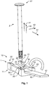
Fig. 1 shows a schematic perspective view of a first embodiment of a component group prior to the insertion of an armature; -
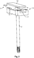
Fig. 2 shows a schematic perspective view of the component group fromFig. 1 with the armature inserted; -
Fig. 3 shows a schematic perspective view of the component group fromFig. 1 during attachment of a switching bridge carrier; -
Fig. 4 shows a schematic perspective view of the component group fromFig. 1 with the switching bridge carrier attached; -
Fig. 5 shows a schematic, partly sectioned perspective view of a relay with a component group according toFig. 1 ; -
Fig. 6 shows a schematic, partly sectioned perspective view of a relay with a separation component according toFig. 1 ; -
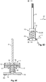
Figs. 7A to 7E show various schematic views of the component group according toFig. 1 ; -
Figs. 8A to 8E show various schematic views of a further embodiment of a component group; -
Fig. 9 shows a schematic perspective view of the further embodiment fromFigures 8A to 8E . -
Figures 1 to 7E show a first embodiment of acomponent group 1 for arelay 100. Thecomponent group 1 serves to electrically insulate anarmature 2 from a switchingbridge 18. The switchingbridge 18 consists of a conductive material and is used to close a load circuit. For this purpose, the switchingbridge 18 has twocontact sites 80 which can come into contact withmating contact sites 81. - The
armature 2 is operatively connected to anelectromagnet 50 of a control circuit and is moved by theelectromagnet 50 in one switchingdirection 40, which thus represents one direction ofmovement 41 of the armature, as a result of different currents flowing into theelectromagnet 50. - In some systems up to now, the switching
bridge 18 and thearmature 2 are connected to one another in a conductive manner. This is disadvantageous, since high-frequency interferences, for example, can be transmitted from the load circuit into the control circuit or vice versa. - In the
present component group 1, there is aseparation component 10 which serves to electrically insulate and thus galvanically separate thearmature 2 from the switchingbridge 18 and a switchingbridge carrier 8. - The
separation component 10 consists of an electrically insulating material, such as a plastic, for example. Areceptacle 15 for thearmature 2 is present on a receivingsection 11. In the example shown, thereceptacle 15 is anaperture 16, into which thearmature 2 can be inserted by being plugged through against the direction ofmovement 40. Theaperture 16 has arecess 17 which, with a head 27 of thearmature 2, generates a form-fit against the direction ofmovement 40. - After the
armature 2 has been fully inserted, acover 12 can be brought over the head 27 and can thus achieve an almost full insulation of thearmature 2 in the region of the head 27. - In the embodiment shown, the receiving
section 11 and thecover 12 are two separate elements, so that these elements can have different materials and thus different properties. In a configuration which is not shown, the receivingsections cover 12 on the receivingsection 11 can be folded open in a simple manner. - After the attachment of the
cover 12, as shown inFig. 2 , the switchingbridge carrier 8 is brought into connection with theseparation component 10, in particular with the receivingsection 11. For this purpose, the receivingsection 11 and the switchingbridge carrier 8 respectively haveconnection elements connection elements connection elements 30 of the switchingbridge carrier 8, which are configured as press-inelements 32, are pressed into theconnection elements 20 of the receivingsection 11, which are configured as press-inapertures 22. In order to obtain a retaining effect, theconnection elements 30 of the switchingbridge carrier 8 haveundercuts 33 and thus form amushroom structure 34. After the plugging-together has been carried out, twoconnection elements - The
cover 12 is retained on the receivingsection 11 by the switchingbridge carrier 8. In an alternative configuration, another type of connection can be present between thecover 12 and the receivingsection 11. For example, thecover 12 can be retained on the receivingsection 11 in a form-fitting manner in or against the direction of movement. - In order to obtain a compact configuration in the direction of
movement 40, the receivingsection 11 and thecover 12 are configured asflat bodies 90 extending transverse to the direction ofmovement 41, in a firsttransverse direction 42 and in a secondtransverse direction 47. -
Figures 5 and6 show arelay 100 with aseparation component 10 in an open or closed state. In addition, thecover 12 is removed inFig. 5 to make possible a view of thereceptacle 17 and thearmature 2. Here, therelay 100 also comprises, in particular, ahousing 110. - The
aperture 16 extends in a direction away from the switchingbridge carrier 8. In an alternative configuration which is not shown, theaperture 16 orreceptacle 15 could be open towards a firsttransverse direction 42 or secondtransverse direction 47, so that thearmature 2 can be inserted laterally, i.e. transverse to the direction ofmovement 41. - Furthermore, in the
relay 100 there is aspring 60 which biases the switchingbridge 18 in the direction ofmovement 41. The switchingbridge 18 haslateral protrusions 71, which cooperate withapertures 72 on the switchingbridge carrier 8 and as a result form aguide 70. To limit the movement, there is astop 74 on the switchingbridge carrier 8 which cooperates with aprotrusion 71. -
Figures 8A to 9 show a second embodiment of acomponent group 10. In contrast to the configuration according toFigures 1 to 7E , the switchingbridge carrier 8 is attached here viaconnection elements fit elements connection elements fit elements movement 41. -
- 1
- component group
- 2
- armature
- 8
- switching bridge carrier
- 10
- separation component
- 11
- receiving section
- 12
- cover
- 15
- receptacle
- 16
- aperture
- 17
- recess
- 18
- switching bridge
- 20
- connection element
- 21
- form-fit element
- 22
- press-in apertures
- 27
- head
- 30
- connection element
- 31
- form-fit element
- 32
- press-in elements
- 33
- undercut
- 34
- mushroom structure
- 38
- film hinge
- 40
- switching direction
- 41
- direction of movement
- 42
- first transverse direction
- 44
- spatial direction
- 47
- second transverse direction
- 50
- electromagnet
- 60
- spring
- 70
- guide
- 71
- protrusion
- 72
- aperture
- 74
- stop
- 80
- contact site
- 81
- mating contact site
- 90
- flat body
- 100
- relay
- 110
- housing
Claims (15)
- A component group (1) for galvanically separating an armature (2) and a switching bridge (18) of a relay (100), the switching bridge (18) being arranged on a switching bridge carrier (8), with a separation component (10) made from an electrically insulating substance, wherein the separation component (10) has a receptacle (15) for inserting the armature (2) and connection elements (20) for plugging together with the switching bridge carrier (8).
- The component group (1) according to claim 1, wherein the separation component (10) has an aperture (16) for plugging the armature (2) through and a cover (12) for the aperture.
- The component group (1) according to claim 1 or 2, wherein the cover (12) is retained in a form-fitting manner at least in one spatial direction on a receiving section (11), on which the receptacle (15) is arranged.
- The component group (1) according to any one of claims 1 to 3, wherein the cover (12) and the receiving section (11) are configured integrally with one another.
- The component group (1) according to any one of claims 1 to 4, wherein the cover (12) can be folded in over the receptacle (15).
- The component group (1) according to any one of claims 1 to 5, wherein the cover (12) is attached to the rest of the separation component (10) via a film hinge.
- The component group (1) according to any one of claims 1 to 6, wherein the connection elements (20) comprise form-fit elements (21).
- The component group (1) according to any one of claims 1 to 7, wherein the connection elements (20) are configured for connection by means of ultrasonic welding.
- The component group (1) according to any one of claims 1 to 8, wherein the connection elements (20) comprise press-in apertures (21).
- The component group (1) according to any one of claims 1 to 9, wherein the receiving section (11) and/or the cover (12) are configured as flat bodies (90).
- The component group (1) according to any one of claims 1 to 10, wherein the component group (1) comprises the switching bridge carrier (8).
- The component group (1) according to any one of claims 1 to 11, wherein the cover (12) is retained by the switching bridge carrier (8).
- The component group (1) according to any one of claims 1 to 12, wherein the switching bridge carrier (8) comprises complementary connection elements (30).
- The component group (1) according to any one of claims 1 to 13, wherein the component group (1) comprises the armature (2).
- A relay (100) comprising a component group (1) according to any one of claims 1 to 14.
Applications Claiming Priority (1)
| Application Number | Priority Date | Filing Date | Title |
|---|---|---|---|
| DE102018204014.1A DE102018204014A1 (en) | 2018-03-16 | 2018-03-16 | Assembly for the galvanic isolation of an armature and a switching bridge of a relay arranged on a switching bridge carrier, and relays |
Publications (2)
| Publication Number | Publication Date |
|---|---|
| EP3540754A1 true EP3540754A1 (en) | 2019-09-18 |
| EP3540754B1 EP3540754B1 (en) | 2021-03-03 |
Family
ID=65818338
Family Applications (1)
| Application Number | Title | Priority Date | Filing Date |
|---|---|---|---|
| EP19163456.7A Active EP3540754B1 (en) | 2018-03-16 | 2019-03-18 | Component group for galvanically separating an armature and a switching bridge of a relay, the switching bridge being arranged on a switching bridge carrier, and relay |
Country Status (6)
| Country | Link |
|---|---|
| US (1) | US11139132B2 (en) |
| EP (1) | EP3540754B1 (en) |
| JP (1) | JP2019160797A (en) |
| KR (1) | KR20190109304A (en) |
| CN (1) | CN110277280A (en) |
| DE (1) | DE102018204014A1 (en) |
Families Citing this family (3)
| Publication number | Priority date | Publication date | Assignee | Title |
|---|---|---|---|---|
| KR102531476B1 (en) * | 2020-09-25 | 2023-05-11 | 엘에스일렉트릭(주) | Moving contactor part and direct current relay include the same |
| DE102021128179A1 (en) * | 2021-10-28 | 2023-05-04 | Te Connectivity Germany Gmbh | Switching contact assembly for an electrical switching element and electrical switching element |
| DE102023111832A1 (en) * | 2023-05-05 | 2024-11-07 | Te Connectivity Solutions Gmbh | Contact bridge arrangement for a relay or contactor |
Citations (2)
| Publication number | Priority date | Publication date | Assignee | Title |
|---|---|---|---|---|
| BE419467A (en) * | ||||
| US20160300676A1 (en) * | 2015-04-13 | 2016-10-13 | Panasonic Intellectual Property Management Co., Ltd. | Contactor and electromagnetic relay |
Family Cites Families (2)
| Publication number | Priority date | Publication date | Assignee | Title |
|---|---|---|---|---|
| US6417749B1 (en) * | 1998-09-30 | 2002-07-09 | Rockwell Automation Technologies, Inc. | Electric contactor housing |
| EP2838103B1 (en) * | 2012-04-09 | 2016-05-18 | Panasonic Intellectual Property Management Co., Ltd. | Contact device spring load adjustment structure and contact device spring load adjustment method |
-
2018
- 2018-03-16 DE DE102018204014.1A patent/DE102018204014A1/en not_active Withdrawn
-
2019
- 2019-03-13 JP JP2019045309A patent/JP2019160797A/en active Pending
- 2019-03-15 US US16/354,951 patent/US11139132B2/en not_active Expired - Fee Related
- 2019-03-15 KR KR1020190029971A patent/KR20190109304A/en not_active Ceased
- 2019-03-18 EP EP19163456.7A patent/EP3540754B1/en active Active
- 2019-03-18 CN CN201910202021.4A patent/CN110277280A/en active Pending
Patent Citations (2)
| Publication number | Priority date | Publication date | Assignee | Title |
|---|---|---|---|---|
| BE419467A (en) * | ||||
| US20160300676A1 (en) * | 2015-04-13 | 2016-10-13 | Panasonic Intellectual Property Management Co., Ltd. | Contactor and electromagnetic relay |
Also Published As
| Publication number | Publication date |
|---|---|
| US20190287747A1 (en) | 2019-09-19 |
| US11139132B2 (en) | 2021-10-05 |
| EP3540754B1 (en) | 2021-03-03 |
| CN110277280A (en) | 2019-09-24 |
| DE102018204014A1 (en) | 2019-09-19 |
| KR20190109304A (en) | 2019-09-25 |
| JP2019160797A (en) | 2019-09-19 |
Similar Documents
| Publication | Publication Date | Title |
|---|---|---|
| US10673159B2 (en) | Grounded electrical connector | |
| US10236612B2 (en) | Flat contact socket | |
| EP3540754B1 (en) | Component group for galvanically separating an armature and a switching bridge of a relay, the switching bridge being arranged on a switching bridge carrier, and relay | |
| CN111771306B (en) | Female terminal | |
| EP3376598A1 (en) | A contact carrier, electrical contact unit and a method of producing a ready-made cable | |
| JP2016510940A (en) | Right angle header assembly | |
| US20130252474A1 (en) | Electrical connection system | |
| US20190109395A1 (en) | Electrical terminal | |
| JP2013513922A (en) | Electrical contacts for plug-in connections | |
| JP7093889B2 (en) | Electromechanical switch with stable engagement between contacts | |
| KR20170079582A (en) | Power distributing apparatus and assembling method | |
| US11600938B2 (en) | Bridge element for establishing an electrical connection, and arrangement | |
| KR20210129964A (en) | High power female blade terminal connection structure | |
| KR102585070B1 (en) | Plug and method of attaching a vibration protection to a plug | |
| US10177489B1 (en) | Connector device | |
| CN113196576A (en) | Wire harness member | |
| KR102202562B1 (en) | connector | |
| WO2019167599A1 (en) | Female terminal | |
| KR20250157239A (en) | Movable carrier structure for electrical device | |
| TW202005192A (en) | Contact device with a spring fork | |
| US11417971B2 (en) | Assembly element for an actuator | |
| CN110494273B (en) | Method for connecting three components and connectable system for carrying out the method | |
| JP7152251B2 (en) | Electrical wiring block assembly, electrical connection box and wire harness | |
| CN102376467B (en) | Contact element and the system including contact element and counter element | |
| KR101617752B1 (en) | electrode structure for vehicle electronic apparatus |
Legal Events
| Date | Code | Title | Description |
|---|---|---|---|
| PUAI | Public reference made under article 153(3) epc to a published international application that has entered the european phase |
Free format text: ORIGINAL CODE: 0009012 |
|
| STAA | Information on the status of an ep patent application or granted ep patent |
Free format text: STATUS: THE APPLICATION HAS BEEN PUBLISHED |
|
| AK | Designated contracting states |
Kind code of ref document: A1 Designated state(s): AL AT BE BG CH CY CZ DE DK EE ES FI FR GB GR HR HU IE IS IT LI LT LU LV MC MK MT NL NO PL PT RO RS SE SI SK SM TR |
|
| AX | Request for extension of the european patent |
Extension state: BA ME |
|
| STAA | Information on the status of an ep patent application or granted ep patent |
Free format text: STATUS: REQUEST FOR EXAMINATION WAS MADE |
|
| STAA | Information on the status of an ep patent application or granted ep patent |
Free format text: STATUS: EXAMINATION IS IN PROGRESS |
|
| 17P | Request for examination filed |
Effective date: 20200312 |
|
| RBV | Designated contracting states (corrected) |
Designated state(s): AL AT BE BG CH CY CZ DE DK EE ES FI FR GB GR HR HU IE IS IT LI LT LU LV MC MK MT NL NO PL PT RO RS SE SI SK SM TR |
|
| 17Q | First examination report despatched |
Effective date: 20200416 |
|
| GRAP | Despatch of communication of intention to grant a patent |
Free format text: ORIGINAL CODE: EPIDOSNIGR1 |
|
| STAA | Information on the status of an ep patent application or granted ep patent |
Free format text: STATUS: GRANT OF PATENT IS INTENDED |
|
| INTG | Intention to grant announced |
Effective date: 20201002 |
|
| GRAS | Grant fee paid |
Free format text: ORIGINAL CODE: EPIDOSNIGR3 |
|
| GRAA | (expected) grant |
Free format text: ORIGINAL CODE: 0009210 |
|
| STAA | Information on the status of an ep patent application or granted ep patent |
Free format text: STATUS: THE PATENT HAS BEEN GRANTED |
|
| AK | Designated contracting states |
Kind code of ref document: B1 Designated state(s): AL AT BE BG CH CY CZ DE DK EE ES FI FR GB GR HR HU IE IS IT LI LT LU LV MC MK MT NL NO PL PT RO RS SE SI SK SM TR |
|
| REG | Reference to a national code |
Ref country code: GB Ref legal event code: FG4D |
|
| REG | Reference to a national code |
Ref country code: CH Ref legal event code: EP Ref country code: AT Ref legal event code: REF Ref document number: 1368121 Country of ref document: AT Kind code of ref document: T Effective date: 20210315 |
|
| REG | Reference to a national code |
Ref country code: DE Ref legal event code: R096 Ref document number: 602019002851 Country of ref document: DE |
|
| REG | Reference to a national code |
Ref country code: IE Ref legal event code: FG4D |
|
| REG | Reference to a national code |
Ref country code: LT Ref legal event code: MG9D |
|
| PG25 | Lapsed in a contracting state [announced via postgrant information from national office to epo] |
Ref country code: BG Free format text: LAPSE BECAUSE OF FAILURE TO SUBMIT A TRANSLATION OF THE DESCRIPTION OR TO PAY THE FEE WITHIN THE PRESCRIBED TIME-LIMIT Effective date: 20210603 Ref country code: HR Free format text: LAPSE BECAUSE OF FAILURE TO SUBMIT A TRANSLATION OF THE DESCRIPTION OR TO PAY THE FEE WITHIN THE PRESCRIBED TIME-LIMIT Effective date: 20210303 Ref country code: GR Free format text: LAPSE BECAUSE OF FAILURE TO SUBMIT A TRANSLATION OF THE DESCRIPTION OR TO PAY THE FEE WITHIN THE PRESCRIBED TIME-LIMIT Effective date: 20210604 Ref country code: FI Free format text: LAPSE BECAUSE OF FAILURE TO SUBMIT A TRANSLATION OF THE DESCRIPTION OR TO PAY THE FEE WITHIN THE PRESCRIBED TIME-LIMIT Effective date: 20210303 Ref country code: NO Free format text: LAPSE BECAUSE OF FAILURE TO SUBMIT A TRANSLATION OF THE DESCRIPTION OR TO PAY THE FEE WITHIN THE PRESCRIBED TIME-LIMIT Effective date: 20210603 Ref country code: LT Free format text: LAPSE BECAUSE OF FAILURE TO SUBMIT A TRANSLATION OF THE DESCRIPTION OR TO PAY THE FEE WITHIN THE PRESCRIBED TIME-LIMIT Effective date: 20210303 |
|
| REG | Reference to a national code |
Ref country code: NL Ref legal event code: MP Effective date: 20210303 |
|
| REG | Reference to a national code |
Ref country code: AT Ref legal event code: MK05 Ref document number: 1368121 Country of ref document: AT Kind code of ref document: T Effective date: 20210303 |
|
| PG25 | Lapsed in a contracting state [announced via postgrant information from national office to epo] |
Ref country code: RS Free format text: LAPSE BECAUSE OF FAILURE TO SUBMIT A TRANSLATION OF THE DESCRIPTION OR TO PAY THE FEE WITHIN THE PRESCRIBED TIME-LIMIT Effective date: 20210303 Ref country code: PL Free format text: LAPSE BECAUSE OF FAILURE TO SUBMIT A TRANSLATION OF THE DESCRIPTION OR TO PAY THE FEE WITHIN THE PRESCRIBED TIME-LIMIT Effective date: 20210303 Ref country code: LV Free format text: LAPSE BECAUSE OF FAILURE TO SUBMIT A TRANSLATION OF THE DESCRIPTION OR TO PAY THE FEE WITHIN THE PRESCRIBED TIME-LIMIT Effective date: 20210303 Ref country code: SE Free format text: LAPSE BECAUSE OF FAILURE TO SUBMIT A TRANSLATION OF THE DESCRIPTION OR TO PAY THE FEE WITHIN THE PRESCRIBED TIME-LIMIT Effective date: 20210303 |
|
| PG25 | Lapsed in a contracting state [announced via postgrant information from national office to epo] |
Ref country code: NL Free format text: LAPSE BECAUSE OF FAILURE TO SUBMIT A TRANSLATION OF THE DESCRIPTION OR TO PAY THE FEE WITHIN THE PRESCRIBED TIME-LIMIT Effective date: 20210303 |
|
| PG25 | Lapsed in a contracting state [announced via postgrant information from national office to epo] |
Ref country code: SM Free format text: LAPSE BECAUSE OF FAILURE TO SUBMIT A TRANSLATION OF THE DESCRIPTION OR TO PAY THE FEE WITHIN THE PRESCRIBED TIME-LIMIT Effective date: 20210303 Ref country code: AT Free format text: LAPSE BECAUSE OF FAILURE TO SUBMIT A TRANSLATION OF THE DESCRIPTION OR TO PAY THE FEE WITHIN THE PRESCRIBED TIME-LIMIT Effective date: 20210303 Ref country code: EE Free format text: LAPSE BECAUSE OF FAILURE TO SUBMIT A TRANSLATION OF THE DESCRIPTION OR TO PAY THE FEE WITHIN THE PRESCRIBED TIME-LIMIT Effective date: 20210303 Ref country code: CZ Free format text: LAPSE BECAUSE OF FAILURE TO SUBMIT A TRANSLATION OF THE DESCRIPTION OR TO PAY THE FEE WITHIN THE PRESCRIBED TIME-LIMIT Effective date: 20210303 |
|
| PG25 | Lapsed in a contracting state [announced via postgrant information from national office to epo] |
Ref country code: PT Free format text: LAPSE BECAUSE OF FAILURE TO SUBMIT A TRANSLATION OF THE DESCRIPTION OR TO PAY THE FEE WITHIN THE PRESCRIBED TIME-LIMIT Effective date: 20210705 Ref country code: RO Free format text: LAPSE BECAUSE OF FAILURE TO SUBMIT A TRANSLATION OF THE DESCRIPTION OR TO PAY THE FEE WITHIN THE PRESCRIBED TIME-LIMIT Effective date: 20210303 Ref country code: SK Free format text: LAPSE BECAUSE OF FAILURE TO SUBMIT A TRANSLATION OF THE DESCRIPTION OR TO PAY THE FEE WITHIN THE PRESCRIBED TIME-LIMIT Effective date: 20210303 Ref country code: IS Free format text: LAPSE BECAUSE OF FAILURE TO SUBMIT A TRANSLATION OF THE DESCRIPTION OR TO PAY THE FEE WITHIN THE PRESCRIBED TIME-LIMIT Effective date: 20210703 |
|
| REG | Reference to a national code |
Ref country code: DE Ref legal event code: R097 Ref document number: 602019002851 Country of ref document: DE |
|
| REG | Reference to a national code |
Ref country code: BE Ref legal event code: MM Effective date: 20210331 |
|
| PLBE | No opposition filed within time limit |
Free format text: ORIGINAL CODE: 0009261 |
|
| STAA | Information on the status of an ep patent application or granted ep patent |
Free format text: STATUS: NO OPPOSITION FILED WITHIN TIME LIMIT |
|
| PG25 | Lapsed in a contracting state [announced via postgrant information from national office to epo] |
Ref country code: ES Free format text: LAPSE BECAUSE OF FAILURE TO SUBMIT A TRANSLATION OF THE DESCRIPTION OR TO PAY THE FEE WITHIN THE PRESCRIBED TIME-LIMIT Effective date: 20210303 Ref country code: MC Free format text: LAPSE BECAUSE OF FAILURE TO SUBMIT A TRANSLATION OF THE DESCRIPTION OR TO PAY THE FEE WITHIN THE PRESCRIBED TIME-LIMIT Effective date: 20210303 Ref country code: AL Free format text: LAPSE BECAUSE OF FAILURE TO SUBMIT A TRANSLATION OF THE DESCRIPTION OR TO PAY THE FEE WITHIN THE PRESCRIBED TIME-LIMIT Effective date: 20210303 Ref country code: DK Free format text: LAPSE BECAUSE OF FAILURE TO SUBMIT A TRANSLATION OF THE DESCRIPTION OR TO PAY THE FEE WITHIN THE PRESCRIBED TIME-LIMIT Effective date: 20210303 Ref country code: IE Free format text: LAPSE BECAUSE OF NON-PAYMENT OF DUE FEES Effective date: 20210318 Ref country code: LU Free format text: LAPSE BECAUSE OF NON-PAYMENT OF DUE FEES Effective date: 20210318 |
|
| 26N | No opposition filed |
Effective date: 20211206 |
|
| PG25 | Lapsed in a contracting state [announced via postgrant information from national office to epo] |
Ref country code: SI Free format text: LAPSE BECAUSE OF FAILURE TO SUBMIT A TRANSLATION OF THE DESCRIPTION OR TO PAY THE FEE WITHIN THE PRESCRIBED TIME-LIMIT Effective date: 20210303 |
|
| PG25 | Lapsed in a contracting state [announced via postgrant information from national office to epo] |
Ref country code: IS Free format text: LAPSE BECAUSE OF FAILURE TO SUBMIT A TRANSLATION OF THE DESCRIPTION OR TO PAY THE FEE WITHIN THE PRESCRIBED TIME-LIMIT Effective date: 20210703 |
|
| PG25 | Lapsed in a contracting state [announced via postgrant information from national office to epo] |
Ref country code: BE Free format text: LAPSE BECAUSE OF NON-PAYMENT OF DUE FEES Effective date: 20210331 |
|
| REG | Reference to a national code |
Ref country code: CH Ref legal event code: PL |
|
| PG25 | Lapsed in a contracting state [announced via postgrant information from national office to epo] |
Ref country code: LI Free format text: LAPSE BECAUSE OF NON-PAYMENT OF DUE FEES Effective date: 20220331 Ref country code: CH Free format text: LAPSE BECAUSE OF NON-PAYMENT OF DUE FEES Effective date: 20220331 |
|
| PG25 | Lapsed in a contracting state [announced via postgrant information from national office to epo] |
Ref country code: CY Free format text: LAPSE BECAUSE OF FAILURE TO SUBMIT A TRANSLATION OF THE DESCRIPTION OR TO PAY THE FEE WITHIN THE PRESCRIBED TIME-LIMIT Effective date: 20210303 |
|
| PG25 | Lapsed in a contracting state [announced via postgrant information from national office to epo] |
Ref country code: HU Free format text: LAPSE BECAUSE OF FAILURE TO SUBMIT A TRANSLATION OF THE DESCRIPTION OR TO PAY THE FEE WITHIN THE PRESCRIBED TIME-LIMIT; INVALID AB INITIO Effective date: 20190318 |
|
| GBPC | Gb: european patent ceased through non-payment of renewal fee |
Effective date: 20230318 |
|
| PG25 | Lapsed in a contracting state [announced via postgrant information from national office to epo] |
Ref country code: GB Free format text: LAPSE BECAUSE OF NON-PAYMENT OF DUE FEES Effective date: 20230318 |
|
| PG25 | Lapsed in a contracting state [announced via postgrant information from national office to epo] |
Ref country code: GB Free format text: LAPSE BECAUSE OF NON-PAYMENT OF DUE FEES Effective date: 20230318 |
|
| PG25 | Lapsed in a contracting state [announced via postgrant information from national office to epo] |
Ref country code: MK Free format text: LAPSE BECAUSE OF FAILURE TO SUBMIT A TRANSLATION OF THE DESCRIPTION OR TO PAY THE FEE WITHIN THE PRESCRIBED TIME-LIMIT Effective date: 20210303 |
|
| PG25 | Lapsed in a contracting state [announced via postgrant information from national office to epo] |
Ref country code: TR Free format text: LAPSE BECAUSE OF FAILURE TO SUBMIT A TRANSLATION OF THE DESCRIPTION OR TO PAY THE FEE WITHIN THE PRESCRIBED TIME-LIMIT Effective date: 20210303 |
|
| PG25 | Lapsed in a contracting state [announced via postgrant information from national office to epo] |
Ref country code: MT Free format text: LAPSE BECAUSE OF FAILURE TO SUBMIT A TRANSLATION OF THE DESCRIPTION OR TO PAY THE FEE WITHIN THE PRESCRIBED TIME-LIMIT Effective date: 20210303 |
|
| PGFP | Annual fee paid to national office [announced via postgrant information from national office to epo] |
Ref country code: FR Payment date: 20251231 Year of fee payment: 8 |
|
| PGFP | Annual fee paid to national office [announced via postgrant information from national office to epo] |
Ref country code: DE Payment date: 20260102 Year of fee payment: 8 |
|
| PGFP | Annual fee paid to national office [announced via postgrant information from national office to epo] |
Ref country code: IT Payment date: 20260220 Year of fee payment: 8 |