EP3540691A1 - Method of segmentation and annotation of images - Google Patents
Method of segmentation and annotation of images Download PDFInfo
- Publication number
- EP3540691A1 EP3540691A1 EP18161642.6A EP18161642A EP3540691A1 EP 3540691 A1 EP3540691 A1 EP 3540691A1 EP 18161642 A EP18161642 A EP 18161642A EP 3540691 A1 EP3540691 A1 EP 3540691A1
- Authority
- EP
- European Patent Office
- Prior art keywords
- image
- roi
- fiduciary
- edge
- proposed
- Prior art date
- Legal status (The legal status is an assumption and is not a legal conclusion. Google has not performed a legal analysis and makes no representation as to the accuracy of the status listed.)
- Granted
Links
Images



Classifications
-
- G—PHYSICS
- G06—COMPUTING OR CALCULATING; COUNTING
- G06T—IMAGE DATA PROCESSING OR GENERATION, IN GENERAL
- G06T7/00—Image analysis
- G06T7/10—Segmentation; Edge detection
- G06T7/11—Region-based segmentation
-
- G—PHYSICS
- G06—COMPUTING OR CALCULATING; COUNTING
- G06F—ELECTRIC DIGITAL DATA PROCESSING
- G06F18/00—Pattern recognition
- G06F18/20—Analysing
- G06F18/23—Clustering techniques
-
- G—PHYSICS
- G06—COMPUTING OR CALCULATING; COUNTING
- G06T—IMAGE DATA PROCESSING OR GENERATION, IN GENERAL
- G06T5/00—Image enhancement or restoration
- G06T5/20—Image enhancement or restoration using local operators
-
- G—PHYSICS
- G06—COMPUTING OR CALCULATING; COUNTING
- G06T—IMAGE DATA PROCESSING OR GENERATION, IN GENERAL
- G06T5/00—Image enhancement or restoration
- G06T5/70—Denoising; Smoothing
-
- G—PHYSICS
- G06—COMPUTING OR CALCULATING; COUNTING
- G06T—IMAGE DATA PROCESSING OR GENERATION, IN GENERAL
- G06T5/00—Image enhancement or restoration
- G06T5/73—Deblurring; Sharpening
-
- G—PHYSICS
- G06—COMPUTING OR CALCULATING; COUNTING
- G06T—IMAGE DATA PROCESSING OR GENERATION, IN GENERAL
- G06T7/00—Image analysis
- G06T7/10—Segmentation; Edge detection
- G06T7/12—Edge-based segmentation
-
- G—PHYSICS
- G06—COMPUTING OR CALCULATING; COUNTING
- G06T—IMAGE DATA PROCESSING OR GENERATION, IN GENERAL
- G06T7/00—Image analysis
- G06T7/10—Segmentation; Edge detection
- G06T7/194—Segmentation; Edge detection involving foreground-background segmentation
-
- G—PHYSICS
- G06—COMPUTING OR CALCULATING; COUNTING
- G06V—IMAGE OR VIDEO RECOGNITION OR UNDERSTANDING
- G06V10/00—Arrangements for image or video recognition or understanding
- G06V10/20—Image preprocessing
- G06V10/25—Determination of region of interest [ROI] or a volume of interest [VOI]
-
- G—PHYSICS
- G06—COMPUTING OR CALCULATING; COUNTING
- G06V—IMAGE OR VIDEO RECOGNITION OR UNDERSTANDING
- G06V10/00—Arrangements for image or video recognition or understanding
- G06V10/20—Image preprocessing
- G06V10/30—Noise filtering
-
- G—PHYSICS
- G06—COMPUTING OR CALCULATING; COUNTING
- G06T—IMAGE DATA PROCESSING OR GENERATION, IN GENERAL
- G06T2207/00—Indexing scheme for image analysis or image enhancement
- G06T2207/20—Special algorithmic details
- G06T2207/20016—Hierarchical, coarse-to-fine, multiscale or multiresolution image processing; Pyramid transform
-
- G—PHYSICS
- G06—COMPUTING OR CALCULATING; COUNTING
- G06T—IMAGE DATA PROCESSING OR GENERATION, IN GENERAL
- G06T2207/00—Indexing scheme for image analysis or image enhancement
- G06T2207/20—Special algorithmic details
- G06T2207/20024—Filtering details
- G06T2207/20028—Bilateral filtering
-
- G—PHYSICS
- G06—COMPUTING OR CALCULATING; COUNTING
- G06T—IMAGE DATA PROCESSING OR GENERATION, IN GENERAL
- G06T2207/00—Indexing scheme for image analysis or image enhancement
- G06T2207/20—Special algorithmic details
- G06T2207/20081—Training; Learning
-
- G—PHYSICS
- G06—COMPUTING OR CALCULATING; COUNTING
- G06T—IMAGE DATA PROCESSING OR GENERATION, IN GENERAL
- G06T2207/00—Indexing scheme for image analysis or image enhancement
- G06T2207/20—Special algorithmic details
- G06T2207/20084—Artificial neural networks [ANN]
-
- G—PHYSICS
- G06—COMPUTING OR CALCULATING; COUNTING
- G06T—IMAGE DATA PROCESSING OR GENERATION, IN GENERAL
- G06T2207/00—Indexing scheme for image analysis or image enhancement
- G06T2207/20—Special algorithmic details
- G06T2207/20092—Interactive image processing based on input by user
- G06T2207/20104—Interactive definition of region of interest [ROI]
-
- G—PHYSICS
- G06—COMPUTING OR CALCULATING; COUNTING
- G06T—IMAGE DATA PROCESSING OR GENERATION, IN GENERAL
- G06T2207/00—Indexing scheme for image analysis or image enhancement
- G06T2207/20—Special algorithmic details
- G06T2207/20172—Image enhancement details
- G06T2207/20192—Edge enhancement; Edge preservation
-
- G—PHYSICS
- G06—COMPUTING OR CALCULATING; COUNTING
- G06T—IMAGE DATA PROCESSING OR GENERATION, IN GENERAL
- G06T2207/00—Indexing scheme for image analysis or image enhancement
- G06T2207/30—Subject of image; Context of image processing
- G06T2207/30248—Vehicle exterior or interior
- G06T2207/30252—Vehicle exterior; Vicinity of vehicle
Definitions
- the present invention relates to a method for annotation and segmentation of images.
- the present invention relates to semi-automated annotation and segmentation of images suitable to be used for training of vehicle systems.
- the automated driving (AD) and advanced driver-assistance systems (ADAS) required for providing the desired functionalities include technologies such as such as RADAR, LIDAR, ultrasound and image based systems.
- Manually annotated data i.e. images where a human operator has manually defined the various objects on interest can be considered to be reliable and is therefore often used.
- manually annotated data is expensive in terms of the time and expertise required to segment and annotate the regions of interest.
- manually annotated data is prone to demonstrate inter-observer variabilities where the annotations provided by two different operators may vary significantly, which in turn rises the need for a quality control mechanism such as an independent review process, thereby making the annotation process even more demanding.
- a method for image segmentation and annotation comprising: providing an image; reducing the image size and smoothen the image to perform low-pass filtering of the image; restoring the image size; performing pixel level clustering of the image; performing spatial clustering of the image; selecting one or more clusters corresponding to a region of interest (ROI) based on a predetermined image mask, wherein the predetermined image mask has a known location in relation to the ROI; defining the selected one or more clusters as a proposed ROI; and determining if the proposed ROI sufficiently corresponds to an actual ROI.
- ROI region of interest
- the images may be images acquired by a camera arranged in a vehicle or on the outside of the vehicle, where the image illustrates the vehicle surroundings.
- the image may thus comprise a variety of objects such as road, sky, trees, buildings, other vehicles, etc.
- the images are suitable for use as training images for various vehicle systems comprising cameras and object recognition to provide guidance for the vehicle.
- the images can be captured by the same vehicle system for which they are to be used for training after annotation.
- a plurality of images may be stored in a database prior to performing the described method of image segmentation and annotation.
- Image size reduction and smoothening i.e. low-pass filtering of the image, is performed to highlight larger substantially uniform areas in the image which may correspond to a potential ROI, while reducing the visibility of smaller areas and objects which may otherwise interfere with the ROI detection.
- Reducing the image size typically means shrinking an image of size, for example from 512x512 pixels to 256x256 pixels.
- pixel level clustering is performed where pixels having similar properties with respect to one or more pixel parameters are grouped together and defined as clusters.
- a subset of clusters of the image is selected based on a predetermined image mask.
- the predetermined image mask is applied to the image and it is assumed that the predetermined image mask has a known location in relation to the sought ROI type. Taking the example where the ROI is the sky, it can be a reasonable first assumption that the upper portion of the image consists of sky. Thereby, the predetermined image mask can correspond to a top region of the image. The sky would then be located primarily below the predetermined image mask in the image.
- a first proposal for an actual ROI can be defined. Once an approximate location of the ROI is determined, a proposal ROI can be defined by selecting the clusters appearing to encompass the sought object or region.
- the proposed ROI sufficiently corresponds to an actual ROI. Since the described method relates to semi-automated annotation of images, it is an operator (i.e. a manual annotator) which makes the final call determining if the proposed ROI is acceptable. A measure of the acceptability of the final ROI can then be determined in terms of the area overlap (IoU: intersection over union) between multiple manual annotators having annotated the same image. The annotator may also manually adjust the ROI with the help of automation tools which will be described in further detail in the following. Any such manual annotations can then be fed into deep learning models that can learn to better predict the ROIs for new incoming test images to be annotated.
- IOU intersection over union
- a semi-automated system that provides an accurate initial ROI-proposal which may be followed by a minimal number of touch-points/corrective pixels for manual correction (pixel deletion or addition).
- the described method can significantly enhance the throughput for annotation systems and greatly reduce the annotation costs for AD/ADAS systems.
- the method may further comprise applying pixel level correction to the proposed ROI by adding or removing selected pixels from the proposed ROI.
- Pixel level corrections are made to the proposed ROI based on image-related features such as pixel color, texture, neighborhood information etc., where pixels having selected properties may be added to or removed from the ROI.
- the method may further comprise performing region level correction to the ROI by adding or removing selected clusters from the proposed ROI. Thereby, if a user points at a particular pixel location, all pixels belonging to the same cluster get selected for correction, i.e. for addition to or removal from the ROI.
- the method may further comprise performing edge correction by modifying the edges of the proposed ROI.
- the edges of the proposed ROI can thus be moved and/or the shape of edges can be changed to provide a better match between the proposed ROI and an actual ROI as visually identified by the operator.
- the edge correction may further comprise defining fiduciary edges of the ROI by connecting a plurality of fiduciary points of the image.
- a fiduciary edge can be defined by a plurality of fiduciary points in the image, where a fiduciary point is a pixel or group of pixels that serve as reference points or markers. If two or more fiduciary points are joined together, they represent a fiduciary edge.
- a fiduciary edge is constructed across pixels/edges that are automatically detected, and hence this process reduces the number of manual touch points needed for corrections.
- the automatically detected fiduciary points can thus be used for quality control while segmenting large surfaces, e.g. drivable surfaces.
- the goal of the proposed method is to minimize manual intervention during the annotation process for large-sized objects/surfaces/regions of interest.
- the resulting automatic proposals for region of interest generate baseline (repeatable, reproducible) outcomes.
- fiduciary points may be identified by filtering.
- image filters such as a Sobel filter, a Canny edge detection method and/or a high-pass filter, significant fiduciary points can be automatically highlighted in the image to further simplify edge detection and edge correction.
- the operator may select the suitable fiduciary points to join together to for a fiduciary edge.
- defining a fiduciary edge may comprise fitting a polyline to the ROI, wherein the polyline is based on a plurality of fiduciary points.
- a polyline is a continuous line composed of one or more line segments where each line segment here is a straight line between two fiduciary points.
- performing edge correction may comprise selecting a fiduciary edge, maintaining pixels from the ROI on a selected side of the fiduciary edge and removing pixels from the ROI on the opposite side of the fiduciary edge.
- smoothing may be performed by applying a bilateral filter to the image.
- the bilateral filter preserves sharp edges in the image but blurs the larger regions. Accordingly, the smoothing operation removes subtle distinctions in pixel values in a particular region. This increases the probability of selecting a larger proposed ROI since the visibility of minor differences in the image is reduced.
- pixel level clustering may be performed using a super-pixel segmentation method or a self-organizing map method.
- spatial clustering may be performed using a Density-based spatial clustering of applications with noise, DBSCAN-, method.
- Many clustering algorithms require the number of final clusters as an input (e.g. K-means).
- density-based clustering algorithms such as DBSCAN are useful since they do not require the number of final clusters as an input.
- any distance-based thresholding methods such as self-organizing maps, SOM for spatial clustering can be used in the described application.
- a computer program comprising program code means for performing the steps of any of the aforementioned embodiments when the program is run on a computer, and a computer readable medium carrying a computer program comprising program code means for performing the above described steps when the program product is run on a computer.
- various embodiments of the method according to the present invention are mainly described with reference to a method for segmentation and annotation of an image where the drivable surface is the region of interest (ROI).
- the described method can of course be used also for detection and annotation of other types of regions and objects.
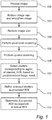
- Fig. 1 is a flow chart outlining the general steps of a method according to an embodiment of the invention. The method of Fig. 1 will be described with further reference to Figs. 2A-G schematically illustrating selected steps of the method.
- an image 200 is provided 100 as illustrated in Fig. 2A .
- the image 200 preferably represents an image 200 which is captured by a camera in a vehicle system to be trained with the resulting annotated image.
- the image 200 is captured by a front facing camera arranged in or near the front window of the vehicle, capturing the road ahead. It is further assumed that the image 200 contains a region of interest to be identified by the described method, i.e. a region which will be relevant to detect and identify in one or more vehicle systems.
- the image size is reduced and the image is smoothened 102, for example by applying a bilateral filter to the image.
- low-pass filtering on the image is performed where the resulting smoothened image 202 is illustrated in Fig. 2B .
- Reducing the image size comprises reducing the number of pixels in the image, for example by a factor four.
- pixels of the drivable surface road
- small objects such as lane markings disappear, thereby allowing for easier detection of the drivable surface ROI as the initial proposal.
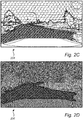
- the image size is restored 104 and pixel level clustering is performed 106 on the image using a super-pixel or self - organizing maps method where pixel intensity values are clustered in 3-dimensions, resulting in the image 204 illustrated in Fig. 2C .
- spatial clustering of the image i.e. spatial combination of pixel-level clusters
- the clusters represented by cluster centers
- a spatial density-based spatial clustering method such as spdbscan (Super-pixel density-based spatial clustering of applications with noise)
- spdbscan Super-pixel density-based spatial clustering of applications with noise
- one or more clusters corresponding to a region of interest 208 are automatically selected 110 based on a predetermined image mask 210, wherein the predetermined image mask 210 has a known location in relation to the ROI.
- the predetermined image mask 210 enables identification of the large ROI initial proposal region 208 among all the clusters retained in the image 206 of Fig. 2D .
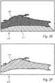
- the resulting selected clusters 208 are illustrated in the image 212 of Fig. 2E .
- the selected clusters 208 are further defined 112 as a proposed ROI 214 illustrated by the image 216 in Fig. 2F .
- the proposed ROI 214 is thus a fully automated initial proposal of the ROI 216.
- the drivable surface would be intersecting with the hood of the car, hence the hood of the car is here used as the prior mask 210.
- a prior mask corresponding to the top region of the image could be selected to identify the ROI.
- any prior information regarding the relative position of the object/ROI that will help separate the ROI proposal from the image can be applied as a prior mask.
- the ROI proposal image 216 is in practice a binary image, where the foreground is marked by white regions (pixel value 1) and background regions by black regions (pixel value 0). Thus, the ROI proposal region 214 that is selected is defined as the foreground and all remaining pixel regions are defined as the background.
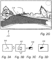
- the proposed ROI 214 it is determined 114 if the proposed ROI 214 sufficiently corresponds to an actual ROI. This determination is here performed by the operator by means of a visual comparison of the proposed ROI 214 with the original image where the proposed ROI 214 can be shown in the original image as illustrated by the image 218 in Fig. 2G .
- an operator i.e. a manual annotator
- acceptability of the final ROI can for example be measured in terms of the area overlap (IoU: intersection over union) between multiple manual annotators.
- the annotation process is completed and a new image can be processed.
- Fig. 2G there are certain regions of the proposed ROI 214 which do not belong to a drivable road surface. Accordingly, further adjustment of the proposed ROI 214 may be required to achieve a sufficient correspondence between the proposed ROI 214 and the actual ROI.
- the required adjustments can be achieved by performing manual pixel-level corrections using one or more of the adjustment tools described in the following.
- the proposed ROI 214 can for example be adjusted by adding or removing selected pixels from the proposed ROI 214 or by adding or removing selected clusters from the proposed ROI 214.
- Cluster based correction can be performed using the image 204 of Fig. 2C where clusters can be manually selected for addition to or removal from the proposed ROI 214.
- the proposed ROI 214 can be adjusted by performing edge correction modifying the edges of the proposed ROI 214.
- a method of edge correction is illustrated by Fig. 3A-D and the general steps are outlined in the flow chart of Fig. 4 .
- Fiduciary edges of the ROI may be defined by connecting a plurality of fiduciary points of the image, where the fiduciary points in turn can be automatically identified by filtering using a Sobel filter, a Canny edge detection method, a high-pass filter or any other suitable method.
- the fiduciary points can be joined to represent a fiduciary edge 300, or a group of fiduciary points. Construction of such a fiduciary edge (an edge that contains fiduciary points) reduces errors across manual annotators for locating the road edge, for example, that is useful to mark the edge of the ROI. A fiduciary edge is constructed across pixels/edges that are automatically detected, and hence this process reduces the number of manual touch points needed for corrections.
- Edge detection can be simplified by fitting a polyline joining the fiduciary points to generate the fiduciary edge 300.
- a polyline is defined as a "connected sequence of line segments", which would simplify detection of a fiduciary edge for a tapering road edge or an irregular, i.e. not completely straight, road edge.
- An automatic polyline fit process can be used for fiduciary edge detection, for example when a long road edge is to be detected.
- An operator can then select a number of disconnected automatic fiduciary edges at a time by clicking at the corresponding disconnected points.
- a polyline fill function will then fit a line (i.e. a fiduciary edge) through the disconnected edge points.
- the operator wishes to detect a smaller fiduciary edge, like the top of a car, or a broken lane line, then selection of one fiduciary edge only may be sufficient, which can then be used to fit a polyline to a small fiduciary edge.
- a backend masking approach is implemented. Accordingly, once the fiduciary edge 300 is created (automatically or manually) and selected 400, and the direction 302 for pixel preservation is chosen as illustrated in Fig. 3B , a sub-image 304 is created 402 and a binary sub-image mask 304 is generated 404 having a length and breadth to exactly fit the selected fiduciary edge 300, such that all pixels in the selected direction (here down) originating from the fiduciary edge 300 and ending at the sub-image end are given the value '1' (foreground) and all remaining pixels are given the value '0' (background).
- This binary sub-image mask 304 illustrated in Fig. 3C is then superimposed 406 on the ROI proposal (in the form of a pixel wise AND-operation) to achieve sharp edge-corrected ROI proposals 306 illustrated in Fig. 3D .
- Figs. 5A-B schematically illustrate the described edge correction method used to modify the proposed ROI 214 of the image 218 in Fig. 2G .
- a fiduciary edge 500 corresponding to the road edge is defined based on a plurality of fiduciary points 502a-e. Once the fiduciary edge 500 is defined, the "down" direction is selected, meaning that the pixels above the fiduciary edge 500 are removed from the proposed ROI, and the final proposed ROI 504 after edge correction is illustrated in Fig. 5B
- the proposed ROI selection method is suitable for larger ROIs such as drivable surface, sky and buildings, smaller objects may also be detected using appropriate settings of the annotation method. Also, the described approach is useful when annotating combination, i.e. non-uniform, drivable surfaces, such as road with slush and snow, water and dry patches, potholes, accumulated snow etc.
Landscapes
- Engineering & Computer Science (AREA)
- Theoretical Computer Science (AREA)
- Physics & Mathematics (AREA)
- General Physics & Mathematics (AREA)
- Computer Vision & Pattern Recognition (AREA)
- Data Mining & Analysis (AREA)
- Artificial Intelligence (AREA)
- Life Sciences & Earth Sciences (AREA)
- Multimedia (AREA)
- Bioinformatics & Cheminformatics (AREA)
- Bioinformatics & Computational Biology (AREA)
- Evolutionary Biology (AREA)
- Evolutionary Computation (AREA)
- General Engineering & Computer Science (AREA)
- Image Analysis (AREA)
- Image Processing (AREA)
Abstract
Description
- The present invention relates to a method for annotation and segmentation of images. In particular, the present invention relates to semi-automated annotation and segmentation of images suitable to be used for training of vehicle systems.
- There is an increasing interest in the development and utilization of driver assistance systems in vehicles, such as lane keeping, braking assist, parking assist and adaptive cruise control systems. There are also concerted efforts to develop semi-autonomous and fully autonomous vehicles.
- The automated driving (AD) and advanced driver-assistance systems (ADAS) required for providing the desired functionalities include technologies such as such as RADAR, LIDAR, ultrasound and image based systems.
- For image based systems operating based on real-time object recognition, it is important that the systems are capable of identifying and classifying various objects surrounding the vehicle. Such systems could be relied upon to identify lane markings, road signs, a drivable road surface, other vehicles, etc.
- However, in order to ensure that such image based systems operate correctly, they often need to be trained on real images where the images are annotated to define the various objects and areas of interest for the particular system, such as object detection, lane detection and drivable surface semantic segmentation.
- Manually annotated data, i.e. images where a human operator has manually defined the various objects on interest can be considered to be reliable and is therefore often used. However, there are also problems related to manually annotated data. One issue is that manually annotated data is expensive in terms of the time and expertise required to segment and annotate the regions of interest. Moreover, manually annotated data is prone to demonstrate inter-observer variabilities where the annotations provided by two different operators may vary significantly, which in turn rises the need for a quality control mechanism such as an independent review process, thereby making the annotation process even more demanding.
- Accordingly, there is a need for method and systems for image segmentation and annotation having increased efficiency.
- In view of above-mentioned and other drawbacks of the prior art, it is an object of the present invention to provide a semi-automated method for image segmentation and annotation which simplifies the image annotation process.
- According to a first aspect of the invention, there is provided a method for image segmentation and annotation comprising: providing an image; reducing the image size and smoothen the image to perform low-pass filtering of the image; restoring the image size; performing pixel level clustering of the image; performing spatial clustering of the image; selecting one or more clusters corresponding to a region of interest (ROI) based on a predetermined image mask, wherein the predetermined image mask has a known location in relation to the ROI; defining the selected one or more clusters as a proposed ROI; and determining if the proposed ROI sufficiently corresponds to an actual ROI.
- The images may be images acquired by a camera arranged in a vehicle or on the outside of the vehicle, where the image illustrates the vehicle surroundings. The image may thus comprise a variety of objects such as road, sky, trees, buildings, other vehicles, etc. Thereby the images are suitable for use as training images for various vehicle systems comprising cameras and object recognition to provide guidance for the vehicle. Preferably, the images can be captured by the same vehicle system for which they are to be used for training after annotation. Moreover, a plurality of images may be stored in a database prior to performing the described method of image segmentation and annotation.
- Image size reduction and smoothening, i.e. low-pass filtering of the image, is performed to highlight larger substantially uniform areas in the image which may correspond to a potential ROI, while reducing the visibility of smaller areas and objects which may otherwise interfere with the ROI detection. Reducing the image size typically means shrinking an image of size, for example from 512x512 pixels to 256x256 pixels.
- Next, pixel level clustering is performed where pixels having similar properties with respect to one or more pixel parameters are grouped together and defined as clusters.
- Once the clustering is performed, a subset of clusters of the image is selected based on a predetermined image mask. The predetermined image mask is applied to the image and it is assumed that the predetermined image mask has a known location in relation to the sought ROI type. Taking the example where the ROI is the sky, it can be a reasonable first assumption that the upper portion of the image consists of sky. Thereby, the predetermined image mask can correspond to a top region of the image. The sky would then be located primarily below the predetermined image mask in the image. Thus, by applying a predetermined image mask having a known location in the image in relation to an assumed position of the sought ROI, a first proposal for an actual ROI can be defined. Once an approximate location of the ROI is determined, a proposal ROI can be defined by selecting the clusters appearing to encompass the sought object or region.
- Finally, it is determined if the proposed ROI sufficiently corresponds to an actual ROI. Since the described method relates to semi-automated annotation of images, it is an operator (i.e. a manual annotator) which makes the final call determining if the proposed ROI is acceptable. A measure of the acceptability of the final ROI can then be determined in terms of the area overlap (IoU: intersection over union) between multiple manual annotators having annotated the same image. The annotator may also manually adjust the ROI with the help of automation tools which will be described in further detail in the following. Any such manual annotations can then be fed into deep learning models that can learn to better predict the ROIs for new incoming test images to be annotated.
- By means of the described method, there is provided a semi-automated system that provides an accurate initial ROI-proposal which may be followed by a minimal number of touch-points/corrective pixels for manual correction (pixel deletion or addition). The described method can significantly enhance the throughput for annotation systems and greatly reduce the annotation costs for AD/ADAS systems.
- If the proposed ROI does not sufficiently correspond to an actual ROI, further modification of the ROI is required. Various steps for further refining the ROI area in the image will be described by the following embodiments, where an operator is provided with various tools to use for modifying the ROI.
- According to one embodiment of the invention, the method may further comprise applying pixel level correction to the proposed ROI by adding or removing selected pixels from the proposed ROI. Pixel level corrections are made to the proposed ROI based on image-related features such as pixel color, texture, neighborhood information etc., where pixels having selected properties may be added to or removed from the ROI.
- According to one embodiment of the invention, the method may further comprise performing region level correction to the ROI by adding or removing selected clusters from the proposed ROI. Thereby, if a user points at a particular pixel location, all pixels belonging to the same cluster get selected for correction, i.e. for addition to or removal from the ROI.
- According to one embodiment of the invention, the method may further comprise performing edge correction by modifying the edges of the proposed ROI. The edges of the proposed ROI can thus be moved and/or the shape of edges can be changed to provide a better match between the proposed ROI and an actual ROI as visually identified by the operator.
- According to one embodiment of the invention, the edge correction may further comprise defining fiduciary edges of the ROI by connecting a plurality of fiduciary points of the image. A fiduciary edge can be defined by a plurality of fiduciary points in the image, where a fiduciary point is a pixel or group of pixels that serve as reference points or markers. If two or more fiduciary points are joined together, they represent a fiduciary edge. A fiduciary edge is constructed across pixels/edges that are automatically detected, and hence this process reduces the number of manual touch points needed for corrections.
- The automatically detected fiduciary points can thus be used for quality control while segmenting large surfaces, e.g. drivable surfaces. The goal of the proposed method is to minimize manual intervention during the annotation process for large-sized objects/surfaces/regions of interest. Moreover, the resulting automatic proposals for region of interest generate baseline (repeatable, reproducible) outcomes.
- According to one embodiment of the invention, fiduciary points may be identified by filtering. By applying image filters such as a Sobel filter, a Canny edge detection method and/or a high-pass filter, significant fiduciary points can be automatically highlighted in the image to further simplify edge detection and edge correction. With fiduciary points highlighted in the image, the operator may select the suitable fiduciary points to join together to for a fiduciary edge.
- According to one embodiment of the invention, defining a fiduciary edge may comprise fitting a polyline to the ROI, wherein the polyline is based on a plurality of fiduciary points. A polyline is a continuous line composed of one or more line segments where each line segment here is a straight line between two fiduciary points.
- According to one embodiment of the invention, performing edge correction may comprise selecting a fiduciary edge, maintaining pixels from the ROI on a selected side of the fiduciary edge and removing pixels from the ROI on the opposite side of the fiduciary edge. Thereby, an easily understandable method is provided to the operator for performing the edge correction where the selected side, defined by a direction away from the fiduciary edge, is selected by the operator. It is also possible to reverse the direction such that pixels on the selected side are removed.
- According to one embodiment of the invention, smoothing may be performed by applying a bilateral filter to the image. The bilateral filter preserves sharp edges in the image but blurs the larger regions. Accordingly, the smoothing operation removes subtle distinctions in pixel values in a particular region. This increases the probability of selecting a larger proposed ROI since the visibility of minor differences in the image is reduced.
- According to one embodiment of the invention, pixel level clustering may be performed using a super-pixel segmentation method or a self-organizing map method.
- According to one embodiment of the invention, spatial clustering may be performed using a Density-based spatial clustering of applications with noise, DBSCAN-, method. Many clustering algorithms require the number of final clusters as an input (e.g. K-means). However, while merging clusters, the final number of clusters cannot be known in advance. Hence density-based clustering algorithms such as DBSCAN are useful since they do not require the number of final clusters as an input. Accordingly, any distance-based thresholding methods (such as self-organizing maps, SOM) for spatial clustering can be used in the described application.
- There is also provided a computer program comprising program code means for performing the steps of any of the aforementioned embodiments when the program is run on a computer, and a computer readable medium carrying a computer program comprising program code means for performing the above described steps when the program product is run on a computer.
- Further features of, and advantages with, the present invention will become apparent when studying the appended claims and the following description. The skilled person realize that different features of the present invention may be combined to create embodiments other than those described in the following, without departing from the scope of the present invention.
- These and other aspects of the present invention will now be described in more detail, with reference to the appended drawings showing an example embodiment of the invention, wherein:
-
Fig. 1 is a flow chart outlining the general steps of a method according to an embodiment of the invention; -
Figs. 2A-G schematically illustrate selected steps of a method according to an embodiment of the invention; -
Figs. 3A-D schematically illustrate selected steps of a method according to an embodiment of the invention; -
Fig. 4 is a flow chart outlining steps of a method according to an embodiment of the invention; and -
Figs. 5A-B schematically illustrate selected steps of a method according to an embodiment of the invention. - In the present detailed description, various embodiments of the method according to the present invention are mainly described with reference to a method for segmentation and annotation of an image where the drivable surface is the region of interest (ROI). The described method can of course be used also for detection and annotation of other types of regions and objects.
-
Fig. 1 is a flow chart outlining the general steps of a method according to an embodiment of the invention. The method ofFig. 1 will be described with further reference toFigs. 2A-G schematically illustrating selected steps of the method. - First, an
image 200 is provided 100 as illustrated inFig. 2A . Theimage 200 preferably represents animage 200 which is captured by a camera in a vehicle system to be trained with the resulting annotated image. Here, theimage 200 is captured by a front facing camera arranged in or near the front window of the vehicle, capturing the road ahead. It is further assumed that theimage 200 contains a region of interest to be identified by the described method, i.e. a region which will be relevant to detect and identify in one or more vehicle systems. - Next, the image size is reduced and the image is smoothened 102, for example by applying a bilateral filter to the image. Thereby low-pass filtering on the image is performed where the resulting
smoothened image 202 is illustrated inFig. 2B . Reducing the image size comprises reducing the number of pixels in the image, for example by a factor four. Here it can be noticed that pixels of the drivable surface (road) become very similar to one another and small objects such as lane markings disappear, thereby allowing for easier detection of the drivable surface ROI as the initial proposal. - Following smoothening, the image size is restored 104 and pixel level clustering is performed 106 on the image using a super-pixel or self - organizing maps method where pixel intensity values are clustered in 3-dimensions, resulting in the
image 204 illustrated inFig. 2C . - In the next step, spatial clustering of the image, i.e. spatial combination of pixel-level clusters, is performed 108 where the clusters (represented by cluster centers) are subjected to a spatial density-based spatial clustering method, such as spdbscan (Super-pixel density-based spatial clustering of applications with noise), to combine clusters with nearest cluster centers, resulting in
image 206 illustrated inFig. 2D . When the image is subjected to super-pixel-like clustering, it divides the low pass filtered image into many clusters/sub-regions. - After clustering is completed, one or more clusters corresponding to a region of
interest 208 are automatically selected 110 based on apredetermined image mask 210, wherein thepredetermined image mask 210 has a known location in relation to the ROI. Thepredetermined image mask 210 enables identification of the large ROIinitial proposal region 208 among all the clusters retained in theimage 206 ofFig. 2D . The resulting selectedclusters 208 are illustrated in theimage 212 ofFig. 2E . The selectedclusters 208 are further defined 112 as a proposedROI 214 illustrated by theimage 216 inFig. 2F . The proposedROI 214 is thus a fully automated initial proposal of theROI 216. - For example in the
image 206 ofFig. 2D , the drivable surface would be intersecting with the hood of the car, hence the hood of the car is here used as theprior mask 210. If the intent instead would be to extract the sky as a region of interest, a prior mask corresponding to the top region of the image could be selected to identify the ROI. In principle, any prior information regarding the relative position of the object/ROI that will help separate the ROI proposal from the image can be applied as a prior mask. - The
ROI proposal image 216 is in practice a binary image, where the foreground is marked by white regions (pixel value 1) and background regions by black regions (pixel value 0). Thus, theROI proposal region 214 that is selected is defined as the foreground and all remaining pixel regions are defined as the background. - In the final step, it is determined 114 if the proposed
ROI 214 sufficiently corresponds to an actual ROI. This determination is here performed by the operator by means of a visual comparison of the proposedROI 214 with the original image where the proposedROI 214 can be shown in the original image as illustrated by theimage 218 inFig. 2G . - Since the described method relates to an annotation application, an operator (i.e. a manual annotator) makes the final call of whether the proposed ROI is acceptable or not with the help of the described automation tools. Acceptability of the final ROI can for example be measured in terms of the area overlap (IoU: intersection over union) between multiple manual annotators. These manual annotations will then feed into deep learning models that can then predict the ROIs for new incoming test images.
- If the proposed
ROI 214 is acceptable, the annotation process is completed and a new image can be processed. However, as can be seen inFig. 2G , there are certain regions of the proposedROI 214 which do not belong to a drivable road surface. Accordingly, further adjustment of the proposedROI 214 may be required to achieve a sufficient correspondence between the proposedROI 214 and the actual ROI. The required adjustments can be achieved by performing manual pixel-level corrections using one or more of the adjustment tools described in the following. - The proposed
ROI 214 can for example be adjusted by adding or removing selected pixels from the proposedROI 214 or by adding or removing selected clusters from the proposedROI 214. Cluster based correction can be performed using theimage 204 ofFig. 2C where clusters can be manually selected for addition to or removal from the proposedROI 214. - Moreover, the proposed
ROI 214 can be adjusted by performing edge correction modifying the edges of the proposedROI 214. A method of edge correction is illustrated byFig. 3A-D and the general steps are outlined in the flow chart ofFig. 4 . - First, a
fiduciary edge 300 to correct and a correction direction is selected 400, as illustrated infig. 3A . Fiduciary edges of the ROI may be defined by connecting a plurality of fiduciary points of the image, where the fiduciary points in turn can be automatically identified by filtering using a Sobel filter, a Canny edge detection method, a high-pass filter or any other suitable method. - Once a number of fiduciary points are highlighted in the image, the fiduciary points can be joined to represent a
fiduciary edge 300, or a group of fiduciary points. Construction of such a fiduciary edge (an edge that contains fiduciary points) reduces errors across manual annotators for locating the road edge, for example, that is useful to mark the edge of the ROI. A fiduciary edge is constructed across pixels/edges that are automatically detected, and hence this process reduces the number of manual touch points needed for corrections. - Edge detection can be simplified by fitting a polyline joining the fiduciary points to generate the
fiduciary edge 300. A polyline is defined as a "connected sequence of line segments", which would simplify detection of a fiduciary edge for a tapering road edge or an irregular, i.e. not completely straight, road edge. - An automatic polyline fit process can be used for fiduciary edge detection, for example when a long road edge is to be detected. An operator can then select a number of disconnected automatic fiduciary edges at a time by clicking at the corresponding disconnected points. A polyline fill function will then fit a line (i.e. a fiduciary edge) through the disconnected edge points. However, if the operator wishes to detect a smaller fiduciary edge, like the top of a car, or a broken lane line, then selection of one fiduciary edge only may be sufficient, which can then be used to fit a polyline to a small fiduciary edge.
- If all the fiduciary points corresponding to an edge can be detected by an edge detector, such as a Canny filter, then no more polyline fitting is necessary. However, in images with varying degrees of contrast, light and shadows in various points if the image, a complete edge with all fiduciary points can be difficult to detect, and hence polyline fitting becomes an important tool for defining the edge. However, if a strong, uniformly lit edge is present in the image, all the fiduciary points may be included in a single edge, which would not need any further polyline estimation.
- The construction of such a fiduciary edge reduces errors across manual annotators for locating the road edge, for example, that is useful to mark the edge of an ROI.
- In order to make the edge correction process computationally fast, a backend masking approach is implemented. Accordingly, once the
fiduciary edge 300 is created (automatically or manually) and selected 400, and thedirection 302 for pixel preservation is chosen as illustrated inFig. 3B , a sub-image 304 is created 402 and a binarysub-image mask 304 is generated 404 having a length and breadth to exactly fit the selectedfiduciary edge 300, such that all pixels in the selected direction (here down) originating from thefiduciary edge 300 and ending at the sub-image end are given the value '1' (foreground) and all remaining pixels are given the value '0' (background). This binarysub-image mask 304 illustrated inFig. 3C is then superimposed 406 on the ROI proposal (in the form of a pixel wise AND-operation) to achieve sharp edge-correctedROI proposals 306 illustrated inFig. 3D . -
Figs. 5A-B schematically illustrate the described edge correction method used to modify the proposedROI 214 of theimage 218 inFig. 2G . InFig. 5A , afiduciary edge 500 corresponding to the road edge is defined based on a plurality offiduciary points 502a-e. Once thefiduciary edge 500 is defined, the "down" direction is selected, meaning that the pixels above thefiduciary edge 500 are removed from the proposed ROI, and the final proposedROI 504 after edge correction is illustrated inFig. 5B - Even though the proposed ROI selection method is suitable for larger ROIs such as drivable surface, sky and buildings, smaller objects may also be detected using appropriate settings of the annotation method. Also, the described approach is useful when annotating combination, i.e. non-uniform, drivable surfaces, such as road with slush and snow, water and dry patches, potholes, accumulated snow etc.
- Even though the invention has been described with reference to specific exemplifying embodiments thereof, many different alterations, modifications and the like will become apparent for those skilled in the art. Also, it should be noted that parts of the method may be omitted, interchanged or arranged in various ways, the method yet being able to perform the functionality of the present invention.
- Additionally, variations to the disclosed embodiments can be understood and effected by the skilled person in practicing the claimed invention, from a study of the drawings, the disclosure, and the appended claims. In the claims, the word "comprising" does not exclude other elements or steps, and the indefinite article "a" or "an" does not exclude a plurality. The mere fact that certain measures are recited in mutually different dependent claims does not indicate that a combination of these measures cannot be used to advantage.
Claims (15)
- Method for image segmentation and annotation comprising:providing (100) an image;reducing (102) the image size and smoothen the image to perform low-pass filtering of the image;restoring (104) the image size;performing (106) pixel level clustering of the image;performing (108) spatial clustering of the image;selecting (110) one or more clusters corresponding to a region of interest, ROI, based on a predetermined image mask, wherein the predetermined image mask has a known location in relation to the ROI;defining (112) the selected one or more clusters as a proposed ROI; anddetermining (114) if the proposed ROI sufficiently corresponds to an actual ROI.
- The method according to claim 1, further comprising applying pixel level correction to the proposed ROI by adding or removing selected pixels from the proposed ROI.
- The method according to claim 1 or 2, further comprising performing region level correction to the ROI by adding or removing selected clusters from the proposed ROI.
- The method according to any one of the preceding claims, further comprising performing edge correction by modifying the edges of the proposed ROI.
- The method according to claim 4, further comprising defining fiduciary edges of the ROI by connecting a plurality of fiduciary points of the image.
- The method according to claim 5, wherein the fiduciary points are identified by filtering.
- The method according to claim 6, wherein filtering is performed using a Sobel filter, a Canny edge detection method or a high-pass filter.
- The method according to claim 6 or 7, wherein defining a fiduciary edge comprises fitting a polyline to the ROI, wherein the polyline is based on a plurality of fiduciary points.
- The method according to any one of claims 5 to 8, wherein performing edge correction comprises:selecting a fiduciary edge;maintaining pixels of the ROI on a selected side of the fiduciary edge; andremoving pixels from the ROI on the opposite side of the fiduciary edge.
- The method according to any one of the preceding claims, wherein smoothing is performed by applying a bilateral filter to the image.
- The method according to any one of the preceding claims, wherein pixel level clustering is performed using a super-pixel segmentation method or a self-organizing map method
- The method according to any one of the preceding claims, wherein spatial clustering is performed using a Density-based spatial clustering of applications with noise, DBSCAN, method.
- A computer program comprising program code means for performing the steps of any of claims 1 to 12 when the program is run on a computer.
- A computer readable medium carrying a computer program comprising program code means for performing the steps of any one of claims 1 to 12 when the program product is run on a computer.
- A control unit for controlling a computer, the control unit being configured to perform the steps of the method according to any one of claims 1 to 12.
Priority Applications (3)
| Application Number | Priority Date | Filing Date | Title |
|---|---|---|---|
| EP18161642.6A EP3540691B1 (en) | 2018-03-14 | 2018-03-14 | Method of segmentation and annotation of images |
| US16/264,776 US10916013B2 (en) | 2018-03-14 | 2019-02-01 | Method of segmentation and annotation of images |
| CN201910170779.4A CN110276343B (en) | 2018-03-14 | 2019-03-07 | Method for segmenting and annotating images |
Applications Claiming Priority (1)
| Application Number | Priority Date | Filing Date | Title |
|---|---|---|---|
| EP18161642.6A EP3540691B1 (en) | 2018-03-14 | 2018-03-14 | Method of segmentation and annotation of images |
Publications (2)
| Publication Number | Publication Date |
|---|---|
| EP3540691A1 true EP3540691A1 (en) | 2019-09-18 |
| EP3540691B1 EP3540691B1 (en) | 2021-05-26 |
Family
ID=61655609
Family Applications (1)
| Application Number | Title | Priority Date | Filing Date |
|---|---|---|---|
| EP18161642.6A Active EP3540691B1 (en) | 2018-03-14 | 2018-03-14 | Method of segmentation and annotation of images |
Country Status (3)
| Country | Link |
|---|---|
| US (1) | US10916013B2 (en) |
| EP (1) | EP3540691B1 (en) |
| CN (1) | CN110276343B (en) |
Cited By (6)
| Publication number | Priority date | Publication date | Assignee | Title |
|---|---|---|---|---|
| CN111707277A (en) * | 2020-05-22 | 2020-09-25 | 上海商汤临港智能科技有限公司 | Method, device and medium for obtaining road semantic information |
| WO2021238151A1 (en) * | 2020-05-28 | 2021-12-02 | 上海商汤智能科技有限公司 | Image labeling method and apparatus, electronic device, storage medium, and computer program |
| GB2611408A (en) * | 2021-08-04 | 2023-04-05 | Motional Ad Llc | Scalable and realistic camera blockage dataset generation |
| EP4459566A1 (en) | 2023-05-05 | 2024-11-06 | Ramblr GmbH | A computer-implemented method of generating at least one dataset associated with objects of at least one image of a real environment for annotating at least one image frame for training a machine learning model |
| US12333828B2 (en) | 2021-08-04 | 2025-06-17 | Motional Ad Llc | Scalable and realistic camera blockage dataset generation |
| US12548311B2 (en) | 2021-08-04 | 2026-02-10 | Motional Ad Llc | Training a neural network using a data set with labels of multiple granularities |
Families Citing this family (6)
| Publication number | Priority date | Publication date | Assignee | Title |
|---|---|---|---|---|
| CN110866860B (en) * | 2019-11-01 | 2023-12-26 | 上海菲戈恩微电子科技有限公司 | Image processing method of CIS chip for biological feature recognition |
| CN111144413B (en) * | 2019-12-30 | 2024-12-13 | 福建天晴数码有限公司 | Iris positioning method and computer readable storage medium |
| US11335009B2 (en) * | 2020-04-27 | 2022-05-17 | University Of Malta | Method and system for aerodrome taxiway surface marking detection |
| CN113496221B (en) * | 2021-09-08 | 2022-02-01 | 湖南大学 | Point supervision remote sensing image semantic segmentation method and system based on depth bilateral filtering |
| KR102821336B1 (en) * | 2024-11-01 | 2025-06-16 | 디에스 주식회사 | System and method for automatic creating region of interest based on deep learning for machine vision |
| CN121329971A (en) * | 2025-12-15 | 2026-01-13 | 济宁蜗牛软件科技有限公司 | Intelligent Monitoring System for Urban Land Spatial Change Based on Data Processing |
Citations (2)
| Publication number | Priority date | Publication date | Assignee | Title |
|---|---|---|---|---|
| CN106022353A (en) * | 2016-05-05 | 2016-10-12 | 浙江大学 | Image semantic annotation method based on super pixel segmentation |
| WO2017220705A1 (en) * | 2016-06-24 | 2017-12-28 | Jaguar Land Rover Limited | Control system for a vehicle |
Family Cites Families (28)
| Publication number | Priority date | Publication date | Assignee | Title |
|---|---|---|---|---|
| US6421463B1 (en) * | 1998-04-01 | 2002-07-16 | Massachusetts Institute Of Technology | Trainable system to search for objects in images |
| US6597410B1 (en) * | 1999-11-10 | 2003-07-22 | International Business Machines Corporation | System for the automatic adaptation of projector images and a method for the implementation thereof |
| US6728401B1 (en) * | 2000-08-17 | 2004-04-27 | Viewahead Technology | Red-eye removal using color image processing |
| US20110182493A1 (en) * | 2010-01-25 | 2011-07-28 | Martin Huber | Method and a system for image annotation |
| JP5569206B2 (en) * | 2010-07-15 | 2014-08-13 | ソニー株式会社 | Image processing apparatus and method |
| CN102142089B (en) | 2011-01-07 | 2012-09-26 | 哈尔滨工程大学 | Semantic binary tree-based image annotation method |
| CN102436583B (en) | 2011-09-26 | 2013-10-30 | 哈尔滨工程大学 | Image segmentation method based on annotated image learning |
| US8824797B2 (en) * | 2011-10-03 | 2014-09-02 | Xerox Corporation | Graph-based segmentation integrating visible and NIR information |
| US8970701B2 (en) * | 2011-10-21 | 2015-03-03 | Mesa Engineering, Inc. | System and method for predicting vehicle location |
| US20130342694A1 (en) * | 2012-06-25 | 2013-12-26 | Tandent Vision Science, Inc. | Method and system for use of intrinsic images in an automotive driver-vehicle-assistance device |
| JP2014027442A (en) * | 2012-07-26 | 2014-02-06 | Sony Corp | Image processing device, image processing method, and program |
| US9665941B2 (en) | 2012-10-30 | 2017-05-30 | Hewlett-Packard Development Company, L.P. | Object segmentation |
| US9158995B2 (en) * | 2013-03-14 | 2015-10-13 | Xerox Corporation | Data driven localization using task-dependent representations |
| US9734573B2 (en) * | 2013-04-17 | 2017-08-15 | The United States Of America, As Represented By The Secretary, Dept. Of Health And Human Services | Methods and systems for automatically determining magnetic field inversion time of a tissue species |
| CN103714541B (en) * | 2013-12-24 | 2015-07-08 | 华中科技大学 | Method for identifying and positioning building through mountain body contour area constraint |
| FR3030846B1 (en) | 2014-12-23 | 2017-12-29 | Commissariat Energie Atomique | SEMANTIC REPRESENTATION OF THE CONTENT OF AN IMAGE |
| CN104636761A (en) | 2015-03-12 | 2015-05-20 | 华东理工大学 | Image semantic annotation method based on hierarchical segmentation |
| CN105261017B (en) * | 2015-10-14 | 2018-12-11 | 长春工业大学 | The method that image segmentation based on road surface constraint extracts pedestrian's area-of-interest |
| US20180308281A1 (en) * | 2016-04-01 | 2018-10-25 | draw, Inc. | 3-d graphic generation, artificial intelligence verification and learning system, program, and method |
| US10176388B1 (en) * | 2016-11-14 | 2019-01-08 | Zoox, Inc. | Spatial and temporal information for semantic segmentation |
| US10979721B2 (en) * | 2016-11-17 | 2021-04-13 | Dolby Laboratories Licensing Corporation | Predicting and verifying regions of interest selections |
| US10445928B2 (en) * | 2017-02-11 | 2019-10-15 | Vayavision Ltd. | Method and system for generating multidimensional maps of a scene using a plurality of sensors of various types |
| US10635927B2 (en) * | 2017-03-06 | 2020-04-28 | Honda Motor Co., Ltd. | Systems for performing semantic segmentation and methods thereof |
| US20180262739A1 (en) * | 2017-03-10 | 2018-09-13 | Denso International America, Inc. | Object detection system |
| CN107153822A (en) * | 2017-05-19 | 2017-09-12 | 北京航空航天大学 | A kind of smart mask method of the semi-automatic image based on deep learning |
| US10663298B2 (en) * | 2017-06-25 | 2020-05-26 | Invensense, Inc. | Method and apparatus for characterizing platform motion |
| US10535138B2 (en) * | 2017-11-21 | 2020-01-14 | Zoox, Inc. | Sensor data segmentation |
| JP7160301B2 (en) * | 2018-01-17 | 2022-10-25 | 株式会社ジャパンディスプレイ | MONITOR DISPLAY SYSTEM AND ITS DISPLAY METHOD |
-
2018
- 2018-03-14 EP EP18161642.6A patent/EP3540691B1/en active Active
-
2019
- 2019-02-01 US US16/264,776 patent/US10916013B2/en active Active
- 2019-03-07 CN CN201910170779.4A patent/CN110276343B/en active Active
Patent Citations (2)
| Publication number | Priority date | Publication date | Assignee | Title |
|---|---|---|---|---|
| CN106022353A (en) * | 2016-05-05 | 2016-10-12 | 浙江大学 | Image semantic annotation method based on super pixel segmentation |
| WO2017220705A1 (en) * | 2016-06-24 | 2017-12-28 | Jaguar Land Rover Limited | Control system for a vehicle |
Cited By (8)
| Publication number | Priority date | Publication date | Assignee | Title |
|---|---|---|---|---|
| CN111707277A (en) * | 2020-05-22 | 2020-09-25 | 上海商汤临港智能科技有限公司 | Method, device and medium for obtaining road semantic information |
| WO2021238151A1 (en) * | 2020-05-28 | 2021-12-02 | 上海商汤智能科技有限公司 | Image labeling method and apparatus, electronic device, storage medium, and computer program |
| GB2611408A (en) * | 2021-08-04 | 2023-04-05 | Motional Ad Llc | Scalable and realistic camera blockage dataset generation |
| GB2611408B (en) * | 2021-08-04 | 2024-04-03 | Motional Ad Llc | Scalable and realistic camera blockage dataset generation |
| US12333828B2 (en) | 2021-08-04 | 2025-06-17 | Motional Ad Llc | Scalable and realistic camera blockage dataset generation |
| US12548311B2 (en) | 2021-08-04 | 2026-02-10 | Motional Ad Llc | Training a neural network using a data set with labels of multiple granularities |
| EP4459566A1 (en) | 2023-05-05 | 2024-11-06 | Ramblr GmbH | A computer-implemented method of generating at least one dataset associated with objects of at least one image of a real environment for annotating at least one image frame for training a machine learning model |
| WO2024231150A1 (en) | 2023-05-05 | 2024-11-14 | Ramblr GmbH | A computer-implemented method of generating at least one dataset associated with objects of at least one image of a real environment for annotating at least one image frame for training a machine learning model |
Also Published As
| Publication number | Publication date |
|---|---|
| US20190287252A1 (en) | 2019-09-19 |
| EP3540691B1 (en) | 2021-05-26 |
| CN110276343B (en) | 2023-10-27 |
| CN110276343A (en) | 2019-09-24 |
| US10916013B2 (en) | 2021-02-09 |
Similar Documents
| Publication | Publication Date | Title |
|---|---|---|
| US10916013B2 (en) | Method of segmentation and annotation of images | |
| US10592754B2 (en) | Shadow removing method for color image and application | |
| US8421859B2 (en) | Clear path detection using a hierachical approach | |
| US8452053B2 (en) | Pixel-based texture-rich clear path detection | |
| US8634593B2 (en) | Pixel-based texture-less clear path detection | |
| US8611585B2 (en) | Clear path detection using patch approach | |
| Wu et al. | Lane-mark extraction for automobiles under complex conditions | |
| US8803966B2 (en) | Clear path detection using an example-based approach | |
| US20100098295A1 (en) | Clear path detection through road modeling | |
| US8098933B2 (en) | Method and apparatus for partitioning an object from an image | |
| US11164012B2 (en) | Advanced driver assistance system and method | |
| KR101840974B1 (en) | Lane identification system for autonomous drive | |
| CN109241856A (en) | A kind of vehicle-mounted vision system solid object detection method of monocular | |
| Devane et al. | Lane detection techniques using image processing | |
| JP7084444B2 (en) | 3D image labeling method and 3D image labeling device based on 2D image labeling information | |
| CN109934838B (en) | Picture semantic segmentation and labeling method and device based on superpixels | |
| CN106951898A (en) | Recommend method and system, electronic equipment in a kind of vehicle candidate region | |
| Chibber et al. | Smart traffic light controller using edge detection in digital signal processing | |
| CN111191482A (en) | Brake light identification method, device and electronic device | |
| CN114118188A (en) | Processing system, method and storage medium for moving objects in an image to be detected | |
| DE102020213799A1 (en) | Obstacle detection device and obstacle detection method | |
| Romic et al. | Pedestrian crosswalk detection using a column and row structure analysis in assistance systems for the visually impaired | |
| DE102018109680A1 (en) | Method for distinguishing lane markings and curbs by parallel two-dimensional and three-dimensional evaluation; Control means; Driving assistance system; as well as computer program product | |
| JP6132807B2 (en) | Lane mark recognition device | |
| CN114913496B (en) | A fast method for extracting curved lane skeleton |
Legal Events
| Date | Code | Title | Description |
|---|---|---|---|
| PUAI | Public reference made under article 153(3) epc to a published international application that has entered the european phase |
Free format text: ORIGINAL CODE: 0009012 |
|
| STAA | Information on the status of an ep patent application or granted ep patent |
Free format text: STATUS: THE APPLICATION HAS BEEN PUBLISHED |
|
| AK | Designated contracting states |
Kind code of ref document: A1 Designated state(s): AL AT BE BG CH CY CZ DE DK EE ES FI FR GB GR HR HU IE IS IT LI LT LU LV MC MK MT NL NO PL PT RO RS SE SI SK SM TR |
|
| AX | Request for extension of the european patent |
Extension state: BA ME |
|
| STAA | Information on the status of an ep patent application or granted ep patent |
Free format text: STATUS: REQUEST FOR EXAMINATION WAS MADE |
|
| 17P | Request for examination filed |
Effective date: 20200318 |
|
| RBV | Designated contracting states (corrected) |
Designated state(s): AL AT BE BG CH CY CZ DE DK EE ES FI FR GB GR HR HU IE IS IT LI LT LU LV MC MK MT NL NO PL PT RO RS SE SI SK SM TR |
|
| GRAP | Despatch of communication of intention to grant a patent |
Free format text: ORIGINAL CODE: EPIDOSNIGR1 |
|
| STAA | Information on the status of an ep patent application or granted ep patent |
Free format text: STATUS: GRANT OF PATENT IS INTENDED |
|
| INTG | Intention to grant announced |
Effective date: 20210104 |
|
| INTG | Intention to grant announced |
Effective date: 20210113 |
|
| GRAS | Grant fee paid |
Free format text: ORIGINAL CODE: EPIDOSNIGR3 |
|
| GRAA | (expected) grant |
Free format text: ORIGINAL CODE: 0009210 |
|
| STAA | Information on the status of an ep patent application or granted ep patent |
Free format text: STATUS: THE PATENT HAS BEEN GRANTED |
|
| AK | Designated contracting states |
Kind code of ref document: B1 Designated state(s): AL AT BE BG CH CY CZ DE DK EE ES FI FR GB GR HR HU IE IS IT LI LT LU LV MC MK MT NL NO PL PT RO RS SE SI SK SM TR |
|
| REG | Reference to a national code |
Ref country code: GB Ref legal event code: FG4D |
|
| REG | Reference to a national code |
Ref country code: CH Ref legal event code: EP |
|
| REG | Reference to a national code |
Ref country code: DE Ref legal event code: R096 Ref document number: 602018017506 Country of ref document: DE |
|
| REG | Reference to a national code |
Ref country code: AT Ref legal event code: REF Ref document number: 1396980 Country of ref document: AT Kind code of ref document: T Effective date: 20210615 |
|
| REG | Reference to a national code |
Ref country code: IE Ref legal event code: FG4D |
|
| REG | Reference to a national code |
Ref country code: LT Ref legal event code: MG9D |
|
| REG | Reference to a national code |
Ref country code: AT Ref legal event code: MK05 Ref document number: 1396980 Country of ref document: AT Kind code of ref document: T Effective date: 20210526 |
|
| PG25 | Lapsed in a contracting state [announced via postgrant information from national office to epo] |
Ref country code: LT Free format text: LAPSE BECAUSE OF FAILURE TO SUBMIT A TRANSLATION OF THE DESCRIPTION OR TO PAY THE FEE WITHIN THE PRESCRIBED TIME-LIMIT Effective date: 20210526 Ref country code: FI Free format text: LAPSE BECAUSE OF FAILURE TO SUBMIT A TRANSLATION OF THE DESCRIPTION OR TO PAY THE FEE WITHIN THE PRESCRIBED TIME-LIMIT Effective date: 20210526 Ref country code: BG Free format text: LAPSE BECAUSE OF FAILURE TO SUBMIT A TRANSLATION OF THE DESCRIPTION OR TO PAY THE FEE WITHIN THE PRESCRIBED TIME-LIMIT Effective date: 20210826 Ref country code: AT Free format text: LAPSE BECAUSE OF FAILURE TO SUBMIT A TRANSLATION OF THE DESCRIPTION OR TO PAY THE FEE WITHIN THE PRESCRIBED TIME-LIMIT Effective date: 20210526 Ref country code: HR Free format text: LAPSE BECAUSE OF FAILURE TO SUBMIT A TRANSLATION OF THE DESCRIPTION OR TO PAY THE FEE WITHIN THE PRESCRIBED TIME-LIMIT Effective date: 20210526 |
|
| REG | Reference to a national code |
Ref country code: NL Ref legal event code: MP Effective date: 20210526 |
|
| PG25 | Lapsed in a contracting state [announced via postgrant information from national office to epo] |
Ref country code: SE Free format text: LAPSE BECAUSE OF FAILURE TO SUBMIT A TRANSLATION OF THE DESCRIPTION OR TO PAY THE FEE WITHIN THE PRESCRIBED TIME-LIMIT Effective date: 20210526 Ref country code: RS Free format text: LAPSE BECAUSE OF FAILURE TO SUBMIT A TRANSLATION OF THE DESCRIPTION OR TO PAY THE FEE WITHIN THE PRESCRIBED TIME-LIMIT Effective date: 20210526 Ref country code: PT Free format text: LAPSE BECAUSE OF FAILURE TO SUBMIT A TRANSLATION OF THE DESCRIPTION OR TO PAY THE FEE WITHIN THE PRESCRIBED TIME-LIMIT Effective date: 20210927 Ref country code: NO Free format text: LAPSE BECAUSE OF FAILURE TO SUBMIT A TRANSLATION OF THE DESCRIPTION OR TO PAY THE FEE WITHIN THE PRESCRIBED TIME-LIMIT Effective date: 20210826 Ref country code: PL Free format text: LAPSE BECAUSE OF FAILURE TO SUBMIT A TRANSLATION OF THE DESCRIPTION OR TO PAY THE FEE WITHIN THE PRESCRIBED TIME-LIMIT Effective date: 20210526 Ref country code: LV Free format text: LAPSE BECAUSE OF FAILURE TO SUBMIT A TRANSLATION OF THE DESCRIPTION OR TO PAY THE FEE WITHIN THE PRESCRIBED TIME-LIMIT Effective date: 20210526 Ref country code: GR Free format text: LAPSE BECAUSE OF FAILURE TO SUBMIT A TRANSLATION OF THE DESCRIPTION OR TO PAY THE FEE WITHIN THE PRESCRIBED TIME-LIMIT Effective date: 20210827 Ref country code: IS Free format text: LAPSE BECAUSE OF FAILURE TO SUBMIT A TRANSLATION OF THE DESCRIPTION OR TO PAY THE FEE WITHIN THE PRESCRIBED TIME-LIMIT Effective date: 20210926 |
|
| PG25 | Lapsed in a contracting state [announced via postgrant information from national office to epo] |
Ref country code: NL Free format text: LAPSE BECAUSE OF FAILURE TO SUBMIT A TRANSLATION OF THE DESCRIPTION OR TO PAY THE FEE WITHIN THE PRESCRIBED TIME-LIMIT Effective date: 20210526 |
|
| PG25 | Lapsed in a contracting state [announced via postgrant information from national office to epo] |
Ref country code: SK Free format text: LAPSE BECAUSE OF FAILURE TO SUBMIT A TRANSLATION OF THE DESCRIPTION OR TO PAY THE FEE WITHIN THE PRESCRIBED TIME-LIMIT Effective date: 20210526 Ref country code: SM Free format text: LAPSE BECAUSE OF FAILURE TO SUBMIT A TRANSLATION OF THE DESCRIPTION OR TO PAY THE FEE WITHIN THE PRESCRIBED TIME-LIMIT Effective date: 20210526 Ref country code: EE Free format text: LAPSE BECAUSE OF FAILURE TO SUBMIT A TRANSLATION OF THE DESCRIPTION OR TO PAY THE FEE WITHIN THE PRESCRIBED TIME-LIMIT Effective date: 20210526 Ref country code: ES Free format text: LAPSE BECAUSE OF FAILURE TO SUBMIT A TRANSLATION OF THE DESCRIPTION OR TO PAY THE FEE WITHIN THE PRESCRIBED TIME-LIMIT Effective date: 20210526 Ref country code: RO Free format text: LAPSE BECAUSE OF FAILURE TO SUBMIT A TRANSLATION OF THE DESCRIPTION OR TO PAY THE FEE WITHIN THE PRESCRIBED TIME-LIMIT Effective date: 20210526 Ref country code: CZ Free format text: LAPSE BECAUSE OF FAILURE TO SUBMIT A TRANSLATION OF THE DESCRIPTION OR TO PAY THE FEE WITHIN THE PRESCRIBED TIME-LIMIT Effective date: 20210526 Ref country code: DK Free format text: LAPSE BECAUSE OF FAILURE TO SUBMIT A TRANSLATION OF THE DESCRIPTION OR TO PAY THE FEE WITHIN THE PRESCRIBED TIME-LIMIT Effective date: 20210526 |
|
| REG | Reference to a national code |
Ref country code: DE Ref legal event code: R097 Ref document number: 602018017506 Country of ref document: DE |
|
| PLBE | No opposition filed within time limit |
Free format text: ORIGINAL CODE: 0009261 |
|
| STAA | Information on the status of an ep patent application or granted ep patent |
Free format text: STATUS: NO OPPOSITION FILED WITHIN TIME LIMIT |
|
| 26N | No opposition filed |
Effective date: 20220301 |
|
| PG25 | Lapsed in a contracting state [announced via postgrant information from national office to epo] |
Ref country code: IS Free format text: LAPSE BECAUSE OF FAILURE TO SUBMIT A TRANSLATION OF THE DESCRIPTION OR TO PAY THE FEE WITHIN THE PRESCRIBED TIME-LIMIT Effective date: 20210926 Ref country code: AL Free format text: LAPSE BECAUSE OF FAILURE TO SUBMIT A TRANSLATION OF THE DESCRIPTION OR TO PAY THE FEE WITHIN THE PRESCRIBED TIME-LIMIT Effective date: 20210526 |
|
| PG25 | Lapsed in a contracting state [announced via postgrant information from national office to epo] |
Ref country code: MC Free format text: LAPSE BECAUSE OF FAILURE TO SUBMIT A TRANSLATION OF THE DESCRIPTION OR TO PAY THE FEE WITHIN THE PRESCRIBED TIME-LIMIT Effective date: 20210526 |
|
| REG | Reference to a national code |
Ref country code: CH Ref legal event code: PL |
|
| GBPC | Gb: european patent ceased through non-payment of renewal fee |
Effective date: 20220314 |
|
| REG | Reference to a national code |
Ref country code: BE Ref legal event code: MM Effective date: 20220331 |
|
| PG25 | Lapsed in a contracting state [announced via postgrant information from national office to epo] |
Ref country code: LU Free format text: LAPSE BECAUSE OF NON-PAYMENT OF DUE FEES Effective date: 20220314 Ref country code: LI Free format text: LAPSE BECAUSE OF NON-PAYMENT OF DUE FEES Effective date: 20220331 Ref country code: IE Free format text: LAPSE BECAUSE OF NON-PAYMENT OF DUE FEES Effective date: 20220314 Ref country code: GB Free format text: LAPSE BECAUSE OF NON-PAYMENT OF DUE FEES Effective date: 20220314 Ref country code: CH Free format text: LAPSE BECAUSE OF NON-PAYMENT OF DUE FEES Effective date: 20220331 |
|
| PG25 | Lapsed in a contracting state [announced via postgrant information from national office to epo] |
Ref country code: BE Free format text: LAPSE BECAUSE OF NON-PAYMENT OF DUE FEES Effective date: 20220331 |
|
| P01 | Opt-out of the competence of the unified patent court (upc) registered |
Effective date: 20231212 |
|
| PG25 | Lapsed in a contracting state [announced via postgrant information from national office to epo] |
Ref country code: MK Free format text: LAPSE BECAUSE OF FAILURE TO SUBMIT A TRANSLATION OF THE DESCRIPTION OR TO PAY THE FEE WITHIN THE PRESCRIBED TIME-LIMIT Effective date: 20210526 Ref country code: CY Free format text: LAPSE BECAUSE OF FAILURE TO SUBMIT A TRANSLATION OF THE DESCRIPTION OR TO PAY THE FEE WITHIN THE PRESCRIBED TIME-LIMIT Effective date: 20210526 |
|
| PG25 | Lapsed in a contracting state [announced via postgrant information from national office to epo] |
Ref country code: HU Free format text: LAPSE BECAUSE OF FAILURE TO SUBMIT A TRANSLATION OF THE DESCRIPTION OR TO PAY THE FEE WITHIN THE PRESCRIBED TIME-LIMIT; INVALID AB INITIO Effective date: 20180314 |
|
| PG25 | Lapsed in a contracting state [announced via postgrant information from national office to epo] |
Ref country code: MT Free format text: LAPSE BECAUSE OF FAILURE TO SUBMIT A TRANSLATION OF THE DESCRIPTION OR TO PAY THE FEE WITHIN THE PRESCRIBED TIME-LIMIT Effective date: 20210526 |
|
| PGFP | Annual fee paid to national office [announced via postgrant information from national office to epo] |
Ref country code: IT Payment date: 20250218 Year of fee payment: 8 |
|
| PG25 | Lapsed in a contracting state [announced via postgrant information from national office to epo] |
Ref country code: TR Free format text: LAPSE BECAUSE OF FAILURE TO SUBMIT A TRANSLATION OF THE DESCRIPTION OR TO PAY THE FEE WITHIN THE PRESCRIBED TIME-LIMIT Effective date: 20210526 |
|
| PGFP | Annual fee paid to national office [announced via postgrant information from national office to epo] |
Ref country code: DE Payment date: 20260219 Year of fee payment: 9 |
|
| PGFP | Annual fee paid to national office [announced via postgrant information from national office to epo] |
Ref country code: FR Payment date: 20260219 Year of fee payment: 9 |