EP3540559A1 - Monitor glass perimeter cover - Google Patents
Monitor glass perimeter cover Download PDFInfo
- Publication number
- EP3540559A1 EP3540559A1 EP19162905.4A EP19162905A EP3540559A1 EP 3540559 A1 EP3540559 A1 EP 3540559A1 EP 19162905 A EP19162905 A EP 19162905A EP 3540559 A1 EP3540559 A1 EP 3540559A1
- Authority
- EP
- European Patent Office
- Prior art keywords
- monitor
- glass screen
- cover
- front face
- video monitor
- Prior art date
- Legal status (The legal status is an assumption and is not a legal conclusion. Google has not performed a legal analysis and makes no representation as to the accuracy of the status listed.)
- Granted
Links
Images





Classifications
-
- G—PHYSICS
- G06—COMPUTING OR CALCULATING; COUNTING
- G06F—ELECTRIC DIGITAL DATA PROCESSING
- G06F1/00—Details not covered by groups G06F3/00 - G06F13/00 and G06F21/00
- G06F1/16—Constructional details or arrangements
- G06F1/1601—Constructional details related to the housing of computer displays, e.g. of CRT monitors, of flat displays
-
- B—PERFORMING OPERATIONS; TRANSPORTING
- B32—LAYERED PRODUCTS
- B32B—LAYERED PRODUCTS, i.e. PRODUCTS BUILT-UP OF STRATA OF FLAT OR NON-FLAT, e.g. CELLULAR OR HONEYCOMB, FORM
- B32B27/00—Layered products comprising a layer of synthetic resin
- B32B27/06—Layered products comprising a layer of synthetic resin as the main or only constituent of a layer, which is next to another layer of the same or of a different material
- B32B27/08—Layered products comprising a layer of synthetic resin as the main or only constituent of a layer, which is next to another layer of the same or of a different material of synthetic resin
-
- B—PERFORMING OPERATIONS; TRANSPORTING
- B32—LAYERED PRODUCTS
- B32B—LAYERED PRODUCTS, i.e. PRODUCTS BUILT-UP OF STRATA OF FLAT OR NON-FLAT, e.g. CELLULAR OR HONEYCOMB, FORM
- B32B27/00—Layered products comprising a layer of synthetic resin
- B32B27/36—Layered products comprising a layer of synthetic resin comprising polyesters
- B32B27/365—Layered products comprising a layer of synthetic resin comprising polyesters comprising polycarbonates
-
- B—PERFORMING OPERATIONS; TRANSPORTING
- B32—LAYERED PRODUCTS
- B32B—LAYERED PRODUCTS, i.e. PRODUCTS BUILT-UP OF STRATA OF FLAT OR NON-FLAT, e.g. CELLULAR OR HONEYCOMB, FORM
- B32B3/00—Layered products comprising a layer with external or internal discontinuities or unevennesses, or a layer of non-planar shape; Layered products comprising a layer having particular features of form
- B32B3/02—Layered products comprising a layer with external or internal discontinuities or unevennesses, or a layer of non-planar shape; Layered products comprising a layer having particular features of form characterised by features of form at particular places, e.g. in edge regions
- B32B3/06—Layered products comprising a layer with external or internal discontinuities or unevennesses, or a layer of non-planar shape; Layered products comprising a layer having particular features of form characterised by features of form at particular places, e.g. in edge regions for securing layers together; for attaching the product to another member, e.g. to a support, or to another product, e.g. groove/tongue, interlocking
-
- B—PERFORMING OPERATIONS; TRANSPORTING
- B32—LAYERED PRODUCTS
- B32B—LAYERED PRODUCTS, i.e. PRODUCTS BUILT-UP OF STRATA OF FLAT OR NON-FLAT, e.g. CELLULAR OR HONEYCOMB, FORM
- B32B3/00—Layered products comprising a layer with external or internal discontinuities or unevennesses, or a layer of non-planar shape; Layered products comprising a layer having particular features of form
- B32B3/26—Layered products comprising a layer with external or internal discontinuities or unevennesses, or a layer of non-planar shape; Layered products comprising a layer having particular features of form characterised by a particular shape of the outline of the cross-section of a continuous layer; characterised by a layer with cavities or internal voids ; characterised by an apertured layer
- B32B3/266—Layered products comprising a layer with external or internal discontinuities or unevennesses, or a layer of non-planar shape; Layered products comprising a layer having particular features of form characterised by a particular shape of the outline of the cross-section of a continuous layer; characterised by a layer with cavities or internal voids ; characterised by an apertured layer characterised by an apertured layer, the apertures going through the whole thickness of the layer, e.g. expanded metal, perforated layer, slit layer regular cells B32B3/12
-
- B—PERFORMING OPERATIONS; TRANSPORTING
- B64—AIRCRAFT; AVIATION; COSMONAUTICS
- B64D—EQUIPMENT FOR FITTING IN OR TO AIRCRAFT; FLIGHT SUITS; PARACHUTES; ARRANGEMENT OR MOUNTING OF POWER PLANTS OR PROPULSION TRANSMISSIONS IN AIRCRAFT
- B64D11/00—Passenger or crew accommodation; Flight-deck installations not otherwise provided for
- B64D11/0015—Arrangements for entertainment or communications, e.g. radio, television
- B64D11/00151—Permanently mounted seat back monitors
-
- G—PHYSICS
- G06—COMPUTING OR CALCULATING; COUNTING
- G06F—ELECTRIC DIGITAL DATA PROCESSING
- G06F1/00—Details not covered by groups G06F3/00 - G06F13/00 and G06F21/00
- G06F1/16—Constructional details or arrangements
- G06F1/1613—Constructional details or arrangements for portable computers
- G06F1/1626—Constructional details or arrangements for portable computers with a single-body enclosure integrating a flat display, e.g. Personal Digital Assistants [PDAs]
-
- G—PHYSICS
- G09—EDUCATION; CRYPTOGRAPHY; DISPLAY; ADVERTISING; SEALS
- G09F—DISPLAYING; ADVERTISING; SIGNS; LABELS OR NAME-PLATES; SEALS
- G09F9/00—Indicating arrangements for variable information in which the information is built-up on a support by selection or combination of individual elements
-
- B—PERFORMING OPERATIONS; TRANSPORTING
- B32—LAYERED PRODUCTS
- B32B—LAYERED PRODUCTS, i.e. PRODUCTS BUILT-UP OF STRATA OF FLAT OR NON-FLAT, e.g. CELLULAR OR HONEYCOMB, FORM
- B32B2457/00—Electrical equipment
- B32B2457/20—Displays, e.g. liquid crystal displays, plasma displays
-
- G—PHYSICS
- G02—OPTICS
- G02F—OPTICAL DEVICES OR ARRANGEMENTS FOR THE CONTROL OF LIGHT BY MODIFICATION OF THE OPTICAL PROPERTIES OF THE MEDIA OF THE ELEMENTS INVOLVED THEREIN; NON-LINEAR OPTICS; FREQUENCY-CHANGING OF LIGHT; OPTICAL LOGIC ELEMENTS; OPTICAL ANALOGUE/DIGITAL CONVERTERS
- G02F1/00—Devices or arrangements for the control of the intensity, colour, phase, polarisation or direction of light arriving from an independent light source, e.g. switching, gating or modulating; Non-linear optics
- G02F1/01—Devices or arrangements for the control of the intensity, colour, phase, polarisation or direction of light arriving from an independent light source, e.g. switching, gating or modulating; Non-linear optics for the control of the intensity, phase, polarisation or colour
- G02F1/13—Devices or arrangements for the control of the intensity, colour, phase, polarisation or direction of light arriving from an independent light source, e.g. switching, gating or modulating; Non-linear optics for the control of the intensity, phase, polarisation or colour based on liquid crystals, e.g. single liquid crystal display cells
- G02F1/133—Constructional arrangements; Operation of liquid crystal cells; Circuit arrangements
- G02F1/1333—Constructional arrangements; Manufacturing methods
- G02F1/133308—Support structures for LCD panels, e.g. frames or bezels
- G02F1/13332—Front frames
-
- G—PHYSICS
- G02—OPTICS
- G02F—OPTICAL DEVICES OR ARRANGEMENTS FOR THE CONTROL OF LIGHT BY MODIFICATION OF THE OPTICAL PROPERTIES OF THE MEDIA OF THE ELEMENTS INVOLVED THEREIN; NON-LINEAR OPTICS; FREQUENCY-CHANGING OF LIGHT; OPTICAL LOGIC ELEMENTS; OPTICAL ANALOGUE/DIGITAL CONVERTERS
- G02F2201/00—Constructional arrangements not provided for in groups G02F1/00 - G02F7/00
- G02F2201/50—Protective arrangements
- G02F2201/503—Arrangements improving the resistance to shock
Definitions
- the present invention relates generally to preventing glass fragment escape from a shattered video monitor, and more particularly, to a monitor perimeter cover adapted to be affixed, bonded or otherwise attached to frame a glass monitor screen such that a continuous outer perimeter seal is provided between the monitor perimeter cover and the glass screen to prevent glass escape in one or more of forward and lateral directions away from the monitor screen.
- Aircraft are commonly equipped with video monitors for displaying information and passenger use during flight.
- Video monitors can be mounted to seatbacks, partitions, class dividers, deploy from overhead, etc.
- Seatback monitors to which the present invention finds particular application, are within striking distance of the head of a facing passenger in the event of rapid deceleration or other emergency event.
- the glass screen of a video monitor aboard an aircraft is required to be covered with a protective film to prevent shattered glass from releasing from the monitor and coming into contact with a passenger or crew.
- a video monitor assembly including a video monitor including a glass screen having a film covering a front face of the glass screen, a perimeter cover affixed to the video monitor and having a frame portion overlapping an outer perimeter of the front face of the glass screen continuously along a top, a bottom, a left side, and a right side of the front face of the glass screen, and a continuous seal provided between the frame portion of the perimeter cover and the front face of the glass screen to prevent glass fragment escape in a direction forward of the glass screen.
- the frame portion of the perimeter cover may be bonded to the film covering the front face of the glass screen.
- the frame portion of the perimeter cover may be adhesively bonded to the film covering the front face of the glass screen.
- the film may be a PET film or a polycarbonate film.
- the frame portion of the perimeter cover may overlap a minimum of 2.5 mm of the outer perimeter of the front face of the glass screen, measured from a lateral extent of an edge of the front face inward, along each of the top, the bottom, the left side, and the right side of the front face of the glass screen.
- the perimeter cover may overlap at least one of a top, a bottom, a left side, and a right side of the video monitor to prevent glass fragment escape in a lateral direction away from the video monitor.
- the video monitor includes a housing having at least one lateral tab having a hole for receiving a fastener therethrough for securing the video monitor assembly to a seatback.
- the perimeter cover includes at least one lateral tab having a hole for receiving a fastener therethrough for securing the perimeter cover to a seatback.
- the perimeter cover further includes at least one opening therethrough for accessing including bit not limited to at least one of a controller and an input jack of the video monitor.
- the perimeter cover may be thermoformed.
- the inventive concepts disclosed herein are directed to a monitor cover of a video monitor, preferably for an aircraft seatback monitor, including a frame adapted to be bonded to a perimeter portion of a front face of a glass screen covered with a film, the frame overlapping an outer perimeter of the front face of the glass screen continuously along a top, a bottom, a left side, and a right side of the front face of the glass screen to prevent glass fragment escape in at least a direction forward of the glass screen.
- the inventive concepts disclosed herein are directed to a method for preventing glass fragment escape in a direction forward of a glass screen of an aircraft seatback video monitor, the method including the steps of providing a video monitor including a glass screen having a film covering a front face of the glass screen, providing a perimeter cover having a frame portion adapted to overlap an outer perimeter of the front face of the glass screen of the video monitor continuously along a top, a bottom, a left side, and a right side of the front face of the glass screen, and bonding the perimeter cover to the film to provide a continuous seal between the frame portion of the perimeter cover and the overlapped portion of the front face of the glass screen.
- the step of bonding includes adhesive bonding.
- the frame portion of the perimeter cover overlaps a minimum of 2.5 mm of the outer perimeter of the front face of the glass screen, measured from a lateral extent of an edge of the front face inward, along each of the top, the bottom, the left side, and the right side of the front face of the glass screen.
- the perimeter cover includes at least one lateral tab having a hole for receiving a fastener therethrough for securing the perimeter cover to a seatback.
- the inventive concepts disclosed herein are generally directed to a containment system for preventing glass fragments from a shattered glass screen of a video monitor from migrating or escaping at least forward of the video monitor.
- the containment system can further include side containment features for preventing glass fragment migration or escape in lateral directions away from the video monitor.
- the containment system generally includes a perimeter cover that frames the glass screen while overlapping a predetermined minimum amount of a continuous portion around the outer perimeter of the front face of the glass screen, and while leaving uncovered the majority of the glass screen for unobstructed viewing.
- the perimeter cover is affixed directly to the glass screen or protective film, such as by bonding, adhesive, tape, etc., thereby providing a continuous outer perimeter seal on the front face between the film and perimeter cover such that any free glass fragment released from the glass screen is contained by the monitor cover.
- the monitor cover can be installed by the original equipment manufacturer during video monitor manufacture, or can be applied thereafter to an existing video monitor. Suitable methods for affixing the monitor cover include, but are not limited to, bonding, glue, adhesive, tape, heat, etc.
- the external shape of the monitor cover may vary, for example for aesthetic reasons, while at least a portion of the frame and inner geometry of the cover may correspond to the shape of the underlying video monitor to provide a tight fit engagement therewith, at least with respect to the frame and the glass.
- FIG. 19 illustrates a seatback shroud 100 configured to cover or close-out an upper portion of a seatback of an aircraft passenger seat.
- the shroud 100 may be made from molded plastic or other durable material.
- a video monitor 102 is shown generally centered with respect to the shroud 100. Centering the video monitor 102 relative to the upper seatback shroud 100 advantageously positions the video monitor 102 in an ideal and ergonomic viewing position for an aft-seated passenger, while disadvantageously positioning the video monitor 102 in a head strike area in the event of rapid deceleration.
- the video monitor 102 generally includes a housing containing the electrical components, a glass screen 104, and a panel 106 containing controls and/or inputs.
- a protective film 108 such as a PET or polycarbonate film for abrasion resistance and/or glass fragment retention.
- a perimeter cover 110 is affixed to the video monitor 102, and particularly the perimeter cover 110 is affixed to at least a portion of the front face of the glass screen 104.
- the perimeter cover 110 may further be affixed to portions of the housing, or may tight-fit engage the housing.
- the perimeter cover 110 includes a frame comprising a frame portion 112 that overlaps an outer perimeter of the front face 114 of the glass screen 104 continuously along a top, a bottom, a left side, and a right side of the front face of the glass screen. As such, a continuous seal provided between the frame portion 112 of the perimeter cover 110 and the front face of the glass screen 104 to contain freed glass fragments, thus preventing glass fragment escape in at least a direction forward of the glass screen.
- the frame portion 112 of the perimeter cover 110 may be bonded to the film 108 covering the front face 114 of the glass screen 104 such that glass fragment migration between the inner surface of the frame portion 112 and the film is prevented.
- the frame portion 112 of the perimeter cover 110 overlaps a minimum of 2.5 mm all around the outer perimeter of the front face 114 of the glass screen 104, measured from a lateral extent of an edge of the front face inward, along each of the top, the bottom, the left side, and the right side of the front face of the glass screen.
- the perimeter cover 110 may overlap at least one of a top, a bottom, a left side, and a right side of the glass screen and video monitor to prevent glass fragment escape in lateral directions away from the video monitor, thus providing a comprehensive glass fragment containment system.
- FIGS. 1-9 show various front, back, top, bottom, side and sectional views of the perimeter cover 110 shown installed in FIG. 19 .
- the perimeter cover 110 shown includes include a first window 116 for viewing the viewable portion of the glass screen therethrough, and a second window 118 through which the panel 106 is accessed.
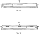
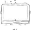
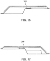
- FIGS. 10-18 show various front, back, top, bottom, side and sectional views of a perimeter cover 200 according to a second embodiment.
- the perimeter cover 200 according to the second embodiment has a more complex shape and includes a plurality of lateral tabs 202 each having a hole 204 therethrough for receiving a fastener for securing the perimeter cover 200 to a seatback component, such as the seatback shroud or frame member.
- the lateral tabs 202 may serve to secure the perimeter cover 200 in place, serve to secure the perimeter cover 200 and video monitor in place, or align with like tabs of the video monitor such that a single fastener through each hole secures both the video monitor and perimeter cover in place.
- the perimeter covers 110, 200 may be thermoformed or otherwise manufactured.
- inventive concepts disclosed herein are further directed to a method for preventing glass fragment escape in a direction forward of a glass screen of an aircraft seatback video monitor, including the steps of providing a video monitor having a glass screen having a film covering a front face of the glass screen, providing a perimeter cover having a frame portion adapted to overlap an outer perimeter of the front face of the glass screen of the video monitor continuously along a top, a bottom, a left side, and a right side of the front face of the glass screen, and bonding the perimeter cover to the film to provide a continuous seal between the frame portion of the perimeter cover and the overlapped portion of the front face of the glass screen.
Landscapes
- Engineering & Computer Science (AREA)
- Theoretical Computer Science (AREA)
- General Engineering & Computer Science (AREA)
- Physics & Mathematics (AREA)
- General Physics & Mathematics (AREA)
- Computer Hardware Design (AREA)
- Human Computer Interaction (AREA)
- Aviation & Aerospace Engineering (AREA)
- Devices For Indicating Variable Information By Combining Individual Elements (AREA)
- Laminated Bodies (AREA)
- Surface Treatment Of Glass (AREA)
Abstract
Description
- The present invention relates generally to preventing glass fragment escape from a shattered video monitor, and more particularly, to a monitor perimeter cover adapted to be affixed, bonded or otherwise attached to frame a glass monitor screen such that a continuous outer perimeter seal is provided between the monitor perimeter cover and the glass screen to prevent glass escape in one or more of forward and lateral directions away from the monitor screen.
- Aircraft are commonly equipped with video monitors for displaying information and passenger use during flight. Video monitors can be mounted to seatbacks, partitions, class dividers, deploy from overhead, etc. Seatback monitors, to which the present invention finds particular application, are within striking distance of the head of a facing passenger in the event of rapid deceleration or other emergency event. As such, the glass screen of a video monitor aboard an aircraft is required to be covered with a protective film to prevent shattered glass from releasing from the monitor and coming into contact with a passenger or crew.
- Regardless of the type of screen film applied, shattered glass fragments inevitably escape out through the sides of and ultimately forward of conventional video monitor assemblies. Therefore, to meet current aircraft crash test standards, what is needed is a containment solution that prevents any released glass fragments from escaping forward and/or laterally outward away from a video monitor.
- To achieve the foregoing and other aspects and advantages, in one aspect the inventive concepts disclosed herein are directed to a video monitor assembly including a video monitor including a glass screen having a film covering a front face of the glass screen, a perimeter cover affixed to the video monitor and having a frame portion overlapping an outer perimeter of the front face of the glass screen continuously along a top, a bottom, a left side, and a right side of the front face of the glass screen, and a continuous seal provided between the frame portion of the perimeter cover and the front face of the glass screen to prevent glass fragment escape in a direction forward of the glass screen.
- In another aspect, the frame portion of the perimeter cover may be bonded to the film covering the front face of the glass screen.
- In a further aspect, the frame portion of the perimeter cover may be adhesively bonded to the film covering the front face of the glass screen.
- In a further aspect, the film may be a PET film or a polycarbonate film.
- In a further aspect, the frame portion of the perimeter cover may overlap a minimum of 2.5 mm of the outer perimeter of the front face of the glass screen, measured from a lateral extent of an edge of the front face inward, along each of the top, the bottom, the left side, and the right side of the front face of the glass screen.
- In a further aspect, the perimeter cover may overlap at least one of a top, a bottom, a left side, and a right side of the video monitor to prevent glass fragment escape in a lateral direction away from the video monitor.
- In a further aspect, the video monitor includes a housing having at least one lateral tab having a hole for receiving a fastener therethrough for securing the video monitor assembly to a seatback.
- In a further aspect, the perimeter cover includes at least one lateral tab having a hole for receiving a fastener therethrough for securing the perimeter cover to a seatback.
- In a further aspect, the perimeter cover further includes at least one opening therethrough for accessing including bit not limited to at least one of a controller and an input jack of the video monitor.
- In a further aspect, the perimeter cover may be thermoformed.
- In another embodiment, the inventive concepts disclosed herein are directed to a monitor cover of a video monitor, preferably for an aircraft seatback monitor, including a frame adapted to be bonded to a perimeter portion of a front face of a glass screen covered with a film, the frame overlapping an outer perimeter of the front face of the glass screen continuously along a top, a bottom, a left side, and a right side of the front face of the glass screen to prevent glass fragment escape in at least a direction forward of the glass screen.
- In another embodiment, the inventive concepts disclosed herein are directed to a method for preventing glass fragment escape in a direction forward of a glass screen of an aircraft seatback video monitor, the method including the steps of providing a video monitor including a glass screen having a film covering a front face of the glass screen, providing a perimeter cover having a frame portion adapted to overlap an outer perimeter of the front face of the glass screen of the video monitor continuously along a top, a bottom, a left side, and a right side of the front face of the glass screen, and bonding the perimeter cover to the film to provide a continuous seal between the frame portion of the perimeter cover and the overlapped portion of the front face of the glass screen.
- In a further aspect, the step of bonding includes adhesive bonding.
- In a further aspect, the frame portion of the perimeter cover overlaps a minimum of 2.5 mm of the outer perimeter of the front face of the glass screen, measured from a lateral extent of an edge of the front face inward, along each of the top, the bottom, the left side, and the right side of the front face of the glass screen.
- In a further aspect, the perimeter cover includes at least one lateral tab having a hole for receiving a fastener therethrough for securing the perimeter cover to a seatback.
- Features, aspects and advantages of the present invention are understood when the following detailed description of the invention is read with reference to the accompanying drawings, in which:
-
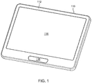
FIG. 1 is a front perspective view of a monitor cover according to a first embodiment; -
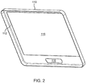
FIG. 2 is a rear perspective view of the monitor cover ofFIG. 1 ; -
FIG. 3 is a top view of the monitor cover ofFIG. 1 ; -
FIG. 4 is a bottom view of the monitor cover ofFIG. 1 ; -
FIG. 5 is a front view of the monitor cover ofFIG 1 ; -
FIG. 6 is a back view of the monitor cover ofFIG. 1 ; -
FIG. 7 is a top view of the monitor cover ofFIG. 1 ; -
FIG. 8 is a bottom view of the monitor cover ofFIG. 1 ; -
FIG. 9 is a cross-sectional view and detailed views of the monitor cover ofFIG. 1 taken along line 9-9 ofFIG. 5 ; -
FIG. 10 is a front perspective view of a monitor cover according to a second embodiment; -
FIG. 11 is a top perspective view of the monitor cover according toFIG. 10 ; -
FIG. 12 is a bottom view of the monitor cover according toFIG. 10 ; -
FIG. 13 is a top view of the monitor cover according toFIG. 10 ; -
FIG. 14 is a front view of the monitor cover ofFIG. 10 ; -
FIG. 15 is a back view of the monitor cover ofFIG. 10 ; -
FIG. 16 is a right side view of the monitor cover ofFIG. 10 ; -
FIG. 17 is a eft side view of the monitor cover ofFIG. 10 ; -
FIG. 18 is a cross-sectional view and detailed views of the monitor cover ofFIG. 10 taken along line 18-18 ofFIG. 14 ; and -
FIG. 19 is a perspective view of the monitor cover ofFIG. 1 shown installed on a seatback shroud for an aircraft passenger seat. - The inventive concepts disclosed herein are generally directed to a containment system for preventing glass fragments from a shattered glass screen of a video monitor from migrating or escaping at least forward of the video monitor. The containment system can further include side containment features for preventing glass fragment migration or escape in lateral directions away from the video monitor.
- The containment system generally includes a perimeter cover that frames the glass screen while overlapping a predetermined minimum amount of a continuous portion around the outer perimeter of the front face of the glass screen, and while leaving uncovered the majority of the glass screen for unobstructed viewing. The perimeter cover is affixed directly to the glass screen or protective film, such as by bonding, adhesive, tape, etc., thereby providing a continuous outer perimeter seal on the front face between the film and perimeter cover such that any free glass fragment released from the glass screen is contained by the monitor cover.
- The monitor cover can be installed by the original equipment manufacturer during video monitor manufacture, or can be applied thereafter to an existing video monitor. Suitable methods for affixing the monitor cover include, but are not limited to, bonding, glue, adhesive, tape, heat, etc. The external shape of the monitor cover may vary, for example for aesthetic reasons, while at least a portion of the frame and inner geometry of the cover may correspond to the shape of the underlying video monitor to provide a tight fit engagement therewith, at least with respect to the frame and the glass.
- Referring now to the drawings,
FIG. 19 illustrates aseatback shroud 100 configured to cover or close-out an upper portion of a seatback of an aircraft passenger seat. Theshroud 100 may be made from molded plastic or other durable material. Avideo monitor 102 is shown generally centered with respect to theshroud 100. Centering thevideo monitor 102 relative to theupper seatback shroud 100 advantageously positions thevideo monitor 102 in an ideal and ergonomic viewing position for an aft-seated passenger, while disadvantageously positioning thevideo monitor 102 in a head strike area in the event of rapid deceleration. - The
video monitor 102 generally includes a housing containing the electrical components, aglass screen 104, and apanel 106 containing controls and/or inputs. In a particular embodiment, the front face of theglass screen 104 is covered with aprotective film 108, such as a PET or polycarbonate film for abrasion resistance and/or glass fragment retention. - A
perimeter cover 110, also referred to herein as a "monitor cover" or "monitor perimeter cover," is affixed to thevideo monitor 102, and particularly theperimeter cover 110 is affixed to at least a portion of the front face of theglass screen 104. Theperimeter cover 110 may further be affixed to portions of the housing, or may tight-fit engage the housing. Theperimeter cover 110 includes a frame comprising aframe portion 112 that overlaps an outer perimeter of thefront face 114 of theglass screen 104 continuously along a top, a bottom, a left side, and a right side of the front face of the glass screen. As such, a continuous seal provided between theframe portion 112 of theperimeter cover 110 and the front face of theglass screen 104 to contain freed glass fragments, thus preventing glass fragment escape in at least a direction forward of the glass screen. - The
frame portion 112 of theperimeter cover 110 may be bonded to thefilm 108 covering thefront face 114 of theglass screen 104 such that glass fragment migration between the inner surface of theframe portion 112 and the film is prevented. In a particular embodiment, theframe portion 112 of the perimeter cover 110 overlaps a minimum of 2.5 mm all around the outer perimeter of thefront face 114 of theglass screen 104, measured from a lateral extent of an edge of the front face inward, along each of the top, the bottom, the left side, and the right side of the front face of the glass screen. In addition to thefront face 114, theperimeter cover 110 may overlap at least one of a top, a bottom, a left side, and a right side of the glass screen and video monitor to prevent glass fragment escape in lateral directions away from the video monitor, thus providing a comprehensive glass fragment containment system. -
FIGS. 1-9 show various front, back, top, bottom, side and sectional views of theperimeter cover 110 shown installed inFIG. 19 . Theperimeter cover 110 shown includes include afirst window 116 for viewing the viewable portion of the glass screen therethrough, and asecond window 118 through which thepanel 106 is accessed. -
FIGS. 10-18 show various front, back, top, bottom, side and sectional views of aperimeter cover 200 according to a second embodiment. In comparison to theperimeter cover 110 according to the first embodiment, theperimeter cover 200 according to the second embodiment has a more complex shape and includes a plurality oflateral tabs 202 each having ahole 204 therethrough for receiving a fastener for securing theperimeter cover 200 to a seatback component, such as the seatback shroud or frame member. Thelateral tabs 202 may serve to secure theperimeter cover 200 in place, serve to secure theperimeter cover 200 and video monitor in place, or align with like tabs of the video monitor such that a single fastener through each hole secures both the video monitor and perimeter cover in place. - The perimeter covers 110, 200 may be thermoformed or otherwise manufactured.
- The inventive concepts disclosed herein are further directed to a method for preventing glass fragment escape in a direction forward of a glass screen of an aircraft seatback video monitor, including the steps of providing a video monitor having a glass screen having a film covering a front face of the glass screen, providing a perimeter cover having a frame portion adapted to overlap an outer perimeter of the front face of the glass screen of the video monitor continuously along a top, a bottom, a left side, and a right side of the front face of the glass screen, and bonding the perimeter cover to the film to provide a continuous seal between the frame portion of the perimeter cover and the overlapped portion of the front face of the glass screen.
- Other embodiments and configurations may be devised without departing from the scope of the appended claims.
Claims (15)
- A monitor cover (110, 200) comprising a frame adapted to be bonded to a perimeter portion of a front face (114) of a glass screen (104) covered with a film (108), the frame comprising a frame portion (112), in use overlapping an outer perimeter of the front face (114) of the glass screen (104) continuously along a top, a bottom, a left side, and a right side of the front face (114) of the glass screen (104) to prevent glass fragment escape in at least a direction forward of the glass screen (104).
- A video monitor assembly, comprising:a video monitor (102) preferably an aircraft seatback monitor, comprising a glass screen (104) having a film (108) covering a front face (114) of the glass screen (104);a monitor cover according to claim 1, the cover being affixed to the video monitor (102), anda continuous seal provided between the frame portion (112) of the monitor cover (110, 200) and the front face (114) of the glass screen (104) to prevent glass fragment escape in a direction forward of the glass screen (104).
- The video monitor assembly according to claim 1 or 2, wherein the frame comprises a frame portion (112) of the monitor cover (110, 200) is bonded to the film (108) covering the front face (114) of the glass screen (104).
- The video monitor assembly according to one or more of claims 1-3, wherein the frame portion (112) of the monitor cover (110, 200) is adhesively bonded to the film (108) covering the front face (114) of the glass screen (104).
- The video monitor assembly according to one or more of claims 1-4, wherein the film (108) is a PET film or a polycarbonate film.
- The video monitor assembly according to one or more of claims 1-5, wherein the frame portion (112) of the monitor cover (110, 200) is adapted to overlap, or overlaps a minimum of 2.5 mm of the outer perimeter of the front face (114) of the glass screen (104), measured from a lateral extent of an edge of the front face (114) inward, along each of the top, the bottom, the left side, and the right side of the front face (114) of the glass screen (104).
- The video monitor assembly according to one or more of claims 1-6, wherein the monitor cover (110, 200) is adapted to overlap, or overlaps at least one of a top, a bottom, a left side, and a right side of the video monitor (102) to prevent glass fragment escape in a lateral direction away from the video monitor (102).
- The video monitor assembly according to one or more of claims 1-7, wherein the video monitor (102) comprises a housing having at least one lateral tab (202) having a hole (204) for receiving a fastener therethrough for securing the video monitor assembly to a seatback.
- The video monitor assembly according to one or more of claims 1-8, wherein the monitor cover (200) comprises at least one lateral tab (202) having a hole (204) for receiving a fastener therethrough for securing the monitor cover (200) to a seatback.
- The video monitor assembly according to one or more of claims 1-9, wherein the monitor cover (110, 200) further comprises an opening therethrough for accessing at least one of a controller and an input jack of the video monitor (102).
- The video monitor assembly according to one or more of claims 1-10, wherein the monitor cover (110, 200) is thermoformed.
- A method for preventing glass fragment escape in a direction forward of a glass screen (104) of an aircraft seatback video monitor (102), comprising the steps of:providing a video monitor (102) comprising a glass screen (104) having a film (108) covering a front face (114) of the glass screen (104);providing a monitor cover having a frame portion (112) adapted to overlap an outer perimeter of the front face (114) of the glass screen (104) of the video monitor (102) continuously along a top, a bottom, a left side, and a right side of the front face (114) of the glass screen (104); andbonding the monitor cover (110, 200) to the film (108) to provide a continuous seal between the frame portion (112) of the monitor cover (110, 200) and the overlapped portion of the front face (114) of the glass screen (104).
- The method according to claim 12, wherein the step of bonding includes adhesive bonding.
- The method according to claim 12 or 13, wherein the frame portion (112) of the monitor cover (110, 200) overlaps less than 2.5 mm of the outer perimeter of the front face (114) of the glass screen (104), measured from a lateral extent of an edge of the front face (114) inward, along each of the top, the bottom, the left side, and the right side of the front face (114) of the glass screen (104).
- The method according to one or more of claims 12-14, wherein the monitor cover (200) comprises at least one lateral tab (202) having a hole (204) for receiving a fastener therethrough for securing the monitor cover (200) to a seatback, and/or
wherein the monitor cover (110, 200) further comprises an opening therethrough for accessing at least one of a controller and an input jack of the video monitor (102).
Applications Claiming Priority (1)
| Application Number | Priority Date | Filing Date | Title |
|---|---|---|---|
| US15/921,209 US20190283369A1 (en) | 2018-03-14 | 2018-03-14 | Monitor glass perimeter cover |
Publications (2)
| Publication Number | Publication Date |
|---|---|
| EP3540559A1 true EP3540559A1 (en) | 2019-09-18 |
| EP3540559B1 EP3540559B1 (en) | 2022-01-12 |
Family
ID=65817793
Family Applications (1)
| Application Number | Title | Priority Date | Filing Date |
|---|---|---|---|
| EP19162905.4A Active EP3540559B1 (en) | 2018-03-14 | 2019-03-14 | Monitor glass perimeter cover |
Country Status (4)
| Country | Link |
|---|---|
| US (1) | US20190283369A1 (en) |
| EP (1) | EP3540559B1 (en) |
| JP (1) | JP2019179238A (en) |
| CN (1) | CN110277016A (en) |
Cited By (1)
| Publication number | Priority date | Publication date | Assignee | Title |
|---|---|---|---|---|
| CN112092742A (en) * | 2020-09-29 | 2020-12-18 | 金华阳学汽车科技有限公司 | Automobile data recorder capable of monitoring inside and outside of vehicle and provided with escape device |
Families Citing this family (3)
| Publication number | Priority date | Publication date | Assignee | Title |
|---|---|---|---|---|
| US10569718B2 (en) | 2018-02-12 | 2020-02-25 | Panasonic Avionics Corporation | Systems and methods for providing quick release of video monitors from an assembly |
| US10834837B2 (en) * | 2019-03-15 | 2020-11-10 | Panasonic Avionics Corporation | Systems and methods for monitor attachment |
| TWI854149B (en) * | 2021-08-20 | 2024-09-01 | 玻音先創科技股份有限公司 | Passive sounding device integrated into flat panel display |
Citations (4)
| Publication number | Priority date | Publication date | Assignee | Title |
|---|---|---|---|---|
| US20050146660A1 (en) * | 2004-01-07 | 2005-07-07 | Hai-Lin Wang | Liquid crystal displays |
| US20150202999A1 (en) * | 2012-08-23 | 2015-07-23 | Zodiac Seats Us Llc | Seatback energy management system |
| US20170024062A1 (en) * | 2015-07-21 | 2017-01-26 | Panasonic Avionics Corporation | Scratch resistant layer of ultra-thin glass on a substrate for touch sensitive display |
| WO2018035544A2 (en) * | 2016-08-19 | 2018-02-22 | Rockwell Collins, Inc. | Headrest-mounted electronic device holder |
Family Cites Families (8)
| Publication number | Priority date | Publication date | Assignee | Title |
|---|---|---|---|---|
| JP5042750B2 (en) * | 2006-11-07 | 2012-10-03 | 株式会社コロナ宣広社 | Front cover body of display panel |
| US9016627B2 (en) * | 2009-10-02 | 2015-04-28 | Panasonic Avionics Corporation | System and method for providing an integrated user interface system at a seat |
| EP2483150B1 (en) * | 2009-10-02 | 2014-01-01 | Panasonic Avionics Corporation | System and method for providing an integrated user interface system at a seat |
| US8164886B1 (en) * | 2010-04-22 | 2012-04-24 | Lockheed Martin Corporation | Ruggedized display enclosure |
| CN104317360B (en) * | 2011-06-13 | 2018-09-28 | 树蛙开发公司 | Shell for protecting tablet computer |
| KR101945890B1 (en) * | 2011-12-30 | 2019-02-12 | 삼성전자주식회사 | Display device |
| CA2820253C (en) * | 2012-08-08 | 2020-10-27 | Shrenik Shah | System and method for improving impact safety |
| JP2015145979A (en) * | 2014-02-04 | 2015-08-13 | 日本精機株式会社 | Display device for vehicle |
-
2018
- 2018-03-14 US US15/921,209 patent/US20190283369A1/en not_active Abandoned
-
2019
- 2019-03-14 JP JP2019047186A patent/JP2019179238A/en active Pending
- 2019-03-14 CN CN201910193047.7A patent/CN110277016A/en active Pending
- 2019-03-14 EP EP19162905.4A patent/EP3540559B1/en active Active
Patent Citations (4)
| Publication number | Priority date | Publication date | Assignee | Title |
|---|---|---|---|---|
| US20050146660A1 (en) * | 2004-01-07 | 2005-07-07 | Hai-Lin Wang | Liquid crystal displays |
| US20150202999A1 (en) * | 2012-08-23 | 2015-07-23 | Zodiac Seats Us Llc | Seatback energy management system |
| US20170024062A1 (en) * | 2015-07-21 | 2017-01-26 | Panasonic Avionics Corporation | Scratch resistant layer of ultra-thin glass on a substrate for touch sensitive display |
| WO2018035544A2 (en) * | 2016-08-19 | 2018-02-22 | Rockwell Collins, Inc. | Headrest-mounted electronic device holder |
Cited By (1)
| Publication number | Priority date | Publication date | Assignee | Title |
|---|---|---|---|---|
| CN112092742A (en) * | 2020-09-29 | 2020-12-18 | 金华阳学汽车科技有限公司 | Automobile data recorder capable of monitoring inside and outside of vehicle and provided with escape device |
Also Published As
| Publication number | Publication date |
|---|---|
| CN110277016A (en) | 2019-09-24 |
| EP3540559B1 (en) | 2022-01-12 |
| JP2019179238A (en) | 2019-10-17 |
| US20190283369A1 (en) | 2019-09-19 |
Similar Documents
| Publication | Publication Date | Title |
|---|---|---|
| EP3540559B1 (en) | Monitor glass perimeter cover | |
| US10682957B2 (en) | Laminated glass for vehicle with inner mirror | |
| US7108313B2 (en) | Trim assembly and method of manufacturing same | |
| US10639980B2 (en) | Window glass with seal member | |
| US9278617B2 (en) | Solar battery mounting structure for vehicle | |
| US11904689B2 (en) | Display device for vehicle | |
| RU2713965C2 (en) | Resistant to mechanical contact damages ultrathin glass layer on touch-screen substrate | |
| KR20150007281A (en) | Illuminated glazing for vehicle | |
| EP2888132B1 (en) | Seatback energy management system | |
| US10906272B2 (en) | Laminated vehicle-side window with a leadthrough for fastening a clamping element | |
| CN106054340A (en) | Glass lens assembly with elastic adhesive | |
| US10974645B2 (en) | Vehicle pane with a covered lighting device | |
| WO2006132736A1 (en) | Sealed structural passenger window assembly and method of forming same | |
| US6555042B1 (en) | Method of making a vehicle headliner assembly with integral speakers | |
| US10899428B2 (en) | Decompression panel assembly and methods of installation | |
| US6935677B2 (en) | Backlite retention system | |
| JPH09164948A (en) | Window structure for railway vehicles | |
| JP2013199187A (en) | Rear glass for vehicle, and method of mounting the same | |
| US7136030B2 (en) | Integrated window display | |
| US20200186746A1 (en) | Protective display monitor cover and method of making the same | |
| EP2591985A1 (en) | Panel-joining structure | |
| JPS593051A (en) | Window glass construction | |
| US20200298952A1 (en) | Optically enhanced aircraft window | |
| JPH05330343A (en) | Door trim with service hole cover | |
| US20050132661A1 (en) | Fastening assembly of a foil-coated vehicle glass pane and method of making same |
Legal Events
| Date | Code | Title | Description |
|---|---|---|---|
| PUAI | Public reference made under article 153(3) epc to a published international application that has entered the european phase |
Free format text: ORIGINAL CODE: 0009012 |
|
| STAA | Information on the status of an ep patent application or granted ep patent |
Free format text: STATUS: THE APPLICATION HAS BEEN PUBLISHED |
|
| AK | Designated contracting states |
Kind code of ref document: A1 Designated state(s): AL AT BE BG CH CY CZ DE DK EE ES FI FR GB GR HR HU IE IS IT LI LT LU LV MC MK MT NL NO PL PT RO RS SE SI SK SM TR |
|
| AX | Request for extension of the european patent |
Extension state: BA ME |
|
| STAA | Information on the status of an ep patent application or granted ep patent |
Free format text: STATUS: REQUEST FOR EXAMINATION WAS MADE |
|
| 17P | Request for examination filed |
Effective date: 20200317 |
|
| RBV | Designated contracting states (corrected) |
Designated state(s): AL AT BE BG CH CY CZ DE DK EE ES FI FR GB GR HR HU IE IS IT LI LT LU LV MC MK MT NL NO PL PT RO RS SE SI SK SM TR |
|
| GRAP | Despatch of communication of intention to grant a patent |
Free format text: ORIGINAL CODE: EPIDOSNIGR1 |
|
| STAA | Information on the status of an ep patent application or granted ep patent |
Free format text: STATUS: GRANT OF PATENT IS INTENDED |
|
| INTG | Intention to grant announced |
Effective date: 20211019 |
|
| GRAS | Grant fee paid |
Free format text: ORIGINAL CODE: EPIDOSNIGR3 |
|
| GRAA | (expected) grant |
Free format text: ORIGINAL CODE: 0009210 |
|
| STAA | Information on the status of an ep patent application or granted ep patent |
Free format text: STATUS: THE PATENT HAS BEEN GRANTED |
|
| AK | Designated contracting states |
Kind code of ref document: B1 Designated state(s): AL AT BE BG CH CY CZ DE DK EE ES FI FR GB GR HR HU IE IS IT LI LT LU LV MC MK MT NL NO PL PT RO RS SE SI SK SM TR |
|
| REG | Reference to a national code |
Ref country code: GB Ref legal event code: FG4D |
|
| REG | Reference to a national code |
Ref country code: CH Ref legal event code: EP |
|
| REG | Reference to a national code |
Ref country code: DE Ref legal event code: R096 Ref document number: 602019010766 Country of ref document: DE |
|
| REG | Reference to a national code |
Ref country code: IE Ref legal event code: FG4D |
|
| REG | Reference to a national code |
Ref country code: AT Ref legal event code: REF Ref document number: 1462812 Country of ref document: AT Kind code of ref document: T Effective date: 20220215 |
|
| REG | Reference to a national code |
Ref country code: LT Ref legal event code: MG9D |
|
| REG | Reference to a national code |
Ref country code: NL Ref legal event code: MP Effective date: 20220112 |
|
| REG | Reference to a national code |
Ref country code: AT Ref legal event code: MK05 Ref document number: 1462812 Country of ref document: AT Kind code of ref document: T Effective date: 20220112 |
|
| PG25 | Lapsed in a contracting state [announced via postgrant information from national office to epo] |
Ref country code: NL Free format text: LAPSE BECAUSE OF FAILURE TO SUBMIT A TRANSLATION OF THE DESCRIPTION OR TO PAY THE FEE WITHIN THE PRESCRIBED TIME-LIMIT Effective date: 20220112 |
|
| PG25 | Lapsed in a contracting state [announced via postgrant information from national office to epo] |
Ref country code: SE Free format text: LAPSE BECAUSE OF FAILURE TO SUBMIT A TRANSLATION OF THE DESCRIPTION OR TO PAY THE FEE WITHIN THE PRESCRIBED TIME-LIMIT Effective date: 20220112 Ref country code: RS Free format text: LAPSE BECAUSE OF FAILURE TO SUBMIT A TRANSLATION OF THE DESCRIPTION OR TO PAY THE FEE WITHIN THE PRESCRIBED TIME-LIMIT Effective date: 20220112 Ref country code: PT Free format text: LAPSE BECAUSE OF FAILURE TO SUBMIT A TRANSLATION OF THE DESCRIPTION OR TO PAY THE FEE WITHIN THE PRESCRIBED TIME-LIMIT Effective date: 20220512 Ref country code: NO Free format text: LAPSE BECAUSE OF FAILURE TO SUBMIT A TRANSLATION OF THE DESCRIPTION OR TO PAY THE FEE WITHIN THE PRESCRIBED TIME-LIMIT Effective date: 20220412 Ref country code: LT Free format text: LAPSE BECAUSE OF FAILURE TO SUBMIT A TRANSLATION OF THE DESCRIPTION OR TO PAY THE FEE WITHIN THE PRESCRIBED TIME-LIMIT Effective date: 20220112 Ref country code: HR Free format text: LAPSE BECAUSE OF FAILURE TO SUBMIT A TRANSLATION OF THE DESCRIPTION OR TO PAY THE FEE WITHIN THE PRESCRIBED TIME-LIMIT Effective date: 20220112 Ref country code: ES Free format text: LAPSE BECAUSE OF FAILURE TO SUBMIT A TRANSLATION OF THE DESCRIPTION OR TO PAY THE FEE WITHIN THE PRESCRIBED TIME-LIMIT Effective date: 20220112 Ref country code: BG Free format text: LAPSE BECAUSE OF FAILURE TO SUBMIT A TRANSLATION OF THE DESCRIPTION OR TO PAY THE FEE WITHIN THE PRESCRIBED TIME-LIMIT Effective date: 20220412 |
|
| PG25 | Lapsed in a contracting state [announced via postgrant information from national office to epo] |
Ref country code: PL Free format text: LAPSE BECAUSE OF FAILURE TO SUBMIT A TRANSLATION OF THE DESCRIPTION OR TO PAY THE FEE WITHIN THE PRESCRIBED TIME-LIMIT Effective date: 20220112 Ref country code: LV Free format text: LAPSE BECAUSE OF FAILURE TO SUBMIT A TRANSLATION OF THE DESCRIPTION OR TO PAY THE FEE WITHIN THE PRESCRIBED TIME-LIMIT Effective date: 20220112 Ref country code: GR Free format text: LAPSE BECAUSE OF FAILURE TO SUBMIT A TRANSLATION OF THE DESCRIPTION OR TO PAY THE FEE WITHIN THE PRESCRIBED TIME-LIMIT Effective date: 20220413 Ref country code: FI Free format text: LAPSE BECAUSE OF FAILURE TO SUBMIT A TRANSLATION OF THE DESCRIPTION OR TO PAY THE FEE WITHIN THE PRESCRIBED TIME-LIMIT Effective date: 20220112 Ref country code: AT Free format text: LAPSE BECAUSE OF FAILURE TO SUBMIT A TRANSLATION OF THE DESCRIPTION OR TO PAY THE FEE WITHIN THE PRESCRIBED TIME-LIMIT Effective date: 20220112 |
|
| PG25 | Lapsed in a contracting state [announced via postgrant information from national office to epo] |
Ref country code: IS Free format text: LAPSE BECAUSE OF FAILURE TO SUBMIT A TRANSLATION OF THE DESCRIPTION OR TO PAY THE FEE WITHIN THE PRESCRIBED TIME-LIMIT Effective date: 20220512 |
|
| REG | Reference to a national code |
Ref country code: DE Ref legal event code: R097 Ref document number: 602019010766 Country of ref document: DE |
|
| PG25 | Lapsed in a contracting state [announced via postgrant information from national office to epo] |
Ref country code: SM Free format text: LAPSE BECAUSE OF FAILURE TO SUBMIT A TRANSLATION OF THE DESCRIPTION OR TO PAY THE FEE WITHIN THE PRESCRIBED TIME-LIMIT Effective date: 20220112 Ref country code: SK Free format text: LAPSE BECAUSE OF FAILURE TO SUBMIT A TRANSLATION OF THE DESCRIPTION OR TO PAY THE FEE WITHIN THE PRESCRIBED TIME-LIMIT Effective date: 20220112 Ref country code: RO Free format text: LAPSE BECAUSE OF FAILURE TO SUBMIT A TRANSLATION OF THE DESCRIPTION OR TO PAY THE FEE WITHIN THE PRESCRIBED TIME-LIMIT Effective date: 20220112 Ref country code: MC Free format text: LAPSE BECAUSE OF FAILURE TO SUBMIT A TRANSLATION OF THE DESCRIPTION OR TO PAY THE FEE WITHIN THE PRESCRIBED TIME-LIMIT Effective date: 20220112 Ref country code: EE Free format text: LAPSE BECAUSE OF FAILURE TO SUBMIT A TRANSLATION OF THE DESCRIPTION OR TO PAY THE FEE WITHIN THE PRESCRIBED TIME-LIMIT Effective date: 20220112 Ref country code: DK Free format text: LAPSE BECAUSE OF FAILURE TO SUBMIT A TRANSLATION OF THE DESCRIPTION OR TO PAY THE FEE WITHIN THE PRESCRIBED TIME-LIMIT Effective date: 20220112 Ref country code: CZ Free format text: LAPSE BECAUSE OF FAILURE TO SUBMIT A TRANSLATION OF THE DESCRIPTION OR TO PAY THE FEE WITHIN THE PRESCRIBED TIME-LIMIT Effective date: 20220112 |
|
| REG | Reference to a national code |
Ref country code: CH Ref legal event code: PL |
|
| PLBE | No opposition filed within time limit |
Free format text: ORIGINAL CODE: 0009261 |
|
| STAA | Information on the status of an ep patent application or granted ep patent |
Free format text: STATUS: NO OPPOSITION FILED WITHIN TIME LIMIT |
|
| PG25 | Lapsed in a contracting state [announced via postgrant information from national office to epo] |
Ref country code: AL Free format text: LAPSE BECAUSE OF FAILURE TO SUBMIT A TRANSLATION OF THE DESCRIPTION OR TO PAY THE FEE WITHIN THE PRESCRIBED TIME-LIMIT Effective date: 20220112 |
|
| REG | Reference to a national code |
Ref country code: BE Ref legal event code: MM Effective date: 20220331 |
|
| 26N | No opposition filed |
Effective date: 20221013 |
|
| PG25 | Lapsed in a contracting state [announced via postgrant information from national office to epo] |
Ref country code: LU Free format text: LAPSE BECAUSE OF NON-PAYMENT OF DUE FEES Effective date: 20220314 Ref country code: LI Free format text: LAPSE BECAUSE OF NON-PAYMENT OF DUE FEES Effective date: 20220331 Ref country code: IE Free format text: LAPSE BECAUSE OF NON-PAYMENT OF DUE FEES Effective date: 20220314 Ref country code: CH Free format text: LAPSE BECAUSE OF NON-PAYMENT OF DUE FEES Effective date: 20220331 |
|
| PG25 | Lapsed in a contracting state [announced via postgrant information from national office to epo] |
Ref country code: SI Free format text: LAPSE BECAUSE OF FAILURE TO SUBMIT A TRANSLATION OF THE DESCRIPTION OR TO PAY THE FEE WITHIN THE PRESCRIBED TIME-LIMIT Effective date: 20220112 Ref country code: BE Free format text: LAPSE BECAUSE OF NON-PAYMENT OF DUE FEES Effective date: 20220331 |
|
| PG25 | Lapsed in a contracting state [announced via postgrant information from national office to epo] |
Ref country code: IT Free format text: LAPSE BECAUSE OF FAILURE TO SUBMIT A TRANSLATION OF THE DESCRIPTION OR TO PAY THE FEE WITHIN THE PRESCRIBED TIME-LIMIT Effective date: 20220112 |
|
| PG25 | Lapsed in a contracting state [announced via postgrant information from national office to epo] |
Ref country code: MK Free format text: LAPSE BECAUSE OF FAILURE TO SUBMIT A TRANSLATION OF THE DESCRIPTION OR TO PAY THE FEE WITHIN THE PRESCRIBED TIME-LIMIT Effective date: 20220112 Ref country code: CY Free format text: LAPSE BECAUSE OF FAILURE TO SUBMIT A TRANSLATION OF THE DESCRIPTION OR TO PAY THE FEE WITHIN THE PRESCRIBED TIME-LIMIT Effective date: 20220112 |
|
| PG25 | Lapsed in a contracting state [announced via postgrant information from national office to epo] |
Ref country code: HU Free format text: LAPSE BECAUSE OF FAILURE TO SUBMIT A TRANSLATION OF THE DESCRIPTION OR TO PAY THE FEE WITHIN THE PRESCRIBED TIME-LIMIT; INVALID AB INITIO Effective date: 20190314 |
|
| PG25 | Lapsed in a contracting state [announced via postgrant information from national office to epo] |
Ref country code: TR Free format text: LAPSE BECAUSE OF FAILURE TO SUBMIT A TRANSLATION OF THE DESCRIPTION OR TO PAY THE FEE WITHIN THE PRESCRIBED TIME-LIMIT Effective date: 20220112 |
|
| PG25 | Lapsed in a contracting state [announced via postgrant information from national office to epo] |
Ref country code: MT Free format text: LAPSE BECAUSE OF FAILURE TO SUBMIT A TRANSLATION OF THE DESCRIPTION OR TO PAY THE FEE WITHIN THE PRESCRIBED TIME-LIMIT Effective date: 20220112 |
|
| P01 | Opt-out of the competence of the unified patent court (upc) registered |
Free format text: CASE NUMBER: UPC_APP_0017956_3540559/2025 Effective date: 20251217 |
|
| PGFP | Annual fee paid to national office [announced via postgrant information from national office to epo] |
Ref country code: GB Payment date: 20260220 Year of fee payment: 8 |
|
| PGFP | Annual fee paid to national office [announced via postgrant information from national office to epo] |
Ref country code: DE Payment date: 20260219 Year of fee payment: 8 |
|
| PGFP | Annual fee paid to national office [announced via postgrant information from national office to epo] |
Ref country code: FR Payment date: 20260219 Year of fee payment: 8 |