EP3540532A1 - Control system and control method - Google Patents
Control system and control method Download PDFInfo
- Publication number
- EP3540532A1 EP3540532A1 EP18211275.5A EP18211275A EP3540532A1 EP 3540532 A1 EP3540532 A1 EP 3540532A1 EP 18211275 A EP18211275 A EP 18211275A EP 3540532 A1 EP3540532 A1 EP 3540532A1
- Authority
- EP
- European Patent Office
- Prior art keywords
- feature quantity
- control
- data
- unit
- control device
- Prior art date
- Legal status (The legal status is an assumption and is not a legal conclusion. Google has not performed a legal analysis and makes no representation as to the accuracy of the status listed.)
- Granted
Links
- 238000000034 method Methods 0.000 title claims abstract description 121
- 230000005856 abnormality Effects 0.000 claims abstract description 212
- 238000001514 detection method Methods 0.000 claims abstract description 198
- 238000012544 monitoring process Methods 0.000 claims abstract description 152
- 230000008569 process Effects 0.000 claims abstract description 98
- 238000012545 processing Methods 0.000 claims abstract description 74
- 230000010365 information processing Effects 0.000 claims abstract description 34
- 238000010801 machine learning Methods 0.000 claims abstract description 32
- 238000011156 evaluation Methods 0.000 claims description 47
- 125000004122 cyclic group Chemical group 0.000 claims description 45
- 238000003860 storage Methods 0.000 description 41
- 230000006870 function Effects 0.000 description 33
- 238000007418 data mining Methods 0.000 description 26
- 238000010586 diagram Methods 0.000 description 25
- 238000000605 extraction Methods 0.000 description 12
- 238000013480 data collection Methods 0.000 description 9
- 238000004891 communication Methods 0.000 description 8
- 238000004519 manufacturing process Methods 0.000 description 7
- 230000002159 abnormal effect Effects 0.000 description 5
- 230000008859 change Effects 0.000 description 5
- 238000012854 evaluation process Methods 0.000 description 4
- 230000018109 developmental process Effects 0.000 description 3
- 230000005540 biological transmission Effects 0.000 description 2
- 238000005516 engineering process Methods 0.000 description 2
- 239000000284 extract Substances 0.000 description 2
- 238000000513 principal component analysis Methods 0.000 description 2
- 238000004458 analytical method Methods 0.000 description 1
- 238000004364 calculation method Methods 0.000 description 1
- 238000011161 development Methods 0.000 description 1
- 238000009826 distribution Methods 0.000 description 1
- 238000005259 measurement Methods 0.000 description 1
- 238000012986 modification Methods 0.000 description 1
- 230000004048 modification Effects 0.000 description 1
- 230000003287 optical effect Effects 0.000 description 1
- 238000002360 preparation method Methods 0.000 description 1
- 230000004044 response Effects 0.000 description 1
- 238000000926 separation method Methods 0.000 description 1
- 239000007787 solid Substances 0.000 description 1
- 239000013589 supplement Substances 0.000 description 1
- 238000012546 transfer Methods 0.000 description 1
Images


Classifications
-
- G—PHYSICS
- G05—CONTROLLING; REGULATING
- G05B—CONTROL OR REGULATING SYSTEMS IN GENERAL; FUNCTIONAL ELEMENTS OF SUCH SYSTEMS; MONITORING OR TESTING ARRANGEMENTS FOR SUCH SYSTEMS OR ELEMENTS
- G05B13/00—Adaptive control systems, i.e. systems automatically adjusting themselves to have a performance which is optimum according to some preassigned criterion
- G05B13/02—Adaptive control systems, i.e. systems automatically adjusting themselves to have a performance which is optimum according to some preassigned criterion electric
- G05B13/0265—Adaptive control systems, i.e. systems automatically adjusting themselves to have a performance which is optimum according to some preassigned criterion electric the criterion being a learning criterion
-
- G—PHYSICS
- G05—CONTROLLING; REGULATING
- G05B—CONTROL OR REGULATING SYSTEMS IN GENERAL; FUNCTIONAL ELEMENTS OF SUCH SYSTEMS; MONITORING OR TESTING ARRANGEMENTS FOR SUCH SYSTEMS OR ELEMENTS
- G05B17/00—Systems involving the use of models or simulators of said systems
- G05B17/02—Systems involving the use of models or simulators of said systems electric
-
- G—PHYSICS
- G05—CONTROLLING; REGULATING
- G05B—CONTROL OR REGULATING SYSTEMS IN GENERAL; FUNCTIONAL ELEMENTS OF SUCH SYSTEMS; MONITORING OR TESTING ARRANGEMENTS FOR SUCH SYSTEMS OR ELEMENTS
- G05B19/00—Programme-control systems
- G05B19/02—Programme-control systems electric
- G05B19/04—Programme control other than numerical control, i.e. in sequence controllers or logic controllers
- G05B19/042—Programme control other than numerical control, i.e. in sequence controllers or logic controllers using digital processors
- G05B19/0428—Safety, monitoring
-
- G—PHYSICS
- G05—CONTROLLING; REGULATING
- G05B—CONTROL OR REGULATING SYSTEMS IN GENERAL; FUNCTIONAL ELEMENTS OF SUCH SYSTEMS; MONITORING OR TESTING ARRANGEMENTS FOR SUCH SYSTEMS OR ELEMENTS
- G05B19/00—Programme-control systems
- G05B19/02—Programme-control systems electric
- G05B19/04—Programme control other than numerical control, i.e. in sequence controllers or logic controllers
- G05B19/05—Programmable logic controllers, e.g. simulating logic interconnections of signals according to ladder diagrams or function charts
- G05B19/058—Safety, monitoring
-
- G—PHYSICS
- G05—CONTROLLING; REGULATING
- G05B—CONTROL OR REGULATING SYSTEMS IN GENERAL; FUNCTIONAL ELEMENTS OF SUCH SYSTEMS; MONITORING OR TESTING ARRANGEMENTS FOR SUCH SYSTEMS OR ELEMENTS
- G05B19/00—Programme-control systems
- G05B19/02—Programme-control systems electric
- G05B19/418—Total factory control, i.e. centrally controlling a plurality of machines, e.g. direct or distributed numerical control [DNC], flexible manufacturing systems [FMS], integrated manufacturing systems [IMS], computer integrated manufacturing [CIM]
- G05B19/41885—Total factory control, i.e. centrally controlling a plurality of machines, e.g. direct or distributed numerical control [DNC], flexible manufacturing systems [FMS], integrated manufacturing systems [IMS], computer integrated manufacturing [CIM] characterised by modeling, simulation of the manufacturing system
-
- G—PHYSICS
- G05—CONTROLLING; REGULATING
- G05B—CONTROL OR REGULATING SYSTEMS IN GENERAL; FUNCTIONAL ELEMENTS OF SUCH SYSTEMS; MONITORING OR TESTING ARRANGEMENTS FOR SUCH SYSTEMS OR ELEMENTS
- G05B23/00—Testing or monitoring of control systems or parts thereof
- G05B23/02—Electric testing or monitoring
- G05B23/0205—Electric testing or monitoring by means of a monitoring system capable of detecting and responding to faults
- G05B23/0218—Electric testing or monitoring by means of a monitoring system capable of detecting and responding to faults characterised by the fault detection method dealing with either existing or incipient faults
- G05B23/0224—Process history based detection method, e.g. whereby history implies the availability of large amounts of data
- G05B23/0227—Qualitative history assessment, whereby the type of data acted upon, e.g. waveforms, images or patterns, is not relevant, e.g. rule based assessment; if-then decisions
- G05B23/0229—Qualitative history assessment, whereby the type of data acted upon, e.g. waveforms, images or patterns, is not relevant, e.g. rule based assessment; if-then decisions knowledge based, e.g. expert systems; genetic algorithms
-
- G—PHYSICS
- G05—CONTROLLING; REGULATING
- G05B—CONTROL OR REGULATING SYSTEMS IN GENERAL; FUNCTIONAL ELEMENTS OF SUCH SYSTEMS; MONITORING OR TESTING ARRANGEMENTS FOR SUCH SYSTEMS OR ELEMENTS
- G05B23/00—Testing or monitoring of control systems or parts thereof
- G05B23/02—Electric testing or monitoring
- G05B23/0205—Electric testing or monitoring by means of a monitoring system capable of detecting and responding to faults
- G05B23/0218—Electric testing or monitoring by means of a monitoring system capable of detecting and responding to faults characterised by the fault detection method dealing with either existing or incipient faults
- G05B23/0224—Process history based detection method, e.g. whereby history implies the availability of large amounts of data
- G05B23/0227—Qualitative history assessment, whereby the type of data acted upon, e.g. waveforms, images or patterns, is not relevant, e.g. rule based assessment; if-then decisions
- G05B23/0235—Qualitative history assessment, whereby the type of data acted upon, e.g. waveforms, images or patterns, is not relevant, e.g. rule based assessment; if-then decisions based on a comparison with predetermined threshold or range, e.g. "classical methods", carried out during normal operation; threshold adaptation or choice; when or how to compare with the threshold
-
- G—PHYSICS
- G05—CONTROLLING; REGULATING
- G05B—CONTROL OR REGULATING SYSTEMS IN GENERAL; FUNCTIONAL ELEMENTS OF SUCH SYSTEMS; MONITORING OR TESTING ARRANGEMENTS FOR SUCH SYSTEMS OR ELEMENTS
- G05B2219/00—Program-control systems
- G05B2219/10—Plc systems
- G05B2219/13—Plc programming
- G05B2219/13174—Pc, computer connected to plc to simulate machine
-
- G—PHYSICS
- G05—CONTROLLING; REGULATING
- G05B—CONTROL OR REGULATING SYSTEMS IN GENERAL; FUNCTIONAL ELEMENTS OF SUCH SYSTEMS; MONITORING OR TESTING ARRANGEMENTS FOR SUCH SYSTEMS OR ELEMENTS
- G05B2219/00—Program-control systems
- G05B2219/10—Plc systems
- G05B2219/14—Plc safety
- G05B2219/14006—Safety, monitoring in general
-
- G—PHYSICS
- G05—CONTROLLING; REGULATING
- G05B—CONTROL OR REGULATING SYSTEMS IN GENERAL; FUNCTIONAL ELEMENTS OF SUCH SYSTEMS; MONITORING OR TESTING ARRANGEMENTS FOR SUCH SYSTEMS OR ELEMENTS
- G05B2223/00—Indexing scheme associated with group G05B23/00
- G05B2223/06—Remote monitoring
-
- Y—GENERAL TAGGING OF NEW TECHNOLOGICAL DEVELOPMENTS; GENERAL TAGGING OF CROSS-SECTIONAL TECHNOLOGIES SPANNING OVER SEVERAL SECTIONS OF THE IPC; TECHNICAL SUBJECTS COVERED BY FORMER USPC CROSS-REFERENCE ART COLLECTIONS [XRACs] AND DIGESTS
- Y02—TECHNOLOGIES OR APPLICATIONS FOR MITIGATION OR ADAPTATION AGAINST CLIMATE CHANGE
- Y02P—CLIMATE CHANGE MITIGATION TECHNOLOGIES IN THE PRODUCTION OR PROCESSING OF GOODS
- Y02P90/00—Enabling technologies with a potential contribution to greenhouse gas [GHG] emissions mitigation
- Y02P90/02—Total factory control, e.g. smart factories, flexible manufacturing systems [FMS] or integrated manufacturing systems [IMS]
Definitions
- the present disclosure relates to a control system and a control method for controlling a control target.
- FA factory automation
- PLC programmable logic controller
- ICT information and communication technology
- Patent Document 1 discloses a server including a machine learning device.
- the server including the machine learning device detects the presence or absence of failure or a degree of failure of a current device by executing machine learning using input data such as an output of a sensor provided in the device, which is received via a network.
- An objective of this disclosure is to provide an environment in which abnormality detection can be performed using reliable machine learning by a control device.
- a control system is a control system including a control device that controls a control target; and an information processing device capable of exchanging data with the control device, wherein the control device includes a computation processing unit that executes control computation of sequence control and motion control related to the control target; a collection unit that executes a process of collecting data associated with the control target; and a monitoring processing unit that executes a process of monitoring a state of the control target, the monitoring processing unit includes a feature quantity generation unit that executes a feature quantity generation process for generating a feature quantity from the data collected by the collection unit; and a detection unit that executes an abnormality detection process for detecting an abnormality occurring in the control target using the feature quantity generated by the feature quantity generation unit and an abnormality detection parameter suitable for detection of an abnormality occurring in the control target that is set based on a result of machine learning, and the information processing device includes a monitoring emulator that executes emulation of the monitoring process of the monitoring processing unit using the data associated with the control target from the control device.
- the monitoring process of the monitoring processing unit of the control device can be emulated by the monitoring processing emulator and the monitoring process of the monitoring processing unit of the control device can be reproduced in the information processing device. Therefore, it is possible to provide content of the reproduction as information for confirming whether or not abnormality detection based on reliable machine learning can be performed inside the control device.
- control device further includes a database that stores the data associated with the control target collected by the collection unit in time series, and the data associated with the control target that is used by the monitoring emulator of the information processing device includes data in the database of the control device.
- the information processing device can reproduce the monitoring process of the monitoring processing unit of the control device retroactively by performing emulation of the monitoring emulator using the time-series data stored (accumulated) in time series.
- the information processing device evaluates validity indicating whether or not the abnormality detection parameter held in the control device is suitable for detection of the abnormality occurring in the control target based on a result of the emulation of the monitoring process.
- control device further includes an execution management unit that cyclically executes collection of data of the collection unit and control computation of the computation processing unit and executes a cyclic execution process for causing collection of data of the collection unit and control computation of the computation processing unit to be executed with a higher priority than the monitoring process of the monitoring processing unit in the cyclic execution, wherein the information processing device includes a cyclic execution emulator that emulates the cyclic execution process of the execution management unit, and emulation of a monitoring process of the monitoring emulator is executed in the emulation of the cyclic execution process of the cyclic execution emulator.
- the information processing device can emulate the cyclic (periodical) execution of the control computation of the control device and evaluate the validity based on a result of the emulation of the monitoring process of the monitoring emulator in the cyclic execution.
- the information processing device evaluates validity indicating whether or not the abnormality detection parameter that is held in the control device is suitable for detection of an abnormality occurring in the control target, based on a result of the emulation of the cyclic execution process.
- the evaluation of the validity based on the result of the emulation of the cyclic execution process includes evaluation of the validity based on a result of a comparison between a time taken for emulation of the monitoring process in the emulation of the cyclic execution process and a length of the cycle.
- control device further includes a database that stores the data associated with the control target collected by the collection unit in time series
- information processing device further includes a time-series feature quantity generation unit that generates a feature quantity from time-series data of the data associated with the control target in the database of the control device, and a determination unit that determines an abnormality detection parameter suitable for detection of an abnormality occurring in the control target by performing machine learning using the feature quantity generated by the time-series feature quantity generation unit.
- the information processing device can generate the feature quantity from the time-series data of the data associated with the control target in the database of the control device, and determine an abnormality detection parameter suitable for detection of an abnormality occurring in the control target from the learning result of the machine learning using the generated feature quantity.
- the monitoring emulator includes a feature quantity generation emulator that executes emulation of a feature quantity generation process of the feature quantity generation unit
- the time-series feature quantity generation unit includes a unit that causes the feature quantity generation emulator to execute emulation of the feature quantity generation process using the time-series data in the database to generate a feature quantity from the time-series data.
- the information processing device causes the feature quantity generation emulator to execute emulation of the feature quantity generation process, such that the feature quantity can be generated from the time-series data.
- the abnormality detection parameter suitable for detection of the abnormality occurring in the control target includes a threshold value for classifying the feature quantity generated by the feature quantity generation unit into a class of feature quantities suitable for detection of the abnormality occurring in the control target.
- the threshold value for classifying the feature quantities into classes can be included in the abnormality detection parameter.
- control device holds a class of the feature quantity suitable for detection of the abnormality occurring in the control target, and the control device updates the feature quantity of the class using the feature quantity that is generated by the feature quantity generation unit during execution of the monitoring process.
- control device can update the feature quantity of the class using the feature quantity generated from the data collected from the control target, and the classification into classes using the updated class becomes possible.
- a control method is a control method that is executed by an information processing device capable of exchanging data with a control device that controls a control target
- the control device includes a computation processing unit that executes control computation of sequence control and motion control related to the control target, a collection unit that executes a process of collecting data associated with the control target, and a monitoring processing unit that executes a process of monitoring a state of the control target
- the monitoring processing unit includes a feature quantity generation unit that executes a feature quantity generation process for generating a feature quantity from the data collected by the collection unit; and a detection unit that executes an abnormality detection process for detecting an abnormality occurring in the control target using the feature quantity generated by the feature quantity generation unit and an abnormality detection parameter suitable for detection of an abnormality occurring in the control target that is set based on a result of machine learning
- the control method comprises receiving the data associated with the control target from the control device; and executing emulation of the monitoring process of the monitoring processing unit using the data associated with the control target received
- the monitoring process of the monitoring processing unit of the control device can be emulated by the monitoring processing emulator and the monitoring process of the monitoring processing unit of the control device can be reproduced in the information processing device. Therefore, it is possible to provide content of the reproduction as information for confirming whether or not abnormality detection based on reliable machine learning can be performed inside the control device.
- FIG. 4 is a schematic diagram illustrating an example of a situation in which a control system 1 according to the embodiment is applied.
- the control device 100 controls an arbitrary control target (for example, a manufacturing device or equipment included in a production line).
- FIG. 4 schematically illustrates functions that are provided by respective devices of the control system 1.
- the control system 1 includes a control device 100 that controls a control target and a support device 200 that can exchange data with the control device 100.
- the control device 100 corresponds to an industrial controller such as a PLC that controls control targets such as various facilities or devices.
- the PLC is a type of computer that executes a control computation.
- the support device 200 provides a user with, for example, an environment for developing a module (typically, data, programs, or the like) included in the control device 100 or an environment for monitoring a state of the control device 100.
- the support device 200 includes an example of the "information processing device" and typically includes a general-purpose computer.
- the control device 100 includes a computation processing unit that executes control computation of sequence control and motion control related to a control target, a collection unit that executes a process of collecting data (raw data 132) associated with the control target, and a monitoring processing unit that executes a process of monitoring a state of the control target.
- a PLC engine 150 executes a variable manager 154 corresponding to a "collection unit” to collect data associated with the control target while executing a sequence/motion program 162 corresponding to the "control computation.”
- the "monitoring processing unit” includes a feature quantity generation unit that executes a feature quantity generation process of generating a feature quantity from the collected data, and an abnormality detection engine 140.
- the feature quantity generation unit corresponds to a feature quantity generation program 174, and the feature quantity generation process is executed by executing the feature quantity generation program 174.
- the abnormality detection engine 140 executes an abnormality detection process of detecting an abnormality occurring in a control target using the feature quantity generated by the feature quantity generation unit and an abnormality detection parameter 136 or learning data 134 suitable for detection of an abnormality held in an internal DB 130.
- the abnormality detection parameter 136 or the learning data 134 is based on a learning result of machine learning of the support device 200.
- the support device 200 includes a monitoring processing emulator 2272 that executes emulation of the "monitoring processing unit" using the data associated with the control target from the control device 100.
- the monitoring processing emulator 2272 executes an instruction to emulate the feature quantity generation program 174 and a program of the abnormality detection engine 140 in a processor environment that is provided by a computer of the support device 200. Accordingly, the "monitoring processing unit" of the control device 100 is emulated in the support device 200.
- the monitoring process of the "monitoring processing unit" of the control device 100 can be emulated by the monitoring processing emulator 2272 and the monitoring process of the "monitoring processing unit” of the control device 100 can be reproduced in the support device 200. Therefore, it is possible to provide content of the reproduction as information for confirming whether or not reliable machine learning can be performed inside the control device 100.
- the "collection unit" of the control device 100 corresponds to the variable manager 154.
- the variable manager 154 collects data of a user variable and device variable 1544 that is updated by an I/O refresh process that is cyclically executed, in synchronization with the cycle.
- the collected data is used for the above monitoring process and is stored as time-series raw data 132 in an order of collection (detection) in a time-series DB 131.
- a time-series DB program 163 adds a time stamp to the raw data 132 collected by the collection unit in the order of collection (detection), and stores the resultant raw data in the time-series DB 131.
- This time stamp can be assigned in units of time that can be variably set, such as units of control cycles, units of works, or units of takt time.
- the data associated with the control target that is used by the monitoring processing emulator 2272 of the support device 200 includes the time-series raw data 132 in the time-series DB 131 of the control device 100.
- the emulation in the support device 200 is performed using the time-series raw data 132 in the time-series DB 131.
- the support device 200 can reproduce the monitoring process of the "monitoring processing unit" of the control device 100 retroactively.
- the support device 200 is capable of exchanging data including the time-series raw data 132 in the time-series DB 131 with the control device 100.
- a data access unit 2262 of the support device 200 can exchange data with the control device 100 via a storage medium such as a memory card in which the raw data 132 has been stored.
- the support device 200 can receive the time-series raw data 132 in the time-series DB 131 without causing data loss due to a communication error. Therefore, in the support device 200, it is possible to improve accuracy of the reproducibility using the emulation.
- the exchange of data between the support device 200 and the control device 100 is not limited to a method in which the exchange is via the storage medium.
- the support device 200 further includes an evaluation unit 2270 that evaluates validity indicating whether or not the abnormality detection parameter 136 held in the control device 100 is suitable for detection of an abnormality occurring in the control target based on a result of the emulation of the monitoring process.
- the support device 200 emulates cyclic execution of the control computation of the control device 100 and evaluates the validity based on a result of the emulation.
- the control device 100 cyclically executes the collection (the variable manager 154) of the data associated with the control target and control computation (the sequence/motion program 162) according to a computation process.
- the control device 100 further includes an execution management unit (a scheduler 152) that executes a cyclic execution process for executing the collection of the data associated with the control target and the control computation according to the computation process with a higher priority than the "monitoring process" (the feature quantity generation program 174 and the abnormality detection engine 140).
- the support device 200 includes a PLC emulator 2260 that emulates the PLC engine 150.
- the PLC emulator 2260 includes a cyclic execution emulator (a scheduler emulator 2269) that emulates the cycle execution process of the execution management unit (the scheduler 152).
- a control program emulator 2265 a monitoring processing emulator 2272 including a feature quantity generation program emulator 2266
- a system program emulator 2267 including a variable manager emulator 2268
- the support device 200 can evaluate the validity of the abnormality detection parameter 136 based on an execution result (content of reproduction) of the emulation of the monitoring process in the emulation of the cyclic execution of the control computation of the control device 100.
- the evaluation unit 2270 when the evaluation unit 2270 evaluates the validity based on the result of the emulation of the cyclic execution process, the evaluation unit 2270 can evaluate the validity based on a result of comparison of a time taken for the emulation of the monitoring process in the emulation of the cyclic execution process with a length of a cycle of the cyclic execution.
- control system 1 According to the embodiment, a more detailed configuration and a process of the control system 1 according to the embodiment will be described as a more specific application example of the present disclosure.
- FIG. 1 is a schematic diagram illustrating an example of the overall configuration of a control system 1 according to the embodiment.
- the control system 1 includes a control device 100 that controls a control target, and a support device 200 that can be connected to control device 100, as main components.
- the support device 200 exchanges data with the control device 100 through communication or a storage medium.
- the control device 100 may be embodied as a type of computer such as a programmable logic controller (PLC).
- PLC programmable logic controller
- the control device 100 is connected to a field device group 10 via a first field network 2 and to one or a plurality of display devices 400 via a second field network 4. Further, the control device 100 is connected to a data logging device 600 via a local network 6.
- the control device 100 exchanges data with the connected devices via the respective networks. It should be noted that the data logging device 600 and the display devices 400 are optional configurations and are not indispensable components of the control system 1.
- the control device 100 includes a control logic (hereinafter also referred to as a "PLC engine”) that executes various computations for controlling a facility or machine.
- PLC engine a control logic
- the control device 100 also has a collection function of collecting data (hereinafter also referred to as "input data") measured by the field device group 10 and transferred to the control device 100). Further, the control device 100 also has a monitoring function of monitoring the collected input data. By causing the control device 100 to have these functions, it is possible to monitor a phenomenon occurring in the control target at shorter cycles.
- an internal database 130 mounted in the control device 100 provides the collection function
- the abnormality detection engine 140 mounted in the control device 100 provides the monitoring function. Details of the internal DB 130 and the abnormality detection engine 140 will be described later.
- EtherCAT registered trademark
- EtherNet/IP registered trademark
- DeviceNet registered trademark
- CompoNet registered trademark
- the field device group 10 includes a device that collects input data from the control target or a manufacturing device, a production line, or the like related to control (hereinafter also referred to as a "field").
- An input relay, various sensors, or the like are assumed as such a device that collects input data.
- the field device group 10 further includes a device that gives some actions to the field based on a command (hereinafter also referred to as "output data") generated by the control device 100.
- An output relay, a contactor, a servo driver, a servo motor, and another arbitrary actuator are assumed as such a device that gives some actions to the field.
- the field device group 10 exchanges data including the input data and the output data with the control device 100 via the first field network 2.
- the field device group 10 includes a remote input/output (I/O) device 12, a relay group 14, an image sensor 18, a camera 20, a servo driver 22, and a servo motor 24.
- I/O remote input/output
- relay group 14 an image sensor 18, a camera 20, a servo driver 22, and a servo motor 24.
- the remote I/O device 12 includes a communication unit that performs communication via the first field network 2, and an input/output unit (hereinafter referred to as an "I/O unit") for performing acquisition of input data and output of output data.
- the input data and the output data are exchanged between the control device 100 and the field via such an I/O unit.
- An example in which digital signals are exchanged as input data and output data via the relay group 14 is illustrated in FIG. 1 .
- the I/O unit may be directly connected to the field network.
- An example in which the I/O unit 16 is directly connected to the first field network 2 is illustrated in FIG. 1 .
- the image sensor 18 performs an image measurement process such as pattern matching on image data captured by the camera 20 and transmits a result of the process to the control device 100.
- the servo driver 22 drives the servo motor 24 according to output data (for example, a position command) from the control device 100.
- the display device 400 connected to the control device 100 via the second field network 4 transmits, for example, a command according to a user operation to the control device 100 in response to an operation from the user, and graphically displays, for example, a result of computation in the control device 100.
- the data logging device 600 is connected to the control device 100 via the local network 6, and exchanges necessary data with the control device 100.
- the data logging device 600 has, for example, a database function, and collects, for example, event logs that are generated by the control device 100, in a time-series.
- a general-purpose protocol such as Ethernet (registered trademark) may be mounted on the local network 6. That is, typically, a transmission cycle or an updating cycle of data in the local network 6 may be later than a transmission cycle or an updating cycle of data in the field network (the first field network 2 and the second field network 4). However, the local network 6 may be able to transmit more data at the same time than the field network.
- the support device 200 is a device that supports preparation necessary for the control device 100 to control the control target.
- the support device 200 provides, for example, a program development environment (a program creation and editing tool, a parser, a compiler, or the like) for a program that is executed by the control device 100, a setting environment for setting parameters (configuration) of the control device 100 and various devices connected to the control device 100, a function of transmitting a generated user program to the control device 100, and a function of correcting and changing, online, the user program or the like that is executed on the control device 100.
- a program development environment a program creation and editing tool, a parser, a compiler, or the like
- the support device 200 determines, for example, the abnormality detection parameter 136 using the time-series raw data 132, to be described later, of the internal DB 130 mounted in the control device 100, and also provides an environment in which the abnormality detection engine 140 is emulated. Details of this emulation will be described later.
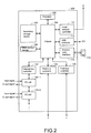
- FIG. 2 is a block diagram illustrating an example of a hardware configuration of the control device 100 constituting the control system 1 according to the embodiment.
- the control device 100 includes, for example, a processor 102 such as central processing unit (CPU) or a micro-processing unit (MPU), a chipset 104, a main storage device 106, a secondary storage device 108, a local network controller 110, a Universal Serial Bus (USB) controller 112, a memory card interface 114, an internal bus controller 122, field bus controllers 118 and 120, I/O units 124-1 and 124-2.
- a processor 102 such as central processing unit (CPU) or a micro-processing unit (MPU), a chipset 104, a main storage device 106, a secondary storage device 108, a local network controller 110, a Universal Serial Bus (USB) controller 112, a memory card interface 114, an internal bus controller 122, field bus controllers 118 and 120, I/O units 124-1 and 124
- the processor 102 reads various programs stored in the secondary storage device 108, develops the programs in the main storage device 106, and executes the programs, thereby realizing control according to the control target and various processes to be described later.
- the chipset 104 realizes a process of the entire control device 100 by controlling the processor 102 and each component.
- the secondary storage device 108 stores a user program to be executed using the PLC engine, in addition to a system program for realizing the PLC engine. Further, a program for realizing the internal DB 130 and the abnormality detection engine 140 is also stored in the secondary storage device 108.
- the local network controller 110 controls exchange of data with other devices via the local network 6.
- the USB controller 112 controls exchange of data with the support device 200 via a USB connection.
- the memory card interface 114 is configured such that a memory card 116 can be attached and detached, and data can be written to the memory card 116 and various pieces of data (a user program, trace data, or the like) can be read from the memory card 116.
- the internal bus controller 122 is an interface that exchanges data with the I/O units 124-1, 124-2, ... mounted in the control device 100.
- the field bus controller 118 controls exchange of data with other devices via the first field network 2.
- the field bus controller 120 controls exchange of data with other devices via the second field network 4.
- main units of the control device 100 may be realized using hardware conforming to a general-purpose architecture (for example, an industrial personal computer based on a general-purpose personal computer).
- OSs operating systems
- the support device 200 is realized, for example, by executing a program using hardware (for example, a general-purpose personal computer) conforming to a general-purpose architecture.
- hardware for example, a general-purpose personal computer
- FIG. 3 is a block diagram illustrating an example of a hardware configuration of the support device 200 constituting the control system 1 according to the embodiment.
- the support device 200 includes a processor 202 such as a CPU or an MPU, a drive 204, a main storage device 206, a secondary storage device 208, a USB controller 212, a local network controller 214, an input unit 216, and a display unit 218. These components are connected via a bus 220.
- the processor 202 reads various programs stored in the secondary storage device 208, opens the programs in the main storage device 206, and executes the programs, thereby realizing various processes as will be described later.
- the secondary storage device 208 includes, for example, a hard disk drive (HDD) or a flash solid state drive (SSD).
- various programs including a development program (not illustrated) for performing creation of a user program to be executed in the support device 200, debug of the created program, definition of a system configuration, setting of various parameters, and the like, and an emulator tool 225 including instruction codes for executing a data mining tool 226 and a PLC emulator 2260 to be described later are stored in the secondary storage device 208.
- An area of an internal DB 224 that stores data related to the data mining tool 226 is provided in the secondary storage device 208.
- the secondary storage device 208 may store an OS and other necessary programs.
- the data mining tool 226 includes a program or a combination of a program and data for realizing data mining in the support device 200.
- the drive 204 is configured such that the memory card 116 or the storage medium 205 can be attached and detached.
- the drive 204 can write data to the memory card 116 or the storage medium 205 and can read various pieces of data (user program, trace data, time-series data, or the like) from the memory card 116 or the storage medium 205.
- the storage medium 205 includes, for example, the storage medium 205 (for example, an optical storage medium such as a digital versatile disc (DVD)) that non-transitorily stores a computer-readable program.
- the stored program or data is read from the memory card 116 or the storage medium 205 and installed in an internal storage area of the secondary storage device 208 or the like.
- various programs that are executed by the support device 200 may be installed via the computer-readable memory card 116 or storage medium 205, the programs may be installed in a form in which the programs are downloaded from, for example, a server device on a network.
- functions that are provided by the support device 200 according to the embodiment may be realized in a form in which some modules that are provided by an OS are used.
- the USB controller 212 controls exchange of data with the control device 100 via a USB connection.
- the local network controller 214 controls exchange of data with another device via an arbitrary network.
- Data that the USB controller 212 exchanges with the control device 100 includes, for example, the time-series raw data 132, the abnormality detection parameter 136, and the learning data 134 in the time-series DB 131.
- the input unit 216 includes a keyboard, a mouse, or the like, and receives a user operation.
- the display unit 218 includes a display, various indicators, and the like, and outputs, for example, a processing result from the processor 202.
- a printer may be connected to the support device 200.
- FIG. 3 Although an example of a configuration in which necessary functions are provided by the processor 202 executing a program has been illustrated in FIG. 3 , some or all of these provided functions may be provided by using a dedicated hardware circuit (for example, an ASIC or an FPGA).
- a dedicated hardware circuit for example, an ASIC or an FPGA.
- the data logging device 600 constituting the control system 1 according to the embodiment can be realized, for example, by using a general-purpose file server or a database server. Since a hardware configuration of such a device is well known, detailed description thereof will not be given here.
- the display device 400 constituting the control system 1 according to the embodiment is referred to as a human machine interface (HMI) device.
- HMI human machine interface
- a configuration in which the display device 400 is mounted as a dedicated device may be adopted.
- the display device 400 may be realized using hardware according to a general-purpose architecture (for example, an industrial personal computer conforming to a general-purpose personal computer).
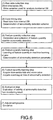
- FIG. 5 is a schematic diagram illustrating a procedure of abnormality detection using the control device 100 according to the embodiment.
- the abnormality detection procedure illustrated in FIG. 5 includes five steps as a whole.
- a raw data collection step (1) is first performed.
- data raw data 132 that is used for analysis related to abnormality detection among data that is handled by the control device 100 is written in the internal DB 130.
- the raw data collection step (1) is realized by executing an internal DB access program 164 of the control device 100 which will be described later.
- a unique variable name is allocated to each of data (input data and output data) that is exchanged with the field and internal data, and a user program or the like is described using each variable name. That is, in the control device 100, an environment in which variable programming is possible is provided. Therefore, in the following description, representations "designation of the variable” or “specifying of the variable” are used substantially synonymously with specifying data that is a target. It should be noted that the scope of the present invention is not limited to a configuration in which the variable is programmable, and a configuration in which an address in a memory is directly designated can be included in the technical scope.
- a time-series DB storage step (2) of storing the collected raw data 132 in the time-series DB 131 in time series is then performed.
- the time-series DB program 163 stores the collected raw data 132 in the time-series DB 131 while assigning a time stamp to the raw data 132.
- the time stamp corresponds to a time when the raw data 132 is collected (detected).
- a feature quantity generation step (3) is then performed.
- a predetermined feature quantity generation scheme is applied to data that is a target among data exchanged with the field and internal data, thereby sequentially generating feature quantities.
- the feature quantity generation step (3) is realized by executing a feature quantity generation program 174 of the control device 100 which will be described later.
- an abnormality detection scheme suitable for detection of an abnormality occurring in a control target is determined by the support device 200.
- the abnormality detection scheme indicates a scheme capable of detecting a desired abnormality when certain data is monitored with a certain logic.
- the abnormality detection scheme includes a scheme of generating feature quantities from one or a plurality of pieces of raw data 132 from the field.
- the support device 200 determines the abnormality detection scheme by executing the data mining tool. According to the determined abnormality detection scheme, settings, parameters, or the like for generating the feature quantity are output.
- a feature quantity extraction step (4) is then performed.
- the feature quantity extraction step (4) based on a type of feature quantity indicated by the abnormality detection parameter 136, that is, a type of feature quantity suitable for detection of the abnormality occurring in the control target, the feature quantity of the type is extracted (selected) from the feature quantities generated in the feature quantity generation step (3).
- the feature quantity extraction step (4) is realized by the feature quantity extraction unit 142 of the abnormality detection engine 140.
- an abnormality detection step (5) is performed.
- the abnormality detection step (5) with respect to the feature quantity of the type selected in the feature quantity extraction step (4), the feature quantity generated in each predetermined cycle or each predetermined event is monitored, that is, an abnormality is detected from the feature quantity based on the abnormality detection parameter 136 and the learning data 134.
- a score value 147 indicating a degree to which the feature quantity of the type selected in the feature quantity extraction step is to be classified into the class indicated by the learning data 134 is calculated.
- the score value 147 is compared with a threshold value indicated by the abnormality detection parameter 136, and when the score value 147 crosses (exceeds) the threshold value, an abnormality is detected. Further, the score value 147 in this case is stored in the internal DB 130. Further, when an abnormality is detected, an event log 146 is output.
- the abnormality detection step (5) is realized by the abnormality detection unit 144 of the abnormality detection engine 140.
- the abnormality detection parameter 136 includes a type of feature quantity that is a monitoring target and the threshold value suitable for detection of an abnormality occurring in the control target, which is determined by the support device 200 executing the data mining tool 226.
- the monitoring process in the control device 100 may include the feature quantity extraction step (4) and the abnormality detection step (5) in FIG. 5 .
- the time-series DB storage step (2) is included in a series of steps in FIG. 5 for description, but is a step that can be executed concurrently with other steps.
- the control device 100 can perform a process of monitoring the control target, that is, selection of a feature quantity suitable for detection of an abnormality occurring in the control target and detection of an abnormality occurring in the control target using the selected feature quantity using the abnormality detection parameter 136 and the learning data 134.
- setting (the abnormality detection parameter 136 and the learning data 134) necessary for the monitoring process is performed based on the raw data 132 associated with the control target collected by the control device 100 using the data mining tool 226 included in the support device 200.
- FIG. 6 is a schematic diagram illustrating a data mining procedure in the support device 200 according to the embodiment.
- a feature quantity monitoring step (5) and an evaluation step (6) that are performed by the support device 200 are illustrated in association with steps (1) to (4) of the data mining procedure.
- a raw data collection step (1) is performed.
- the raw data 132 in the time-series DB 131 of the control device 100 for example, is transferred to the support device 200 via the memory card 116 and stored in the internal DB 224 such as the secondary storage device 208.
- the raw data collection step (1) is realized by the data access unit 2262 of the support device 200. Specifically, the data access unit 2262 accesses (reads) the memory card 116 via the drive 204 and stores the read raw data 132, for example, in the internal DB 224 such as the secondary storage device 208.
- a data mining step (2) is performed.
- the time-series raw data 132 written to the internal DB 224 is read, and an abnormality detection scheme is determined.
- the user operates the support device 200 using the data mining tool 226 and reads and analyzes the raw data 132 collected in the internal DB 224 to determine a feature quantity generation scheme and an abnormality detection scheme.
- a feature quantity generation step (3) is then executed.
- the feature quantity generation scheme determined in the data mining step (2) is applied to generate the feature quantity from the time-series raw data 132 of the internal DB 224.
- the feature quantity generation step (3) is realized by the feature quantity generation program emulator 2266 of the support device 200 emulating the feature quantity generation program 174 using the time-series raw data 132 of the internal DB 224.
- a feature quantity learning step (4) is executed.
- machine learning is performed on the feature quantity generated in the feature quantity generation step (3), and the abnormality detection parameter 136 and the learning data 134 are determined from a result of the machine learning.
- the parameter determination unit 2263 of the support device 200 determines the abnormality detection parameter 136
- the learning data determination unit 2261 determines the learning data 134.
- the abnormality detection parameter 136 includes a type or a determination index (typically, a threshold value or the like) of a feature quantity suitable for detection of an abnormality occurring in a control target.
- the feature quantity learning step (4) is realized by the determination unit 2264 using the machine learning engine of the support device 200.
- FIG. 7 is a diagram schematically illustrating an example of a list showing feature quantities that can be determined in the data mining step of the control system 1 according to the embodiment.
- a plurality of feature quantities as illustrated in FIG. 7 are defined in advance, and a type of feature quantity that is preferably used for the raw data 132 collected in the internal DB 224 of the support device 200 is determined.
- the parameter determination unit 2263 calculates respective feature quantities illustrated in FIG. 7 using the raw data 132 collected in the internal DB 224, and determines the feature quantities having a higher correlation or relationship as candidates. Further, the learning data determination unit 2261 generates the learning data 134 which is a class consisting of a set of feature quantities of a type determined by the parameter determination unit 2263. Details of generation of the learning data 134 will be described later.
- the support device 200 can determine a definition of the feature quantity that is used for abnormality detection, and the abnormality detection parameter 136, the learning data 134, and the like for determining that there is an abnormality.
- a feature quantity monitoring step (5) and an evaluation step (6) are performed in the support device 200.
- the time-series raw data 132, the score value 147, and the event log 146 are acquired from the control device 100 via the memory card 116 or the like, and stored in the internal DB 224 or the like.
- the acquisition of the data in the feature quantity monitoring step (5) is realized by the data access unit 2262, for example.
- an evaluation step (6) validity indicating whether or not the abnormality detection parameter 136 or the learning data 134 that is used for abnormality detection, that is, held in the control device 100, is suitable for detection of an abnormality occurring in the control target is evaluated.
- the evaluation step (6) is typically realized by the evaluation unit 2270 of the support device 200.
- the adjustment unit 2271 performs adjustment (change) of the abnormality detection parameter 136 or the learning data 134 that is held in the control device 100. For example, the adjustment unit 2271 performs the adjustment based on the evaluation result of the evaluation unit 2270. The evaluation and the adjustment in the evaluation unit 2270 and the adjustment unit 2271 of the support device 200 will be described later.
- a control program (user program) used in the feature quantity collection step (3) and the feature quantity learning step (4) in FIG. 6 will be described with reference to FIG. 8 .
- FIG. 8 is a diagram schematically illustrating an example of the feature quantity generation program and a program of the learning data determination unit according to the embodiment.
- the feature quantity generation program 174 that is emulated by the feature quantity generation program emulator 2266 may be typically described using a feature quantity generation function block 1742.
- the feature quantity generation function block 1742 is a functional module that generates a feature quantity from the raw data 132.
- an input variable designation 1744 for specifying a variable that is used for calculation of the feature quantity and an output destination designation 1746 indicating an output destination of the calculated feature quantity are defined.
- a functional block 1682 for executing a process corresponding to the learning data determination unit 2261 of the machine learning engine may be connected to an output stage (the output destination designation 1746) of the feature quantity generation function block 1742. That is, the output destination designation 1746 of the feature quantity generation function block 1742 is connected to input variable designation 1684 for designating a variable serving as the feature quantity of the learning target of the functional block 1682.
- Information obtained as a result of the machine learning that is, the learning data 134, is output in an output stage (learning result output destination designation 1686) of the functional block 1682.
- FIG. 9 is a diagram schematically illustrating an example of the learning data 134 according to the embodiment.
- FIG. 9 is a diagram illustrating an example of a feature quantity space that is represented by a feature quantity obtained by plotting, in a corresponding coordinate space, samples of a feature quantity (usually, a feature quantity vector including a plurality of feature quantities) that is generated from the raw data 132. This feature quantity space corresponds to the learning data 134.
- a label (normality or abnormality) is assigned to each feature quantity, and the user determines a range indicated by a dashed line defined by a threshold value 304 defining a class consisting of a set of feature quantities when the control target is in a normal state and/or a class consisting of a set of feature quantities when the control target is in an abnormal state while referring to the label assigned to each feature quantity.
- the user may designate a reference position (a mark x in FIG. 9 ) which is an average position of N samples in a normal state and designate a range indicated by a dashed line with reference to the reference position, thereby designating the threshold value 304.
- a set of samples present in a range of the threshold value 304 indicated by the dashed line corresponds to a class consisting of a sample set in a normal state or an abnormal state (that is, learning data 134 in the normal state or learning data 134 in the abnormal state).
- the position, range, or the like of the dashed line for defining the threshold value 304 can be designated by the user operation.
- the designated threshold value 304 is included as an abnormality detection parameter 136.
- FIG. 9 can also be provided as an example of a user interface screen for setting the range of the dashed line of the threshold value 304 on the feature quantity space.
- samples collected in advance are plotted in the feature quantity space, and the user sets the range of the dashed line by operating a mouse or the like of the input unit 216 while referring to a distribution of the samples.
- FIG. 9(B) it is also possible to adjust a size of the range of the dashed line by operating the mouse or the like.
- the user can variably set the threshold value 304 to be included as the abnormality detection parameter 136.
- the feature quantity collection step (3) and the feature quantity learning step (4) in the support device 200 in FIG. 6 are completed.
- a function of determining the abnormality detection parameter 136 and the learning data 134 based on the learning result of machine learning is provided by executing the data mining tool 226 in the support device 200.
- the monitoring process in the control device 100 according to the embodiment will be described.
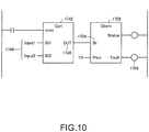
- FIG. 10 is a diagram schematically illustrating an example of the monitoring processing program that is executed by the control device 100 according to the embodiment.
- the feature quantity generation program 174 that is executed in the feature quantity generation step (3) included in the monitoring process in the control device 100 is described using the feature quantity generation function block 1742, as in FIG. 8 described above.
- a functional block 1702 is connected to the output stage (the output destination designation 1746) of the feature quantity generation function block 1742 in FIG. 10 .
- the output destination designation 1746 of the feature quantity generation function block 1742 is connected to the input variable designation 1704 for designating a variable serving as a feature quantity of a monitoring target of the functional block 1702.
- a variable value TH hereinafter, also referred to as a threshold value TH
- the functional block 1702 corresponds to a functional module of the abnormality detection engine 140.
- the functional block 1702 compares, in each control cycle, the variable (the feature quantity) designated in the input variable designation 1704 with the threshold value TH corresponding to the threshold value 304 designated in the abnormality detection parameter 136, and sets a variable (the score value 147) defined as the abnormality detection output destination designation 1708 when an event in which the feature quantity crosses the threshold value TH occurs.
- a variable the score value 147 defined as the abnormality detection output destination designation 1708 when an event in which the feature quantity crosses the threshold value TH occurs.
- the score value 147 can include, for example, a degree of separation of the feature quantity from the class of the learning data 134, such as a distance of the feature quantity from the reference position (see the mark x in FIG. 9 ) of the class of the learning data 134 or a distance between the feature quantity and the threshold value TH.
- a score value 147 may indicate a degree of classification into a class consisting of the learning data 134 in a normal state and a class consisting of the learning data 134 in an abnormal state.
- the monitoring processing program (that is, the feature quantity generation program 174 and the function block of the abnormality detection engine 140) of the control device 100 illustrated in FIG. 10 described above corresponds to a program that is emulated by the monitoring processing emulator 2272 of the support device 200. Therefore, the support device 200 executes the emulation in the monitoring processing emulator 2272 using the time-series raw data 132 received from the control device 100, and therefore, the control device 100 can reproduce the monitoring process performed using the raw data 132 collected in the raw data collection step (1) (see FIG. 5 ).
- FIG. 11 is a schematic diagram illustrating the evaluation step and adjustment step according to the embodiment.
- the evaluation unit 2270 evaluates validity (suitability) indicating whether or not the abnormality detection parameter 136 or the learning data 134 held in the control device 100 is suitable for detection of an abnormality occurring in the control target.
- the evaluation process will be described with reference to FIG. 11 .
- a monitoring process is performed using the feature quantity that is generated from the raw data 132 of FIG. 11(A) , the abnormality detection parameter 136, and the learning data 134. Since the score value 147 that is output in the monitoring process crosses a threshold value TH as illustrated in FIG. 11(B) , an event log 146 of "abnormality" is obtained as illustrated in FIG. 11(C) .
- the evaluation unit 2270 evaluates the validity indicating whether the abnormality detection parameter 136 held in the control device 100 is suitable for detection of an abnormality occurring in the control target. For example, a case in which the event log 146 indicates an abnormality, but an operator determines that the control target is normal (there is no abnormality) when observing the control target will be described.
- the evaluation unit 2270 extracts the raw data 132 (a portion indicated by a dashed line in FIG. 11(D) ) of a time corresponding to a time when "abnormality" has been recorded in the event log 146 from the time-series raw data 132 (a portion indicated by a dashed line in FIG. 11(D) ) acquired from the control device 100.
- the evaluation unit 2270 causes the monitoring processing emulator 2272 to execute emulation of the monitoring process using the extracted raw data 132, the abnormality detection parameter 136 of the internal DB 224, and the learning data 134. A result of this emulation indicates that there is an abnormality as illustrated in FIGS. 11(B) and (D) .
- the evaluation unit 2270 outputs an evaluation that the abnormality detection parameter 136 is not valid from the result of emulating this monitoring process.
- the adjustment unit 2271 changes the threshold value 304 illustrated in FIG. 9 according to a user operation. Accordingly, the threshold value 304 included as the abnormality detection parameter 136 of the internal DB 224 is changed.
- the evaluation unit 2270 causes the monitoring processing emulator 2272 to execute the emulation of the monitoring process again using the abnormality detection parameter 136 having the extracted raw data 132 (a portion indicated by a dashed line in FIG. 11(D) ) and the threshold value 304 after changing of the internal DB 224 and the learning data 134.
- the evaluation unit 2270 outputs an evaluation that the abnormality detection parameter 136 after the adjustment (change) is valid from a result of emulating the monitoring process of the monitoring processing emulator 2272.
- the evaluation unit 2270 evaluates that the abnormality detection parameter 136 after the adjustment (change) is not valid from a result of emulating the monitoring process when the emulation of the monitoring process has been executed again in the monitoring processing emulator 2272, the processes of the adjustment unit 2271 and the evaluation unit 2270 are repeated.
- An adjustment method of the adjustment unit 2271 is not limited to changing of the threshold value 304.
- the learning data 134 the feature quantity space of FIG. 9
- the evaluation process of the evaluation unit 2270 including the emulation of the monitoring process of the monitoring processing emulator 2272 may be executed again.
- the user transfers the abnormality detection parameter 136 or the learning data 134 after adjustment has ended, to the control device 100 via the memory card 116. Accordingly, the control device 100 can update the original abnormality detection parameter 136 or learning data 134 held in the internal DB 130 using the abnormality detection parameter 136 or the learning data 134 after the adjustment (that is, having validity).
- control device 100 can also perform additional learning on the learning data 134.
- the control device 100 holds a class of the feature quantity (learning data 134) suitable for detection of an abnormality occurring in the control target, and the control device 100 updates the feature quantity included in the class using the feature quantity that is generated by the feature quantity generation program 174 during execution of the monitoring process. For example, using a feature quantity extracted from the generated feature quantity, the feature quantity is added to the learning data 134.
- the feature quantity of the raw data 132 collected at the time of an operation of the production line in the control device 100 is added, and therefore, the learning data 134 changes.
- the evaluation unit 2270 may perform the evaluation process using the learning data 134 after the change. Based on a result of the evaluation process, the adjustment unit 2271 adjusts the abnormality detection parameter 136 or the learning data 134. Accordingly, the learning data 134 can be generated by the control device 100, and validity thereof can be evaluated by the evaluation unit 2270 of the support device 200.
- FIG. 12 is a schematic diagram illustrating execution of a process according to a priority in the control device 100 according to the embodiment.
- the control computation includes control computation that is performed by executing the sequence/motion program 162.
- the control computation includes, for example, sequence computation for executing a process according to various conditions, and motion computation for driving a servo driver or a servo motor.
- Such control computation is typically provided by the processor 102 of the control device 100 reading the user program stored in the secondary storage device 108, opening the user program in the main storage device 106, and executing the user program. That is, the processor 102 of the control device 100 and the user program provide a control computation process for cyclically executing control computation for controlling the control target.
- a process which is necessarily executed in each system cycle (for example, the I/O refresh process and the control computation) is registered as the high priority task, and a process that may be executed over a plurality of system cycles or a process for which an execution timing need not be strictly guaranteed (for example, the monitoring process) is registered as the low priority task.
- the monitoring process registered as the low priority task is executed.
- the low priority task is executed in a period in which the high priority task is not being executed in each system cycle. Therefore, a process registered as the low priority task cannot be completed in one system cycle in some cases.
- the monitoring process is executed over three system cycles. It should be noted that, for example, when the control device 100 includes a plurality of processors 102 or when the processor 102 of the control device 100 includes a plurality of cores, each task may be executed in a distributed manner.
- an execution management unit that executes the collection (the I/O refreshing process) of the raw data 132 of the variable manager 154 (the collection unit) and the control computation (the sequence/motion program 162) of the computation processing unit with a higher priority than the monitoring process (the feature quantity generation program 174 and the abnormality detection engine 140) of the monitoring processing unit is realized by the scheduler 152.
- execution management according to the priority of the scheduler 152 is emulated by the scheduler emulator 2269 in the PLC emulator 2260.
- emulation is executed by a system program emulator 2267 that emulates collection (an I/O refresh process) of the raw data 132 that is performed by the variable manager 154 (a collection unit) and control computation (a sequence/motion program 162) of the computation processing unit, and the monitoring processing emulator 2272 that emulates the monitoring process.
- the evaluation unit 2270 evaluates the validity from a scheduling result according to the emulation of the scheduler emulator 2269.
- the evaluation unit 2270 outputs an evaluation that the abnormality detection parameter 136 is not valid.
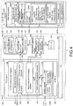
- FIG. 4 numbers in parentheses in a configuration of the control device 100 correspond to the processes in steps (1) to (6) illustrated in FIG. 5 . Further, in FIG. 4 , numbers in parentheses in a configuration of the support device 200 correspond to the processes in steps (1) to (7) illustrated in FIG. 6 .
- the control device 100 includes the PLC engine 150, in addition to the internal DB 130 and the abnormality detection engine 140. These functions are basically realized by the processor 102 ( FIG. 2 ) of the control device 100 executing a program. In order to provide an environment in which the processor 102 executes the program, an OS 190 is also installed in the control device 100.
- the PLC engine 150 is typically provided by executing a system program and a user program on the OS 190. More specifically, the PLC engine 150 includes the scheduler 152, the variable manager 154, and the control program 160.
- the scheduler 152 controls an execution timing, an execution order, and the like of each program (or a task corresponding to the program) constituting the PLC engine 150.
- an execution cycle is determined in advance for each task included in the PLC engine 150 corresponding to the execution management unit that executes the process according to the priority described above.
- the scheduler 152 performs control so that the program can be repeatedly executed according to the determined execution cycle and the priority.
- the variable manager 154 manages, as a variable, data that is updated through the I/O refresh process that is cyclically executed in the PLC engine 150. More specifically, the variable manager 154 holds and manages a system variable 1542 including a data group indicating an operation state of each unit of the control device 100, and a user variable and device variable 1544 including a data group that is written or read by the user program that is executed by the PLC engine 150.
- data associated with the control target mainly includes data that can be collected as the user variable and device variable 1544.
- the control program 160 corresponds to a user program that the user can arbitrarily create, and typically includes a sequence/motion program 162, an internal DB access program 164, an abnormality detection engine interface 166, and a feature quantity generation program 174. Instructions of a program constituting the control program 160 may be described as an integrated program or may be described as a plurality of separate programs.
- the sequence/motion program 162 includes an instruction for performing logical computation and/or numerical computation for controlling the control target.
- the internal DB access program 164 writes data of a variable designated in advance among variables included in the user variable and device variable 1544 to the internal DB 130.
- the time-series DB program 163 writes data to be written to the time-series DB 131 with a time stamp.
- the internal DB access program 164 writes, for example, the learning data 134 and the abnormality detection parameter 136 read from the storage medium such as the memory card 116 by the drive 204 to the internal DB 130.
- the internal DB access program 164 reads data such as the raw data 132, the learning data 134, and the score value 147 in the time-series DB 131 of the internal DB 130, and writes the read data to the storage medium such as the memory card 116 via the drive 204.
- the memory card 116 can be used as a storage medium for exchanging data between the control device 100 and the support device 200. It should be noted that the storage medium for data exchange is not limited to the memory card 116, and may be, for example, a USB memory.
- the abnormality detection engine interface 166 includes an instruction for operating the abnormality detection engine 140. Specifically, the abnormality detection engine interface 166 includes an instruction to instruct the abnormality detection engine 140 to extract the feature quantity using the abnormality detection parameter 136, and an instruction to instruct the abnormality detection engine 140 to monitor the feature quantity using the abnormality detection parameter 136 and detect an abnormality.
- the feature quantity generation program 174 includes an instruction to generate a feature quantity using a designated variable of the user variable and device variable 1544 according to a previously specified feature quantity generation scheme.
- An appropriate feature quantity generation scheme is determined according to the control target by the support device 200. That is, the feature quantity generation program 174 generates a feature quantity suitable for detection of an abnormality occurring in the control target from the data related to the control target.
- the raw data 132 collected in the raw data collection step (1) of FIG. 5 , the learning data 134 and the abnormality detection parameters 136 input from the support device 200, and the score value 147 output in the abnormality detection step (5) of FIG. 5 are stored in the internal DB 130.
- a part of the internal DB 130 constitutes the time-series DB 131 by the raw data 132 being time-stamped in an order of collection (detection) in the time-series DB storage step (2) of FIG. 5 and stored.
- the abnormality detection engine 140 includes the feature quantity extraction unit 142 for executing a process necessary in the feature quantity extraction step (4) and the abnormality detection unit 144 for executing a process necessary in the abnormality detection step (5) in FIG. 5 .
- the feature quantity extraction unit 142 extracts a feature quantity of a type indicated by the abnormality detection parameter 136 from the feature quantity that is generated through execution of the feature quantity generation program 174.
- the abnormality detection unit 144 detects an abnormality in the control target using the feature quantity extracted by the feature quantity extraction unit 142 and the abnormality detection parameter 136. When the abnormality detection unit 144 detects any abnormality, the abnormality detection unit 144 outputs the score value 147 and outputs the event log 146 indicating the detected content.
- the data mining tool 226 is a tool for generating the abnormality detection parameter 136 and the learning data 134 suitable for detection of an abnormality occurring in the control target based on the raw data related to the control target collected by the control device 100 including the feature quantity generation program 174 and the abnormality detection engine 140.
- the generation of the abnormality detection parameter 136 and the learning data 134 can include a concept of a determination and adjustment (change) of the abnormality detection parameter 136 and the learning data 134.
- the data mining tool 226 includes a data access unit 2262, a determination unit 2264, a PLC emulator 2260, and the evaluation unit 2270 and the adjustment unit 2271 described above.
- the PLC emulator 2260 is mainly provided as a program, and the other units are provided to include a program or a circuit (ASIC, FPGA, or the like).
- the data access unit 2262 includes a module that is used for the support device 200 to exchange data with the control device 100. Specifically, the data access unit 2262 stores, in the internal DB 224, the time-series raw data 132, the score value 147, and the event log 146 read from the storage medium such as the memory card 116 via the drive 204, and the data access unit 2262 reads the abnormality detection parameter 136, the learning data 134, and the like determined (adjusted) by the support device 200 from the internal DB 224, and stores the abnormality detection parameter 136, the learning data 134, and the like in the memory card 116 via the drive 204.
- the raw data collection step (1) in FIG. 6 is realized by the data access unit 2262.
- the determination unit 2264 corresponds to a machine learning engine, and includes a learning data determination unit 2261 that generates (determines) the learning data 134 by performing machine learning, and a parameter determination unit 2263 that determines the abnormality detection parameter 136.
- the support device 200 includes an emulator that emulates a process (program) that is executed by the control device 100 on a processor (computer) of the support device 200.
- the emulator included in the support device 200 is realized by the PLC emulator 2260 that emulates the PLC engine 150.
- the PLC emulator 2260 includes a control program emulator 2265 that emulates a control program 160, a system program emulator 2267 that emulates a system program of the control device 100, and a scheduler emulator 2269 that emulates the scheduler 152.
- the control program emulator 2265 includes a monitoring processing emulator 2272 that emulates the monitoring process, and the system program emulator 2267 includes a variable manager emulator 2268 that emulates the variable manager 154.
- the monitoring processing emulator 2272 includes an emulator that emulates the abnormality detection engine 140, and a feature quantity generation program emulator 2266 that emulates the feature quantity generation program 174.
- the data mining step (2) in FIG. 6 is realized by the data mining tool 226. Further, the feature quantity collection step (3) is realized by the feature quantity generation program emulator 2266 emulating the feature quantity generation program 174 using the time-series raw data 132 in the internal DB 224.
- the PLC emulator 2260 reproduces the process of monitoring the state of the control target in the "monitoring processing unit" of the control device 100.
- the support device 200 includes the evaluation unit 2270 that evaluates the validity of the abnormality detection parameter 136 or the learning data 134 held by the control device 100 as described above, and an adjustment unit 2271 for adjusting (changing) the abnormality detection parameter 136 or the learning data 134 held by the control device 100.
- the learning data 134 is generated by the support device 200 and set in the control device 100 in the embodiment, the learning data 134 may be given data. In addition, the learning data 134 may be generated from the feature quantity when the control target is in an abnormal state or may be generated from the feature quantity when the control target is in the normal state.
- the feature quantity from the time-series raw data 132 is generated by executing the feature quantity generation program emulator 2266, but a generation method is not limited to the method using the emulator.
- the support device 200 may generate the feature quantity by executing a program having the same function as the feature quantity generation program 174 of the control device 100.
- a control system (1) including:
- control device further includes a database (131) that stores the data (132) associated with the control target collected by the collection unit in time series, and the data associated with the control target that is used by the monitoring emulator of the information processing device includes data in the database of the control device.
- control system according to configuration 1 or 2, wherein the information processing device further includes a unit (2270) that evaluates validity indicating whether the abnormality detection parameter held in the control device is suitable for detection of the abnormality occurring in the control target based on a result of the emulation of the monitoring process.
- a unit (2270) that evaluates validity indicating whether the abnormality detection parameter held in the control device is suitable for detection of the abnormality occurring in the control target based on a result of the emulation of the monitoring process.
- control device further includes an execution management unit (152) that cyclically executes collection of data of the collection unit and control computation of the computation processing unit and executes a cyclic execution process for causing collection of data of the collection unit and control computation of the computation processing unit to be executed with a higher priority than the monitoring process of the monitoring processing unit in the cyclic execution
- the information processing device includes a cyclic execution emulator (2269) that emulates the cyclic execution process of the execution management unit, and emulation of a monitoring process of the monitoring emulator is executed in the emulation of the cyclic execution process of the cyclic execution emulator.
- the information processing device further includes a unit that evaluates validity indicating whether or not the abnormality detection parameter that is held in the control device is suitable for detection of an abnormality occurring in the control target, based on a result of the emulation of the cyclic execution process.
- control device further includes a database (131) that stores the data associated with the control target collected by the collection unit in time series
- the information processing device further includes a time-series feature quantity generation unit that generates a feature quantity from time-series data of the data associated with the control target in the database of the control device, and a determination unit (2264) that determines an abnormality detection parameter suitable for detection of an abnormality occurring in the control target by performing machine learning using the feature quantity generated by the time-series feature quantity generation unit.
- the monitoring emulator includes a feature quantity generation emulator (2266) that executes emulation of a feature quantity generation process of the feature quantity generation unit
- the time-series feature quantity generation unit includes a unit that causes the feature quantity generation emulator to execute emulation of the feature quantity generation process using the time-series data in the database to generate a feature quantity from the time-series data.
- the abnormality detection parameter suitable for detection of the abnormality occurring in the control target includes a threshold value (TH, 304) for classifying the feature quantity generated by the feature quantity generation unit into a class of feature quantities suitable for detection of the abnormality occurring in the control target.
- control device holds a class (134) of the feature quantity suitable for detection of the abnormality occurring in the control target, and the control device updates the feature quantity of the class using the feature quantity that is generated by the feature quantity generation unit during execution of the monitoring process.
- a control method that is executed by an information processing device (200) capable of exchanging data with a control device (100) that controls a control target
- the control device includes a computation processing unit (162) that executes control computation of sequence control and motion control related to the control target, a collection unit (154) that executes a process of collecting data associated with the control target, and a monitoring processing unit (174, 140) that executes a process of monitoring a state of the control target
- the monitoring processing unit includes a feature quantity generation unit (174) that executes a feature quantity generation process for generating a feature quantity from the data collected by the collection unit; and a detection unit (140) that executes an abnormality detection process for detecting an abnormality occurring in the control target using the feature quantity generated by the feature quantity generation unit and an abnormality detection parameter (136) suitable for detection of an abnormality occurring in the control target that is set based on a result of machine learning
- the control method comprises receiving the data associated with the control target from the control device; and executing emulation of the monitoring process of the monitoring
Abstract
Description
- The present disclosure relates to a control system and a control method for controlling a control target.
- In various production sites, factory automation (FA) technology using a control device such as a programmable logic controller (PLC) is widely used. With recent developments in information and communication technology (ICT), such a control device in the field of FA also has increasingly high performance and advanced functions.
- As one example of such high performance and advanced functions, a function of predicting failure of a device that is a control target using machine learning has been proposed. For example,
Patent Document 1 discloses a server including a machine learning device. The server including the machine learning device detects the presence or absence of failure or a degree of failure of a current device by executing machine learning using input data such as an output of a sensor provided in the device, which is received via a network. - Japanese Patent Application Laid-Open No.
2017-211930 - In a case where a server is used as in
Patent Document 1, reliability of machine learning in a server is degraded when loss of data, lack of data, or the like occurs due to, for example, an error during communication with the server. Therefore, a technique for performing abnormality detection using reliable machine learning on a control device side such as a PLC instead of causing the server to perform the machine learning is desired. - An objective of this disclosure is to provide an environment in which abnormality detection can be performed using reliable machine learning by a control device.
- A control system according to an example of the present disclosure is a control system including a control device that controls a control target; and an information processing device capable of exchanging data with the control device, wherein the control device includes a computation processing unit that executes control computation of sequence control and motion control related to the control target; a collection unit that executes a process of collecting data associated with the control target; and a monitoring processing unit that executes a process of monitoring a state of the control target, the monitoring processing unit includes a feature quantity generation unit that executes a feature quantity generation process for generating a feature quantity from the data collected by the collection unit; and a detection unit that executes an abnormality detection process for detecting an abnormality occurring in the control target using the feature quantity generated by the feature quantity generation unit and an abnormality detection parameter suitable for detection of an abnormality occurring in the control target that is set based on a result of machine learning, and the information processing device includes a monitoring emulator that executes emulation of the monitoring process of the monitoring processing unit using the data associated with the control target from the control device.
- According to the above-described disclosure, in the information processing device, the monitoring process of the monitoring processing unit of the control device can be emulated by the monitoring processing emulator and the monitoring process of the monitoring processing unit of the control device can be reproduced in the information processing device. Therefore, it is possible to provide content of the reproduction as information for confirming whether or not abnormality detection based on reliable machine learning can be performed inside the control device.
- According to an embodiment of the disclosure, the control device further includes a database that stores the data associated with the control target collected by the collection unit in time series, and the data associated with the control target that is used by the monitoring emulator of the information processing device includes data in the database of the control device.
- According to the above disclosure, the information processing device can reproduce the monitoring process of the monitoring processing unit of the control device retroactively by performing emulation of the monitoring emulator using the time-series data stored (accumulated) in time series.
- According to an embodiment of the disclosure, the information processing device evaluates validity indicating whether or not the abnormality detection parameter held in the control device is suitable for detection of the abnormality occurring in the control target based on a result of the emulation of the monitoring process.
- According to the above disclosure, it is possible to evaluate validity indicating whether or not the abnormality detection parameter is suitable for detection of an abnormality occurring in a control target.
- According to an embodiment of the disclosure, the control device further includes an execution management unit that cyclically executes collection of data of the collection unit and control computation of the computation processing unit and executes a cyclic execution process for causing collection of data of the collection unit and control computation of the computation processing unit to be executed with a higher priority than the monitoring process of the monitoring processing unit in the cyclic execution, wherein the information processing device includes a cyclic execution emulator that emulates the cyclic execution process of the execution management unit, and emulation of a monitoring process of the monitoring emulator is executed in the emulation of the cyclic execution process of the cyclic execution emulator.
- According to the above disclosure, regarding the evaluation of the validity of the abnormality detection parameter, the information processing device can emulate the cyclic (periodical) execution of the control computation of the control device and evaluate the validity based on a result of the emulation of the monitoring process of the monitoring emulator in the cyclic execution.
- According to an embodiment of the disclosure, the information processing device evaluates validity indicating whether or not the abnormality detection parameter that is held in the control device is suitable for detection of an abnormality occurring in the control target, based on a result of the emulation of the cyclic execution process.
- According to the above disclosure, it is possible to evaluate the validity of the abnormality detection parameter based on the result of the emulation of the cyclic execution process.
- According to an embodiment of the disclosure, the evaluation of the validity based on the result of the emulation of the cyclic execution process includes evaluation of the validity based on a result of a comparison between a time taken for emulation of the monitoring process in the emulation of the cyclic execution process and a length of the cycle.
- According to the above disclosure, it is possible to perform evaluation of the validity from the time taken for emulation of the monitoring processing in the emulation of the cyclic execution process.
- According to an embodiment of the disclosure, the control device further includes a database that stores the data associated with the control target collected by the collection unit in time series, and the information processing device further includes a time-series feature quantity generation unit that generates a feature quantity from time-series data of the data associated with the control target in the database of the control device, and a determination unit that determines an abnormality detection parameter suitable for detection of an abnormality occurring in the control target by performing machine learning using the feature quantity generated by the time-series feature quantity generation unit.
- According to the above disclosure, the information processing device can generate the feature quantity from the time-series data of the data associated with the control target in the database of the control device, and determine an abnormality detection parameter suitable for detection of an abnormality occurring in the control target from the learning result of the machine learning using the generated feature quantity.
- According to an embodiment of the disclosure, the monitoring emulator includes a feature quantity generation emulator that executes emulation of a feature quantity generation process of the feature quantity generation unit, and the time-series feature quantity generation unit includes a unit that causes the feature quantity generation emulator to execute emulation of the feature quantity generation process using the time-series data in the database to generate a feature quantity from the time-series data.
- According to the above disclosure, the information processing device causes the feature quantity generation emulator to execute emulation of the feature quantity generation process, such that the feature quantity can be generated from the time-series data.
- According to an embodiment of the disclosure, the abnormality detection parameter suitable for detection of the abnormality occurring in the control target includes a threshold value for classifying the feature quantity generated by the feature quantity generation unit into a class of feature quantities suitable for detection of the abnormality occurring in the control target.
- According to the above disclosure, the threshold value for classifying the feature quantities into classes can be included in the abnormality detection parameter.
- According to an embodiment of the disclosure, the control device holds a class of the feature quantity suitable for detection of the abnormality occurring in the control target, and the control device updates the feature quantity of the class using the feature quantity that is generated by the feature quantity generation unit during execution of the monitoring process.
- In the above disclosure, the control device can update the feature quantity of the class using the feature quantity generated from the data collected from the control target, and the classification into classes using the updated class becomes possible.
- A control method according to an example of the present disclosure is a control method that is executed by an information processing device capable of exchanging data with a control device that controls a control target, wherein the control device includes a computation processing unit that executes control computation of sequence control and motion control related to the control target, a collection unit that executes a process of collecting data associated with the control target, and a monitoring processing unit that executes a process of monitoring a state of the control target, the monitoring processing unit includes a feature quantity generation unit that executes a feature quantity generation process for generating a feature quantity from the data collected by the collection unit; and a detection unit that executes an abnormality detection process for detecting an abnormality occurring in the control target using the feature quantity generated by the feature quantity generation unit and an abnormality detection parameter suitable for detection of an abnormality occurring in the control target that is set based on a result of machine learning, and the control method comprises receiving the data associated with the control target from the control device; and executing emulation of the monitoring process of the monitoring processing unit using the data associated with the control target received from the control device.
- According to the above disclosure, in the information processing device, the monitoring process of the monitoring processing unit of the control device can be emulated by the monitoring processing emulator and the monitoring process of the monitoring processing unit of the control device can be reproduced in the information processing device. Therefore, it is possible to provide content of the reproduction as information for confirming whether or not abnormality detection based on reliable machine learning can be performed inside the control device.
- According to this disclosure, it is possible to provide an environment in which a control device can perform abnormality detection using reliable machine learning.
-
-
FIG. 1 is a schematic diagram illustrating an overall configuration example of acontrol system 1 according to the embodiment. -
FIG. 2 is a block diagram illustrating an example of a hardware configuration of a control device constituting thecontrol system 1 according to the embodiment. -
FIG. 3 is a block diagram illustrating an example of a hardware configuration of a support device constituting thecontrol system 1 according to the embodiment. -
FIG. 4 is a schematic diagram illustrating an example of a situation in which thecontrol system 1 according to the embodiment is applied. -
FIG. 5 is a schematic diagram illustrating a procedure of abnormality detection using the control device according to the embodiment. -
FIG. 6 is a schematic diagram illustrating a data mining procedure in the support device according to the embodiment. -
FIG. 7 is a diagram schematically illustrating an example of a list showing feature quantities that can be determined in a data mining step of the control system according to the embodiment. -
FIG. 8 is a diagram schematically illustrating an example of a feature quantity generation program and a program of a learning data determination unit according to this embodiment. -
FIG. 9(A) and FIG. 9(B) are diagrams schematically illustrating an example of learning data according to the embodiment. -
FIG. 10 is a diagram schematically illustrating an example of a monitoring processing program that is executed by acontrol device 100 according to the embodiment. -
FIG. 11 is a schematic diagram illustrating an evaluation step and an adjustment step according to this embodiment. -
FIG. 12 is a schematic diagram illustrating execution of a process according to a priority in thecontrol device 100 according to the embodiment. - Embodiments of the present invention will be described in detail with reference to the drawings. In the figures, the same or corresponding units are denoted by the same reference numerals, and description thereof will not be repeated.
- First, an example of a situation in which the present invention is applied will be described with reference to
FIG. 4. FIG. 4 is a schematic diagram illustrating an example of a situation in which acontrol system 1 according to the embodiment is applied. In thecontrol system 1 according to the embodiment, thecontrol device 100 controls an arbitrary control target (for example, a manufacturing device or equipment included in a production line). -
FIG. 4 schematically illustrates functions that are provided by respective devices of thecontrol system 1. Thecontrol system 1 includes acontrol device 100 that controls a control target and asupport device 200 that can exchange data with thecontrol device 100. Thecontrol device 100 corresponds to an industrial controller such as a PLC that controls control targets such as various facilities or devices. The PLC is a type of computer that executes a control computation. Thesupport device 200 provides a user with, for example, an environment for developing a module (typically, data, programs, or the like) included in thecontrol device 100 or an environment for monitoring a state of thecontrol device 100. Thesupport device 200 includes an example of the "information processing device" and typically includes a general-purpose computer. - The
control device 100 includes a computation processing unit that executes control computation of sequence control and motion control related to a control target, a collection unit that executes a process of collecting data (raw data 132) associated with the control target, and a monitoring processing unit that executes a process of monitoring a state of the control target. - When the production line or the like is in operation, a
PLC engine 150 executes avariable manager 154 corresponding to a "collection unit" to collect data associated with the control target while executing a sequence/motion program 162 corresponding to the "control computation." Further, the "monitoring processing unit" includes a feature quantity generation unit that executes a feature quantity generation process of generating a feature quantity from the collected data, and anabnormality detection engine 140. - The feature quantity generation unit corresponds to a feature
quantity generation program 174, and the feature quantity generation process is executed by executing the featurequantity generation program 174. Theabnormality detection engine 140 executes an abnormality detection process of detecting an abnormality occurring in a control target using the feature quantity generated by the feature quantity generation unit and anabnormality detection parameter 136 or learningdata 134 suitable for detection of an abnormality held in aninternal DB 130. Theabnormality detection parameter 136 or the learningdata 134 is based on a learning result of machine learning of thesupport device 200. - The
support device 200 includes a monitoring processing emulator 2272 that executes emulation of the "monitoring processing unit" using the data associated with the control target from thecontrol device 100. The monitoring processing emulator 2272 executes an instruction to emulate the featurequantity generation program 174 and a program of theabnormality detection engine 140 in a processor environment that is provided by a computer of thesupport device 200. Accordingly, the "monitoring processing unit" of thecontrol device 100 is emulated in thesupport device 200. - Thus, in the
support device 200, the monitoring process of the "monitoring processing unit" of thecontrol device 100 can be emulated by the monitoring processing emulator 2272 and the monitoring process of the "monitoring processing unit" of thecontrol device 100 can be reproduced in thesupport device 200. Therefore, it is possible to provide content of the reproduction as information for confirming whether or not reliable machine learning can be performed inside thecontrol device 100. - The "collection unit" of the
control device 100 corresponds to thevariable manager 154. Thevariable manager 154 collects data of a user variable and device variable 1544 that is updated by an I/O refresh process that is cyclically executed, in synchronization with the cycle. The collected data is used for the above monitoring process and is stored as time-seriesraw data 132 in an order of collection (detection) in a time-series DB 131. A time-series DB program 163 adds a time stamp to theraw data 132 collected by the collection unit in the order of collection (detection), and stores the resultant raw data in the time-series DB 131. This time stamp can be assigned in units of time that can be variably set, such as units of control cycles, units of works, or units of takt time. - Regarding the above reproducibility, the data associated with the control target that is used by the monitoring processing emulator 2272 of the
support device 200 includes the time-seriesraw data 132 in the time-series DB 131 of thecontrol device 100. Thus, the emulation in thesupport device 200 is performed using the time-seriesraw data 132 in the time-series DB 131. - Therefore, by performing emulation using the time-series data stored (accumulated) in time series, the
support device 200 can reproduce the monitoring process of the "monitoring processing unit" of thecontrol device 100 retroactively. - Regarding the above reproduction, the
support device 200 is capable of exchanging data including the time-seriesraw data 132 in the time-series DB 131 with thecontrol device 100. In this case, for example, adata access unit 2262 of thesupport device 200 can exchange data with thecontrol device 100 via a storage medium such as a memory card in which theraw data 132 has been stored. - By exchanging such data via the storage medium instead of passing through the network, the
support device 200 can receive the time-seriesraw data 132 in the time-series DB 131 without causing data loss due to a communication error. Therefore, in thesupport device 200, it is possible to improve accuracy of the reproducibility using the emulation. - It should be noted that the exchange of data between the
support device 200 and thecontrol device 100 is not limited to a method in which the exchange is via the storage medium. - The
support device 200 further includes anevaluation unit 2270 that evaluates validity indicating whether or not theabnormality detection parameter 136 held in thecontrol device 100 is suitable for detection of an abnormality occurring in the control target based on a result of the emulation of the monitoring process. - Regarding such evaluation of the validity of the
abnormality detection parameter 136, thesupport device 200 emulates cyclic execution of the control computation of thecontrol device 100 and evaluates the validity based on a result of the emulation. - Regarding the cyclic execution of the control computation, the
control device 100 cyclically executes the collection (the variable manager 154) of the data associated with the control target and control computation (the sequence/motion program 162) according to a computation process. In this cyclic execution, thecontrol device 100 further includes an execution management unit (a scheduler 152) that executes a cyclic execution process for executing the collection of the data associated with the control target and the control computation according to the computation process with a higher priority than the "monitoring process" (the featurequantity generation program 174 and the abnormality detection engine 140). - Regarding the emulation of the cyclic execution, the
support device 200 includes aPLC emulator 2260 that emulates thePLC engine 150. ThePLC emulator 2260 includes a cyclic execution emulator (a scheduler emulator 2269) that emulates the cycle execution process of the execution management unit (the scheduler 152). In the emulation of the cyclic execution process of the cyclic execution emulator, emulation of a control program emulator 2265 (a monitoring processing emulator 2272 including a feature quantity generation program emulator 2266) and asystem program emulator 2267 including a variable manager emulator 2268, which are included in thePLC emulator 2260, is executed. - Thus, the
support device 200 can evaluate the validity of theabnormality detection parameter 136 based on an execution result (content of reproduction) of the emulation of the monitoring process in the emulation of the cyclic execution of the control computation of thecontrol device 100. - For example, when the
evaluation unit 2270 evaluates the validity based on the result of the emulation of the cyclic execution process, theevaluation unit 2270 can evaluate the validity based on a result of comparison of a time taken for the emulation of the monitoring process in the emulation of the cyclic execution process with a length of a cycle of the cyclic execution. - Hereinafter, a more detailed configuration and a process of the
control system 1 according to the embodiment will be described as a more specific application example of the present disclosure. - First, an overall configuration example of the
control system 1 according to the embodiment will be described. -
FIG. 1 is a schematic diagram illustrating an example of the overall configuration of acontrol system 1 according to the embodiment. Referring toFIG. 1 , thecontrol system 1 according to the embodiment includes acontrol device 100 that controls a control target, and asupport device 200 that can be connected to controldevice 100, as main components. Thesupport device 200 exchanges data with thecontrol device 100 through communication or a storage medium. - The
control device 100 may be embodied as a type of computer such as a programmable logic controller (PLC). Thecontrol device 100 is connected to afield device group 10 via afirst field network 2 and to one or a plurality ofdisplay devices 400 via asecond field network 4. Further, thecontrol device 100 is connected to adata logging device 600 via alocal network 6. Thecontrol device 100 exchanges data with the connected devices via the respective networks. It should be noted that thedata logging device 600 and thedisplay devices 400 are optional configurations and are not indispensable components of thecontrol system 1. - The
control device 100 includes a control logic (hereinafter also referred to as a "PLC engine") that executes various computations for controlling a facility or machine. In addition to the PLC engine, thecontrol device 100 also has a collection function of collecting data (hereinafter also referred to as "input data") measured by thefield device group 10 and transferred to the control device 100). Further, thecontrol device 100 also has a monitoring function of monitoring the collected input data. By causing thecontrol device 100 to have these functions, it is possible to monitor a phenomenon occurring in the control target at shorter cycles. - Specifically, an internal database (hereinafter, also referred to as an "internal DB") 130 mounted in the
control device 100 provides the collection function, and theabnormality detection engine 140 mounted in thecontrol device 100 provides the monitoring function. Details of theinternal DB 130 and theabnormality detection engine 140 will be described later. - It is preferable for a network that performs cyclic communication in which an arrival time of data is guaranteed to be adopted for the
first field network 2 and thesecond field network 4. EtherCAT (registered trademark), EtherNet/IP (registered trademark), DeviceNet (registered trademark), CompoNet (registered trademark), and the like are known as networks that perform such cyclic communication. - The
field device group 10 includes a device that collects input data from the control target or a manufacturing device, a production line, or the like related to control (hereinafter also referred to as a "field"). An input relay, various sensors, or the like are assumed as such a device that collects input data. Thefield device group 10 further includes a device that gives some actions to the field based on a command (hereinafter also referred to as "output data") generated by thecontrol device 100. An output relay, a contactor, a servo driver, a servo motor, and another arbitrary actuator are assumed as such a device that gives some actions to the field. Thefield device group 10 exchanges data including the input data and the output data with thecontrol device 100 via thefirst field network 2. - In the example of the configuration illustrated in
FIG. 1 , thefield device group 10 includes a remote input/output (I/O)device 12, arelay group 14, animage sensor 18, acamera 20, aservo driver 22, and aservo motor 24. - The remote I/
O device 12 includes a communication unit that performs communication via thefirst field network 2, and an input/output unit (hereinafter referred to as an "I/O unit") for performing acquisition of input data and output of output data. The input data and the output data are exchanged between thecontrol device 100 and the field via such an I/O unit. An example in which digital signals are exchanged as input data and output data via therelay group 14 is illustrated inFIG. 1 . - The I/O unit may be directly connected to the field network. An example in which the I/
O unit 16 is directly connected to thefirst field network 2 is illustrated inFIG. 1 . - The
image sensor 18 performs an image measurement process such as pattern matching on image data captured by thecamera 20 and transmits a result of the process to thecontrol device 100. - The
servo driver 22 drives theservo motor 24 according to output data (for example, a position command) from thecontrol device 100. - As described above, data is exchanged between the
control device 100 and thefield device group 10 via thefirst field network 2, but these exchanged pieces of data are updated in a very short cycle on the order of hundreds of µsec to tens of msec. It should be noted that this process of updating the exchanged data may be referred to as an "I/O refresh process." - In addition, the
display device 400 connected to thecontrol device 100 via thesecond field network 4 transmits, for example, a command according to a user operation to thecontrol device 100 in response to an operation from the user, and graphically displays, for example, a result of computation in thecontrol device 100. - The
data logging device 600 is connected to thecontrol device 100 via thelocal network 6, and exchanges necessary data with thecontrol device 100. Thedata logging device 600 has, for example, a database function, and collects, for example, event logs that are generated by thecontrol device 100, in a time-series. A general-purpose protocol such as Ethernet (registered trademark) may be mounted on thelocal network 6. That is, typically, a transmission cycle or an updating cycle of data in thelocal network 6 may be later than a transmission cycle or an updating cycle of data in the field network (thefirst field network 2 and the second field network 4). However, thelocal network 6 may be able to transmit more data at the same time than the field network. - The
support device 200 is a device that supports preparation necessary for thecontrol device 100 to control the control target. Specifically, thesupport device 200 provides, for example, a program development environment (a program creation and editing tool, a parser, a compiler, or the like) for a program that is executed by thecontrol device 100, a setting environment for setting parameters (configuration) of thecontrol device 100 and various devices connected to thecontrol device 100, a function of transmitting a generated user program to thecontrol device 100, and a function of correcting and changing, online, the user program or the like that is executed on thecontrol device 100. - Further, the
support device 200 according to the embodiment determines, for example, theabnormality detection parameter 136 using the time-seriesraw data 132, to be described later, of theinternal DB 130 mounted in thecontrol device 100, and also provides an environment in which theabnormality detection engine 140 is emulated. Details of this emulation will be described later. - Next, an example of a hardware configuration of main devices constituting the
control system 1 according to the embodiment will be described. -
FIG. 2 is a block diagram illustrating an example of a hardware configuration of thecontrol device 100 constituting thecontrol system 1 according to the embodiment. Referring toFIG. 2 , thecontrol device 100 includes, for example, aprocessor 102 such as central processing unit (CPU) or a micro-processing unit (MPU), achipset 104, amain storage device 106, asecondary storage device 108, alocal network controller 110, a Universal Serial Bus (USB)controller 112, amemory card interface 114, aninternal bus controller 122,field bus controllers - The
processor 102 reads various programs stored in thesecondary storage device 108, develops the programs in themain storage device 106, and executes the programs, thereby realizing control according to the control target and various processes to be described later. Thechipset 104 realizes a process of theentire control device 100 by controlling theprocessor 102 and each component. - The
secondary storage device 108 stores a user program to be executed using the PLC engine, in addition to a system program for realizing the PLC engine. Further, a program for realizing theinternal DB 130 and theabnormality detection engine 140 is also stored in thesecondary storage device 108. - The
local network controller 110 controls exchange of data with other devices via thelocal network 6. TheUSB controller 112 controls exchange of data with thesupport device 200 via a USB connection. - The
memory card interface 114 is configured such that amemory card 116 can be attached and detached, and data can be written to thememory card 116 and various pieces of data (a user program, trace data, or the like) can be read from thememory card 116. - The
internal bus controller 122 is an interface that exchanges data with the I/O units 124-1, 124-2, ... mounted in thecontrol device 100. - The
field bus controller 118 controls exchange of data with other devices via thefirst field network 2. Similarly, thefield bus controller 120 controls exchange of data with other devices via thesecond field network 4. - Although an example of a configuration in which the necessary functions are provided by the
processor 102 executing the program has been illustrated inFIG. 2 , some or all of the provided functions may be implemented using a dedicated hardware circuit (for example, an application specific integrated circuit (ASIC), a field-programmable gate array (FPGA), or the like). Alternatively, main units of thecontrol device 100 may be realized using hardware conforming to a general-purpose architecture (for example, an industrial personal computer based on a general-purpose personal computer). In this case, a plurality of operating systems (OSs) having different uses may be executed in parallel using a virtualization technique and necessary applications may be executed on each OS. - Next, the
support device 200 according to the embodiment is realized, for example, by executing a program using hardware (for example, a general-purpose personal computer) conforming to a general-purpose architecture. -
FIG. 3 is a block diagram illustrating an example of a hardware configuration of thesupport device 200 constituting thecontrol system 1 according to the embodiment. Referring toFIG. 3 , thesupport device 200 includes aprocessor 202 such as a CPU or an MPU, adrive 204, amain storage device 206, asecondary storage device 208, aUSB controller 212, alocal network controller 214, aninput unit 216, and adisplay unit 218. These components are connected via abus 220. - The
processor 202 reads various programs stored in thesecondary storage device 208, opens the programs in themain storage device 206, and executes the programs, thereby realizing various processes as will be described later. - The
secondary storage device 208 includes, for example, a hard disk drive (HDD) or a flash solid state drive (SSD). Typically, various programs including a development program (not illustrated) for performing creation of a user program to be executed in thesupport device 200, debug of the created program, definition of a system configuration, setting of various parameters, and the like, and anemulator tool 225 including instruction codes for executing adata mining tool 226 and aPLC emulator 2260 to be described later are stored in thesecondary storage device 208. An area of aninternal DB 224 that stores data related to thedata mining tool 226 is provided in thesecondary storage device 208. Thesecondary storage device 208 may store an OS and other necessary programs. In this embodiment, thedata mining tool 226 includes a program or a combination of a program and data for realizing data mining in thesupport device 200. - The
drive 204 is configured such that thememory card 116 or thestorage medium 205 can be attached and detached. Thedrive 204 can write data to thememory card 116 or thestorage medium 205 and can read various pieces of data (user program, trace data, time-series data, or the like) from thememory card 116 or thestorage medium 205. Thestorage medium 205 includes, for example, the storage medium 205 (for example, an optical storage medium such as a digital versatile disc (DVD)) that non-transitorily stores a computer-readable program. The stored program or data is read from thememory card 116 or thestorage medium 205 and installed in an internal storage area of thesecondary storage device 208 or the like. - Although various programs that are executed by the
support device 200 may be installed via the computer-readable memory card 116 orstorage medium 205, the programs may be installed in a form in which the programs are downloaded from, for example, a server device on a network. In addition, functions that are provided by thesupport device 200 according to the embodiment may be realized in a form in which some modules that are provided by an OS are used. - The
USB controller 212 controls exchange of data with thecontrol device 100 via a USB connection. Thelocal network controller 214 controls exchange of data with another device via an arbitrary network. Data that theUSB controller 212 exchanges with thecontrol device 100 includes, for example, the time-seriesraw data 132, theabnormality detection parameter 136, and the learningdata 134 in the time-series DB 131. - The
input unit 216 includes a keyboard, a mouse, or the like, and receives a user operation. Thedisplay unit 218 includes a display, various indicators, and the like, and outputs, for example, a processing result from theprocessor 202. A printer may be connected to thesupport device 200. - Although an example of a configuration in which necessary functions are provided by the
processor 202 executing a program has been illustrated inFIG. 3 , some or all of these provided functions may be provided by using a dedicated hardware circuit (for example, an ASIC or an FPGA). - Next, the
data logging device 600 constituting thecontrol system 1 according to the embodiment can be realized, for example, by using a general-purpose file server or a database server. Since a hardware configuration of such a device is well known, detailed description thereof will not be given here. - Next, the
display device 400 constituting thecontrol system 1 according to the embodiment is referred to as a human machine interface (HMI) device. A configuration in which thedisplay device 400 is mounted as a dedicated device may be adopted. Thedisplay device 400 may be realized using hardware according to a general-purpose architecture (for example, an industrial personal computer conforming to a general-purpose personal computer). - Next, an abnormality detection function that is provided by the
control system 1 according to the embodiment will be described. -
FIG. 5 is a schematic diagram illustrating a procedure of abnormality detection using thecontrol device 100 according to the embodiment. The abnormality detection procedure illustrated inFIG. 5 includes five steps as a whole. - Specifically, a raw data collection step (1) is first performed. In the raw data collection step (1), data (raw data 132) that is used for analysis related to abnormality detection among data that is handled by the
control device 100 is written in theinternal DB 130. The raw data collection step (1) is realized by executing an internalDB access program 164 of thecontrol device 100 which will be described later. - In the
control device 100, a unique variable name is allocated to each of data (input data and output data) that is exchanged with the field and internal data, and a user program or the like is described using each variable name. That is, in thecontrol device 100, an environment in which variable programming is possible is provided. Therefore, in the following description, representations "designation of the variable" or "specifying of the variable" are used substantially synonymously with specifying data that is a target. It should be noted that the scope of the present invention is not limited to a configuration in which the variable is programmable, and a configuration in which an address in a memory is directly designated can be included in the technical scope. - A time-series DB storage step (2) of storing the collected
raw data 132 in the time-series DB 131 in time series is then performed. In the time-series DB storage step (2), the time-series DB program 163 stores the collectedraw data 132 in the time-series DB 131 while assigning a time stamp to theraw data 132. The time stamp corresponds to a time when theraw data 132 is collected (detected). - A feature quantity generation step (3) is then performed. In the feature quantity generation step (3), a predetermined feature quantity generation scheme is applied to data that is a target among data exchanged with the field and internal data, thereby sequentially generating feature quantities. The feature quantity generation step (3) is realized by executing a feature
quantity generation program 174 of thecontrol device 100 which will be described later. - In this embodiment, typically, an abnormality detection scheme suitable for detection of an abnormality occurring in a control target is determined by the
support device 200. The abnormality detection scheme indicates a scheme capable of detecting a desired abnormality when certain data is monitored with a certain logic. In the embodiment, the abnormality detection scheme includes a scheme of generating feature quantities from one or a plurality of pieces ofraw data 132 from the field. Thesupport device 200 determines the abnormality detection scheme by executing the data mining tool. According to the determined abnormality detection scheme, settings, parameters, or the like for generating the feature quantity are output. - A feature quantity extraction step (4) is then performed. In the feature quantity extraction step (4), based on a type of feature quantity indicated by the
abnormality detection parameter 136, that is, a type of feature quantity suitable for detection of the abnormality occurring in the control target, the feature quantity of the type is extracted (selected) from the feature quantities generated in the feature quantity generation step (3). The feature quantity extraction step (4) is realized by the featurequantity extraction unit 142 of theabnormality detection engine 140. - Then, an abnormality detection step (5) is performed. In the abnormality detection step (5), with respect to the feature quantity of the type selected in the feature quantity extraction step (4), the feature quantity generated in each predetermined cycle or each predetermined event is monitored, that is, an abnormality is detected from the feature quantity based on the
abnormality detection parameter 136 and the learningdata 134. Specifically, ascore value 147 indicating a degree to which the feature quantity of the type selected in the feature quantity extraction step is to be classified into the class indicated by the learningdata 134 is calculated. Thescore value 147 is compared with a threshold value indicated by theabnormality detection parameter 136, and when thescore value 147 crosses (exceeds) the threshold value, an abnormality is detected. Further, thescore value 147 in this case is stored in theinternal DB 130. Further, when an abnormality is detected, anevent log 146 is output. The abnormality detection step (5) is realized by theabnormality detection unit 144 of theabnormality detection engine 140. - The
abnormality detection parameter 136 includes a type of feature quantity that is a monitoring target and the threshold value suitable for detection of an abnormality occurring in the control target, which is determined by thesupport device 200 executing thedata mining tool 226. - The monitoring process in the
control device 100 may include the feature quantity extraction step (4) and the abnormality detection step (5) inFIG. 5 . It should be noted that the time-series DB storage step (2) is included in a series of steps inFIG. 5 for description, but is a step that can be executed concurrently with other steps. - Through the steps (1) and (3) to (5) described above, the
control device 100 can perform a process of monitoring the control target, that is, selection of a feature quantity suitable for detection of an abnormality occurring in the control target and detection of an abnormality occurring in the control target using the selected feature quantity using theabnormality detection parameter 136 and the learningdata 134. - Next, a data mining tool that is provided by the
control system 1 according to the embodiment will be described. In the embodiment, setting (theabnormality detection parameter 136 and the learning data 134) necessary for the monitoring process is performed based on theraw data 132 associated with the control target collected by thecontrol device 100 using thedata mining tool 226 included in thesupport device 200. -
FIG. 6 is a schematic diagram illustrating a data mining procedure in thesupport device 200 according to the embodiment. InFIG. 6 , a feature quantity monitoring step (5) and an evaluation step (6) that are performed by thesupport device 200 are illustrated in association with steps (1) to (4) of the data mining procedure. - First, a raw data collection step (1) is performed. In the raw data collection step (1), the
raw data 132 in the time-series DB 131 of thecontrol device 100, for example, is transferred to thesupport device 200 via thememory card 116 and stored in theinternal DB 224 such as thesecondary storage device 208. The raw data collection step (1) is realized by thedata access unit 2262 of thesupport device 200. Specifically, thedata access unit 2262 accesses (reads) thememory card 116 via thedrive 204 and stores the readraw data 132, for example, in theinternal DB 224 such as thesecondary storage device 208. - Next, a data mining step (2) is performed. In the data mining step (2), the time-series
raw data 132 written to theinternal DB 224 is read, and an abnormality detection scheme is determined. Specifically, the user operates thesupport device 200 using thedata mining tool 226 and reads and analyzes theraw data 132 collected in theinternal DB 224 to determine a feature quantity generation scheme and an abnormality detection scheme. - A feature quantity generation step (3) is then executed. In the feature quantity generation step (3), the feature quantity generation scheme determined in the data mining step (2) is applied to generate the feature quantity from the time-series
raw data 132 of theinternal DB 224. - The feature quantity generation step (3) is realized by the feature quantity generation program emulator 2266 of the
support device 200 emulating the featurequantity generation program 174 using the time-seriesraw data 132 of theinternal DB 224. - Then, a feature quantity learning step (4) is executed. In the feature quantity learning step (4), machine learning is performed on the feature quantity generated in the feature quantity generation step (3), and the
abnormality detection parameter 136 and the learningdata 134 are determined from a result of the machine learning. In the feature quantity learning step (4), theparameter determination unit 2263 of thesupport device 200 determines theabnormality detection parameter 136, and the learningdata determination unit 2261 determines the learningdata 134. In this embodiment, theabnormality detection parameter 136 includes a type or a determination index (typically, a threshold value or the like) of a feature quantity suitable for detection of an abnormality occurring in a control target. The feature quantity learning step (4) is realized by thedetermination unit 2264 using the machine learning engine of thesupport device 200. - An example of a feature quantity generation scheme in the feature quantity learning step will be described.
FIG. 7 is a diagram schematically illustrating an example of a list showing feature quantities that can be determined in the data mining step of thecontrol system 1 according to the embodiment. A plurality of feature quantities as illustrated inFIG. 7 are defined in advance, and a type of feature quantity that is preferably used for theraw data 132 collected in theinternal DB 224 of thesupport device 200 is determined. - Specifically, the
parameter determination unit 2263 calculates respective feature quantities illustrated inFIG. 7 using theraw data 132 collected in theinternal DB 224, and determines the feature quantities having a higher correlation or relationship as candidates. Further, the learningdata determination unit 2261 generates the learningdata 134 which is a class consisting of a set of feature quantities of a type determined by theparameter determination unit 2263. Details of generation of the learningdata 134 will be described later. - Alternatively, various types of principal component analysis may be adopted as a typical scheme. As a principal component analysis scheme, any known method can be adopted.
- Through the steps (1) to (4) described above, the
support device 200 can determine a definition of the feature quantity that is used for abnormality detection, and theabnormality detection parameter 136, the learningdata 134, and the like for determining that there is an abnormality. - Further, a feature quantity monitoring step (5) and an evaluation step (6) are performed in the
support device 200. In the feature quantity monitoring step (5), the time-seriesraw data 132, thescore value 147, and theevent log 146 are acquired from thecontrol device 100 via thememory card 116 or the like, and stored in theinternal DB 224 or the like. The acquisition of the data in the feature quantity monitoring step (5) is realized by thedata access unit 2262, for example. - In an evaluation step (6), validity indicating whether or not the
abnormality detection parameter 136 or the learningdata 134 that is used for abnormality detection, that is, held in thecontrol device 100, is suitable for detection of an abnormality occurring in the control target is evaluated. The evaluation step (6) is typically realized by theevaluation unit 2270 of thesupport device 200. - In an adjustment step (7), the adjustment unit 2271 performs adjustment (change) of the
abnormality detection parameter 136 or the learningdata 134 that is held in thecontrol device 100. For example, the adjustment unit 2271 performs the adjustment based on the evaluation result of theevaluation unit 2270. The evaluation and the adjustment in theevaluation unit 2270 and the adjustment unit 2271 of thesupport device 200 will be described later. - A control program (user program) used in the feature quantity collection step (3) and the feature quantity learning step (4) in
FIG. 6 will be described with reference toFIG. 8 . -
FIG. 8 is a diagram schematically illustrating an example of the feature quantity generation program and a program of the learning data determination unit according to the embodiment. In the feature quantity collection step (3) ofFIG. 4 the featurequantity generation program 174 that is emulated by the feature quantity generation program emulator 2266 may be typically described using a feature quantitygeneration function block 1742. The feature quantitygeneration function block 1742 is a functional module that generates a feature quantity from theraw data 132. - For the feature quantity
generation function block 1742, aninput variable designation 1744 for specifying a variable that is used for calculation of the feature quantity and anoutput destination designation 1746 indicating an output destination of the calculated feature quantity are defined. - A
functional block 1682 for executing a process corresponding to the learningdata determination unit 2261 of the machine learning engine may be connected to an output stage (the output destination designation 1746) of the feature quantitygeneration function block 1742. That is, theoutput destination designation 1746 of the feature quantitygeneration function block 1742 is connected to inputvariable designation 1684 for designating a variable serving as the feature quantity of the learning target of thefunctional block 1682. - Information obtained as a result of the machine learning, that is, the learning
data 134, is output in an output stage (learning result output destination designation 1686) of thefunctional block 1682. -
FIG. 9 is a diagram schematically illustrating an example of the learningdata 134 according to the embodiment.FIG. 9 is a diagram illustrating an example of a feature quantity space that is represented by a feature quantity obtained by plotting, in a corresponding coordinate space, samples of a feature quantity (usually, a feature quantity vector including a plurality of feature quantities) that is generated from theraw data 132. This feature quantity space corresponds to the learningdata 134. - Usually, a label (normality or abnormality) is assigned to each feature quantity, and the user determines a range indicated by a dashed line defined by a
threshold value 304 defining a class consisting of a set of feature quantities when the control target is in a normal state and/or a class consisting of a set of feature quantities when the control target is in an abnormal state while referring to the label assigned to each feature quantity. For example, the user may designate a reference position (a mark x inFIG. 9 ) which is an average position of N samples in a normal state and designate a range indicated by a dashed line with reference to the reference position, thereby designating thethreshold value 304. A set of samples present in a range of thethreshold value 304 indicated by the dashed line corresponds to a class consisting of a sample set in a normal state or an abnormal state (that is, learningdata 134 in the normal state or learningdata 134 in the abnormal state). - In the example illustrated in
FIG. 9 , the position, range, or the like of the dashed line for defining thethreshold value 304 can be designated by the user operation. The designatedthreshold value 304 is included as anabnormality detection parameter 136. -
FIG. 9 can also be provided as an example of a user interface screen for setting the range of the dashed line of thethreshold value 304 on the feature quantity space. As illustrated inFIG. 9(A) , samples collected in advance are plotted in the feature quantity space, and the user sets the range of the dashed line by operating a mouse or the like of theinput unit 216 while referring to a distribution of the samples. Further, as illustrated inFIG. 9(B) , it is also possible to adjust a size of the range of the dashed line by operating the mouse or the like. Thus, the user can variably set thethreshold value 304 to be included as theabnormality detection parameter 136. - When the
abnormality detection parameter 136 can be set, the feature quantity collection step (3) and the feature quantity learning step (4) in thesupport device 200 inFIG. 6 are completed. Thus, a function of determining theabnormality detection parameter 136 and the learningdata 134 based on the learning result of machine learning is provided by executing thedata mining tool 226 in thesupport device 200. - The monitoring process in the
control device 100 according to the embodiment will be described. -
FIG. 10 is a diagram schematically illustrating an example of the monitoring processing program that is executed by thecontrol device 100 according to the embodiment. The featurequantity generation program 174 that is executed in the feature quantity generation step (3) included in the monitoring process in thecontrol device 100 is described using the feature quantitygeneration function block 1742, as inFIG. 8 described above. - A
functional block 1702 is connected to the output stage (the output destination designation 1746) of the feature quantitygeneration function block 1742 inFIG. 10 . Theoutput destination designation 1746 of the feature quantitygeneration function block 1742 is connected to theinput variable designation 1704 for designating a variable serving as a feature quantity of a monitoring target of thefunctional block 1702. Further, a variable value TH (hereinafter, also referred to as a threshold value TH) corresponding to the abnormalitydetection threshold value 304 included in theabnormality detection parameter 136 is defined in thefunctional block 1702. Thefunctional block 1702 corresponds to a functional module of theabnormality detection engine 140. - The
functional block 1702 compares, in each control cycle, the variable (the feature quantity) designated in theinput variable designation 1704 with the threshold value TH corresponding to thethreshold value 304 designated in theabnormality detection parameter 136, and sets a variable (the score value 147) defined as the abnormality detectionoutput destination designation 1708 when an event in which the feature quantity crosses the threshold value TH occurs. In the user program, it is possible to immediately detect an abnormality in a facility or machine that is a control target based on the value of the variable (the score value 147) designated as the abnormality detectionoutput destination designation 1708. - Here, the
score value 147 can include, for example, a degree of separation of the feature quantity from the class of the learningdata 134, such as a distance of the feature quantity from the reference position (see the mark x inFIG. 9 ) of the class of the learningdata 134 or a distance between the feature quantity and the threshold value TH. Such ascore value 147 may indicate a degree of classification into a class consisting of the learningdata 134 in a normal state and a class consisting of the learningdata 134 in an abnormal state. - The monitoring processing program (that is, the feature
quantity generation program 174 and the function block of the abnormality detection engine 140) of thecontrol device 100 illustrated inFIG. 10 described above corresponds to a program that is emulated by the monitoring processing emulator 2272 of thesupport device 200. Therefore, thesupport device 200 executes the emulation in the monitoring processing emulator 2272 using the time-seriesraw data 132 received from thecontrol device 100, and therefore, thecontrol device 100 can reproduce the monitoring process performed using theraw data 132 collected in the raw data collection step (1) (seeFIG. 5 ). -
FIG. 11 is a schematic diagram illustrating the evaluation step and adjustment step according to the embodiment. In this embodiment, in the evaluation step (6) ofFIG. 6 , theevaluation unit 2270 evaluates validity (suitability) indicating whether or not theabnormality detection parameter 136 or the learningdata 134 held in thecontrol device 100 is suitable for detection of an abnormality occurring in the control target. - The evaluation process will be described with reference to
FIG. 11 . In thecontrol device 100, a monitoring process is performed using the feature quantity that is generated from theraw data 132 ofFIG. 11(A) , theabnormality detection parameter 136, and the learningdata 134. Since thescore value 147 that is output in the monitoring process crosses a threshold value TH as illustrated inFIG. 11(B) , anevent log 146 of "abnormality" is obtained as illustrated inFIG. 11(C) . - When the
event log 146 is generated, theevaluation unit 2270 evaluates the validity indicating whether theabnormality detection parameter 136 held in thecontrol device 100 is suitable for detection of an abnormality occurring in the control target. For example, a case in which theevent log 146 indicates an abnormality, but an operator determines that the control target is normal (there is no abnormality) when observing the control target will be described. - Specifically, the
evaluation unit 2270 extracts the raw data 132 (a portion indicated by a dashed line inFIG. 11(D) ) of a time corresponding to a time when "abnormality" has been recorded in the event log 146 from the time-series raw data 132 (a portion indicated by a dashed line inFIG. 11(D) ) acquired from thecontrol device 100. Theevaluation unit 2270 causes the monitoring processing emulator 2272 to execute emulation of the monitoring process using the extractedraw data 132, theabnormality detection parameter 136 of theinternal DB 224, and the learningdata 134. A result of this emulation indicates that there is an abnormality as illustrated inFIGS. 11(B) and (D) . Theevaluation unit 2270 outputs an evaluation that theabnormality detection parameter 136 is not valid from the result of emulating this monitoring process. - The adjustment unit 2271, for example, changes the
threshold value 304 illustrated inFIG. 9 according to a user operation. Accordingly, thethreshold value 304 included as theabnormality detection parameter 136 of theinternal DB 224 is changed. - The
evaluation unit 2270 causes the monitoring processing emulator 2272 to execute the emulation of the monitoring process again using theabnormality detection parameter 136 having the extracted raw data 132 (a portion indicated by a dashed line inFIG. 11(D) ) and thethreshold value 304 after changing of theinternal DB 224 and the learningdata 134. When a result of this emulation indicates that there is no abnormality as illustrated inFIGS. 11(E) and 11(F) , theevaluation unit 2270 outputs an evaluation that theabnormality detection parameter 136 after the adjustment (change) is valid from a result of emulating the monitoring process of the monitoring processing emulator 2272. It should be noted that in a case in which theevaluation unit 2270 evaluates that theabnormality detection parameter 136 after the adjustment (change) is not valid from a result of emulating the monitoring process when the emulation of the monitoring process has been executed again in the monitoring processing emulator 2272, the processes of the adjustment unit 2271 and theevaluation unit 2270 are repeated. - An adjustment method of the adjustment unit 2271 is not limited to changing of the
threshold value 304. For example, when the type or the number of feature quantities to be defined is adjusted, the learning data 134 (the feature quantity space ofFIG. 9 ) may be generated again, and the evaluation process of theevaluation unit 2270 including the emulation of the monitoring process of the monitoring processing emulator 2272 may be executed again. - The user transfers the
abnormality detection parameter 136 or the learningdata 134 after adjustment has ended, to thecontrol device 100 via thememory card 116. Accordingly, thecontrol device 100 can update the originalabnormality detection parameter 136 or learningdata 134 held in theinternal DB 130 using theabnormality detection parameter 136 or the learningdata 134 after the adjustment (that is, having validity). - In the embodiment, the
control device 100 can also perform additional learning on the learningdata 134. Specifically, thecontrol device 100 holds a class of the feature quantity (learning data 134) suitable for detection of an abnormality occurring in the control target, and thecontrol device 100 updates the feature quantity included in the class using the feature quantity that is generated by the featurequantity generation program 174 during execution of the monitoring process. For example, using a feature quantity extracted from the generated feature quantity, the feature quantity is added to the learningdata 134. - Thus, the feature quantity of the
raw data 132 collected at the time of an operation of the production line in thecontrol device 100 is added, and therefore, the learningdata 134 changes. Theevaluation unit 2270 may perform the evaluation process using thelearning data 134 after the change. Based on a result of the evaluation process, the adjustment unit 2271 adjusts theabnormality detection parameter 136 or the learningdata 134. Accordingly, the learningdata 134 can be generated by thecontrol device 100, and validity thereof can be evaluated by theevaluation unit 2270 of thesupport device 200. -
FIG. 12 is a schematic diagram illustrating execution of a process according to a priority in thecontrol device 100 according to the embodiment. Referring toFIG. 12 , it is assumed that control computation is executed in each system cycle in thecontrol device 100. The control computation includes control computation that is performed by executing the sequence/motion program 162. Specifically, the control computation includes, for example, sequence computation for executing a process according to various conditions, and motion computation for driving a servo driver or a servo motor. Such control computation is typically provided by theprocessor 102 of thecontrol device 100 reading the user program stored in thesecondary storage device 108, opening the user program in themain storage device 106, and executing the user program. That is, theprocessor 102 of thecontrol device 100 and the user program provide a control computation process for cyclically executing control computation for controlling the control target. - As an example, it is assumed that two tasks (a high priority task and a low priority task) are set with different priorities. A process which is necessarily executed in each system cycle (for example, the I/O refresh process and the control computation) is registered as the high priority task, and a process that may be executed over a plurality of system cycles or a process for which an execution timing need not be strictly guaranteed (for example, the monitoring process) is registered as the low priority task.
- As illustrated in
FIG. 12 , in each system cycle, when execution of the I/O refresh process and the control computation registered as the high priority tasks is completed, the monitoring process registered as the low priority task is executed. The low priority task is executed in a period in which the high priority task is not being executed in each system cycle. Therefore, a process registered as the low priority task cannot be completed in one system cycle in some cases. In the example illustrated inFIG. 12 , it can be seen that the monitoring process is executed over three system cycles. It should be noted that, for example, when thecontrol device 100 includes a plurality ofprocessors 102 or when theprocessor 102 of thecontrol device 100 includes a plurality of cores, each task may be executed in a distributed manner. - Thus, an execution management unit that executes the collection (the I/O refreshing process) of the
raw data 132 of the variable manager 154 (the collection unit) and the control computation (the sequence/motion program 162) of the computation processing unit with a higher priority than the monitoring process (the featurequantity generation program 174 and the abnormality detection engine 140) of the monitoring processing unit is realized by thescheduler 152. - In the embodiment, in the
support device 200, execution management according to the priority of thescheduler 152 is emulated by thescheduler emulator 2269 in thePLC emulator 2260. In the emulation of thescheduler emulator 2269, emulation is executed by asystem program emulator 2267 that emulates collection (an I/O refresh process) of theraw data 132 that is performed by the variable manager 154 (a collection unit) and control computation (a sequence/motion program 162) of the computation processing unit, and the monitoring processing emulator 2272 that emulates the monitoring process. - The
evaluation unit 2270 evaluates the validity from a scheduling result according to the emulation of thescheduler emulator 2269. - For example, it is possible to detect cycles necessary for completion of the monitoring process from a result of the emulation, and evaluate, for example, that the
abnormality detection parameter 136 is not valid when the number of detected cycles exceeds a predetermined number of cycles. Specifically, it can be assumed that the type or the number of feature quantities designated by theabnormality detection parameter 136 is too large and the cycles necessary for completion of the monitoring process exceed a predetermined number of cycles. In this case, theevaluation unit 2270 outputs an evaluation that theabnormality detection parameter 136 is not valid. - A function provided by each device of the
control system 1 according to the embodiment will be described with reference again toFIG. 4 . InFIG. 4 , numbers in parentheses in a configuration of thecontrol device 100 correspond to the processes in steps (1) to (6) illustrated inFIG. 5 . Further, inFIG. 4 , numbers in parentheses in a configuration of thesupport device 200 correspond to the processes in steps (1) to (7) illustrated inFIG. 6 . - Referring to
FIG. 4 , thecontrol device 100 includes thePLC engine 150, in addition to theinternal DB 130 and theabnormality detection engine 140. These functions are basically realized by the processor 102 (FIG. 2 ) of thecontrol device 100 executing a program. In order to provide an environment in which theprocessor 102 executes the program, anOS 190 is also installed in thecontrol device 100. - The
PLC engine 150 is typically provided by executing a system program and a user program on theOS 190. More specifically, thePLC engine 150 includes thescheduler 152, thevariable manager 154, and thecontrol program 160. - The
scheduler 152 controls an execution timing, an execution order, and the like of each program (or a task corresponding to the program) constituting thePLC engine 150. In the embodiment, in thescheduler 152, an execution cycle is determined in advance for each task included in thePLC engine 150 corresponding to the execution management unit that executes the process according to the priority described above. Thescheduler 152 performs control so that the program can be repeatedly executed according to the determined execution cycle and the priority. - The
variable manager 154 manages, as a variable, data that is updated through the I/O refresh process that is cyclically executed in thePLC engine 150. More specifically, thevariable manager 154 holds and manages a system variable 1542 including a data group indicating an operation state of each unit of thecontrol device 100, and a user variable and device variable 1544 including a data group that is written or read by the user program that is executed by thePLC engine 150. In the embodiment, data associated with the control target mainly includes data that can be collected as the user variable anddevice variable 1544. - The
control program 160 corresponds to a user program that the user can arbitrarily create, and typically includes a sequence/motion program 162, an internalDB access program 164, an abnormalitydetection engine interface 166, and a featurequantity generation program 174. Instructions of a program constituting thecontrol program 160 may be described as an integrated program or may be described as a plurality of separate programs. - The sequence/
motion program 162 includes an instruction for performing logical computation and/or numerical computation for controlling the control target. The internalDB access program 164 writes data of a variable designated in advance among variables included in the user variable and device variable 1544 to theinternal DB 130. When the variable data is written to theinternal DB 130, the time-series DB program 163 writes data to be written to the time-series DB 131 with a time stamp. - Further, the internal
DB access program 164 writes, for example, the learningdata 134 and theabnormality detection parameter 136 read from the storage medium such as thememory card 116 by thedrive 204 to theinternal DB 130. In addition, the internalDB access program 164 reads data such as theraw data 132, the learningdata 134, and thescore value 147 in the time-series DB 131 of theinternal DB 130, and writes the read data to the storage medium such as thememory card 116 via thedrive 204. Thememory card 116 can be used as a storage medium for exchanging data between thecontrol device 100 and thesupport device 200. It should be noted that the storage medium for data exchange is not limited to thememory card 116, and may be, for example, a USB memory. - The abnormality
detection engine interface 166 includes an instruction for operating theabnormality detection engine 140. Specifically, the abnormalitydetection engine interface 166 includes an instruction to instruct theabnormality detection engine 140 to extract the feature quantity using theabnormality detection parameter 136, and an instruction to instruct theabnormality detection engine 140 to monitor the feature quantity using theabnormality detection parameter 136 and detect an abnormality. - The feature
quantity generation program 174 includes an instruction to generate a feature quantity using a designated variable of the user variable and device variable 1544 according to a previously specified feature quantity generation scheme. An appropriate feature quantity generation scheme is determined according to the control target by thesupport device 200. That is, the featurequantity generation program 174 generates a feature quantity suitable for detection of an abnormality occurring in the control target from the data related to the control target. - Typically, the
raw data 132 collected in the raw data collection step (1) ofFIG. 5 , the learningdata 134 and theabnormality detection parameters 136 input from thesupport device 200, and thescore value 147 output in the abnormality detection step (5) ofFIG. 5 are stored in theinternal DB 130. A part of theinternal DB 130 constitutes the time-series DB 131 by theraw data 132 being time-stamped in an order of collection (detection) in the time-series DB storage step (2) ofFIG. 5 and stored. - The
abnormality detection engine 140 includes the featurequantity extraction unit 142 for executing a process necessary in the feature quantity extraction step (4) and theabnormality detection unit 144 for executing a process necessary in the abnormality detection step (5) inFIG. 5 . The featurequantity extraction unit 142 extracts a feature quantity of a type indicated by theabnormality detection parameter 136 from the feature quantity that is generated through execution of the featurequantity generation program 174. Theabnormality detection unit 144 detects an abnormality in the control target using the feature quantity extracted by the featurequantity extraction unit 142 and theabnormality detection parameter 136. When theabnormality detection unit 144 detects any abnormality, theabnormality detection unit 144 outputs thescore value 147 and outputs the event log 146 indicating the detected content. - One
support device 200 will be described. In thesupport device 200, thedata mining tool 226 is installed. Thedata mining tool 226 is a tool for generating theabnormality detection parameter 136 and the learningdata 134 suitable for detection of an abnormality occurring in the control target based on the raw data related to the control target collected by thecontrol device 100 including the featurequantity generation program 174 and theabnormality detection engine 140. The generation of theabnormality detection parameter 136 and the learningdata 134 can include a concept of a determination and adjustment (change) of theabnormality detection parameter 136 and the learningdata 134. - The
data mining tool 226 includes adata access unit 2262, adetermination unit 2264, aPLC emulator 2260, and theevaluation unit 2270 and the adjustment unit 2271 described above. In thedata mining tool 226, thePLC emulator 2260 is mainly provided as a program, and the other units are provided to include a program or a circuit (ASIC, FPGA, or the like). - The
data access unit 2262 includes a module that is used for thesupport device 200 to exchange data with thecontrol device 100. Specifically, thedata access unit 2262 stores, in theinternal DB 224, the time-seriesraw data 132, thescore value 147, and the event log 146 read from the storage medium such as thememory card 116 via thedrive 204, and thedata access unit 2262 reads theabnormality detection parameter 136, the learningdata 134, and the like determined (adjusted) by thesupport device 200 from theinternal DB 224, and stores theabnormality detection parameter 136, the learningdata 134, and the like in thememory card 116 via thedrive 204. The raw data collection step (1) inFIG. 6 is realized by thedata access unit 2262. - The
determination unit 2264 corresponds to a machine learning engine, and includes a learningdata determination unit 2261 that generates (determines) thelearning data 134 by performing machine learning, and aparameter determination unit 2263 that determines theabnormality detection parameter 136. - The
support device 200 includes an emulator that emulates a process (program) that is executed by thecontrol device 100 on a processor (computer) of thesupport device 200. Specifically, the emulator included in thesupport device 200 is realized by thePLC emulator 2260 that emulates thePLC engine 150. - The
PLC emulator 2260 includes acontrol program emulator 2265 that emulates acontrol program 160, asystem program emulator 2267 that emulates a system program of thecontrol device 100, and ascheduler emulator 2269 that emulates thescheduler 152. - The
control program emulator 2265 includes a monitoring processing emulator 2272 that emulates the monitoring process, and thesystem program emulator 2267 includes a variable manager emulator 2268 that emulates thevariable manager 154. The monitoring processing emulator 2272 includes an emulator that emulates theabnormality detection engine 140, and a feature quantity generation program emulator 2266 that emulates the featurequantity generation program 174. - The data mining step (2) in
FIG. 6 is realized by thedata mining tool 226. Further, the feature quantity collection step (3) is realized by the feature quantity generation program emulator 2266 emulating the featurequantity generation program 174 using the time-seriesraw data 132 in theinternal DB 224. - Thus, the
PLC emulator 2260 reproduces the process of monitoring the state of the control target in the "monitoring processing unit" of thecontrol device 100. - Further, the
support device 200 includes theevaluation unit 2270 that evaluates the validity of theabnormality detection parameter 136 or the learningdata 134 held by thecontrol device 100 as described above, and an adjustment unit 2271 for adjusting (changing) theabnormality detection parameter 136 or the learningdata 134 held by thecontrol device 100. - Although the learning
data 134 is generated by thesupport device 200 and set in thecontrol device 100 in the embodiment, the learningdata 134 may be given data. In addition, the learningdata 134 may be generated from the feature quantity when the control target is in an abnormal state or may be generated from the feature quantity when the control target is in the normal state. - Further, in the
support device 200, the feature quantity from the time-seriesraw data 132 is generated by executing the feature quantity generation program emulator 2266, but a generation method is not limited to the method using the emulator. For example, thesupport device 200 may generate the feature quantity by executing a program having the same function as the featurequantity generation program 174 of thecontrol device 100. - The embodiment as described above includes the following technical spirit.
- A control system (1) including:
- a control device (100) that controls a control target; and
- an information processing device (200) capable of exchanging data with the control device,
- wherein the control device includes
- a computation processing unit (162) that executes control computation of sequence control and motion control related to the control target;
- a collection unit (154) that executes a process of collecting data associated with the control target; and
- a monitoring processing unit (174, 140) that executes a process of monitoring a state of the control target,
- the monitoring processing unit includes
- a feature quantity generation unit (174) that executes a feature quantity generation process for generating a feature quantity from the data collected by the collection unit; and
- a detection unit (140) that executes an abnormality detection process for detecting an abnormality occurring in the control target using the feature quantity generated by the feature quantity generation unit and an abnormality detection parameter (136) suitable for detection of an abnormality occurring in the control target that is set based on a result of machine learning, and
- the information processing device includes a monitoring emulator (2272) that executes emulation of the monitoring process of the monitoring processing unit using the data associated with the control target from the control device.
- The control system according to
configuration 1, wherein the control device further includes a database (131) that stores the data (132) associated with the control target collected by the collection unit in time series, and
the data associated with the control target that is used by the monitoring emulator of the information processing device includes data in the database of the control device. - The control system according to
configuration - The control system according to any one of
configurations 1 to 3, wherein the control device further includes an execution management unit (152) that cyclically executes collection of data of the collection unit and control computation of the computation processing unit and executes a cyclic execution process for causing collection of data of the collection unit and control computation of the computation processing unit to be executed with a higher priority than the monitoring process of the monitoring processing unit in the cyclic execution,
wherein the information processing device includes a cyclic execution emulator (2269) that emulates the cyclic execution process of the execution management unit, and
emulation of a monitoring process of the monitoring emulator is executed in the emulation of the cyclic execution process of the cyclic execution emulator. - The control system according to
configuration 4, wherein the information processing device further includes a unit that evaluates validity indicating whether or not the abnormality detection parameter that is held in the control device is suitable for detection of an abnormality occurring in the control target, based on a result of the emulation of the cyclic execution process. - The control system according to
configuration 5, wherein the evaluation of the validity based on the result of the emulation of the cyclic execution process includes evaluation of the validity based on a result of a comparison between a time taken for emulation of the monitoring process in the emulation of the cyclic execution process and a length of the cycle. - The control system according to any one of
configurations 1 to 6, wherein the control device further includes a database (131) that stores the data associated with the control target collected by the collection unit in time series, and
the information processing device further includes
a time-series feature quantity generation unit that generates a feature quantity from time-series data of the data associated with the control target in the database of the control device, and
a determination unit (2264) that determines an abnormality detection parameter suitable for detection of an abnormality occurring in the control target by performing machine learning using the feature quantity generated by the time-series feature quantity generation unit. - The control system according to
configuration 7,
wherein the monitoring emulator includes a feature quantity generation emulator (2266) that executes emulation of a feature quantity generation process of the feature quantity generation unit, and
the time-series feature quantity generation unit includes a unit that causes the feature quantity generation emulator to execute emulation of the feature quantity generation process using the time-series data in the database to generate a feature quantity from the time-series data. - The control system according to any one of
configurations 1 to 8, wherein the abnormality detection parameter suitable for detection of the abnormality occurring in the control target includes a threshold value (TH, 304) for classifying the feature quantity generated by the feature quantity generation unit into a class of feature quantities suitable for detection of the abnormality occurring in the control target. - The control system according to configuration 9,
wherein the control device holds a class (134) of the feature quantity suitable for detection of the abnormality occurring in the control target, and
the control device updates the feature quantity of the class using the feature quantity that is generated by the feature quantity generation unit during execution of the monitoring process. - A control method that is executed by an information processing device (200) capable of exchanging data with a control device (100) that controls a control target,
wherein the control device includes
a computation processing unit (162) that executes control computation of sequence control and motion control related to the control target,
a collection unit (154) that executes a process of collecting data associated with the control target, and
a monitoring processing unit (174, 140) that executes a process of monitoring a state of the control target,
the monitoring processing unit includes
a feature quantity generation unit (174) that executes a feature quantity generation process for generating a feature quantity from the data collected by the collection unit; and
a detection unit (140) that executes an abnormality detection process for detecting an abnormality occurring in the control target using the feature quantity generated by the feature quantity generation unit and an abnormality detection parameter (136) suitable for detection of an abnormality occurring in the control target that is set based on a result of machine learning, and
the control method comprises
receiving the data associated with the control target from the control device; and
executing emulation of the monitoring process of the monitoring processing unit using the data associated with the control target received from the control device. -
- 1 Control system
- 100 Control device
- 132 Raw data
- 134 Learning data
- 136 Abnormality detection parameter
- 140 Abnormality detection engine
- 142 Feature quantity extraction unit
- 144 Abnormality detection unit
- 146 Event log
- 147 Score value
- 150 PLC engine
- 152 Scheduler
- 154 Variable manager
- 160 Control program
- 162 Motion program
- 163 Time-series DB program
- 164 Internal DB access program
- 166 Abnormality detection engine interface
- 174 Feature quantity generation program
- 200 Support device
- 204 Drive
- 225 Emulator tool
- 226 Data mining tool
- TH, 304 Threshold value
- 2260 PLC emulator
- 2261 Learning data determination unit
- 2262 Data access unit
- 2263 Parameter determination unit
- 2264 Determination unit
- 2265 Control program emulator
- 2266 Feature quantity generation program emulator
- 2267 System program emulator
- 2268 Variable manager emulator
- 2269 Scheduler emulator
- 2270 Evaluation unit
- 2271 Adjustment unit
- 2272 Monitoring processing emulator
- 130 Internal DB
- 224 Internal DB
- 131 Time system DB
Claims (11)
- A control system (1), characterized in that, the control system (1) comprises:a control device (100) that controls a control target; andan information processing device (200) that exchanges data with the control device (100),wherein the control device (100) comprises:a computation processing unit (162) that executes control computation of a sequence control and a motion control related to the control target;a collection unit (154) that executes a process of collecting data associated with the control target; anda monitoring processing unit (174, 140) that executes a process of monitoring a state of the control target,the monitoring processing unit (174, 140) comprises:a feature quantity generation unit (174) that executes a feature quantity generation process for generating a feature quantity from the data collected by the collection unit (154); anda detection unit (140) that executes an abnormality detection process for detecting an abnormality occurring in the control target using the feature quantity generated by the feature quantity generation unit (174) and an abnormality detection parameter (136) suitable for detection of an abnormality occurring in the control target that is set based on a result of machine learning, andthe information processing device (200) includes a monitoring emulator (2272) that executes emulation of the monitoring process of the monitoring processing unit (174, 140) using the data associated with the control target from the control device (100).
- The control system (1) according to claim 1, wherein the control device (100) further comprises a database (131) that stores the data (132) associated with the control target collected by the collection unit (154) in time series, and
the data associated with the control target that is used by the monitoring emulator (2272) of the information processing device (200) includes data in the database (131) of the control device (100). - The control system (1) according to claim 1 or 2, wherein the information processing device (200) further comprises a unit (2270) that evaluates validity indicating whether the abnormality detection parameter held in the control device (100) is suitable for detection of the abnormality occurring in the control target based on a result of the emulation of the monitoring process.
- The control system (1) according to any one of claims 1 to 3,
wherein the control device (100) further comprises an execution management unit (152) that cyclically executes collection of data of the collection unit (154) and control computation of the computation processing unit (162) and executes a cyclic execution process for causing collection of data of the collection unit (154) and control computation of the computation processing unit (162) to be executed with a higher priority than the monitoring process of the monitoring processing unit (174, 140) in the cyclic execution,
the information processing device (200) comprises a cyclic execution emulator (2269) that emulates the cyclic execution process of the execution management unit (152), and
emulation of a monitoring process of the monitoring emulator (2272) is executed in the emulation of the cyclic execution process of the cyclic execution emulator. - The control system (1) according to claim 4, wherein the information processing device (200) further comprises a unit that evaluates validity indicating whether or not the abnormality detection parameter that is held in the control device (100) is suitable for detection of an abnormality occurring in the control target based on a result of the emulation of the cyclic execution process.
- The control system (1) according to claim 5, wherein the evaluation of the validity based on the result of the emulation of the cyclic execution process comprises evaluation of the validity based on a result of a comparison between a time taken for emulation of the monitoring process in the emulation of the cyclic execution process and a length of the cycle.
- The control system (1) according to any one of claims 1 to 6, wherein the control device (100) further comprises a database (131) that stores the data associated with the control target collected by the collection unit (154) in time series, and
the information processing device (200) further comprises:a time-series feature quantity generation unit that generates a feature quantity from time-series data of the data associated with the control target in the database (131) of the control device (100), anda determination unit (2264) that determines an abnormality detection parameter suitable for detection of an abnormality occurring in the control target by performing machine learning using the feature quantity generated by the time-series feature quantity generation unit. - The control system (1) according to claim 7,
wherein the monitoring emulator (2272) comprises a feature quantity generation emulator (2266) that executes emulation of a feature quantity generation process of the feature quantity generation unit (174), and
the time-series feature quantity generation unit comprises a unit that causes the feature quantity generation emulator to execute emulation of the feature quantity generation process using the time-series data in the database (131) to generate the feature quantity from the time-series data. - The control system (1) according to any one of claims 1 to 8, wherein the abnormality detection parameter suitable for detection of the abnormality occurring in the control target comprises a threshold value (TH, 304) for classifying the feature quantity generated by the feature quantity generation unit (174) into a class of feature quantities suitable for detection of the abnormality occurring in the control target.
- The control system (1) according to claim 9,
wherein the control device (100) holds a class (134) of the feature quantity suitable for detection of the abnormality occurring in the control target, and
the control device (100) updates the feature quantity of the class using the feature quantity that is generated by the feature quantity generation unit (174) during execution of the monitoring process. - A control method that is executed by an information processing device (200) that exchanges data with a control device (100) that controls a control target, characterized in that,
wherein the control device (100) comprises:a computation processing unit (162) that executes control computation of a sequence control and a motion control related to the control target,a collection unit (154) that executes a process of collecting data associated with the control target, anda monitoring processing unit (174, 140) that executes a process of monitoring a state of the control target,the monitoring processing unit (174, 140) comprises:a feature quantity generation unit (174) that executes a feature quantity generation process for generating a feature quantity from the data collected by the collection unit (154); anda detection unit (140) that executes an abnormality detection process for detecting an abnormality occurring in the control target using the feature quantity generated by the feature quantity generation unit (174) and an abnormality detection parameter (136) suitable for detection of an abnormality occurring in the control target that is set based on a result of machine learning, andthe control method comprises:receiving the data associated with the control target from the control device (100); andexecuting emulation of the monitoring process of the monitoring processing unit (174, 140) using the data associated with the control target received from the control device (100).
Applications Claiming Priority (1)
| Application Number | Priority Date | Filing Date | Title |
|---|---|---|---|
| JP2018044474A JP6965798B2 (en) | 2018-03-12 | 2018-03-12 | Control system and control method |
Publications (2)
| Publication Number | Publication Date |
|---|---|
| EP3540532A1 true EP3540532A1 (en) | 2019-09-18 |
| EP3540532B1 EP3540532B1 (en) | 2022-02-09 |
Family
ID=64664868
Family Applications (1)
| Application Number | Title | Priority Date | Filing Date |
|---|---|---|---|
| EP18211275.5A Active EP3540532B1 (en) | 2018-03-12 | 2018-12-10 | Control system and control method |
Country Status (4)
| Country | Link |
|---|---|
| US (1) | US10816951B2 (en) |
| EP (1) | EP3540532B1 (en) |
| JP (1) | JP6965798B2 (en) |
| CN (1) | CN110262279B (en) |
Families Citing this family (11)
| Publication number | Priority date | Publication date | Assignee | Title |
|---|---|---|---|---|
| JP6545728B2 (en) * | 2017-01-11 | 2019-07-17 | 株式会社東芝 | ABNORMALITY DETECTING APPARATUS, ABNORMALITY DETECTING METHOD, AND ABNORMALITY DETECTING PROGRAM |
| US11604934B2 (en) * | 2019-05-29 | 2023-03-14 | Nec Corporation | Failure prediction using gradient-based sensor identification |
| JP7359601B2 (en) * | 2019-09-03 | 2023-10-11 | 株式会社日立製作所 | Data extraction device, data extraction method, and data extraction program |
| US11321304B2 (en) | 2019-09-27 | 2022-05-03 | International Business Machines Corporation | Domain aware explainable anomaly and drift detection for multi-variate raw data using a constraint repository |
| JP7415436B2 (en) | 2019-10-25 | 2024-01-17 | 横河電機株式会社 | Programs and information processing equipment |
| US20210240154A1 (en) * | 2020-01-31 | 2021-08-05 | Keyence Corporation | Programmable logic controller and analyzer |
| CN111523078B (en) * | 2020-04-10 | 2023-11-03 | 北京阿帕科蓝科技有限公司 | Riding vehicle shock absorber data anomaly detection method, multi-person riding detection system and electric riding vehicle |
| US11435715B2 (en) * | 2020-05-14 | 2022-09-06 | Hitachi, Ltd. | System and method for detecting change over in manufacturing field |
| JP2022128824A (en) * | 2021-02-24 | 2022-09-05 | オムロン株式会社 | Information processing device, information processing program, and information processing method |
| JP2023051402A (en) * | 2021-09-30 | 2023-04-11 | オムロン株式会社 | Control system, information processing method, and information processing device |
| WO2024079892A1 (en) * | 2022-10-14 | 2024-04-18 | 三菱電機株式会社 | Data collecting apparatus, data collecting system, database creating method and program |
Citations (6)
| Publication number | Priority date | Publication date | Assignee | Title |
|---|---|---|---|---|
| US20050066241A1 (en) * | 2003-09-24 | 2005-03-24 | Siemens Aktiengesellschaft | Method, system and device for predictive error recognition in a plant |
| DE102009030842A1 (en) * | 2009-06-26 | 2010-12-30 | Siemens Aktiengesellschaft | Emulation of an automation system |
| WO2017115162A1 (en) * | 2015-12-31 | 2017-07-06 | Abb Schweiz Ag | Method and system for testing distributed control systems of industrial plants |
| EP3196717A1 (en) * | 2016-01-20 | 2017-07-26 | Rockwell Automation Technologies, Inc. | Emulated industrial control execution rate scaling |
| JP2017211930A (en) | 2016-05-27 | 2017-11-30 | ファナック株式会社 | Machine learning device for learning life fault condition, fault prediction device, machine system, and machine learning method |
| US20180068906A1 (en) * | 2016-09-06 | 2018-03-08 | Tokyo Electron Limited | Anomaly detection method and semiconductor manufacturing apparatus |
Family Cites Families (12)
| Publication number | Priority date | Publication date | Assignee | Title |
|---|---|---|---|---|
| JP4371651B2 (en) * | 2002-11-13 | 2009-11-25 | キヤノンアネルバ株式会社 | Apparatus and system for remote monitoring of electronic component manufacturing equipment |
| US7738975B2 (en) * | 2005-10-04 | 2010-06-15 | Fisher-Rosemount Systems, Inc. | Analytical server integrated in a process control network |
| JP2008084009A (en) * | 2006-09-27 | 2008-04-10 | Toshiba Corp | Multiprocessor system |
| CN101635106A (en) * | 2009-09-02 | 2010-01-27 | 河南省电力公司鹤壁供电公司 | Simulation training system of centralized control station |
| US20120245710A1 (en) * | 2011-03-22 | 2012-09-27 | General Electric Company | Control system with state capture and restoration |
| EP2732348B1 (en) * | 2011-07-15 | 2016-06-22 | European Space Agency | Method and apparatus for monitoring an operational state of a system on the basis of telemetry data |
| JP6171386B2 (en) * | 2013-02-15 | 2017-08-02 | オムロン株式会社 | Controller, information processing apparatus and program |
| JP6442843B2 (en) * | 2014-03-14 | 2018-12-26 | オムロン株式会社 | Control device |
| JP5943357B2 (en) * | 2014-09-17 | 2016-07-05 | インターナショナル・ビジネス・マシーンズ・コーポレーションInternational Business Machines Corporation | Detection apparatus, detection method, and program |
| JP6148316B2 (en) * | 2015-07-31 | 2017-06-14 | ファナック株式会社 | Machine learning method and machine learning device for learning failure conditions, and failure prediction device and failure prediction system provided with the machine learning device |
| CN107346466A (en) * | 2017-05-26 | 2017-11-14 | 国网山东省电力公司淄博供电公司 | A kind of control method and device of electric power dispatching system |
| WO2019147621A1 (en) * | 2018-01-24 | 2019-08-01 | Milwaukee Electric Tool Corporation | Power tool including a machine learning block |
-
2018
- 2018-03-12 JP JP2018044474A patent/JP6965798B2/en active Active
- 2018-12-10 EP EP18211275.5A patent/EP3540532B1/en active Active
- 2018-12-12 CN CN201811516913.3A patent/CN110262279B/en active Active
- 2018-12-14 US US16/219,973 patent/US10816951B2/en active Active
Patent Citations (6)
| Publication number | Priority date | Publication date | Assignee | Title |
|---|---|---|---|---|
| US20050066241A1 (en) * | 2003-09-24 | 2005-03-24 | Siemens Aktiengesellschaft | Method, system and device for predictive error recognition in a plant |
| DE102009030842A1 (en) * | 2009-06-26 | 2010-12-30 | Siemens Aktiengesellschaft | Emulation of an automation system |
| WO2017115162A1 (en) * | 2015-12-31 | 2017-07-06 | Abb Schweiz Ag | Method and system for testing distributed control systems of industrial plants |
| EP3196717A1 (en) * | 2016-01-20 | 2017-07-26 | Rockwell Automation Technologies, Inc. | Emulated industrial control execution rate scaling |
| JP2017211930A (en) | 2016-05-27 | 2017-11-30 | ファナック株式会社 | Machine learning device for learning life fault condition, fault prediction device, machine system, and machine learning method |
| US20180068906A1 (en) * | 2016-09-06 | 2018-03-08 | Tokyo Electron Limited | Anomaly detection method and semiconductor manufacturing apparatus |
Also Published As
| Publication number | Publication date |
|---|---|
| EP3540532B1 (en) | 2022-02-09 |
| US10816951B2 (en) | 2020-10-27 |
| JP6965798B2 (en) | 2021-11-10 |
| CN110262279A (en) | 2019-09-20 |
| JP2019159697A (en) | 2019-09-19 |
| CN110262279B (en) | 2022-05-03 |
| US20190278247A1 (en) | 2019-09-12 |
Similar Documents
| Publication | Publication Date | Title |
|---|---|---|
| EP3540532B1 (en) | Control system and control method | |
| US10591886B2 (en) | Control system, control program, and control method for device switching responsive to abnormality detection | |
| EP3379358B1 (en) | Control system, control device, control program, and control method | |
| US11009847B2 (en) | Controller, control program, and control method | |
| US11036199B2 (en) | Control device, control program, and control method for anomaly detection | |
| US10901398B2 (en) | Controller, control program, control system, and control method | |
| US10503154B2 (en) | Control device having function of collecting and saving time series data | |
| EP3872593A1 (en) | Control device and control program | |
| US20220044060A1 (en) | Control system and control method | |
| JP7102801B2 (en) | Control system, control device and display device | |
| EP4071570A1 (en) | Prediction system, information processing device, and information processing program | |
| US11520302B2 (en) | Control system and control device | |
| EP4361742A1 (en) | Prediction system, information processing device, and information processing program | |
| CN114896168B (en) | Quick debugging system, method and memory for automatic driving algorithm development | |
| EP4270121A1 (en) | Method and system for seamless transition of runtime system from controller device to digitalization platform | |
| JP2023151755A (en) | Information processing device and information processing program | |
| CN114896168A (en) | Rapid debugging system, method and memory for automatic driving algorithm development |
Legal Events
| Date | Code | Title | Description |
|---|---|---|---|
| PUAI | Public reference made under article 153(3) epc to a published international application that has entered the european phase |
Free format text: ORIGINAL CODE: 0009012 |
|
| STAA | Information on the status of an ep patent application or granted ep patent |
Free format text: STATUS: REQUEST FOR EXAMINATION WAS MADE |
|
| 17P | Request for examination filed |
Effective date: 20181210 |
|
| AK | Designated contracting states |
Kind code of ref document: A1 Designated state(s): AL AT BE BG CH CY CZ DE DK EE ES FI FR GB GR HR HU IE IS IT LI LT LU LV MC MK MT NL NO PL PT RO RS SE SI SK SM TR |
|
| AX | Request for extension of the european patent |
Extension state: BA ME |
|
| RBV | Designated contracting states (corrected) |
Designated state(s): AL AT BE BG CH CY CZ DE DK EE ES FI FR GB GR HR HU IE IS IT LI LT LU LV MC MK MT NL NO PL PT RO RS SE SI SK SM TR |
|
| STAA | Information on the status of an ep patent application or granted ep patent |
Free format text: STATUS: EXAMINATION IS IN PROGRESS |
|
| 17Q | First examination report despatched |
Effective date: 20200814 |
|
| STAA | Information on the status of an ep patent application or granted ep patent |
Free format text: STATUS: EXAMINATION IS IN PROGRESS |
|
| GRAP | Despatch of communication of intention to grant a patent |
Free format text: ORIGINAL CODE: EPIDOSNIGR1 |
|
| STAA | Information on the status of an ep patent application or granted ep patent |
Free format text: STATUS: GRANT OF PATENT IS INTENDED |
|
| INTG | Intention to grant announced |
Effective date: 20211027 |
|
| GRAS | Grant fee paid |
Free format text: ORIGINAL CODE: EPIDOSNIGR3 |
|
| GRAA | (expected) grant |
Free format text: ORIGINAL CODE: 0009210 |
|
| STAA | Information on the status of an ep patent application or granted ep patent |
Free format text: STATUS: THE PATENT HAS BEEN GRANTED |
|
| AK | Designated contracting states |
Kind code of ref document: B1 Designated state(s): AL AT BE BG CH CY CZ DE DK EE ES FI FR GB GR HR HU IE IS IT LI LT LU LV MC MK MT NL NO PL PT RO RS SE SI SK SM TR |
|
| REG | Reference to a national code |
Ref country code: GB Ref legal event code: FG4D |
|
| REG | Reference to a national code |
Ref country code: CH Ref legal event code: EP Ref country code: AT Ref legal event code: REF Ref document number: 1467887 Country of ref document: AT Kind code of ref document: T Effective date: 20220215 |
|
| REG | Reference to a national code |
Ref country code: IE Ref legal event code: FG4D |
|
| REG | Reference to a national code |
Ref country code: DE Ref legal event code: R096 Ref document number: 602018030534 Country of ref document: DE |
|
| REG | Reference to a national code |
Ref country code: LT Ref legal event code: MG9D |
|
| REG | Reference to a national code |
Ref country code: NL Ref legal event code: MP Effective date: 20220209 |
|
| REG | Reference to a national code |
Ref country code: AT Ref legal event code: MK05 Ref document number: 1467887 Country of ref document: AT Kind code of ref document: T Effective date: 20220209 |
|
| PG25 | Lapsed in a contracting state [announced via postgrant information from national office to epo] |
Ref country code: SE Free format text: LAPSE BECAUSE OF FAILURE TO SUBMIT A TRANSLATION OF THE DESCRIPTION OR TO PAY THE FEE WITHIN THE PRESCRIBED TIME-LIMIT Effective date: 20220209 Ref country code: RS Free format text: LAPSE BECAUSE OF FAILURE TO SUBMIT A TRANSLATION OF THE DESCRIPTION OR TO PAY THE FEE WITHIN THE PRESCRIBED TIME-LIMIT Effective date: 20220209 Ref country code: PT Free format text: LAPSE BECAUSE OF FAILURE TO SUBMIT A TRANSLATION OF THE DESCRIPTION OR TO PAY THE FEE WITHIN THE PRESCRIBED TIME-LIMIT Effective date: 20220609 Ref country code: NO Free format text: LAPSE BECAUSE OF FAILURE TO SUBMIT A TRANSLATION OF THE DESCRIPTION OR TO PAY THE FEE WITHIN THE PRESCRIBED TIME-LIMIT Effective date: 20220509 Ref country code: NL Free format text: LAPSE BECAUSE OF FAILURE TO SUBMIT A TRANSLATION OF THE DESCRIPTION OR TO PAY THE FEE WITHIN THE PRESCRIBED TIME-LIMIT Effective date: 20220209 Ref country code: LT Free format text: LAPSE BECAUSE OF FAILURE TO SUBMIT A TRANSLATION OF THE DESCRIPTION OR TO PAY THE FEE WITHIN THE PRESCRIBED TIME-LIMIT Effective date: 20220209 Ref country code: HR Free format text: LAPSE BECAUSE OF FAILURE TO SUBMIT A TRANSLATION OF THE DESCRIPTION OR TO PAY THE FEE WITHIN THE PRESCRIBED TIME-LIMIT Effective date: 20220209 Ref country code: ES Free format text: LAPSE BECAUSE OF FAILURE TO SUBMIT A TRANSLATION OF THE DESCRIPTION OR TO PAY THE FEE WITHIN THE PRESCRIBED TIME-LIMIT Effective date: 20220209 Ref country code: BG Free format text: LAPSE BECAUSE OF FAILURE TO SUBMIT A TRANSLATION OF THE DESCRIPTION OR TO PAY THE FEE WITHIN THE PRESCRIBED TIME-LIMIT Effective date: 20220509 |
|
| PG25 | Lapsed in a contracting state [announced via postgrant information from national office to epo] |
Ref country code: PL Free format text: LAPSE BECAUSE OF FAILURE TO SUBMIT A TRANSLATION OF THE DESCRIPTION OR TO PAY THE FEE WITHIN THE PRESCRIBED TIME-LIMIT Effective date: 20220209 Ref country code: LV Free format text: LAPSE BECAUSE OF FAILURE TO SUBMIT A TRANSLATION OF THE DESCRIPTION OR TO PAY THE FEE WITHIN THE PRESCRIBED TIME-LIMIT Effective date: 20220209 Ref country code: GR Free format text: LAPSE BECAUSE OF FAILURE TO SUBMIT A TRANSLATION OF THE DESCRIPTION OR TO PAY THE FEE WITHIN THE PRESCRIBED TIME-LIMIT Effective date: 20220510 Ref country code: FI Free format text: LAPSE BECAUSE OF FAILURE TO SUBMIT A TRANSLATION OF THE DESCRIPTION OR TO PAY THE FEE WITHIN THE PRESCRIBED TIME-LIMIT Effective date: 20220209 Ref country code: AT Free format text: LAPSE BECAUSE OF FAILURE TO SUBMIT A TRANSLATION OF THE DESCRIPTION OR TO PAY THE FEE WITHIN THE PRESCRIBED TIME-LIMIT Effective date: 20220209 |
|
| PG25 | Lapsed in a contracting state [announced via postgrant information from national office to epo] |
Ref country code: IS Free format text: LAPSE BECAUSE OF FAILURE TO SUBMIT A TRANSLATION OF THE DESCRIPTION OR TO PAY THE FEE WITHIN THE PRESCRIBED TIME-LIMIT Effective date: 20220609 |
|
| PG25 | Lapsed in a contracting state [announced via postgrant information from national office to epo] |
Ref country code: SM Free format text: LAPSE BECAUSE OF FAILURE TO SUBMIT A TRANSLATION OF THE DESCRIPTION OR TO PAY THE FEE WITHIN THE PRESCRIBED TIME-LIMIT Effective date: 20220209 Ref country code: SK Free format text: LAPSE BECAUSE OF FAILURE TO SUBMIT A TRANSLATION OF THE DESCRIPTION OR TO PAY THE FEE WITHIN THE PRESCRIBED TIME-LIMIT Effective date: 20220209 Ref country code: RO Free format text: LAPSE BECAUSE OF FAILURE TO SUBMIT A TRANSLATION OF THE DESCRIPTION OR TO PAY THE FEE WITHIN THE PRESCRIBED TIME-LIMIT Effective date: 20220209 Ref country code: EE Free format text: LAPSE BECAUSE OF FAILURE TO SUBMIT A TRANSLATION OF THE DESCRIPTION OR TO PAY THE FEE WITHIN THE PRESCRIBED TIME-LIMIT Effective date: 20220209 Ref country code: DK Free format text: LAPSE BECAUSE OF FAILURE TO SUBMIT A TRANSLATION OF THE DESCRIPTION OR TO PAY THE FEE WITHIN THE PRESCRIBED TIME-LIMIT Effective date: 20220209 Ref country code: CZ Free format text: LAPSE BECAUSE OF FAILURE TO SUBMIT A TRANSLATION OF THE DESCRIPTION OR TO PAY THE FEE WITHIN THE PRESCRIBED TIME-LIMIT Effective date: 20220209 |
|
| REG | Reference to a national code |
Ref country code: DE Ref legal event code: R097 Ref document number: 602018030534 Country of ref document: DE |
|
| PG25 | Lapsed in a contracting state [announced via postgrant information from national office to epo] |
Ref country code: AL Free format text: LAPSE BECAUSE OF FAILURE TO SUBMIT A TRANSLATION OF THE DESCRIPTION OR TO PAY THE FEE WITHIN THE PRESCRIBED TIME-LIMIT Effective date: 20220209 |
|
| PLBE | No opposition filed within time limit |
Free format text: ORIGINAL CODE: 0009261 |
|
| STAA | Information on the status of an ep patent application or granted ep patent |
Free format text: STATUS: NO OPPOSITION FILED WITHIN TIME LIMIT |
|
| 26N | No opposition filed |
Effective date: 20221110 |
|
| PG25 | Lapsed in a contracting state [announced via postgrant information from national office to epo] |
Ref country code: SI Free format text: LAPSE BECAUSE OF FAILURE TO SUBMIT A TRANSLATION OF THE DESCRIPTION OR TO PAY THE FEE WITHIN THE PRESCRIBED TIME-LIMIT Effective date: 20220209 |
|
| PG25 | Lapsed in a contracting state [announced via postgrant information from national office to epo] |
Ref country code: IT Free format text: LAPSE BECAUSE OF FAILURE TO SUBMIT A TRANSLATION OF THE DESCRIPTION OR TO PAY THE FEE WITHIN THE PRESCRIBED TIME-LIMIT Effective date: 20220209 |
|
| REG | Reference to a national code |
Ref country code: CH Ref legal event code: PL |
|
| GBPC | Gb: european patent ceased through non-payment of renewal fee |
Effective date: 20221210 |
|
| REG | Reference to a national code |
Ref country code: BE Ref legal event code: MM Effective date: 20221231 |
|
| PG25 | Lapsed in a contracting state [announced via postgrant information from national office to epo] |
Ref country code: LU Free format text: LAPSE BECAUSE OF NON-PAYMENT OF DUE FEES Effective date: 20221210 |
|
| PG25 | Lapsed in a contracting state [announced via postgrant information from national office to epo] |
Ref country code: LI Free format text: LAPSE BECAUSE OF NON-PAYMENT OF DUE FEES Effective date: 20221231 Ref country code: IE Free format text: LAPSE BECAUSE OF NON-PAYMENT OF DUE FEES Effective date: 20221210 Ref country code: GB Free format text: LAPSE BECAUSE OF NON-PAYMENT OF DUE FEES Effective date: 20221210 Ref country code: CH Free format text: LAPSE BECAUSE OF NON-PAYMENT OF DUE FEES Effective date: 20221231 |
|
| PG25 | Lapsed in a contracting state [announced via postgrant information from national office to epo] |
Ref country code: FR Free format text: LAPSE BECAUSE OF NON-PAYMENT OF DUE FEES Effective date: 20221231 Ref country code: BE Free format text: LAPSE BECAUSE OF NON-PAYMENT OF DUE FEES Effective date: 20221231 |
|
| PGFP | Annual fee paid to national office [announced via postgrant information from national office to epo] |
Ref country code: DE Payment date: 20231214 Year of fee payment: 6 |
|
| PG25 | Lapsed in a contracting state [announced via postgrant information from national office to epo] |
Ref country code: HU Free format text: LAPSE BECAUSE OF FAILURE TO SUBMIT A TRANSLATION OF THE DESCRIPTION OR TO PAY THE FEE WITHIN THE PRESCRIBED TIME-LIMIT; INVALID AB INITIO Effective date: 20181210 |