EP3540507A1 - Bildaufnahmevorrichtung und verfahren zum aufnehmen einer bildaufnahme eines dokuments und verwendung - Google Patents
Bildaufnahmevorrichtung und verfahren zum aufnehmen einer bildaufnahme eines dokuments und verwendung Download PDFInfo
- Publication number
- EP3540507A1 EP3540507A1 EP19163226.4A EP19163226A EP3540507A1 EP 3540507 A1 EP3540507 A1 EP 3540507A1 EP 19163226 A EP19163226 A EP 19163226A EP 3540507 A1 EP3540507 A1 EP 3540507A1
- Authority
- EP
- European Patent Office
- Prior art keywords
- document
- image
- image recording
- sphere
- motion
- Prior art date
- Legal status (The legal status is an assumption and is not a legal conclusion. Google has not performed a legal analysis and makes no representation as to the accuracy of the status listed.)
- Granted
Links
Images

Classifications
-
- G—PHYSICS
- G03—PHOTOGRAPHY; CINEMATOGRAPHY; ANALOGOUS TECHNIQUES USING WAVES OTHER THAN OPTICAL WAVES; ELECTROGRAPHY; HOLOGRAPHY
- G03B—APPARATUS OR ARRANGEMENTS FOR TAKING PHOTOGRAPHS OR FOR PROJECTING OR VIEWING THEM; APPARATUS OR ARRANGEMENTS EMPLOYING ANALOGOUS TECHNIQUES USING WAVES OTHER THAN OPTICAL WAVES; ACCESSORIES THEREFOR
- G03B15/00—Special procedures for taking photographs; Apparatus therefor
- G03B15/02—Illuminating scene
- G03B15/06—Special arrangements of screening, diffusing, or reflecting devices, e.g. in studio
- G03B15/07—Arrangements of lamps in studios
-
- G—PHYSICS
- G03—PHOTOGRAPHY; CINEMATOGRAPHY; ANALOGOUS TECHNIQUES USING WAVES OTHER THAN OPTICAL WAVES; ELECTROGRAPHY; HOLOGRAPHY
- G03B—APPARATUS OR ARRANGEMENTS FOR TAKING PHOTOGRAPHS OR FOR PROJECTING OR VIEWING THEM; APPARATUS OR ARRANGEMENTS EMPLOYING ANALOGOUS TECHNIQUES USING WAVES OTHER THAN OPTICAL WAVES; ACCESSORIES THEREFOR
- G03B17/00—Details of cameras or camera bodies; Accessories therefor
- G03B17/56—Accessories
- G03B17/561—Support related camera accessories
-
- G—PHYSICS
- G07—CHECKING-DEVICES
- G07D—HANDLING OF COINS OR VALUABLE PAPERS, e.g. TESTING, SORTING BY DENOMINATIONS, COUNTING, DISPENSING, CHANGING OR DEPOSITING
- G07D7/00—Testing specially adapted to determine the identity or genuineness of valuable papers or for segregating those which are unacceptable, e.g. banknotes that are alien to a currency
- G07D7/06—Testing specially adapted to determine the identity or genuineness of valuable papers or for segregating those which are unacceptable, e.g. banknotes that are alien to a currency using wave or particle radiation
- G07D7/12—Visible light, infrared or ultraviolet radiation
- G07D7/121—Apparatus characterised by sensor details
Definitions
- the invention relates to an image recording device and a method for recording an image recording of a document and the use.
- Such image capture devices and methods are used to capture images of identity documents.
- the captured images may then be used for various purposes, such as determining one or more features of the identity document, for example, to verify the authenticity of the document or to identify a person associated with the identity document.
- it can be provided to compare a current image recording with one or more reference image recordings that were made at an earlier time, for example reference image recordings for one or more features of the identity document.
- the image recordings are carried out under reproducible image acquisition conditions. For example, the relative position of an illumination device illuminating the identity document and a camera device with which the image acquisition is detected can belong to the image acquisition conditions.
- Image analysis systems are known for image acquisition of a feature of an identity document. It is capable of capturing images with different angles of illumination.
- the object of the invention is to provide an image pickup device and a method for recording an image pickup of a document, in which reproducible image pickup conditions are provided in an efficient manner.
- an image recording device and a method for recording an image recording of a document according to the independent claims 1 and 12 are provided.
- Embodiments are the subject of dependent claims.
- an image capture device for capturing an image capture of a document.
- the image recording device has a recording or storage device which is set up to receive a document in a stationary manner for image acquisition of a feature of the identity document.
- a lighting device has a light source for illuminating the document for image recording when it is stored on the support device, and is displaceable relative to the document in a first movement sphere, which is centered to a center of the deposited document against the document substantially spanned hemispherically.
- a camera device is provided, which is set up to capture the image recording of the document when it is stored on the support device.
- the camera device is displaceable relative to the document and the illumination device in a second movement sphere, which spans substantially hemispherically in the center of the deposited document relative to the document.
- the image recording device has a memory device which is set up to store first position data assigned to the image recording, which indicate a position of the illumination device in the first motion sphere when recording or capturing the image recording, and to store second position data which represents a position of the camera device in the second Show motion sphere when capturing image capture.
- a method of capturing an image capture of a document comprising: stably depositing a document for capturing a feature of the identity document on a support means; Illuminating the document with a lighting device having a light source for illuminating the document for the at least one image pickup, when it is stored on the support device, and which is displaced relative to the document relative to the document in a first movement sphere, which is centered to spanning a center of the deposited document substantially hemispherical against the document; Acquiring the image capture of the document with a camera device that is displaced for adjustment prior to imaging relative to the document and the illumination device in a second motion sphere that is substantially hemispherical in form centered on the center of the deposited document relative to the document; and storing first position data associated with the image pickup indicating a position of the illumination device in the first motion sphere upon detecting the image pickup, and second position data indicating a position of the camera device in the second one View movement level when
- the displaceability of the illumination device and the camera device relative to one another and relative to the document on the support device on the one hand enables the setting of different image acquisition conditions.
- the positions assumed here by the illumination device and the camera device can be reproduced by using the first and the second position data in a (later) image acquisition. Overall, efficiently reproducible image capture conditions are provided.
- one or more image recordings for the same or different positions or positions of the illumination device and / or the camera device can be recorded.
- a single image recording or a sequence of image recordings are assigned the first and the second position data and stored in the assigned manner in the memory device.
- the association between the image acquisition and the position data can be done for example by means of an index in the storage device.
- the position data for the illumination device and the camera device are stored electronically and are available for setting the image acquisition device in a later image acquisition so that it is prepared for the same image acquisition conditions.
- first and second position data assigned in the sequence can be stored for each of the image recordings, the position data differing for the image recordings if the illumination device and / or the camera device to be relocated.
- the one or more images may be subjected to image analysis, particularly digital image analysis, to determine one or more image features (document features), such as one or more features of the document, such as an identity document.
- image recording as a whole and / or features determined therefrom can be compared with reference data (reference image recording, reference features), for which purpose an evaluation device can be used, for example, an or a plurality of processors for data processing and a memory, in which, for example, the reference data can be stored.
- the document can be a two-dimensional object, for example an identity document.
- the two-dimensional object can essentially serve to determine the identity of a person. It may be, for example, a travel document, for example, a passport, an identity card, for example, a German identity card or driver's license, or a personal status document, for example, birth, marriage or death certificate. In addition, it may also be a deed, for example, a car letter or notarization, or a banknote.
- the illumination device can have a plurality of light sources.
- the light sources can be designed to illuminate light of different spectral ranges and / or with different polarization directions.
- motion sphere generally refers to a displacement or positioning in a three-dimensional range of motion that may be curved or curved.
- the motion sphere may substantially correspond to a portion of a spherical surface, such as a hemisphere surface.
- the first and second motion spheres can coincide.
- the illumination device and the camera device are displaceable in a common plane of movement relative to the document.
- Camera device and lighting device can be arranged separately at different locations.
- a distance between the camera device and the document on the support device may be about 30cm to about 60cm in image pickup, preferably about 40cm to about 50cm. In this way, the formation of an improved depth of field is supported in the image recording.
- the distance between the document and the camera device is sufficiently large.
- the requirement is satisfied that the image pick-up device does not have to be too large in terms of its overall measurements.
- it may be provided to fold the beam path when capturing the image recording or to record image shots with different depths of sharpness and then to calculate it. This can be done, for example, by successively focusing on several concentric rings are achieved in an imaging plane and subsequent superimposition of each sharp pixel.
- the illumination device can be set up to illuminate the document for image acquisition with substantially parallel light beams.
- the substantially parallel light beams may be provided by means of the illumination device, for example, by forming a light shaping device, the light from the light source before the blasting on the document.
- a light-shaping device is for example from the document DE 10 2014 205 363 A1 known.
- the illumination device can have a flat light emitter. This can be set up to produce a substantially homogenous light distribution on the document.
- the illumination device can be formed, for example, with a lighting plate, as for example in the document DE 10 2014 205 363 A1 is described as such.
- the illumination device can be set up to illuminate the document with light of different wavelengths. For example, light in the visible wavelength range, in the near infrared range and / or in the UV range can be used. In the method can then be provided to record images of the document when illuminated with light of different wavelengths.
- the camera device may include a plurality of cameras, and the memory device may be configured to store second position data associated with the image capture for the plurality of cameras that indicate a respective position of the plurality of cameras in the second motion sphere when capturing or capturing the image capture.
- use may be made of one or more optical filters configured to pass or block only light of a particular wavelength, for example to block light of other wavelengths such that it does not enter the camera. If different optical filters are used on different cameras, the cameras can each record images for illumination light of different wavelengths.
- the illumination device and / or the camera device can be arranged for displacement in the first or the second movement plane on an associated support arm with a quarter or semicircular shape, wherein the associated support arm about an axis of rotation is rotatable.
- the axis of rotation can be perpendicular to the surface of the deposited document.
- the illumination device in the first movement sphere and / or the camera device in the second movement sphere can be displaced by means of a respective adjustment device.
- the adjusting devices can be formed with a respective positioning motor, which can be controlled in order to shift the illumination device and / or the camera device into a desired position or position for the image recording.
- user inputs or settings can be evaluated in order to generate control signals for displacing the illumination device and / or the camera device.
- the user can make a user input via a user interface, which indicates a desired position or position, whereupon control signals for the actuator or the servomotor are generated on the basis of the user input.
- the servomotors are provided with position sensors that output position signals for the respective position or position of the illumination device and / or the camera device, which can then be used to determine the first and / or second position data.
- first setting data are stored in the memory device that can form meta-data.
- second setting data can be stored in the memory device in addition to the second position data assigned to the image recording.
- the setting data whose assignment to the image recordings can be carried out comparable to the position data, in addition to the position data for the illumination device and / or the camera device parameters relating to the respective setting in the image recordings and can, for example, one or more adjustment parameters from the following group indicate: a light spectrum used, a light intensity set for the images, a plane of polarization, one or more filters used, one or more camera parameters such as aperture, focal length and / or exposure time.
- the feature (s) of the identity document that are determined as part of the digital image analysis can be further evaluated by means of an evaluation device.
- the feature may be compared to a reference feature to verify the authenticity of the identity document and / or to identify a person associated with the identity document.
- Fig. 1 shows a schematic perspective view of an image pickup device with a support device 1, on which a designed as an identity document document 2 is stored, such that a to be detected by means of an image recording surface of the document 2 down.
- a support device 3 is arranged with a first and a second support arm 3a, 3b, which are each rotatable about a rotation axis 5, which stands upright on a center 6 of the document 2, by means of a rotary joint 4.
- a camera device 7 is received, which is displaceable along the first support arm 3a.
- the optical axis of the camera device 7 can assume different angles to the surface of the document 2.
- Comparable is a lighting device 8, which is formed in the embodiment shown with a lighting plate 9, taken on the second support arm 3b.
- the illumination device 8 is displaceable along the support arm 3 b on the second support arm 3 b having a quadrant shape, so that different angles of incidence on the surface of the document 2 can be set for the light beams emitted by the illumination device 8.
- the illumination device 8 is set up to emit substantially parallel light beams.
- the lighting plate 9, for example be executed as exemplified in the document DE 10 2014 205 363 A1 is described. Schematically represented is such a light incidence on the right side in Fig. 2 ,
- first and second position data are provided which indicate the position of the camera device 4 and of the illumination device 8 with respect to the document 2, in particular the center 6 of the document 2.
- a servomotor (not shown) is provided for displacing the camera device 4 and the illumination device 8 along the support arm 3a, 3b.
- the applied control signals for the servomotors then give an indication of the position taken in each case as a result of the control signals.
- Information thereon can be stored in a memory device (not shown) together with one or more image shots taken when the camera device 4 and the illumination device 8 are arranged in the position indicated with the position data. In this way, there is a direct association between image acquisition on the one hand and position data for the camera device 4 and the illumination device 8 on the other.
- the memory device can be designed as part of the image recording device.
- an interface may be provided, via which the position data and the image data for image acquisition are transmitted to an external storage device, which may for example be part of an evaluation device, which in turn is set up to perform an image analysis.
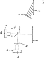
- Fig. 2 show a schematic representation of another image pickup device, in which the camera device 4 with a first and a second camera 4a, 4b is formed.
- the two cameras 4a, 4b are preceded by a respective optical filter 9a, 9b, the optical filters 9a, 9b each transmitting light of different wavelengths so that image recordings for illumination light of different wavelengths can be recorded with the two cameras 4a, 4b.
- the image recordings are made here by a partially transparent mirror 10, which transmits a respective part of the light beams to the first camera 4a and deflects it towards the second camera 4b.
Landscapes
- Physics & Mathematics (AREA)
- General Physics & Mathematics (AREA)
- Health & Medical Sciences (AREA)
- General Health & Medical Sciences (AREA)
- Toxicology (AREA)
- Image Input (AREA)
- Studio Devices (AREA)
- Facsimile Scanning Arrangements (AREA)
Abstract
Description
- Die Erfindung betrifft eine Bildaufnahmevorrichtung und ein Verfahren zum Aufnehmen einer Bildaufnahme eines Dokuments sowie die Verwendung.
- Derartige Bildaufnahmevorrichtungen und Verfahren werden genutzt, um Bildaufnahmen von Identitätsdokumenten zu machen. Die erfassten Bildaufnahmen können dann zu verschiedenen Zwecken genutzt werden, beispielsweise zum Bestimmen eines oder mehrerer Merkmale des Identitätsdokuments, um so zum Beispiel die Echtheit des Dokuments zu verifizieren oder eine Person zu identifizieren, der das Identitätsdokument zugeordnet ist. Hierbei kann vorgesehen sein, eine aktuelle Bildaufnahme mit einer oder mehrerer Referenzbildaufnahmen zu vergleichen, die zu einem früheren Zeitpunkt gemacht wurden, zum Beispiel referenzbildaufnahmen für ein oder mehrere Merkmale des Identitätsdokuments. Von besonderer Bedeutung ist es hierbei, dass die Bildaufnahmen unter reproduzierbaren Bildaufnahme-Bedingungen durchgeführt werden. Zu den Bildaufnahme-Bedingungen kann beispielsweise die relative Positionierung einer Beleuchtungseinrichtung, mit der das Identitätsdokument beleuchtet wird, und einer Kameraeinrichtung gehören, mit der die Bildaufnahme erfasst wird.
- Aus den Dokumenten
DE 10 2013 103 522 A1 sowieDE 10 2013 103 527 A1 sind Bildanalysesysteme zur Bildaufnahme eines Merkmals eines Identitätsdokuments bekannt. Es ist das Erfassen von Bildaufnahmen mit unterschiedlichen Beleuchtungswinkeln ermöglicht. - Aufgabe der Erfindung ist es, eine Bildaufnahmevorrichtung und ein Verfahren zum Aufnehmen einer Bildaufnahme eines Dokuments zu schaffen, bei denen reproduzierbare Bildaufnahme-Bedingungen auf effiziente Art und Weise bereitgestellt sind.
- Zur Lösung der Aufgabe sind eine Bildaufnahmevorrichtung sowie ein Verfahren zum Aufnehmen einer Bildaufnahme eines Dokuments nach den unabhängigen Ansprüchen 1 und 12 geschaffen. Ausgestaltungen sind Gegenstand von abhängigen Unteransprüchen.
- Nach einem Aspekt ist eine Bildaufnahmevorrichtung zum Aufnehmen einer Bildaufnahme eines Dokuments geschaffen. Die Bildaufnahmevorrichtung weist eine Auf- oder Ablageeinrichtung auf, die eingerichtet ist, ein Dokument für eine Bildaufnahme eines Merkmals des Identitätsdokuments ortsfest aufzunehmen. Eine Beleuchtungseinrichtung weist eine Lichtquelle zum Beleuchten des Dokuments für die Bildaufnahme auf, wenn dieses auf der Auflageeinrichtung abgelegt ist, und ist relativ zu dem Dokument in einer ersten Bewegungs-Sphäre verlagerbar, die sich zentriert zu einer Mitte des abgelegten Dokuments gegenüber dem Dokument im Wesentlichen halbkugelförmig aufspannt. Es ist eine Kameraeinrichtung vorgesehen, die eingerichtet ist, die Bildaufnahme des Dokuments zu erfassen, wenn dieses auf der Auflageeinrichtung abgelegt ist. Die Kameraeinrichtung ist relativ zu dem Dokument und der Beleuchtungseinrichtung in einer zweiten Bewegungs-Sphäre verlagerbar, die sich zentriert zur Mitte des abgelegten Dokuments gegenüber dem Dokument im Wesentlichen halbkugelförmig aufspannt. Die Bildaufnahmeeinrichtung weist eine Speichereinrichtung auf, die eingerichtet ist, der Bildaufnahme zugeordnete erste Positionsdaten, die eine Stellung der Beleuchtungseinrichtung in der ersten Bewegungs-Sphäre beim Aufnehmen oder Erfassen der Bildaufnahme anzeigen, und zweite Positionsdaten zu speichern, die eine Stellung der Kameraeinrichtung in der zweiten Bewegungs-Sphäre beim Erfassen der Bildaufnahme anzeigen.
- Nach einem weiteren Aspekt ist ein Verfahren zum Aufnehmen einer Bildaufnahme eines Dokuments geschaffen, wobei das Verfahren Folgendes aufweist: ortsfestes Ablegen eines Dokuments für eine Bildaufnahme eines Merkmals des Identitätsdokuments auf einer Auflageeinrichtung; Beleuchten des Dokuments mit einer Beleuchtungseinrichtung, die eine Lichtquelle zum Beleuchten des Dokuments für die wenigstens eine Bildaufnahme aufweist, wenn dieses auf der Auflageeinrichtung abgelegt ist, und die zum Einstellen relativ zu dem Dokument in einer ersten Bewegungs-Sphäre verlagert wird, die sich zentriert zu einer Mitte des abgelegten Dokuments gegenüber dem Dokument im Wesentlichen halbkugelförmig aufspannt; Erfassen der Bildaufnahme des Dokuments mit einer Kameraeinrichtung, die zum Einstellen vor der Bildaufnahme relativ zu dem Dokument und der Beleuchtungseinrichtung in einer zweiten Bewegungs-Sphäre verlagert wird, die sich zentriert zur Mitte des abgelegten Dokuments gegenüber dem Dokument im Wesentlichen halbkugel-förmig aufspannt; und Speichern von der Bildaufnahme zugeordneten ersten Positionsdaten, die eine Stellung der Beleuchtungseinrichtung in der ersten Bewegungs-Sphäre beim Erfassen der Bildaufnahme anzeigen, und zweiten Positionsdaten, die eine Stellung der Kameraeinrichtung in der zweiten Bewegungsebene beim Erfassen der Bildaufnahme anzeigen, in einer Speichereinrichtung.
- Die Verlagerbarkeit der Beleuchtungseinrichtung und der Kameraeinrichtung relativ zueinander sowie relativ zu dem Dokument auf der Auflageeinrichtung ermöglicht einerseits das Einstellen unterschiedlicher Bildaufnahme-Bedingungen. Andererseits sind die hierbei von der Beleuchtungseinrichtung und der Kameraeinrichtung eingenommenen Stellungen reproduzierbar, indem die ersten und die zweiten Positionsdaten bei einer (späteren) Bildaufnahme herangezogen werden. Insgesamt sind effizient reproduzierbare Bildaufnahme-Bedingungen bereitgestellt.
- Mithilfe des vorgeschlagenen Verfahrens können ein oder mehrere Bildaufnahmen für gleiche oder unterschiedliche Stellungen oder Positionen der Beleuchtungseinrichtung und / oder der Kameraeinrichtung aufgenommen werden. Einer einzelnen Bildaufnahme oder einer Folge von Bildaufnahmen werden die ersten und die zweiten Positionsdaten zugeordnet und in dieser zugeordneten Art und Weise in der Speichereinrichtung abgelegt. Die Zuordnung zwischen der Bildaufnahme und den Positionsdaten kann beispielsweise mithilfe eines Index in der Speichereinrichtung erfolgen. Auf diese Weise sind die Positionsdaten für die Beleuchtungseinrichtung und die Kameraeinrichtung elektronisch hinterlegt und stehen für ein Einstellen der Bildaufnahmevorrichtung bei einer späteren Bildaufnahme zur Verfügung, sodass diese für gleiche Bildaufnahme-Bedingungen hergerichtet wird.
- Wird eine Folge von Bildaufnahmen aufgenommen, beispielsweise eine Folge von aufeinanderfolgenden Bilder-Frames, können für jede der Bildaufnahmen in der Folge zugeordnete erste und zweite Positionsdaten gespeichert werden, wobei die Positionsdaten sich für die Bildaufnahmen unterscheiden, wenn zwischen den Bildaufnahmen die Beleuchtungseinrichtung und / oder die Kameraeinrichtung verlagert werden.
- Die eine oder die mehreren Bildaufnahmen können einer Bildanalyse unterzogen werden, insbesondere einer digitalen Bildanalyse, um ein oder mehrere Bildmerkmale (Dokumentmerkmale) zu bestimmen, beispielsweise ein oder mehrere Merkmale des Dokuments, zum Beispiel eines Identitätsdokuments. Die Bildaufnahme insgesamt und / oder hieraus bestimmte Merkmale können mit Referenzdaten (Referenzbildaufnahme, Referenzmerkmale) verglichen werden, wozu eine Auswerteeinrichtung nutzbar ist, die beispielsweise ein oder mehrere Prozessoren für eine Datenverarbeitung sowie einen Speicher aufweist, in dem zum Beispiel die Referenzdaten abgelegt sein können.
- Das Dokument kann ein zweidimensionales Objekt sein, zum Beispiel ein Identitätsdokument. Das zweidimensionale Objekt kann im Wesentlichen zum Bestimmen der Identität einer Person dienen. Es kann hierbei zum Beispiel ein Reisedokument, beispielweise ein Reisepass, eine Identitätskarte, beispielsweise ein deutscher Personalausweis oder Führerschein, oder eine Personstandsurkunde sein, beispielweise Geburts-, Heirats- oder Sterbeurkunde. Darüber hinaus kann es auch eine Urkunde, zu Beispiel Kfz-Brief oder notarielle Beglaubigung, oder eine Banknote sein.
- Die Beleuchtungseinrichtung kann mehrere Lichtquellen aufweisen. Die Lichtquellen können zum Beleuchten Licht unterschiedlicher Spektralbereiche und / oder mit verschiedenen Polarisationsrichtungen bereitstellend ausgeführt sein.
- Die Formulierung Bewegungs-Sphäre in der hier verwendeten Bedeutung betrifft allgemein eine Verlagerung oder Positionierung in einem dreidimensionalen Bewegungsraum, die gewölbt oder gekrümmt sein kann. Die Bewegungs-Sphäre kann zum Beispiel im Wesentlichen einem Abschnitt einer Kugeloberfläche entsprechen, beispielweise einer Halbkugelfläche.
- Die erste und die zweite Bewegungs-Sphäre können zusammenfallen. Bei dieser Ausführungsform sind die Beleuchtungseinrichtung und die Kameraeinrichtung in einer gemeinsamen Bewegungsebene gegenüber dem Dokument verlagerbar. Kameraeinrichtung und Beleuchtungseinrichtung können an verschiedenen Orten getrennt voneinander angeordnet sein.
- Ein Abstand zwischen der Kameraeinrichtung und dem Dokument auf der Auflageeinrichtung kann bei der Bildaufnahme etwa 30cm bis etwa 60cm betragen, bevorzugt etwa 40cm bis etwa 50cm. Auf diese Weise wird bei der Bildaufnahme die Ausbildung einer verbesserten Schärfentiefe unterstützt. Der Abstand zwischen dem Dokument und der Kameraeinrichtung ist ausreichend groß. Andererseits ist der Anforderung genüge getan, die Bildaufnahmevorrichtung in ihren Gesamtmessungen nicht zu groß gestalten zu müssen. Alternativ oder ergänzend kann vorgesehen sein, den Strahlengang beim Erfassen der Bildaufnahme zu falten oder Bildaufnahmen mit verschiedenen Schärfetiefen aufzunehmen und anschließend zu verrechnen. Dies kann zum Beispiel mittels aufeinanderfolgender Fokussierung auf mehrere konzentrische Ringe in einer abbildenden Ebene und anschließender Überlagerung der jeweils scharfen Pixel erreicht werden.
- Die Beleuchtungseinrichtung kann eingerichtet sein, das Dokument für die Bildaufnahme mit im Wesentlichen parallelen Lichtstrahlen zu beleuchten. Die im Wesentlichen parallelen Lichtstrahlen können mithilfe der Beleuchtungseinrichtung bereitgestellt werden, indem beispielsweise eine Lichtformeinrichtung das Licht aus der Lichtquelle vor dem Abstrahlen auf das Dokument formt. Eine Lichtformeinrichtung ist beispielsweise aus dem Dokument
DE 10 2014 205 363 A1 bekannt. - Die Beleuchtungseinrichtung kann einen flächigen Lichtstrahler aufweisen. Dieser kann eingerichtet sein, auf dem Dokument eine im Wesentlichen homogene Lichtverteilung zu erzeugen. Die Beleuchtungseinrichtung kann beispielsweise mit einer Beleuchtungsplatte gebildet sein, wie sie zum Beispiel im Dokument
DE 10 2014 205 363 A1 als solche beschrieben ist. - Die Beleuchtungseinrichtung kann eingerichtet sein, das Dokument mit Licht unterschiedlicher Wellenlängen zu beleuchten. Beispielsweise kann Licht im sichtbaren Wellenlängenbereich, im nahen Infrarot-Bereich und / oder im UV-Bereich verwendet werden. Bei dem Verfahren kann dann vorgesehen sein, Bildaufnahmen des Dokuments bei Beleuchtung mit Licht unterschiedlicher Wellenlängen aufzunehmen.
- Die Kameraeinrichtung kann mehrere Kameras aufweisen, und die Speichereinrichtung kann eingerichtet sein, der Bildaufnahme zugeordnete zweite Positionsdaten für die mehreren Kameras zu speichern, die eine jeweilige Stellung der mehreren Kameras in der zweiten Bewegungs-Sphäre beim Aufnehmen oder Erfassen der Bildaufnahme anzeigen. Bei dieser oder anderen Ausführungsformen kann die Nutzung ein oder mehrerer optischer Filter vorgesehen sein, die eingerichtet sind, nur Licht bestimmter Wellenlänge durchzulassen oder zu sperren, beispielsweise zum Blocken von Licht anderer Wellenlängen, derart, dass dieses nicht auf die Kamera einfällt. Wenn an verschiedenen Kameras unterschiedliche optische Filter verwendet werden, können mit den Kameras jeweils Bildaufnahmen für Beleuchtungslicht unterschiedlicher Wellenlängen aufgenommen werden.
- Die Beleuchtungseinrichtung und / oder die Kameraeinrichtung können zum Verlagern in der ersten oder der zweiten Bewegungsebene auf einem zugeordneten Tragarm mit einer Viertel- oder Halbkreisform angeordnet sein, wobei der zugeordnete Tragarm um eine Drehachse drehbar ist. Die Drehachse kann senkrecht auf der Oberfläche des abgelegten Dokuments stehen.
- Die Beleuchtungseinrichtung in der ersten Bewegungs-Sphäre und / oder die Kameraeinrichtung in der zweiten Bewegungs-Sphäre können mittels einer jeweiligen Stelleinrichtung verlagerbar sein. Die Stelleinrichtungen können mit einem jeweiligen Stellmotor gebildet sein, der ansteuerbar ist, um die Beleuchtungseinrichtung und / oder die Kameraeinrichtung in eine gewünschte Position oder Stellung für die Bildaufnahme zu verlagern. Hierbei können Benutzereingaben oder -einstellungen ausgewertet werden, um Steuersignale für das Verlagern der Beleuchtungseinrichtung und / oder der Kameraeinrichtung zu erzeugen. So kann der Benutzer über eine Benutzerschnittstelle eine Benutzereingabe machen, die eine gewünschte Stellung oder Position anzeigt, worauf ausgehend von der Benutzereingabe Steuersignale für die oder den Stellmotor erzeugt werden. Es kann alternativ oder ergänzend vorgesehen sein, dass die Stellmotoren mit Positionsgebern versehen sind, die Positionssignale für die jeweilige Stellung oder Position der Beleuchtungseinrichtung und / oder der Kameraeinrichtung ausgeben, die dann zum Bestimmen der ersten und / oder der zweiten Positionsdaten herangezogen werden können.
- Es kann vorgesehen sein, dass in Ergänzung zu den der Bildaufnahme zugeordneten ersten Positionsdaten erste Einstellungsdaten in der Speichereinrichtung gespeichert werden, die Meta-Daten bilden können. Weiterhin kann vorgesehen sein, dass in Ergänzung zu den der Bildaufnahme zugeordneten zweiten Positionsdaten zweite Einstellungsdaten in der Speichereinrichtung gespeichert werden. Die Einstellungsdaten, deren Zuordnung zu den Bildaufnahmen vergleichbar den Positionsdaten ausgeführt werden kann, geben in Ergänzung zu den Positionsdaten für die Beleuchtungseinrichtung und / oder die Kameraeinrichtung Parameter betreffend die jeweilige Einstellung bei den Bildaufnahmen an und können zum Beispiel einen oder mehrere Einstellparameter aus der folgenden Gruppe anzeigen: ein verwendetes Lichtspektrum, eine für die Bildaufnahmen eingestellte Lichtintensität, eine Polarisationsebene, einen oder mehrere verwendete Filter, einen oder mehrere Kameraparameter wie zum Beispiel Blende, Brennweite und / oder Belichtungszeit.
- In Verbindung mit dem Verfahren zum Aufnehmen der Bildaufnahme eines Identitätsdokuments können die vorangehend im Zusammenhang mit der Bildaufnahmevorrichtung beschriebenen Ausgestaltungen entsprechend vorgesehen sein.
- Bei der Verwendung des Verfahrens zum Bestimmen eines oder mehrerer Merkmale des Identitätsdokuments können das oder die im Rahmen der digitalen Bildanalyse bestimmten Merkmale des Identitätsdokuments mithilfe einer Auswerteeinrichtung weiter ausgewertet werden. Beispielsweise kann das Merkmal mit einem Referenzmerkmal verglichen werden, um die Echtheit des Identitätsdokuments zu verifizieren und / oder eine Person zu identifizieren, der das Identitätsdokument zugeordnet ist.
- Im Folgenden werden weitere Ausführungsbeispiele unter Bezugnahme auf Figuren einer Zeichnung näher erläutert. Hierbei zeigen:
- Fig. 1
- eine schematische perspektivische Darstellung einer Bildaufnahmevorrichtung und
- Fig. 2
- eine schematische Darstellung einer weiteren Bildaufnahmevorrichtung.
-
Fig. 1 zeigt eine schematische perspektivische Darstellung einer Bildaufnahmevorrichtung mit einer Auflageeinrichtung 1, auf der ein als Identitätsdokument ausgeführtes Dokument 2 abgelegt ist, derart, dass eine mithilfe einer Bildaufnahme zu erfassende Oberfläche des Dokuments 2 nach unten zeigt. Unterhalb des Dokuments 2 ist eine Trageinrichtung 3 mit einem ersten und einem zweiten Tragarm 3a, 3b angeordnet, die jeweils mithilfe eines Drehgelenks 4 um eine Drehachse 5 drehbar sind, die aufrecht auf einer Mitte 6 des Dokuments 2 steht. - An dem ersten Tragarm 3a, der mit einer Viertelkreisform gebildet ist, ist eine Kameraeinrichtung 7 aufgenommen, die entlang des ersten Tragarms 3a verlagerbar ist. Mittels des Verlagerns in unterschiedliche Stellungen oder Positionen entlang des ersten Tragarms 3 kann die optische Achse der Kameraeinrichtung 7 verschiedene Winkel zur Oberfläche des Dokuments 2 einnehmen.
- Vergleichbar ist eine Beleuchtungseinrichtung 8, die bei der gezeigten Ausführungsform mit einer Beleuchtungsplatte 9 gebildet ist, an dem zweiten Tragarm 3b aufgenommen. Die Beleuchtungseinrichtung 8 ist an dem eine Viertelkreisform aufweisenden zweiten Tragarm 3b entlang des Tragarms verlagerbar, sodass für die von der Beleuchtungseinrichtung 8 abgegebenen Lichtstrahlen unterschiedliche Einfallswinkel auf die Oberfläche des Dokuments 2 eingestellt werden können. Die Beleuchtungseinrichtung 8 ist eingerichtet, im Wesentlichen parallele Lichtstrahlen abzugeben. Hierzu kann die Beleuchtungsplatte 9 beispielsweise ausgeführt sein, wie dies beispielhaft in dem Dokument
DE 10 2014 205 363 A1 beschrieben ist. Schematisch dargestellt ist ein solcher Lichteinfall auf der rechten Seite inFig. 2 . - Mittels der Verlagerung entlang des jeweils zugeordneten Tragarms 3a, 3b sowie des Drehens um die Drehachse 5 können die Kameraeinrichtung 4 und die Beleuchtungseinrichtung 8 jeweils auf einer halbkugelförmig gebildeten Bewegungsebene in Bezug auf die erfassende Oberfläche des Dokuments 2 verlagert werden. Für die jeweilige Verlagerungsposition werden erste und zweite Positionsdaten bereitgestellt, die die Position der Kameraeinrichtung 4 sowie der Beleuchtungseinrichtung 8 in Bezug auf das Dokument 2, insbesondere die Mitte 6 des Dokuments 2, angeben. Hierzu kann vorgesehen sein, dass zur Verlagerung der Kameraeinrichtung 4 und der Beleuchtungseinrichtung 8 entlang des Tragarms 3a, 3b jeweils ein Stellmotor (nicht dargestellt) vorgesehen ist.
- Die angewendeten Steuersignale für die Stellmotoren geben dann einen Hinweis auf die jeweils als Folge der Steuersignale eingenommene Position an. Informationen hierüber können in einer Speichereinrichtung (nicht dargestellt) zusammen mit einer oder mehreren Bildaufnahmen abgelegt werden, die aufgenommen wurden, wenn die Kameraeinrichtung 4 und die Beleuchtungseinrichtung 8 in der Position angeordnet sind, die mit den Positionsdaten angezeigt wird. Auf diese Weise besteht eine direkte Zuordnung zwischen Bildaufnahme einerseits und Positionsdaten für die Kameraeinrichtung 4 und die Beleuchtungseinrichtung 8 andererseits. Die Speichereinrichtung kann als Teil der Bildaufnahmevorrichtung ausgebildet sein. Alternativ kann eine Schnittstelle vorgesehen sein, über welche die Positionsdaten und die Bilddaten zur Bildaufnahme an eine externe Speichereinrichtung übertragen werden, die beispielsweise Bestandteil einer Auswerteeinrichtung sein kann, die ihrerseits eingerichtet ist, eine Bildanalyse durchzuführen.
-
Fig. 2 zeig eine schematische Darstellung einer weiteren Bildaufnahmevorrichtung, bei der die Kameraeinrichtung 4 mit einer ersten und einer zweiten Kamera 4a, 4b gebildet ist. Den beiden Kameras 4a, 4b ist ein jeweilige optischer Filter 9a, 9b vorgelagert, wobei die optischen Filter 9a, 9b jeweils Licht unterschiedlicher Wellenlängen hindurchlassen, sodass mit den beiden Kameras 4a, 4b Bildaufnahmen für Beleuchtungslicht unterschiedlicher Wellenlänge aufgenommen werden können. Die Bildaufnahmen erfolgen hierbei durch einen teildurchlässigen Spiegel 10, welcher einen jeweiligen Teil der Lichtstrahlen zur ersten Kamera 4a durchlässt und zur zweiten Kamera 4b hin ablenkt. - Die in der vorstehenden Beschreibung, den Ansprüchen sowie der Zeichnung offenbarten Merkmale können sowohl einzeln als auch in beliebiger Kombination für die Verwirklichung der verschiedenen Ausführungen von Bedeutung sein.
Claims (13)
- Bildaufnahmevorrichtung zum Aufnehmen einer Bildaufnahme eines Dokuments, mit:- einer Auflageeinrichtung (1), die eingerichtet ist, ein Dokument (2) für eine Bildaufnahme eines Merkmals des Identitätsdokuments ortsfest aufzunehmen;- einer Beleuchtungseinrichtung (8), die eine Lichtquelle zum Beleuchten des Dokuments (2) für die Bildaufnahme aufweist, wenn dieses auf der Auflageeinrichtung (1) abgelegt ist, und die relativ zu dem Dokument (2) in einer ersten Bewegungs-Sphäre verlagerbar ist, die sich zentriert zu einer Mitte (6) des abgelegten Dokuments (2) gegenüber dem Dokument (2) im Wesentlichen halbkugelförmig aufspannt;- einer Kameraeinrichtung (4), die eingerichtet ist, die Bildaufnahme des Dokuments (2) zu erfassen, wenn dieses auf der Auflageeinrichtung (1) abgelegt ist, und die relativ zu dem Dokument (2) und der Beleuchtungseinrichtung (8) in einer zweiten Bewegungssphäre verlagerbar ist, die sich zentriert zur Mitte (6) des abgelegten Dokuments (2) gegenüber dem Dokument (2) im Wesentlichen halbkugelförmig aufspannt; und- einer Speichereinrichtung, die eingerichtet ist, der Bildaufnahme zugeordnete erste Positionsdaten, die eine Stellung der Beleuchtungseinrichtung (8) in der ersten Bewegungs-Sphäre beim Erfassen der Bildaufnahme anzeigen, und zweite Positionsdaten zu speichern, die eine Stellung der Kameraeinrichtung (4) in der zweiten Bewegungs-Sphäre beim Erfassen der Bildaufnahme anzeigen.
- Bildaufnahmevorrichtung nach Anspruch 1, dadurch gekennzeichnet, dass die erste und die zweite Bewegungs-Sphäre zusammenfallen.
- Bildaufnahmevorrichtung nach Anspruch 1 oder 2, dadurch gekennzeichnet, dass ein Abstand zwischen der Kameraeinrichtung (4) und dem Dokument (2) auf der Auflageeinrichtung (1) bei der Bildaufnahme etwa 30cm bis etwa 60cm beträgt, bevorzugt etwa 40cm bis etwa 50cm.
- Bildaufnahmevorrichtung nach mindestens einem der vorangehenden Ansprüche, dadurch gekennzeichnet, dass die Beleuchtungseinrichtung (8) eingerichtet ist, das Dokument (2) für die Bildaufnahme mit im Wesentlichen parallelen Lichtstrahlen zu beleuchten.
- Bildaufnahmevorrichtung nach mindestens einem der vorangehenden Ansprüche, dadurch gekennzeichnet, dass die Beleuchtungseinrichtung (8) einen flächigen Lichtstrahler (9) aufweist.
- Bildaufnahmevorrichtung nach mindestens einem der vorangehenden Ansprüche, dadurch gekennzeichnet, dass die Beleuchtungseinrichtung (8) eingerichtet ist, das Dokument (2) mit Licht unterschiedlicher Wellenlängen zu beleuchten.
- Bildaufnahmevorrichtung nach mindestens einem der vorangehenden Ansprüche, dadurch gekennzeichnet, dass die Kameraeinrichtung (4) mehrere Kameras (4a, 4b) aufweist und die Speichereinrichtung eingerichtet ist, der Bildaufnahme zugeordnete zweite Positionsdaten für die mehreren Kameras (4a, 4b) zu speichern, die eine jeweilige Stellung der mehreren Kameras (4a, 4b) in der zweiten Bewegungs-Sphäre beim Aufnehmen der Bildaufnahme anzeigen.
- Bildaufnahmevorrichtung nach mindestens einem der vorangehenden Ansprüche, dadurch gekennzeichnet, dass die Beleuchtungseinrichtung (8) und / oder die Kameraeinrichtung (4) zum Verlagern in der ersten oder der zweiten Bewegungs-Sphäre auf einem zugeordneten Tragarm (3a, 3b) mit einer Viertel- oder Halbkreisform angeordnet sind, wobei der zugeordnete Tragarm (3a, 3b) um eine Drehachse (5) drehbar ist.
- Bildaufnahmevorrichtung nach mindestens einem der vorangehenden Ansprüche, dadurch gekennzeichnet, dass die Beleuchtungseinrichtung (8) in der ersten Bewegungs-Sphäre und / oder die Kameraeinrichtung in der zweiten Bewegungs-Sphäre mittels einer jeweiligen Stelleinrichtung verlagerbar ist.
- Bildaufnahmevorrichtung nach mindestens einem der vorangehenden Ansprüche, dadurch gekennzeichnet, dass die Speichereinrichtung eingerichtet ist, der Bildaufnahme zugeordnete erste Einstellungsdaten zu speichern, die eine Einstellung der Beleuchtungseinrichtung (8) beim Erfassen der Bildaufnahme anzeigen.
- Bildaufnahmevorrichtung nach mindestens einem der vorangehenden Ansprüche, dadurch gekennzeichnet, dass die Speichereinrichtung eingerichtet ist, der Bildaufnahme zugeordnete zweite Einstellungsdaten zu speichern, die eine Einstellung der Kameraeinrichtung (4) beim Aufnehmen der Bildaufnahme anzeigen.
- Verfahren zum Aufnehmen einer Bildaufnahme eines Dokuments, mit:- ortsfestes Ablegen eines Dokuments (2) für eine Biidaufnahme eines Merkmals des Dokuments auf einer Auflageeinrichtung (1);- Beleuchten des Dokuments (2) mit einer Beleuchtungseinrichtung (8), die eine Lichtquelle zum Beleuchten des Dokuments (2) für die wenigstens eine Bildaufnahme aufweist, wenn dieses auf der Auflageeinrichtung (1) abgelegt ist, und die zum Einstellen relativ zu dem Dokument (2) in einer ersten Bewegungs-Sphäre verlagert wird, die sich zentriert zu einer Mitte (6) des abgelegten Dokuments (2) gegenüber dem Dokument (2) im Wesentlichen halbkugelförmig aufspannt;- Erfassen der Bildaufnahme des Dokuments (2) mit einer Kameraeinrichtung, die zum Einstellen vor der Bildaufnahme relativ zu dem Dokument (2) und der Beleuchtungseinrichtung (8) in einer zweiten Bewegungs-Sphäre verlagert wird, die sich zentriert zur Mitte (6) des abgelegten Dokuments (2) gegenüber dem Dokument (2) im Wesentlichen halbkugelförmig aufspannt; und- Speichern von der Bildaufnahme zugeordneten ersten Positionsdaten, die eine Stellung der Beleuchtungseinrichtung (8) in der ersten Bewegungs-Sphäre beim Erfassen der Bildaufnahme anzeigen, und zweiten Positionsdaten, die eine Stellung der Kameraeinrichtung in der zweiten Bewegungs-Sphäre beim Erfassen der Bildaufnahme anzeigen, in einer Speichereinrichtung.
- Verwendung eines Verfahrens nach Anspruch 12 zum Bestimmen eines Merkmals eines Dokuments, wobei bei dem Verfahren mithilfe einer Auswerteinrichtung eine digitale Bildanalyse der Bildaufnahme ausgeführt wird und bei der digitalen Bildanalyse ein Merkmal des Dokuments bestimmt wird.
Applications Claiming Priority (1)
| Application Number | Priority Date | Filing Date | Title |
|---|---|---|---|
| DE102018106181.1A DE102018106181A1 (de) | 2018-03-16 | 2018-03-16 | Bildaufnahmevorrichtung und Verfahren zum Aufnehmen einer Bildaufnahme eines Dokuments und Verwendung |
Publications (2)
| Publication Number | Publication Date |
|---|---|
| EP3540507A1 true EP3540507A1 (de) | 2019-09-18 |
| EP3540507B1 EP3540507B1 (de) | 2023-12-06 |
Family
ID=65818213
Family Applications (1)
| Application Number | Title | Priority Date | Filing Date |
|---|---|---|---|
| EP19163226.4A Active EP3540507B1 (de) | 2018-03-16 | 2019-03-15 | Bildaufnahmevorrichtung und verfahren zum aufnehmen einer bildaufnahme eines dokuments und verwendung |
Country Status (2)
| Country | Link |
|---|---|
| EP (1) | EP3540507B1 (de) |
| DE (1) | DE102018106181A1 (de) |
Cited By (1)
| Publication number | Priority date | Publication date | Assignee | Title |
|---|---|---|---|---|
| CN113037943A (zh) * | 2021-03-02 | 2021-06-25 | 上海圈讯互联网科技有限公司 | 一种基于高拍仪的信贷管理用快速拍摄方法 |
Citations (6)
| Publication number | Priority date | Publication date | Assignee | Title |
|---|---|---|---|---|
| US20040036841A1 (en) * | 2000-09-13 | 2004-02-26 | Jean-Michel Dbjay | Photographing system for producing vr editing |
| US20080122936A1 (en) * | 2006-11-23 | 2008-05-29 | Stephen Johnson Lomnes | System and method for imaging |
| DE102013103522A1 (de) | 2013-04-09 | 2014-10-09 | Bundesdruckerei Gmbh | Bildaufnahmesystem zur Bildaufnahme eines Merkmals eines Identifikationsdokumentes |
| DE102013103527A1 (de) | 2013-04-09 | 2014-10-09 | Bundesdruckerei Gmbh | Bildaufnahmesystem zur Bildaufnahme von Merkmalen eines Identifikationsdokumentes |
| US20150142409A1 (en) * | 2013-11-21 | 2015-05-21 | International Business Machines Corporation | Photographic setup modeling |
| DE102014205363A1 (de) | 2014-03-21 | 2015-09-24 | Bundesdruckerei Gmbh | Vorrichtung und Verfahren zur optischen Erfassung eines Dokuments und Verfahren zurHerstellung einer solchen Vorrichtung |
Family Cites Families (2)
| Publication number | Priority date | Publication date | Assignee | Title |
|---|---|---|---|---|
| GB2359953B (en) * | 2000-03-03 | 2004-02-11 | Hewlett Packard Co | Improvements relating to image capture systems |
| DE102013101587A1 (de) * | 2013-02-18 | 2014-08-21 | Bundesdruckerei Gmbh | Verfahren zum überprüfen der echtheit eines identifikationsdokumentes |
-
2018
- 2018-03-16 DE DE102018106181.1A patent/DE102018106181A1/de not_active Withdrawn
-
2019
- 2019-03-15 EP EP19163226.4A patent/EP3540507B1/de active Active
Patent Citations (6)
| Publication number | Priority date | Publication date | Assignee | Title |
|---|---|---|---|---|
| US20040036841A1 (en) * | 2000-09-13 | 2004-02-26 | Jean-Michel Dbjay | Photographing system for producing vr editing |
| US20080122936A1 (en) * | 2006-11-23 | 2008-05-29 | Stephen Johnson Lomnes | System and method for imaging |
| DE102013103522A1 (de) | 2013-04-09 | 2014-10-09 | Bundesdruckerei Gmbh | Bildaufnahmesystem zur Bildaufnahme eines Merkmals eines Identifikationsdokumentes |
| DE102013103527A1 (de) | 2013-04-09 | 2014-10-09 | Bundesdruckerei Gmbh | Bildaufnahmesystem zur Bildaufnahme von Merkmalen eines Identifikationsdokumentes |
| US20150142409A1 (en) * | 2013-11-21 | 2015-05-21 | International Business Machines Corporation | Photographic setup modeling |
| DE102014205363A1 (de) | 2014-03-21 | 2015-09-24 | Bundesdruckerei Gmbh | Vorrichtung und Verfahren zur optischen Erfassung eines Dokuments und Verfahren zurHerstellung einer solchen Vorrichtung |
Cited By (1)
| Publication number | Priority date | Publication date | Assignee | Title |
|---|---|---|---|---|
| CN113037943A (zh) * | 2021-03-02 | 2021-06-25 | 上海圈讯互联网科技有限公司 | 一种基于高拍仪的信贷管理用快速拍摄方法 |
Also Published As
| Publication number | Publication date |
|---|---|
| EP3540507B1 (de) | 2023-12-06 |
| DE102018106181A1 (de) | 2019-09-19 |
Similar Documents
| Publication | Publication Date | Title |
|---|---|---|
| DE69428686T2 (de) | Bildaufnahmevorrichtung und verfahren zur bestimmung von fokusinformationen | |
| DE102017101188B4 (de) | Mikroskop und Verfahren zum Mikroskopieren einer Probe | |
| EP2730092B1 (de) | Anordnung und verfahren zum bestimmen einer abbildungsabweichung einer kamera | |
| EP3598195A1 (de) | Verfahren zur mikroskopischen auswertung | |
| EP3123228B1 (de) | Konfokales mikroskop mit aperturkorrelation | |
| DE102009030644B4 (de) | Berührungslose Erfassungseinrichtung | |
| EP3291172A1 (de) | Verfahren zur ermittlung von ergebnisbilddaten | |
| EP3857304A2 (de) | Verfahren zum fokussieren einer kamera | |
| DE102019208114B4 (de) | Vorrichtung und Verfahren zur 3D Vermessung von Objektkoordinaten | |
| DE4121145C2 (de) | Objektdetektionssystem für optisches Instrument | |
| EP1178344A1 (de) | Verfahren und Vorrichtung zur Bildentzerrung in der Scanmikroskopie und Scanmikroskop | |
| EP1543471B1 (de) | Erfassen und greifen von gegenst nden | |
| DE102007038785A1 (de) | Verfahren und Vorrichtung zum Bestimmen von Geometriedaten eines Messobjekts | |
| EP1807790A1 (de) | Verfahren und vorrichtung für das erfassen von biometrischen daten | |
| EP3540507B1 (de) | Bildaufnahmevorrichtung und verfahren zum aufnehmen einer bildaufnahme eines dokuments und verwendung | |
| EP3320681B1 (de) | Verfahren und vorrichtung zum abtasten von oberflächen mit einer stereokamera | |
| DE102013103527A1 (de) | Bildaufnahmesystem zur Bildaufnahme von Merkmalen eines Identifikationsdokumentes | |
| DE102015110926A1 (de) | System zur Bestimmung einer Objektivposition | |
| DE102015116708A1 (de) | Dokument und Verfahren zum Verifizieren eines Dokuments | |
| WO2024032971A1 (de) | Vorrichtung und verfahren zur vermessung dreidimensionaler virtueller bilder und objekte eines head-up-displays | |
| DE4128039C2 (de) | Anordnung zum Erfassen von Niederschlag | |
| DE102017009334B3 (de) | Verfahren zum Prüfen eines optischen Systems | |
| DE102013210736A1 (de) | Vorrichtung zum Ermitteln der Lage von mechanischen Elementen | |
| DE102024207234B3 (de) | Verfahren zum Betrieb wenigstens einer Kamera eines Fahrzeugs, Kamerasystem, Computerprogramm, Datenträger und Fahrzeug | |
| DE102009025324B4 (de) | Verfahren und Erfassungsvorrichtung mit einem Kontakt-Bildsensor zum Erfassen räumlicher Strukturen |
Legal Events
| Date | Code | Title | Description |
|---|---|---|---|
| PUAI | Public reference made under article 153(3) epc to a published international application that has entered the european phase |
Free format text: ORIGINAL CODE: 0009012 |
|
| STAA | Information on the status of an ep patent application or granted ep patent |
Free format text: STATUS: THE APPLICATION HAS BEEN PUBLISHED |
|
| AK | Designated contracting states |
Kind code of ref document: A1 Designated state(s): AL AT BE BG CH CY CZ DE DK EE ES FI FR GB GR HR HU IE IS IT LI LT LU LV MC MK MT NL NO PL PT RO RS SE SI SK SM TR |
|
| AX | Request for extension of the european patent |
Extension state: BA ME |
|
| STAA | Information on the status of an ep patent application or granted ep patent |
Free format text: STATUS: REQUEST FOR EXAMINATION WAS MADE |
|
| 17P | Request for examination filed |
Effective date: 20200317 |
|
| RBV | Designated contracting states (corrected) |
Designated state(s): AL AT BE BG CH CY CZ DE DK EE ES FI FR GB GR HR HU IE IS IT LI LT LU LV MC MK MT NL NO PL PT RO RS SE SI SK SM TR |
|
| STAA | Information on the status of an ep patent application or granted ep patent |
Free format text: STATUS: EXAMINATION IS IN PROGRESS |
|
| 17Q | First examination report despatched |
Effective date: 20210914 |
|
| P01 | Opt-out of the competence of the unified patent court (upc) registered |
Effective date: 20230526 |
|
| GRAP | Despatch of communication of intention to grant a patent |
Free format text: ORIGINAL CODE: EPIDOSNIGR1 |
|
| STAA | Information on the status of an ep patent application or granted ep patent |
Free format text: STATUS: GRANT OF PATENT IS INTENDED |
|
| INTG | Intention to grant announced |
Effective date: 20230707 |
|
| GRAS | Grant fee paid |
Free format text: ORIGINAL CODE: EPIDOSNIGR3 |
|
| GRAA | (expected) grant |
Free format text: ORIGINAL CODE: 0009210 |
|
| STAA | Information on the status of an ep patent application or granted ep patent |
Free format text: STATUS: THE PATENT HAS BEEN GRANTED |
|
| AK | Designated contracting states |
Kind code of ref document: B1 Designated state(s): AL AT BE BG CH CY CZ DE DK EE ES FI FR GB GR HR HU IE IS IT LI LT LU LV MC MK MT NL NO PL PT RO RS SE SI SK SM TR |
|
| REG | Reference to a national code |
Ref country code: GB Ref legal event code: FG4D Free format text: NOT ENGLISH |
|
| REG | Reference to a national code |
Ref country code: CH Ref legal event code: EP |
|
| REG | Reference to a national code |
Ref country code: DE Ref legal event code: R096 Ref document number: 502019010056 Country of ref document: DE |
|
| REG | Reference to a national code |
Ref country code: IE Ref legal event code: FG4D Free format text: LANGUAGE OF EP DOCUMENT: GERMAN |
|
| REG | Reference to a national code |
Ref country code: LT Ref legal event code: MG9D |
|
| PG25 | Lapsed in a contracting state [announced via postgrant information from national office to epo] |
Ref country code: GR Free format text: LAPSE BECAUSE OF FAILURE TO SUBMIT A TRANSLATION OF THE DESCRIPTION OR TO PAY THE FEE WITHIN THE PRESCRIBED TIME-LIMIT Effective date: 20240307 |
|
| REG | Reference to a national code |
Ref country code: NL Ref legal event code: MP Effective date: 20231206 |
|
| PG25 | Lapsed in a contracting state [announced via postgrant information from national office to epo] |
Ref country code: LT Free format text: LAPSE BECAUSE OF FAILURE TO SUBMIT A TRANSLATION OF THE DESCRIPTION OR TO PAY THE FEE WITHIN THE PRESCRIBED TIME-LIMIT Effective date: 20231206 |
|
| PG25 | Lapsed in a contracting state [announced via postgrant information from national office to epo] |
Ref country code: ES Free format text: LAPSE BECAUSE OF FAILURE TO SUBMIT A TRANSLATION OF THE DESCRIPTION OR TO PAY THE FEE WITHIN THE PRESCRIBED TIME-LIMIT Effective date: 20231206 |
|
| PG25 | Lapsed in a contracting state [announced via postgrant information from national office to epo] |
Ref country code: LT Free format text: LAPSE BECAUSE OF FAILURE TO SUBMIT A TRANSLATION OF THE DESCRIPTION OR TO PAY THE FEE WITHIN THE PRESCRIBED TIME-LIMIT Effective date: 20231206 Ref country code: GR Free format text: LAPSE BECAUSE OF FAILURE TO SUBMIT A TRANSLATION OF THE DESCRIPTION OR TO PAY THE FEE WITHIN THE PRESCRIBED TIME-LIMIT Effective date: 20240307 Ref country code: ES Free format text: LAPSE BECAUSE OF FAILURE TO SUBMIT A TRANSLATION OF THE DESCRIPTION OR TO PAY THE FEE WITHIN THE PRESCRIBED TIME-LIMIT Effective date: 20231206 Ref country code: BG Free format text: LAPSE BECAUSE OF FAILURE TO SUBMIT A TRANSLATION OF THE DESCRIPTION OR TO PAY THE FEE WITHIN THE PRESCRIBED TIME-LIMIT Effective date: 20240306 |
|
| PG25 | Lapsed in a contracting state [announced via postgrant information from national office to epo] |
Ref country code: NL Free format text: LAPSE BECAUSE OF FAILURE TO SUBMIT A TRANSLATION OF THE DESCRIPTION OR TO PAY THE FEE WITHIN THE PRESCRIBED TIME-LIMIT Effective date: 20231206 |
|
| PG25 | Lapsed in a contracting state [announced via postgrant information from national office to epo] |
Ref country code: SE Free format text: LAPSE BECAUSE OF FAILURE TO SUBMIT A TRANSLATION OF THE DESCRIPTION OR TO PAY THE FEE WITHIN THE PRESCRIBED TIME-LIMIT Effective date: 20231206 Ref country code: RS Free format text: LAPSE BECAUSE OF FAILURE TO SUBMIT A TRANSLATION OF THE DESCRIPTION OR TO PAY THE FEE WITHIN THE PRESCRIBED TIME-LIMIT Effective date: 20231206 Ref country code: NO Free format text: LAPSE BECAUSE OF FAILURE TO SUBMIT A TRANSLATION OF THE DESCRIPTION OR TO PAY THE FEE WITHIN THE PRESCRIBED TIME-LIMIT Effective date: 20240306 Ref country code: NL Free format text: LAPSE BECAUSE OF FAILURE TO SUBMIT A TRANSLATION OF THE DESCRIPTION OR TO PAY THE FEE WITHIN THE PRESCRIBED TIME-LIMIT Effective date: 20231206 Ref country code: LV Free format text: LAPSE BECAUSE OF FAILURE TO SUBMIT A TRANSLATION OF THE DESCRIPTION OR TO PAY THE FEE WITHIN THE PRESCRIBED TIME-LIMIT Effective date: 20231206 Ref country code: HR Free format text: LAPSE BECAUSE OF FAILURE TO SUBMIT A TRANSLATION OF THE DESCRIPTION OR TO PAY THE FEE WITHIN THE PRESCRIBED TIME-LIMIT Effective date: 20231206 |
|
| PG25 | Lapsed in a contracting state [announced via postgrant information from national office to epo] |
Ref country code: IS Free format text: LAPSE BECAUSE OF FAILURE TO SUBMIT A TRANSLATION OF THE DESCRIPTION OR TO PAY THE FEE WITHIN THE PRESCRIBED TIME-LIMIT Effective date: 20240406 |
|
| PG25 | Lapsed in a contracting state [announced via postgrant information from national office to epo] |
Ref country code: CZ Free format text: LAPSE BECAUSE OF FAILURE TO SUBMIT A TRANSLATION OF THE DESCRIPTION OR TO PAY THE FEE WITHIN THE PRESCRIBED TIME-LIMIT Effective date: 20231206 |
|
| PG25 | Lapsed in a contracting state [announced via postgrant information from national office to epo] |
Ref country code: SK Free format text: LAPSE BECAUSE OF FAILURE TO SUBMIT A TRANSLATION OF THE DESCRIPTION OR TO PAY THE FEE WITHIN THE PRESCRIBED TIME-LIMIT Effective date: 20231206 |
|
| PG25 | Lapsed in a contracting state [announced via postgrant information from national office to epo] |
Ref country code: SM Free format text: LAPSE BECAUSE OF FAILURE TO SUBMIT A TRANSLATION OF THE DESCRIPTION OR TO PAY THE FEE WITHIN THE PRESCRIBED TIME-LIMIT Effective date: 20231206 Ref country code: SK Free format text: LAPSE BECAUSE OF FAILURE TO SUBMIT A TRANSLATION OF THE DESCRIPTION OR TO PAY THE FEE WITHIN THE PRESCRIBED TIME-LIMIT Effective date: 20231206 Ref country code: RO Free format text: LAPSE BECAUSE OF FAILURE TO SUBMIT A TRANSLATION OF THE DESCRIPTION OR TO PAY THE FEE WITHIN THE PRESCRIBED TIME-LIMIT Effective date: 20231206 Ref country code: IT Free format text: LAPSE BECAUSE OF FAILURE TO SUBMIT A TRANSLATION OF THE DESCRIPTION OR TO PAY THE FEE WITHIN THE PRESCRIBED TIME-LIMIT Effective date: 20231206 Ref country code: IS Free format text: LAPSE BECAUSE OF FAILURE TO SUBMIT A TRANSLATION OF THE DESCRIPTION OR TO PAY THE FEE WITHIN THE PRESCRIBED TIME-LIMIT Effective date: 20240406 Ref country code: EE Free format text: LAPSE BECAUSE OF FAILURE TO SUBMIT A TRANSLATION OF THE DESCRIPTION OR TO PAY THE FEE WITHIN THE PRESCRIBED TIME-LIMIT Effective date: 20231206 Ref country code: CZ Free format text: LAPSE BECAUSE OF FAILURE TO SUBMIT A TRANSLATION OF THE DESCRIPTION OR TO PAY THE FEE WITHIN THE PRESCRIBED TIME-LIMIT Effective date: 20231206 |
|
| PG25 | Lapsed in a contracting state [announced via postgrant information from national office to epo] |
Ref country code: PL Free format text: LAPSE BECAUSE OF FAILURE TO SUBMIT A TRANSLATION OF THE DESCRIPTION OR TO PAY THE FEE WITHIN THE PRESCRIBED TIME-LIMIT Effective date: 20231206 Ref country code: PT Free format text: LAPSE BECAUSE OF FAILURE TO SUBMIT A TRANSLATION OF THE DESCRIPTION OR TO PAY THE FEE WITHIN THE PRESCRIBED TIME-LIMIT Effective date: 20240408 |
|
| PG25 | Lapsed in a contracting state [announced via postgrant information from national office to epo] |
Ref country code: PT Free format text: LAPSE BECAUSE OF FAILURE TO SUBMIT A TRANSLATION OF THE DESCRIPTION OR TO PAY THE FEE WITHIN THE PRESCRIBED TIME-LIMIT Effective date: 20240408 Ref country code: PL Free format text: LAPSE BECAUSE OF FAILURE TO SUBMIT A TRANSLATION OF THE DESCRIPTION OR TO PAY THE FEE WITHIN THE PRESCRIBED TIME-LIMIT Effective date: 20231206 |
|
| REG | Reference to a national code |
Ref country code: DE Ref legal event code: R097 Ref document number: 502019010056 Country of ref document: DE |
|
| PG25 | Lapsed in a contracting state [announced via postgrant information from national office to epo] |
Ref country code: DK Free format text: LAPSE BECAUSE OF FAILURE TO SUBMIT A TRANSLATION OF THE DESCRIPTION OR TO PAY THE FEE WITHIN THE PRESCRIBED TIME-LIMIT Effective date: 20231206 |
|
| PLBE | No opposition filed within time limit |
Free format text: ORIGINAL CODE: 0009261 |
|
| STAA | Information on the status of an ep patent application or granted ep patent |
Free format text: STATUS: NO OPPOSITION FILED WITHIN TIME LIMIT |
|
| PG25 | Lapsed in a contracting state [announced via postgrant information from national office to epo] |
Ref country code: SI Free format text: LAPSE BECAUSE OF FAILURE TO SUBMIT A TRANSLATION OF THE DESCRIPTION OR TO PAY THE FEE WITHIN THE PRESCRIBED TIME-LIMIT Effective date: 20231206 |
|
| PG25 | Lapsed in a contracting state [announced via postgrant information from national office to epo] |
Ref country code: SI Free format text: LAPSE BECAUSE OF FAILURE TO SUBMIT A TRANSLATION OF THE DESCRIPTION OR TO PAY THE FEE WITHIN THE PRESCRIBED TIME-LIMIT Effective date: 20231206 Ref country code: DK Free format text: LAPSE BECAUSE OF FAILURE TO SUBMIT A TRANSLATION OF THE DESCRIPTION OR TO PAY THE FEE WITHIN THE PRESCRIBED TIME-LIMIT Effective date: 20231206 |
|
| REG | Reference to a national code |
Ref country code: CH Ref legal event code: PL |
|
| 26N | No opposition filed |
Effective date: 20240909 |
|
| PG25 | Lapsed in a contracting state [announced via postgrant information from national office to epo] |
Ref country code: LU Free format text: LAPSE BECAUSE OF NON-PAYMENT OF DUE FEES Effective date: 20240315 |
|
| PG25 | Lapsed in a contracting state [announced via postgrant information from national office to epo] |
Ref country code: MC Free format text: LAPSE BECAUSE OF FAILURE TO SUBMIT A TRANSLATION OF THE DESCRIPTION OR TO PAY THE FEE WITHIN THE PRESCRIBED TIME-LIMIT Effective date: 20231206 |
|
| GBPC | Gb: european patent ceased through non-payment of renewal fee |
Effective date: 20240315 |
|
| PG25 | Lapsed in a contracting state [announced via postgrant information from national office to epo] |
Ref country code: MC Free format text: LAPSE BECAUSE OF FAILURE TO SUBMIT A TRANSLATION OF THE DESCRIPTION OR TO PAY THE FEE WITHIN THE PRESCRIBED TIME-LIMIT Effective date: 20231206 Ref country code: LU Free format text: LAPSE BECAUSE OF NON-PAYMENT OF DUE FEES Effective date: 20240315 |
|
| REG | Reference to a national code |
Ref country code: BE Ref legal event code: MM Effective date: 20240331 |
|
| PG25 | Lapsed in a contracting state [announced via postgrant information from national office to epo] |
Ref country code: BE Free format text: LAPSE BECAUSE OF NON-PAYMENT OF DUE FEES Effective date: 20240331 |
|
| PG25 | Lapsed in a contracting state [announced via postgrant information from national office to epo] |
Ref country code: GB Free format text: LAPSE BECAUSE OF NON-PAYMENT OF DUE FEES Effective date: 20240315 |
|
| PG25 | Lapsed in a contracting state [announced via postgrant information from national office to epo] |
Ref country code: FR Free format text: LAPSE BECAUSE OF NON-PAYMENT OF DUE FEES Effective date: 20240331 |
|
| PG25 | Lapsed in a contracting state [announced via postgrant information from national office to epo] |
Ref country code: IE Free format text: LAPSE BECAUSE OF NON-PAYMENT OF DUE FEES Effective date: 20240315 |
|
| PG25 | Lapsed in a contracting state [announced via postgrant information from national office to epo] |
Ref country code: IE Free format text: LAPSE BECAUSE OF NON-PAYMENT OF DUE FEES Effective date: 20240315 Ref country code: GB Free format text: LAPSE BECAUSE OF NON-PAYMENT OF DUE FEES Effective date: 20240315 Ref country code: FR Free format text: LAPSE BECAUSE OF NON-PAYMENT OF DUE FEES Effective date: 20240331 Ref country code: BE Free format text: LAPSE BECAUSE OF NON-PAYMENT OF DUE FEES Effective date: 20240331 Ref country code: CH Free format text: LAPSE BECAUSE OF NON-PAYMENT OF DUE FEES Effective date: 20240331 |
|
| REG | Reference to a national code |
Ref country code: AT Ref legal event code: MM01 Ref document number: 1638966 Country of ref document: AT Kind code of ref document: T Effective date: 20240315 |
|
| PG25 | Lapsed in a contracting state [announced via postgrant information from national office to epo] |
Ref country code: AT Free format text: LAPSE BECAUSE OF NON-PAYMENT OF DUE FEES Effective date: 20240315 |
|
| PG25 | Lapsed in a contracting state [announced via postgrant information from national office to epo] |
Ref country code: CY Free format text: LAPSE BECAUSE OF FAILURE TO SUBMIT A TRANSLATION OF THE DESCRIPTION OR TO PAY THE FEE WITHIN THE PRESCRIBED TIME-LIMIT; INVALID AB INITIO Effective date: 20190315 |
|
| PG25 | Lapsed in a contracting state [announced via postgrant information from national office to epo] |
Ref country code: HU Free format text: LAPSE BECAUSE OF FAILURE TO SUBMIT A TRANSLATION OF THE DESCRIPTION OR TO PAY THE FEE WITHIN THE PRESCRIBED TIME-LIMIT; INVALID AB INITIO Effective date: 20190315 |
|
| PG25 | Lapsed in a contracting state [announced via postgrant information from national office to epo] |
Ref country code: FI Free format text: LAPSE BECAUSE OF FAILURE TO SUBMIT A TRANSLATION OF THE DESCRIPTION OR TO PAY THE FEE WITHIN THE PRESCRIBED TIME-LIMIT Effective date: 20231207 |
|
| PG25 | Lapsed in a contracting state [announced via postgrant information from national office to epo] |
Ref country code: TR Free format text: LAPSE BECAUSE OF FAILURE TO SUBMIT A TRANSLATION OF THE DESCRIPTION OR TO PAY THE FEE WITHIN THE PRESCRIBED TIME-LIMIT Effective date: 20231206 |
|
| PGFP | Annual fee paid to national office [announced via postgrant information from national office to epo] |
Ref country code: DE Payment date: 20260320 Year of fee payment: 8 |