EP3540500B1 - Multi-channel phase-capable acousto-optic modulator (aom) including beam stabilizer and related methods - Google Patents
Multi-channel phase-capable acousto-optic modulator (aom) including beam stabilizer and related methods Download PDFInfo
- Publication number
- EP3540500B1 EP3540500B1 EP19159311.0A EP19159311A EP3540500B1 EP 3540500 B1 EP3540500 B1 EP 3540500B1 EP 19159311 A EP19159311 A EP 19159311A EP 3540500 B1 EP3540500 B1 EP 3540500B1
- Authority
- EP
- European Patent Office
- Prior art keywords
- laser light
- light beam
- laser
- stabilizer
- acousto
- Prior art date
- Legal status (The legal status is an assumption and is not a legal conclusion. Google has not performed a legal analysis and makes no representation as to the accuracy of the status listed.)
- Active
Links
Images


Classifications
-
- G—PHYSICS
- G02—OPTICS
- G02F—OPTICAL DEVICES OR ARRANGEMENTS FOR THE CONTROL OF LIGHT BY MODIFICATION OF THE OPTICAL PROPERTIES OF THE MEDIA OF THE ELEMENTS INVOLVED THEREIN; NON-LINEAR OPTICS; FREQUENCY-CHANGING OF LIGHT; OPTICAL LOGIC ELEMENTS; OPTICAL ANALOGUE/DIGITAL CONVERTERS
- G02F1/00—Devices or arrangements for the control of the intensity, colour, phase, polarisation or direction of light arriving from an independent light source, e.g. switching, gating or modulating; Non-linear optics
- G02F1/01—Devices or arrangements for the control of the intensity, colour, phase, polarisation or direction of light arriving from an independent light source, e.g. switching, gating or modulating; Non-linear optics for the control of the intensity, phase, polarisation or colour
- G02F1/11—Devices or arrangements for the control of the intensity, colour, phase, polarisation or direction of light arriving from an independent light source, e.g. switching, gating or modulating; Non-linear optics for the control of the intensity, phase, polarisation or colour based on acousto-optical elements, e.g. using variable diffraction by sound or like mechanical waves
- G02F1/113—Circuit or control arrangements
-
- G—PHYSICS
- G02—OPTICS
- G02F—OPTICAL DEVICES OR ARRANGEMENTS FOR THE CONTROL OF LIGHT BY MODIFICATION OF THE OPTICAL PROPERTIES OF THE MEDIA OF THE ELEMENTS INVOLVED THEREIN; NON-LINEAR OPTICS; FREQUENCY-CHANGING OF LIGHT; OPTICAL LOGIC ELEMENTS; OPTICAL ANALOGUE/DIGITAL CONVERTERS
- G02F1/00—Devices or arrangements for the control of the intensity, colour, phase, polarisation or direction of light arriving from an independent light source, e.g. switching, gating or modulating; Non-linear optics
- G02F1/29—Devices or arrangements for the control of the intensity, colour, phase, polarisation or direction of light arriving from an independent light source, e.g. switching, gating or modulating; Non-linear optics for the control of the position or the direction of light beams, i.e. deflection
- G02F1/33—Acousto-optical deflection devices
Definitions
- the present invention relates to the field of optical devices, and, more particularly, to acousto-optic modulators for lasers and related methods.
- Acousto-optic modulators sometimes referred to as Bragg cells, diffract and shift light using sound waves at radio frequency. These devices are often used for Q-switching, signal modulation in telecommunications systems, laser scanning and beam intensity control, frequency shifting, and wavelength filtering in spectroscopy systems. Many other applications lend themselves to using acousto-optic devices.
- a piezoelectric transducer In such acousto-optic devices, a piezoelectric transducer, sometimes also referred to as an RF transducer, is secured to an acousto-optic bulk medium as a transparent optical material, for example, fused silica, quartz or similar glass material.
- An electric RF signal oscillates and drives the transducer to vibrate and create sound waves within the transparent medium which effect the properties of an optical field in the medium via the photo elastic effect, in which a modulating strain field of an ultrasonic wave is coupled to an index of refraction for the acousto-optic bulk medium.
- the refractive index change in amplitude is proportional to that of sound.
- the index of refraction is changed by moving periodic planes of expansion and compression in the acousto-optic bulk material. Incoming light scatters because of the resulting periodic index modulation and interference, similar to Bragg diffraction.
- Acousto-optic modulators are preferred in many applications because they are faster than tiltable mirrors and other mechanical devices.
- the time it takes for the acousto-optic modulator to shift an exiting optical beam is limited to the transit time of the sound wave.
- the acousto-optic modulators are often used in Q-switches where a laser produces a pulsed output beam at high peak power, typically in the Kilowatt range. This output could be higher than lasers operating a continuous wave (CW) or constant output mode.
- US 7,538,929 B2 discloses an acousto-optic modulator including an acousto-optic bulk medium and transducer attached to the acousto-optic bulk medium and formed as a linear array of electrodes.
- a transducer driver is connected to each electrode and is coherently phase driven to alter the angular momentum distribution of an acoustic field and alternately allow and inhibit phase matching between the optical and acoustic field and produce a desired intensity modulation of an optical wavefront.
- Some applications using acousto-optic devices modulate the intensity of an optical beam. This modulation may create small deviations in the output angle of the diffracted beam because of the local thermal transients introduced when the RF modulation waveform to the device is turned ON and OFF. These thermal transients may negatively impact the resolution and location of the focused spot, which may be produced.
- One advantageous approach which may be used to help enhance the resolution of acousto-optic devices is set forth in U.S. Pat. No.
- Wasilousky discloses an acousto-optic modulator which includes an acousto-optic bulk medium and transducer attached to the acousto-optic bulk medium and formed as a linear array of electrodes.
- a transducer driver is connected to each electrode and is coherently phase driven to alter the angular momentum distribution of an acoustic field and alternately allow and inhibit phase matching between the optical and acoustic field and produce a desired intensity modulation of an optical wavefront.
- a laser system may include a laser source configured to generate a first laser light beam, a beam stabilizer downstream from the laser source and configured to stabilize the first laser light beam, and a beamsplitter downstream from the beam stabilizer and configured to split the stabilized first laser light beam into a plurality of second laser light beams.
- the system may further include a multi-channel acousto-optic modulator (AOM) including a common acousto-optic medium configured to receive the plurality of second laser light beams, and a respective phase array transducer comprising a plurality of electrodes coupled to the common acousto-optic medium for each of the second laser light beams.
- AOM a multi-channel acousto-optic modulator
- the system may further include a plurality of radio frequency (RF) drivers each configured to generate respective RF drive signals for the phased array transducer electrodes.
- RF radio frequency
- the beam stabilizer may be configured to correct a positional displacement of the laser light beam.
- the beam stabilizer may include a position mirror optically aligned with the first laser light beam from the laser source, a servo motor configured to move the position mirror, a position sensor configured to measure a positional displacement of the laser light beam, and a servo controller coupled to the servo motor and configured to actuate the servo motor to stabilize the first laser light beam based upon the position sensor.
- the beam stabilizer may be configured to correct an angular displacement of the laser light beam. More particularly, the beam stabilizer may include an angle mirror optically aligned with the first laser light beam from the laser source, a servo motor configured to move the angle mirror, an angle sensor configured to measure an angular displacement of the laser light beam, and a servo controller coupled to the servo motor and configured to actuate the servo motor to stabilize the first laser light beam based upon the angle sensor.
- Each RF driver may be configured to drive alternating electrodes of the respective phased array transducer electrodes with different phases.
- each RF driver may be configured to drive the alternating electrodes of the respective phased array transducer electrodes with different phases within a range of 0° to 180°.
- an RF power level associated with each RF drive signal may have a constant power.
- the electrodes of each phased array transducer may be less than 500 ⁇ m apart from one another at centers thereof.
- a related method may include generating a first laser light beam using a laser source, stabilizing the first laser light beam using a beam stabilizer downstream from the laser source, and splitting the stabilized first laser light beam into a plurality of second laser light beams using a beamsplitter downstream from the beam stabilizer.
- the method may further include receiving the plurality of second laser light beams at a common acousto-optic medium, and generating respective RF drive signals for a plurality of phased array transducer electrodes coupled to the common acousto-optic medium for each of the second laser light beams using a plurality of RF drivers.
- a laser system 130 which provides multi-channel operation and associated method aspects are now described.
- typical multi-channel acousto-optic (AO) devices suffer from excessive beam pointing errors due to data dependent thermal transients generated in the ultrasonic transducer and bulk optical substrate material.
- beam pointing errors correlate to noise in quantum state manipulation systems.
- inter-channel acoustic crosstalk is a major source of data dependent variation in the modulated optical beam intensity.
- the multi-channel system 130 illustratively includes a laser source 131 which generates a first laser light beam 141, at Block 72.
- the laser source 131 may be similar to the laser source 31 described above.
- a diffractive/refractive beam splitter 142 divides the first laser light beam 141 into a plurality of second laser light beams 143, at Block 73, which in the illustrated example is four, although other numbers of beams (e.g., 8, 32, etc.) may be used depending upon the given application.
- the second laser light beams 143 are received by a common phase modulation acousto-optic medium 133 of a multi-channel AOM 132.
- the acousto-optic medium 133 is common to all of the second laser light beams, i.e., the same acousto-optic medium is used to modulate each of the second laser light beams.
- the acousto-optic medium 133 may be similar to those described above. However, it should be noted that the phase-capable multi-channel AOM 132 need not be used, and that an amplitude modulation AOM may instead by used, for example.
- the AOM 132 further includes multiple transducers, each comprising respective electrodes 134, for each of the second laser light beams 143 coupled to the common acousto-optic medium 133.
- the laser system 130 further illustratively includes a plurality of RF drivers 136 each configured to generate the requisite RF drive signals for their respective phased array transducer electrodes 134, at Block 74, which illustratively concludes the method of FIG. 7 (Block 75 ).
- each RF driver 136 may be configured to drive alternating electrodes of the respective array of transducer electrodes 134 with different phases. More particularly, two example configurations for driving alternating electrodes 40 of the array of transducer electrodes 34 with different phases are now described.
- first and third driving signals shown on the right hand side of FIG. 3
- second and fourth driving signals provided to corresponding even numbered electrodes.
- first and second drive signals are respectively connected to odd and even electrodes in an interdigitated fashion as shown, and as before these drive signals are 180o out of phase to one another.
- the RF drive signals need not always be 180° out of phase, i.e., they may be somewhere between 0o and 180o to vary the level of phase matching occurring in the AO diffraction process.
- Such a bi-phase configuration helps to eliminate beam deflection due to thermal transients generated when channel data is switched on and off, i.e., by using phase modulation only. More particularly, a bi-phase approach maintains the RF Signal "ON” and only flips the phase of the drive signal to alternating elements, as opposed to a conventional amplitude modulation approach in which optical modulation is achieved by turning the RF signal "ON” and "OFF".
- the present approach may accordingly reduce time average thermal gradients produced by the aggregate array during normal operation since the RF power level is essentially constant or stationary, which helps to minimize polarization corruption and gross beam offset. This further helps to reduce beam intensity fluctuations produced by inter-channel acoustic crosstalk by minimizing changes in the adjacent channel strain field due to changes in local channel data.
- the transducer electrodes 134 may be implemented as metalizations on the piezoelectric AO medium 133, which are spaced apart 500 ⁇ m or less at their centers, and more particularly 450 ⁇ m or less. However, other dimensions may be used in different embodiments.
- phase modulation capable acousto-optic modulator or transducer structure in a multi-channel device configuration provides significant advantages. More particularly, phase modulation used with pulse code (ON/OFF) modulation provides inherently better pointing stability, since the RF power applied to the device remains substantially constant at all times, even during data input bit transitions. Moreover, the effects of inter-channel acoustic crosstalk are reduced since the integrated optical effect resulting from changes in the localized strain field due to adjacent transducer operation are reduced. This technique may be particularly appropriate when reduced "ON/OFF" contrast is acceptable, e.g., mask generation involving photoresist. However, in addition to a photoresist layer of a semiconductor device, other optical targets 138 may also be used with the system 130, such as an ion trap(s), micromachining workpiece, etc.
- a multi-channel laser system 230 which may incorporate the multi-channel AOM 132 described above, or alternately an array of conventional transducers, for quantum state applications is now described.
- quantum state manipulation illumination systems control both the optical amplitude and phase in an interferometric application.
- this requires significant improvements in crosstalk and beam pointing stability.
- the system 230 illustratively includes a laser source 231, such as those described above, which is configured to generate a laser light beam (Block 82 ).
- the output of the laser source 231 may optionally be provided to a single channel amplitude leveling AOM 251, which helps reduce noise from the laser source.
- the output of the AOM 251 is split into a first front side laser light beam 252 and a back side laser light beam 253 for a back side of an ion trap 238 by a beamsplitter 260, at Block 83.
- the front side laser light beam 252 passes through an input telescope 245 to the multi-channel AOM 132, at Block 84.
- the AOM 132 includes the diffractive/refractive beamsplitter 142 or diffractive optical element (DOE) to split the front side laser light beam 252 into a plurality of front side laser light beams 246, at Block 85.
- DOE diffractive optical element
- four such beams are shown, but in other embodiments different numbers of beams may be used, as noted above.
- Additional beam forming optics between the beamsplitter 142 and the common AO medium 133 are incorporated to allow telecentric beam positioning and adjustment of individual beam waist dimensions along the centerline and midpoint of each transducer.
- the modulated front side laser light beams 254 output by the AOM 132 are passed through an output telescope 247 and directed to the front side of an ion trap 238, at Block 86.
- the back side laser light beam 253 is directed to a first turning mirror 255, and then through first and second focusing optics 256, 257 (although different numbers of optical focusing stages may be used in different embodiments) to a single channel AOM 258.
- the output of the single channel AOM 258 is directed by turning mirrors 259 and 260 to the back side of the ion trap 238 in the example implementation.
- respective RF drive signals are generated for the phased array transducer electrodes 134 using the plurality of RF drivers 136, at Block 87, as similarly described above, or using simplified drive signals when conventional transducers are employed.
- the method of FIG. 6 illustratively concludes at Block 88.
- an integrated multi-channel AOM assembly 132 may be provided including a high efficiency DOE or beamsplitter 142, a set of telecentric beam forming optics, a thermally compensated N channel AOM including the common AO medium 133 and in one embodiment transducers employing an array of phased electrodes 134, and in certain applications, a counter propagating illumination beam.
- the input beam may be split into N separate optical beams, each of which may be independently modulated in phase and amplitude, with a frequency shift on the first order diffracted beam equal to the acoustic frequency.
- the resultant individual beam pointing stability is not only suitable for precision photolithography tools, but also addressing applications such as illuminating atoms in an ion trap architecture quantum computer, micro-machining and 3D printing, for example.
- a highly engineered integrated module approach may be used to achieve the highly uniform, stable, low cross-talk multi-channel beam illumination system needed for high precision manipulation of quantum states of individual atoms.
- This integrated module approach may be used at various interaction wavelengths.
- the noise diverting approach using the first order beam as a noise dump described above with respect to FIG. 1 may also be employed in the systems 130 and 230 in some embodiments, if desired.
- separate active heating elements may be included to help improve performance, if desired.
- One such configuration is set forth in U.S. Pat. No. 6,765,709 to Montgomery et al. , which is assigned to the present Assignee.
- additional techniques may also be employed for noise reduction in some embodiments, such as described in US 2018120599 and US2018120600 .
- FIG. 7 another example implementation of the laser system 130 illustratively includes a beam stabilizer 150 to help address "wandering" of the laser light beam from the laser source 131.
- the beam stabilizer 150 is configured to correct an angular displacement and a positional displacement of the laser light beam 141 from the laser source 131 (although both positional and angular displacement need not be corrected in all embodiments).
- the beam stabilizer 150 illustratively includes a position mirror 151 optically aligned with the laser light beam 141 from the laser source 131, a servo motor 152a configured to move the position mirror, an angle mirror 153 optically aligned with the position mirror to redirect the laser light beam therefrom to the multi-channel AOM 132, and a servo motor 152b configured to move the angle mirror.
- a beamsplitter 154 is positioned in the optical path between the angle mirror 153 and the multi-channel AOM 132 downstream from the angle mirror and configured to split a sampled laser light beam 155 from the original laser light beam 141 from the laser source 131, and direct this sampled laser light beam to an angle sensor 157.
- another beamsplitter 156 is positioned in the optical path of the sampled laser light beam 155 between the beamsplitter 154 and the angle sensor 157 to split off another sampled laser light beam 158 which is directed through a lens 159 to image the angle mirror 153 to a position sensor 180.
- the angle sensor 157 is configured to measure an angular displacement of the laser light beam 141 from the laser source 131
- the position sensor 180 is configured to measure a positional displacement of the laser light beam from the laser source. These measurements are provided to a servo controller 181, which in turn controls or actuates the servo motors 152a, 152b to correct the positional and angular displacements caused by drift or wandering of the laser light beam at the laser source 131.
- the beam stabilizer 150 may also be incorporated in the laser system 230.
- the position mirror 151 is optically aligned with the laser light beam from the laser source 131
- the servo motor 152a is configured to move the position mirror
- the angle mirror 153 is optically aligned with the position mirror to redirect the laser light beam therefrom to the single channel AOM 251
- the servo motor 152b is configured to move the angle mirror.
- the beamsplitter 154 is positioned in the optical path between the angle mirror 153 and the single channel AOM 251 downstream from the angle mirror and is configured to split the sampled laser light beam 155 from the original laser light beam 141 from the laser source 131, and direct this sampled laser light beam to the angle sensor 157. Furthermore, the beamsplitter 156 is positioned in the optical path of the sampled laser light beam 155 between the beamsplitter 154 and the angle sensor 157 to split off another sampled laser light beam 158 which is directed through the lens 159 to image the angle mirror 153 to the position sensor 180.
- the angle sensor 157 is configured to measure an angular displacement of the laser light beam from the laser source 131
- the position sensor 180 is configured to measure a positional displacement of the laser light beam from the laser source. These measurements are provided to the servo controller 181, which in turn controls or actuates the servo motors 152a, 152b to correct the positional and angular displacements caused by drift or wandering of the laser light beam 141 at the laser source 131.
- FIG. 9 still another example implementation of the laser system 230' is now described in which portions of the beam stabilizer 150' are positioned both upstream and downstream from the AOM 251', rather than all upstream as in the system 230.
- the position mirror 151' and angle mirror 153' remain upstream from the AOM 251', but the beamsplitters 154', 156', angle sensor 157', and position sensor 180' are downstream of the AOM, meaning they are splitting/measuring the beam exiting the AOM, as opposed to the laser light beam 141' from the laser source 131' as in the system 230.
- the servo controller 181' still causes the servo motors 152a', 152b' to adjust the position mirror 151' and angle mirror 153' to perform beam correction to the laser light beam 141' exiting the laser source 131' as noted above.
- the beam stabilizer 150" is downstream from the AOM 251", including the position mirror 151" and the angle mirror 153".
- the mirrors 151", 153" are directing, and the beamsplitters 154", 155", angle sensor 157", and position sensor 180", are splitting/measuring, the beam exiting the AOM 251".
- the corrections performed by the servo motor(s) 152" and position mirror 151" are to the beam exiting the AOM 251", not the laser light beam 141" from the laser source 131" as in the preceding two embodiments.
- the method illustratively includes generating a first laser light beam 141 using a laser source 131, at Block 372, and stabilizing the first laser light beam using a beam stabilizer 150 downstream from the laser source, at Block 373.
- the method further illustratively includes splitting the stabilized first laser light 141 beam into a plurality of second laser light beams 143 using a beamsplitter 142 downstream from the beam stabilizer 150, at Block 374, and receiving the plurality of second laser light beams at a common acousto-optic medium 133, at Block 375.
- the method also illustratively includes generating respective RF drive signals for a plurality of phased array transducer electrodes 134 coupled to the common acousto-optic medium 133 for each of the second laser light beams 143 using a plurality of RF drivers 136, at Block 376, which illustratively concludes the method of FIG. 11 (Block 377 ).
- the method begins (Block 380 ) with generating a laser 141, 141' light beam using a laser source 131, 131', at Block 382, stabilizing the laser light beam using a beam stabilizer 150, 150' downstream from the laser source, and splitting the laser light beam using a first beamsplitter 260, 260' into a first front side laser light beam 252 and a back side laser light beam 253 for a back side of an ion trap 238 (see FIG. 2 ), at Block 384.
- the method further illustratively includes directing the front side laser light beam 252 to a second beamsplitter 142 using an input telescope 245, at Block 385, splitting the first front side laser light beam 252 using the second beamsplitter into a plurality of second front side laser light beams 246 from the second beamsplitter, at Block 386, and receiving the plurality of front side laser light beams at a common acousto-optic medium 133 (Block 387 ).
- the method also illustratively includes generating respective RF drive signals for each of a respective plurality of electrodes 134 coupled to the common acousto-optic medium for each of the second front side laser light beams 246 using a plurality of RF drivers 136, at Block 388, and directing the plurality of second front side laser light beams 254 output from the common acousto-optic medium 133 to a front side of the ion trap 238 using an output telescope 247, at Block 389, which illustratively concludes the method of FIG. 12 (Block 390 ).
- the method illustratively includes generating a laser light beam 141" using a laser source 131", at Block 402, modulating the laser light beam from the laser source using the single channel amplitude leveling AOM 251" to provide an output light beam, at Block 403, and stabilizing the output light beam using a beam stabilizer 150" downstream from the single channel AOM, at Block 404.
- the remaining steps illustrated at Blocks 406-411 are similar to those described above with reference to Blocks 385-390 of FIG. 12 , and accordingly require no further discussion herein.
- a single channel amplitude leveling AOM 251 may also be incorporated between the laser source 131 and the multi-channel AOM 132, if desired.
- the beam stabilizer 150 may be configured as shown in FIGS. 8 , 9 , or 10 , for example.
Description
- This application is a continuation-in-part of application serial no.
15/342,350 filed November 3, 2016 - The present invention relates to the field of optical devices, and, more particularly, to acousto-optic modulators for lasers and related methods.
- Acousto-optic modulators, sometimes referred to as Bragg cells, diffract and shift light using sound waves at radio frequency. These devices are often used for Q-switching, signal modulation in telecommunications systems, laser scanning and beam intensity control, frequency shifting, and wavelength filtering in spectroscopy systems. Many other applications lend themselves to using acousto-optic devices.
- In such acousto-optic devices, a piezoelectric transducer, sometimes also referred to as an RF transducer, is secured to an acousto-optic bulk medium as a transparent optical material, for example, fused silica, quartz or similar glass material. An electric RF signal oscillates and drives the transducer to vibrate and create sound waves within the transparent medium which effect the properties of an optical field in the medium via the photo elastic effect, in which a modulating strain field of an ultrasonic wave is coupled to an index of refraction for the acousto-optic bulk medium. As a result, the refractive index change in amplitude is proportional to that of sound.
- The index of refraction is changed by moving periodic planes of expansion and compression in the acousto-optic bulk material. Incoming light scatters because of the resulting periodic index modulation and interference, similar to Bragg diffraction.
- Acousto-optic modulators are preferred in many applications because they are faster than tiltable mirrors and other mechanical devices. The time it takes for the acousto-optic modulator to shift an exiting optical beam is limited to the transit time of the sound wave. The acousto-optic modulators are often used in Q-switches where a laser produces a pulsed output beam at high peak power, typically in the Kilowatt range. This output could be higher than lasers operating a continuous wave (CW) or constant output mode.
- Examples of acousto-optic modulator devices and similar acousto-optic systems are disclosed in commonly assigned
U.S. Pat. Nos. 4,256,362 ;5,923,460 ;6,320,989 ;6,487,324 ;6,538,690 ;6,765,709 ; and6,870, 658 . S. DEBNATH ET AL "Demonstration of small programmable quantum computer with atomic qubits", NATURE vol. 536, no. 7614, 4 August 2016, pages 63 - 66, discloses a laser system comprising a laser beam source, a beam stabilizer , a beam splitter and a multi-channel acousto-optic modulator. Further,US 7,538,929 B2 discloses an acousto-optic modulator including an acousto-optic bulk medium and transducer attached to the acousto-optic bulk medium and formed as a linear array of electrodes. A transducer driver is connected to each electrode and is coherently phase driven to alter the angular momentum distribution of an acoustic field and alternately allow and inhibit phase matching between the optical and acoustic field and produce a desired intensity modulation of an optical wavefront. - Some applications using acousto-optic devices modulate the intensity of an optical beam. This modulation may create small deviations in the output angle of the diffracted beam because of the local thermal transients introduced when the RF modulation waveform to the device is turned ON and OFF. These thermal transients may negatively impact the resolution and location of the focused spot, which may be produced. One advantageous approach which may be used to help enhance the resolution of acousto-optic devices is set forth in
U.S. Pat. No. 7,538,929 to Wasilousky , which is assigned to the present Applicant Wasilousky discloses an acousto-optic modulator which includes an acousto-optic bulk medium and transducer attached to the acousto-optic bulk medium and formed as a linear array of electrodes. A transducer driver is connected to each electrode and is coherently phase driven to alter the angular momentum distribution of an acoustic field and alternately allow and inhibit phase matching between the optical and acoustic field and produce a desired intensity modulation of an optical wavefront. - Despite the existence of such configurations, further advancements in laser systems using acousto-optic modulators may be desirable in certain applications.
- The invention is defined by independent claims. Further embodiments are defined by dependent claims.
- A laser system may include a laser source configured to generate a first laser light beam, a beam stabilizer downstream from the laser source and configured to stabilize the first laser light beam, and a beamsplitter downstream from the beam stabilizer and configured to split the stabilized first laser light beam into a plurality of second laser light beams.
The system may further include a multi-channel acousto-optic modulator (AOM) including a common acousto-optic medium configured to receive the plurality of second laser light beams, and a respective phase array transducer comprising a plurality of electrodes coupled to the common acousto-optic medium for each of the second laser light beams. The system may further include a plurality of radio frequency (RF) drivers each configured to generate respective RF drive signals for the phased array transducer electrodes. - More particularly, the beam stabilizer may be configured to correct a positional displacement of the laser light beam. For example, the beam stabilizer may include a position mirror optically aligned with the first laser light beam from the laser source, a servo motor configured to move the position mirror, a position sensor configured to measure a positional displacement of the laser light beam, and a servo controller coupled to the servo motor and configured to actuate the servo motor to stabilize the first laser light beam based upon the position sensor.
- In accordance with another example, the beam stabilizer may be configured to correct an angular displacement of the laser light beam. More particularly, the beam stabilizer may include an angle mirror optically aligned with the first laser light beam from the laser source, a servo motor configured to move the angle mirror, an angle sensor configured to measure an angular displacement of the laser light beam, and a servo controller coupled to the servo motor and configured to actuate the servo motor to stabilize the first laser light beam based upon the angle sensor.
- Each RF driver may be configured to drive alternating electrodes of the respective phased array transducer electrodes with different phases. In accordance with one example implementation, each RF driver may be configured to drive the alternating electrodes of the respective phased array transducer electrodes with different phases within a range of 0° to 180°. In accordance with another example, an RF power level associated with each RF drive signal may have a constant power. Furthermore, the electrodes of each phased array transducer may be less than 500µm apart from one another at centers thereof.
- A related method may include generating a first laser light beam using a laser source, stabilizing the first laser light beam using a beam stabilizer downstream from the laser source, and splitting the stabilized first laser light beam into a plurality of second laser light beams using a beamsplitter downstream from the beam stabilizer. The method may further include receiving the plurality of second laser light beams at a common acousto-optic medium, and generating respective RF drive signals for a plurality of phased array transducer electrodes coupled to the common acousto-optic medium for each of the second laser light beams using a plurality of RF drivers.
-
-
FIG. 1 is a schematic block diagram of a laser system including a multi-channel acousto-optic modulator (AOM) in accordance with an example embodiment. -
FIG. 2 is a schematic block diagram of a laser system for use with an ion trap including a multi-channel AOM in accordance with an example embodiment. -
FIGS. 3 and 4 are schematic circuit diagrams illustrating different electrode connection configurations and associated driving signals therefor which may be used with the systems ofFIGS. 1-2 . -
FIGS. 5-6 are flow diagrams illustrating method aspects associated with the systems ofFIGS. 1-2 , respectively. -
FIG. 7 is a schematic block diagram of another example embodiment of the laser system ofFIG. 1 including a beam stabilizer. -
FIGS. 8-10 are schematic block diagrams of example embodiments of the laser system ofFIG. 2 including beam stabilizers. -
FIG. 11 is a flow diagram illustrating method aspects associated with the laser system ofFIG. 7 . -
FIG. 12 is a flow diagram illustrating method aspects associated with the laser systems ofFIGS. 8-9 . -
FIG. 13 is a flow diagram illustrating method aspects associated with the laser system ofFIGS. 10 . - The present description is made with reference to the accompanying drawings, in which exemplary embodiments are shown. However, many different embodiments may be used, and thus the description should not be construed as limited to the particular embodiments set forth herein. Rather, these embodiments are provided so that this disclosure will be thorough and complete. Like numbers refer to like elements throughout, and prime notation and multiple prime notation are used to indicate similar elements in different embodiments.
- By way of background, excessive noise levels from laser sources in optical illumination systems generate instabilities and errors. In particular, systems that manipulate the quantum states of particles, atoms and electrons, typically require extreme stability. Beam pointing errors correlate to noise in quantum state manipulation systems. Moreover, beam pointing stability due to thermal transients in the bulk material of active acousto-optic devices in an optical illumination system affect many applications, but especially those designed for quantum state illumination.
- Turning initially to
FIG. 1 and the flow diagram 70 ofFIG. 5 , alaser system 130 which provides multi-channel operation and associated method aspects are now described. By way of background, typical multi-channel acousto-optic (AO) devices suffer from excessive beam pointing errors due to data dependent thermal transients generated in the ultrasonic transducer and bulk optical substrate material. Moreover, beam pointing errors correlate to noise in quantum state manipulation systems. In addition, inter-channel acoustic crosstalk is a major source of data dependent variation in the modulated optical beam intensity. - Current passive approaches may minimize the magnitude of beam deflection due to thermal transients generated when channel data is switched on and off (i.e., no auxiliary heating electrodes). This reduces the magnitude of the time average thermal gradients produced by the aggregate array during normal operation, leading to reductions in polarization corruption and gross beam offset. In addition, it does not address beam intensity fluctuations produced by inter-channel acoustic strain field interaction.
- Beginning at
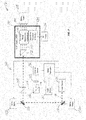
Block 71, themulti-channel system 130 illustratively includes alaser source 131 which generates a firstlaser light beam 141, atBlock 72. Thelaser source 131 may be similar to the laser source 31 described above. A diffractive/refractive beam splitter 142 divides the firstlaser light beam 141 into a plurality of second laser light beams 143, atBlock 73, which in the illustrated example is four, although other numbers of beams (e.g., 8, 32, etc.) may be used depending upon the given application. The second laser light beams 143 are received by a common phase modulation acousto-optic medium 133 of amulti-channel AOM 132. That is, the acousto-optic medium 133 is common to all of the second laser light beams, i.e., the same acousto-optic medium is used to modulate each of the second laser light beams. The acousto-optic medium 133 may be similar to those described above. However, it should be noted that the phase-capablemulti-channel AOM 132 need not be used, and that an amplitude modulation AOM may instead by used, for example. - The
AOM 132 further includes multiple transducers, each comprisingrespective electrodes 134, for each of the second laser light beams 143 coupled to the common acousto-optic medium 133. Thelaser system 130 further illustratively includes a plurality ofRF drivers 136 each configured to generate the requisite RF drive signals for their respective phasedarray transducer electrodes 134, atBlock 74, which illustratively concludes the method ofFIG. 7 (Block 75). - Referring additionally to
FIGS. 3 and 4 , eachRF driver 136 may be configured to drive alternating electrodes of the respective array oftransducer electrodes 134 with different phases. More particularly, two example configurations for driving alternatingelectrodes 40 of the array oftransducer electrodes 34 with different phases are now described. In the first configuration (FIG. 3 ), the first and third driving signals (shown on the right hand side ofFIG. 3 ) provided to corresponding odd numbered electrodes are 180º out of phase with the second and fourth driving signals provided to corresponding even numbered electrodes. In the second configuration (FIG. 4 ), first and second drive signals are respectively connected to odd and even electrodes in an interdigitated fashion as shown, and as before these drive signals are 180º out of phase to one another. In this way, directly adjacent electrodes are driven at opposite phases to one another. However, it should be noted that the RF drive signals need not always be 180° out of phase, i.e., they may be somewhere between 0º and 180º to vary the level of phase matching occurring in the AO diffraction process. - Such a bi-phase configuration helps to eliminate beam deflection due to thermal transients generated when channel data is switched on and off, i.e., by using phase modulation only. More particularly, a bi-phase approach maintains the RF Signal "ON" and only flips the phase of the drive signal to alternating elements, as opposed to a conventional amplitude modulation approach in which optical modulation is achieved by turning the RF signal "ON" and "OFF".
- The present approach may accordingly reduce time average thermal gradients produced by the aggregate array during normal operation since the RF power level is essentially constant or stationary, which helps to minimize polarization corruption and gross beam offset. This further helps to reduce beam intensity fluctuations produced by inter-channel acoustic crosstalk by minimizing changes in the adjacent channel strain field due to changes in local channel data.
- By way of example, the
transducer electrodes 134 may be implemented as metalizations on the piezoelectric AO medium 133, which are spaced apart 500 µm or less at their centers, and more particularly 450 µm or less. However, other dimensions may be used in different embodiments. - Accordingly, employing a phase modulation capable acousto-optic modulator or transducer structure in a multi-channel device configuration provides significant advantages. More particularly, phase modulation used with pulse code (ON/OFF) modulation provides inherently better pointing stability, since the RF power applied to the device remains substantially constant at all times, even during data input bit transitions. Moreover, the effects of inter-channel acoustic crosstalk are reduced since the integrated optical effect resulting from changes in the localized strain field due to adjacent transducer operation are reduced. This technique may be particularly appropriate when reduced "ON/OFF" contrast is acceptable, e.g., mask generation involving photoresist. However, in addition to a photoresist layer of a semiconductor device, other
optical targets 138 may also be used with thesystem 130, such as an ion trap(s), micromachining workpiece, etc. - Turning now to
FIG. 2 and the flow diagram 80 ofFIG. 6 , amulti-channel laser system 230 which may incorporate themulti-channel AOM 132 described above, or alternately an array of conventional transducers, for quantum state applications is now described. By way of background, quantum state manipulation illumination systems control both the optical amplitude and phase in an interferometric application. However, this requires significant improvements in crosstalk and beam pointing stability. - Beginning at
Block 81, thesystem 230 illustratively includes a laser source 231, such as those described above, which is configured to generate a laser light beam (Block 82). The output of the laser source 231 may optionally be provided to a single channelamplitude leveling AOM 251, which helps reduce noise from the laser source. The output of theAOM 251 is split into a first front sidelaser light beam 252 and a back sidelaser light beam 253 for a back side of anion trap 238 by abeamsplitter 260, atBlock 83. The front sidelaser light beam 252 passes through aninput telescope 245 to themulti-channel AOM 132, atBlock 84. As noted above, theAOM 132 includes the diffractive/refractive beamsplitter 142 or diffractive optical element (DOE) to split the front sidelaser light beam 252 into a plurality of front side laser light beams 246, atBlock 85. In the illustrated example, four such beams are shown, but in other embodiments different numbers of beams may be used, as noted above. Additional beam forming optics between thebeamsplitter 142 and the common AO medium 133 are incorporated to allow telecentric beam positioning and adjustment of individual beam waist dimensions along the centerline and midpoint of each transducer. - The modulated front side laser light beams 254 output by the
AOM 132 are passed through anoutput telescope 247 and directed to the front side of anion trap 238, atBlock 86. The back sidelaser light beam 253 is directed to afirst turning mirror 255, and then through first and second focusingoptics 256, 257 (although different numbers of optical focusing stages may be used in different embodiments) to asingle channel AOM 258. The output of thesingle channel AOM 258 is directed by turningmirrors ion trap 238 in the example implementation. Furthermore, respective RF drive signals are generated for the phasedarray transducer electrodes 134 using the plurality ofRF drivers 136, atBlock 87, as similarly described above, or using simplified drive signals when conventional transducers are employed. The method ofFIG. 6 illustratively concludes atBlock 88. - In accordance with one example implementation, an integrated
multi-channel AOM assembly 132 may be provided including a high efficiency DOE orbeamsplitter 142, a set of telecentric beam forming optics, a thermally compensated N channel AOM including the common AO medium 133 and in one embodiment transducers employing an array of phasedelectrodes 134, and in certain applications, a counter propagating illumination beam. As noted above, the input beam may be split into N separate optical beams, each of which may be independently modulated in phase and amplitude, with a frequency shift on the first order diffracted beam equal to the acoustic frequency. The resultant individual beam pointing stability is not only suitable for precision photolithography tools, but also addressing applications such as illuminating atoms in an ion trap architecture quantum computer, micro-machining and 3D printing, for example. - A highly engineered integrated module approach may be used to achieve the highly uniform, stable, low cross-talk multi-channel beam illumination system needed for high precision manipulation of quantum states of individual atoms. This integrated module approach may be used at various interaction wavelengths. It should be noted that the noise diverting approach using the first order beam as a noise dump described above with respect to
FIG. 1 may also be employed in thesystems - In one or more of the foregoing embodiments, separate active heating elements may be included to help improve performance, if desired. One such configuration is set forth in
U.S. Pat. No. 6,765,709 to Montgomery et al. , which is assigned to the present Assignee. Furthermore, additional techniques may also be employed for noise reduction in some embodiments, such as described inUS 2018120599 andUS2018120600 . - Turning now to
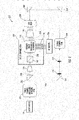
FIG. 7 , another example implementation of thelaser system 130 illustratively includes abeam stabilizer 150 to help address "wandering" of the laser light beam from thelaser source 131. In the present example, thebeam stabilizer 150 is configured to correct an angular displacement and a positional displacement of thelaser light beam 141 from the laser source 131 (although both positional and angular displacement need not be corrected in all embodiments). More particularly, thebeam stabilizer 150 illustratively includes aposition mirror 151 optically aligned with thelaser light beam 141 from thelaser source 131, aservo motor 152a configured to move the position mirror, anangle mirror 153 optically aligned with the position mirror to redirect the laser light beam therefrom to themulti-channel AOM 132, and aservo motor 152b configured to move the angle mirror. - Furthermore, a
beamsplitter 154 is positioned in the optical path between theangle mirror 153 and themulti-channel AOM 132 downstream from the angle mirror and configured to split a sampledlaser light beam 155 from the originallaser light beam 141 from thelaser source 131, and direct this sampled laser light beam to anangle sensor 157. Furthermore, in the illustrated example anotherbeamsplitter 156 is positioned in the optical path of the sampledlaser light beam 155 between thebeamsplitter 154 and theangle sensor 157 to split off another sampledlaser light beam 158 which is directed through alens 159 to image theangle mirror 153 to aposition sensor 180. Theangle sensor 157 is configured to measure an angular displacement of thelaser light beam 141 from thelaser source 131, and theposition sensor 180 is configured to measure a positional displacement of the laser light beam from the laser source. These measurements are provided to aservo controller 181, which in turn controls or actuates theservo motors laser source 131. - Turning now to
FIG. 8 , in accordance with another example embodiment thebeam stabilizer 150 may also be incorporated in thelaser system 230. In this configuration, theposition mirror 151 is optically aligned with the laser light beam from thelaser source 131, theservo motor 152a is configured to move the position mirror, theangle mirror 153 is optically aligned with the position mirror to redirect the laser light beam therefrom to thesingle channel AOM 251, and theservo motor 152b is configured to move the angle mirror. - Furthermore, the
beamsplitter 154 is positioned in the optical path between theangle mirror 153 and thesingle channel AOM 251 downstream from the angle mirror and is configured to split the sampledlaser light beam 155 from the originallaser light beam 141 from thelaser source 131, and direct this sampled laser light beam to theangle sensor 157. Furthermore, thebeamsplitter 156 is positioned in the optical path of the sampledlaser light beam 155 between thebeamsplitter 154 and theangle sensor 157 to split off another sampledlaser light beam 158 which is directed through thelens 159 to image theangle mirror 153 to theposition sensor 180. Theangle sensor 157 is configured to measure an angular displacement of the laser light beam from thelaser source 131, and theposition sensor 180 is configured to measure a positional displacement of the laser light beam from the laser source. These measurements are provided to theservo controller 181, which in turn controls or actuates theservo motors laser light beam 141 at thelaser source 131. - Referring additionally to
FIG. 9 , still another example implementation of the laser system 230' is now described in which portions of the beam stabilizer 150' are positioned both upstream and downstream from the AOM 251', rather than all upstream as in thesystem 230. In this example, the position mirror 151' and angle mirror 153' remain upstream from the AOM 251', but the beamsplitters 154', 156', angle sensor 157', and position sensor 180' are downstream of the AOM, meaning they are splitting/measuring the beam exiting the AOM, as opposed to the laser light beam 141' from the laser source 131' as in thesystem 230. Nevertheless, the servo controller 181' still causes theservo motors 152a', 152b' to adjust the position mirror 151' and angle mirror 153' to perform beam correction to the laser light beam 141' exiting the laser source 131' as noted above. - Turning now to
FIG. 10 , still another example implementation of thesystem 230" with abeam stabilizer 150" is now described. In this embodiment, thebeam stabilizer 150" is downstream from theAOM 251", including theposition mirror 151" and theangle mirror 153". As such, themirrors 151", 153" are directing, and thebeamsplitters 154", 155",angle sensor 157", andposition sensor 180", are splitting/measuring, the beam exiting theAOM 251". Moreover, the corrections performed by the servo motor(s) 152" andposition mirror 151" are to the beam exiting theAOM 251", not thelaser light beam 141" from thelaser source 131" as in the preceding two embodiments. - It should be noted that of the
systems laser system 230 shown inFIG. 2 are not reproduced inFIGS. 8-10 for clarity of illustration of the components of thebeam stabilizers - Related method aspects corresponding to the
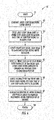
system 130 ofFIG. 7 are now described with reference to the flow diagram 370 ofFIG. 11 . Beginning atBlock 371, the method illustratively includes generating a firstlaser light beam 141 using alaser source 131, atBlock 372, and stabilizing the first laser light beam using abeam stabilizer 150 downstream from the laser source, atBlock 373. The method further illustratively includes splitting the stabilizedfirst laser light 141 beam into a plurality of second laser light beams 143 using abeamsplitter 142 downstream from thebeam stabilizer 150, atBlock 374, and receiving the plurality of second laser light beams at a common acousto-optic medium 133, atBlock 375. The method also illustratively includes generating respective RF drive signals for a plurality of phasedarray transducer electrodes 134 coupled to the common acousto-optic medium 133 for each of the second laser light beams 143 using a plurality ofRF drivers 136, atBlock 376, which illustratively concludes the method ofFIG. 11 (Block 377). - Additional method aspects corresponding to the
systems 230, 230' ofFIGS. 8 and9 are now described with reference to the flow diagram 380 ofFIG. 12 . The method begins (Block 380) with generating alaser 141, 141' light beam using alaser source 131, 131', atBlock 382, stabilizing the laser light beam using abeam stabilizer 150, 150' downstream from the laser source, and splitting the laser light beam using afirst beamsplitter 260, 260' into a first front sidelaser light beam 252 and a back sidelaser light beam 253 for a back side of an ion trap 238 (seeFIG. 2 ), atBlock 384. The method further illustratively includes directing the front sidelaser light beam 252 to asecond beamsplitter 142 using aninput telescope 245, atBlock 385, splitting the first front sidelaser light beam 252 using the second beamsplitter into a plurality of second front side laser light beams 246 from the second beamsplitter, atBlock 386, and receiving the plurality of front side laser light beams at a common acousto-optic medium 133 (Block 387). Furthermore, the method also illustratively includes generating respective RF drive signals for each of a respective plurality ofelectrodes 134 coupled to the common acousto-optic medium for each of the second front side laser light beams 246 using a plurality ofRF drivers 136, atBlock 388, and directing the plurality of second front side laser light beams 254 output from the common acousto-optic medium 133 to a front side of theion trap 238 using anoutput telescope 247, atBlock 389, which illustratively concludes the method ofFIG. 12 (Block 390). - Turning now to the flow diagram 400 of
FIG. 13 , method aspects relating to thesystem 230" are now described. Beginning atBlock 381, the method illustratively includes generating alaser light beam 141" using alaser source 131", atBlock 402, modulating the laser light beam from the laser source using the single channelamplitude leveling AOM 251" to provide an output light beam, atBlock 403, and stabilizing the output light beam using abeam stabilizer 150" downstream from the single channel AOM, atBlock 404. The remaining steps illustrated at Blocks 406-411 are similar to those described above with reference to Blocks 385-390 ofFIG. 12 , and accordingly require no further discussion herein. - It should also be noted that in some embodiments of the system 130 a single channel
amplitude leveling AOM 251 may also be incorporated between thelaser source 131 and themulti-channel AOM 132, if desired. In such cases, thebeam stabilizer 150 may be configured as shown inFIGS. 8 ,9 , or10 , for example. - Further beam stabilization aspects and techniques for laser systems are discussed in
US 2018 173027 - Many modifications and other embodiments will come to the mind of one skilled in the art having the benefit of the teachings presented in the foregoing descriptions and the associated drawings. Therefore, it is understood that the disclosure is not to be limited to the specific embodiments disclosed, and that modifications and embodiments are intended to be included within the scope of the appended claims.
Claims (8)
- A laser system (130) for illuminating an optical target (138) comprising:a laser source (131) configured to generate a first laser light beam (141);a beam stabilizer (150) downstream from the laser source and configured to stabilize the first laser light beam;a beamsplitter (142) downstream from the beam stabilizer and configured to split the stabilized first laser light beam into a plurality of second laser light beams (143);a multi-channel acousto-optic modulator, AOM, (132) comprisinga common acousto-optic medium (133) configured to receive the plurality of second laser light beams, anda respective phase array transducer (134) comprising a plurality of electrodes coupled to the common acousto-optic medium for each of the second laser light beams; anda plurality of radio frequency, RF, drivers (136) each configured to generate respective RF drive signals for the phased array transducer electrodes;characterized in that the beam stabilizer (150) comprises:a position mirror (151) optically aligned with the first laser light beam (141) from the laser source (131);a first servo motor (152a) configured to move the position mirror;a position sensor (180) configured to measure a positional displacement of the laser light beam; andan angle mirror (153) optically aligned with the first laser light beam (141) from the laser source (131);a second servo motor (152b) configured to move the angle mirror;an angle sensor (157) configured to measure an angular displacement of the laser light beam; anda servo controller (181) coupled to the servo motors (152a, 152b) and configured to actuate the first servo motor (152a) to stabilize the first laser light beam based upon the position sensor and configured to actuate the second servo motor (152b) to stabilize the first laser light beam based upon the angle sensor.
- The laser system (130) of Claim 1 wherein the beam stabilizer (150) is configured to correct a positional displacement of the laser light beam.
- The laser system (130) of Claim 1 wherein the beam stabilizer (150) is configured to correct an angular displacement of the laser light beam (141).
- The laser system of Claim 1 wherein each RF driver (136) is configured to drive alternating electrodes of the respective phased array transducer (134) electrodes with different phases.
- A method (370) for illuminating an optical target (138) comprising:generating (372) a first laser light beam using a laser source;stabilizing (373) the first laser light beam using a beam stabilizer (150) downstream from the laser source;splitting (374) the stabilized first laser light beam into a plurality of second laser light beams using a beamsplitter downstream from the beam stabilizer;receiving (375) the plurality of second laser light beams at a common acousto-optic medium; andgenerating (376) respective radio frequency, RF, drive signals for a plurality of phased array transducer electrodes coupled to the common acousto-optic medium for each of the second laser light beams using a plurality of RF drivers;wherein the method is characterized in that the beam stabilizer (150) comprises:a position mirror (151) optically aligned with the first laser light beam (141) from the laser source (131);a first servo motor (152a) configured to move the position mirror;a position sensor (180) configured to measure a positional displacement of the laser light beam; andan angle mirror (153) optically aligned with the first laser light beam (141) from the laser source (131);a second servo motor (152b) configured to move the angle mirror;an angle sensor (157) configured to measure an angular displacement of the laser light beam; and a servo controller (181) coupled to the servo motors (152a, 152b) and configured to actuate the first servo motor (152a) to stabilize the first laser light beam based upon the position sensor and configured to actuate the second servo motor (152b) to stabilize the first laser light beam based upon the angle sensor.
- The method (370) of Claim 5 wherein the beam stabilizer is configured to correct a positional displacement of the laser light beam.
- The method (370) of Claim 5 wherein the beam stabilizer is configured to correct an angular displacement of the laser light beam.
- The method (370) of Claim 5 wherein generating comprises generating the RF drive signals to drive alternating electrodes of the respective phased array transducer electrodes with different phases.
Applications Claiming Priority (1)
| Application Number | Priority Date | Filing Date | Title |
|---|---|---|---|
| US15/918,217 US10495943B2 (en) | 2016-11-03 | 2018-03-12 | Multi-channel phase-capable acousto-optic modulator (AOM) including beam stabilizer and related methods |
Publications (2)
| Publication Number | Publication Date |
|---|---|
| EP3540500A1 EP3540500A1 (en) | 2019-09-18 |
| EP3540500B1 true EP3540500B1 (en) | 2021-04-07 |
Family
ID=65628573
Family Applications (1)
| Application Number | Title | Priority Date | Filing Date |
|---|---|---|---|
| EP19159311.0A Active EP3540500B1 (en) | 2018-03-12 | 2019-02-26 | Multi-channel phase-capable acousto-optic modulator (aom) including beam stabilizer and related methods |
Country Status (1)
| Country | Link |
|---|---|
| EP (1) | EP3540500B1 (en) |
Family Cites Families (11)
| Publication number | Priority date | Publication date | Assignee | Title |
|---|---|---|---|---|
| US4256362A (en) | 1978-01-31 | 1981-03-17 | Harris Corporation | Phase-insensitive hologram readout technique |
| US5576880A (en) * | 1994-03-31 | 1996-11-19 | Aurora Photonics, Inc. | Acousto-optic bragg cell |
| US5689331A (en) * | 1995-12-08 | 1997-11-18 | General Electric Company | Laser apparatus with wander correction |
| US5923460A (en) | 1998-05-19 | 1999-07-13 | Harris Corporation | Mechanism for extending instantaneous RF frequency coverage for an acousto-optic coherent channel receiver (AOCCR) via bandwidth dilation |
| US6320989B1 (en) | 1999-01-22 | 2001-11-20 | Harris Corporation | Stepped acoustic impedance-matching transformer for very narrow channel acoustic traveling wave lens waveguide |
| US6538690B1 (en) | 2000-03-08 | 2003-03-25 | Harris Corporation | Timing control in acousto-optic scanner based on acoustic velocity of traveling wave lens |
| US6765709B1 (en) | 2003-04-28 | 2004-07-20 | Harris Corporation | Active compensation for transient thermal effects in acousto-optic devices |
| US6870658B2 (en) | 2003-06-16 | 2005-03-22 | Harris Corporation | Energy limiter for amplitude modulated RF waveforms |
| JP4729269B2 (en) * | 2004-06-01 | 2011-07-20 | オリンパス株式会社 | Laser scanning microscope |
| US7538929B2 (en) | 2007-04-06 | 2009-05-26 | Harris Corporation | RF phase modulation technique for performing acousto-optic intensity modulation of an optical wavefront |
| US8958052B2 (en) * | 2010-11-04 | 2015-02-17 | Micronic Ab | Multi-method and device with an advanced acousto-optic deflector (AOD) and a dense brush of flying spots |
-
2019
- 2019-02-26 EP EP19159311.0A patent/EP3540500B1/en active Active
Non-Patent Citations (1)
| Title |
|---|
| None * |
Also Published As
| Publication number | Publication date |
|---|---|
| EP3540500A1 (en) | 2019-09-18 |
Similar Documents
| Publication | Publication Date | Title |
|---|---|---|
| US10495943B2 (en) | Multi-channel phase-capable acousto-optic modulator (AOM) including beam stabilizer and related methods | |
| US10754223B2 (en) | Multi-channel laser system including an acoustic-optic modulator (AOM) with atom trap and related methods | |
| US10509245B2 (en) | Multi-channel laser system including an acousto-optic modulator (AOM) with beam stabilizer and related methods | |
| US9958710B1 (en) | Multi-channel laser system including an acousto-optic modulator (AOM) and related methods | |
| US10466516B2 (en) | Control system including a beam stabilizer and a phase modulation capable acousto-optic modulator for diverting laser output intensity noise to a first order laser light beam and related methods | |
| EP3319185B1 (en) | Multi-channel phase-capable acousto-optic modulator (aom) and related methods | |
| JP6013566B2 (en) | Laser output beam wavefront splitter for bandwidth spectrum control | |
| EP3540501B1 (en) | Multi-channel laser system including an acousto-optic modulator (aom) with beam stabilizer and related methods | |
| US9958711B1 (en) | Control system using a phase modulation capable acousto-optic modulator for diverting laser output intensity noise to a first order laser light beam and related methods | |
| JP2006196638A (en) | Laser oscillation control method of pulse laser, and pulse laser system | |
| EP3627213B1 (en) | Multi-channel laser system including an acousto-optic modulator (aom) with beam polarization switching and related methods | |
| CN111133361B (en) | Acousto-optic system with phase-shifting reflector | |
| EP3540500B1 (en) | Multi-channel phase-capable acousto-optic modulator (aom) including beam stabilizer and related methods | |
| US11960156B2 (en) | Multi-channel laser system including an acousto-optic modulator (AOM) with beam polarization switching and related methods | |
| US11327348B2 (en) | Multi-channel laser system including optical assembly with etched optical signal channels and related methods | |
| EP3531197B1 (en) | Control system including a beam stabilizer and a phase modulation capable acousto-optic modulator for diverting laser output intensity noise to a first order laser light beam and related methods | |
| US5362956A (en) | Piston error sensor for phased optical arrays | |
| US7911160B2 (en) | Oscillation device, optical deflection apparatus, and drive-signal generating method | |
| JP2004291010A (en) | Device and method for laser beam machining |
Legal Events
| Date | Code | Title | Description |
|---|---|---|---|
| PUAI | Public reference made under article 153(3) epc to a published international application that has entered the european phase |
Free format text: ORIGINAL CODE: 0009012 |
|
| STAA | Information on the status of an ep patent application or granted ep patent |
Free format text: STATUS: REQUEST FOR EXAMINATION WAS MADE |
|
| 17P | Request for examination filed |
Effective date: 20190226 |
|
| AK | Designated contracting states |
Kind code of ref document: A1 Designated state(s): AL AT BE BG CH CY CZ DE DK EE ES FI FR GB GR HR HU IE IS IT LI LT LU LV MC MK MT NL NO PL PT RO RS SE SI SK SM TR |
|
| AX | Request for extension of the european patent |
Extension state: BA ME |
|
| RAP1 | Party data changed (applicant data changed or rights of an application transferred) |
Owner name: HARRIS CORPORATION |
|
| STAA | Information on the status of an ep patent application or granted ep patent |
Free format text: STATUS: EXAMINATION IS IN PROGRESS |
|
| 17Q | First examination report despatched |
Effective date: 20200708 |
|
| GRAP | Despatch of communication of intention to grant a patent |
Free format text: ORIGINAL CODE: EPIDOSNIGR1 |
|
| STAA | Information on the status of an ep patent application or granted ep patent |
Free format text: STATUS: GRANT OF PATENT IS INTENDED |
|
| INTG | Intention to grant announced |
Effective date: 20210113 |
|
| GRAS | Grant fee paid |
Free format text: ORIGINAL CODE: EPIDOSNIGR3 |
|
| GRAA | (expected) grant |
Free format text: ORIGINAL CODE: 0009210 |
|
| STAA | Information on the status of an ep patent application or granted ep patent |
Free format text: STATUS: THE PATENT HAS BEEN GRANTED |
|
| AK | Designated contracting states |
Kind code of ref document: B1 Designated state(s): AL AT BE BG CH CY CZ DE DK EE ES FI FR GB GR HR HU IE IS IT LI LT LU LV MC MK MT NL NO PL PT RO RS SE SI SK SM TR |
|
| REG | Reference to a national code |
Ref country code: GB Ref legal event code: FG4D |
|
| REG | Reference to a national code |
Ref country code: AT Ref legal event code: REF Ref document number: 1380452 Country of ref document: AT Kind code of ref document: T Effective date: 20210415 Ref country code: CH Ref legal event code: EP |
|
| REG | Reference to a national code |
Ref country code: DE Ref legal event code: R096 Ref document number: 602019003665 Country of ref document: DE |
|
| REG | Reference to a national code |
Ref country code: IE Ref legal event code: FG4D |
|
| REG | Reference to a national code |
Ref country code: LT Ref legal event code: MG9D |
|
| REG | Reference to a national code |
Ref country code: NL Ref legal event code: MP Effective date: 20210407 Ref country code: AT Ref legal event code: MK05 Ref document number: 1380452 Country of ref document: AT Kind code of ref document: T Effective date: 20210407 |
|
| PG25 | Lapsed in a contracting state [announced via postgrant information from national office to epo] |
Ref country code: NL Free format text: LAPSE BECAUSE OF FAILURE TO SUBMIT A TRANSLATION OF THE DESCRIPTION OR TO PAY THE FEE WITHIN THE PRESCRIBED TIME-LIMIT Effective date: 20210407 Ref country code: BG Free format text: LAPSE BECAUSE OF FAILURE TO SUBMIT A TRANSLATION OF THE DESCRIPTION OR TO PAY THE FEE WITHIN THE PRESCRIBED TIME-LIMIT Effective date: 20210707 Ref country code: AT Free format text: LAPSE BECAUSE OF FAILURE TO SUBMIT A TRANSLATION OF THE DESCRIPTION OR TO PAY THE FEE WITHIN THE PRESCRIBED TIME-LIMIT Effective date: 20210407 Ref country code: LT Free format text: LAPSE BECAUSE OF FAILURE TO SUBMIT A TRANSLATION OF THE DESCRIPTION OR TO PAY THE FEE WITHIN THE PRESCRIBED TIME-LIMIT Effective date: 20210407 Ref country code: HR Free format text: LAPSE BECAUSE OF FAILURE TO SUBMIT A TRANSLATION OF THE DESCRIPTION OR TO PAY THE FEE WITHIN THE PRESCRIBED TIME-LIMIT Effective date: 20210407 Ref country code: FI Free format text: LAPSE BECAUSE OF FAILURE TO SUBMIT A TRANSLATION OF THE DESCRIPTION OR TO PAY THE FEE WITHIN THE PRESCRIBED TIME-LIMIT Effective date: 20210407 |
|
| PG25 | Lapsed in a contracting state [announced via postgrant information from national office to epo] |
Ref country code: RS Free format text: LAPSE BECAUSE OF FAILURE TO SUBMIT A TRANSLATION OF THE DESCRIPTION OR TO PAY THE FEE WITHIN THE PRESCRIBED TIME-LIMIT Effective date: 20210407 Ref country code: SE Free format text: LAPSE BECAUSE OF FAILURE TO SUBMIT A TRANSLATION OF THE DESCRIPTION OR TO PAY THE FEE WITHIN THE PRESCRIBED TIME-LIMIT Effective date: 20210407 Ref country code: PT Free format text: LAPSE BECAUSE OF FAILURE TO SUBMIT A TRANSLATION OF THE DESCRIPTION OR TO PAY THE FEE WITHIN THE PRESCRIBED TIME-LIMIT Effective date: 20210809 Ref country code: NO Free format text: LAPSE BECAUSE OF FAILURE TO SUBMIT A TRANSLATION OF THE DESCRIPTION OR TO PAY THE FEE WITHIN THE PRESCRIBED TIME-LIMIT Effective date: 20210707 Ref country code: LV Free format text: LAPSE BECAUSE OF FAILURE TO SUBMIT A TRANSLATION OF THE DESCRIPTION OR TO PAY THE FEE WITHIN THE PRESCRIBED TIME-LIMIT Effective date: 20210407 Ref country code: PL Free format text: LAPSE BECAUSE OF FAILURE TO SUBMIT A TRANSLATION OF THE DESCRIPTION OR TO PAY THE FEE WITHIN THE PRESCRIBED TIME-LIMIT Effective date: 20210407 Ref country code: GR Free format text: LAPSE BECAUSE OF FAILURE TO SUBMIT A TRANSLATION OF THE DESCRIPTION OR TO PAY THE FEE WITHIN THE PRESCRIBED TIME-LIMIT Effective date: 20210708 Ref country code: IS Free format text: LAPSE BECAUSE OF FAILURE TO SUBMIT A TRANSLATION OF THE DESCRIPTION OR TO PAY THE FEE WITHIN THE PRESCRIBED TIME-LIMIT Effective date: 20210807 |
|
| REG | Reference to a national code |
Ref country code: DE Ref legal event code: R097 Ref document number: 602019003665 Country of ref document: DE |
|
| PG25 | Lapsed in a contracting state [announced via postgrant information from national office to epo] |
Ref country code: SK Free format text: LAPSE BECAUSE OF FAILURE TO SUBMIT A TRANSLATION OF THE DESCRIPTION OR TO PAY THE FEE WITHIN THE PRESCRIBED TIME-LIMIT Effective date: 20210407 Ref country code: ES Free format text: LAPSE BECAUSE OF FAILURE TO SUBMIT A TRANSLATION OF THE DESCRIPTION OR TO PAY THE FEE WITHIN THE PRESCRIBED TIME-LIMIT Effective date: 20210407 Ref country code: EE Free format text: LAPSE BECAUSE OF FAILURE TO SUBMIT A TRANSLATION OF THE DESCRIPTION OR TO PAY THE FEE WITHIN THE PRESCRIBED TIME-LIMIT Effective date: 20210407 Ref country code: SM Free format text: LAPSE BECAUSE OF FAILURE TO SUBMIT A TRANSLATION OF THE DESCRIPTION OR TO PAY THE FEE WITHIN THE PRESCRIBED TIME-LIMIT Effective date: 20210407 Ref country code: RO Free format text: LAPSE BECAUSE OF FAILURE TO SUBMIT A TRANSLATION OF THE DESCRIPTION OR TO PAY THE FEE WITHIN THE PRESCRIBED TIME-LIMIT Effective date: 20210407 Ref country code: CZ Free format text: LAPSE BECAUSE OF FAILURE TO SUBMIT A TRANSLATION OF THE DESCRIPTION OR TO PAY THE FEE WITHIN THE PRESCRIBED TIME-LIMIT Effective date: 20210407 Ref country code: DK Free format text: LAPSE BECAUSE OF FAILURE TO SUBMIT A TRANSLATION OF THE DESCRIPTION OR TO PAY THE FEE WITHIN THE PRESCRIBED TIME-LIMIT Effective date: 20210407 |
|
| PLBE | No opposition filed within time limit |
Free format text: ORIGINAL CODE: 0009261 |
|
| STAA | Information on the status of an ep patent application or granted ep patent |
Free format text: STATUS: NO OPPOSITION FILED WITHIN TIME LIMIT |
|
| 26N | No opposition filed |
Effective date: 20220110 |
|
| PG25 | Lapsed in a contracting state [announced via postgrant information from national office to epo] |
Ref country code: IS Free format text: LAPSE BECAUSE OF FAILURE TO SUBMIT A TRANSLATION OF THE DESCRIPTION OR TO PAY THE FEE WITHIN THE PRESCRIBED TIME-LIMIT Effective date: 20210807 Ref country code: AL Free format text: LAPSE BECAUSE OF FAILURE TO SUBMIT A TRANSLATION OF THE DESCRIPTION OR TO PAY THE FEE WITHIN THE PRESCRIBED TIME-LIMIT Effective date: 20210407 |
|
| PG25 | Lapsed in a contracting state [announced via postgrant information from national office to epo] |
Ref country code: IT Free format text: LAPSE BECAUSE OF FAILURE TO SUBMIT A TRANSLATION OF THE DESCRIPTION OR TO PAY THE FEE WITHIN THE PRESCRIBED TIME-LIMIT Effective date: 20210407 |
|
| PG25 | Lapsed in a contracting state [announced via postgrant information from national office to epo] |
Ref country code: MC Free format text: LAPSE BECAUSE OF FAILURE TO SUBMIT A TRANSLATION OF THE DESCRIPTION OR TO PAY THE FEE WITHIN THE PRESCRIBED TIME-LIMIT Effective date: 20210407 |
|
| REG | Reference to a national code |
Ref country code: CH Ref legal event code: PL |
|
| REG | Reference to a national code |
Ref country code: BE Ref legal event code: MM Effective date: 20220228 |
|
| PG25 | Lapsed in a contracting state [announced via postgrant information from national office to epo] |
Ref country code: LU Free format text: LAPSE BECAUSE OF NON-PAYMENT OF DUE FEES Effective date: 20220226 |
|
| PG25 | Lapsed in a contracting state [announced via postgrant information from national office to epo] |
Ref country code: FR Free format text: LAPSE BECAUSE OF NON-PAYMENT OF DUE FEES Effective date: 20220228 |
|
| PG25 | Lapsed in a contracting state [announced via postgrant information from national office to epo] |
Ref country code: LI Free format text: LAPSE BECAUSE OF NON-PAYMENT OF DUE FEES Effective date: 20220228 Ref country code: IE Free format text: LAPSE BECAUSE OF NON-PAYMENT OF DUE FEES Effective date: 20220226 Ref country code: CH Free format text: LAPSE BECAUSE OF NON-PAYMENT OF DUE FEES Effective date: 20220228 |
|
| PG25 | Lapsed in a contracting state [announced via postgrant information from national office to epo] |
Ref country code: BE Free format text: LAPSE BECAUSE OF NON-PAYMENT OF DUE FEES Effective date: 20220228 |
|
| PGFP | Annual fee paid to national office [announced via postgrant information from national office to epo] |
Ref country code: GB Payment date: 20230227 Year of fee payment: 5 Ref country code: DE Payment date: 20230223 Year of fee payment: 5 |
|
| P01 | Opt-out of the competence of the unified patent court (upc) registered |
Effective date: 20230525 |