EP3540461B1 - Systems and methods for determining a position of a transmitter of a bistatic radar system - Google Patents
Systems and methods for determining a position of a transmitter of a bistatic radar system Download PDFInfo
- Publication number
- EP3540461B1 EP3540461B1 EP19173090.2A EP19173090A EP3540461B1 EP 3540461 B1 EP3540461 B1 EP 3540461B1 EP 19173090 A EP19173090 A EP 19173090A EP 3540461 B1 EP3540461 B1 EP 3540461B1
- Authority
- EP
- European Patent Office
- Prior art keywords
- transmitter
- receiver
- target
- determination unit
- bistatic
- Prior art date
- Legal status (The legal status is an assumption and is not a legal conclusion. Google has not performed a legal analysis and makes no representation as to the accuracy of the status listed.)
- Active
Links
- 238000000034 method Methods 0.000 title claims description 32
- 238000010586 diagram Methods 0.000 description 22
- 238000004891 communication Methods 0.000 description 11
- 230000006870 function Effects 0.000 description 5
- 230000004044 response Effects 0.000 description 5
- 238000009987 spinning Methods 0.000 description 4
- XLYOFNOQVPJJNP-UHFFFAOYSA-N water Substances O XLYOFNOQVPJJNP-UHFFFAOYSA-N 0.000 description 4
- 230000005855 radiation Effects 0.000 description 3
- 230000001427 coherent effect Effects 0.000 description 2
- 238000004590 computer program Methods 0.000 description 2
- 230000001419 dependent effect Effects 0.000 description 2
- 238000001514 detection method Methods 0.000 description 2
- PEDCQBHIVMGVHV-UHFFFAOYSA-N Glycerine Chemical compound OCC(O)CO PEDCQBHIVMGVHV-UHFFFAOYSA-N 0.000 description 1
- 238000004364 calculation method Methods 0.000 description 1
- 230000001934 delay Effects 0.000 description 1
- 230000009365 direct transmission Effects 0.000 description 1
- 238000009472 formulation Methods 0.000 description 1
- 230000007257 malfunction Effects 0.000 description 1
- 239000011159 matrix material Substances 0.000 description 1
- 238000005259 measurement Methods 0.000 description 1
- 239000000203 mixture Substances 0.000 description 1
- 230000000007 visual effect Effects 0.000 description 1
Images

Classifications
-
- G—PHYSICS
- G01—MEASURING; TESTING
- G01S—RADIO DIRECTION-FINDING; RADIO NAVIGATION; DETERMINING DISTANCE OR VELOCITY BY USE OF RADIO WAVES; LOCATING OR PRESENCE-DETECTING BY USE OF THE REFLECTION OR RERADIATION OF RADIO WAVES; ANALOGOUS ARRANGEMENTS USING OTHER WAVES
- G01S5/00—Position-fixing by co-ordinating two or more direction or position line determinations; Position-fixing by co-ordinating two or more distance determinations
- G01S5/02—Position-fixing by co-ordinating two or more direction or position line determinations; Position-fixing by co-ordinating two or more distance determinations using radio waves
- G01S5/0273—Position-fixing by co-ordinating two or more direction or position line determinations; Position-fixing by co-ordinating two or more distance determinations using radio waves using multipath or indirect path propagation signals in position determination
-
- G—PHYSICS
- G01—MEASURING; TESTING
- G01S—RADIO DIRECTION-FINDING; RADIO NAVIGATION; DETERMINING DISTANCE OR VELOCITY BY USE OF RADIO WAVES; LOCATING OR PRESENCE-DETECTING BY USE OF THE REFLECTION OR RERADIATION OF RADIO WAVES; ANALOGOUS ARRANGEMENTS USING OTHER WAVES
- G01S5/00—Position-fixing by co-ordinating two or more direction or position line determinations; Position-fixing by co-ordinating two or more distance determinations
- G01S5/02—Position-fixing by co-ordinating two or more direction or position line determinations; Position-fixing by co-ordinating two or more distance determinations using radio waves
-
- G—PHYSICS
- G01—MEASURING; TESTING
- G01S—RADIO DIRECTION-FINDING; RADIO NAVIGATION; DETERMINING DISTANCE OR VELOCITY BY USE OF RADIO WAVES; LOCATING OR PRESENCE-DETECTING BY USE OF THE REFLECTION OR RERADIATION OF RADIO WAVES; ANALOGOUS ARRANGEMENTS USING OTHER WAVES
- G01S13/00—Systems using the reflection or reradiation of radio waves, e.g. radar systems; Analogous systems using reflection or reradiation of waves whose nature or wavelength is irrelevant or unspecified
- G01S13/003—Bistatic radar systems; Multistatic radar systems
-
- G—PHYSICS
- G01—MEASURING; TESTING
- G01S—RADIO DIRECTION-FINDING; RADIO NAVIGATION; DETERMINING DISTANCE OR VELOCITY BY USE OF RADIO WAVES; LOCATING OR PRESENCE-DETECTING BY USE OF THE REFLECTION OR RERADIATION OF RADIO WAVES; ANALOGOUS ARRANGEMENTS USING OTHER WAVES
- G01S5/00—Position-fixing by co-ordinating two or more direction or position line determinations; Position-fixing by co-ordinating two or more distance determinations
- G01S5/02—Position-fixing by co-ordinating two or more direction or position line determinations; Position-fixing by co-ordinating two or more distance determinations using radio waves
- G01S5/06—Position of source determined by co-ordinating a plurality of position lines defined by path-difference measurements
-
- G—PHYSICS
- G01—MEASURING; TESTING
- G01S—RADIO DIRECTION-FINDING; RADIO NAVIGATION; DETERMINING DISTANCE OR VELOCITY BY USE OF RADIO WAVES; LOCATING OR PRESENCE-DETECTING BY USE OF THE REFLECTION OR RERADIATION OF RADIO WAVES; ANALOGOUS ARRANGEMENTS USING OTHER WAVES
- G01S3/00—Direction-finders for determining the direction from which infrasonic, sonic, ultrasonic, or electromagnetic waves, or particle emission, not having a directional significance, are being received
- G01S3/02—Direction-finders for determining the direction from which infrasonic, sonic, ultrasonic, or electromagnetic waves, or particle emission, not having a directional significance, are being received using radio waves
Definitions
- Embodiments of the present disclosure generally relate to radar systems and methods.
- Radio detection and ranging (radar) systems generally use radio waves to determine a range, altitude, direction and/or speed of objects. Radar systems may be used to detect aircraft, ships, vehicles, guided missiles, weather, terrain, and the like.
- a radar transmitter or illuminator includes an antenna that transmits pulses of radio waves or microwaves that encounter and reflect off an object. A portion of the energy of the reflected wave is received by an antenna of a radar receiver.
- a monostatic radar system the transmitter and receiver are located at the same position (that is, collocated).
- a bistatic radar system includes a transmitter and a receiver at separate and distinct positions.
- the transmitter and receiver of a bistatic radar system may be separated by hundreds of kilometers (miles).
- both the transmitter and the receiver are known, whether or not either is moving. For example, in airborne applications, if both the transmitter and the receiver are moving (such as when onboard aircraft), the positions of both the transmitter and the receiver are frequently updated. Once the positions of the transmitter and the receiver are known, the positions of unknown targets with the range of the radar system may be determined.
- the transmitter and the receiver communicate with one another or a remote control center in order to provide position information.
- the transmitter and the receiver cooperate with one another in such a known bistatic radar system.
- providing a communication system between the transmitter and the receiver increases the cost and complexity of a radar system. Further, if the communication system malfunctions or is inoperative, the entire radar system is also inoperative.
- a radar transmitter may be onboard an aircraft controlled or controlled by a first entity, such as a government
- a radar receiver may be onboard an aircraft controlled or owned by a separate and distinct entity that may or may not be cooperative or friendly with the first entity.
- the transmitter may not communicate with the receiver, thereby preventing the receiver from utilizing a bistatic radar system that includes the transmitter.
- Document US 5 327 145 A discloses a method of passive ranging and geolocation of multiple emitters by a single detection platform.
- Two independent emission sequences support formulation of two independent algebraic equations involving a triangular arrangement of platform and emitters.
- One sequence constitutes an interrogation signal by one emitter and a transponded or reflected signal from another.
- a second emission sequence constitutes the reversed order of emitters from those of the first emission sequence.
- the disclosed method utilizes the steps of measuring the time difference of arrival at the platform of signals having travelled the direct path and the transponded or reflected paths, and measuring the angles of arrival of received signals for each independent emission sequence.
- a series of steps computing ranges and angles based on prior measurements provide a set of desired ranges and angles identifying the relative positions of the emitters relative to the platform.
- the disclosed method may be employed in bistatic or transponded mode depending on the kind of signal emissions that are to be exploited.
- the bistatic mode the energy from an emitter is reflected from the other emitter.
- the transponder mode the emitters communicate in an interrogation-transpond format with signals with known and small internal time delays.
- both signals are direct path signals.
- Document US 4 670 757 A discloses a method for passively locating in range and azimuth both active, such as radar, and passive objects.
- the disclosed method uses existing direction finding equipment located on a platform, such as an aircraft or ship.
- the disclosed method includes measuring the scan period of the radar, the time of intercept of the main beam of the radar, the angle of arrival of the radar main beam, the time of arrival of a bistatic signal echo from a passive object which has been illuminated by the radar, and the angle of arrival of the echo; calculating the difference between the angle of arrival of the echo and the angle of arrival of the radar main beam to obtain an angle ⁇ ; determining an angle ⁇ subtended by a line drawn from the platform to the passive object; determining the difference T between the time when the radar main beam passes the platform and the time of arrival of the echo; calculating the difference t between the time the bistatic signal travels the distance from the radar to the passive object to the platform and the time radar energy travels from the radar to the platform; and using ⁇ , ⁇ , and
- Document US 3 939 476 A discloses a system for passively measuring the range between a given point and a second point from which detectable radiations having distinguishable characteristics are emanating, comprising means for receiving at said given point direct radiations from said second point and indirect radiations from said second point which have been reflected from a reflecting surface, means for measuring the angle of elevation of said second point from said given point, means for measuring the altitude of said given point relative to said reflecting surface, a gate circuit for rejecting all direct signals which are not followed by a reflecting signal within a predetermined time span, and computing means for determining the range from said given point to said second point as a function of said direct and reflected signal, said angle of elevation, and said altitude of said given point.
- Document US 5 280 294 A discloses a radar system for passive determination of range to a non-cooperative scanning radar, to a non-emitting object illuminated by the scanning emitter and between scanning emitter and illuminated object entirely from the passive location.
- the radar equipment at the passive location includes a passive array with beam forming and switching matrix to provide output signals separately on the basis of angular discrimination, for each of the object and emitter.
- Resolver circuits respond to the angle between emitter and object vector, the incremental time between direct emitter reception and reflected echo from the object as well as to emitter scan rate and instantaneous pointing angle. Algorithms for the emitter range, object range and range between emitter and object are given.
- Document US 4 746 924 A discloses determining the positions of a non-cooperative emitter (illuminator) and reflector (target) relative to a receiver of electromagnetic energy, which neither directly nor indirectly controls the illuminator, utilizing emissions received directly from the illuminator as well as reflected emissions from the target.
- a range R I between the receiver and the non-cooperative illuminator is determined by measuring the time difference between receiving the reflected signals at a pair of interferometer antennas located at the wing tips of a receiver aircraft.
- Calculation of the location of the target is accomplished by utilizing range R I , as well as a time differential ⁇ t between the receipt of the reflected signals at the interferometer antennas and the receipt of a corresponding direct signals at a radar antenna located at the aircraft.
- range R I range
- ⁇ t time differential between the receipt of the reflected signals at the interferometer antennas and the receipt of a corresponding direct signals at a radar antenna located at the aircraft.
- clutter processing is performed utilizing the direct signals as a coherent reference and by cross-correlating the direct and reflected signals.
- the determination of the bearing of the target and the illuminator relative to the receiver is accomplished by an amplitude comparison of the signals received at multiple ports of a multiple beamed phased array radar antenna.
- the bearing information together with the range and time differential is processed to provide the necessary commands for generating a visual display of the positions of target and illuminator relative to the receiver.
- document US 4 980 690 A discloses a semi-active radar receiver for receiving a sequence of radar pulses and providing radar timing signals in response thereto.
- the semi-active receiver of that document includes a receiver for receiving a direct transmission of a series of pulses from a radar transmitter and for providing a series of first signal pulses in response thereto.
- a range gate generator is included for processing the series of first pulses to provide said radar timing signals.
- the receiver includes a filter for processing said received pulses and deriving estimates of the timing of the receipt thereof. The estimates are then used by the range gate generator to provide said radar timing signals.
- the present disclosure provides a bistatic radar system as defined in claim 1. Further embodiments of this bistatic radar system for the subject matter of dependent claims 2-10.
- the present disclosure further provides a bistatic radar method as defined in claim 11. Embodiments of this bistatic radar method are defined in dependent claims 12-15.
- Embodiments of the present disclosure provide systems and methods of determining a position of a transmitter of a bistatic radar system.
- the transmitter may refrain from communicating with a receiver.
- the transmitter and the receiver may not communicate position information with one another.
- the systems and methods of the present disclosure are configured to determine the location or position of the transmitter by detecting radar signals transmitted by the transmitter.
- FIG. 1 illustrates a simplified schematic of a bistatic radar system 100, according to an embodiment of the present disclosure.
- the bistatic radar system 100 includes a transmitter or illuminator 102 that is separated from a receiver 104.
- the transmitter 102 and the receiver 104 may be separated by any distance, which may or may not be a fixed distance.
- one or both of the transmitter 102 and the receiver 104 may be onboard air, land, sea, or space vehicles that move.
- one or both of the transmitter 102 and the receiver 104 may be at fixed locations, such as within buildings at fixed locations on land, or under water, and the like.
- the bistatic radar system 100 also includes a target 106.
- the target 106 may be a moving or fixed object, vehicle, landmark, monument, terrain feature, or the like. As shown in Figure 1 , the target 106 may be an aircraft.
- the positions of the receiver 104 and the target 106 are known.
- the receiver 104 is at a first known position 108, which may be on or in land, sea, or air, while the target 106 is at a second known position 110, which may differ from the first known position 108.
- the transmitter 102 is at an initially unknown position 112, which may on or in land, sea, or air.
- the positions of the receiver 104 and the target 106 may be known through various systems and methods.
- each of the receiver 104 and the target 106 may include global position system (GPS) units or devices that determine the respective positions.
- GPS global position system
- the receiver 104 and the target 106 may be in communication with one another, such as through dedicated wireless links, voice communication links (for example, an individual at each position may call in the position data), or the like, so that the target 106 may continually communicate its position to the receiver 104.
- the transmitter 102 is separated from the target 106 by a distance S 1 , which is an initially unknown distance.
- the target 106 is separated from the receiver 104 by a distance S 2 , which is a known distance.
- the receiver 104 is separated from the transmitter 102 by a distance S 3 , which is an initially unknown distance.
- the angle between S 2 and S 3 is ⁇ 1 .
- the angle between the S 1 and S 3 is ⁇ 2 .
- the angle between S1 and S 2 is ⁇ 3 .
- the transmitter 102 transmits one or more radar signals 113, which may include a main beam 114 and sidelobes 116. At least portions of the main beam 114 and/or the sidelobes 116 are reflected off the target 106 and received by the receiver 104.
- FIG 2 illustrates a simplified schematic diagram of a bistatic radar transmitter 118, according to an embodiment of the present disclosure.
- the transmitter 118 is an example of the transmitter 102, shown in Figure 1 .
- the transmitter 118 may include a transmitter control unit 120 operatively connected to a signal generator 122, such as an antenna, dish, or the like.
- the transmitter control unit 120 may be or include one or more processors, circuits, modules, or the like that are configured to control operation of the transmitter 118.
- the transmitter control unit 120 may control a radar signal transmitted from the signal generator 122.
- the transmitter 118 may transmit pulsed radar signals, which may include the main beam 114 and the sidelobes 116.
- pulsed radar signals may include the main beam 114 and the sidelobes 116.
- PRF pulse repetition frequency
- CPIs coherent processing intervals
- the transmitter 102 may include the signal generator 122, which may be a slowly rotating (for example, a period of 10 seconds) antenna or dish.
- the signal generator 122 may rotate at a regular and predictable speed. Accordingly, the angle ⁇ 1 may be determined by determining a time difference between the reception of the reflected radar signals from the target 106, and the direct reception of the incident radar signals from the transmitter 102.
- FIG 3 illustrates a simplified schematic diagram of a bistatic radar receiver 124, according to an embodiment of the present disclosure.
- the receiver 124 is an example of the receiver 104, shown in Figure 1 .
- the receiver 104 may include a receiver control unit 126 operatively connected to a signal-receiving structure 128, such an antenna or dish.
- the signal-receiving structure 128 may be pointed at the known position 110 of the target 106.
- the receiver control unit 126 may be or include one or more processors, circuits, modules, or the like that are configured to control operation of the receiver 124.
- the receiver control unit 126 may analyze radar signals received through the signal-receiving structure 128.
- the signal-receiving structure 128 may be fixed with respect to a platform or main housing of the receiver 124. Receive antenna beams of the signal-receiving structure 128 may be electronically steered.
- the receiver 124 may also include a transmitter position determination unit 130, which may include one or more processors, circuits, modules, or the like.
- the transmitter position determination unit 130 may be part of the receiver control unit 126.
- the transmitter position determination unit 130 may be separate and distinct from the receiver control unit 126.
- the transmitter position determination unit 130 may be housed within the receiver 124 and in communication with the receiver control unit 126.
- the transmitter position determination unit 130 may be separate and distinct from the receiver 124.
- the transmitter position determination unit 130 may be positioned at a separate and distinct location from the receiver 124, and in communication with the receiver control unit 126.
- the transmitter position determination unit 130 is configured to receive one or more radar signals and determine the position of the transmitter 102, as explained below.
- the receiver 104 may include the signal-receiving structure 128, which may be or otherwise include a directional antenna or dish pointed toward the target 106.
- the directional antenna of the receiver 104 may include multiple beams, or may be scanned with a single beam.
- the transmitter position determination unit 130 may determine a bistatic range difference by measuring a time difference between a reception of direct pulses from radar sidelobes 116 and reflected pulses from the target 106.
- the transmitter position determination unit 130 may convert the time difference to a range difference by multiplying the time difference by the speed of light.
- the transmitter position determination unit 130 may determine the angle ⁇ 1 based on radar signals received by the receiver 104.
- the signal-receiving structure 128 may be a directional antenna (such as a digitally-steered beamformer) that receives at least a portion of the main beam 114 or a sidelobe 116 reflected off the target 106, and at least a portion of the main beam 114 or a sidelobe 116 transmitted from the transmitter 102.
- the transmitter position determination unit 130 may analyze the received signals and determine the difference between the reception angles of the received signals in relation to the signal-receiving structure 128.
- the difference between the reception angles of the two separate signals (for example, at least a portion of the main beam 114 reflected off the target 106 and at least a portion of a sidelobe 116) provides the angle ⁇ 1 .
- the position determination unit 130 may determine the relative position of the transmitter 102 with respect to the receiver 104 by analyzing, at least in part, reflected radar signals (such as reflected portions of the main beam 114 and/or the sidelobes 116) from the target 106.
- the position determination unit 130 may also analyze direct or incident radar signals (such as direct or incident portions of the main beam 114 and/or the sidelobes 116) transmitted from the transmitter 102.
- the receiver 104 receives reflected radar signals from the target 106 along the distance S 2 , which is a known distance.
- the receiver 104 also receives direct or incident radar signals from the transmitter 102 along the distance S 3 .
- the position determination unit 130 analyzes the received reflected and direct radar signals to determine the angle ⁇ 1 , such as through an analysis of the angle of reception by the antenna or dish of the receiver 104, as described above. The position determination unit 130 then determines the distance S 3 , and therefore the position 112, based on the known distance S 2 and the angle ⁇ 1 , as described below.
- the transmitter position determination unit 130 determines the distance S 2 , by comparing the known position of the receiver 104 with the known position of the target 106. For example, the transmitter position determination unit 130 may subtract the known position 110 of the target 106 from the known position 108 of the receiver 104 to determine the distance S2. The transmitter position determination unit 130 then proceeds to determine S 3 , and thus the position 113 of the transmitter 102, as described below.
- the receiver 104 may receive a reflected radar signal from the target 106 at a first time T 1 .
- the receiver 104 may also receive a direct or incident signal from the transmitter 102 at a second time T 2 that differs from the first time.
- the first time T 1 may precede the second time T 2 , or vice versa.
- the reflected radar signal may include at least a portion of the main beam 114 reflected off the target 106.
- the reflected radar signal may include at least a portion of a sidelobe 116 reflected off the target 106.
- the direct or incident signal may include at least a portion of a sidelobe 116 directly transmitted from the transmitter 102 along the linear distance S 3 .
- the direct or incident signal may include at least a portion of the main beam 114 directly transmitted from the transmitter 102 along the linear distance S 3 .
- the distance S 2 is known because it is the distance between the known positions 110 and 108.
- the transmitter position determination unit 130 is able to determine the angle ⁇ 1 . Further, the transmitter position determination unit 130 knows or otherwise determines the distance S 2 based on the known positions 108 and 110 of the receiver 104 and the target 106, respectively. By knowing the distance S 2 , and determining the angle ⁇ 1 , the transmitter position determination unit 130 is able to determine the distance S 3 , and thus the position 112.
- the receiver control unit 126 may then determine the position of all unknown target positions within the range of the bistatic radar system 100. Accordingly, embodiments of the present disclosure provide a system and method of determining the position of the transmitter 102, even if the transmitter 102 is not in communication with the receiver 104. By knowing the positions 108 and 110 of the receiver 104 and the target 106, respectively, the transmitter position determination unit 130 determines the distance S 2 therebetween.
- the receiver 104 determines the angle ⁇ 1 by receiving at least a portion of the main beam 114 (or a sidelobe 116) reflected off the target 106, and at least another portion of the main beam 114 and/or a sidelobe 116 directly from the transmitter 102.
- the transmitter position determination unit 130 determines the distance S 3 and thus the position 112 of the transmitter 102 based on the determination of S 2 and the angle ⁇ 1 .
- the transmitter position determination unit 130 is configured to determine the position 112 of the transmitter 102 even if the receiver 104 and/or the target 106 do not communicate with the transmitter 102.
- the bistatic radar system 100 may operate during times, such as during military missions or operations, when a communication link between the transmitter 102 and the receiver 104 is impractical and/or threatening to an objective. For example, an enemy combatant may intercept communications over a communication link.
- the bistatic radar system 100 may be used even if the transmitter 102 is uncooperative (for example, refuses to communicate its position) with the receiver 104.
- the transmitter 102 may include the signal generator 122, which may be or otherwise include a spinning radar member, such as an antenna or dish.
- a spinning radar member with constant rotational speed, by measuring the radar rotational speed and determining the difference between the time when the main beam 114 points at the receiver 104 and the time when the reflected signal from the target 106 is received by the receiver 104, the angle ⁇ 2 may be determined.
- the additional determination of the angle ⁇ 2 may be used to check the accuracy of the determination of the position of the transmitter 102.
- the transmitter position determination unit 130 may be supplied with data regarding the rotational speed of the spinning radar member of the transmitter 102.
- the spinning radar member may make a full 360 degree rotation every 10 seconds.
- the transmitter position determination unit 130 may also detect when the main beam 104 points at the receiver 104 and when the radar signal is received as a reflected signal from the target 106. As such, the transmitter position determination unit 130 may then determine the angle ⁇ 2 . The transmitter position determination unit 130 may then determine whether the distances S 1 , S 2 , and S 3 are in agreement based on the angle ⁇ 1 , which the transmitter determination unit 130 knows, the angle ⁇ 2 , which the transmitter determination unit 130 has determined, and the angle ⁇ 3 , which the transmitter position determination unit 130 may determine by subtracting ⁇ 1 + ⁇ 2 from 180 degrees. If the distances S 1 , S 2 , and S 3 are in agreement with a triangle having such angles, then the accuracy of the distance S 3 may be confirmed. If, however, the distances S 1 , S 2 , and S 3 are not in agreement with a triangle having such angles, then the transmitter position determination unit 130 may transmit an alert message that the distance S 3 (and therefore the determined location 112) may be inaccurate.
- Equations 1-4 described above provide 2 dimensional equations that are configured to determine the geometry of a triangle. However, Equations 1-4 may not determine the orientation of the triangle in 3-dimensional space alone. The locations of two of the three vertices of the triangle may be hypothetically determined. The location of the third unknown vertex may not be hypothetically determined. To determine the location of the third vertex, the altitude of the vertex relative to the receiver 104 may be known. The antenna of the receiver 104 may be used to determine the elevation angle.
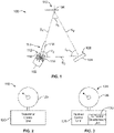
- Figure 4 illustrates a simplified schematic diagram of the bistatic radar system 100, according to an embodiment of the present disclosure.
- the positions 108 and 110 of the receiver 104 and the target 106, respectively may be known, while the position 112 of the transmitter 102 is unknown.
- the distances S 1 , S 2 , and S 3 , and the angles ⁇ 1 , ⁇ 2 , and ⁇ 3 may be determined, as described above.
- the distances S 1 , S 2 , and S 3 and the angles ⁇ 1 , ⁇ 2 , and ⁇ 3 reside within a plane 200 defined by the positions 108, 110, and 112.
- the transmitter position determination unit 130 may determine an elevation angle ⁇ 3 as detected by an antenna of the receiver 104.
- FIG. 5 illustrates a simplified schematic diagram of the bistatic radar system 100, according to an embodiment of the present disclosure.
- the positions 108 and 112 are known (such as through Equations 1-3), but the elevation L 2 of the target 106 may be unknown.
- the transmitter position determination unit 130 may determine the elevation angle ⁇ 2 as detected by an antenna of the receiver 104.
- the bistatic radar system 100 may continually monitor the positions of the receiver 104 and the target 106 and continually update the determination of the position of the transmitter 102.
- the transmitter position determination unit 130 may update position data regarding the receiver 104 and the target 106 and determine the position of the transmitter 102 once every X number of seconds.
- position data for the receiver 104 and the target 106 may be received by the transmitter position determination unit 130 every five seconds, and the transmitter position determination unit 130 may determine the position of the transmitter 102 accordingly (such as every five seconds). It is to be understood, however, that the updating period may be greater or less than five seconds. If the bistatic radar system 100 is configured to detect the positions of fast moving aircraft, for example, the updating period may be shorter than if the bistatic radar system 100 is configured to detect the positions of slower moving watercraft.
- any of the transmitter 102, the receiver 104, and the target 106 may be fixed or mobile.
- the transmitter 102, the receiver 104, or the target 106 may be positioned within an aircraft, land vehicle, watercraft, spacecraft, or the like.
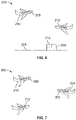
- FIG. 6 illustrates a simplified schematic diagram of a bistatic radar system 200, according to an embodiment of the present disclosure.
- the bistatic radar system 200 may include a receiver 202 positioned within a fixed structure 204, such as a building, positioned on land 206.
- a transmitter 208 may be secured within a first vehicle 210, such an aircraft.
- a second vehicle 212 such as a second aircraft, may be a target.
- the position of the transmitter 208 in relation to the receiver 202 may be determined as described above.
- the first and second vehicles 210, 212 may be various other vehicles, such as land vehicles or watercraft.
- the receiver 202 may be positioned within a mobile structure, such as a vehicle, whether land, air, or sea based.
- FIG. 7 illustrates a simplified schematic diagram of a bistatic radar system 300, according to an embodiment of the present disclosure.
- the bistatic radar system 300 may include a receiver 302 positioned within a first vehicle 304, such as a first aircraft.
- a transmitter 308 may be secured within a second vehicle 310, such a second aircraft.
- a third vehicle 312, such as a third aircraft, may be a target. The position of the transmitter 308 in relation to the receiver 302 may be determined as described above.
- the first and second vehicles 304, 310 may be various other vehicles, such as land vehicles or watercraft.
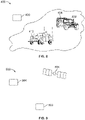
- FIG 8 illustrates a simplified schematic diagram of a bistatic radar system 400, according to an embodiment of the present disclosure.
- the bistatic radar system 400 may include a receiver 402 positioned within a first vehicle 404, such as a first land-based vehicle.
- a transmitter 408 may be located within a fixed structure, such as fixed to land, suspended within or above water, or the like. Alternatively, the transmitter 408 may be secured within a vehicle, such as an aircraft, land-based vehicle, watercraft, or the like.
- a second vehicle 412 such as a second land-based vehicle, may be a target. The position of the transmitter 408 in relation to the receiver 402 may be determined as described above.
- FIG. 9 illustrates a simplified schematic diagram of a bistatic radar system 500, according to an embodiment of the present disclosure.
- the bistatic radar system 500 may include a receiver 502 and a transmitter 504, which may be fixed or mobile, as described above.
- a geosynchronous satellite 506 that orbits Earth may serve as a target.
- the position of the transmitter 504 in relation to the receiver 502 may be determined as described above.
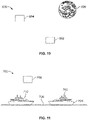
- FIG 10 illustrates a simplified schematic diagram of a bistatic radar system 600, according to an embodiment of the present disclosure.
- the bistatic radar system 600 may include a receiver 602 and a transmitter 604, which may be fixed or mobile, as described above.
- the receiver 602 and the transmitter 604 may be located within the atmosphere of the Earth, or within outer space, for example.
- the moon 606 or another celestial body may serve as a target.
- the position of the transmitter 604 in relation to the receiver 602 may be determined as described above.
- FIG 11 illustrates a simplified schematic diagram of a bistatic radar system 700, according to an embodiment of the present disclosure.
- the bistatic radar system 700 may include a receiver 702 onboard a ship 704 on a body of water 706.
- a transmitter 708 may be traveling through air, sea or land.
- a second ship 710 on the water 706 may serve as a target.
- the position of the transmitter 708 in relation to the receiver 702 may be determined as described above.
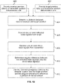
- Figure 12 illustrates a flow chart of a method of determining a position of a transmitter of a bistatic radar system, according to an embodiment of the present disclosure.
- receiver position data indicative of a position of a receiver is provided to a transmitter position determination unit, which may be housed within the receiver, or separate and distinct from the receiver.
- target position data indicative of a position of an auxiliary target is provided to the transmitter position determination unit.
- the transmitter position determination unit determines a distance between the receiver position and the target position based on the received receiver position data and the target position data. For example, by knowing the positions of the receiver and the target, the transmitter position determination unit may determine the distance therebetween, such as through subtraction.
- the receiver receives one or more reflected radar signals (such as portions of a main beam or sidelobe(s)) from the target.
- the transmitter position determination unit may analyze the reflected radar signal(s).
- the receiver receives one or more direct or incident radar signals (such as portions of sidelobe(s) or a main beam) from the transmitter.
- the transmitter position determination unit determines the angular difference between the reflected radar signal(s) and the direct radar signal(s). For example, the transmitter position determination unit may detect and analyze the angles of reception of the signals by an antenna of the receiver and determine the difference therebetween. At 812, the transmitter position determination unit uses the determined distance between the receiver position and the target position and the angular difference to determine the position of the transmitter relative to the receiver and the target.
- a transmitter position determination unit may determine the position of the transmitter relative to a receiver and a target based on known positions of the receiver and the target. Accordingly, while a position of the transmitter may be initially unknown, the transmitter position determination unit may determine the position of the transmitter by analyzing the positional data of the receiver and the target. The systems and methods may determine the position of the transmitter without communicating with the transmitter.
- Embodiments of the present disclosure provide bistatic radar systems and methods that eliminate the need for a costly communication system between a transmitter and a receiver.
- the term "computer,” “control unit,” or “module” may include any processor-based or microprocessor-based system including systems using microcontrollers, reduced instruction set computers (RISC), application specific integrated circuits (ASICs), logic circuits, and any other circuit or processor capable of executing the functions described herein.
- RISC reduced instruction set computers
- ASICs application specific integrated circuits
- the above examples are exemplary only, and are thus not intended to limit in any way the definition and/or meaning of the term "computer,” “control unit,” or “module.”
- the computer, control unit, or processor executes a set of instructions that are stored in one or more storage elements, in order to process data.
- the storage elements may also store data or other information as desired or needed.
- the storage element may be in the form of an information source or a physical memory element within a processing machine.
- the set of instructions may include various commands that instruct the computer, control unit, or processor as a processing machine to perform specific operations such as the methods and processes of the various embodiments of the subject matter described herein.
- the set of instructions may be in the form of a software program.
- the software may be in various forms such as system software or application software. Further, the software may be in the form of a collection of separate programs or modules, a program module within a larger program or a portion of a program module.
- the software also may include modular programming in the form of object-oriented programming.
- the processing of input data by the processing machine may be in response to user commands, or in response to results of previous processing, or in response to a request made by another processing machine.
- control units or modules represent one or more circuits, one or more circuit modules, or the like that may be implemented as hardware with associated instructions (e.g., software stored on a tangible and non-transitory computer readable storage medium, such as a computer hard drive, ROM, RAM, or the like) that perform the operations described herein.
- the hardware may include state machine circuitry hardwired to perform the functions described herein.
- the hardware may include electronic circuits that include and/or are connected to one or more logic-based devices, such as microprocessors, processors, controllers, or the like.
- the modules may represent processing circuitry such as one or more field programmable gate array (FPGA), application specific integrated circuit (ASIC), microprocessor(s), a quantum computing device, and/or the like.
- the circuit modules in various embodiments may be configured to execute one or more algorithms to perform functions described herein.
- the one or more algorithms may include aspects of embodiments disclosed herein, whether or not expressly identified in a flowchart or a method.
- the terms "software” and “firmware” are interchangeable, and include any computer program stored in memory for execution by a computer, including RAM memory, ROM memory, EPROM memory, EEPROM memory, and non-volatile RAM (NVRAM) memory.
- RAM memory random access memory
- ROM memory read-only memory
- EPROM memory erasable programmable read-only memory
- EEPROM memory electrically erasable programmable read-only memory
- NVRAM non-volatile RAM
Description
- Embodiments of the present disclosure generally relate to radar systems and methods.
- Radio detection and ranging (radar) systems generally use radio waves to determine a range, altitude, direction and/or speed of objects. Radar systems may be used to detect aircraft, ships, vehicles, guided missiles, weather, terrain, and the like. In general, a radar transmitter or illuminator includes an antenna that transmits pulses of radio waves or microwaves that encounter and reflect off an object. A portion of the energy of the reflected wave is received by an antenna of a radar receiver.
- In a monostatic radar system, the transmitter and receiver are located at the same position (that is, collocated). In contrast, a bistatic radar system includes a transmitter and a receiver at separate and distinct positions. For example, the transmitter and receiver of a bistatic radar system may be separated by hundreds of kilometers (miles).
- In order for a bistatic radar system to operate, the locations of both the transmitter and the receiver are known, whether or not either is moving. For example, in airborne applications, if both the transmitter and the receiver are moving (such as when onboard aircraft), the positions of both the transmitter and the receiver are frequently updated. Once the positions of the transmitter and the receiver are known, the positions of unknown targets with the range of the radar system may be determined.
- As can be appreciated, in order for a known bistatic radar system to properly function, the transmitter and the receiver communicate with one another or a remote control center in order to provide position information. As such, the transmitter and the receiver cooperate with one another in such a known bistatic radar system. However, providing a communication system between the transmitter and the receiver increases the cost and complexity of a radar system. Further, if the communication system malfunctions or is inoperative, the entire radar system is also inoperative.
- Additionally, if the transmitter and the receiver are controlled by separate and distinct entities, the system may not be able to operate. For example, a radar transmitter may be onboard an aircraft controlled or controlled by a first entity, such as a government, while a radar receiver may be onboard an aircraft controlled or owned by a separate and distinct entity that may or may not be cooperative or friendly with the first entity. In such a scenario, the transmitter may not communicate with the receiver, thereby preventing the receiver from utilizing a bistatic radar system that includes the transmitter.
- Document
US 5 327 145 A discloses a method of passive ranging and geolocation of multiple emitters by a single detection platform. Two independent emission sequences support formulation of two independent algebraic equations involving a triangular arrangement of platform and emitters. One sequence constitutes an interrogation signal by one emitter and a transponded or reflected signal from another. A second emission sequence constitutes the reversed order of emitters from those of the first emission sequence. The disclosed method utilizes the steps of measuring the time difference of arrival at the platform of signals having travelled the direct path and the transponded or reflected paths, and measuring the angles of arrival of received signals for each independent emission sequence. A series of steps computing ranges and angles based on prior measurements provide a set of desired ranges and angles identifying the relative positions of the emitters relative to the platform. The disclosed method may be employed in bistatic or transponded mode depending on the kind of signal emissions that are to be exploited. In the bistatic mode, the energy from an emitter is reflected from the other emitter. In the transponder mode the emitters communicate in an interrogation-transpond format with signals with known and small internal time delays. In the transponder mode, both signals are direct path signals. - Document
US 4 670 757 A discloses a method for passively locating in range and azimuth both active, such as radar, and passive objects. The disclosed method uses existing direction finding equipment located on a platform, such as an aircraft or ship. At the platform, the disclosed method includes measuring the scan period of the radar, the time of intercept of the main beam of the radar, the angle of arrival of the radar main beam, the time of arrival of a bistatic signal echo from a passive object which has been illuminated by the radar, and the angle of arrival of the echo; calculating the difference between the angle of arrival of the echo and the angle of arrival of the radar main beam to obtain an angle θ; determining an angle ϕ subtended by a line drawn from the platform to the passive object; determining the difference T between the time when the radar main beam passes the platform and the time of arrival of the echo; calculating the difference t between the time the bistatic signal travels the distance from the radar to the passive object to the platform and the time radar energy travels from the radar to the platform; and using θ, ϕ, and t to determine each range from the platform to the radar and from the platform to the passive object. - Document
US 3 939 476 A discloses a system for passively measuring the range between a given point and a second point from which detectable radiations having distinguishable characteristics are emanating, comprising means for receiving at said given point direct radiations from said second point and indirect radiations from said second point which have been reflected from a reflecting surface, means for measuring the angle of elevation of said second point from said given point, means for measuring the altitude of said given point relative to said reflecting surface, a gate circuit for rejecting all direct signals which are not followed by a reflecting signal within a predetermined time span, and computing means for determining the range from said given point to said second point as a function of said direct and reflected signal, said angle of elevation, and said altitude of said given point. - Document
US 5 280 294 A discloses a radar system for passive determination of range to a non-cooperative scanning radar, to a non-emitting object illuminated by the scanning emitter and between scanning emitter and illuminated object entirely from the passive location. The radar equipment at the passive location includes a passive array with beam forming and switching matrix to provide output signals separately on the basis of angular discrimination, for each of the object and emitter. Resolver circuits respond to the angle between emitter and object vector, the incremental time between direct emitter reception and reflected echo from the object as well as to emitter scan rate and instantaneous pointing angle. Algorithms for the emitter range, object range and range between emitter and object are given. - Document
US 4 746 924 A discloses determining the positions of a non-cooperative emitter (illuminator) and reflector (target) relative to a receiver of electromagnetic energy, which neither directly nor indirectly controls the illuminator, utilizing emissions received directly from the illuminator as well as reflected emissions from the target. A range RI between the receiver and the non-cooperative illuminator is determined by measuring the time difference between receiving the reflected signals at a pair of interferometer antennas located at the wing tips of a receiver aircraft. Calculation of the location of the target is accomplished by utilizing range RI, as well as a time differential Δ t between the receipt of the reflected signals at the interferometer antennas and the receipt of a corresponding direct signals at a radar antenna located at the aircraft. In the event there is clutter in the reflected signal which hinders the determination of the time differential Δ t, clutter processing is performed utilizing the direct signals as a coherent reference and by cross-correlating the direct and reflected signals. The determination of the bearing of the target and the illuminator relative to the receiver is accomplished by an amplitude comparison of the signals received at multiple ports of a multiple beamed phased array radar antenna. The bearing information together with the range and time differential is processed to provide the necessary commands for generating a visual display of the positions of target and illuminator relative to the receiver. - And finally, document
US 4 980 690 A discloses a semi-active radar receiver for receiving a sequence of radar pulses and providing radar timing signals in response thereto. In a most general sense, the semi-active receiver of that document includes a receiver for receiving a direct transmission of a series of pulses from a radar transmitter and for providing a series of first signal pulses in response thereto. A range gate generator is included for processing the series of first pulses to provide said radar timing signals. In a more specific embodiment, the receiver includes a filter for processing said received pulses and deriving estimates of the timing of the receipt thereof. The estimates are then used by the range gate generator to provide said radar timing signals. - The present disclosure provides a bistatic radar system as defined in claim 1. Further embodiments of this bistatic radar system for the subject matter of dependent claims 2-10.
- The present disclosure further provides a bistatic radar method as defined in claim 11. Embodiments of this bistatic radar method are defined in dependent claims 12-15.
-
-
Figure 1 illustrates a simplified schematic diagram of a bistatic radar system, according to an embodiment of the present disclosure. -
Figure 2 illustrates a simplified schematic diagram of a bistatic radar transmitter, according to an embodiment of the present disclosure. -
Figure 3 illustrates a simplified schematic diagram of a bistatic radar receiver, according to an embodiment of the present disclosure. -
Figure 4 illustrates a simplified schematic diagram of a bistatic radar system, according to an embodiment of the present disclosure. -
Figure 5 illustrates a simplified schematic diagram of a bistatic radar system, according to an embodiment of the present disclosure. -
Figure 6 illustrates a simplified schematic diagram of a bistatic radar system, according to an embodiment of the present disclosure. -
Figure 7 illustrates a simplified schematic diagram of a bistatic radar system, according to an embodiment of the present disclosure. -
Figure 8 illustrates a simplified schematic diagram of a bistatic radar system, according to an embodiment of the present disclosure. -
Figure 9 illustrates a simplified schematic diagram of a bistatic radar system, according to an embodiment of the present disclosure. -
Figure 10 illustrates a simplified schematic diagram of a bistatic radar system, according to an embodiment of the present disclosure. -
Figure 11 illustrates a simplified schematic diagram of a bistatic radar system, according to an embodiment of the present disclosure. -
Figure 12 illustrates a flow chart of a method of determining a position of a transmitter of a bistatic radar system, according to an embodiment of the present disclosure. - The foregoing summary, as well as the following detailed description of certain embodiments will be better understood when read in conjunction with the appended drawings.
- Embodiments of the present disclosure provide systems and methods of determining a position of a transmitter of a bistatic radar system. The transmitter may refrain from communicating with a receiver. For example, the transmitter and the receiver may not communicate position information with one another. Instead, the systems and methods of the present disclosure are configured to determine the location or position of the transmitter by detecting radar signals transmitted by the transmitter.
-
Figure 1 illustrates a simplified schematic of abistatic radar system 100, according to an embodiment of the present disclosure. Thebistatic radar system 100 includes a transmitter orilluminator 102 that is separated from areceiver 104. Thetransmitter 102 and thereceiver 104 may be separated by any distance, which may or may not be a fixed distance. For example, one or both of thetransmitter 102 and thereceiver 104 may be onboard air, land, sea, or space vehicles that move. Optionally, one or both of thetransmitter 102 and thereceiver 104 may be at fixed locations, such as within buildings at fixed locations on land, or under water, and the like. - The
bistatic radar system 100 also includes atarget 106. Thetarget 106 may be a moving or fixed object, vehicle, landmark, monument, terrain feature, or the like. As shown inFigure 1 , thetarget 106 may be an aircraft. - The positions of the
receiver 104 and thetarget 106 are known. For example, thereceiver 104 is at a firstknown position 108, which may be on or in land, sea, or air, while thetarget 106 is at a secondknown position 110, which may differ from the firstknown position 108. In contrast, thetransmitter 102 is at an initiallyunknown position 112, which may on or in land, sea, or air. - The positions of the
receiver 104 and thetarget 106 may be known through various systems and methods. For example, each of thereceiver 104 and thetarget 106 may include global position system (GPS) units or devices that determine the respective positions. Thereceiver 104 and thetarget 106 may be in communication with one another, such as through dedicated wireless links, voice communication links (for example, an individual at each position may call in the position data), or the like, so that thetarget 106 may continually communicate its position to thereceiver 104. - As shown, the
transmitter 102 is separated from thetarget 106 by a distance S1, which is an initially unknown distance. Thetarget 106 is separated from thereceiver 104 by a distance S2, which is a known distance. Thereceiver 104 is separated from thetransmitter 102 by a distance S3, which is an initially unknown distance. The angle between S2 and S3 is θ1. The angle between the S1 and S3 is θ2. The angle between S1 and S2 is θ3. - In operation, the
transmitter 102 transmits one or more radar signals 113, which may include amain beam 114 andsidelobes 116. At least portions of themain beam 114 and/or thesidelobes 116 are reflected off thetarget 106 and received by thereceiver 104. -
Figure 2 illustrates a simplified schematic diagram of abistatic radar transmitter 118, according to an embodiment of the present disclosure. Thetransmitter 118 is an example of thetransmitter 102, shown inFigure 1 . Thetransmitter 118 may include atransmitter control unit 120 operatively connected to asignal generator 122, such as an antenna, dish, or the like. Thetransmitter control unit 120 may be or include one or more processors, circuits, modules, or the like that are configured to control operation of thetransmitter 118. For example, thetransmitter control unit 120 may control a radar signal transmitted from thesignal generator 122. - The
transmitter 118 may transmit pulsed radar signals, which may include themain beam 114 and thesidelobes 116. For a high pulse repetition frequency (PRF) radar, multiple coherent processing intervals (CPIs) that have different PRFs may be used to disambiguate range using the Chinese Remainder Theorem or other such technique. - In at least one embodiment, the transmitter 102 (shown in
Figure 1 ) may include thesignal generator 122, which may be a slowly rotating (for example, a period of 10 seconds) antenna or dish. Thesignal generator 122 may rotate at a regular and predictable speed. Accordingly, the angle θ1 may be determined by determining a time difference between the reception of the reflected radar signals from thetarget 106, and the direct reception of the incident radar signals from thetransmitter 102. -
Figure 3 illustrates a simplified schematic diagram of abistatic radar receiver 124, according to an embodiment of the present disclosure. Thereceiver 124 is an example of thereceiver 104, shown inFigure 1 . Thereceiver 104 may include areceiver control unit 126 operatively connected to a signal-receivingstructure 128, such an antenna or dish. The signal-receivingstructure 128 may be pointed at the knownposition 110 of thetarget 106. Thereceiver control unit 126 may be or include one or more processors, circuits, modules, or the like that are configured to control operation of thereceiver 124. For example, thereceiver control unit 126 may analyze radar signals received through the signal-receivingstructure 128. The signal-receivingstructure 128 may be fixed with respect to a platform or main housing of thereceiver 124. Receive antenna beams of the signal-receivingstructure 128 may be electronically steered. - The
receiver 124 may also include a transmitterposition determination unit 130, which may include one or more processors, circuits, modules, or the like. The transmitterposition determination unit 130 may be part of thereceiver control unit 126. Optionally, the transmitterposition determination unit 130 may be separate and distinct from thereceiver control unit 126. For example, the transmitterposition determination unit 130 may be housed within thereceiver 124 and in communication with thereceiver control unit 126. Alternatively, the transmitterposition determination unit 130 may be separate and distinct from thereceiver 124. For example, the transmitterposition determination unit 130 may be positioned at a separate and distinct location from thereceiver 124, and in communication with thereceiver control unit 126. The transmitterposition determination unit 130 is configured to receive one or more radar signals and determine the position of thetransmitter 102, as explained below. - The receiver 104 (shown in
Figure 1 ) may include the signal-receivingstructure 128, which may be or otherwise include a directional antenna or dish pointed toward thetarget 106. For example, the directional antenna of thereceiver 104 may include multiple beams, or may be scanned with a single beam. - In at least one embodiment, the transmitter
position determination unit 130 may determine a bistatic range difference by measuring a time difference between a reception of direct pulses fromradar sidelobes 116 and reflected pulses from thetarget 106. The transmitterposition determination unit 130 may convert the time difference to a range difference by multiplying the time difference by the speed of light. - Referring to
Figures 1-3 , the transmitterposition determination unit 130 may determine the angle θ1 based on radar signals received by thereceiver 104. For example, the signal-receivingstructure 128 may be a directional antenna (such as a digitally-steered beamformer) that receives at least a portion of themain beam 114 or asidelobe 116 reflected off thetarget 106, and at least a portion of themain beam 114 or asidelobe 116 transmitted from thetransmitter 102. - The transmitter
position determination unit 130 may analyze the received signals and determine the difference between the reception angles of the received signals in relation to the signal-receivingstructure 128. The difference between the reception angles of the two separate signals (for example, at least a portion of themain beam 114 reflected off thetarget 106 and at least a portion of a sidelobe 116) provides the angle θ1. - The
position determination unit 130 may determine the relative position of thetransmitter 102 with respect to thereceiver 104 by analyzing, at least in part, reflected radar signals (such as reflected portions of themain beam 114 and/or the sidelobes 116) from thetarget 106. Theposition determination unit 130 may also analyze direct or incident radar signals (such as direct or incident portions of themain beam 114 and/or the sidelobes 116) transmitted from thetransmitter 102. For example, thereceiver 104 receives reflected radar signals from thetarget 106 along the distance S2, which is a known distance. Thereceiver 104 also receives direct or incident radar signals from thetransmitter 102 along the distance S3. Theposition determination unit 130 analyzes the received reflected and direct radar signals to determine the angle θ1, such as through an analysis of the angle of reception by the antenna or dish of thereceiver 104, as described above. Theposition determination unit 130 then determines the distance S3, and therefore theposition 112, based on the known distance S2 and the angle θ1, as described below. - The transmitter
position determination unit 130 determines the distance S2, by comparing the known position of thereceiver 104 with the known position of thetarget 106. For example, the transmitterposition determination unit 130 may subtract the knownposition 110 of thetarget 106 from the knownposition 108 of thereceiver 104 to determine the distance S2. The transmitterposition determination unit 130 then proceeds to determine S3, and thus theposition 113 of thetransmitter 102, as described below. - The
receiver 104 may receive a reflected radar signal from thetarget 106 at a first time T1. Thereceiver 104 may also receive a direct or incident signal from thetransmitter 102 at a second time T2 that differs from the first time. The first time T1 may precede the second time T2, or vice versa. The reflected radar signal may include at least a portion of themain beam 114 reflected off thetarget 106. Alternatively, the reflected radar signal may include at least a portion of asidelobe 116 reflected off thetarget 106. The direct or incident signal may include at least a portion of asidelobe 116 directly transmitted from thetransmitter 102 along the linear distance S3. Alternatively, the direct or incident signal may include at least a portion of themain beam 114 directly transmitted from thetransmitter 102 along the linear distance S3. The distances S1, S2, and S3 relate to the times T1 and T2 as follows:
- A value K may be determined as follows:

- K may be determined based on the known or measured values for C, T1, T2, and S2, such that

- As noted, the distance S2 is known because it is the distance between the known
positions - The distance S3 may then be determined as follows:

- As described above, the transmitter
position determination unit 130 is able to determine the angle θ1. Further, the transmitterposition determination unit 130 knows or otherwise determines the distance S2 based on the knownpositions receiver 104 and thetarget 106, respectively. By knowing the distance S2, and determining the angle θ1, the transmitterposition determination unit 130 is able to determine the distance S3, and thus theposition 112. - Once the transmitter
position determination unit 130 determines theposition 112 of thetransmitter 102, thereceiver control unit 126 may then determine the position of all unknown target positions within the range of thebistatic radar system 100. Accordingly, embodiments of the present disclosure provide a system and method of determining the position of thetransmitter 102, even if thetransmitter 102 is not in communication with thereceiver 104. By knowing thepositions receiver 104 and thetarget 106, respectively, the transmitterposition determination unit 130 determines the distance S2 therebetween. Further, thereceiver 104 determines the angle θ1 by receiving at least a portion of the main beam 114 (or a sidelobe 116) reflected off thetarget 106, and at least another portion of themain beam 114 and/or asidelobe 116 directly from thetransmitter 102. The transmitterposition determination unit 130 then determines the distance S3 and thus theposition 112 of thetransmitter 102 based on the determination of S2 and the angle θ1. - The transmitter
position determination unit 130 is configured to determine theposition 112 of thetransmitter 102 even if thereceiver 104 and/or thetarget 106 do not communicate with thetransmitter 102. By not communicating with thetransmitter 102, thebistatic radar system 100 may operate during times, such as during military missions or operations, when a communication link between thetransmitter 102 and thereceiver 104 is impractical and/or threatening to an objective. For example, an enemy combatant may intercept communications over a communication link. Further, thebistatic radar system 100 may be used even if thetransmitter 102 is uncooperative (for example, refuses to communicate its position) with thereceiver 104. - As noted, the
transmitter 102 may include thesignal generator 122, which may be or otherwise include a spinning radar member, such as an antenna or dish. For a spinning radar member with constant rotational speed, by measuring the radar rotational speed and determining the difference between the time when themain beam 114 points at thereceiver 104 and the time when the reflected signal from thetarget 106 is received by thereceiver 104, the angle θ2 may be determined. As such, the additional determination of the angle θ2 may be used to check the accuracy of the determination of the position of thetransmitter 102. For example, the transmitterposition determination unit 130 may be supplied with data regarding the rotational speed of the spinning radar member of thetransmitter 102. As an example, the spinning radar member may make a full 360 degree rotation every 10 seconds. The transmitterposition determination unit 130 may also detect when themain beam 104 points at thereceiver 104 and when the radar signal is received as a reflected signal from thetarget 106. As such, the transmitterposition determination unit 130 may then determine the angle θ2. The transmitterposition determination unit 130 may then determine whether the distances S1, S2, and S3 are in agreement based on the angle θ1, which thetransmitter determination unit 130 knows, the angle θ2, which thetransmitter determination unit 130 has determined, and the angle θ3, which the transmitterposition determination unit 130 may determine by subtracting θ1 + θ2 from 180 degrees. If the distances S1, S2, and S3 are in agreement with a triangle having such angles, then the accuracy of the distance S3 may be confirmed. If, however, the distances S1, S2, and S3 are not in agreement with a triangle having such angles, then the transmitterposition determination unit 130 may transmit an alert message that the distance S3 (and therefore the determined location 112) may be inaccurate. - Equations 1-4 described above provide 2 dimensional equations that are configured to determine the geometry of a triangle. However, Equations 1-4 may not determine the orientation of the triangle in 3-dimensional space alone. The locations of two of the three vertices of the triangle may be hypothetically determined. The location of the third unknown vertex may not be hypothetically determined. To determine the location of the third vertex, the altitude of the vertex relative to the
receiver 104 may be known. The antenna of thereceiver 104 may be used to determine the elevation angle. -
Figure 4 illustrates a simplified schematic diagram of thebistatic radar system 100, according to an embodiment of the present disclosure. InFigure 4 , thepositions receiver 104 and thetarget 106, respectively, may be known, while theposition 112 of thetransmitter 102 is unknown. The distances S1, S2, and S3, and the angles θ1, θ2, and θ3 may be determined, as described above. Notably, the distances S1, S2, and S3 and the angles θ1, θ2, and θ3 reside within aplane 200 defined by thepositions - To determine an elevation of the
transmitter 102 relative to thereceiver 104, the transmitterposition determination unit 130 may determine an elevation angle Φ3 as detected by an antenna of thereceiver 104. The altitude of thetransmitter 102 relative to thereceiver 104 may then be determined as follows:
receiver 104 resides to theposition 112, and S3 is determined through Equation 3. Once theposition 112 and altitude L3 of thetransmitter 102 have been determined, such as by the transmitter position determination unit 130 (shown inFigure 3 ), positions of unknown targets may be detected in 3-dimensional space. -
Figure 5 illustrates a simplified schematic diagram of thebistatic radar system 100, according to an embodiment of the present disclosure. As shown inFigure 5 , thepositions target 106 may be unknown. To determine the elevation L2 of thetarget 106 relative to thereceiver 104, the transmitterposition determination unit 130 may determine the elevation angle Φ2 as detected by an antenna of thereceiver 104. The elevation or altitude of thetarget 106 relative to thereceiver 104 may then be determined as follows:
receiver 104 resides to theposition 110, and S2 is known, as described above. - Referring to
Figures 1-5 , thebistatic radar system 100 may continually monitor the positions of thereceiver 104 and thetarget 106 and continually update the determination of the position of thetransmitter 102. For example, the transmitterposition determination unit 130 may update position data regarding thereceiver 104 and thetarget 106 and determine the position of thetransmitter 102 once every X number of seconds. For example, position data for thereceiver 104 and thetarget 106 may be received by the transmitterposition determination unit 130 every five seconds, and the transmitterposition determination unit 130 may determine the position of thetransmitter 102 accordingly (such as every five seconds). It is to be understood, however, that the updating period may be greater or less than five seconds. If thebistatic radar system 100 is configured to detect the positions of fast moving aircraft, for example, the updating period may be shorter than if thebistatic radar system 100 is configured to detect the positions of slower moving watercraft. - Any of the
transmitter 102, thereceiver 104, and thetarget 106 may be fixed or mobile. For example, thetransmitter 102, thereceiver 104, or thetarget 106 may be positioned within an aircraft, land vehicle, watercraft, spacecraft, or the like. -
Figure 6 illustrates a simplified schematic diagram of abistatic radar system 200, according to an embodiment of the present disclosure. Thebistatic radar system 200 may include areceiver 202 positioned within a fixedstructure 204, such as a building, positioned onland 206. Atransmitter 208 may be secured within afirst vehicle 210, such an aircraft. Asecond vehicle 212, such as a second aircraft, may be a target. The position of thetransmitter 208 in relation to thereceiver 202 may be determined as described above. Alternatively, the first andsecond vehicles receiver 202 may be positioned within a mobile structure, such as a vehicle, whether land, air, or sea based. -
Figure 7 illustrates a simplified schematic diagram of abistatic radar system 300, according to an embodiment of the present disclosure. Thebistatic radar system 300 may include areceiver 302 positioned within afirst vehicle 304, such as a first aircraft. Atransmitter 308 may be secured within asecond vehicle 310, such a second aircraft. Athird vehicle 312, such as a third aircraft, may be a target. The position of thetransmitter 308 in relation to thereceiver 302 may be determined as described above. Alternatively, the first andsecond vehicles -
Figure 8 illustrates a simplified schematic diagram of abistatic radar system 400, according to an embodiment of the present disclosure. Thebistatic radar system 400 may include areceiver 402 positioned within afirst vehicle 404, such as a first land-based vehicle. Atransmitter 408 may be located within a fixed structure, such as fixed to land, suspended within or above water, or the like. Alternatively, thetransmitter 408 may be secured within a vehicle, such as an aircraft, land-based vehicle, watercraft, or the like. Asecond vehicle 412, such as a second land-based vehicle, may be a target. The position of thetransmitter 408 in relation to thereceiver 402 may be determined as described above. -
Figure 9 illustrates a simplified schematic diagram of abistatic radar system 500, according to an embodiment of the present disclosure. Thebistatic radar system 500 may include areceiver 502 and atransmitter 504, which may be fixed or mobile, as described above. Ageosynchronous satellite 506 that orbits Earth may serve as a target. The position of thetransmitter 504 in relation to thereceiver 502 may be determined as described above. -
Figure 10 illustrates a simplified schematic diagram of abistatic radar system 600, according to an embodiment of the present disclosure. Thebistatic radar system 600 may include areceiver 602 and atransmitter 604, which may be fixed or mobile, as described above. Thereceiver 602 and thetransmitter 604 may be located within the atmosphere of the Earth, or within outer space, for example. Themoon 606 or another celestial body may serve as a target. The position of thetransmitter 604 in relation to thereceiver 602 may be determined as described above. -
Figure 11 illustrates a simplified schematic diagram of abistatic radar system 700, according to an embodiment of the present disclosure. Thebistatic radar system 700 may include areceiver 702 onboard aship 704 on a body ofwater 706. Atransmitter 708 may be traveling through air, sea or land. Asecond ship 710 on thewater 706 may serve as a target. The position of thetransmitter 708 in relation to thereceiver 702 may be determined as described above. -
Figure 12 illustrates a flow chart of a method of determining a position of a transmitter of a bistatic radar system, according to an embodiment of the present disclosure. At 800, receiver position data indicative of a position of a receiver is provided to a transmitter position determination unit, which may be housed within the receiver, or separate and distinct from the receiver. At 802, target position data indicative of a position of an auxiliary target is provided to the transmitter position determination unit. - At 804, the transmitter position determination unit determines a distance between the receiver position and the target position based on the received receiver position data and the target position data. For example, by knowing the positions of the receiver and the target, the transmitter position determination unit may determine the distance therebetween, such as through subtraction.
- Next, at 806, the receiver receives one or more reflected radar signals (such as portions of a main beam or sidelobe(s)) from the target. The transmitter position determination unit may analyze the reflected radar signal(s). At 808, the receiver receives one or more direct or incident radar signals (such as portions of sidelobe(s) or a main beam) from the transmitter.
- At 810, the transmitter position determination unit determines the angular difference between the reflected radar signal(s) and the direct radar signal(s). For example, the transmitter position determination unit may detect and analyze the angles of reception of the signals by an antenna of the receiver and determine the difference therebetween. At 812, the transmitter position determination unit uses the determined distance between the receiver position and the target position and the angular difference to determine the position of the transmitter relative to the receiver and the target.
- As described above, embodiments of the present disclosure provide systems and methods of determining a position of a transmitter of a bistatic radar system. A transmitter position determination unit may determine the position of the transmitter relative to a receiver and a target based on known positions of the receiver and the target. Accordingly, while a position of the transmitter may be initially unknown, the transmitter position determination unit may determine the position of the transmitter by analyzing the positional data of the receiver and the target. The systems and methods may determine the position of the transmitter without communicating with the transmitter.
- Embodiments of the present disclosure provide bistatic radar systems and methods that eliminate the need for a costly communication system between a transmitter and a receiver.
- As used herein, the term "computer," "control unit," or "module" may include any processor-based or microprocessor-based system including systems using microcontrollers, reduced instruction set computers (RISC), application specific integrated circuits (ASICs), logic circuits, and any other circuit or processor capable of executing the functions described herein. The above examples are exemplary only, and are thus not intended to limit in any way the definition and/or meaning of the term "computer," "control unit," or "module."
- The computer, control unit, or processor executes a set of instructions that are stored in one or more storage elements, in order to process data. The storage elements may also store data or other information as desired or needed. The storage element may be in the form of an information source or a physical memory element within a processing machine.
- The set of instructions may include various commands that instruct the computer, control unit, or processor as a processing machine to perform specific operations such as the methods and processes of the various embodiments of the subject matter described herein. The set of instructions may be in the form of a software program. The software may be in various forms such as system software or application software. Further, the software may be in the form of a collection of separate programs or modules, a program module within a larger program or a portion of a program module. The software also may include modular programming in the form of object-oriented programming. The processing of input data by the processing machine may be in response to user commands, or in response to results of previous processing, or in response to a request made by another processing machine.
- The diagrams of embodiments herein may illustrate one or more control units or modules. It is to be understood that the control units or modules represent one or more circuits, one or more circuit modules, or the like that may be implemented as hardware with associated instructions (e.g., software stored on a tangible and non-transitory computer readable storage medium, such as a computer hard drive, ROM, RAM, or the like) that perform the operations described herein. The hardware may include state machine circuitry hardwired to perform the functions described herein. Optionally, the hardware may include electronic circuits that include and/or are connected to one or more logic-based devices, such as microprocessors, processors, controllers, or the like. Optionally, the modules may represent processing circuitry such as one or more field programmable gate array (FPGA), application specific integrated circuit (ASIC), microprocessor(s), a quantum computing device, and/or the like. The circuit modules in various embodiments may be configured to execute one or more algorithms to perform functions described herein. The one or more algorithms may include aspects of embodiments disclosed herein, whether or not expressly identified in a flowchart or a method.
- As used herein, the terms "software" and "firmware" are interchangeable, and include any computer program stored in memory for execution by a computer, including RAM memory, ROM memory, EPROM memory, EEPROM memory, and non-volatile RAM (NVRAM) memory. The above memory types are exemplary only, and are thus not limiting as to the types of memory usable for storage of a computer program.
Claims (15)
- A bistatic radar system comprising:a transmitter (102);a target (106) at a first position (110);a receiver including an antenna (104) at a second known position (108), wherein the receiver is configured to receive one or more reflected radar signals (113) transmitted from the transmitter and reflected off the target, and wherein the receiver is configured to receive one or more direct radar signals (113) transmitted from the transmitter; anda transmitter position determination unit (130) configured to determine a position (112) of the transmitter (102) based on a determination of a distance between the first position (110) and the second known position (108) and a determination of a first angular difference between the one or more reflected radar signals and the one or more direct radar signals that are received by the receiver;said bistatic radar system being characterized in that:the first position of the target (106) is a first known position (110):the transmitter position determination unit (130) is configured to determine one or both of a first elevation (L3) of the transmitter (102) relative to the receiver (104) or a second elevation (L2) of the target (106) relative to the receiver (104);the antenna is configured to determine one or both of a first elevation angle (Φ3) of the transmitter (102) relative to the receiver (104) or a second elevation angle (Φ2) of the target (106) relative to the receiver (104); andthe transmitter position determination unit (130) is configured to determine the first elevation (L3) as L3 = S3sin Φ3 and to determine the second elevation (L2) as L2 = S2sin Φ2, wherein S3 is a linear distance separating the receiver from the transmitter and S2 is a linear distance separating the target from the receiver.
- The bistatic radar system of claim 1, wherein the transmitter refrains from communicating the position of the transmitter.
- The bistatic radar system of any of claims 1-2, wherein the receiver includes the transmitter position determination unit.
- The bistatic radar system of any of claims 1-3, wherein the transmitter position determination unit is configured to determine a bistatic range difference by measuring a time difference between a first time (T1) when the one or more reflected radar signals or the one or more direct radar signals are received by the receiver and a second time (T2) when the other of the one or more reflected radar signals or the one or more direct radar signals are received by the receiver.
- The bistatic radar system of claim 4, wherein the transmitter position determination unit is configured to convert the time difference to the bistatic range difference by multiplying the time difference by the speed of light.
- The bistatic radar system of any of claims 4-5, wherein the transmitter is separated from the target by a first linear distance (S1), the target is separated from the receiver by a second linear distance (S2), and the receiver is separated from the transmitter by a third linear distance (S3), wherein the transmitter position determination unit is configured to relate the first, second, and third distances to the first and second times as S1 + S2 - S3 = C∗(T1-T2), wherein C is the speed of light.
- The bistatic radar system of claim 6, wherein the transmitter position determination unit is configured to determine K = S1 - S3, such that K = C ∗ (T1-T2) - S2.
- The bistatic radar system of claim 7, wherein the transmitter position determination unit is configured to determine the third distance as S3 = (S2 2 - K2)/(2S2cosθ1 + 2K).
- The bistatic radar system of any of the preceding claims, wherein the transmitter position determination unit is configured to determine a second angular difference between a main beam transmitted from the transmitter towards the target and a sidelobe transmitted from the transmitter toward the receiver, and wherein the transmitter position determination unit uses the second angular difference to determine an accuracy of the determined position of the transmitter.
- The bistatic radar system of any of the preceding claims, wherein each of the transmitter, the receiver, and the target are moving or fixed in position.
- A bistatic radar method comprising:providing receiver position data indicative of a second position (108) of a receiver (104) to a transmitter position determination unit (130);receiving, with the receiver, one or more reflected radar signals (113) transmitted from a transmitter (112) and reflected off a target (106);receiving, with the receiver, one or more direct radar signals (113) transmitted from the transmitter; anddetermining a third position (112) of the transmitter, with the transmitter position determination unit, based on a distance between a first position (110) of the target (106) and the second position (108) of the receiver (104) and a first angular difference between the one or more reflected radar signals and the one or more direct radar signals;said method being characterized in that:target position data indicative of the first position (110) of the target (106) is provided to the transmitter position determination unit (130);the method further comprises determining one or both of a first elevation (L3) of the transmitter (102) relative to the receiver (104) or a second elevation (L2) of the target (106) relative to the receiver (104);the method further comprises using an antenna of the receiver to determine one or both of a first elevation angle (Φ3) of the transmitter (102) relative to the receiver (104) or a second elevation angle (Φ2) of the target (106) relative to the receiver (104); andthe method further comprises determining, with the transmitter position determination unit (130), the first elevation (L3) as L3 = S3sin Φ3 and the second elevation (L2) as L2 = S2sin Φ2, wherein S3 is a linear distance separating the receiver from the transmitter and S2 is a linear distance separating the target from the receiver.
- The bistatic radar method of claim 11, further comprising refraining from communicating the third position data from the transmitter.
- The bistatic radar method of claim 11 or 12, further comprising:
determining a second angular difference between a main beam transmitted from the transmitter towards the target and a sidelobe transmitted from the transmitter toward the receiver, using the second angular difference to determine an accuracy of the determined position of the transmitter. - The bistatic radar method of any of claims 11-13, further comprising:
determining, with the transmitter position determination unit, a bistatic range difference by measuring a time difference between a first time (T1) when the one or more reflected radar signals or the one or more direct radar signals are received by the receiver and a second time (T2) when the other of the one or more reflected radar signals or the one or more direct radar signals are received by the receiver. - The bistatic radar method of claim 14, further comprising:
converting, with the transmitter position determination unit, the time difference to the bistatic range difference by multiplying the time difference by the speed of light.
Applications Claiming Priority (2)
| Application Number | Priority Date | Filing Date | Title |
|---|---|---|---|
| US14/461,579 US9709662B2 (en) | 2014-08-18 | 2014-08-18 | Systems and methods for determining a position of a transmitter of a bistatic radar system |
| EP15181425.8A EP2988148B1 (en) | 2014-08-18 | 2015-08-18 | Systems and methods for determining a position of a transmitter of a bistatic radar system |
Related Parent Applications (2)
| Application Number | Title | Priority Date | Filing Date |
|---|---|---|---|
| EP15181425.8A Division EP2988148B1 (en) | 2014-08-18 | 2015-08-18 | Systems and methods for determining a position of a transmitter of a bistatic radar system |
| EP15181425.8A Division-Into EP2988148B1 (en) | 2014-08-18 | 2015-08-18 | Systems and methods for determining a position of a transmitter of a bistatic radar system |
Publications (2)
| Publication Number | Publication Date |
|---|---|
| EP3540461A1 EP3540461A1 (en) | 2019-09-18 |
| EP3540461B1 true EP3540461B1 (en) | 2022-04-06 |
Family
ID=53871988
Family Applications (2)
| Application Number | Title | Priority Date | Filing Date |
|---|---|---|---|
| EP15181425.8A Active EP2988148B1 (en) | 2014-08-18 | 2015-08-18 | Systems and methods for determining a position of a transmitter of a bistatic radar system |
| EP19173090.2A Active EP3540461B1 (en) | 2014-08-18 | 2015-08-18 | Systems and methods for determining a position of a transmitter of a bistatic radar system |
Family Applications Before (1)
| Application Number | Title | Priority Date | Filing Date |
|---|---|---|---|
| EP15181425.8A Active EP2988148B1 (en) | 2014-08-18 | 2015-08-18 | Systems and methods for determining a position of a transmitter of a bistatic radar system |
Country Status (5)
| Country | Link |
|---|---|
| US (1) | US9709662B2 (en) |
| EP (2) | EP2988148B1 (en) |
| JP (1) | JP6655900B2 (en) |
| KR (1) | KR102403181B1 (en) |
| CN (1) | CN105372626B (en) |
Families Citing this family (14)
| Publication number | Priority date | Publication date | Assignee | Title |
|---|---|---|---|---|
| KR102258059B1 (en) * | 2014-08-14 | 2021-05-28 | 삼성전자주식회사 | Wireless distance measurement apparatus and method |
| US10281571B2 (en) * | 2014-08-21 | 2019-05-07 | Raytheon Company | Phased array antenna using stacked beams in elevation and azimuth |
| US10324167B2 (en) * | 2016-09-12 | 2019-06-18 | The Boeing Company | Systems and methods for adding functional grid elements to stochastic sparse tree grids for spatial filtering |
| US10324168B2 (en) | 2016-09-12 | 2019-06-18 | The Boeing Company | Systems and methods for spatial filtering using data with widely different error magnitudes |
| US10429491B2 (en) | 2016-09-12 | 2019-10-01 | The Boeing Company | Systems and methods for pulse descriptor word generation using blind source separation |
| US9954561B2 (en) | 2016-09-12 | 2018-04-24 | The Boeing Company | Systems and methods for parallelizing and pipelining a tunable blind source separation filter |
| KR102578824B1 (en) | 2016-11-30 | 2023-09-15 | 삼성전자주식회사 | Vehicle radar apparatus providing 3-dimensional information |
| CN106932759B (en) * | 2017-01-17 | 2020-08-14 | 电子科技大学 | Cooperative positioning method for active and passive radars |
| WO2018141613A1 (en) * | 2017-02-02 | 2018-08-09 | Fraunhofer-Gesellschaft zur Förderung der angewandten Forschung e.V. | Positioning of unmanned aerial vehicles using millimeter-wave beam infrastructure |
| US10473759B2 (en) * | 2017-03-28 | 2019-11-12 | GM Global Technology Operations LLC | Tool for automatic multiple radar calibration |
| KR102647167B1 (en) | 2017-05-12 | 2024-03-13 | 로카타 코퍼레이션 피티와이 리미티드 | Method and apparatus for characterizing the environment of a user platform |
| US10901065B2 (en) | 2017-10-11 | 2021-01-26 | The Boeing Company | Location determination of an emitter using frequency-of-arrival (FOA) measured from a single moving platform |
| US11002819B2 (en) * | 2018-04-24 | 2021-05-11 | The Boeing Company | Angular resolution of targets using separate radar receivers |
| US20200049808A1 (en) * | 2018-08-10 | 2020-02-13 | GM Global Technology Operations LLC | Target position estimation from cross transmission reflections of unsynchronized radars |
Family Cites Families (11)
| Publication number | Priority date | Publication date | Assignee | Title |
|---|---|---|---|---|
| US3939476A (en) | 1959-05-19 | 1976-02-17 | Leopard George W | Passive ranging tail warning device |
| US5280294A (en) * | 1983-11-25 | 1994-01-18 | Itt Corporation | Passive monopulse ranging to a non-cooperative emitter and non-emitting object |
| US4670757A (en) | 1985-04-26 | 1987-06-02 | Eaton Corporation | Bistatic object location method |
| US4746924A (en) | 1985-09-30 | 1988-05-24 | The Boeing Company | Apparatus and methods for locating a target utilizing signals generated from a non-cooperative source |
| US4980690A (en) | 1989-10-24 | 1990-12-25 | Hughes Aircraft Company | Bistatic radar seeker with range gating |
| US5327145A (en) * | 1990-05-22 | 1994-07-05 | Hughes Aircraft Company | Time delay passive ranging technique |
| JPH08201501A (en) * | 1995-01-24 | 1996-08-09 | Nec Corp | Electric wave source locating device |
| US6608593B2 (en) * | 2001-06-25 | 2003-08-19 | Harris Corporation | System and method for determining the location of a transmitter using passive reflectors or refractors as proxy receivers |
| JP3759458B2 (en) * | 2002-02-05 | 2006-03-22 | 三菱電機株式会社 | Radar system and target detection method |
| FR2940462B1 (en) * | 2008-12-23 | 2012-01-20 | Thales Sa | METHOD FOR LOCALIZATION BY MULTI-CHANNEL ESTIMATION OF TDOA AND FDOA OF MULTI-PATH OF A SOURCE WITH OR WITHOUT AOA |
| US8902102B2 (en) * | 2011-11-01 | 2014-12-02 | The Boeing Company | Passive bistatic radar for vehicle sense and avoid |
-
2014
- 2014-08-18 US US14/461,579 patent/US9709662B2/en active Active
-
2015
- 2015-07-14 JP JP2015140376A patent/JP6655900B2/en active Active
- 2015-08-13 KR KR1020150114538A patent/KR102403181B1/en active IP Right Grant
- 2015-08-18 EP EP15181425.8A patent/EP2988148B1/en active Active
- 2015-08-18 EP EP19173090.2A patent/EP3540461B1/en active Active
- 2015-08-18 CN CN201510509690.8A patent/CN105372626B/en active Active
Non-Patent Citations (1)
| Title |
|---|
| None * |
Also Published As
| Publication number | Publication date |
|---|---|
| BR102015017592A2 (en) | 2016-02-16 |
| US9709662B2 (en) | 2017-07-18 |
| CN105372626A (en) | 2016-03-02 |
| CN105372626B (en) | 2021-01-05 |
| EP2988148A1 (en) | 2016-02-24 |
| KR102403181B1 (en) | 2022-05-26 |
| EP3540461A1 (en) | 2019-09-18 |
| JP6655900B2 (en) | 2020-03-04 |
| US20160047883A1 (en) | 2016-02-18 |
| JP2016042075A (en) | 2016-03-31 |
| EP2988148B1 (en) | 2019-06-12 |
| KR20160021721A (en) | 2016-02-26 |
Similar Documents
| Publication | Publication Date | Title |
|---|---|---|
| EP3540461B1 (en) | Systems and methods for determining a position of a transmitter of a bistatic radar system | |
| US4910526A (en) | Airborne surveillance method and system | |
| US10788570B2 (en) | Radar system for mobile platform and method of use | |
| WO2018142395A1 (en) | A radar-based system and method for real-time simultaneous localization and mapping | |
| US8130135B2 (en) | Bi-static radar processing for ADS-B sensors | |
| US20180074185A1 (en) | Radar System | |
| EP2919034B1 (en) | High precision radar to track aerial targets | |
| US6724340B1 (en) | Detecting system having a coherent sparse aperture | |
| Watson et al. | Non-line-of-sight radar | |
| US5999130A (en) | Determination of radar threat location from an airborne vehicle | |
| US11333750B2 (en) | Method and system for tracking non-cooperative objects using secondary surveillance radar | |
| US20030222810A1 (en) | Method and system for localizing a target in an interrogation-response system | |
| US20190250266A1 (en) | Method and system for tracking objects using passive secondary surveillance radar | |
| RU2660159C1 (en) | Method of side-looking airborne radar determination of aircraft demolition angle | |
| Yang et al. | Maritime moving object localization and detection using global navigation smart radar system | |
| EP3230761B1 (en) | System and method to provide a dynamic situational awareness of attack radar threats | |
| JP2012173256A (en) | Radar apparatus | |
| Poliarus et al. | Azimuth estimation of landmarks by mobile autonomous robots using one scanning antenna | |
| RU2524923C1 (en) | Method for radiolocation detection of targets and facility for its implementation | |
| KR102593466B1 (en) | Multi-angle synthetic aperture radar image processing method and apparatus therefor | |
| US11709251B1 (en) | Radar node with full azimuthal coverage, and associated surveillance methods | |
| RU2530808C1 (en) | Method for determining coordinates of targets, and complex for its implementation | |
| JP2019109064A (en) | Signal processing system, signal processing method, and signal processing program of active sensor | |
| EP4266287A1 (en) | Ads-b validation using directional antenna | |
| Žák et al. | Target position determining in aeronautical issues |
Legal Events
| Date | Code | Title | Description |
|---|---|---|---|
| PUAI | Public reference made under article 153(3) epc to a published international application that has entered the european phase |
Free format text: ORIGINAL CODE: 0009012 |
|
| STAA | Information on the status of an ep patent application or granted ep patent |
Free format text: STATUS: REQUEST FOR EXAMINATION WAS MADE |
|
| 17P | Request for examination filed |
Effective date: 20190507 |
|
| AC | Divisional application: reference to earlier application |
Ref document number: 2988148 Country of ref document: EP Kind code of ref document: P |
|
| AK | Designated contracting states |
Kind code of ref document: A1 Designated state(s): AL AT BE BG CH CY CZ DE DK EE ES FI FR GB GR HR HU IE IS IT LI LT LU LV MC MK MT NL NO PL PT RO RS SE SI SK SM TR |
|
| STAA | Information on the status of an ep patent application or granted ep patent |
Free format text: STATUS: EXAMINATION IS IN PROGRESS |
|
| 17Q | First examination report despatched |
Effective date: 20200820 |
|
| STAA | Information on the status of an ep patent application or granted ep patent |
Free format text: STATUS: EXAMINATION IS IN PROGRESS |
|
| GRAP | Despatch of communication of intention to grant a patent |
Free format text: ORIGINAL CODE: EPIDOSNIGR1 |
|
| STAA | Information on the status of an ep patent application or granted ep patent |
Free format text: STATUS: GRANT OF PATENT IS INTENDED |
|
| INTG | Intention to grant announced |
Effective date: 20211026 |
|
| GRAS | Grant fee paid |
Free format text: ORIGINAL CODE: EPIDOSNIGR3 |
|
| GRAA | (expected) grant |
Free format text: ORIGINAL CODE: 0009210 |
|
| STAA | Information on the status of an ep patent application or granted ep patent |
Free format text: STATUS: THE PATENT HAS BEEN GRANTED |
|
| AC | Divisional application: reference to earlier application |
Ref document number: 2988148 Country of ref document: EP Kind code of ref document: P |
|
| AK | Designated contracting states |
Kind code of ref document: B1 Designated state(s): AL AT BE BG CH CY CZ DE DK EE ES FI FR GB GR HR HU IE IS IT LI LT LU LV MC MK MT NL NO PL PT RO RS SE SI SK SM TR |
|
| REG | Reference to a national code |
Ref country code: GB Ref legal event code: FG4D |
|
| REG | Reference to a national code |
Ref country code: CH Ref legal event code: EP |
|
| REG | Reference to a national code |
Ref country code: AT Ref legal event code: REF Ref document number: 1481859 Country of ref document: AT Kind code of ref document: T Effective date: 20220415 |
|
| REG | Reference to a national code |
Ref country code: IE Ref legal event code: FG4D |
|
| REG | Reference to a national code |
Ref country code: DE Ref legal event code: R096 Ref document number: 602015078145 Country of ref document: DE |
|
| REG | Reference to a national code |
Ref country code: LT Ref legal event code: MG9D |
|
| REG | Reference to a national code |
Ref country code: NL Ref legal event code: MP Effective date: 20220406 |
|
| REG | Reference to a national code |
Ref country code: AT Ref legal event code: MK05 Ref document number: 1481859 Country of ref document: AT Kind code of ref document: T Effective date: 20220406 |
|
| PG25 | Lapsed in a contracting state [announced via postgrant information from national office to epo] |
Ref country code: NL Free format text: LAPSE BECAUSE OF FAILURE TO SUBMIT A TRANSLATION OF THE DESCRIPTION OR TO PAY THE FEE WITHIN THE PRESCRIBED TIME-LIMIT Effective date: 20220406 |
|
| PG25 | Lapsed in a contracting state [announced via postgrant information from national office to epo] |
Ref country code: SE Free format text: LAPSE BECAUSE OF FAILURE TO SUBMIT A TRANSLATION OF THE DESCRIPTION OR TO PAY THE FEE WITHIN THE PRESCRIBED TIME-LIMIT Effective date: 20220406 Ref country code: PT Free format text: LAPSE BECAUSE OF FAILURE TO SUBMIT A TRANSLATION OF THE DESCRIPTION OR TO PAY THE FEE WITHIN THE PRESCRIBED TIME-LIMIT Effective date: 20220808 Ref country code: NO Free format text: LAPSE BECAUSE OF FAILURE TO SUBMIT A TRANSLATION OF THE DESCRIPTION OR TO PAY THE FEE WITHIN THE PRESCRIBED TIME-LIMIT Effective date: 20220706 Ref country code: LT Free format text: LAPSE BECAUSE OF FAILURE TO SUBMIT A TRANSLATION OF THE DESCRIPTION OR TO PAY THE FEE WITHIN THE PRESCRIBED TIME-LIMIT Effective date: 20220406 Ref country code: HR Free format text: LAPSE BECAUSE OF FAILURE TO SUBMIT A TRANSLATION OF THE DESCRIPTION OR TO PAY THE FEE WITHIN THE PRESCRIBED TIME-LIMIT Effective date: 20220406 Ref country code: GR Free format text: LAPSE BECAUSE OF FAILURE TO SUBMIT A TRANSLATION OF THE DESCRIPTION OR TO PAY THE FEE WITHIN THE PRESCRIBED TIME-LIMIT Effective date: 20220707 Ref country code: FI Free format text: LAPSE BECAUSE OF FAILURE TO SUBMIT A TRANSLATION OF THE DESCRIPTION OR TO PAY THE FEE WITHIN THE PRESCRIBED TIME-LIMIT Effective date: 20220406 Ref country code: ES Free format text: LAPSE BECAUSE OF FAILURE TO SUBMIT A TRANSLATION OF THE DESCRIPTION OR TO PAY THE FEE WITHIN THE PRESCRIBED TIME-LIMIT Effective date: 20220406 Ref country code: BG Free format text: LAPSE BECAUSE OF FAILURE TO SUBMIT A TRANSLATION OF THE DESCRIPTION OR TO PAY THE FEE WITHIN THE PRESCRIBED TIME-LIMIT Effective date: 20220706 Ref country code: AT Free format text: LAPSE BECAUSE OF FAILURE TO SUBMIT A TRANSLATION OF THE DESCRIPTION OR TO PAY THE FEE WITHIN THE PRESCRIBED TIME-LIMIT Effective date: 20220406 |
|
| PG25 | Lapsed in a contracting state [announced via postgrant information from national office to epo] |
Ref country code: RS Free format text: LAPSE BECAUSE OF FAILURE TO SUBMIT A TRANSLATION OF THE DESCRIPTION OR TO PAY THE FEE WITHIN THE PRESCRIBED TIME-LIMIT Effective date: 20220406 Ref country code: PL Free format text: LAPSE BECAUSE OF FAILURE TO SUBMIT A TRANSLATION OF THE DESCRIPTION OR TO PAY THE FEE WITHIN THE PRESCRIBED TIME-LIMIT Effective date: 20220406 Ref country code: LV Free format text: LAPSE BECAUSE OF FAILURE TO SUBMIT A TRANSLATION OF THE DESCRIPTION OR TO PAY THE FEE WITHIN THE PRESCRIBED TIME-LIMIT Effective date: 20220406 Ref country code: IS Free format text: LAPSE BECAUSE OF FAILURE TO SUBMIT A TRANSLATION OF THE DESCRIPTION OR TO PAY THE FEE WITHIN THE PRESCRIBED TIME-LIMIT Effective date: 20220806 |
|
| REG | Reference to a national code |
Ref country code: DE Ref legal event code: R097 Ref document number: 602015078145 Country of ref document: DE |
|
| PG25 | Lapsed in a contracting state [announced via postgrant information from national office to epo] |
Ref country code: SM Free format text: LAPSE BECAUSE OF FAILURE TO SUBMIT A TRANSLATION OF THE DESCRIPTION OR TO PAY THE FEE WITHIN THE PRESCRIBED TIME-LIMIT Effective date: 20220406 Ref country code: SK Free format text: LAPSE BECAUSE OF FAILURE TO SUBMIT A TRANSLATION OF THE DESCRIPTION OR TO PAY THE FEE WITHIN THE PRESCRIBED TIME-LIMIT Effective date: 20220406 Ref country code: RO Free format text: LAPSE BECAUSE OF FAILURE TO SUBMIT A TRANSLATION OF THE DESCRIPTION OR TO PAY THE FEE WITHIN THE PRESCRIBED TIME-LIMIT Effective date: 20220406 Ref country code: EE Free format text: LAPSE BECAUSE OF FAILURE TO SUBMIT A TRANSLATION OF THE DESCRIPTION OR TO PAY THE FEE WITHIN THE PRESCRIBED TIME-LIMIT Effective date: 20220406 Ref country code: DK Free format text: LAPSE BECAUSE OF FAILURE TO SUBMIT A TRANSLATION OF THE DESCRIPTION OR TO PAY THE FEE WITHIN THE PRESCRIBED TIME-LIMIT Effective date: 20220406 Ref country code: CZ Free format text: LAPSE BECAUSE OF FAILURE TO SUBMIT A TRANSLATION OF THE DESCRIPTION OR TO PAY THE FEE WITHIN THE PRESCRIBED TIME-LIMIT Effective date: 20220406 |
|
| PLBE | No opposition filed within time limit |
Free format text: ORIGINAL CODE: 0009261 |
|
| STAA | Information on the status of an ep patent application or granted ep patent |
Free format text: STATUS: NO OPPOSITION FILED WITHIN TIME LIMIT |
|
| 26N | No opposition filed |
Effective date: 20230110 |
|
| PG25 | Lapsed in a contracting state [announced via postgrant information from national office to epo] |
Ref country code: MC Free format text: LAPSE BECAUSE OF FAILURE TO SUBMIT A TRANSLATION OF THE DESCRIPTION OR TO PAY THE FEE WITHIN THE PRESCRIBED TIME-LIMIT Effective date: 20220406 Ref country code: AL Free format text: LAPSE BECAUSE OF FAILURE TO SUBMIT A TRANSLATION OF THE DESCRIPTION OR TO PAY THE FEE WITHIN THE PRESCRIBED TIME-LIMIT Effective date: 20220406 |
|
| REG | Reference to a national code |
Ref country code: CH Ref legal event code: PL |
|
| PG25 | Lapsed in a contracting state [announced via postgrant information from national office to epo] |
Ref country code: LU Free format text: LAPSE BECAUSE OF NON-PAYMENT OF DUE FEES Effective date: 20220818 Ref country code: LI Free format text: LAPSE BECAUSE OF NON-PAYMENT OF DUE FEES Effective date: 20220831 Ref country code: CH Free format text: LAPSE BECAUSE OF NON-PAYMENT OF DUE FEES Effective date: 20220831 |
|
| REG | Reference to a national code |
Ref country code: BE Ref legal event code: MM Effective date: 20220831 |
|
| PG25 | Lapsed in a contracting state [announced via postgrant information from national office to epo] |
Ref country code: SI Free format text: LAPSE BECAUSE OF FAILURE TO SUBMIT A TRANSLATION OF THE DESCRIPTION OR TO PAY THE FEE WITHIN THE PRESCRIBED TIME-LIMIT Effective date: 20220406 |
|
| P01 | Opt-out of the competence of the unified patent court (upc) registered |
Effective date: 20230516 |
|
| PG25 | Lapsed in a contracting state [announced via postgrant information from national office to epo] |
Ref country code: IE Free format text: LAPSE BECAUSE OF NON-PAYMENT OF DUE FEES Effective date: 20220818 |
|
| PG25 | Lapsed in a contracting state [announced via postgrant information from national office to epo] |
Ref country code: BE Free format text: LAPSE BECAUSE OF NON-PAYMENT OF DUE FEES Effective date: 20220831 |
|
| PGFP | Annual fee paid to national office [announced via postgrant information from national office to epo] |
Ref country code: GB Payment date: 20230828 Year of fee payment: 9 |
|
| PGFP | Annual fee paid to national office [announced via postgrant information from national office to epo] |
Ref country code: FR Payment date: 20230825 Year of fee payment: 9 Ref country code: DE Payment date: 20230829 Year of fee payment: 9 |
|
| PG25 | Lapsed in a contracting state [announced via postgrant information from national office to epo] |
Ref country code: IT Free format text: LAPSE BECAUSE OF FAILURE TO SUBMIT A TRANSLATION OF THE DESCRIPTION OR TO PAY THE FEE WITHIN THE PRESCRIBED TIME-LIMIT Effective date: 20220406 |
|
| PG25 | Lapsed in a contracting state [announced via postgrant information from national office to epo] |
Ref country code: HU Free format text: LAPSE BECAUSE OF FAILURE TO SUBMIT A TRANSLATION OF THE DESCRIPTION OR TO PAY THE FEE WITHIN THE PRESCRIBED TIME-LIMIT; INVALID AB INITIO Effective date: 20150818 |
|
| PG25 | Lapsed in a contracting state [announced via postgrant information from national office to epo] |
Ref country code: CY Free format text: LAPSE BECAUSE OF FAILURE TO SUBMIT A TRANSLATION OF THE DESCRIPTION OR TO PAY THE FEE WITHIN THE PRESCRIBED TIME-LIMIT Effective date: 20220406 |