EP3540380B1 - Monitoring arrangement for a plant - Google Patents
Monitoring arrangement for a plant Download PDFInfo
- Publication number
- EP3540380B1 EP3540380B1 EP18161345.6A EP18161345A EP3540380B1 EP 3540380 B1 EP3540380 B1 EP 3540380B1 EP 18161345 A EP18161345 A EP 18161345A EP 3540380 B1 EP3540380 B1 EP 3540380B1
- Authority
- EP
- European Patent Office
- Prior art keywords
- optical sensor
- controller
- monitoring arrangement
- sensor
- monitoring
- Prior art date
- Legal status (The legal status is an assumption and is not a legal conclusion. Google has not performed a legal analysis and makes no representation as to the accuracy of the status listed.)
- Active
Links
Images
Classifications
-
- G—PHYSICS
- G01—MEASURING; TESTING
- G01D—MEASURING NOT SPECIALLY ADAPTED FOR A SPECIFIC VARIABLE; ARRANGEMENTS FOR MEASURING TWO OR MORE VARIABLES NOT COVERED IN A SINGLE OTHER SUBCLASS; TARIFF METERING APPARATUS; MEASURING OR TESTING NOT OTHERWISE PROVIDED FOR
- G01D18/00—Testing or calibrating apparatus or arrangements provided for in groups G01D1/00 - G01D15/00
-
- G—PHYSICS
- G01—MEASURING; TESTING
- G01V—GEOPHYSICS; GRAVITATIONAL MEASUREMENTS; DETECTING MASSES OR OBJECTS; TAGS
- G01V8/00—Prospecting or detecting by optical means
- G01V8/10—Detecting, e.g. by using light barriers
- G01V8/20—Detecting, e.g. by using light barriers using multiple transmitters or receivers
Definitions
- the invention relates to a monitoring arrangement for a plant.
- Such monitoring arrangements generally have at least one optical sensor which is used for monitoring tasks on the system.
- the system can be designed in a wide variety of forms.
- the term system generally includes work equipment such as machines or robots.
- the monitoring arrangement also includes a controller by means of which the operation of the system is controlled. Control is expediently carried out as a function of the output signals generated by the optical sensor.
- the optical sensor is connected to the system via the control.
- the monitoring arrangement is used in particular for applications in the field of safety technology.
- the optical sensor monitors a monitoring area that is formed by a danger area on the system. If a dangerous intervention in the monitoring area, for example by a person, is registered with the optical sensor, the optical sensor generates an output signal that is transmitted to the control so that it switches off the system for safety reasons.
- the complete signal evaluation takes place from sensor signals generated by sensor components of the optical sensor in the optical sensor itself.
- the output signal generated in this way can then be used by the controller directly to control the system, in particular to switch off the system.
- a disadvantage of such monitoring arrangements is that an adaptation of the optical sensor, in particular the evaluation of sensor signals, to changing requirements is not possible or only possible to a limited extent.
- the sensor signals of the optical sensor could be output unprocessed to the controller, where an evaluation adapted to the respective requirements would then be possible.
- this is not possible because the serial transmission path cannot transmit large amounts of data, so that the response times for the evaluation of sensor signals in the controller would be undesirably long.
- the WO 2008/135495 A1 relates to a measuring arrangement with a measuring unit for detecting an operating variable of a machine and with a control unit connected to the measuring unit via a bidirectional digital data connection for controlling the machine, the measuring unit being sensor means for detecting at least one analog measurement signal for the operating variable and an evaluation unit for digitizing and evaluating of the analog measurement signal and a monitoring unit for checking the threshold value of the analog measurement signal.
- the data connection is designed to transmit digital measurement or monitoring information determined by the evaluation unit and the monitoring unit from the measuring unit to the control unit and to transmit a digital control command to initiate a self-test of the monitoring unit from the control unit to the measuring unit.
- Modification means are also provided for the targeted amplification or attenuation of the analog measurement signal supplied as a test signal to the monitoring unit during the self-test.
- the EP 2 631 681 A1 concerns a light curtain. This is used to detect objects within a monitoring area and comprises an arrangement of transmitters emitting light beams, an arrangement of receivers receiving light beams and an evaluation unit in which an object detection signal is generated as a function of received signals at the outputs of receivers.
- the transmitters and receivers are controlled via output lines of an arrangement of computer units, the times of activation of individual transmitters and receivers being freely selectable via these.
- the DE 10 2009 040 384 A1 relates to a sensor for measuring at least one measured variable and a sensor network for status and process monitoring.
- the sensor includes a measurement variable pick-up for converting the measurement variables into measurement data.
- the sensor has an interface for transmitting the measurement data from the measurement variable pick-up and for receiving and sending further measurement data and process parameters.
- the further measurement data can in particular be measurement data that have been sent by a further sensor.
- the process parameters are data that are required to control the sensor, for example to configure the measurement variable pick-up.
- the sensor according to the invention furthermore comprises a processor for processing the measurement data of the measurement variable pick-up, the further measurement data and the process parameters.
- the sensor arrangement described comprises an arrangement of light curtains and a trigger generator which cyclically generates trigger signals.
- Each trigger signal is fed to the light curtains, with a measurement process being started in each light curtain by a received trigger signal after a specified delay time.
- the invention is based on the object of providing a monitoring arrangement with high functionality.
- the invention relates to a monitoring arrangement for a system with a controller controlling the system and with an optical sensor having an evaluation unit and sensor components.
- the controller and the optical sensor are connected via a serial transmission link.
- the optical sensor is configured by means of the controller.
- preprocessing of individual sensor information from the sensor components is carried out. From this partial results are generated, which are transferred to the control for further processing.
- a flexible monitoring function is provided for a system, wherein the system can also be designed as a machine, robot and the like.
- the monitoring arrangement generally has a controller to which, in the simplest case, an optical sensor is connected via a serial transmission path. In general, several optical sensors can also be connected to the controller.
- the monitoring arrangement can be used in particular in the field of security technology, in particular in the field of personal protection.
- the controller is advantageously designed as a safe controller and the optical sensor as a safe optical sensor.
- a safe control generally has a fail-safe structure, in particular in the form of two computer units that monitor each other cyclically.
- a safe sensor has a corresponding fail-safe structure with a redundant, two-channel evaluation unit.
- this safeguarding with checksums can reveal transmission errors when transmitting information over the serial transmission path. Furthermore, errors in the storage of information in the optical sensor or in the controller can also be detected.
- the serial transmission path is advantageously formed by a bus system, in particular a field bus, the controller and the optical sensor here having suitable interfaces.
- a bus system in particular a field bus
- the controller and the optical sensor here having suitable interfaces.
- IO-Link Safety is a bus system that is IO-Link Safety.
- a hazardous area on the system is generally monitored with the optical sensor.
- a control signal for the system is then generated in the controller from the partial results generated in the optical sensor during object detection.
- the control signal is then designed as a shutdown command for the system when a dangerous intervention in the danger area is registered with the optical sensor.
- the optical sensor can be a light scanner or a distance sensor.
- the optical sensor has a transmitter that emits light beams and a receiver that receives light beams as the sensor component.
- the transmitter emits the light beams in a predetermined direction, so that only a narrowly limited spatial area can be monitored with such optical sensors.
- these optical sensors can be developed in such a way that they have a multiple arrangement of transmitters and receivers and thus have the structure of a scanning light curtain.
- the optical sensor can be a scanning system.
- the light beams from the transmitter periodically sweep over a flat monitoring area within specified scanning cycles.
- the deflection movement of the light beams can be generated in that a stationary transmitter is followed by a rotating or generally moving deflection unit, by means of which the light beams are periodically deflected.
- the transmitter and the receiver of the optical sensor can be integrated in a rotating measuring head.
- the optical sensor can be designed as a light curtain.
- the light curtain has a transmitter unit with a number of transmitters emitting light beams and a receiver unit with a number of receivers that receive light beams.
- the light curtain can work according to the light barrier principle.
- the transmitter unit and the receiver unit are arranged on opposite edges of a monitored area in such a way that the light beams of the transmitters do not strike an assigned receiver unhindered in any of the monitored areas.
- the light curtain can work according to the reflection light barrier principle.
- the transmitter unit and receiver unit are located on the same edge of the monitoring area, a reflector being arranged on the opposite edge of the monitoring area. When the monitoring area is free, light beams emitted by a transmitter are then guided unhindered to the reflector and reflected from there unhindered to the respectively assigned receiver.
- object detection takes place in that an object located in the monitoring area at least partially interrupts the light beams of at least one transmitter. These interruptions are recorded by evaluating the amplitudes of the received signals of the individual receivers with a threshold value.
- the transmitter-receiver pairs forming the individual beam axes are advantageously activated periodically one after the other within predetermined distance cycles.
- the basic idea of the invention is that the controller specifies a configuration for the optical sensor, the optical sensor performing preprocessing in accordance with this configuration in such a way that partial results are obtained from individual sensor information from sensor components and transmitted to the controller, where they are further processed.
- the further processing of the partial results can take place in the control by generating an overall result from these partial results.
- a control signal for the system can advantageously be generated as the overall result.
- a shutdown command for the system is generated as a control command.
- a logical processing of the partial results of the optical sensor advantageously takes place in the control.
- several partial results that are available at the same time are logically linked.
- the preprocessing can also take place at different times, so that the partial results are available in the controller with a time delay.
- the logical processing can be extended in such a way that causal dependencies of the partial results are formed.
- a first essential advantage of the invention is thus that the control takes over the final processing of partial results of the optical sensor in order to generate an overall result, which can in particular be a control signal for the system to be controlled.
- the controller can thus make a flexible adaptation to requirements of the system, in particular to requirements for monitoring the system, by specifying a configuration suitable for this for the optical sensor, so that the optical sensor generates suitable partial results, which the controller then converts to one for the overall result that matches the requirements is processed.
- Another essential advantage of the invention is that the preprocessing carried out in the optical sensor is used to compress data, since a large number of individual sensor items of information are each combined to form a partial result. These partial results, which only require a small volume of data, can be transferred quickly via the serial transmission link, i. H. can be transmitted to the controller without any significant delay. The control of the overall results from the partial results of the optical sensor can thus take place with short reaction times.
- the optical sensor is configured in that evaluation rules for carrying out the preprocessing are transmitted to it from the controller.
- the mode of operation in particular the type of signal evaluation, can be specified with the evaluation rules.
- the functionalities of the individual sensor components can be specified.
- it can be specified which sensor components are combined with one another in order to contribute to a partial result to be generated during preprocessing.
- the controller can adapt the function of the optical sensor flexibly and quickly and thus react in a targeted manner to changing requirements.
- the time sequence of the preprocessing carried out in the optical sensor can thus be adapted by the control to the respective requirements.
- a group of sensor components is combined in the optical sensor for individual preprocessing.
- This embodiment is particularly suitable for optical sensors in the form of light curtains.
- individual groups of associated senders and receivers can be combined, with these groups being used to monitor different related or non-related areas.
- the signal evaluation can be optimized in such a way that not all sensor components are constantly used for signal evaluation, but only the sensor components relevant for a monitoring function.
- the optical sensor is designed to monitor a monitored area. A sub-area of the monitored area is recorded with preprocessing.
- the monitored area can be subdivided into partial areas in that different groups of transmitter-receiver pairs are combined and separate preprocessing is carried out for these in order to generate partial results.
- the light beams from the transmitter are guided within an angular range in order to scan the monitored area.
- Subareas of the monitored area are then specified by subareas of this angular area, so that separate preprocessing for the generation of partial results can be carried out in this area.
- the mode of object detection is specified by evaluation rules for preprocessing.
- the type of signal evaluation for object detection can be specified by evaluation units.
- a spatial filter function can be specified in the form of a reduced resolution of the optical sensor.
- a minimum size can be specified for an object to be detected.
- a reduced resolution can be obtained in that, for an object detection, not only the sub-areas of a beam axis, but the interruption of several consecutive beam axes is required.
- a temporal filter function can be specified in such a way that the optical sensor detects the respective object not only during one scanning cycle, but rather during several consecutive scanning cycles.
- contour or size of objects can also be recognized.
- different preprocessing can be carried out for the different groups or sub-areas, in particular by specifying different filter functions.
- An amplitude evaluation is particularly advantageously predefined by evaluation rules for preprocessing.
- status information is obtained about the optical sensor, which is read back into the control.
- the controller can, for example, check whether the optical sensor is working properly.
- This status of the optical sensor can be displayed in the control with suitable display means.
- the control can make settings of the optical sensor as a function of the results of the amplitude evaluations by sending appropriate setting commands to the optical sensor via the serial monitoring path.
- the amplitude evaluation is carried out particularly advantageously in the form of light curtains.
- the amplitudes of the received signals are preferably recorded over several scanning cycles. From these amplitudes, the arithmetic mean value and / or the geometric mean value and / or the maximum amplitude and / or the minimum amplitude are determined as amplitude evaluation signals and transmitted as a partial result from the optical sensor to the controller.
- control can then, for example, specify the threshold values of the light curtain with which the received signals are evaluated.
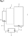
- FIG 1 schematically shows an exemplary embodiment of the monitoring arrangement 1 according to the invention.
- the monitoring arrangement 1 is used to monitor a system 2 which is controlled by a controller 3.
- the system 2 is connected to the controller 3 via a line 4.
- both the system 2 and the controller 3 have an interface 5.
- the monitoring arrangement 1 also has an optical sensor 6 with which objects within a monitoring area 7 are detected.
- the monitoring area 7 is dimensioned in such a way that it covers a danger area on the system 2.
- the controller 3 and the optical sensor 6 are connected via a serial transmission link 8 which is formed by a bus system.
- the controller 3 and the optical sensor 6 each have a serial interface 9.
- the monitoring arrangement 1 is used in the present case in the field of safety technology.
- the controller 3 is designed as a safe controller 3, ie the controller 3 has a fail-safe structure, for example with two computer units that monitor each other cyclically.
- the optical sensor 6 is also constructed as a safe optical sensor 6, which is achieved, for example, in that an evaluation unit for signal arrangement, which also has two computer units that monitor each other cyclically, is provided.
- serial transmission link 8 there is also a secure data transmission via the serial transmission link 8. This is achieved in that data transmitted via the serial transmission link 8 are protected by checksums.
- the controller 3 specifies configurations for the optical sensor 6 in that the controller 3 sends evaluation rules to the optical sensor 6. In accordance with the evaluation rules, preprocessing takes place in the optical sensor 6 or in parts of the optical sensor 6, partial results being generated during each preprocessing which are sent to the controller 3.
- the individual preprocessing that is carried out in the optical sensor 6 can take place offset in time, in parallel or in an interleaved manner.
- the preprocessing takes place in such a way that a data compression is achieved with the partial results obtained from individual sensor information from sensor components of the optical sensor 6; H. the partial results have a smaller data volume compared to the individual sensor information, so that the partial results can be transmitted to the controller 3 without significant delays.
- the controller 3 can flexibly adapt the functionality of the optical sensor 6, in particular its signal evaluation, to changing requirements.
- the partial results are further processed in the controller 3, in particular to generate an overall result. Since the partial results are only one represent a small amount of data, further processing can take place very quickly. Logical processing of the partial results advantageously takes place in the controller 3.
- a control signal for the system 2 is generated in the controller 3 as a function of the partial results. If the optical sensor 6 detects a dangerous intervention in the monitoring area 7, a shutdown command for the system 2 is generated as a control signal, so that the system 2 can no longer pose any dangers.
- FIG. 2 shows an embodiment of an optical sensor 6 in the form of a light curtain.
- the light curtain comprises a transmitter unit 10 with a number of transmitters 12 emitting light signals 11 at an edge of the monitoring area 7 and a receiver unit 13 with a number of receivers 14 corresponding to the number of transmitters 12.
- the transmitters 12 are controlled by a transmitter controller (not shown).
- the received signals of the receiver 14 are evaluated in the receiver unit 13.
- the transmitters 12 and receivers 14 are assigned in pairs opposite one another, so that when the monitoring area 7 is free, the light beams 11 of the transmitter 12 are guided unhindered to the assigned receiver 14.
- Each transmitter-receiver pair forms a beam axis.
- the transmitter-receiver pairs forming the beam axes are activated individually in pairs one after the other within predefined sequence cycles.
- the light curtain has eight beam axes.
- the light curtain can also have a different number of beam axes.
- the light curtain works according to the light barrier principle. Accordingly, an object is recognized by interrupting the light signals of at least one beam axis. These beam sub-calculations are recorded in that the received signals of the receivers 14 are each evaluated with a threshold value become. With the arrangement according to Figure 1 the light beams 11 of the three lower beam axes are interrupted by an object in the form of a box 15.
- the controller 3 can define three groups A, B, C of beam axes of the light curtain, with different preprocessing for generating partial results being carried out in the individual groups.
- Group A includes the top four beam axes of the light curtain.
- Group B includes the lower four beam axes of the light curtain.
- Group C includes all beam axes of the light curtain.
- the controller 3 prescribes evaluation rules in such a way that an object is considered recognized if at least one beam axis is only interrupted within one cycle. In this way, rapid object detection of particularly small objects such as a person's finger is reported in this sub-area of the light curtain. If such an object intervention is registered in the light curtain, this is output by group B to controller 3 as a partial result.
- the controller 3 prescribes evaluation rules in such a way that an object is considered to be recognized if an object interrupts at least 2 successive beams within several scanning cycles, in particular in consecutive scanning cycles. Such object registrations are also output as partial results in the controller 3.
- evaluation rules are specified in such a way that the monitored area 7 is considered free if, for example, B. no interruption of a beam axis is registered in a successive sequence cycle.
- edges of the box 15 can be recognized by recognizing a predetermined number of interrupted beam axes, the edge beams, ie the first and last interrupted beam axes, being at a certain distance.
- This information can also be output to the controller 3 as a partial result.
- the partial results are logically linked in the controller 3.
- an amplitude evaluation of the received signals of all receivers 14 can be specified so that the mean value, the maximum value and / or the minimum value is determined for these as the amplitude evaluation signal.
- These amplitude evaluation signals are output to the controller 3 as partial results.
- the controller 3 can set the threshold values for processing the received signals of the receivers 14 of the light curtain.
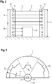
- Figure 3 shows an optical sensor 6 in the form of a surface distance sensor.
- the surface distance sensor has a measuring head 16 rotating about an axis of rotation.
- a distance sensor consisting of a transmitter 12 'and a receiver 14' is integrated in this measuring head 16.
- the distance measurements are carried out according to a pulse time-of-flight method.
- the light beams 11 ′ emitted by the transmitter 12 periodically sweep over a monitoring area 7 extending over an angular range of 180 °.
- the monitoring area 7 is divided into three sub-areas a, b, c, for which different evaluation rules are specified by the controller 3, so that different preprocessing operations are carried out for these sub-areas.
- a protective field boundary S a which delimits a first protective field , is specified for the partial area. If an object intrusion is registered within this protective field, this is output as a partial result to the controller 3, whereupon it generates a switch-off command for the system 2.
- a protective field boundary S b is specified for sub-area a, which limits a second protective field. If an object intrusion is registered within this protective field, this is output as a partial result to the controller 3, whereupon it generates a switch-off command for the system 2.
- a warning field boundary W c which delimits a warning field, is specified for sub-area c. If an object intervention is registered within this warning field, this is output as a partial result to the controller 3, whereupon it generates a warning signal.
- the protective fields in the sub-areas a, b and also the warning field can generally be activated via the controller 3 at different times.
Description
Die Erfindung betrifft eine Überwachungsanordnung für eine Anlage.The invention relates to a monitoring arrangement for a plant.
Derartige Überwachungsanordnungen weisen allgemein wenigstens einen optischen Sensor auf, der für Überwachungsaufgaben an der Anlage eingesetzt wird. Die Anlage kann in verschiedensten Ausprägungen ausgebildet sein. Insbesondere schließt der Begriff Anlage allgemein Arbeitsmittel wie Maschinen oder Roboter mit ein.Such monitoring arrangements generally have at least one optical sensor which is used for monitoring tasks on the system. The system can be designed in a wide variety of forms. In particular, the term system generally includes work equipment such as machines or robots.
Die Überwachungsanordnung umfasst neben einem optischen Sensor auch eine Steuerung, mittels derer der Betrieb der Anlage gesteuert wird. Zweckmäßig erfolgt eine Steuerung in Abhängigkeit der mit dem optischen Sensor generierten Ausgangssignale. Hierzu ist der optische Sensor mit der Anlage über die Steuerung verbunden.In addition to an optical sensor, the monitoring arrangement also includes a controller by means of which the operation of the system is controlled. Control is expediently carried out as a function of the output signals generated by the optical sensor. For this purpose, the optical sensor is connected to the system via the control.
Die Überwachungsanordnung wird insbesondere für Anwendungen im Bereich der Sicherheitstechnik eingesetzt. In diesem Fall wird mit dem optischen Sensor ein Überwachungsbereich überwacht, der von einem Gefahrenbereich an der Anlage gebildet ist. Wird mit dem optischen Sensor ein gefahrbringender Eingriff in dem Überwachungsbereich, beispielsweise durch eine Person, registriert, generiert der optische Sensor ein Ausgangssignal, das an die Steuerung übertragen wird, so dass diese die Anlage aus Sicherheitsgründen abschaltet.The monitoring arrangement is used in particular for applications in the field of safety technology. In this case, the optical sensor monitors a monitoring area that is formed by a danger area on the system. If a dangerous intervention in the monitoring area, for example by a person, is registered with the optical sensor, the optical sensor generates an output signal that is transmitted to the control so that it switches off the system for safety reasons.
Bei derartigen Überwachungsanordnungen erfolgt die komplette Signalauswertung von Sensorsignalen, die von Sensorkomponenten des optischen Sensors generiert werden, im optischen Sensor selbst. Das dadurch generierte Ausgangssignal kann dann von der Steuerung direkt zum Ansteuern der Anlage verwendet werden, insbesondere zum Abschalten der Anlage.In such monitoring arrangements, the complete signal evaluation takes place from sensor signals generated by sensor components of the optical sensor in the optical sensor itself. The output signal generated in this way can then be used by the controller directly to control the system, in particular to switch off the system.
Nachteilig bei derartigen Überwachungsanordnungen ist, dass eine Anpassung des optischen Sensors, insbesondere der Auswertung von Sensorsignalen, an sich verändernde Anforderungen nicht oder nur eingeschränkt möglich ist.A disadvantage of such monitoring arrangements is that an adaptation of the optical sensor, in particular the evaluation of sensor signals, to changing requirements is not possible or only possible to a limited extent.
Prinzipiell könnten die Sensorsignale des optischen Sensors unverarbeitet an die Steuerung ausgegeben werden, wo dann eine an die jeweiligen Anforderungen angepasste Auswertung möglich wäre. Dies ist jedoch deshalb nicht möglich, da die serielle Übertragungsstrecke keine hohen Datenmengen übertragen kann, so dass dadurch die Reaktionszeiten für die Auswertung von Sensorsignalen in der Steuerung unerwünscht hoch wären.In principle, the sensor signals of the optical sensor could be output unprocessed to the controller, where an evaluation adapted to the respective requirements would then be possible. However, this is not possible because the serial transmission path cannot transmit large amounts of data, so that the response times for the evaluation of sensor signals in the controller would be undesirably long.
Die
Weiterhin sind Modifikationsmittel zur gezielten Verstärkung oder Dämpfung des während des Selbsttests der Überwachungseinheit als Testsignal zugeführten analogen Messsignals vorgesehen.Modification means are also provided for the targeted amplification or attenuation of the analog measurement signal supplied as a test signal to the monitoring unit during the self-test.
Die
Die
Die in
Der Erfindung liegt die Aufgabe zugrunde, eine Überwachungsanordnung mit hoher Funktionalität bereitzustellen.The invention is based on the object of providing a monitoring arrangement with high functionality.
Zur Lösung dieser Aufgabe sind die Merkmale der unabhängigen Ansprüche vorgesehen. Vorteilhafte Ausführungsformen und zweckmäßige Weiterbildungen der Erfindung sind in den abhängigen Ansprüchen beschrieben.The features of the independent claims are provided to solve this problem. Advantageous embodiments and expedient developments of the invention are described in the dependent claims.
Die Erfindung betrifft eine Überwachungsanordnung für eine Anlage mit einer die Anlage steuernden Steuerung und mit einem eine Auswerteeinheit und Sensorkomponente aufweisenden optischen Sensor. Die Steuerung und der optische Sensor sind über eine serielle Übertragungsstrecke verbunden. Der optische Sensor ist mittels der Steuerung konfiguriert. In Abhängigkeit der Konfiguration in der Auswerteeinheit des optischen Sensors werden Vorverarbeitungen von Einzelsensorinformationen der Sensorkomponenten durchgeführt. Daraus werden Teilergebnisse generiert, welche an die Steuerung für eine Weiterverarbeitung übertragen werden.The invention relates to a monitoring arrangement for a system with a controller controlling the system and with an optical sensor having an evaluation unit and sensor components. The controller and the optical sensor are connected via a serial transmission link. The optical sensor is configured by means of the controller. Depending on the configuration in the evaluation unit of the optical sensor, preprocessing of individual sensor information from the sensor components is carried out. From this partial results are generated, which are transferred to the control for further processing.
Mit den erfindungsgemäßen Überwachungsanordnungen bzw. mit einem Verfahren zum Betrieb einer solchen Überwachungsanordnung wird eine flexible Überwachungsfunktion für eine Anlage bereitgestellt, wobei die Anlage auch als Maschine, Roboter und dergleichen ausgebildet sein kann.With the monitoring arrangements according to the invention or with a method for operating such a monitoring arrangement, a flexible monitoring function is provided for a system, wherein the system can also be designed as a machine, robot and the like.
Die Überwachungsanordnung weist generell eine Steuerung auf, an welche im einfachsten Fall ein optischer Sensor über eine serielle Übertragungsstrecke angeschlossen ist. Generell können auch mehrere optische Sensoren an die Steuerung angeschlossen sein.The monitoring arrangement generally has a controller to which, in the simplest case, an optical sensor is connected via a serial transmission path. In general, several optical sensors can also be connected to the controller.
Die Überwachungsanordnung kann insbesondere im Bereich der Sicherheitstechnik eingesetzt werden, insbesondere im Bereich des Personenschutzes.The monitoring arrangement can be used in particular in the field of security technology, in particular in the field of personal protection.
In diesem Fall sind vorteilhaft die Steuerung als sichere Steuerung und der optische Sensor als sicherer optischer Sensor ausgebildet.In this case, the controller is advantageously designed as a safe controller and the optical sensor as a safe optical sensor.
Eine sichere Steuerung weist generell einen fehlersicheren Aufbau, insbesondere in Form zweier sich gegenseitig zyklisch überwachender Rechnereinheiten auf. Ein sicherer Sensor weist einen entsprechenden fehlsicheren Aufbau mit einer redundant aufgebauten, zweikanaligen Auswerteeinheit auf.A safe control generally has a fail-safe structure, in particular in the form of two computer units that monitor each other cyclically. A safe sensor has a corresponding fail-safe structure with a redundant, two-channel evaluation unit.
Um die Sicherheitsanforderungen im Bereich der Sicherheitstechnik zu erfüllen, erfolgt zudem auch über die serielle Übertragungsstrecke eine sichere Datenübertragung.In order to meet the safety requirements in the area of safety technology, secure data transmission also takes place via the serial transmission path.
Hierzu sind vorteilhaft über die serielle Übertragungsstrecke übertragene Informationen durch Prüfsummen abgesichert.For this purpose, information transmitted via the serial transmission path is advantageously secured by checksums.
Durch diese Absicherung mit Prüfsummen können einerseits Übertragungsfehler bei der Übertragung von Information über die serielle Übertragungsstrecke aufgedeckt werden. Weiterhin können auch Fehler in der Abspeicherung von Informationen im optischen Sensor bzw. in der Steuerung aufgedeckt werden.On the one hand, this safeguarding with checksums can reveal transmission errors when transmitting information over the serial transmission path. Furthermore, errors in the storage of information in the optical sensor or in the controller can also be detected.
Die serielle Übertragungsstrecke ist vorteilhaft von einem Bussystem, insbesondere einem Feldbus gebildet, wobei die Steuerung und der optische Sensor hier geeignete Schnittstellen aufweisen. Ein Beispiel für ein derartiges Bussystem ist IO-Link Safety.The serial transmission path is advantageously formed by a bus system, in particular a field bus, the controller and the optical sensor here having suitable interfaces. One example of such a bus system is IO-Link Safety.
Bei einem Einsatz im Bereich der Sicherheitstechnik wird generell mit dem optischen Sensor ein Gefahrenbereich an der Anlage überwacht. Aus den im optischen Sensor generierten Teilergebnissen bei der Objekterkennung wird dann in der Steuerung ein Steuersignal für die Anlage generiert. Das Steuersignal ist dann als Abschaltbefehl für die Anlage ausgebildet, wenn mit dem optischen Sensor ein gefahrbringender Eingriff in den Gefahrenbereich registriert wird. Durch dieses Abschalten der Anlage werden gefahrbringende Zustände, insbesondere für Personen, vermieden.When used in the field of safety technology, a hazardous area on the system is generally monitored with the optical sensor. A control signal for the system is then generated in the controller from the partial results generated in the optical sensor during object detection. The control signal is then designed as a shutdown command for the system when a dangerous intervention in the danger area is registered with the optical sensor. By switching off the system in this way, dangerous conditions, especially for people, are avoided.
Bei der erfindungsgemäßen Überwachungsanordnung kann der optische Sensor ein Lichttaster oder Distanzsensor sein.In the monitoring arrangement according to the invention, the optical sensor can be a light scanner or a distance sensor.
In beiden Fällen weist der optische Sensor als Sensorkomponente einen Lichtstrahlen emittierenden Sender und einen Lichtstrahlen empfangenden Empfänger auf. Der Sender emittiert dabei die Lichtstrahlen in eine vorgegebene Richtung, so dass mit derartigen optischen Sensoren nur ein eng begrenzter Raumbereich überwacht werden kann.In both cases, the optical sensor has a transmitter that emits light beams and a receiver that receives light beams as the sensor component. The transmitter emits the light beams in a predetermined direction, so that only a narrowly limited spatial area can be monitored with such optical sensors.
Um eine Überwachung innerhalb eines ausgedehnten, insbesondere flächigen Überwachungsbereichs zu ermöglichen, können diese optischen Sensoren derart weitergebildet sein, dass diese eine Mehrfachanordnung von Sendern und Empfängern aufweisen und damit die Struktur eines tastenden Lichtvorhangs aufweisen.In order to enable monitoring within an extensive, in particular flat, monitoring area, these optical sensors can be developed in such a way that they have a multiple arrangement of transmitters and receivers and thus have the structure of a scanning light curtain.
Alternativ kann der optische Sensor ein scannendes System sein.Alternatively, the optical sensor can be a scanning system.
In diesem Fall überstreichen die Lichtstrahlen des Senders periodisch innerhalb vorgegebener Abtastzyklen einen flächigen Überwachungsbereich. Die Ablenkbewegung der Lichtstrahlen kann dadurch erzeugt werden, dass einem stationär angeordneten Sender eine sich drehende oder allgemein sich bewegende Ablenkeinheit nachgeordnet ist, mittels derer die Lichtstrahlen periodisch abgelenkt werden. Alternativ können der Sender und der Empfänger des optischen Sensors in einem rotierenden Messkopf integriert sein.In this case, the light beams from the transmitter periodically sweep over a flat monitoring area within specified scanning cycles. The deflection movement of the light beams can be generated in that a stationary transmitter is followed by a rotating or generally moving deflection unit, by means of which the light beams are periodically deflected. Alternatively, the transmitter and the receiver of the optical sensor can be integrated in a rotating measuring head.
Weiterhin kann der optische Sensor als Lichtvorhang ausgebildet sein.Furthermore, the optical sensor can be designed as a light curtain.
Der Lichtvorhang weist eine Sendereinheit mit einer Anzahl von Lichtstrahlen emittierenden Sendern und eine Empfängereinheit mit einer Anzahl von Lichtstrahlen empfangenden Empfängern auf. Der Lichtvorhang kann nach dem Lichtschrankenprinzip arbeiten. In diesem Fall sind die Sendereinheit und die Empfängereinheit an gegenüberliegenden Rändern eines Überwachungsbereichs so angeordnet, dass bei keinem Überwachungsbereich die Lichtstrahlen der Sender jeweils ungehindert auf einen zugeordneten Empfänger auftreffen. Alternativ kann der Lichtvorhang nach dem Reflexionslichtschrankenprinzip arbeiten. In diesem Fall befinden sich die Sendereinheit und Empfängereinheit am selben Rand des Überwachungsbereichs, wobei am gegenüberliegenden Rand des Überwachungsbereichs ein Reflektor angeordnet ist. Bei freiem Überwachungsbereich werden dann von einem Sender emittierte Lichtstrahlen ungehindert zum Reflektor geführt und von dort ungehindert zu dem jeweils zugeordneten Empfänger reflektiert.The light curtain has a transmitter unit with a number of transmitters emitting light beams and a receiver unit with a number of receivers that receive light beams. The light curtain can work according to the light barrier principle. In this case, the transmitter unit and the receiver unit are arranged on opposite edges of a monitored area in such a way that the light beams of the transmitters do not strike an assigned receiver unhindered in any of the monitored areas. Alternatively, the light curtain can work according to the reflection light barrier principle. In this case, the transmitter unit and receiver unit are located on the same edge of the monitoring area, a reflector being arranged on the opposite edge of the monitoring area. When the monitoring area is free, light beams emitted by a transmitter are then guided unhindered to the reflector and reflected from there unhindered to the respectively assigned receiver.
Bei beiden Varianten erfolgt eine Objekterkennung dadurch, dass ein im Überwachungsbereich befindliches Objekt die Lichtstrahlen wenigstens eines Senders wenigstens teilweise unterbricht. Diese Unterbrechungen werden dadurch erfasst, dass die Amplituden der Empfangssignale der einzelnen Empfänger jeweils mit einem Schwellwert bewertet werden. Vorteilhaft werden zur Objektdetektion die einzelnen Strahlenachsen bildenden Sender-Empfängerpaare periodisch einzeln nacheinander innerhalb vorgegebener Abstandszyklen aktiviert.In both variants, object detection takes place in that an object located in the monitoring area at least partially interrupts the light beams of at least one transmitter. These interruptions are recorded by evaluating the amplitudes of the received signals of the individual receivers with a threshold value. For object detection, the transmitter-receiver pairs forming the individual beam axes are advantageously activated periodically one after the other within predetermined distance cycles.
Der Grundgedanke der Erfindung besteht darin, dass die Steuerung für den optischen Sensor eine Konfiguration vorgibt, wobei der optische Sensor entsprechend dieser Konfiguration Vorverarbeitungen derart durchführt, dass aus Einzelsensorinformationen von Sensorkomponenten Teilergebnisse gewonnen und an die Steuerung übertragen werden, wo diese weiterverarbeitet werden.The basic idea of the invention is that the controller specifies a configuration for the optical sensor, the optical sensor performing preprocessing in accordance with this configuration in such a way that partial results are obtained from individual sensor information from sensor components and transmitted to the controller, where they are further processed.
Die Weiterverarbeitung der Teilergebnisse kann in der Steuerung dadurch erfolgen, dass aus diesen Teilergebnissen ein Gesamtergebnis generiert wird. Vorteilhaft kann als Gesamtergebnis ein Steuersignal für die Anlage generiert werden. Insbesondere dann, wenn die Auswertung der Teilergebnisse des optischen Sensors ergibt, dass ein gefahrbringender Zustand vorliegt, wird als Steuerbefehl ein Abschaltbefehl für die Anlage generiert.The further processing of the partial results can take place in the control by generating an overall result from these partial results. A control signal for the system can advantageously be generated as the overall result. In particular, when the evaluation of the partial results of the optical sensor shows that a dangerous state is present, a shutdown command for the system is generated as a control command.
Vorteilhaft erfolgt in der Steuerung eine logische Verarbeitung der Teilergebnisse des optischen Sensors. Im einfachsten Fall erfolgt eine logische Verknüpfung von mehreren zeitgleich vorliegenden Teilergebnissen. Weiterhin können die Vorverarbeitungen auch zu unterschiedlichen Zeiten erfolgen, so dass die Teilergebnisse zeitversetzt in der Steuerung vorliegen. In diesem Fall kann die logische Verarbeitung derart erweitert sein, dass kausale Abhängigkeiten der Teilergebnisse gebildet werden.A logical processing of the partial results of the optical sensor advantageously takes place in the control. In the simplest case, several partial results that are available at the same time are logically linked. Furthermore, the preprocessing can also take place at different times, so that the partial results are available in the controller with a time delay. In this case, the logical processing can be extended in such a way that causal dependencies of the partial results are formed.
Ein erster wesentlicher Vorteil der Erfindung besteht somit darin, dass die Steuerung die Endverarbeitung von Teilergebnissen des optischen Sensors übernimmt, um dadurch ein Gesamtergebnis zu generieren, das insbesondere ein Steuersignal für die zu steuernde Anlage sein kann. Die Steuerung kann somit eine flexible Anpassung an Anforderungen der Anlage, insbesondere an Anforderungen für eine Überwachung der Anlage vornehmen, indem sie für den optischen Sensor eine hierzu passende Konfiguration vorgibt, so dass der optische Sensor passende Teilergebnisse generiert, die dann die Steuerung zu einem für die Anforderungen passenden Gesamtergebnis verarbeitet.A first essential advantage of the invention is thus that the control takes over the final processing of partial results of the optical sensor in order to generate an overall result, which can in particular be a control signal for the system to be controlled. The controller can thus make a flexible adaptation to requirements of the system, in particular to requirements for monitoring the system, by specifying a configuration suitable for this for the optical sensor, so that the optical sensor generates suitable partial results, which the controller then converts to one for the overall result that matches the requirements is processed.
Ein weiterer wesentlicher Vorteil der Erfindung besteht darin, dass mit den im optischen Sensor durchgeführten Vorverarbeitungen eine Datenverdichtung erfolgt, da eine Vielzahl von Einzelsensorinformationen zu jeweils einem Teilergebnis zusammengefasst wird. Diese Teilergebnisse, die nur ein geringes Datenvolumen beanspruchen, können über die serielle Übertragungsstrecke schnell, d. h. ohne nennenswerte Verzögerung, an die Steuerung übertragen werden. Die Steuerung der Gesamtergebnisse aus den Teilergebnissen des optischen Sensors kann somit mit kurzen Reaktionszeiten erfolgen.Another essential advantage of the invention is that the preprocessing carried out in the optical sensor is used to compress data, since a large number of individual sensor items of information are each combined to form a partial result. These partial results, which only require a small volume of data, can be transferred quickly via the serial transmission link, i. H. can be transmitted to the controller without any significant delay. The control of the overall results from the partial results of the optical sensor can thus take place with short reaction times.
Gemäß einer vorteilhaften Ausführungsform ist der optische Sensor dadurch konfiguriert, dass von der Steuerung Auswerteregeln für die Durchführung der Vorverarbeitung an diesen übertragen werden.According to an advantageous embodiment, the optical sensor is configured in that evaluation rules for carrying out the preprocessing are transmitted to it from the controller.
Mit den Auswerteregeln kann die Funktionsweise, insbesondere die Art der Signalauswertung, vorgegeben werden. Dabei können einerseits die Funktionalitäten der einzelnen Sensorkomponenten vorgegeben werden. Weiterhin kann vorgegeben werden, welche Sensorkomponenten miteinander kombiniert werden, um für ein bei einer Vorverarbeitung zu generierendes Teilergebnis beizutragen. Mittels dieser Auswerteregel kann die Steuerung eine flexible und schnelle Anpassung der Funktion des optischen Sensors vornehmen und so gezielt auf sich ändernde Anforderungen reagieren.The mode of operation, in particular the type of signal evaluation, can be specified with the evaluation rules. On the one hand, the functionalities of the individual sensor components can be specified. Furthermore, it can be specified which sensor components are combined with one another in order to contribute to a partial result to be generated during preprocessing. Using this evaluation rule, the controller can adapt the function of the optical sensor flexibly and quickly and thus react in a targeted manner to changing requirements.
Insbesondere können damit unterschiedliche Konfigurationen zeitabhängig von der Steuerung vorgeben werden. Dadurch ist es möglich, dass im optischen Sensor unterschiedliche Vorverarbeitungen zeitlich parallel, hintereinander oder überlappend durchgeführt werden.In particular, different configurations can thus be specified by the controller as a function of time. This makes it possible for different preprocessing operations to be carried out in parallel, one behind the other or in an overlapping manner in the optical sensor.
Die zeitliche Abfolge der im optischen Sensor durchführenden Vorverarbeitung kann damit von der Steuerung an die jeweiligen Anforderungen angepasst werden.The time sequence of the preprocessing carried out in the optical sensor can thus be adapted by the control to the respective requirements.
Gemäß einer vorteilhaften Ausführungsform ist im optischen Sensor für einzelne Vorverarbeitungen jeweils eine Gruppe von Sensorkomponenten zusammengefasst.According to an advantageous embodiment, a group of sensor components is combined in the optical sensor for individual preprocessing.
Diese Ausführungsform eignet sich insbesondere für optische Sensoren in Form von Lichtvorhängen. Dort können durch Vorgabe von Auswerteregeln einzelne Gruppen von zusammengehörenden Sendern und Empfängern zusammengefasst werden, wobei mit diesen Gruppen unterschiedliche zusammenhängende oder auch nicht zusammenhängende Bereiche überwacht werden.This embodiment is particularly suitable for optical sensors in the form of light curtains. There, by specifying evaluation rules, individual groups of associated senders and receivers can be combined, with these groups being used to monitor different related or non-related areas.
Durch eine solche Unterteilung der Sensorkomponenten in Gruppen kann beispielsweise die Signalauswertung derart optimiert werden, dass nicht ständig alle Sensorkomponenten zur Signalauswertung herangezogen werden, sondern jeweils nur die für eine Überwachungsfunktion relevanten Sensorkomponenten.By dividing the sensor components into groups in this way, for example, the signal evaluation can be optimized in such a way that not all sensor components are constantly used for signal evaluation, but only the sensor components relevant for a monitoring function.
Beispielsweise können bei einem Lichtvorhang, der zu einer Objektverfolgung von Objekten im Überwachungsbereich eingesetzt wird, bei in der Steuerung vorhandenen Bahnen von Objekten durch zeitabhängige Vorgabe geeigneter Auswerteregeln für Gruppen von Sender-Empfängerpaare immer nur die Bereiche des Lichtvorhangs aktiviert werden, wo sich das Objekt gerade aufhält, um dieses dann beispielsweise in seiner Geometrie zu erfassen.For example, in the case of a light curtain that is used to track objects in the monitoring area, only those areas of the light curtain where the object is currently located can be activated by means of time-dependent specification of suitable evaluation rules for groups of transmitter-receiver pairs stops in order to then capture this, for example, in its geometry.
Gemäß einer weiteren vorteilhaften Ausführungsform wird der optische Sensor zur Überwachung eines Überwachungsbereichs ausgebildet. Mit einer Vorverarbeitung wird ein Teilbereich des Überwachungsbereichs erfasst.According to a further advantageous embodiment, the optical sensor is designed to monitor a monitored area. A sub-area of the monitored area is recorded with preprocessing.
Bei einem Lichtvorhang ist eine Unterteilung des Überwachungsbereichs in Teilbereiche dadurch möglich, dass unterschiedliche Gruppen von Sender-Empfängerpaaren zusammengefasst werden und für diese separate Vorverarbeitungen zur Generierung von Teilergebnissen durchgeführt werden.In the case of a light curtain, the monitored area can be subdivided into partial areas in that different groups of transmitter-receiver pairs are combined and separate preprocessing is carried out for these in order to generate partial results.
Bei einem optischen Sensor in Form eines scannenden Systems werden die Lichtstrahlen des Senders innerhalb eines Winkelbereichs geführt, um den Überwachungsbereich abzutasten. Teilbereiche des Überwachungsbereichs werden dann durch Teilbereiche dieses Winkelbereichs vorgegeben, so dass in diesem separate Vorverarbeitungen zur Generierung von Teilergebnissen durchgeführt werden können.In the case of an optical sensor in the form of a scanning system, the light beams from the transmitter are guided within an angular range in order to scan the monitored area. Subareas of the monitored area are then specified by subareas of this angular area, so that separate preprocessing for the generation of partial results can be carried out in this area.
Gemäß einer vorteilhaften Ausführungsform ist durch Auswerteregeln einer Vorverarbeitung der Modus einer Objekterfassung vorgegeben.According to an advantageous embodiment, the mode of object detection is specified by evaluation rules for preprocessing.
Insbesondere kann durch Auswerteeinheiten die Art der Signalauswertung für eine Objekterfassung vorgegeben werden.In particular, the type of signal evaluation for object detection can be specified by evaluation units.
Beispielsweise kann eine räumliche Filterfunktion in Form einer reduzierten Auflösung des optischen Sensors vorgegeben werden. Bei einem scannenden Distanzsensor kann beispielsweise eine Mindestgröße für ein zu detektierendes Objekt vorgegeben werden. Bei einem Lichtvorhang kann eine reduzierte Auflösung dadurch erhalten werden, dass für eine Objektdetektion nicht nur die Unterbereiche einer Strahlachse, sondern die Unterbrechung mehrerer aufeinanderfolgender Strahlachsen gefordert wird.For example, a spatial filter function can be specified in the form of a reduced resolution of the optical sensor. In the case of a scanning distance sensor, for example, a minimum size can be specified for an object to be detected. In the case of a light curtain, a reduced resolution can be obtained in that, for an object detection, not only the sub-areas of a beam axis, but the interruption of several consecutive beam axes is required.
Weiterhin kann eine zeitliche Filterfunktion derart vorgegeben werden, dass der optische Sensor das jeweilige Objekt nicht nur während eines Abtastzyklus, sondern während mehreren aufeinanderfolgenden Abtastzyklen erkennt.Furthermore, a temporal filter function can be specified in such a way that the optical sensor detects the respective object not only during one scanning cycle, but rather during several consecutive scanning cycles.
Weiterhin kann auch eine Kontur- oder Größenerkennung von Objekten vorgenommen werden. Bei einem Lichtvorhang erfolgt dies dadurch, dass zur Erkennung einer Kontur eine vorgegebene Anzahl unterbrochener Strahlachsen gefordert sind, wobei zur Bestimmung der Lage und Größe Randstrahlen bildende Strahlachsen erfasst werden, die den Übergang zwischen unterbrochenen und nicht unterbrochenen Strahlachsen bilden.Furthermore, the contour or size of objects can also be recognized. In the case of a light curtain, this takes place in that a predetermined number of interrupted beam axes are required to recognize a contour, with beam axes forming edge beams being detected to determine the position and size, which form the transition between interrupted and uninterrupted beam axes.
Bei einer Zusammenfassung von Sensorkomponenten des optischen Sensors zu einzelnen Gruppen, bzw. einer Einteilung des Überwachungsbereichs in verschiedene Teilbereiche, können für die unterschiedlichen Gruppen bzw. Teilbereiche unterschiedliche Vorverarbeitungen durchgeführt werden, insbesondere durch Vorgabe unterschiedlicher Filterfunktionen.When combining sensor components of the optical sensor into individual groups or dividing the monitored area into different sub-areas, different preprocessing can be carried out for the different groups or sub-areas, in particular by specifying different filter functions.
Besonders vorteilhaft wird durch Auswerteregeln einer Vorverarbeitung eine Amplitudenbewertung vorgegeben.An amplitude evaluation is particularly advantageously predefined by evaluation rules for preprocessing.
Mit den durchgeführten Amplitudenbewertungen werden Statusinformationen über den optischen Sensor gewonnen, die in die Steuerung zurückgelesen werden. Anhand dieser Statusinformationen kann beispielsweise die Steuerung kontrollieren, ob der optische Sensor fehlerfrei arbeitet. Dieser Status des optischen Sensors kann in der Steuerung mit geeigneten Anzeigemitteln angezeigt werden. Weiterhin kann die Steuerung in Abhängigkeit der Ergebnisse der Amplitudenbewertungen Einstellungen des optischen Sensors vornehmen, indem sie über die serielle Überwachungsstrecke entsprechende Einstellbefehle an den optischen Sensor sendet.With the amplitude evaluations carried out, status information is obtained about the optical sensor, which is read back into the control. Using this status information, the controller can, for example, check whether the optical sensor is working properly. This status of the optical sensor can be displayed in the control with suitable display means. Furthermore, the control can make settings of the optical sensor as a function of the results of the amplitude evaluations by sending appropriate setting commands to the optical sensor via the serial monitoring path.
Besonders vorteilhaft wird die Amplitudenbewertung bei optischen Sensoren in Form von Lichtvorhängen durchgeführt. Je nachdem, ob gemäß einer Auswerteregel eine Vorverarbeitung für einen genannten Lichtvorhang oder nur für eine Gruppe von Strahlachsen durchgeführt wird, werden vorzugsweise über mehrere Abtastzyklen die Amplituden der Empfangssignale erfasst. Aus diesen Amplituden werden als Amplitudenbewertungssignale der arithmetische Mittelwert und/oder der geometrische Mittelwert und/oder die Maximalamplitude und/oder die Minimalamplitude bestimmt und als Teilergebnis vom optischen Sensor an die Steuerung übertragen.In the case of optical sensors, the amplitude evaluation is carried out particularly advantageously in the form of light curtains. Depending on whether preprocessing for a named light curtain or only for a group of beam axes is carried out according to an evaluation rule, the amplitudes of the received signals are preferably recorded over several scanning cycles. From these amplitudes, the arithmetic mean value and / or the geometric mean value and / or the maximum amplitude and / or the minimum amplitude are determined as amplitude evaluation signals and transmitted as a partial result from the optical sensor to the controller.
Abhängig von diesem Amplitudenbewertungssignal können dann beispielsweise durch die Steuerung die Schwellwerte des Lichtvorhangs, mit denen die Empfangssignale bewertet werden, vorgegeben werden.Depending on this amplitude evaluation signal, the control can then, for example, specify the threshold values of the light curtain with which the received signals are evaluated.
Die Erfindung wird im Folgenden anhand der Zeichnungen erläutert. Es zeigen:
- Figur 1:
- Schematische Darstellung eines Ausführungsbeispiels der erfindungsgemäßen Überwachungsanordnung.
- Figur 2:
- Darstellung eines optischen Sensors in Form eines Lichtvorhangs für die
Überwachungsanordnung gemäß Figur 1 . - Figur 3:
- Darstellung eines optischen Sensors in Form eines Flächendistanzsensors für die Überwachungsanordnung.
- Figure 1:
- Schematic representation of an exemplary embodiment of the monitoring arrangement according to the invention.
- Figure 2:
- Representation of an optical sensor in the form of a light curtain for the monitoring arrangement according to FIG
Figure 1 . - Figure 3:
- Representation of an optical sensor in the form of a surface distance sensor for the monitoring arrangement.
Die Überwachungsanordnung 1 weist weiterhin einen optischen Sensor 6 auf, mit dem Objekte innerhalb eines Überwachungsbereichs 7 erfasst werden. Der Überwachungsbereich 7 ist so dimensioniert, dass dieser einen Gefahrenbereich an der Anlage 2 abdeckt.The
Die Steuerung 3 und der optische Sensor 6 sind über eine serielle Übertragungsstrecke 8, die von einem Bussystem gebildet ist, verbunden. Hierzu weisen die Steuerung 3 und der optischen Sensor 6 jeweils eine serielle Schnittstelle 9 auf.The
Die Überwachungsanordnung 1 wird im vorliegenden Fall im Bereich der Sicherheitstechnik eingesetzt. Hierzu ist die Steuerung 3 als sichere Steuerung 3 ausgebildet, d. h. die Steuerung 3 weist einen fehlersicheren Aufbau auf, beispielsweise mit zwei sich gegenseitig zyklisch überwachenden Rechnereinheiten. Ebenso ist der optische Sensor 6 als sicherer optischer Sensor 6 aufgebaut, was beispielsweise dadurch erreicht wird, dass eine Auswerteeinheit zur Signalanordnung, welche ebenfalls zwei sich gegenseitig zyklisch überwachenden Rechnereinheiten aufweist, vorgesehen ist.The
Schließlich erfolgt auch eine sichere Datenübertragung über die serielle Übertragungsstrecke 8. Dies wird dadurch erreicht, dass über die serielle Übertragungsstrecke 8 übertragene Daten durch Prüfsummen abgesichert sind.Finally, there is also a secure data transmission via the
Erfindungsgemäß gibt die Steuerung 3 für den optischen Sensor 6 Konfigurationen vor, indem die Steuerung 3 an den optischen Sensor 6 Auswerteregeln sendet. Entsprechend der Auswerteregeln erfolgt im optischen Sensor 6 oder in Teilen des optischen Sensors 6 eine Vorverarbeitung, wobei bei jeder Vorverarbeitung Teilergebnisse generiert werden, die an die Steuerung 3 gesendet werden.According to the invention, the
Die einzelnen Vorverarbeitungen, die im optischen Sensor 6 durchgeführt werden, können zeitlich versetzt, parallel oder verschachtelt ablaufen.The individual preprocessing that is carried out in the optical sensor 6 can take place offset in time, in parallel or in an interleaved manner.
In jedem Fall erfolgen die Vorverarbeitungen derart, dass mit den aus Einzelsensorinformationen von Sensorkomponenten des optischen Sensors 6 gewonnenen Teilergebnisse eine Datenverdichtung erzielt wird, d. h. die Teilergebnisse weisen im Vergleich zu den Einzelsensorinformationen ein geringeres Datenvolumen auf, so dass die Teilergebnisse ohne nennenswerte Verzögerungen an die Steuerung 3 übertragen werden können.In any case, the preprocessing takes place in such a way that a data compression is achieved with the partial results obtained from individual sensor information from sensor components of the optical sensor 6; H. the partial results have a smaller data volume compared to the individual sensor information, so that the partial results can be transmitted to the
Durch die Vorgabe der Auswerteregeln kann die Steuerung 3 flexibel die Funktionalität des optischen Sensors 6, insbesondere dessen Signalauswertung, an sich verändernde Anforderungen anpassen.By specifying the evaluation rules, the
In der Steuerung 3 erfolgt eine Weiterverarbeitung der Teilergebnisse, insbesondere zur Generierung eines Gesamtergebnisses. Da die Teilergebnisse nur eine geringe Datenmenge darstellen, kann die Weiterverarbeitung sehr schnell erfolgen. Vorteilhaft erfolgt in der Steuerung 3 eine logische Verarbeitung der Teilergebnisse.The partial results are further processed in the
Insbesondere wird in der Steuerung 3 in Abhängigkeit der Teilergebnisse ein Steuersignal für die Anlage 2 generiert. Wird mit dem optischen Sensor 6 ein gefahrbringender Eingriff in den Überwachungsbereich 7 festgestellt, wird als Steuersignal ein Abschaltbefehl für die Anlage 2 erzeugt, so dass von der Anlage 2 keine Gefahren mehr ausgehen können.In particular, a control signal for the
Die Sender 12 und Empfänger 14 sind paarweise gegenüberliegend zugeordnet, so dass bei freiem Überwachungsbereich 7 die Lichtstrahlen 11 des Senders 12 ungehindert zum zugeordneten Empfänger 14 geführt sind. Jedes Sender-Empfängerpaar bildet eine Strahlachse. Durch eine optische Synchronisierung werden die die Strahlachsen bildenden Sender-Empfängerpaare innerhalb vorgegebener Ablaufzyklen paarzyklisch einzeln nacheinander aktiviert.The
Im vorliegenden Fall weist der Lichtvorhang acht Strahlachsen auf. Natürlich kann der Lichtvorhang auch eine andere Anzahl von Strahlachsen aufweisen.In the present case, the light curtain has eight beam axes. Of course, the light curtain can also have a different number of beam axes.
Der Lichtvorhang arbeitet nach dem Lichtschrankenprinzip. Demzufolge erfolgt eine Objekterkennung durch eine Unterbrechung der Lichtsignale wenigstens einer Strahlachse. Diese Strahlenunterberechnungen werden dadurch erfasst, dass die Empfangssignale der Empfänger 14 jeweils mit einem Schwellwert bewertet werden. Bei der Anordnung gemäß
Durch Vorgabe von Auswerteregeln kann die Steuerung 3 drei Gruppen A, B, C von Strahlachsen des Lichtvorhangs definieren, wobei in den einzelnen Gruppen unterschiedliche Vorverarbeitungen zur Generierung von Teilergebnissen durchgeführt werden. Die Gruppe A umfasst die oberen vier Strahlachsen des Lichtvorhangs. Die Gruppe B umfasst die unteren vier Strahlachsen des Lichtvorhangs. Die Gruppe C umfasst alle Strahlachsen des Lichtvorhangs.By specifying evaluation rules, the
Für die Gruppe B werden von der Steuerung 3 Auswerteregeln derart vorgegeben, dass ein Objekt als erkannt gilt, wenn nur innerhalb eines Zyklus wenigstens eine Strahlachse unterbrochen ist. Damit wird in diesem Teilbereich des Lichtvorhangs eine schnelle Objektdetektion von insbesondere kleinen Objekten wie einem Finger einer Person gemeldet. Wird ein solcher Objekteingriff im Lichtvorhang registriert, wird dies von der Gruppe B als Teilergebnis an die Steuerung 3 ausgegeben.For group B, the
Für die Gruppe A werden von der Steuerung 3 Auswerteregeln derart vorgegeben, dass ein Objekt als erkannt gilt, wenn innerhalb mehrerer Abtastzyklen, insbesondere bei Abtastzyklen hintereinander, ein Objekt wenigstens 2 aufeinanderfolgende Strahlen unterbricht. Auch derartige Objekteerfassungen werden als Teilergebnis in die Steuerung 3 ausgegeben.For group A, the
Für die Gruppe C werden Auswerteregeln derart vorgegeben, dass der Überwachungsbereich 7 dann als frei gilt, wenn z. B. in einem aufeinanderfolgenden Ablaufzyklus keine Unterbrechung einer Strahlachse registriert wird.For group C, evaluation rules are specified in such a way that the monitored
Weiterhin können die Kanten der Kiste 15 erkannt werden, indem eine vorgegebene Anzahl unterbrochener Strahlachsen erkannt wird, wobei die Randstrahlen, d. h. die erste und letzte unterbrochenen Strahlachse einen bestimmten Abstand aufweisen.Furthermore, the edges of the
Auch diese Informationen können als Teilergebnis an die Steuerung 3 ausgegeben werden.This information can also be output to the
In der Steuerung 3 werden die Teilergebnisse logisch verknüpft.The partial results are logically linked in the
Als Ergebnis dieser Verknüpfung wird z. B. in der Steuerung 3 ein Abschaltbefehl für die Anlage 2 dann generiert, wenn entweder für die Gruppe A ein Objekteingriff registriert wird, oder für die Gruppe B ein Objekteingriff registriert wird, dieser aber gemäß der Auswertung der Gruppe C nicht vom Einfahren der nicht sicherheitskritischen Kiste 15 in den Überwachungsbereich 7 erfasst wird.As a result of this link z. B. in the
Schließlich kann für die Gruppe C durch Vorgabe von Auswerteregeln eine Amplitudenbewertung der Empfangssignale der aller Empfänger 14 vorgegeben werden, dass für diese als Amplitudenbewertungssignal der Mittelwert, der Maximalwert und/oder der Minimalwert bestimmt wird. Diese Amplitudenbewertungssignale werden als Teilergebnisse an die Steuerung 3 ausgegeben. In Abhängigkeit hiervon kann die Steuerung 3 die Schwellwerte zur Bearbeitung der Empfangssignale der Empfänger 14 des Lichtvorhangs einstellen.Finally, for group C, by specifying evaluation rules, an amplitude evaluation of the received signals of all
Der Überwachungsbereich 7 ist in drei Teilbereiche a, b, c unterteilt, für welche von der Steuerung 3 unterschiedliche Auswerteregeln vorgegeben werden, so dass für diese Teilbereiche unterschiedliche Vorverarbeitungen durchgeführt werden.The
So wird für den Teilbereich eine Schutzfeldgrenze Sa vorgegeben, die ein erstes Schutzfeld begrenzt. Wird innerhalb dieses Schutzfelds ein Objekteingriff registriert, wird dies als Teilergebnis an die Steuerung 3 ausgegeben, worauf diese einen Abschaltbefehl für die Anlage 2 erzeugt.A protective field boundary S a, which delimits a first protective field , is specified for the partial area. If an object intrusion is registered within this protective field, this is output as a partial result to the
Entsprechend wird für den Teilbereich a eine Schutzfeldgrenze Sb vorgegeben, die ein zweites Schutzfeld begrenzt. Wird innerhalb dieses Schutzfeldes ein Objekteingriff registriert, wird dies als Teilergebnis an die Steuerung 3 ausgegeben, worauf diese einen Abschaltbefehl für die Anlage 2 erzeugt.Correspondingly, a protective field boundary S b is specified for sub-area a, which limits a second protective field. If an object intrusion is registered within this protective field, this is output as a partial result to the
Für den Teilbereich c wird eine Warnfeldgrenze Wc vorgegeben, die ein Warnfeld begrenzt. Wird innerhalb dieses Warnfelds ein Objekteingriff registriert, wird dies als Teilergebnis an die Steuerung 3 ausgegeben, worauf diese ein Warnsignal generiert.A warning field boundary W c , which delimits a warning field, is specified for sub-area c. If an object intervention is registered within this warning field, this is output as a partial result to the
Die Schutzfelder in den Teilbereichen a, b und auch das Warnfeld können allgemein über die Steuerung 3 zu unterschiedlichen Zeiten aktiviert sein.The protective fields in the sub-areas a, b and also the warning field can generally be activated via the
- (1)(1)
- ÜberwachungsanordnungMonitoring order
- (2)(2)
- Anlageinvestment
- (3)(3)
- Steuerungcontrol
- (4)(4)
- Leitungmanagement
- (5)(5)
- Schnittstelleinterface
- (6)(6)
- Optischer SensorOptical sensor
- (7)(7)
- ÜberwachungsbereichMonitoring area
- (8)(8th)
- Serielle ÜbertragungsstreckeSerial transmission path
- (9)(9)
- Serielle SchnittstelleSerial interface
- (10)(10)
- SendereinheitTransmitter unit
- (11)(11)
- LichtstrahlenRays of light
- (11')(11 ')
- LichtstrahlenRays of light
- (12)(12)
- SenderChannel
- (12')(12 ')
- SenderChannel
- (13)(13)
- EmpfängereinheitReceiver unit
- (14)(14)
- Empfängerreceiver
- (14')(14 ')
- Empfängerreceiver
- (15)(15)
- Kistebox
- (16)(16)
- MesskopfMeasuring head
Claims (16)
- A monitoring arrangement (1) for a plant (2) with a controller (3) controlling the plant (2) and with an optical sensor (6) having an evaluation unit and a sensor component, the controller (3) and the optical sensor (6) being connected via a serial transmission path (8), characterized in that the optical sensor (6) can be configured by means of the controller (3), and in that the optical sensor is set up for this purpose,
in that, depending on the configuration in the evaluation unit of the optical sensor (6), preprocessing of individual sensor information of the sensor component is carried out and partial results are generated therefrom, and in that these partial results are transmitted to the controller (3) for further processing. - The monitoring arrangement (1) according to claim 1, characterised in that the optical sensor (6) is configurable in that evaluation rules for carrying out the preprocessing are transmitted to it by the control system (3).
- The monitoring arrangement (1) according to one of claims 1 or 2, characterised in that the optical sensor (6) is set up to carry out different preprocessings.
- The monitoring arrangement (1) according to one of claims 1 to 3, characterised in that a group of sensor components is combined in the optical sensor (6) for individual preprocessings in each case.
- The monitoring arrangement (1) according to one of claims 1 to 4, characterised in that the optical sensor (6) is designed to monitor a monitoring area (7), and in that a partial area of the monitoring area (7) is detected with preprocessing.
- The monitoring arrangement (1) according to one of claims 2 to 5, characterised in that the mode of an object detection is predetermined by evaluation rules of a preprocessing.
- The monitoring arrangement (1) according to one of claims 2 to 6, characterised in that an amplitude evaluation can be preset by evaluation rules of a preprocessing.
- The monitoring arrangement (1) according to one of claims 1 to 7, characterised in that the controller (3) is designed for logical processing of partial results of the optical sensor (6).
- The monitoring arrangement (1) according to one of claims 1 to 7, characterised in that the controller (3) is set up to generate one or more control signals for the installation (2) from the partial results of the optical sensor (6).
- The monitoring arrangement (1) according to one of claims 1 to 9, characterised in that the serial transmission path (8) is formed by a bus system.
- The monitoring arrangement (1) according to one of claims 1 to 10, characterised in that information transmitted via the serial transmission path (8) is secured by checksums.
- The monitoring arrangement (1) according to any one of claims 1 to 10, characterised in that the controller (3) is designed as a safe controller (3) and the optical sensor (6) is designed as a safe optical sensor (6).
- The monitoring arrangement (1) according to one of claims 1 to 12, characterised in that the optical sensor (6) is a light sensor or distance sensor.
- The monitoring arrangement (1) according to claim 13, characterised in that the optical sensor (6) is a scanning system.
- The monitoring arrangement (1) according to one of claims 1 to 12, characterised in that the optical sensor (6) is a light curtain.
- A method for operating a monitoring arrangement (1) for a plant (2), the monitoring arrangement (1) having a controller (3) which controls the plant (2) and an optical sensor (6) which has an evaluation unit and a sensor component, the controller (3) and the optical sensor (6) being connected via a serial transmission path (8), characterised in that the optical sensor (6) is configured by means of the controller (3), in that preprocessing of individual sensor information of the sensor component is carried out as a function of the configuration in the evaluation unit of the optical sensor (6) and partial results are generated therefrom, and in that these partial results are transmitted to the controller (3) for further processing.
Priority Applications (1)
| Application Number | Priority Date | Filing Date | Title |
|---|---|---|---|
| EP18161345.6A EP3540380B1 (en) | 2018-03-13 | 2018-03-13 | Monitoring arrangement for a plant |
Applications Claiming Priority (1)
| Application Number | Priority Date | Filing Date | Title |
|---|---|---|---|
| EP18161345.6A EP3540380B1 (en) | 2018-03-13 | 2018-03-13 | Monitoring arrangement for a plant |
Publications (2)
| Publication Number | Publication Date |
|---|---|
| EP3540380A1 EP3540380A1 (en) | 2019-09-18 |
| EP3540380B1 true EP3540380B1 (en) | 2021-06-23 |
Family
ID=61628141
Family Applications (1)
| Application Number | Title | Priority Date | Filing Date |
|---|---|---|---|
| EP18161345.6A Active EP3540380B1 (en) | 2018-03-13 | 2018-03-13 | Monitoring arrangement for a plant |
Country Status (1)
| Country | Link |
|---|---|
| EP (1) | EP3540380B1 (en) |
Families Citing this family (1)
| Publication number | Priority date | Publication date | Assignee | Title |
|---|---|---|---|---|
| DE202022103538U1 (en) | 2022-06-27 | 2023-03-01 | Leuze Electronic Gmbh + Co. Kg | monitoring device |
Family Cites Families (4)
| Publication number | Priority date | Publication date | Assignee | Title |
|---|---|---|---|---|
| DE102007020761B3 (en) * | 2007-05-03 | 2008-11-20 | Siemens Ag | Measuring arrangement with a monitored measuring unit and a control unit for controlling a machine |
| DE102009040384A1 (en) * | 2009-09-07 | 2011-03-10 | Schaeffler Technologies Gmbh & Co. Kg | Sensor and arrangement for state and process monitoring and method therefor |
| DE102012101369B4 (en) * | 2012-02-21 | 2022-05-12 | Leuze Electronic Gmbh & Co. Kg | light curtain |
| DE102012101431B4 (en) * | 2012-02-23 | 2020-07-02 | Leuze Electronic Gmbh & Co. Kg | Sensor arrangement |
-
2018
- 2018-03-13 EP EP18161345.6A patent/EP3540380B1/en active Active
Also Published As
| Publication number | Publication date |
|---|---|
| EP3540380A1 (en) | 2019-09-18 |
Similar Documents
| Publication | Publication Date | Title |
|---|---|---|
| EP1046925B1 (en) | Optoelectronic device | |
| EP2180348B1 (en) | Safety light curtain and corresponding method for monitoring a protection area | |
| DE102019110882B4 (en) | Securing a moving machine part | |
| EP1443343B1 (en) | Optical sensor with a plurality of switching outputs | |
| EP3220164B1 (en) | Method for operating a distance measuring monitoring sensor and monitoring sensor | |
| DE10312972B3 (en) | Optical sensor for detecting objects within surveillance zone with selection of different protected fields within latter by activation signals received via bidirectional data communications interface | |
| EP3217195B1 (en) | Optical sensor | |
| DE102009055990B4 (en) | monitoring sensor | |
| EP3415804B1 (en) | Safety device | |
| EP3540380B1 (en) | Monitoring arrangement for a plant | |
| EP1923726A2 (en) | Optical sensor | |
| EP3150898A1 (en) | Method for automated control of a machine component | |
| EP3287809B1 (en) | Method for operating a scanner and scanner | |
| EP3640522B1 (en) | Monitoring device | |
| EP3640521B1 (en) | Monitoring device | |
| EP3578867B1 (en) | Sensor system with optoelectronic distance sensors | |
| EP3882505B1 (en) | Monitoring device and method for operating same | |
| DE202020103157U1 (en) | Monitoring device | |
| EP3955022A1 (en) | Sensor assembly and method for its operation | |
| EP4254001B1 (en) | Detection of objects in a surveillance area | |
| EP3910227B1 (en) | Monitoring device and method for operating same | |
| DE102018116264B4 (en) | Light curtain | |
| DE202022103538U1 (en) | monitoring device | |
| EP3862617B1 (en) | Device for securing a hazardous area | |
| EP3869240A1 (en) | Sensor assembly and method for operating a sensor assembly |
Legal Events
| Date | Code | Title | Description |
|---|---|---|---|
| PUAI | Public reference made under article 153(3) epc to a published international application that has entered the european phase |
Free format text: ORIGINAL CODE: 0009012 |
|
| STAA | Information on the status of an ep patent application or granted ep patent |
Free format text: STATUS: REQUEST FOR EXAMINATION WAS MADE |
|
| 17P | Request for examination filed |
Effective date: 20181010 |
|
| AK | Designated contracting states |
Kind code of ref document: A1 Designated state(s): AL AT BE BG CH CY CZ DE DK EE ES FI FR GB GR HR HU IE IS IT LI LT LU LV MC MK MT NL NO PL PT RO RS SE SI SK SM TR |
|
| AX | Request for extension of the european patent |
Extension state: BA ME |
|
| GRAP | Despatch of communication of intention to grant a patent |
Free format text: ORIGINAL CODE: EPIDOSNIGR1 |
|
| STAA | Information on the status of an ep patent application or granted ep patent |
Free format text: STATUS: GRANT OF PATENT IS INTENDED |
|
| INTG | Intention to grant announced |
Effective date: 20210315 |
|
| GRAS | Grant fee paid |
Free format text: ORIGINAL CODE: EPIDOSNIGR3 |
|
| GRAA | (expected) grant |
Free format text: ORIGINAL CODE: 0009210 |
|
| STAA | Information on the status of an ep patent application or granted ep patent |
Free format text: STATUS: THE PATENT HAS BEEN GRANTED |
|
| AK | Designated contracting states |
Kind code of ref document: B1 Designated state(s): DE |
|
| RBV | Designated contracting states (corrected) |
Designated state(s): DE |
|
| REG | Reference to a national code |
Ref country code: DE Ref legal event code: R096 Ref document number: 502018005782 Country of ref document: DE |
|
| REG | Reference to a national code |
Ref country code: DE Ref legal event code: R097 Ref document number: 502018005782 Country of ref document: DE |
|
| PLBE | No opposition filed within time limit |
Free format text: ORIGINAL CODE: 0009261 |
|
| STAA | Information on the status of an ep patent application or granted ep patent |
Free format text: STATUS: NO OPPOSITION FILED WITHIN TIME LIMIT |
|
| 26N | No opposition filed |
Effective date: 20220324 |
|
| PGFP | Annual fee paid to national office [announced via postgrant information from national office to epo] |
Ref country code: DE Payment date: 20230308 Year of fee payment: 6 |