EP3540280A1 - Valve device, flow rate control method using said valve device, and method of manufacturing semiconductor - Google Patents
Valve device, flow rate control method using said valve device, and method of manufacturing semiconductor Download PDFInfo
- Publication number
- EP3540280A1 EP3540280A1 EP17869179.6A EP17869179A EP3540280A1 EP 3540280 A1 EP3540280 A1 EP 3540280A1 EP 17869179 A EP17869179 A EP 17869179A EP 3540280 A1 EP3540280 A1 EP 3540280A1
- Authority
- EP
- European Patent Office
- Prior art keywords
- valve device
- actuator
- operation member
- valve
- opening
- Prior art date
- Legal status (The legal status is an assumption and is not a legal conclusion. Google has not performed a legal analysis and makes no representation as to the accuracy of the status listed.)
- Pending
Links
Images




Classifications
-
- H—ELECTRICITY
- H10—SEMICONDUCTOR DEVICES; ELECTRIC SOLID-STATE DEVICES NOT OTHERWISE PROVIDED FOR
- H10P—GENERIC PROCESSES OR APPARATUS FOR THE MANUFACTURE OR TREATMENT OF DEVICES COVERED BY CLASS H10
- H10P72/00—Handling or holding of wafers, substrates or devices during manufacture or treatment thereof
- H10P72/04—Apparatus for manufacture or treatment
- H10P72/0402—Apparatus for fluid treatment
-
- F—MECHANICAL ENGINEERING; LIGHTING; HEATING; WEAPONS; BLASTING
- F16—ENGINEERING ELEMENTS AND UNITS; GENERAL MEASURES FOR PRODUCING AND MAINTAINING EFFECTIVE FUNCTIONING OF MACHINES OR INSTALLATIONS; THERMAL INSULATION IN GENERAL
- F16K—VALVES; TAPS; COCKS; ACTUATING-FLOATS; DEVICES FOR VENTING OR AERATING
- F16K7/00—Diaphragm valves or cut-off apparatus, e.g. with a member deformed, but not moved bodily, to close the passage ; Pinch valves
- F16K7/12—Diaphragm valves or cut-off apparatus, e.g. with a member deformed, but not moved bodily, to close the passage ; Pinch valves with flat, dished, or bowl-shaped diaphragm
- F16K7/14—Diaphragm valves or cut-off apparatus, e.g. with a member deformed, but not moved bodily, to close the passage ; Pinch valves with flat, dished, or bowl-shaped diaphragm arranged to be deformed against a flat seat
- F16K7/17—Diaphragm valves or cut-off apparatus, e.g. with a member deformed, but not moved bodily, to close the passage ; Pinch valves with flat, dished, or bowl-shaped diaphragm arranged to be deformed against a flat seat the diaphragm being actuated by fluid pressure
-
- F—MECHANICAL ENGINEERING; LIGHTING; HEATING; WEAPONS; BLASTING
- F16—ENGINEERING ELEMENTS AND UNITS; GENERAL MEASURES FOR PRODUCING AND MAINTAINING EFFECTIVE FUNCTIONING OF MACHINES OR INSTALLATIONS; THERMAL INSULATION IN GENERAL
- F16K—VALVES; TAPS; COCKS; ACTUATING-FLOATS; DEVICES FOR VENTING OR AERATING
- F16K31/00—Actuating devices; Operating means; Releasing devices
- F16K31/004—Actuating devices; Operating means; Releasing devices actuated by piezoelectric means
-
- F—MECHANICAL ENGINEERING; LIGHTING; HEATING; WEAPONS; BLASTING
- F16—ENGINEERING ELEMENTS AND UNITS; GENERAL MEASURES FOR PRODUCING AND MAINTAINING EFFECTIVE FUNCTIONING OF MACHINES OR INSTALLATIONS; THERMAL INSULATION IN GENERAL
- F16K—VALVES; TAPS; COCKS; ACTUATING-FLOATS; DEVICES FOR VENTING OR AERATING
- F16K31/00—Actuating devices; Operating means; Releasing devices
- F16K31/004—Actuating devices; Operating means; Releasing devices actuated by piezoelectric means
- F16K31/007—Piezoelectric stacks
-
- F—MECHANICAL ENGINEERING; LIGHTING; HEATING; WEAPONS; BLASTING
- F16—ENGINEERING ELEMENTS AND UNITS; GENERAL MEASURES FOR PRODUCING AND MAINTAINING EFFECTIVE FUNCTIONING OF MACHINES OR INSTALLATIONS; THERMAL INSULATION IN GENERAL
- F16K—VALVES; TAPS; COCKS; ACTUATING-FLOATS; DEVICES FOR VENTING OR AERATING
- F16K31/00—Actuating devices; Operating means; Releasing devices
- F16K31/02—Actuating devices; Operating means; Releasing devices electric; magnetic
-
- F—MECHANICAL ENGINEERING; LIGHTING; HEATING; WEAPONS; BLASTING
- F16—ENGINEERING ELEMENTS AND UNITS; GENERAL MEASURES FOR PRODUCING AND MAINTAINING EFFECTIVE FUNCTIONING OF MACHINES OR INSTALLATIONS; THERMAL INSULATION IN GENERAL
- F16K—VALVES; TAPS; COCKS; ACTUATING-FLOATS; DEVICES FOR VENTING OR AERATING
- F16K31/00—Actuating devices; Operating means; Releasing devices
- F16K31/12—Actuating devices; Operating means; Releasing devices actuated by fluid
- F16K31/122—Actuating devices; Operating means; Releasing devices actuated by fluid the fluid acting on a piston
-
- F—MECHANICAL ENGINEERING; LIGHTING; HEATING; WEAPONS; BLASTING
- F16—ENGINEERING ELEMENTS AND UNITS; GENERAL MEASURES FOR PRODUCING AND MAINTAINING EFFECTIVE FUNCTIONING OF MACHINES OR INSTALLATIONS; THERMAL INSULATION IN GENERAL
- F16K—VALVES; TAPS; COCKS; ACTUATING-FLOATS; DEVICES FOR VENTING OR AERATING
- F16K31/00—Actuating devices; Operating means; Releasing devices
- F16K31/12—Actuating devices; Operating means; Releasing devices actuated by fluid
- F16K31/122—Actuating devices; Operating means; Releasing devices actuated by fluid the fluid acting on a piston
- F16K31/1221—Actuating devices; Operating means; Releasing devices actuated by fluid the fluid acting on a piston one side of the piston being spring-loaded
-
- F—MECHANICAL ENGINEERING; LIGHTING; HEATING; WEAPONS; BLASTING
- F16—ENGINEERING ELEMENTS AND UNITS; GENERAL MEASURES FOR PRODUCING AND MAINTAINING EFFECTIVE FUNCTIONING OF MACHINES OR INSTALLATIONS; THERMAL INSULATION IN GENERAL
- F16K—VALVES; TAPS; COCKS; ACTUATING-FLOATS; DEVICES FOR VENTING OR AERATING
- F16K31/00—Actuating devices; Operating means; Releasing devices
- F16K31/12—Actuating devices; Operating means; Releasing devices actuated by fluid
- F16K31/122—Actuating devices; Operating means; Releasing devices actuated by fluid the fluid acting on a piston
- F16K31/1225—Actuating devices; Operating means; Releasing devices actuated by fluid the fluid acting on a piston with a plurality of pistons
-
- H—ELECTRICITY
- H10—SEMICONDUCTOR DEVICES; ELECTRIC SOLID-STATE DEVICES NOT OTHERWISE PROVIDED FOR
- H10P—GENERIC PROCESSES OR APPARATUS FOR THE MANUFACTURE OR TREATMENT OF DEVICES COVERED BY CLASS H10
- H10P14/00—Formation of materials, e.g. in the shape of layers or pillars
- H10P14/60—Formation of materials, e.g. in the shape of layers or pillars of insulating materials
- H10P14/63—Formation of materials, e.g. in the shape of layers or pillars of insulating materials characterised by the formation processes
- H10P14/6326—Deposition processes
- H10P14/6328—Deposition from the gas or vapour phase
- H10P14/6334—Deposition from the gas or vapour phase using decomposition or reaction of gaseous or vapour phase compounds, i.e. chemical vapour deposition
- H10P14/6339—Deposition from the gas or vapour phase using decomposition or reaction of gaseous or vapour phase compounds, i.e. chemical vapour deposition deposition by cyclic CVD, e.g. ALD, ALE or pulsed CVD
-
- H—ELECTRICITY
- H10—SEMICONDUCTOR DEVICES; ELECTRIC SOLID-STATE DEVICES NOT OTHERWISE PROVIDED FOR
- H10P—GENERIC PROCESSES OR APPARATUS FOR THE MANUFACTURE OR TREATMENT OF DEVICES COVERED BY CLASS H10
- H10P72/00—Handling or holding of wafers, substrates or devices during manufacture or treatment thereof
- H10P72/06—Apparatus for monitoring, sorting, marking, testing or measuring
- H10P72/0604—Process monitoring, e.g. flow or thickness monitoring
-
- H—ELECTRICITY
- H10—SEMICONDUCTOR DEVICES; ELECTRIC SOLID-STATE DEVICES NOT OTHERWISE PROVIDED FOR
- H10P—GENERIC PROCESSES OR APPARATUS FOR THE MANUFACTURE OR TREATMENT OF DEVICES COVERED BY CLASS H10
- H10P72/00—Handling or holding of wafers, substrates or devices during manufacture or treatment thereof
- H10P72/06—Apparatus for monitoring, sorting, marking, testing or measuring
- H10P72/0612—Production flow monitoring, e.g. for increasing throughput
Definitions
- the present invention relates to a valve device, a flow control method using this valve device, and a semiconductor manufacturing method.
- a fluid control system called an integrated gas system in which various fluid control devices, such as a switch valve, a regulator, and a mass flow controller, are integrated is used to supply an accurately measured process gas to a processing chamber.
- a box that houses this integrated gas system is called a gas box.
- a process gas output from the gas box described above is directly supplied to the processing chamber, in a treatment process that deposits a film on a substrate by atomic layer deposition (ALD), in order to supply a process gas in a stable manner, the process gas supplied from the gas box is temporarily stored in the tank as a buffer, and a valve provided close to the processing chamber is opened and closed at high frequency, supplying the process gas from the tank to the processing chamber in a vacuum atmosphere.
- ALD atomic layer deposition
- the ALD is one type of chemical vapor deposition, and a method in which, under film depositing conditions such as temperature and time, two or more types of process gases are allowed to alternately flow on the substrate surface, one type at a time, and caused to react with atoms on the substrate surface, resulting in the deposition of films, one layer at a time.
- This method allows control per atom layer, making it possible to form a uniform film thickness and grow the film very finely, even in terms of film quality.
- the flow rate of the process gas needs to be precisely adjusted and a certain amount of flow rate needs to be secured by increasing a size of a diameter of the substrate or the like.
- An object of the present invention is to provide a valve device capable of precisely adjusting a flow rate of a fluid while securing the flow rate.
- Another object of the present invention is to provide a valve device capable of greatly reducing flow adjustment man-hours.
- Yet another object of the present invention is to provide a valve device capable of immediately executing flow adjustment.
- Yet another object of the present invention is to provide a flow control method that uses the valve device described above, a flow control system, a semiconductor manufacturing system, and a semiconductor manufacturing method.
- a valve device comprises:
- a configuration can be adopted in which the main actuator moves the operation member to the open position, and the adjusting actuator adjusts the position of the operation member, that has been positioned in the open position by the main actuator, in the opening and closing directions.
- a configuration can be adopted in which the adjusting actuator is disposed in a predetermined position with respect to the valve body, and adjusts the position of the operation member, that has reached the target position, in the opening and closing direction while receiving a force acting on the operation member, at a tip portion of the adjusting actuator to regulate the movement of the operation member.
- a configuration can be adopted in which the adjusting actuator adjusts the position of the operation member in the opening and closing directions by expansion and contraction of a total length from the tip portion to a base end portion in the opening and closing directions.
- the adjusting actuator includes an actuator that utilizes expansion and contraction of the piezoelectric element, more preferably comprises a case provided with a base end portion and a tip portion in the opening and closing directions, and a piezoelectric element housed in the case and stacked between the base end portion and the tip portion, and expands and contracts a total length between the base end portion and the tip portion of the case using expansion and contraction of the piezoelectric element.
- a flow control method of the present invention controls a flow rate of a fluid using the above-described valve device, and operates an adjusting actuator while securing the flow rate by a stroke of a main actuator, making precise flow control possible.
- a semiconductor manufacturing method of the present invention comprises a step of using the valve device described above for flow control of a process gas in a manufacturing process of a semiconductor device that requires a treatment process by the process gas in a sealed chamber.
- a fluid control system of the present invention is a fluid control system comprising: a plurality of fluid devices, wherein: the fluid devices include the valve device having the above-described configuration.
- a semiconductor manufacturing system of the present invention includes the valve device having the above-described configuration for control of a process gas in a manufacturing process of a semiconductor device that requires a treatment process by the process gas in a sealed chamber.
- a valve device comprises an adjustment actuator in addition to a main actuator, making precise flow adjustment possible and greatly reducing flow adjustment man-hours.
- the main actuator and the adjustment actuator are selected as appropriate, making a required degree of opening of valve achievable and precise flow control possible.
- flow adjustment and flow control are possible when an instruction is provided to the adjustment actuator, making it possible to immediately adjust and, in real-time, control the flow rate using the adjusting actuator.
- Fig. 1 is a drawing illustrating a configuration of a valve device according to an embodiment of the present invention, and shows the state when the valve is fully closed
- Fig. 2 is an enlarged sectional view of main parts in Fig. 1
- Fig. 3 is a drawing for explaining an operation of a piezoelectric actuator as an adjusting actuator. It should be noted that, in the explanations below, an upward direction is denoted as an opening direction A1, and a downward direction is denoted as a closing direction A2.
- a valve device denotes a valve body
- 20 denotes a diaphragm as a valve element
- 38 denotes a diaphragm presser
- 30 denotes a bonnet
- 40 denotes an operation member
- 50 denotes casing
- 60 denotes a main actuator
- 70 denotes an adjustment body
- 80 denotes an actuator presser
- 90 denotes a coil spring
- 100 denotes a piezoelectric actuator as an adjusting actuator
- 110 denotes an actuator receiver
- 120 denotes a disc spring as an elastic member
- OR denotes an O-ring as a seal member.
- the valve body 10 is formed of stainless steel, comprises a valve body main unit 10a having a block shape, and connecting parts 10b, 10c respectively protruding from the sides of the valve body main unit 10a, and defines flow paths 12, 13. One end of each of the flow paths 12, 13 opens at a respective end surface of the connecting parts 10b, 10c, and the other end communicates with a valve chamber 14 having a recessed shape opening upward.
- valve seat 15 made of a synthetic resin (such as perfluoroalkoxy alkane (PFA), polyamide (PA), polyimide (PI), or polychlorotrifluoroethylene (PCTFE)) is fitted and fixed to a mounting groove provided to an opening peripheral edge on the other end side of the flow path 12.
- PFA perfluoroalkoxy alkane
- PA polyamide
- PI polyimide
- PCTFE polychlorotrifluoroethylene
- the diaphragm 20 is a valve element provided so as to be capable of opening and closing the flow paths 12, 13 of the valve body 10, is arranged above the valve seat 15, holds an airtightness of the valve chamber 14, and opens and closes the flow paths 12, 13 by a center portion thereof moving up and down and being brought into contact with and separating from the valve seat 15.
- the diaphragm 20, formed by swelling center portions of a thin plate made of a metal such as special stainless steel, and a nickel and cobalt alloy thin plate upward has a spherical shell shape in which an upwardly convex arc shape is the natural state.
- the diaphragm 20 is configured by laminating three special stainless steel thin plates, and one nickel and cobalt alloy thin plate.
- the diaphragm 20 is mounted on a protruding portion of an inner peripheral surface of the valve chamber 14 at the peripheral edge portion thereof, and by screwing a lower end portion of the bonnet 30 inserted into the valve chamber 14 into a thread part 16 of the valve body 10, the diaphragm 20 is pressed to the protruding portion side of the valve body 10 via a pressing adapter 25 made of a stainless alloy, and fixed in an airtight state. Note that the nickel and cobalt alloy thin film is disposed on a contact gas side.
- the operation member 40 is a member for operating the diaphragm 20 so as to make the diaphragm 20 open and close the flow paths 12, 13, and is formed into a substantially cylindrical shape, closed on a lower end side by a closing part 48, and open on an upper end side.
- the operation member 40 is fitted to an inner peripheral surface of the bonnet 30 and an inner peripheral surface of a tubular part 51 formed in the casing 50, and is moveably supported in an up-down direction.
- A1, A2 indicated in Fig. 1 and Fig. 2 are opening and closing directions of the operation member 40, A1 denotes the opening direction and A2 denotes the closing direction. While, in this embodiment, the upward direction and the downward direction with respect to the valve body 10 are the opening direction A1 and the closing direction A2, respectively, the present invention is not necessarily limited thereto.
- the diaphragm presser 38 that is made of a synthetic resin such as polyimide and comes into contact with a center upper surface of the diaphragm 20, is mounted on the lower end surface of the operation member 40.
- the coil spring 90 is provided between an upper surface of a flange part 45 formed on an outer peripheral surface of the operation member 40 and a ceiling surface of the casing, and the operation member 40 is continually pressed in the closing direction A2 by the coil spring 90.
- the diaphragm 20 is pressed against the valve seat 15, and the area between the flow paths 12, 13 is closed.
- flange part 45 may be integrated with or separated from the operation member 40.
- the coil spring 90 is housed in a holding part 52 formed between an inner peripheral surface of the casing 50 and the tubular part 51. While the coil spring 90 is used in this embodiment, the present invention is not necessarily limited thereto, and other types of springs can be used, such as a disc spring or a leaf spring.
- the casing 50 is fixed to the bonnet 30 by screwing a lower end inner periphery thereof into a thread part 36 formed in an upper end outer periphery of the bonnet 30.
- a bulkhead 63 having an annular shape is fixed between an upper end surface of the bonnet 30 and the casing 50.
- Cylinder chambers C1, C2 vertically divided by the bulkhead 63 are formed between the outer peripheral surface of the operation member 40, and the casing 50 and the bonnet 30.
- a piston 61 formed into an annular shape is fitted and inserted into the cylinder chamber C1 on an upper side, and a piston 62 formed into an annular shape is fitted and inserted into the cylinder chamber C2 on a lower side.
- These cylinder chambers C1, C2 and pistons 61, 62 constitute the main actuator 60 in which the operation member 40 is moved in the opening direction A1.
- the main actuator 60 increases the area on which pressure acts by using the two pistons 61, 62, making it possible to boost the force resulting from the operation gas.
- a space on the upper side of the piston 61 of the cylinder chamber C1 communicates with the atmosphere by a ventilation path 53.
- a space on the upper side of the piston 62 of the cylinder chamber C2 communicates with the atmosphere by a ventilation path h1.
- the spaces on the lower sides of the pistons 61, 62 of the cylinder chambers C1, C2, due to the supply of high pressure operation gas, are kept airtight by the O-rings OR. These spaces are respectively communicate with flow channels 41, 42 formed in the operation member 40.
- the flow channels 41, 42 communicate with a flow channel Ch formed between the inner peripheral surface of the operation member 40 and an outer peripheral surface of a case main body 101 of the piezoelectric actuator 100, and this flow channel Ch communicates with a space SP formed by an upper end surface of the operation member 40 and the tubular part 51 of the casing 50 and a lower end surface of the adjustment body 70.
- a flow channel 81 formed in the actuator presser 80 having an annular shape connects the space SP and a flow channel 71 that passes through a central portion of the adjustment body 70.
- the flow channel 71 of the adjustment body 70 communicates with a pipe 160 via a pipe joint 150.
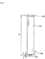
- the piezoelectric actuator 100 includes piezoelectric elements (not illustrated) stacked on the case main body 101 having a cylindrical shape and illustrated in Fig. 3 .
- the case main body 101 is made of a metal such as stainless alloy, and is closed on an end surface on a tip portion 102 side having a hemispherical shape, and on an end surface on a base end portion 103 side. Voltage is applied to the stacked piezoelectric elements, causing expansion, thereby elastically deforming the end surface on the tip portion 102 side of the case main body 101, and displacing the tip portion 102 having a hemispherical shape in the longitudinal direction.
- a predetermined voltage V0 in which an expansion of the piezoelectric actuator 100 becomes d is applied in advance, bringing a total length of the piezoelectric actuator 100 to L0. Then, when a voltage higher than the predetermined voltage V0 is applied, the total length of the piezoelectric actuator 100 becomes L0+d at a maximum and, when a voltage lower than the predetermined voltage V0 (including no voltage) is applied, the total length of the piezoelectric actuator 100 becomes L0-d at a minimum. Accordingly, the total length from the tip portion 102 to the base end portion 103 can be expanded and contracted in the opening and closing directions A1, A2. Note that, while the tip portion 102 of the piezoelectric actuator 100 has a hemispherical shape in this embodiment, the shape is not necessarily limited thereto, and the tip portion may be a flat surface.
- electric power is supplied to the piezoelectric actuator 100 by a wiring 105.
- the wiring 105 is led to the pipe 160 through a flow channel 71 of the adjustment body 70 and the pipe joint 150, and is drawn outside from the middle of the pipe 160.
- the position of the base end portion 103 in the opening and closing directions of the piezoelectric actuator 100 is regulated by a lower end surface of the adjustment body 70 via the actuator presser 80.
- a thread part provided in an outer peripheral surface of the adjustment body 70 is screwed into a screw hole 56 formed in an upper portion of the casing 50, and the position of the adjustment body 70 in the opening and closing directions A1, A2 is adjusted, making it possible to adjust the position of the piezoelectric actuator 100 in the opening and closing directions A1, A2.
- the tip portion 102 of the piezoelectric actuator 100 comes into contact with a receiving surface 110a having a conical surface shape and formed on an upper surface of the actuator receiver 110 having a disc shape, as illustrated in Fig. 2 .
- the actuator receiver 110 is moveable in the opening and closing directions A1, A2.
- the disc spring 120 serving as an elastic member is provided between a lower surface of the actuator receiver 110 and an upper surface of the closing part 48 of the operation member 40.
- the disc spring 120 is already compressed and elastically deformed to a certain degree and, by a restoring force of this disc spring 120, the actuator receiver 110 is continually pressed in the opening direction A1.
- the piezoelectric actuator 100 is also continually pressed in the opening direction A1, and an upper surface of the base end portion 103 is pressed by the actuator presser 80.
- the piezoelectric actuator 100 is disposed in a predetermined position with respect to the valve body 10.
- the piezoelectric actuator 100 is not coupled to any member, and thus is relatively moveable in the opening and closing directions A1, A2, with respect to the operation member 40.
- the number and orientation of the disc springs 120 can be changed as appropriate in accordance with conditions. Further, while an elastic member other than the disc spring 120, such as a coil spring or a leaf spring, can be used, use of the disc spring offers advantages of easy adjustment of spring rigidity, stroke, and the like.
- a gap is formed between a regulating surface 110t on the lower surface side of the actuator receiver 110, and a contact surface 40t on the upper surface side of the closing part 48 of the operation member 40.
- a distance of this gap corresponds to a lift amount Lf of the diaphragm 20.
- the lift amount Lf regulates the aperture of the valve, that is, the flow rate.
- the lift amount Lf can be changed by adjusting the position of the adjustment body 70 described above in the opening and closing directions A1, A2.
- the operation member 40 in the state illustrated in Fig. 2 is positioned in a closed position CP on the basis of the contact surface 40t. When this contact surface 40t moves to a position in contact with the regulating surface 110t of the actuator receiver 110, that is, an open position OP, the diaphragm 20 separates from the valve seat 15 by the lift amount Lf.
- valve device 1 having the above-described configuration will be described with reference to Fig. 4 to Fig. 6B .
- the operation member 40 moves further in the opening direction A1 while compressing the disc spring 120, the contact surface 40t of the operation member 40 comes into contact with the regulating surface 11 0t of the actuator receiver 110, and the actuator receiver 110 receives a force in the opening direction A1 from the operation member 40. While this force passes through the tip portion 102 of the piezoelectric actuator 100 and acts as a force that compresses the piezoelectric actuator 100 in the opening and closing directions A1, A2, the piezoelectric actuator 100 has sufficient rigidity against this force. Accordingly, the force in the opening direction A1 acting on the operation member 40 is received at the tip portion 102 of the piezoelectric actuator 100, and the movement of the operation member 40 in the A1 direction is regulated in the open position OP. In this state, the diaphragm 20 separates from the valve seat 15 by the lift amount Lf described above.
- the piezoelectric actuator 100 is activated.
- a center line Ct indicates the state illustrated in Fig. 5
- the right side of the center line Ct indicates the state after the position of the operation member 40 in the opening and closing directions A1, A2 is adjusted.
- a lift amount Lf- after adjustment which is a distance between the diaphragm 20 and the valve seat 15, is less than the lift amount Lf before adjustment.
- a lift amount Lf+ after adjustment which is the distance between the diaphragm 20 and the valve seat 15, is greater than the lift amount Lf before adjustment.
- the maximum value of the lift amount of the diaphragm 20 is about 100 to 200 ⁇ m, and the adjustment amount by the piezoelectric actuator 100 is about ⁇ 20 ⁇ m.
- Fig. 7 shows a modification of the above-described embodiment.
- a lock nut 180 is provided on an adjustment body 70A, the lock nut 180 is screwed into the screw hole 56, and an upper surface of the adjustment body 70A is pressed by a lower surface of the lock nut 180, inhibiting the revolving of the adjustment body 70A. Defects such as shifting of the open position OP of the operation member 40 and twisting of the wiring 105 caused by rotation of the adjustment body 70A can be prevented.
- valve device 1 described above will be described with reference to Fig. 8 .
- a semiconductor manufacturing system 1000 illustrated in Fig. 8 is a system for executing a semiconductor manufacturing process by ALD method, with 300 denoting a process gas supply source, 400 denoting a gas box, 500 denoting a tank, 600 denoting a control unit, 700 denoting a processing chamber, and 800 denoting an exhaust pump.
- the flow rate of the process gas needs to be precisely adjusted and a certain amount of flow rate needs to be secured by increasing a size of a diameter of the substrate.
- the gas box 400 is an integrated gas system (a fluid control system) in which various fluid control devices, such as a switch valve, a regulator, and a mass flow controller, are integrated and housed in a box to supply an accurately measured process gas to the processing chamber 700.
- various fluid control devices such as a switch valve, a regulator, and a mass flow controller
- the tank 500 functions as a buffer for temporarily storing the process gas supplied from the gas box 400.
- the control unit 600 controls the supply of the operation gas G to the valve device 1, and the flow adjustment by the piezoelectric actuator 100.
- the processing chamber 700 provides a sealed treatment space for forming a film on the substrate by the ALD method.
- the exhaust pump 800 draws a vacuum inside the processing chamber 700.
- initial adjustment of the process gas is possible when an instruction for flow adjustment is sent from the control unit 600 to the valve device 1.
- valve device 1 is used in a semiconductor manufacturing process based on the ALD method is illustrated in the above-described application example, the present invention is not necessarily limited thereto, and can be applied to various targets that require precise flow adjustment, such as an atomic layer etching (ALE) method, for example.
- ALE atomic layer etching
- a piston built into a cylinder chamber activated by gas pressure is used as the main actuator in the above-described embodiment, the present invention is not necessarily limited thereto, and optimal actuators can be variously selected in accordance with the control target.
- piezoelectric actuator is used as the adjusting actuator in the above-described embodiment
- the present invention is not necessarily limited thereto, and various actuators can be adopted, including a mechanism such as a motor such as a stepping motor, a ball screw that coverts rotational movement to linear movement, and a nut; a solenoid coil; and a thermo-actuator that expands and retracts by temperature changes, or the like.
- the piezoelectric actuator 100 is preferably used as the adjusting actuator of the invention of the present application from the viewpoint that the piezoelectric actuator 100 has minimal heat emission, has heat resistance of a hundred and several dozen degrees Celsius, can be activated not only during initial adjustment, but also continually during fluid control, has minimal nonlinear characteristics, such as backlash during expansion and contraction and thus an extremely high positioning accuracy, and can support a relatively large compressive load.
- the piezoelectric actuator 100 can be minimized to the extent possible (the piezoelectric actuator can be miniaturized) and high-precision fine adjustment and high-precision position control of the position of the operation member 40 are made possible by making the piezoelectric actuator 100 perform subsequent high-precision control of the position of the operation member 40.
- the present invention is not necessarily limited thereto and can be applied to a normally open type valve as well.
- the degree of opening of the valve element may be adjusted by using the adjusting actuator.
- the present invention is not necessarily limited thereto, and a configuration in which the positioning of the open position OP of the operation member 40 is executed mechanically, and only the position adjustment of the operation member 40 in the opening and closing directions is executed by the adjusting actuator without supporting the force that acts on the operation member 40, is possible.
- valve element in the above-described embodiment, the present invention is not necessarily limited thereto, and other types of valve elements can also be adopted.
- valve device 1 is disposed outside the gas box 400 serving as a fluid control system
- valve device 1 of the above-described embodiment can also be included in a fluid control system in which various fluid devices, such as a switch valve, a regulator, and a mass flow controller, are integrated and housed in a box.
Landscapes
- Engineering & Computer Science (AREA)
- General Engineering & Computer Science (AREA)
- Mechanical Engineering (AREA)
- Physics & Mathematics (AREA)
- Fluid Mechanics (AREA)
- Electrically Driven Valve-Operating Means (AREA)
- Chemical Vapour Deposition (AREA)
- Fluid-Driven Valves (AREA)
- Automation & Control Theory (AREA)
- Lift Valve (AREA)
Abstract
Description
- The present invention relates to a valve device, a flow control method using this valve device, and a semiconductor manufacturing method.
- In a semiconductor manufacturing process, a fluid control system called an integrated gas system in which various fluid control devices, such as a switch valve, a regulator, and a mass flow controller, are integrated is used to supply an accurately measured process gas to a processing chamber. A box that houses this integrated gas system is called a gas box.
- While normally a process gas output from the gas box described above is directly supplied to the processing chamber, in a treatment process that deposits a film on a substrate by atomic layer deposition (ALD), in order to supply a process gas in a stable manner, the process gas supplied from the gas box is temporarily stored in the tank as a buffer, and a valve provided close to the processing chamber is opened and closed at high frequency, supplying the process gas from the tank to the processing chamber in a vacuum atmosphere. Note that, for examples of the valve provided close to the processing chamber, refer to Patent Documents 1 and 2.
- The ALD is one type of chemical vapor deposition, and a method in which, under film depositing conditions such as temperature and time, two or more types of process gases are allowed to alternately flow on the substrate surface, one type at a time, and caused to react with atoms on the substrate surface, resulting in the deposition of films, one layer at a time. This method allows control per atom layer, making it possible to form a uniform film thickness and grow the film very finely, even in terms of film quality.
- In the semiconductor manufacturing process based on the ALD method, the flow rate of the process gas needs to be precisely adjusted and a certain amount of flow rate needs to be secured by increasing a size of a diameter of the substrate or the like.
-
- Patent Document 1: Japanese Laid-Open Patent Application No.
2007-64333 - Patent Document 2: Japanese Laid-Open Patent Application No.
2016-121776 - Nevertheless, in an air driven valve, it is not easy to precisely adjust the flow rate by pneumatic adjustment or mechanical adjustment. Further, in a semiconductor manufacturing process based on ALD method, the area around the processing chamber becomes high in temperature, and thus the valve is readily affected by temperature. Furthermore, the valve is opened and closed at high frequency, and thus the valve readily ages and changes over time, requiring significant man-hours for the flow adjustment task.
- An object of the present invention is to provide a valve device capable of precisely adjusting a flow rate of a fluid while securing the flow rate.
- Another object of the present invention is to provide a valve device capable of greatly reducing flow adjustment man-hours.
- Yet another object of the present invention is to provide a valve device capable of immediately executing flow adjustment.
- Yet another object of the present invention is to provide a flow control method that uses the valve device described above, a flow control system, a semiconductor manufacturing system, and a semiconductor manufacturing method.
- A valve device according to the present invention comprises:
- a valve body that defines a flow path;
- a valve element capable of opening and closing a flow path of the valve body;
- an operation member that operates the valve element and is moveably provided between a closed position where the valve element closes the flow path and an open position where the valve element opens the flow path, set in advance, in opening and closing directions that allow the valve element to open and close the flow path;
- a main actuator that moves the operation member to the open position or the closed position; and
- an adjusting actuator for adjusting a position of the operation member positioned in the open position.
- Preferably, a configuration can be adopted in which the main actuator moves the operation member to the open position, and the adjusting actuator adjusts the position of the operation member, that has been positioned in the open position by the main actuator, in the opening and closing directions.
- More preferably, a configuration can be adopted in which the adjusting actuator is disposed in a predetermined position with respect to the valve body, and adjusts the position of the operation member, that has reached the target position, in the opening and closing direction while receiving a force acting on the operation member, at a tip portion of the adjusting actuator to regulate the movement of the operation member.
- More preferably, a configuration can be adopted in which the adjusting actuator adjusts the position of the operation member in the opening and closing directions by expansion and contraction of a total length from the tip portion to a base end portion in the opening and closing directions. A configuration can be adopted in which the adjusting actuator includes an actuator that utilizes expansion and contraction of the piezoelectric element, more preferably comprises a case provided with a base end portion and a tip portion in the opening and closing directions, and a piezoelectric element housed in the case and stacked between the base end portion and the tip portion, and expands and contracts a total length between the base end portion and the tip portion of the case using expansion and contraction of the piezoelectric element.
- A flow control method of the present invention controls a flow rate of a fluid using the above-described valve device, and operates an adjusting actuator while securing the flow rate by a stroke of a main actuator, making precise flow control possible.
- A semiconductor manufacturing method of the present invention comprises a step of using the valve device described above for flow control of a process gas in a manufacturing process of a semiconductor device that requires a treatment process by the process gas in a sealed chamber.
- A fluid control system of the present invention is a fluid control system comprising:
a plurality of fluid devices, wherein:
the fluid devices include the valve device having the above-described configuration. - A semiconductor manufacturing system of the present invention includes the valve device having the above-described configuration for control of a process gas in a manufacturing process of a semiconductor device that requires a treatment process by the process gas in a sealed chamber.
- According to the present invention, a valve device comprises an adjustment actuator in addition to a main actuator, making precise flow adjustment possible and greatly reducing flow adjustment man-hours.
- According to the present invention, the main actuator and the adjustment actuator are selected as appropriate, making a required degree of opening of valve achievable and precise flow control possible.
- According to the present invention, flow adjustment and flow control are possible when an instruction is provided to the adjustment actuator, making it possible to immediately adjust and, in real-time, control the flow rate using the adjusting actuator.
-
-
Fig. 1 is a longitudinal sectional view of a valve device according to an embodiment of the present invention. -
Fig. 2 is an enlarged sectional view of a main part of the valve device inFig. 1 , in a closed state. -
Fig. 3 is an explanatory drawing illustrating an operation of a piezoelectric actuator. -
Fig. 4 is a longitudinal sectional view of the valve device inFig. 1 , in an open state. -
Fig. 5 is an enlarged sectional view of a main part of the valve device inFig. 4 . -
Fig. 6A is an enlarged sectional view of a main part for explaining a state during flow adjustment (during flow decrease) of the valve device inFig. 4 . -
Fig. 6B is an enlarged sectional view of a main part for explaining a state during flow adjustment (during flow increase) of the valve device inFig. 4 . -
Fig. 7 is a longitudinal sectional view illustrating a modification of the valve device according to an embodiment of the present invention. -
Fig. 8 is a schematic drawing illustrating an application example of the valve device according to an embodiment of the present invention to a semiconductor manufacturing process. - Embodiments of the present invention are described below with reference to the drawings. Note that, in this specification and the drawings, components having substantially the same function are denoted using the same reference numeral, and duplicate descriptions thereof are omitted.
-
Fig. 1 is a drawing illustrating a configuration of a valve device according to an embodiment of the present invention, and shows the state when the valve is fully closed,Fig. 2 is an enlarged sectional view of main parts inFig. 1 , andFig. 3 is a drawing for explaining an operation of a piezoelectric actuator as an adjusting actuator. It should be noted that, in the explanations below, an upward direction is denoted as an opening direction A1, and a downward direction is denoted as a closing direction A2. - In
Fig. 1, 1 denotes a valve device, 10 denotes a valve body, 20 denotes a diaphragm as a valve element, 38 denotes a diaphragm presser, 30 denotes a bonnet, 40 denotes an operation member, 50 denotes casing, 60 denotes a main actuator, 70 denotes an adjustment body, 80 denotes an actuator presser, 90 denotes a coil spring, 100 denotes a piezoelectric actuator as an adjusting actuator, 110 denotes an actuator receiver, 120 denotes a disc spring as an elastic member, and OR denotes an O-ring as a seal member. - The
valve body 10 is formed of stainless steel, comprises a valve bodymain unit 10a having a block shape, and connectingparts main unit 10a, and definesflow paths flow paths parts valve chamber 14 having a recessed shape opening upward. On a bottom surface of thevalve chamber 14, avalve seat 15 made of a synthetic resin (such as perfluoroalkoxy alkane (PFA), polyamide (PA), polyimide (PI), or polychlorotrifluoroethylene (PCTFE)) is fitted and fixed to a mounting groove provided to an opening peripheral edge on the other end side of theflow path 12. Note that, in this embodiment, as is clear inFig. 2 , thevalve seat 15 is fixed in the mounting groove by swaging. - The
diaphragm 20 is a valve element provided so as to be capable of opening and closing theflow paths valve body 10, is arranged above thevalve seat 15, holds an airtightness of thevalve chamber 14, and opens and closes theflow paths valve seat 15. In this embodiment, thediaphragm 20, formed by swelling center portions of a thin plate made of a metal such as special stainless steel, and a nickel and cobalt alloy thin plate upward, has a spherical shell shape in which an upwardly convex arc shape is the natural state. Thediaphragm 20 is configured by laminating three special stainless steel thin plates, and one nickel and cobalt alloy thin plate. - The
diaphragm 20 is mounted on a protruding portion of an inner peripheral surface of thevalve chamber 14 at the peripheral edge portion thereof, and by screwing a lower end portion of thebonnet 30 inserted into thevalve chamber 14 into athread part 16 of thevalve body 10, thediaphragm 20 is pressed to the protruding portion side of thevalve body 10 via apressing adapter 25 made of a stainless alloy, and fixed in an airtight state. Note that the nickel and cobalt alloy thin film is disposed on a contact gas side. - It should be noted that a diaphragm having another configuration can also be used.
- The
operation member 40 is a member for operating thediaphragm 20 so as to make thediaphragm 20 open and close theflow paths part 48, and open on an upper end side. Theoperation member 40 is fitted to an inner peripheral surface of thebonnet 30 and an inner peripheral surface of atubular part 51 formed in thecasing 50, and is moveably supported in an up-down direction. Note that A1, A2 indicated inFig. 1 andFig. 2 are opening and closing directions of theoperation member 40, A1 denotes the opening direction and A2 denotes the closing direction. While, in this embodiment, the upward direction and the downward direction with respect to thevalve body 10 are the opening direction A1 and the closing direction A2, respectively, the present invention is not necessarily limited thereto. - The
diaphragm presser 38 that is made of a synthetic resin such as polyimide and comes into contact with a center upper surface of thediaphragm 20, is mounted on the lower end surface of theoperation member 40. - The
coil spring 90 is provided between an upper surface of aflange part 45 formed on an outer peripheral surface of theoperation member 40 and a ceiling surface of the casing, and theoperation member 40 is continually pressed in the closing direction A2 by thecoil spring 90. Thus, as illustrated inFig. 2 , with themain actuator 60 not activated, thediaphragm 20 is pressed against thevalve seat 15, and the area between theflow paths - Note that the
flange part 45 may be integrated with or separated from theoperation member 40. - The
coil spring 90 is housed in a holdingpart 52 formed between an inner peripheral surface of thecasing 50 and thetubular part 51. While thecoil spring 90 is used in this embodiment, the present invention is not necessarily limited thereto, and other types of springs can be used, such as a disc spring or a leaf spring. - The
casing 50 is fixed to thebonnet 30 by screwing a lower end inner periphery thereof into athread part 36 formed in an upper end outer periphery of thebonnet 30. Note that abulkhead 63 having an annular shape is fixed between an upper end surface of thebonnet 30 and thecasing 50. - Cylinder chambers C1, C2 vertically divided by the
bulkhead 63 are formed between the outer peripheral surface of theoperation member 40, and thecasing 50 and thebonnet 30. - A
piston 61 formed into an annular shape is fitted and inserted into the cylinder chamber C1 on an upper side, and apiston 62 formed into an annular shape is fitted and inserted into the cylinder chamber C2 on a lower side. These cylinder chambers C1, C2 andpistons main actuator 60 in which theoperation member 40 is moved in the opening direction A1. Themain actuator 60 increases the area on which pressure acts by using the twopistons - A space on the upper side of the
piston 61 of the cylinder chamber C1 communicates with the atmosphere by aventilation path 53. A space on the upper side of thepiston 62 of the cylinder chamber C2 communicates with the atmosphere by a ventilation path h1. - The spaces on the lower sides of the
pistons flow channels operation member 40. Theflow channels operation member 40 and an outer peripheral surface of a casemain body 101 of thepiezoelectric actuator 100, and this flow channel Ch communicates with a space SP formed by an upper end surface of theoperation member 40 and thetubular part 51 of thecasing 50 and a lower end surface of theadjustment body 70. Then, aflow channel 81 formed in theactuator presser 80 having an annular shape connects the space SP and aflow channel 71 that passes through a central portion of theadjustment body 70. Theflow channel 71 of theadjustment body 70 communicates with apipe 160 via apipe joint 150. - The
piezoelectric actuator 100 includes piezoelectric elements (not illustrated) stacked on the casemain body 101 having a cylindrical shape and illustrated inFig. 3 . The casemain body 101 is made of a metal such as stainless alloy, and is closed on an end surface on atip portion 102 side having a hemispherical shape, and on an end surface on abase end portion 103 side. Voltage is applied to the stacked piezoelectric elements, causing expansion, thereby elastically deforming the end surface on thetip portion 102 side of the casemain body 101, and displacing thetip portion 102 having a hemispherical shape in the longitudinal direction. Given 2d as a maximum stroke of the stacked piezoelectric elements, a predetermined voltage V0 in which an expansion of thepiezoelectric actuator 100 becomes d is applied in advance, bringing a total length of thepiezoelectric actuator 100 to L0. Then, when a voltage higher than the predetermined voltage V0 is applied, the total length of thepiezoelectric actuator 100 becomes L0+d at a maximum and, when a voltage lower than the predetermined voltage V0 (including no voltage) is applied, the total length of thepiezoelectric actuator 100 becomes L0-d at a minimum. Accordingly, the total length from thetip portion 102 to thebase end portion 103 can be expanded and contracted in the opening and closing directions A1, A2. Note that, while thetip portion 102 of thepiezoelectric actuator 100 has a hemispherical shape in this embodiment, the shape is not necessarily limited thereto, and the tip portion may be a flat surface. - As illustrated in
Fig. 1 , electric power is supplied to thepiezoelectric actuator 100 by awiring 105. Thewiring 105 is led to thepipe 160 through aflow channel 71 of theadjustment body 70 and the pipe joint 150, and is drawn outside from the middle of thepipe 160. - The position of the
base end portion 103 in the opening and closing directions of thepiezoelectric actuator 100 is regulated by a lower end surface of theadjustment body 70 via theactuator presser 80. In theadjustment body 70, a thread part provided in an outer peripheral surface of theadjustment body 70 is screwed into ascrew hole 56 formed in an upper portion of thecasing 50, and the position of theadjustment body 70 in the opening and closing directions A1, A2 is adjusted, making it possible to adjust the position of thepiezoelectric actuator 100 in the opening and closing directions A1, A2. - The
tip portion 102 of thepiezoelectric actuator 100 comes into contact with a receivingsurface 110a having a conical surface shape and formed on an upper surface of theactuator receiver 110 having a disc shape, as illustrated inFig. 2 . Theactuator receiver 110 is moveable in the opening and closing directions A1, A2. - The
disc spring 120 serving as an elastic member is provided between a lower surface of theactuator receiver 110 and an upper surface of the closingpart 48 of theoperation member 40. In the state illustrated inFig. 2 , thedisc spring 120 is already compressed and elastically deformed to a certain degree and, by a restoring force of thisdisc spring 120, theactuator receiver 110 is continually pressed in the opening direction A1. Accordingly, thepiezoelectric actuator 100 is also continually pressed in the opening direction A1, and an upper surface of thebase end portion 103 is pressed by theactuator presser 80. As a result, thepiezoelectric actuator 100 is disposed in a predetermined position with respect to thevalve body 10. Thepiezoelectric actuator 100 is not coupled to any member, and thus is relatively moveable in the opening and closing directions A1, A2, with respect to theoperation member 40. - The number and orientation of the disc springs 120 can be changed as appropriate in accordance with conditions. Further, while an elastic member other than the
disc spring 120, such as a coil spring or a leaf spring, can be used, use of the disc spring offers advantages of easy adjustment of spring rigidity, stroke, and the like. - As illustrated in
Fig. 2 , with thediaphragm 20 being in contact with thevalve seat 15 and the valve being closed, a gap is formed between a regulatingsurface 110t on the lower surface side of theactuator receiver 110, and acontact surface 40t on the upper surface side of the closingpart 48 of theoperation member 40. A distance of this gap corresponds to a lift amount Lf of thediaphragm 20. The lift amount Lf regulates the aperture of the valve, that is, the flow rate. The lift amount Lf can be changed by adjusting the position of theadjustment body 70 described above in the opening and closing directions A1, A2. Theoperation member 40 in the state illustrated inFig. 2 is positioned in a closed position CP on the basis of thecontact surface 40t. When thiscontact surface 40t moves to a position in contact with the regulatingsurface 110t of theactuator receiver 110, that is, an open position OP, thediaphragm 20 separates from thevalve seat 15 by the lift amount Lf. - Next, the operation of the valve device 1 having the above-described configuration will be described with reference to
Fig. 4 to Fig. 6B . - As illustrated in
Fig. 4 , when an operation gas G having a predetermined pressure is supplied into the valve device 1 through thepipe 160, a thrust pressing up thepistons operation member 40 in the opening direction A1 acts. The pressure of the operation gas G is set to a sufficient value that allows theoperation member 40 to move in the opening direction A1 against the pressing force in the closing direction A2 acting from thecoil spring 90 and thedisc spring 120 to theoperation member 40. When such an operation gas G is supplied, as illustrated inFig. 5 , theoperation member 40 moves further in the opening direction A1 while compressing thedisc spring 120, thecontact surface 40t of theoperation member 40 comes into contact with the regulating surface 11 0t of theactuator receiver 110, and theactuator receiver 110 receives a force in the opening direction A1 from theoperation member 40. While this force passes through thetip portion 102 of thepiezoelectric actuator 100 and acts as a force that compresses thepiezoelectric actuator 100 in the opening and closing directions A1, A2, thepiezoelectric actuator 100 has sufficient rigidity against this force. Accordingly, the force in the opening direction A1 acting on theoperation member 40 is received at thetip portion 102 of thepiezoelectric actuator 100, and the movement of theoperation member 40 in the A1 direction is regulated in the open position OP. In this state, thediaphragm 20 separates from thevalve seat 15 by the lift amount Lf described above. - When the flow rate of the fluid output and supplied from the
flow path 13 of the valve device 1 in the state illustrated inFig. 5 is adjusted, thepiezoelectric actuator 100 is activated. - In
Fig. 6A andFig. 6B , the left side of a center line Ct indicates the state illustrated inFig. 5 , and the right side of the center line Ct indicates the state after the position of theoperation member 40 in the opening and closing directions A1, A2 is adjusted. - When adjustment is made in the direction that decreases the flow rate of the fluid, the
piezoelectric actuator 100 is expanded and theoperation member 40 is moved in the closing direction A2, as illustrated inFig. 6A . Accordingly, a lift amount Lf- after adjustment, which is a distance between thediaphragm 20 and thevalve seat 15, is less than the lift amount Lf before adjustment. - When adjustment is made in the direction that increases the flow rate of the fluid, the
piezoelectric actuator 100 is contracted and theoperation member 40 is moved in the opening direction A1, as illustrated inFig. 6B . As a result, a lift amount Lf+ after adjustment, which is the distance between thediaphragm 20 and thevalve seat 15, is greater than the lift amount Lf before adjustment. - In this embodiment, the maximum value of the lift amount of the
diaphragm 20 is about 100 to 200 µm, and the adjustment amount by thepiezoelectric actuator 100 is about ±20 µm. - That is, while the lift amount of the
diaphragm 20 cannot be covered according to the stroke of thepiezoelectric actuator 100, by using both themain actuator 60 and thepiezoelectric actuator 100 operated by the operation gas G, it is possible to precisely adjust the flow rate using thepiezoelectric actuator 100 having a relatively short stroke while securing the flow rate supplied by the valve device 1 using themain actuator 60 having a relatively long stroke, thereby eliminating the need to manually adjust the flow rate using theadjustment body 70 or the like, and thus significantly reduce flow adjustment man-hours. - According to this embodiment, precise flow adjustment is possible by simply changing the voltage applied to the
piezoelectric actuator 100, making it possible to immediately adjust and, in real-time, control the flow rate. - Next,
Fig. 7 shows a modification of the above-described embodiment. - While the
adjustment body 70 is simply screwed into thescrew hole 56 of thecasing 50 in the above-described embodiment, inFig. 7 , alock nut 180 is provided on anadjustment body 70A, thelock nut 180 is screwed into thescrew hole 56, and an upper surface of theadjustment body 70A is pressed by a lower surface of thelock nut 180, inhibiting the revolving of theadjustment body 70A. Defects such as shifting of the open position OP of theoperation member 40 and twisting of thewiring 105 caused by rotation of theadjustment body 70A can be prevented. - Next, an application example of the valve device 1 described above will be described with reference to
Fig. 8 . - A
semiconductor manufacturing system 1000 illustrated inFig. 8 is a system for executing a semiconductor manufacturing process by ALD method, with 300 denoting a process gas supply source, 400 denoting a gas box, 500 denoting a tank, 600 denoting a control unit, 700 denoting a processing chamber, and 800 denoting an exhaust pump. - In the semiconductor manufacturing process based on the ALD method, the flow rate of the process gas needs to be precisely adjusted and a certain amount of flow rate needs to be secured by increasing a size of a diameter of the substrate.
- The
gas box 400 is an integrated gas system (a fluid control system) in which various fluid control devices, such as a switch valve, a regulator, and a mass flow controller, are integrated and housed in a box to supply an accurately measured process gas to theprocessing chamber 700. - The
tank 500 functions as a buffer for temporarily storing the process gas supplied from thegas box 400. - The
control unit 600 controls the supply of the operation gas G to the valve device 1, and the flow adjustment by thepiezoelectric actuator 100. - The
processing chamber 700 provides a sealed treatment space for forming a film on the substrate by the ALD method. - The
exhaust pump 800 draws a vacuum inside theprocessing chamber 700. - According to such a system configuration as described above, initial adjustment of the process gas is possible when an instruction for flow adjustment is sent from the
control unit 600 to the valve device 1. - Further, even when a film formation process is being executed in the
processing chamber 700, flow adjustment of the process gas is possible, allowing optimization of the process gas flow rate in real-time. - While a case where the valve device 1 is used in a semiconductor manufacturing process based on the ALD method is illustrated in the above-described application example, the present invention is not necessarily limited thereto, and can be applied to various targets that require precise flow adjustment, such as an atomic layer etching (ALE) method, for example.
- While a piston built into a cylinder chamber activated by gas pressure is used as the main actuator in the above-described embodiment, the present invention is not necessarily limited thereto, and optimal actuators can be variously selected in accordance with the control target.
- While a piezoelectric actuator is used as the adjusting actuator in the above-described embodiment, the present invention is not necessarily limited thereto, and various actuators can be adopted, including a mechanism such as a motor such as a stepping motor, a ball screw that coverts rotational movement to linear movement, and a nut; a solenoid coil; and a thermo-actuator that expands and retracts by temperature changes, or the like. Note that the
piezoelectric actuator 100 is preferably used as the adjusting actuator of the invention of the present application from the viewpoint that thepiezoelectric actuator 100 has minimal heat emission, has heat resistance of a hundred and several dozen degrees Celsius, can be activated not only during initial adjustment, but also continually during fluid control, has minimal nonlinear characteristics, such as backlash during expansion and contraction and thus an extremely high positioning accuracy, and can support a relatively large compressive load. Further, when the open position OP of theoperation member 40 is precisely mechanically adjusted in advance by theadjustment body 70, a maximum stroke of thepiezoelectric actuator 100 can be minimized to the extent possible (the piezoelectric actuator can be miniaturized) and high-precision fine adjustment and high-precision position control of the position of theoperation member 40 are made possible by making thepiezoelectric actuator 100 perform subsequent high-precision control of the position of theoperation member 40. - While a so-called normally closed type valve is given as an example in the above-described embodiment, the present invention is not necessarily limited thereto and can be applied to a normally open type valve as well. In this case, for example, the degree of opening of the valve element may be adjusted by using the adjusting actuator.
- While, in the configuration of the above-described embodiment, a force that acts on the
operation member 40 is supported (received) by thepiezoelectric actuator 100, the present invention is not necessarily limited thereto, and a configuration in which the positioning of the open position OP of theoperation member 40 is executed mechanically, and only the position adjustment of theoperation member 40 in the opening and closing directions is executed by the adjusting actuator without supporting the force that acts on theoperation member 40, is possible. - While the diaphragm is illustrated as the valve element in the above-described embodiment, the present invention is not necessarily limited thereto, and other types of valve elements can also be adopted.
- While, in the configuration of the above-described embodiment, the valve device 1 is disposed outside the
gas box 400 serving as a fluid control system, the valve device 1 of the above-described embodiment can also be included in a fluid control system in which various fluid devices, such as a switch valve, a regulator, and a mass flow controller, are integrated and housed in a box. -
- 1
- Valve device
- 10
- Valve body
- 15
- Valve seat
- 20
- Diaphragm
- 25
- Pressing adapter
- 30
- Bonnet
- 38
- Diaphragm presser
- 40
- Operation member
- 40t
- Contact surface
- 45
- Flange part
- 48
- Closing part
- 50
- Casing
- 60
- Main actuator
- 61, 62
- Piston
- 63
- Bulkhead
- 70, 70A
- Adjustment body
- 71
- Flow channel
- 80
- Actuator presser
- 81
- Flow channel
- 90
- Coil spring
- 100
- Piezoelectric actuator (Adjusting actuator)
- 101
- Case main body
- 102
- Tip portion
- 103
- Base end portion
- 105
- Wiring
- 110
- Actuator receiver
- 110t
- Regulating surface
- 120
- Disc spring (Elastic member)
- 150
- Pipe joint
- 160
- Pipe
- 180
- Lock nut
- 300
- Process gas supply source
- 400
- Gas box
- 500
- Tank
- 600
- Control unit
- 700
- Processing chamber
- 800
- Exhaust pump
- 1000
- Semiconductor manufacturing system
- A1
- Opening direction
- A2
- Closing direction
- C1, C2
- Cylinder chamber
- Ch
- Flow channel
- SP
- Space
- OP
- Open position
- CP
- Closed position
- OR
- O-ring
- G
- Operation gas
- Lf
- Lift amount before adjustment
- Lf+, Lf-
- Lift amount after adjustment
Claims (12)
- A valve device comprising:a valve body that defines a flow path;a valve element capable of opening and closing a flow path of the valve body;an operation member that operates the valve element and is moveably provided between a closed position where the valve element closes the flow path and an open position where the valve element opens the flow path, set in advance, in opening and closing directions that allow the valve element to open and close the flow path;a main actuator that moves the operation member to the open position or the closed position; andan adjusting actuator for adjusting a position of the operation member positioned in the open position.
- The valve device according to claim 1, wherein:the main actuator moves the operation member to the open position; andthe adjusting actuator adjusts the position of the operation member, that has been positioned in the open position by the main actuator, in the opening and closing directions.
- The valve device according to claim 2, wherein
the adjusting actuator is disposed in a predetermined position with respect to the valve body, and adjusts the position of the operation member, that has reached the open position, in the opening and closing directions while receiving a force acting on the operation member at a tip portion of the adjusting actuator to regulate the movement of the operation member. - The valve device according to claim 3, wherein
the adjusting actuator adjusts the position of the operation member in the opening and closing directions by expansion and contraction of a total length from the tip portion to a base end portion in the opening and closing directions. - The valve device according to claim 3 or 4, further comprising an elastic member that continually presses the adjusting actuator toward the predetermined position, interposed between the operation member and the adjusting actuator.
- The valve device according to any one of claims 1 to 5, wherein
the adjusting actuator is an actuator that utilizes expansion and contraction of the piezoelectric element. - The valve device according to claim 6, wherein
the adjusting actuator comprises a case provided with a base end portion and a tip portion in the opening and closing directions, and a piezoelectric element housed in the case and stacked between the base end portion and the tip portion, and expands and contracts a total length between the base end portion and the tip portion of the case using expansion and contraction of the piezoelectric element. - The valve device according to any one of claims 1 to 7, wherein
the main actuator is an actuator that uses gas pressure as a driving source. - A flow control method for adjusting a flow rate of a fluid using the valve device as defined in claims 1 to 8.
- A fluid control system comprising:
a plurality of fluid devices, wherein:
the fluid devices include the valve device as defined in any one of claims 1 to 8. - A semiconductor manufacturing method comprising a step of using the valve device as defined in any one of claims 1 to 8 for flow control of a process gas in a manufacturing process of a semiconductor device that requires a treatment process by the process gas in a sealed chamber.
- A semiconductor manufacturing system comprising the valve device as defined in any one of claims 1 to 8 for control of a process gas in a manufacturing process of a semiconductor device that requires a treatment process by the process gas in a sealed chamber.
Applications Claiming Priority (2)
| Application Number | Priority Date | Filing Date | Title |
|---|---|---|---|
| JP2016218093 | 2016-11-08 | ||
| PCT/JP2017/039729 WO2018088326A1 (en) | 2016-11-08 | 2017-11-02 | Valve device, flow rate control method using said valve device, and method of manufacturing semiconductor |
Publications (2)
| Publication Number | Publication Date |
|---|---|
| EP3540280A1 true EP3540280A1 (en) | 2019-09-18 |
| EP3540280A4 EP3540280A4 (en) | 2019-11-27 |
Family
ID=62110580
Family Applications (1)
| Application Number | Title | Priority Date | Filing Date |
|---|---|---|---|
| EP17869179.6A Pending EP3540280A4 (en) | 2016-11-08 | 2017-11-02 | VALVE DEVICE, FLOW CONTROL METHOD USING SAID VALVE DEVICE, AND SEMICONDUCTOR MANUFACTURING METHOD |
Country Status (7)
| Country | Link |
|---|---|
| US (1) | US11098819B2 (en) |
| EP (1) | EP3540280A4 (en) |
| JP (2) | JP6336692B1 (en) |
| KR (2) | KR102312480B1 (en) |
| CN (1) | CN109952459B (en) |
| TW (1) | TWI671483B (en) |
| WO (1) | WO2018088326A1 (en) |
Cited By (1)
| Publication number | Priority date | Publication date | Assignee | Title |
|---|---|---|---|---|
| US11035494B2 (en) | 2017-06-22 | 2021-06-15 | Fujikin Incorporated | Flow rate control apparatus and flow rate control method for the flow rate control apparatus |
Families Citing this family (14)
| Publication number | Priority date | Publication date | Assignee | Title |
|---|---|---|---|---|
| CN110023659B (en) * | 2016-11-30 | 2021-01-29 | 株式会社富士金 | Valve device, flow rate control method using the valve device, and semiconductor manufacturing method |
| CN111133239A (en) * | 2017-09-25 | 2020-05-08 | 株式会社富士金 | Valve device, flow rate adjustment method, fluid control device, flow rate control method, semiconductor manufacturing apparatus, and semiconductor manufacturing method |
| US11536386B2 (en) * | 2018-08-30 | 2022-12-27 | Fujikin Incorporated | Fluid control device |
| JP7308506B2 (en) * | 2019-01-31 | 2023-07-14 | 株式会社フジキン | VALVE DEVICE, FLOW CONTROL METHOD USING THIS VALVE DEVICE, SEMICONDUCTOR MANUFACTURING METHOD, AND SEMICONDUCTOR MANUFACTURER |
| CN113423987A (en) * | 2019-01-31 | 2021-09-21 | 株式会社富士金 | Valve device, flow rate control method, fluid control device, semiconductor manufacturing method, and semiconductor manufacturing device |
| KR102542263B1 (en) | 2019-01-31 | 2023-06-13 | 가부시키가이샤 후지킨 | Valve device, flow control method using this valve device, fluid control device, semiconductor manufacturing method, and semiconductor manufacturing device |
| CN110307351A (en) * | 2019-07-10 | 2019-10-08 | 广东工业大学 | A piezoelectric ceramic flow limiting valve |
| US11079035B2 (en) * | 2019-07-12 | 2021-08-03 | Pivotal Systems Corporation | Preloaded piezo actuator and gas valve employing the actuator |
| IL268254B2 (en) * | 2019-07-24 | 2024-10-01 | Ham Let Israel Canada Ltd | Flow control accessory |
| JP7382054B2 (en) * | 2019-08-29 | 2023-11-16 | 株式会社フジキン | Valve devices and flow control devices |
| US11927274B2 (en) | 2019-11-25 | 2024-03-12 | M-System Co., Ltd. | Actuator and fluid control device |
| KR20230131613A (en) | 2022-03-07 | 2023-09-14 | 주식회사 코일넷 | A toilet furnished with decomposing tank using thermophiles |
| DE102022003518A1 (en) * | 2022-09-23 | 2024-03-28 | Vat Holding Ag | PNEUMATIC GAS INLET VALVE WITH ADJUSTABLE STOP |
| JP2024158856A (en) * | 2023-04-28 | 2024-11-08 | 株式会社堀場エステック | FLUID CONTROL VALVE, FLUID CONTROL DEVICE, AND MATERIAL SUPPLY SYSTEM |
Family Cites Families (19)
| Publication number | Priority date | Publication date | Assignee | Title |
|---|---|---|---|---|
| US5092360A (en) | 1989-11-14 | 1992-03-03 | Hitachi Metals, Ltd. | Flow rated control valve using a high-temperature stacked-type displacement device |
| JP3532273B2 (en) * | 1994-12-20 | 2004-05-31 | 株式会社コガネイ | Fluid pressure operated valve device |
| JPH10318385A (en) | 1997-05-21 | 1998-12-04 | Hitachi Metals Ltd | Metallic diaphragm type flow regulating valve |
| JP2001317646A (en) | 2000-05-08 | 2001-11-16 | Smc Corp | Piezoelectric fluid control valve |
| IT1320475B1 (en) | 2000-06-30 | 2003-11-26 | Fiat Ricerche | SELF-COMPENSATED PIEZOELECTRIC ACTUATOR FOR A CONTROL VALVE. |
| AU2003211853A1 (en) * | 2003-03-07 | 2004-09-28 | Ckd Corporation | Flow control valve |
| JP5054904B2 (en) | 2005-08-30 | 2012-10-24 | 株式会社フジキン | Direct touch type metal diaphragm valve |
| KR100812560B1 (en) | 2005-09-07 | 2008-03-13 | 씨케이디 가부시키 가이샤 | Flow control valve |
| JP4743763B2 (en) * | 2006-01-18 | 2011-08-10 | 株式会社フジキン | Piezoelectric element driven metal diaphragm type control valve |
| JP4933936B2 (en) * | 2007-03-30 | 2012-05-16 | 株式会社フジキン | Piezoelectric drive valve |
| JP5082989B2 (en) * | 2008-03-31 | 2012-11-28 | 日立金属株式会社 | Flow control device, verification method thereof, and flow control method |
| US20130000759A1 (en) | 2011-06-30 | 2013-01-03 | Agilent Technologies, Inc. | Microfluidic device and external piezoelectric actuator |
| US8783652B2 (en) * | 2012-03-12 | 2014-07-22 | Mps Corporation | Liquid flow control for film deposition |
| JP5775110B2 (en) * | 2013-03-26 | 2015-09-09 | 株式会社フジキン | Flow control valve for flow control device |
| JP6491878B2 (en) | 2014-12-25 | 2019-03-27 | 株式会社フジキン | Fluid controller |
| EP3268752A1 (en) * | 2015-03-13 | 2018-01-17 | Technoprobe S.p.A | Testing head with vertical probes having an improved sliding movement within respective guide holes and correct holding of the probes within the testing head under different operative conditions |
| US11035494B2 (en) * | 2017-06-22 | 2021-06-15 | Fujikin Incorporated | Flow rate control apparatus and flow rate control method for the flow rate control apparatus |
| CN111133239A (en) * | 2017-09-25 | 2020-05-08 | 株式会社富士金 | Valve device, flow rate adjustment method, fluid control device, flow rate control method, semiconductor manufacturing apparatus, and semiconductor manufacturing method |
| CN111164341A (en) * | 2017-09-25 | 2020-05-15 | 株式会社富士金 | Valve device, adjustment information generation method, flow rate adjustment method, fluid control device, flow rate control method, semiconductor manufacturing apparatus, and semiconductor manufacturing method |
-
2017
- 2017-11-02 KR KR1020217019061A patent/KR102312480B1/en active Active
- 2017-11-02 EP EP17869179.6A patent/EP3540280A4/en active Pending
- 2017-11-02 CN CN201780069196.1A patent/CN109952459B/en not_active Expired - Fee Related
- 2017-11-02 US US16/347,934 patent/US11098819B2/en active Active
- 2017-11-02 WO PCT/JP2017/039729 patent/WO2018088326A1/en not_active Ceased
- 2017-11-02 JP JP2018513389A patent/JP6336692B1/en active Active
- 2017-11-02 KR KR1020197015535A patent/KR20190077477A/en not_active Ceased
- 2017-11-07 TW TW106138368A patent/TWI671483B/en active
-
2018
- 2018-05-02 JP JP2018088543A patent/JP2018132195A/en active Pending
Cited By (1)
| Publication number | Priority date | Publication date | Assignee | Title |
|---|---|---|---|---|
| US11035494B2 (en) | 2017-06-22 | 2021-06-15 | Fujikin Incorporated | Flow rate control apparatus and flow rate control method for the flow rate control apparatus |
Also Published As
| Publication number | Publication date |
|---|---|
| WO2018088326A1 (en) | 2018-05-17 |
| JP2018132195A (en) | 2018-08-23 |
| US20190285176A1 (en) | 2019-09-19 |
| CN109952459B (en) | 2021-02-26 |
| JPWO2018088326A1 (en) | 2018-11-15 |
| EP3540280A4 (en) | 2019-11-27 |
| TWI671483B (en) | 2019-09-11 |
| JP6336692B1 (en) | 2018-06-06 |
| KR102312480B1 (en) | 2021-10-14 |
| US11098819B2 (en) | 2021-08-24 |
| KR20190077477A (en) | 2019-07-03 |
| KR20210079403A (en) | 2021-06-29 |
| CN109952459A (en) | 2019-06-28 |
| TW201825817A (en) | 2018-07-16 |
Similar Documents
| Publication | Publication Date | Title |
|---|---|---|
| US11098819B2 (en) | Valve device, flow control method using the same, and semiconductor manufacturing method | |
| US11022224B2 (en) | Valve device, flow control method using the same, and semiconductor manufacturing method | |
| JP7030359B2 (en) | Valve device | |
| US11512993B2 (en) | Valve device, adjustment information generating method, flow rate adjusting method, fluid control system, flow rate control method, semiconductor manufacturing system and semiconductor manufacturing method | |
| JP7113529B2 (en) | Valve device, flow control method, fluid control device, flow control method, semiconductor manufacturing equipment, and semiconductor manufacturing method | |
| JPWO2019171604A1 (en) | Valve device | |
| CN112534166A (en) | Valve device | |
| US11174949B2 (en) | Actuator and valve device using the same |
Legal Events
| Date | Code | Title | Description |
|---|---|---|---|
| STAA | Information on the status of an ep patent application or granted ep patent |
Free format text: STATUS: THE INTERNATIONAL PUBLICATION HAS BEEN MADE |
|
| PUAI | Public reference made under article 153(3) epc to a published international application that has entered the european phase |
Free format text: ORIGINAL CODE: 0009012 |
|
| STAA | Information on the status of an ep patent application or granted ep patent |
Free format text: STATUS: REQUEST FOR EXAMINATION WAS MADE |
|
| 17P | Request for examination filed |
Effective date: 20190523 |
|
| AK | Designated contracting states |
Kind code of ref document: A1 Designated state(s): AL AT BE BG CH CY CZ DE DK EE ES FI FR GB GR HR HU IE IS IT LI LT LU LV MC MK MT NL NO PL PT RO RS SE SI SK SM TR |
|
| AX | Request for extension of the european patent |
Extension state: BA ME |
|
| A4 | Supplementary search report drawn up and despatched |
Effective date: 20191030 |
|
| RIC1 | Information provided on ipc code assigned before grant |
Ipc: F16K 7/17 20060101ALI20191024BHEP Ipc: F16K 31/122 20060101ALI20191024BHEP Ipc: F16K 31/02 20060101AFI20191024BHEP Ipc: F16K 7/16 20060101ALI20191024BHEP Ipc: F16K 31/00 20060101ALI20191024BHEP |
|
| DAV | Request for validation of the european patent (deleted) | ||
| DAX | Request for extension of the european patent (deleted) | ||
| STAA | Information on the status of an ep patent application or granted ep patent |
Free format text: STATUS: EXAMINATION IS IN PROGRESS |
|
| 17Q | First examination report despatched |
Effective date: 20201103 |
|
| GRAP | Despatch of communication of intention to grant a patent |
Free format text: ORIGINAL CODE: EPIDOSNIGR1 |
|
| STAA | Information on the status of an ep patent application or granted ep patent |
Free format text: STATUS: GRANT OF PATENT IS INTENDED |