EP3540231A1 - Compressor with noise damping - Google Patents
Compressor with noise damping Download PDFInfo
- Publication number
- EP3540231A1 EP3540231A1 EP19165450.8A EP19165450A EP3540231A1 EP 3540231 A1 EP3540231 A1 EP 3540231A1 EP 19165450 A EP19165450 A EP 19165450A EP 3540231 A1 EP3540231 A1 EP 3540231A1
- Authority
- EP
- European Patent Office
- Prior art keywords
- compressor
- noise reducing
- base shell
- fixing member
- fixing
- Prior art date
- Legal status (The legal status is an assumption and is not a legal conclusion. Google has not performed a legal analysis and makes no representation as to the accuracy of the status listed.)
- Granted
Links
Images


Classifications
-
- F—MECHANICAL ENGINEERING; LIGHTING; HEATING; WEAPONS; BLASTING
- F04—POSITIVE - DISPLACEMENT MACHINES FOR LIQUIDS; PUMPS FOR LIQUIDS OR ELASTIC FLUIDS
- F04B—POSITIVE-DISPLACEMENT MACHINES FOR LIQUIDS; PUMPS
- F04B39/00—Component parts, details, or accessories, of pumps or pumping systems specially adapted for elastic fluids, not otherwise provided for in, or of interest apart from, groups F04B25/00 - F04B37/00
- F04B39/0027—Pulsation and noise damping means
-
- F—MECHANICAL ENGINEERING; LIGHTING; HEATING; WEAPONS; BLASTING
- F04—POSITIVE - DISPLACEMENT MACHINES FOR LIQUIDS; PUMPS FOR LIQUIDS OR ELASTIC FLUIDS
- F04C—ROTARY-PISTON, OR OSCILLATING-PISTON, POSITIVE-DISPLACEMENT MACHINES FOR LIQUIDS; ROTARY-PISTON, OR OSCILLATING-PISTON, POSITIVE-DISPLACEMENT PUMPS
- F04C18/00—Rotary-piston pumps specially adapted for elastic fluids
- F04C18/02—Rotary-piston pumps specially adapted for elastic fluids of arcuate-engagement type, i.e. with circular translatory movement of co-operating members, each member having the same number of teeth or tooth-equivalents
- F04C18/0207—Rotary-piston pumps specially adapted for elastic fluids of arcuate-engagement type, i.e. with circular translatory movement of co-operating members, each member having the same number of teeth or tooth-equivalents both members having co-operating elements in spiral form
- F04C18/0215—Rotary-piston pumps specially adapted for elastic fluids of arcuate-engagement type, i.e. with circular translatory movement of co-operating members, each member having the same number of teeth or tooth-equivalents both members having co-operating elements in spiral form where only one member is moving
-
- F—MECHANICAL ENGINEERING; LIGHTING; HEATING; WEAPONS; BLASTING
- F04—POSITIVE - DISPLACEMENT MACHINES FOR LIQUIDS; PUMPS FOR LIQUIDS OR ELASTIC FLUIDS
- F04C—ROTARY-PISTON, OR OSCILLATING-PISTON, POSITIVE-DISPLACEMENT MACHINES FOR LIQUIDS; ROTARY-PISTON, OR OSCILLATING-PISTON, POSITIVE-DISPLACEMENT PUMPS
- F04C18/00—Rotary-piston pumps specially adapted for elastic fluids
- F04C18/30—Rotary-piston pumps specially adapted for elastic fluids having the characteristics covered by two or more of groups F04C18/02, F04C18/08, F04C18/22, F04C18/24, F04C18/48, or having the characteristics covered by one of these groups together with some other type of movement between co-operating members
- F04C18/34—Rotary-piston pumps specially adapted for elastic fluids having the characteristics covered by two or more of groups F04C18/02, F04C18/08, F04C18/22, F04C18/24, F04C18/48, or having the characteristics covered by one of these groups together with some other type of movement between co-operating members having the movement defined in group F04C18/08 or F04C18/22 and relative reciprocation between the co-operating members
- F04C18/356—Rotary-piston pumps specially adapted for elastic fluids having the characteristics covered by two or more of groups F04C18/02, F04C18/08, F04C18/22, F04C18/24, F04C18/48, or having the characteristics covered by one of these groups together with some other type of movement between co-operating members having the movement defined in group F04C18/08 or F04C18/22 and relative reciprocation between the co-operating members with vanes reciprocating with respect to the outer member
-
- F—MECHANICAL ENGINEERING; LIGHTING; HEATING; WEAPONS; BLASTING
- F04—POSITIVE - DISPLACEMENT MACHINES FOR LIQUIDS; PUMPS FOR LIQUIDS OR ELASTIC FLUIDS
- F04C—ROTARY-PISTON, OR OSCILLATING-PISTON, POSITIVE-DISPLACEMENT MACHINES FOR LIQUIDS; ROTARY-PISTON, OR OSCILLATING-PISTON, POSITIVE-DISPLACEMENT PUMPS
- F04C29/00—Component parts, details or accessories of pumps or pumping installations, not provided for in groups F04C18/00 - F04C28/00
- F04C29/0042—Driving elements, brakes, couplings, transmissions specially adapted for pumps
- F04C29/0085—Prime movers
-
- F—MECHANICAL ENGINEERING; LIGHTING; HEATING; WEAPONS; BLASTING
- F04—POSITIVE - DISPLACEMENT MACHINES FOR LIQUIDS; PUMPS FOR LIQUIDS OR ELASTIC FLUIDS
- F04C—ROTARY-PISTON, OR OSCILLATING-PISTON, POSITIVE-DISPLACEMENT MACHINES FOR LIQUIDS; ROTARY-PISTON, OR OSCILLATING-PISTON, POSITIVE-DISPLACEMENT PUMPS
- F04C29/00—Component parts, details or accessories of pumps or pumping installations, not provided for in groups F04C18/00 - F04C28/00
- F04C29/06—Silencing
- F04C29/063—Sound absorbing materials
-
- F—MECHANICAL ENGINEERING; LIGHTING; HEATING; WEAPONS; BLASTING
- F04—POSITIVE - DISPLACEMENT MACHINES FOR LIQUIDS; PUMPS FOR LIQUIDS OR ELASTIC FLUIDS
- F04C—ROTARY-PISTON, OR OSCILLATING-PISTON, POSITIVE-DISPLACEMENT MACHINES FOR LIQUIDS; ROTARY-PISTON, OR OSCILLATING-PISTON, POSITIVE-DISPLACEMENT PUMPS
- F04C29/00—Component parts, details or accessories of pumps or pumping installations, not provided for in groups F04C18/00 - F04C28/00
- F04C29/06—Silencing
- F04C29/068—Silencing the silencing means being arranged inside the pump housing
-
- F—MECHANICAL ENGINEERING; LIGHTING; HEATING; WEAPONS; BLASTING
- F04—POSITIVE - DISPLACEMENT MACHINES FOR LIQUIDS; PUMPS FOR LIQUIDS OR ELASTIC FLUIDS
- F04C—ROTARY-PISTON, OR OSCILLATING-PISTON, POSITIVE-DISPLACEMENT MACHINES FOR LIQUIDS; ROTARY-PISTON, OR OSCILLATING-PISTON, POSITIVE-DISPLACEMENT PUMPS
- F04C2230/00—Manufacture
- F04C2230/20—Manufacture essentially without removing material
-
- F—MECHANICAL ENGINEERING; LIGHTING; HEATING; WEAPONS; BLASTING
- F04—POSITIVE - DISPLACEMENT MACHINES FOR LIQUIDS; PUMPS FOR LIQUIDS OR ELASTIC FLUIDS
- F04C—ROTARY-PISTON, OR OSCILLATING-PISTON, POSITIVE-DISPLACEMENT MACHINES FOR LIQUIDS; ROTARY-PISTON, OR OSCILLATING-PISTON, POSITIVE-DISPLACEMENT PUMPS
- F04C2230/00—Manufacture
- F04C2230/60—Assembly methods
-
- F—MECHANICAL ENGINEERING; LIGHTING; HEATING; WEAPONS; BLASTING
- F04—POSITIVE - DISPLACEMENT MACHINES FOR LIQUIDS; PUMPS FOR LIQUIDS OR ELASTIC FLUIDS
- F04C—ROTARY-PISTON, OR OSCILLATING-PISTON, POSITIVE-DISPLACEMENT MACHINES FOR LIQUIDS; ROTARY-PISTON, OR OSCILLATING-PISTON, POSITIVE-DISPLACEMENT PUMPS
- F04C2240/00—Components
- F04C2240/30—Casings or housings
Definitions
- a compressor and a method for assembling a compressor are disclosed herein.
- compressors may be mechanisms that receive power from power generation devices, such as electric motors or turbines, to compress air, refrigerants, or other working gases, thereby increasing a pressure of the working gas.
- power generation devices such as electric motors or turbines
- Compressors are being widely used in home appliances or industrial machineries, such as refrigerators and air-conditioners.
- Compressors may be largely classified into reciprocating compressors, in which a compression space into and from which a working gas is suctioned and discharged, is defined between a piston and a cylinder to allow the piston to be linearly reciprocated in the cylinder, thereby compressing the working gas; rotary compressors in which a compression space, into and from which a working gas may be suctioned or discharged, is defined between a roller that eccentrically rotates and a cylinder to allow the roller to eccentrically rotate along an inner wall of the cylinder, thereby compressing the working gas; and scroll compressors, in which a compression space into and from which a working gas is suctioned or discharged, is defined between an orbiting scroll and a fixed scroll to compress the working gas while the orbiting scroll rotates along the fixed scroll.
- a linear compressor according to the related art is disclosed in Korean Patent Registration No. 10-1307688 .
- the related art linear compressor may suction and compress a refrigerant while a piston is linearly reciprocated in a sealed compressor casing by a linear motor and then discharge the refrigerant.
- the linear motor may include a permanent magnet disposed between an inner stator and an outer stator.
- the permanent magnet may be linearly reciprocated by an electromagnetic force between the permanent magnet and the inner (or outer) stator.
- refrigerant may be suctioned and compressed while the piston is linearly reciprocated within the cylinder, and then, may be discharged.
- Fig. 1 is a schematic diagram of a refrigerator according to an embodiment.
- a refrigerator 1 may include a plurality of devices to drive a refrigeration cycle.
- the refrigerator may include a compressor 10 to compress a refrigerant, a condenser 20 to condense the refrigerant compressed in the compressor 10, a dryer 30 to remove moisture, foreign substances, or oil from the refrigerant condensed in the condenser 20, an expansion device 40 to decompress the refrigerant passing through the dryer 30, and an evaporator 50 to evaporate the refrigerant decompressed in the expansion device 40.
- the refrigerator 1 may further include a condensation fan 25 to blow air toward the condenser 20, and an evaporation fan 55 to blow air toward the evaporator 50.
- the compressor 10 may be a reciprocating compressor, a rotary compressor, or a scroll compressor, for example. Such a compressor will be described with reference to the drawings in detail.
- the expansion device 40 may include a capillary tube having a relatively small diameter.
- a liquid refrigerant condensed in the condenser 20 may be introduced into the dryer 30.
- a gaseous refrigerant may be partially contained in the liquid refrigerant.
- a filter to filter the liquid refrigerant introduced into the dryer 30 may be provided in the dryer 30.
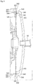
- Fig. 2 is an exploded perspective view of a compressor of the refrigerator of Fig. 1 .
- Fig. 3 is a cross-sectional view of the compressor of FIG. 2 .
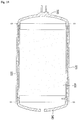
- Fig. 4 is a perspective view of a noise reducing member of the compressor of Fig. 2 .
- Fig. 5 is an exploded perspective view of a noise reducing member according to another embodiment.
- Fig. 6 is a perspective view of a first fixing member of the compressor of Fig. 2 .
- Fig. 7 is a rear view of the first fixing member of Fig. 6 .
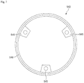
- Fig. 8 is a view illustrating a state in which the noise reducing member is fixed using the first fixing member.
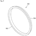
- Fig. 9 is a perspective view of a second fixing member of the compressor of Fig. 2 .
- Fig. 10 is a view illustrating a state in which the noise reducing member is fixed using the second fixing member of Fig. 9 .
- the compressor 10 may be a reciprocating compressor, in which a compression space is defined between a piston and a cylinder to allow a working gas, such as a refrigerant, to be suctioned into and discharged from the compression space to compress the working gas while the piston is linearly reciprocated within the cylinder, that is, a linear compressor.
- the linear compressor 10 may include a suction inlet 100, a discharge outlet 200, a compressor casing 300, a compressor body 400, a noise reducing member 520, a first fixing member 540, and a second fixing member 560.
- the suction inlet 100 may introduce the refrigerant into the compressor body 400 and may pass through a first cover 340 of the compressor casing 300, which will be described hereinbelow.
- the discharge outlet 200 may discharge the compressed refrigerant from the compressor body 400 and may pass through a second cover 360 of the compressor casing 300, which will be described hereinbelow.
- the compressor casing 300 may accommodate the compressor body 400 and includes a base shell 320, the first cover 340, and the second cover 360.
- the base shell 320 may accommodate the compressor body 400 therein.
- the base shell 320 may have an approximately cylindrical shape.
- the base shell 320 may define the exterior of the linear compressor 10, particularly, a lateral exterior of the linear compressor 10.
- the base shell 320 may have a thickness of about 2 T.
- the first cover 340 may be mounted on a side or end of the base shell 320.
- the first cover 114 may be mounted on a first side or end of the base shell 320.
- the suction inlet 100 may passes through the first cover 340 to introduce the refrigerant into the compressor body 400.
- the second cover 360 may be mounted on another side or end of the base shell 320.
- the second cover 360 is mounted on a second side or end of the base shell 320, which is opposite to the first cover 340.
- the discharge outlet 200 may pass through the second cover 360 to discharge the compressed refrigerant.
- the compressor body 400 may compress the refrigerant introduced through the suction inlet 100 and discharge the compressed refrigerant through the discharge outlet 200.
- the compressor body 400 may include a cylinder 420 provided in the base shell 320, a piston 430 linearly reciprocated within the cylinder 420, and a motor assembly 440, which may be a linear motor that applies a drive force to the piston 430.
- the compressor body 400 may further include a suction muffler 450.
- the refrigerant suctioned in through the suction inlet 100 may flow into the piston 430 via the suction muffler 450. While the refrigerant passes through the suction muffler 450, noise may be reduced.
- the suction muffler 450 may be configured by coupling a first muffler 451 to a second muffler 453. At least a portion of the suction muffler 450 may be disposed within the piston 430.
- the piston 430 may include a piston body 431 having an approximately cylindrical shape, and a piston flange 432 that extends from the piston body 431 in a radial direction.
- the piston body 431 may be reciprocated within the cylinder 420, and the piston flange 432 may be reciprocated outside of the cylinder 420.
- the piston 430 may be formed of a nonmagnetic material, such as an aluminum material, such as aluminum or an aluminum alloy. As the piston 430 may be formed of the aluminum material, a magnetic flux generated in the motor assembly 440 may not be transmitted into the piston 430, and thus, may be prevented from leaking outside of the piston 430.
- the piston 430 may be manufactured by, for example, a forging process.
- the cylinder 420 may be formed of a nonmagnetic material, such as an aluminum material, such as aluminum or an aluminum alloy.
- the cylinder 420 and the piston 430 may have a same material composition, that is, a same kind and composition.
- the cylinder 420 may be formed of the aluminum material, the magnetic flux generated in the motor assembly 440 may not be transmitted into the cylinder 420, and thus, may be prevented from leaking outside of the cylinder 420.
- the cylinder 420 may be manufactured by, for example, an extruding rod processing process.
- the piston 430 may be formed of the same material, for example, aluminum, as the cylinder 420, the piston 430 may have a same thermal expansion coefficient as the cylinder 420.
- a high-temperature (a temperature of about 100 °C) environment may be created within the compressor casing 300.
- the piston 430 and the cylinder 420 may have the same thermal expansion coefficient, the piston 430 and the cylinder 420 may be thermally deformed by a same degree.
- the piston 430 and the cylinder 420 may be thermally deformed with sizes and in directions different from each other to prevent the piston 430 from interfering with the cylinder 420 while the piston 430 moves.
- the cylinder 420 may be configured to accommodate at least a portion of the suction muffler 450 and at least a portion of the piston 430.
- the cylinder 420 may have a compression space P, in which the refrigerant may be compressed by the piston 430.
- a suction hole 433, through which the refrigerant may be introduced into the compression space P, may be defined in a front portion of the piston 430, and a suction valve 435 to selectively open the suction hole 433 may be disposed on or at a front side of the suction hole 433.
- a coupling hole, to which a predetermined coupling member may be coupled, may be defined in an approximately central portion of the suction valve 435.
- a discharge cover 460 that defines a discharge space or discharge passage for the refrigerant discharged from the compression space P and a discharge valve assembly 461, 462, and 463 coupled to the discharge cover 460 to selectively discharge the refrigerant compressed in the compression space P may be provided at a front side of the compression space P.
- the discharge valve assembly 461, 462, and 463 may include a discharge valve 461 to introduce the refrigerant into the discharge space of the discharge cover 460 when a pressure within the compression space P is above a predetermined discharge pressure, a valve spring 462 disposed between the discharge valve 461 and the discharge cover 460 to apply an elastic force in an axial direction, and a stopper 463 to restrict deformation of the valve spring 462.
- the compression space P may refer to a space defined between the suction valve 435 and the discharge valve 461.
- the term "axial direction” may refer to a direction in which the piston 530 is reciprocated.
- the term “radial direction” may refer to a direction perpendicular to the direction in which the piston 430 is reciprocated, that is, a horizontal direction in Fig. 2 .
- the stopper 463 may be seated on the discharge cover 460, and the valve spring 462 may be seated at a rear side of the stopper 463.
- the discharge valve 461 may be coupled to the valve spring 462, and a rear portion or rear surface of the discharge valve 461 may be supported by a front surface of the cylinder 420.
- the valve spring 462 may include a plate spring, for example.
- the suction valve 435 may be disposed on or at a first side of the compression space P, and the discharge valve 461 may be disposed on or at a second side of the compression space P, that is, a side opposite of the suction valve 435.
- the suction valve 435 may be opened to suction the refrigerant into the compression space P.
- the suction valve 435 may compress the refrigerant of the compression space P in a state in which the suction valve 435 is closed.
- the valve spring 462 may be deformed to open the discharge valve 461. The refrigerant may be discharged from the compression space P into the discharge space of the discharge cover 460.
- the refrigerant flowing into the discharge space of the discharge cover 460 may be introduced into a loop pipe 465.
- the loop pipe 465 may be coupled to the discharge cover 460 to extend to the discharge outlet 200, thereby guiding the compressed refrigerant in the discharge space into the discharge outlet 200.
- the loop pipe 465 may have a shape which is wound in a predetermined direction and extends in a rounded shape.
- the loop pipe 465 may be coupled to the discharge outlet 200.
- the compressor body 400 may further include a frame 410.
- the frame 410 may fix the cylinder 420 and be coupled to the cylinder 420 by a separate coupling member, for example.
- the frame 410 may be disposed to surround the cylinder 420. That is, the cylinder 420 may be accommodated within the frame 410.
- the discharge cover 460 may be coupled to a front surface of the frame 410.
- At least a portion of the high-pressure gaseous refrigerant discharged through the opened discharge valve 461 may flow toward an outer circumferential surface of the cylinder 420 through a space formed at a portion at which the cylinder 420 and the frame 410 are coupled to each other.
- the refrigerant may be introduced into the cylinder 420 through a gas inflow and a nozzle, which may be defined in the cylinder 420.
- the introduced refrigerant may flow into a space defined between the piston 430 and the cylinder 420 to allow an outer circumferential surface of the piston 430 to be spaced apart from an inner circumferential surface of the cylinder 420.
- the introduced refrigerant may serve as a "gas bearing" that reduces friction between the piston 430 and the cylinder 420 while the piston 430 is reciprocated.
- the motor assembly 440 may include outer stators 441, 443, and 445 fixed to the frame 410 and disposed to surround the cylinder 420, an inner stator 448 disposed to be spaced inward from the outer stators 441, 443, and 445, and a permanent magnet 446 disposed in a space between the outer stators 441, 443, and 445 and the inner stator 148.
- the permanent magnet 446 may be linearly reciprocated by a mutual electromagnetic force between the outer stators 441, 443, and 445 and the inner stator 448.
- the permanent magnet 446 may be provided as a single magnet having one polarity, or may include a plurality of magnets having three polarities.
- the permanent magnet 446 may be coupled to the piston 430 by a connection member 438, for example.
- the connection member 438 may be coupled to the piston flange 432 and be bent to extend toward the permanent 446.
- the piston 430 may be reciprocated together with the permanent magnet 446 in the axial direction.
- the motor assembly 440 may further include a fixing member 447 to fix the permanent magnet 446 to the connection member 438.
- the fixing member 447 may be formed of a composition in which a glass fiber or carbon fiber is mixed with a resin.
- the fixing member 447 may surround an outside of the permanent magnet 446 to firmly maintain a coupled state between the permanent magnet 446 and the connection member 438.
- the outer stators 441, 443, and 445 may include coil winding bodies 443 and 445, and a stator core 441.
- the coil winding bodies 443 and 445 may include a bobbin 443 and a coil 445 wound in a circumferential direction of the bobbin 443.
- the coil 445 may have a polygonal cross-section, for example, a hexagonal cross-section.
- the stator core 441 may be manufactured by stacking a plurality of laminations in the circumferential direction and be disposed to surround the coil winding bodies 443 and 445.
- a stator cover 449 may be disposed at one side of the outer stators 441, 443, and 445.
- a first side of the outer stators 441, 443, and 445 may be supported by the frame 410, and a second side of the outer stators 441, 443, and 445 may be supported by the stator cover 449.
- the inner stator 448 may be fixed to a circumference of the cylinder 420. Also, in the inner stator 448, a plurality of laminations may be stacked in a circumferential direction outside the cylinder 420.
- the compressor body 400 may further include a support 437 to support the piston 430, and a back cover 470 spring-coupled to the support 437.
- the support 437 may be coupled to the piston flange 432 and the connection member 438 by a predetermined coupling member, for example.
- a suction guide 455 may be coupled to a front portion of the back cover 470.
- the suction guide 455 may guide the refrigerant suctioned through the suction inlet 100 to introduce the refrigerant into the suction muffler 450.
- the compressor body 400 may include a plurality of springs 476 which may be adjustable in natural frequency to allow the piston 430 to perform a resonant motion.
- the plurality of springs 476 may include a first spring (not shown) supported between the support 437 and the stator cover 449 and a second spring supported between the support 437 and the back cover 470.
- the compressor body 400 may additionally include a pair of plate springs 472 and 474 to support the compressor body 400 by the base shell 320.
- the pair of plate springs 472 and 474 may includes a first plate spring 472 and a second plate spring 474.
- the first plate spring 472 may be mounted on the first fixing member 540, which will be described hereinbelow, and the second plate spring 474 may be mounted on the second plate spring 474, which will be described hereinbelow.
- the first and second plate springs 472 and 474 are not limited to mounting positions thereof.
- the first and second plate springs 472 and 474 may be coupled to the first and second covers 340 and 360.
- the noise reducing member 520 may surround an inner wall 322 of the base shell 320.
- the base shell 320 may substantially increase in thickness.
- noise generated from the compressor body 400 may not be heard outside of the compressor casing 300.
- the noise reducing member 520 may be formed of a steel plate having a thickness of about 0.4 T to about 1.0 T.
- the noise reducing member 520 may have a cylindrical shape, which may be rolled at least once.
- the noise reducing member 520 may be formed of spring steel (SK5) having strong elasticity, or steel (SA1010) having strong elasticity among general steel so as to smoothly perform rolling.
- the noise reducing member 520 may be formed by rolling one steel plate several times so that the noise reducing member 520 has a rolled cylindrical shape.
- the noise reducing member 520 may be formed by rolling the steel plate at least one to ten times.
- the noise reducing member 530 may be formed by overlapping a plurality of cylindrical portions 532, 534, and 536.
- Each of the cylindrical portions 532, 534, and 536 may be formed of steel having strong elasticity similar to the noise reducing member 530.
- Slits 533, 535, and 537 may be defined in side surfaces of the cylindrical portions 532, 534, and 536, respectively.
- Each of the slits 533, 535, and 537 may be defined when the steel plate having strong elasticity is rolled during a process of manufacturing each of the cylindrical portions 532, 534, and 536.
- the cylindrical portions 532, 534, and 536 may smoothly overlap each other due to the slits 533, 535, and 537.
- the noise reducing member 530 may be formed by overlapping the plurality of cylindrical portions 532, 534, and 536.
- this embodiment will be limited to the noise reducing member 520 having a thickness of about 0.4 T and rolled three times.
- the first fixing member 540 may include a fixing portion 542, a protrusion 544, at least one spring mount 545, and a spring support 546.
- the fixing portion 542 may have a ring shape. One or a first end of the fixing portion 542 may be fixed to the inner wall 322 of the base shell 320.
- the protrusion 544 may extend from the other or a second end of the fixing portion 542 so that the protrusion 544 has a predetermined thickness in a direction perpendicular to a radial direction of the fixing portion 542 to allow the noise reducing member 520 to be inserted into the first fixing member 540.
- Each at least one spring mount 545 may extend in a radial direction of the protrusion 544.
- the at least one spring mount 545 may include a plurality of spring mounts 545. In this embodiment, three spring mounts 545 are shown; however, embodiments are not limited thereto.
- Each of the spring mounts 545 may be coupled to the first plate spring 472 through a coupling member, such as a bolt, for example.
- the spring support 546 may be disposed on a rear surface of the protrusion 544 to support the first plate spring 545.
- the spring support 546 may be disposed in a same line as the plurality of spring mounts 545.
- the first fixing member 540 may fix one or a first end of the noise reducing member 520 to the inner wall 322 of the base shell 320 and be coupled to the first cover 340. Also, the first fixing member 540 may stably support the first plate spring 472.
- the second fixing member 560 may include a fixing portion 562 and a protrusion 564. One or a first end of the fixing portion 562 may be fixed to the inner wall 322 of the base shell 320 similar to the fixing portion 542 of the first fixing member 540.
- the protrusion 562 may extend from the other or a second end of the fixing portion 562 so that the protrusion 562 has a predetermined thickness in a direction perpendicular to a radial direction of the fixing portion 562 to allow the noise reducing member 520 to be inserted into the second fixing member 560.
- the second fixing member 560 may fix the other or a second end of the noise reducing member 520 to the inner wall 322 of the base shell 320 and be coupled to the second cover 360.
- the above-described second plate spring 474 may be mounted on the second fixing member 560.
- a spring mount and a spring support may be disposed on the second fixing member 560 similar to those of the first fixing member 540. If the second fixing member 560 has structure for stably supporting the plate spring 474, the plate spring mount 545 and the spring support 546 may be omitted.
- the noise reducing member 520 to prevent noise generated while the linear compressor 10 operates may be stably mounted on the compressor casing 300 using the first and second fixing members 540 and 560.
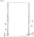
- Figs. 11 to 19 are views illustrating a method for assembling the compressor of Fig. 2 .
- the first fixing member 540 may be mounted on the first side of the inner wall 322 of the base shell 320.
- the first fixing member 540 may be fixed in the base shell 320 by, for example, a welding process S.
- this embodiment is not limited to the welding process S, that is, other processes to fix the first fixing member 540 into the base shell 320 may be applied.
- the noise reducing member 520 may be mounted to surround the inner wall 322 of the base shell 320.
- the second end 522 of the noise reducing member 520 may be inserted into the first fixing member 540.
- the compressor body 400 may be mounted inside the base shell 320.
- the compressor body 400 will be simplified in the following drawings.
- the first plate spring (see reference numeral 472 of Fig. 3 ) of the compressor body 400 may be mounted on the first fixing member 540.
- the second fixing member 560 may be mounted inside the base shell 320.
- the second fixing member 560 may be mounted on the second side of the inner wall 322 of the base shell 320 so that the second end 524 of the noise reducing member 520 may be inserted thereinto.
- the second fixing member 560 may be fixed into the base shell 320 by, for example, a press-fit process.
- this embodiment is not limited to the fitting process, that is, other processes to fix the second fixing member 560 into the base shell 320 may be applied.
- the second plate spring (see reference numeral 474 of Fig. 3 ) of the compressor body 400 may be mounted on the second fixing member 560.
- the first cover 340 may be inserted into the first side of the base shell 320 onto or into which the first fixing member 540 is mounted.
- the first cover 340 may be mounted to contact the first fixing member 540.
- the second cover 360 may be inserted into the second side of the base shell 320 onto or into which the second fixing member 560 is mounted.
- the second cover 360 may be mounted to contact the second fixing member 560.
- the first cover 340 and the second cover 360 may be mounted in reverse order.
- each of the first and second covers 340 and 360 may be coupled to the base shell 320 by, for example, the welding process S.
- this embodiment is not limited to the welding process S, that is, other processes to couple the first and second covers 340 and 360 to the base shell 320 may be applied.
- the compressor body 400 may be accommodated in the base shell 320.
- the suction inlet 100 may be mounted on the first cover 340, and the discharge outlet 200 may be mounted on the second cover 360.
- the process of assembling the linear compressor 10 may be completed. Therefore, the refrigerant introduced from the suction inlet 100 may be compressed through the compressor body 400 and then discharged through the discharge outlet 200.
- the noise reducing member 520 having a simple structure may be mounted inside the compressor casing 300 to significantly reduce noise from the compressor casing 300, in particular, noise having middle to high frequency (1 kHz to 4 kHz) transmitted from the base shell 320.
- Fig. 20 is a cross-sectional view of a compressor according to another embodiment.
- compressor 11 may be provided as a rotary compressor, in which a compression space may be defined between a roller that eccentrically rotates and a cylinder to allow a working gas, such as a refrigerant, to be suctioned into and discharged from the compression space, and the working gas may be compressed while the roller is eccentrically rotated along an inner wall of the cylinder.
- the rotary compressor 11 may include a suction inlet 1002, a discharge outlet 1004, a compressor casing 1010, a compressor body 1110, a noise reducing member 1520, a first fixing member 1540, and a second fixing member 1560.
- the suction inlet 1002 to introduce the refrigerant into the compressor casing 1010 may be mounted into the compressor casing 1010 to pass through a side surface of the compressor casing 1010.
- the discharge outlet 1004 to discharge the refrigerant out of the compressor casing 1010 may be mounted into the compressor casing 1010 to pass through an upper side of the compressor casing 1010.
- the compressor casing 1010 may define an outer appearance of the rotary compressor 11.
- the compressor casing 1010 may include a base shell 1020, and a shell cover 1060.
- the base shell 1020 may have a cylindrical shape. One side of the base shell 1020 may be open. Various components of the rotary compressor 11, such as the compressor body 1110, the noise reducing member 1520, the first fixing member 1540, and the second fixing member 1560, may be mounted on the base shell 1020. The suction inlet 1002 may pass through the base shell 1020.
- the shell cover 1060 may cover the open side of the base shell 1020 to seal the base shell 1020.
- the discharge inlet 1004 may be mounted onto the shell cover 1060 to pass through the shell cover 1060.
- the compressor body 1110 may include an electric mechanism 1120, a first compression device 1200, and a second compression device 1300.
- the electric mechanism 1120 may include a stator 1130 fixed to an inner circumferential surface of the base shell 1020, a rotor 1140 rotatably disposed in the stator 1130, and a rotational shaft 1150, which may be shrink-fitted into the rotor 1140, to rotate together with the rotor 1140.
- the electric mechanism 1120 may correspond to a constant motor or an inverter motor.
- the rotational shaft 1150 may include a shaft 1160 coupled to the rotor 1140, a first eccentric portion 1170, and a second eccentric portion 1180 eccentrically disposed on a lower portion of the shaft portion 1160 in lateral directions, respectively.
- the first eccentric portion 1170 and the second eccentric portion 1180 may be symmetrically disposed with a phase difference of about 180°.
- a first rolling piston 1220 and a second rolling piston 1320 may be rotatably coupled to the first and second eccentric portions 1170 and 1180, respectively.
- the first compression device 1200 may include a first cylinder 1210 having a ring shape and disposed within the base shell 1020 to define a first compression space V1, the first rolling piston 1220 rotatably coupled to the first eccentric portion 1170 of the rotational shaft 1150 to compress refrigerant while orbiting in the first compression space V1, a first vane 1230 that contacts an outer circumferential surface of the first rolling piston 1220 and partitions the first compression space V1 of the first cylinder 1210 into a first suction chamber and a first discharge chamber, and a first vane spring 1240 to elastically support one side of the first vein 1230.
- the second compression device 1300 may include a second cylinder 1310 having a ring shape and disposed under the first cylinder 1210 to define a second compression space V2, the second rolling piston 1320 rotatably coupled to the second eccentric portion 1180 of the rotational shaft 1150 to compress refrigerant while orbiting in the second compressing space V2, a second vane 1330 that contacts an outer circumferential surface of the second rolling piston 1320 and partitions the second compression space V2 of the second cylinder 1310 into a second suction chamber and a second discharge chamber, and a second vane spring 1340 to elastically support one side of the second vein 1330.
- a first cylinder suction portion 1250 to guide a refrigerant into the first compression space V1 may be disposed in the first cylinder 1210.
- a second cylinder suction portion 1350 to guide a refrigerant into the second compression space V2 may be disposed in the second cylinder 1310.
- the compressor body 1110 may further include an upper bearing 1480 disposed on an upper portion of the first cylinder 1210, a lower bearing 1490 disposed on a lower portion of the second cylinder 1310, and an intermediate plate 1400 disposed between the first cylinder 1210 and the second cylinder 1310 to define the first and second compression spaces together with the upper and lower bearings 1480 and 1490.
- Each of the upper and lower bearings 1480 and 1490 may have a disk shape.
- a through hole may be defined in each of the upper and lower bearings 1490 to allow the rotational shaft 1150 to pass therethrough.
- the compressor body 1110 may further include a first discharge valve 1480a disposed on the upper bearing 1480 to allow the refrigerant compressed in the first cylinder 1210 to be discharged, and a second discharge valve 1490a disposed on the lower bearing 1490 to allow the refrigerant compressed in the second cylinder 1310 to be discharged.
- the compressor body 1110 may also include a first discharge muffler 1480b disposed on the upper bearing 1480 to reduce noise generated by the refrigerant discharged through the first discharge valve 1480, and a second discharge muffler 1490b disposed below the lower bearing 1490 to reduce noise generated by the refrigerant discharged through the second discharge valve 1490a.
- the noise reducing member 1520 may be mounted on the inner wall of the base shell 1020 so that the noise reducing member 1520 may be disposed between the base shell 1020 and the compressor body 1110. As the noise reducing member 1520 is similar to that of the previous embodiment, detailed description of the noise reducing member 1520 has been omitted.
- the first and second fixing members 1540 and 1560 may be mounted inside the base shell 1020 so that the noise reducing member 1520 is fixed to the inner wall of the baser shell 1020.
- the first and second fixing members 1540 and 1560 may include a fixing portion and a protrusion similar to the previous embodiment.
- the first and second fixing members 1540 and 1560 may also be similar to the previous embodiment, and thus, repetitive descriptions of the first and second fixing members 1540 and 1560 have been omitted.
- the rotary compressor 11 has the noise reducing member 1520 having a simple structure in the compressor casing 1010 to reduce noise generated when operating, noise from the compressor casing 1010, in particular, noise having middle to high frequency (1 kHz to 4 kHz) transmitted from the base shell 1020 may be significantly reduced.
- the rotary compressor 11 may stably mount the noise reducing member 1520 on the compressor casing 1010 using the first and second fixing members 1540 and 1560.
- the noise reducing member 1520 to reduce the noise generated from the compressor and the first and second fixing members 1540 and 1560 to mount the noise reducing member 1520 on the compressor casing 1010 according to this embodiment may be applied to the rotary compressor.
- Fig. 21 is a cross-sectional view of a compressor according to another embodiment.
- compressor 12 may be provided as a scroll compressor, in which a compression space may be defined between an orbiting scroll and a fixed scroll, to allow a working gas, such as a refrigerant, to be suctioned into and discharged from the compression space, and the working gas compressed while the orbiting scroll rotates along the fixed scroll.
- the scroll compressor 12 may include a suction inlet 2001, a discharge outlet 2003, a compressor casing 2010, a compressor body 2100, a noise reducing member 2520, a first fixing member 2560, and a second fixing member 2540.
- the suction inlet 2001 to introduce the refrigerant into the compressor casing 2010 may be mounted on the compressor casing 2010 to pass through one side surface of the compressor casing 2010.
- the discharge outlet 2003 to discharge the introduced refrigerant out of the compressor casing 2010 may be mounted on the compressor casing 2010 to pass through a top surface of the compressor casing 2010.
- the compressor casing 2010 may include a base shell 2020, a first cover 2040, and a second cover 2060.
- the base shell 2020 may have an approximately cylindrical shape.
- the base shell 2020 may accommodate various components of the scroll compressor 12, such as the compressor body 2100, the noise reducing member 2520, the first fixing member 2540, and the second fixing member 2560.
- the suction inlet 2001 may be mounted on one side surface of the base shell 2020 to pass through the base shell 2020.
- the first cover 2040 may be mounted on one or at first side of the base shell 2010 to support the base shell 2020.
- the second cover 2060 may be mounted on the other or a second side of the base shell 2010 to cover the second side of the base shell 2020.
- the discharge outlet 2003 may be mounted on the second cover 2060 to pass through the second cover 2060.
- the compressor body 2100 may include a discharge cover 2105, a motor assembly 2112, 2114, and 2116, an auxiliary bearing 2117, a lower frame 2118, a main frame 2120, an orbiting scroll 2130, a fixed scroll 2140, and a back pressure chamber assembly 2150 and 2160.
- the discharge cover 2105 may be disposed under the second cover 2060 to partition an inner space of the compressor casing 2010 into a suction space S and a discharge space D.
- the suction space S may correspond to a lower side of the discharge cover 2105
- the discharge space D may correspond to an upper side of the discharge cover 2105.
- the motor assembly 2112, 2114, and 2116 may be disposed under the suction space S.
- the motor assembly 2112, 2114, and 2116 may include a stator 2112, a rotor 2114, and a drive shaft 2116.
- the stator 2112 may be coupled to an inner wall surface of the base shell 2020.
- the rotor 2114 may be rotatably disposed in the stator 2112.
- the drive shaft 2116 may be disposed to pass through a central portion of the rotor 2114.
- the auxiliary bearing 2117 may be disposed in a lower portion of the base shell 2020 so that a lower side of the rotational shaft 2116 is rotatable.
- the lower frame 2118 may be coupled to the auxiliary bearing 2117 to stably support the rotational shaft 2116.
- the lower frame 2118 may be fixed to an inner wall of the base shell 2010.
- the main frame 2120 may support an upper portion of the rotational shaft 2116 so that the rotational shaft 2116 is rotatable.
- the main frame 2120 may be fixed to the inner wall of the base shell 2010 similar to the lower frame 2118.
- a main bearing 2122 that protrudes downward may be formed on a bottom surface of the main frame 2120.
- the rotational shaft 2116 may be inserted into the main bearing 2122.
- the main bearing 2122 may have an inner wall that acts as a bearing surface to guide the rotational shaft 2116 to smoothly rotate.
- the orbiting scroll 2130 may be disposed on an upper portion of the main frame 2120.
- the orbiting scroll 2130 may include a first end plate 2133 disposed on the main frame 2120 and having an approximately disc shape.
- the orbiting scroll 2130 may further include an orbiting wrap 2134 that extends from first end plate 2133 and having a spiral shape.
- the first end plate 2133 may correspond to a main body of the orbiting scroll 2130 to define a lower portion of the orbiting scroll 2130.
- the orbiting wrap 2134 may extend from the first end plate 2133 to define an upper portion of the orbiting scroll 2130.
- the orbiting wrap 2134 and a fixed wrap 2144 of the fixed scroll 2140 which will be described hereinafter, may define a compression chamber.
- the first end plate 2133 of the orbiting scroll 2130 may orbit in a state in which the first end plate 2133 is supported by a top surface of the main frame 2120.
- An Oldham ring 2136 may be disposed between the first end plate 2133 and the main frame 2120 to prevent the orbiting scroll 2130 from rotating.
- a boss 2138, into which an upper portion of the rotational shaft 2116 may be inserted, may be disposed on a bottom surface of the first end plate 2133 of the orbiting scroll 2130 to easily transmit a rotational force of the rotational shaft 2116 to the orbiting scroll 2130.
- the fixed scroll 2140 may be disposed above the orbiting scroll 2130 and may be engaged with the orbiting scroll 2130.
- the fixed scroll 2140 may include a second end plate 2143 having a disc shape and the fixed wrap 2144, which may extend from the second end plate 2143 toward the first end plate 2133 and then be engaged with the orbiting wrap 2134 of the orbiting scroll 2130.
- the second end plate 2143 may correspond to a main body of the fixed scroll 2140 to define an upper portion of the fixed scroll 2140.
- the fixed wrap 2144 may extend downward from the second end plate 2143 to define a lower portion of the fixed scroll 2140. An end of the fixed wrap 2144 may contact the first end plate 2133, and an end of the orbiting wrap 2134 may contact the second end plate 2143.
- the back pressure chamber assembly 2150 and 2160 may be disposed on the fixed scroll 2140.
- the back pressure chamber assembly 2150 and 2160 may be fixed to an upper portion of the second end plate 2143.
- the back pressure chamber assembly 2150 and 2160 may include a back pressure plate 2150, and a floating plate 2160 separably coupled to the back pressure plate 2150.
- the noise reducing member 2520 may be mounted on the inner wall of the base shell 2020 so that the noise reducing member 2520 may be disposed between the base shell 2020 and the compressor body 2100. As the noise reducing member 2520 is similar to that of the previous embodiment, repetitive description of the noise reducing member 2520 has been omitted.
- the first and second fixing members 2540 and 2560 may be mounted inside the base shell 2020 so that the noise reducing member 2520 may be fixed to the inner wall of the baser shell 2020.
- the first and second fixing members 2540 and 2560 may include a fixing portion and a protrusion similar to the previous embodiment. As first and second fixing members 2540 and 2560 are similar to those in the previous embodiment, repetitive descriptions of the first and second fixing members 2540 and 2560 have been omitted.
- the scroll compressor 12 has the noise reducing member 2520 having a simple structure in the compressor casing 2010 to reduce noise generated when operating, noise from the compressor casing 2010, in particular, noise having middle to high frequency (1 kHz to 4 kHz) transmitted from the base shell 2020 may be significantly reduced.
- the scroll compressor 12 may stably mount the noise reducing member 2520 on the compressor casing 2010 using the first and second fixing members 2540 and 2560.
- the noise reducing member 2520 to reduce the noise generated from the compressor and the first and second fixing members 2540 and 2560 to mount the noise reducing member 2520 on the compressor casing 2010 according to this embodiment may be applied to the scroll compressor.
- Embodiments disclosed herein provide a compressor capable of reducing noise and a method of assembling a compressor.
- Embodiments disclosed herein provide a compressor that may include a compressor casing coupled to each of a suction inlet, into which a refrigerant may be introduced, and a discharge outlet, through which the refrigerant may be discharged; a compressor body mounted inside the compressor casing to compress the refrigerant suctioned in through the suction inlet, and discharge the refrigerant through the discharge outlet; a noise reducing member disposed between the compressor body and the compressor casing; and at least one fixing member mounted inside the compressor casing to fix the noise reducing member to an inner wall of the compressor casing.
- a plurality of the fixing member are provided, and the noise reducing member has both ends inserted into at least one of the fixing members to be fixed to the inner wall of the compressor casing.
- Each of the fixing members may include a fixing part or portion, one end or a first of which may be fixed to the inner wall of the compressor casing, the fixing part having a ring shape, and a protrusion part or protrusion that extends from the other or a second end of the fixing part in a direction substantially perpendicular to a radial direction of the fixing part to allow the noise reducing member to be inserted.
- the plurality of fixing members may include a first fixing member that fixes one or a first end of the noise reducing member to the inner wall of the compressor casing and a second fixing member that fixes the other or a second end of the noise reducing member to the inner wall of the compressor casing.
- the compressor body may include first and second plate springs, respectively, disposed on both ends thereof to allow the compressor body to be supported by the compressor casing.
- the first plate spring may be mounted on the first fixing member, and the second plate spring may be mounted on the second fixing member.
- Each of the fixing members may further include at least one spring mount part or mount that extends in a radial direction of the fixing part or the protrusion part.
- a plurality of the spring mount part may be provided, and the plurality of spring mount parts may be spaced a predetermined distance from each other along a circumferential direction of the fixing part or the protrusion part.
- the compressor casing may include a base shell having a cylindrical shape to accommodate the compressor body; a first cover mounted on one or a first side of the base shell, the first cover being coupled to the suction part, and a second cover mounted on the other or a second side of the base shell, the second cover being coupled to the discharge part.
- the noise reducing member may be mounted on an inner wall of the base shell.
- the noise reducing member may be mounted to surround the inner wall of the base shell.
- the noise reducing member may have a cylindrical shape which may be rolled at least three times.
- the noise reducing member may include a plurality of cylindrical parts or portions, which may overlap each other, each of which may have a slit in a side surface thereof.
- the first fixing member may be fixed to the base shell, and the noise reducing member may have one or a first end inserted into the first fixing member.
- the second fixing member may be fixed to the base shell, and the noise reducing member may have the other or a second end inserted into the second fixing member.
- Each of the first and second fixing members may be fixed to the base shell through a press-fit process or a welding process, for example.
- Each of the first and second covers may be coupled to the base shell through a welding process, for example.
- the compressor body may include a cylinder mounted along an axial direction of the compressor casing; a piston accommodated within the cylinder, the piston being reciprocated along the axial direction of the compressor casing; and a motor assembly that provides a drive force to allow the piston to be reciprocated.
- the compressor body may include a cylinder mounted along an axial direction of the compressor casing; a rolling piston that eccentrically rotates within the cylinder; and a motor assembly that provides a drive force to allow the rolling piston to eccentrically rotate.
- the compressor body may include a fixed scroll mounted along an axial direction of the compressor casing, the fixed scroll having a spiral wrap; an orbiting scroll orbiting with respect to the fixed scroll; and a motor assembly that provides a drive force to allow the orbiting scroll to orbit.
- Embodiments disclosed herein further provide a method of assembling a compressor that may include a compressor body, in which a refrigerant suctioned in through a suction inlet may be compressed and discharged to a discharge outlet.
- the method may include mounting one fixing member on one side of an inner wall of a base shell having a cylindrical shape to accommodate the compressor body; inserting one or a first end of a noise reducing member into the fixing member; inserting the compressor body into the base shell to mount the compressor body inside the noise reducing member; mounting the other fixing member on the other or a second side of the inner wall of the base shell so that the other end of the noise reducing member is inserted; mounting a first cover coupled to the suction part on one or a first side of the base shell; and mounting a second cover coupled to the discharge part on the other or a second side of the base shell.
- any reference in this specification to "one embodiment,” “an embodiment,” “example embodiment,” etc. means that a particular feature, structure, or characteristic described in connection with the embodiment is included in at least one embodiment.
- the appearances of such phrases in various places in the specification are not necessarily all referring to the same embodiment.
Abstract
Description
- The present application claims priority to Korean Patent Application No. 10-
2014-0081648 - A compressor and a method for assembling a compressor are disclosed herein.
- In general, compressors may be mechanisms that receive power from power generation devices, such as electric motors or turbines, to compress air, refrigerants, or other working gases, thereby increasing a pressure of the working gas. Compressors are being widely used in home appliances or industrial machineries, such as refrigerators and air-conditioners.
- Compressors may be largely classified into reciprocating compressors, in which a compression space into and from which a working gas is suctioned and discharged, is defined between a piston and a cylinder to allow the piston to be linearly reciprocated in the cylinder, thereby compressing the working gas; rotary compressors in which a compression space, into and from which a working gas may be suctioned or discharged, is defined between a roller that eccentrically rotates and a cylinder to allow the roller to eccentrically rotate along an inner wall of the cylinder, thereby compressing the working gas; and scroll compressors, in which a compression space into and from which a working gas is suctioned or discharged, is defined between an orbiting scroll and a fixed scroll to compress the working gas while the orbiting scroll rotates along the fixed scroll.
- A linear compressor according to the related art is disclosed in Korean Patent Registration No.
10-1307688 - However, there is a limitation in that such a linear compressor generates noise according to the operation of the compressor. In particular, noise having a middle to high frequency (1 kHz to 4 kHz) may be generated and transmitted outside of the compressor casing of the compressor. Therefore, methods for reducing the noise generated while the compressor operates are required.
- Embodiments will be described in detail with reference to the following drawings in which like reference numerals refer to like elements, and wherein:
-
Fig. 1 is a schematic diagram of a refrigerator according to an embodiment; -
Fig. 2 is an exploded perspective view of a compressor of the refrigerator ofFig. 1 ; -
Fig. 3 is a cross-sectional view of the compressor ofFIG. 2 ; -
Fig. 4 is a perspective view of a noise reducing member of the compressor ofFig. 2 ; -
Fig. 5 is an exploded perspective view of a noise reducing member according to another embodiment; -
Fig. 6 is a perspective view of a first fixing member of the compressor ofFig. 2 ; -
Fig. 7 is a rear view of the first fixing member ofFig. 6 ; -
Fig. 8 is a view illustrating a state in which the noise reducing member is fixed using the first fixing member; -
Fig. 9 is a perspective view of a second fixing member of the compressor ofFig. 2 ; -
Fig. 10 is a view illustrating a state in which the noise reducing member is fixed using the second fixing member ofFig. 9 ; -
Figs. 11 to 19 are views illustrating a method for assembling the compressor ofFig. 2 ; -
Fig. 20 is a cross-sectional view of a compressor according to another embodiment; and -
Fig. 21 is a cross-sectional view of a compressor according to another embodiment. - Embodiments will be described below in more detail with reference to the accompanying drawings. The description is intended to be illustrative, and those with ordinary skill in the technical field will understand that embodiments can be carried out in other specific forms without changing the technical idea or essential features. Also, for helping understanding, the drawings are not to actual scale, but are partially exaggerated in size.
-
Fig. 1 is a schematic diagram of a refrigerator according to an embodiment. Referring toFig. 1 , arefrigerator 1 according to an embodiment may include a plurality of devices to drive a refrigeration cycle. - In detail, the refrigerator may include a
compressor 10 to compress a refrigerant, acondenser 20 to condense the refrigerant compressed in thecompressor 10, adryer 30 to remove moisture, foreign substances, or oil from the refrigerant condensed in thecondenser 20, anexpansion device 40 to decompress the refrigerant passing through thedryer 30, and anevaporator 50 to evaporate the refrigerant decompressed in theexpansion device 40. Therefrigerator 1 may further include a condensation fan 25 to blow air toward thecondenser 20, and anevaporation fan 55 to blow air toward theevaporator 50. - The
compressor 10 may be a reciprocating compressor, a rotary compressor, or a scroll compressor, for example. Such a compressor will be described with reference to the drawings in detail. - The
expansion device 40 may include a capillary tube having a relatively small diameter. A liquid refrigerant condensed in thecondenser 20 may be introduced into thedryer 30. A gaseous refrigerant may be partially contained in the liquid refrigerant. A filter to filter the liquid refrigerant introduced into thedryer 30 may be provided in thedryer 30. - Hereinafter, the
compressor 10 according to an embodiment will be described in detail. -
Fig. 2 is an exploded perspective view of a compressor of the refrigerator ofFig. 1 .Fig. 3 is a cross-sectional view of the compressor ofFIG. 2 .Fig. 4 is a perspective view of a noise reducing member of the compressor ofFig. 2 .Fig. 5 is an exploded perspective view of a noise reducing member according to another embodiment.Fig. 6 is a perspective view of a first fixing member of the compressor ofFig. 2 .Fig. 7 is a rear view of the first fixing member ofFig. 6 .Fig. 8 is a view illustrating a state in which the noise reducing member is fixed using the first fixing member.Fig. 9 is a perspective view of a second fixing member of the compressor ofFig. 2 .Fig. 10 is a view illustrating a state in which the noise reducing member is fixed using the second fixing member ofFig. 9 . - Referring to
Figs. 2 to 10 , thecompressor 10 may be a reciprocating compressor, in which a compression space is defined between a piston and a cylinder to allow a working gas, such as a refrigerant, to be suctioned into and discharged from the compression space to compress the working gas while the piston is linearly reciprocated within the cylinder, that is, a linear compressor. Thelinear compressor 10 may include asuction inlet 100, adischarge outlet 200, acompressor casing 300, acompressor body 400, anoise reducing member 520, afirst fixing member 540, and asecond fixing member 560. - The
suction inlet 100 may introduce the refrigerant into thecompressor body 400 and may pass through afirst cover 340 of thecompressor casing 300, which will be described hereinbelow. Thedischarge outlet 200 may discharge the compressed refrigerant from thecompressor body 400 and may pass through asecond cover 360 of thecompressor casing 300, which will be described hereinbelow. - The
compressor casing 300 may accommodate thecompressor body 400 and includes abase shell 320, thefirst cover 340, and thesecond cover 360. Thebase shell 320 may accommodate thecompressor body 400 therein. Thebase shell 320 may have an approximately cylindrical shape. Thebase shell 320 may define the exterior of thelinear compressor 10, particularly, a lateral exterior of thelinear compressor 10. Thebase shell 320 may have a thickness of about 2 T. - The
first cover 340 may be mounted on a side or end of thebase shell 320. In this embodiment, the first cover 114 may be mounted on a first side or end of thebase shell 320. Thesuction inlet 100 may passes through thefirst cover 340 to introduce the refrigerant into thecompressor body 400. - The
second cover 360 may be mounted on another side or end of thebase shell 320. In this embodiment, thesecond cover 360 is mounted on a second side or end of thebase shell 320, which is opposite to thefirst cover 340. Thedischarge outlet 200 may pass through thesecond cover 360 to discharge the compressed refrigerant. - The
compressor body 400 may compress the refrigerant introduced through thesuction inlet 100 and discharge the compressed refrigerant through thedischarge outlet 200. Thecompressor body 400 may include acylinder 420 provided in thebase shell 320, apiston 430 linearly reciprocated within thecylinder 420, and amotor assembly 440, which may be a linear motor that applies a drive force to thepiston 430. - The
compressor body 400 may further include asuction muffler 450. The refrigerant suctioned in through thesuction inlet 100 may flow into thepiston 430 via thesuction muffler 450. While the refrigerant passes through thesuction muffler 450, noise may be reduced. Thesuction muffler 450 may be configured by coupling afirst muffler 451 to asecond muffler 453. At least a portion of thesuction muffler 450 may be disposed within thepiston 430. - The
piston 430 may include apiston body 431 having an approximately cylindrical shape, and apiston flange 432 that extends from thepiston body 431 in a radial direction. Thepiston body 431 may be reciprocated within thecylinder 420, and thepiston flange 432 may be reciprocated outside of thecylinder 420. - The
piston 430 may be formed of a nonmagnetic material, such as an aluminum material, such as aluminum or an aluminum alloy. As thepiston 430 may be formed of the aluminum material, a magnetic flux generated in themotor assembly 440 may not be transmitted into thepiston 430, and thus, may be prevented from leaking outside of thepiston 430. Thepiston 430 may be manufactured by, for example, a forging process. - The
cylinder 420 may be formed of a nonmagnetic material, such as an aluminum material, such as aluminum or an aluminum alloy. Thecylinder 420 and thepiston 430 may have a same material composition, that is, a same kind and composition. - As the
cylinder 420 may be formed of the aluminum material, the magnetic flux generated in themotor assembly 440 may not be transmitted into thecylinder 420, and thus, may be prevented from leaking outside of thecylinder 420. Thecylinder 420 may be manufactured by, for example, an extruding rod processing process. - As the
piston 430 may be formed of the same material, for example, aluminum, as thecylinder 420, thepiston 430 may have a same thermal expansion coefficient as thecylinder 420. When thelinear compressor 10 operates, a high-temperature (a temperature of about 100 °C) environment may be created within thecompressor casing 300. Thus, as thepiston 430 and thecylinder 420 may have the same thermal expansion coefficient, thepiston 430 and thecylinder 420 may be thermally deformed by a same degree. As a result, thepiston 430 and thecylinder 420 may be thermally deformed with sizes and in directions different from each other to prevent thepiston 430 from interfering with thecylinder 420 while thepiston 430 moves. - The
cylinder 420 may be configured to accommodate at least a portion of thesuction muffler 450 and at least a portion of thepiston 430. Thecylinder 420 may have a compression space P, in which the refrigerant may be compressed by thepiston 430. Asuction hole 433, through which the refrigerant may be introduced into the compression space P, may be defined in a front portion of thepiston 430, and asuction valve 435 to selectively open thesuction hole 433 may be disposed on or at a front side of thesuction hole 433. A coupling hole, to which a predetermined coupling member may be coupled, may be defined in an approximately central portion of thesuction valve 435. - A
discharge cover 460 that defines a discharge space or discharge passage for the refrigerant discharged from the compression space P and adischarge valve assembly discharge cover 460 to selectively discharge the refrigerant compressed in the compression space P may be provided at a front side of the compression space P. Thedischarge valve assembly discharge valve 461 to introduce the refrigerant into the discharge space of thedischarge cover 460 when a pressure within the compression space P is above a predetermined discharge pressure, avalve spring 462 disposed between thedischarge valve 461 and thedischarge cover 460 to apply an elastic force in an axial direction, and astopper 463 to restrict deformation of thevalve spring 462. - The compression space P may refer to a space defined between the
suction valve 435 and thedischarge valve 461. The term "axial direction" may refer to a direction in which thepiston 530 is reciprocated. The term "radial direction" may refer to a direction perpendicular to the direction in which thepiston 430 is reciprocated, that is, a horizontal direction inFig. 2 . - The
stopper 463 may be seated on thedischarge cover 460, and thevalve spring 462 may be seated at a rear side of thestopper 463. Thedischarge valve 461 may be coupled to thevalve spring 462, and a rear portion or rear surface of thedischarge valve 461 may be supported by a front surface of thecylinder 420. Thevalve spring 462 may include a plate spring, for example. - The
suction valve 435 may be disposed on or at a first side of the compression space P, and thedischarge valve 461 may be disposed on or at a second side of the compression space P, that is, a side opposite of thesuction valve 435. While thepiston 430 is linearly reciprocated within thecylinder 420, when the pressure of the compression space P is below the predetermined discharge pressure and a predetermined suction pressure, thesuction valve 435 may be opened to suction the refrigerant into the compression space P. On the other hand, when the pressure of the compression space P is above the predetermined suction pressure, thesuction valve 435 may compress the refrigerant of the compression space P in a state in which thesuction valve 435 is closed. When the pressure of the compression space P is above the predetermined discharge pressure, thevalve spring 462 may be deformed to open thedischarge valve 461. The refrigerant may be discharged from the compression space P into the discharge space of thedischarge cover 460. - The refrigerant flowing into the discharge space of the
discharge cover 460 may be introduced into aloop pipe 465. Theloop pipe 465 may be coupled to thedischarge cover 460 to extend to thedischarge outlet 200, thereby guiding the compressed refrigerant in the discharge space into thedischarge outlet 200. For example, theloop pipe 465 may have a shape which is wound in a predetermined direction and extends in a rounded shape. Theloop pipe 465 may be coupled to thedischarge outlet 200. - The
compressor body 400 may further include aframe 410. Theframe 410 may fix thecylinder 420 and be coupled to thecylinder 420 by a separate coupling member, for example. Theframe 410 may be disposed to surround thecylinder 420. That is, thecylinder 420 may be accommodated within theframe 410. Thedischarge cover 460 may be coupled to a front surface of theframe 410. - At least a portion of the high-pressure gaseous refrigerant discharged through the opened
discharge valve 461 may flow toward an outer circumferential surface of thecylinder 420 through a space formed at a portion at which thecylinder 420 and theframe 410 are coupled to each other. - The refrigerant may be introduced into the
cylinder 420 through a gas inflow and a nozzle, which may be defined in thecylinder 420. The introduced refrigerant may flow into a space defined between thepiston 430 and thecylinder 420 to allow an outer circumferential surface of thepiston 430 to be spaced apart from an inner circumferential surface of thecylinder 420. Thus, the introduced refrigerant may serve as a "gas bearing" that reduces friction between thepiston 430 and thecylinder 420 while thepiston 430 is reciprocated. - The
motor assembly 440 may includeouter stators frame 410 and disposed to surround thecylinder 420, aninner stator 448 disposed to be spaced inward from theouter stators permanent magnet 446 disposed in a space between theouter stators permanent magnet 446 may be linearly reciprocated by a mutual electromagnetic force between theouter stators inner stator 448. Thepermanent magnet 446 may be provided as a single magnet having one polarity, or may include a plurality of magnets having three polarities. - The
permanent magnet 446 may be coupled to thepiston 430 by aconnection member 438, for example. In detail, theconnection member 438 may be coupled to thepiston flange 432 and be bent to extend toward the permanent 446. As thepermanent magnet 446 is reciprocated, thepiston 430 may be reciprocated together with thepermanent magnet 446 in the axial direction. - The
motor assembly 440 may further include a fixingmember 447 to fix thepermanent magnet 446 to theconnection member 438. The fixingmember 447 may be formed of a composition in which a glass fiber or carbon fiber is mixed with a resin. The fixingmember 447 may surround an outside of thepermanent magnet 446 to firmly maintain a coupled state between thepermanent magnet 446 and theconnection member 438. - The
outer stators coil winding bodies 443 and 445, and astator core 441. Thecoil winding bodies 443 and 445 may include a bobbin 443 and acoil 445 wound in a circumferential direction of the bobbin 443. Thecoil 445 may have a polygonal cross-section, for example, a hexagonal cross-section. Thestator core 441 may be manufactured by stacking a plurality of laminations in the circumferential direction and be disposed to surround thecoil winding bodies 443 and 445. - A
stator cover 449 may be disposed at one side of theouter stators outer stators frame 410, and a second side of theouter stators stator cover 449. Theinner stator 448 may be fixed to a circumference of thecylinder 420. Also, in theinner stator 448, a plurality of laminations may be stacked in a circumferential direction outside thecylinder 420. - The
compressor body 400 may further include asupport 437 to support thepiston 430, and aback cover 470 spring-coupled to thesupport 437. Thesupport 437 may be coupled to thepiston flange 432 and theconnection member 438 by a predetermined coupling member, for example. - A
suction guide 455 may be coupled to a front portion of theback cover 470. Thesuction guide 455 may guide the refrigerant suctioned through thesuction inlet 100 to introduce the refrigerant into thesuction muffler 450. - The
compressor body 400 may include a plurality ofsprings 476 which may be adjustable in natural frequency to allow thepiston 430 to perform a resonant motion. The plurality ofsprings 476 may include a first spring (not shown) supported between thesupport 437 and thestator cover 449 and a second spring supported between thesupport 437 and theback cover 470. - The
compressor body 400 may additionally include a pair of plate springs 472 and 474 to support thecompressor body 400 by thebase shell 320. The pair of plate springs 472 and 474 may includes afirst plate spring 472 and asecond plate spring 474. - The
first plate spring 472 may be mounted on the first fixingmember 540, which will be described hereinbelow, and thesecond plate spring 474 may be mounted on thesecond plate spring 474, which will be described hereinbelow. However, the first and second plate springs 472 and 474 are not limited to mounting positions thereof. For example, if thecompressor body 400 is supported by thebase shell 320, the first and second plate springs 472 and 474 may be coupled to the first andsecond covers - The
noise reducing member 520 may surround aninner wall 322 of thebase shell 320. In this embodiment, as thenoise reducing member 520 is mounted on an inner side of thebase shell 320, thebase shell 320 may substantially increase in thickness. Thus, while thecompressor body 400 operates, noise generated from thecompressor body 400 may not be heard outside of thecompressor casing 300. - The
noise reducing member 520 may be formed of a steel plate having a thickness of about 0.4 T to about 1.0 T. Thenoise reducing member 520 may have a cylindrical shape, which may be rolled at least once. For this, thenoise reducing member 520 may be formed of spring steel (SK5) having strong elasticity, or steel (SA1010) having strong elasticity among general steel so as to smoothly perform rolling. - As illustrated in
Fig. 4 , thenoise reducing member 520 may be formed by rolling one steel plate several times so that thenoise reducing member 520 has a rolled cylindrical shape. For example, thenoise reducing member 520 may be formed by rolling the steel plate at least one to ten times. - Alternatively, illustrated in
Fig. 5 , thenoise reducing member 530 may be formed by overlapping a plurality ofcylindrical portions cylindrical portions noise reducing member 530.Slits cylindrical portions slits cylindrical portions cylindrical portions slits noise reducing member 530 may be formed by overlapping the plurality ofcylindrical portions noise reducing member 520 having a thickness of about 0.4 T and rolled three times. - Referring to
Fig. 6 , the first fixingmember 540 may include a fixingportion 542, aprotrusion 544, at least onespring mount 545, and aspring support 546. The fixingportion 542 may have a ring shape. One or a first end of the fixingportion 542 may be fixed to theinner wall 322 of thebase shell 320. - The
protrusion 544 may extend from the other or a second end of the fixingportion 542 so that theprotrusion 544 has a predetermined thickness in a direction perpendicular to a radial direction of the fixingportion 542 to allow thenoise reducing member 520 to be inserted into the first fixingmember 540. - Each at least one
spring mount 545 may extend in a radial direction of theprotrusion 544. The at least onespring mount 545 may include a plurality of spring mounts 545. In this embodiment, three spring mounts 545 are shown; however, embodiments are not limited thereto. Each of the spring mounts 545 may be coupled to thefirst plate spring 472 through a coupling member, such as a bolt, for example. - The
spring support 546 may be disposed on a rear surface of theprotrusion 544 to support thefirst plate spring 545. Thespring support 546 may be disposed in a same line as the plurality of spring mounts 545. - Thus, the first fixing
member 540 may fix one or a first end of thenoise reducing member 520 to theinner wall 322 of thebase shell 320 and be coupled to thefirst cover 340. Also, the first fixingmember 540 may stably support thefirst plate spring 472. - The
second fixing member 560 may include a fixingportion 562 and aprotrusion 564. One or a first end of the fixingportion 562 may be fixed to theinner wall 322 of thebase shell 320 similar to the fixingportion 542 of the first fixingmember 540. - The
protrusion 562 may extend from the other or a second end of the fixingportion 562 so that theprotrusion 562 has a predetermined thickness in a direction perpendicular to a radial direction of the fixingportion 562 to allow thenoise reducing member 520 to be inserted into the second fixingmember 560. - Thus, the second fixing
member 560 may fix the other or a second end of thenoise reducing member 520 to theinner wall 322 of thebase shell 320 and be coupled to thesecond cover 360. Also, the above-describedsecond plate spring 474 may be mounted on the second fixingmember 560. Although not shown, a spring mount and a spring support may be disposed on the second fixingmember 560 similar to those of the first fixingmember 540. If the second fixingmember 560 has structure for stably supporting theplate spring 474, theplate spring mount 545 and thespring support 546 may be omitted. - According to this embodiment, the
noise reducing member 520 to prevent noise generated while thelinear compressor 10 operates may be stably mounted on thecompressor casing 300 using the first and second fixingmembers - Hereinafter, a method for assembling the
linear compressor 10 including thenoise reducing member 520 according to an embodiment will be described in detail. -
Figs. 11 to 19 are views illustrating a method for assembling the compressor ofFig. 2 . Referring toFigs. 11 and12 , the first fixingmember 540 may be mounted on the first side of theinner wall 322 of thebase shell 320. Thefirst fixing member 540 may be fixed in thebase shell 320 by, for example, a welding process S. However, this embodiment is not limited to the welding process S, that is, other processes to fix the first fixingmember 540 into thebase shell 320 may be applied. - Referring to
Fig. 13 , thenoise reducing member 520 may be mounted to surround theinner wall 322 of thebase shell 320. Thesecond end 522 of thenoise reducing member 520 may be inserted into the first fixingmember 540. - Referring to
Fig. 14 , thecompressor body 400 may be mounted inside thebase shell 320. For convenience of the explanation, thecompressor body 400 will be simplified in the following drawings. As described above, the first plate spring (seereference numeral 472 ofFig. 3 ) of thecompressor body 400 may be mounted on the first fixingmember 540. - Referring to
Fig. 15 , after thecompressor body 400 is mounted on the inside of thebase shell 320, the second fixingmember 560 may be mounted inside thebase shell 320. Thesecond fixing member 560 may be mounted on the second side of theinner wall 322 of thebase shell 320 so that thesecond end 524 of thenoise reducing member 520 may be inserted thereinto. Thesecond fixing member 560 may be fixed into thebase shell 320 by, for example, a press-fit process. However, this embodiment is not limited to the fitting process, that is, other processes to fix the second fixingmember 560 into thebase shell 320 may be applied. As described above, the second plate spring (seereference numeral 474 ofFig. 3 ) of thecompressor body 400 may be mounted on the second fixingmember 560. - Referring to
Fig. 16 , thefirst cover 340 may be inserted into the first side of thebase shell 320 onto or into which the first fixingmember 540 is mounted. Thefirst cover 340 may be mounted to contact the first fixingmember 540. - Referring to
Fig. 17 , thesecond cover 360 may be inserted into the second side of thebase shell 320 onto or into which the second fixingmember 560 is mounted. Thesecond cover 360 may be mounted to contact the second fixingmember 560. Thefirst cover 340 and thesecond cover 360 may be mounted in reverse order. - Referring to
Fig. 18 , each of the first andsecond covers base shell 320 by, for example, the welding process S. However, this embodiment is not limited to the welding process S, that is, other processes to couple the first andsecond covers base shell 320 may be applied. Thus, thecompressor body 400 may be accommodated in thebase shell 320. - Referring to
Fig. 19 , thesuction inlet 100 may be mounted on thefirst cover 340, and thedischarge outlet 200 may be mounted on thesecond cover 360. Thus, the process of assembling thelinear compressor 10 may be completed. Therefore, the refrigerant introduced from thesuction inlet 100 may be compressed through thecompressor body 400 and then discharged through thedischarge outlet 200. - Through the above-described assembling process, in the
linear compressor 10 according to this embodiment, thenoise reducing member 520 having a simple structure may be mounted inside thecompressor casing 300 to significantly reduce noise from thecompressor casing 300, in particular, noise having middle to high frequency (1 kHz to 4 kHz) transmitted from thebase shell 320. -
Fig. 20 is a cross-sectional view of a compressor according to another embodiment. Referring toFig. 20 ,compressor 11 may be provided as a rotary compressor, in which a compression space may be defined between a roller that eccentrically rotates and a cylinder to allow a working gas, such as a refrigerant, to be suctioned into and discharged from the compression space, and the working gas may be compressed while the roller is eccentrically rotated along an inner wall of the cylinder. Therotary compressor 11 may include asuction inlet 1002, adischarge outlet 1004, acompressor casing 1010, acompressor body 1110, anoise reducing member 1520, afirst fixing member 1540, and asecond fixing member 1560. - The
suction inlet 1002 to introduce the refrigerant into thecompressor casing 1010 may be mounted into thecompressor casing 1010 to pass through a side surface of thecompressor casing 1010. Thedischarge outlet 1004 to discharge the refrigerant out of thecompressor casing 1010 may be mounted into thecompressor casing 1010 to pass through an upper side of thecompressor casing 1010. - The
compressor casing 1010 may define an outer appearance of therotary compressor 11. Thecompressor casing 1010 may include abase shell 1020, and ashell cover 1060. - The
base shell 1020 may have a cylindrical shape. One side of thebase shell 1020 may be open. Various components of therotary compressor 11, such as thecompressor body 1110, thenoise reducing member 1520, thefirst fixing member 1540, and thesecond fixing member 1560, may be mounted on thebase shell 1020. Thesuction inlet 1002 may pass through thebase shell 1020. - The
shell cover 1060 may cover the open side of thebase shell 1020 to seal thebase shell 1020. Thedischarge inlet 1004 may be mounted onto theshell cover 1060 to pass through theshell cover 1060. - The
compressor body 1110 may include anelectric mechanism 1120, a first compression device 1200, and a second compression device 1300. Theelectric mechanism 1120 may include astator 1130 fixed to an inner circumferential surface of thebase shell 1020, arotor 1140 rotatably disposed in thestator 1130, and arotational shaft 1150, which may be shrink-fitted into therotor 1140, to rotate together with therotor 1140. Theelectric mechanism 1120 may correspond to a constant motor or an inverter motor. - The
rotational shaft 1150 may include ashaft 1160 coupled to therotor 1140, a firsteccentric portion 1170, and a second eccentric portion 1180 eccentrically disposed on a lower portion of theshaft portion 1160 in lateral directions, respectively. - The first
eccentric portion 1170 and the second eccentric portion 1180 may be symmetrically disposed with a phase difference of about 180°. Afirst rolling piston 1220 and asecond rolling piston 1320 may be rotatably coupled to the first and secondeccentric portions 1170 and 1180, respectively. - The first compression device 1200 may include a
first cylinder 1210 having a ring shape and disposed within thebase shell 1020 to define a first compression space V1, thefirst rolling piston 1220 rotatably coupled to the firsteccentric portion 1170 of therotational shaft 1150 to compress refrigerant while orbiting in the first compression space V1, afirst vane 1230 that contacts an outer circumferential surface of thefirst rolling piston 1220 and partitions the first compression space V1 of thefirst cylinder 1210 into a first suction chamber and a first discharge chamber, and afirst vane spring 1240 to elastically support one side of thefirst vein 1230. - The second compression device 1300 may include a
second cylinder 1310 having a ring shape and disposed under thefirst cylinder 1210 to define a second compression space V2, thesecond rolling piston 1320 rotatably coupled to the second eccentric portion 1180 of therotational shaft 1150 to compress refrigerant while orbiting in the second compressing space V2, asecond vane 1330 that contacts an outer circumferential surface of thesecond rolling piston 1320 and partitions the second compression space V2 of thesecond cylinder 1310 into a second suction chamber and a second discharge chamber, and asecond vane spring 1340 to elastically support one side of thesecond vein 1330. - A first
cylinder suction portion 1250 to guide a refrigerant into the first compression space V1 may be disposed in thefirst cylinder 1210. A secondcylinder suction portion 1350 to guide a refrigerant into the second compression space V2 may be disposed in thesecond cylinder 1310. - The
compressor body 1110 may further include anupper bearing 1480 disposed on an upper portion of thefirst cylinder 1210, alower bearing 1490 disposed on a lower portion of thesecond cylinder 1310, and anintermediate plate 1400 disposed between thefirst cylinder 1210 and thesecond cylinder 1310 to define the first and second compression spaces together with the upper andlower bearings lower bearings lower bearings 1490 to allow therotational shaft 1150 to pass therethrough. - The
compressor body 1110 may further include afirst discharge valve 1480a disposed on theupper bearing 1480 to allow the refrigerant compressed in thefirst cylinder 1210 to be discharged, and asecond discharge valve 1490a disposed on thelower bearing 1490 to allow the refrigerant compressed in thesecond cylinder 1310 to be discharged. Thecompressor body 1110 may also include afirst discharge muffler 1480b disposed on theupper bearing 1480 to reduce noise generated by the refrigerant discharged through thefirst discharge valve 1480, and asecond discharge muffler 1490b disposed below thelower bearing 1490 to reduce noise generated by the refrigerant discharged through thesecond discharge valve 1490a. - The
noise reducing member 1520 may be mounted on the inner wall of thebase shell 1020 so that thenoise reducing member 1520 may be disposed between thebase shell 1020 and thecompressor body 1110. As thenoise reducing member 1520 is similar to that of the previous embodiment, detailed description of thenoise reducing member 1520 has been omitted. - The first and
second fixing members base shell 1020 so that thenoise reducing member 1520 is fixed to the inner wall of thebaser shell 1020. The first andsecond fixing members second fixing members second fixing members - Similar to the previous embodiment, as the
rotary compressor 11 according to this embodiment has thenoise reducing member 1520 having a simple structure in thecompressor casing 1010 to reduce noise generated when operating, noise from thecompressor casing 1010, in particular, noise having middle to high frequency (1 kHz to 4 kHz) transmitted from thebase shell 1020 may be significantly reduced. - Also, similar to the previous embodiment, the
rotary compressor 11 according to this embodiment may stably mount thenoise reducing member 1520 on thecompressor casing 1010 using the first andsecond fixing members noise reducing member 1520 to reduce the noise generated from the compressor and the first andsecond fixing members noise reducing member 1520 on thecompressor casing 1010 according to this embodiment may be applied to the rotary compressor. -
Fig. 21 is a cross-sectional view of a compressor according to another embodiment. Referring toFig. 21 ,compressor 12 may be provided as a scroll compressor, in which a compression space may be defined between an orbiting scroll and a fixed scroll, to allow a working gas, such as a refrigerant, to be suctioned into and discharged from the compression space, and the working gas compressed while the orbiting scroll rotates along the fixed scroll. Thescroll compressor 12 may include asuction inlet 2001, adischarge outlet 2003, acompressor casing 2010, acompressor body 2100, anoise reducing member 2520, afirst fixing member 2560, and asecond fixing member 2540. - The
suction inlet 2001 to introduce the refrigerant into thecompressor casing 2010 may be mounted on thecompressor casing 2010 to pass through one side surface of thecompressor casing 2010. Thedischarge outlet 2003 to discharge the introduced refrigerant out of thecompressor casing 2010 may be mounted on thecompressor casing 2010 to pass through a top surface of thecompressor casing 2010. - The
compressor casing 2010 may include abase shell 2020, afirst cover 2040, and asecond cover 2060. Thebase shell 2020 may have an approximately cylindrical shape. Thebase shell 2020 may accommodate various components of thescroll compressor 12, such as thecompressor body 2100, thenoise reducing member 2520, thefirst fixing member 2540, and thesecond fixing member 2560. Thesuction inlet 2001 may be mounted on one side surface of thebase shell 2020 to pass through thebase shell 2020. - The
first cover 2040 may be mounted on one or at first side of thebase shell 2010 to support thebase shell 2020. Thesecond cover 2060 may be mounted on the other or a second side of thebase shell 2010 to cover the second side of thebase shell 2020. Thedischarge outlet 2003 may be mounted on thesecond cover 2060 to pass through thesecond cover 2060. - The
compressor body 2100 may include adischarge cover 2105, amotor assembly auxiliary bearing 2117, alower frame 2118, amain frame 2120, anorbiting scroll 2130, afixed scroll 2140, and a backpressure chamber assembly - The
discharge cover 2105 may be disposed under thesecond cover 2060 to partition an inner space of thecompressor casing 2010 into a suction space S and a discharge space D. The suction space S may correspond to a lower side of thedischarge cover 2105, and the discharge space D may correspond to an upper side of thedischarge cover 2105. - The
motor assembly motor assembly stator 2112, arotor 2114, and adrive shaft 2116. - The
stator 2112 may be coupled to an inner wall surface of thebase shell 2020. Therotor 2114 may be rotatably disposed in thestator 2112. Thedrive shaft 2116 may be disposed to pass through a central portion of therotor 2114. - The
auxiliary bearing 2117 may be disposed in a lower portion of thebase shell 2020 so that a lower side of therotational shaft 2116 is rotatable. Thelower frame 2118 may be coupled to theauxiliary bearing 2117 to stably support therotational shaft 2116. Thelower frame 2118 may be fixed to an inner wall of thebase shell 2010. - The
main frame 2120 may support an upper portion of therotational shaft 2116 so that therotational shaft 2116 is rotatable. Themain frame 2120 may be fixed to the inner wall of thebase shell 2010 similar to thelower frame 2118. Amain bearing 2122 that protrudes downward may be formed on a bottom surface of themain frame 2120. Therotational shaft 2116 may be inserted into themain bearing 2122. Themain bearing 2122 may have an inner wall that acts as a bearing surface to guide therotational shaft 2116 to smoothly rotate. - The
orbiting scroll 2130 may be disposed on an upper portion of themain frame 2120. Theorbiting scroll 2130 may include afirst end plate 2133 disposed on themain frame 2120 and having an approximately disc shape. Theorbiting scroll 2130 may further include anorbiting wrap 2134 that extends fromfirst end plate 2133 and having a spiral shape. - The
first end plate 2133 may correspond to a main body of theorbiting scroll 2130 to define a lower portion of theorbiting scroll 2130. Theorbiting wrap 2134 may extend from thefirst end plate 2133 to define an upper portion of theorbiting scroll 2130. Theorbiting wrap 2134 and a fixedwrap 2144 of the fixedscroll 2140, which will be described hereinafter, may define a compression chamber. - The
first end plate 2133 of theorbiting scroll 2130 may orbit in a state in which thefirst end plate 2133 is supported by a top surface of themain frame 2120. AnOldham ring 2136 may be disposed between thefirst end plate 2133 and themain frame 2120 to prevent theorbiting scroll 2130 from rotating. Aboss 2138, into which an upper portion of therotational shaft 2116 may be inserted, may be disposed on a bottom surface of thefirst end plate 2133 of theorbiting scroll 2130 to easily transmit a rotational force of therotational shaft 2116 to theorbiting scroll 2130. - The fixed
scroll 2140 may be disposed above theorbiting scroll 2130 and may be engaged with theorbiting scroll 2130. The fixedscroll 2140 may include asecond end plate 2143 having a disc shape and the fixedwrap 2144, which may extend from thesecond end plate 2143 toward thefirst end plate 2133 and then be engaged with theorbiting wrap 2134 of theorbiting scroll 2130. Thesecond end plate 2143 may correspond to a main body of the fixedscroll 2140 to define an upper portion of the fixedscroll 2140. The fixedwrap 2144 may extend downward from thesecond end plate 2143 to define a lower portion of the fixedscroll 2140. An end of the fixedwrap 2144 may contact thefirst end plate 2133, and an end of theorbiting wrap 2134 may contact thesecond end plate 2143. - The back
pressure chamber assembly scroll 2140. The backpressure chamber assembly second end plate 2143. The backpressure chamber assembly back pressure plate 2150, and a floatingplate 2160 separably coupled to theback pressure plate 2150. - The
noise reducing member 2520 may be mounted on the inner wall of thebase shell 2020 so that thenoise reducing member 2520 may be disposed between thebase shell 2020 and thecompressor body 2100. As thenoise reducing member 2520 is similar to that of the previous embodiment, repetitive description of thenoise reducing member 2520 has been omitted. - The first and
second fixing members base shell 2020 so that thenoise reducing member 2520 may be fixed to the inner wall of thebaser shell 2020. The first andsecond fixing members second fixing members second fixing members - Similar to the previous embodiment, as the
scroll compressor 12 according to this embodiment has thenoise reducing member 2520 having a simple structure in thecompressor casing 2010 to reduce noise generated when operating, noise from thecompressor casing 2010, in particular, noise having middle to high frequency (1 kHz to 4 kHz) transmitted from thebase shell 2020 may be significantly reduced. - Also, similar to as the previous embodiment, the
scroll compressor 12 according to this embodiment may stably mount thenoise reducing member 2520 on thecompressor casing 2010 using the first andsecond fixing members noise reducing member 2520 to reduce the noise generated from the compressor and the first andsecond fixing members noise reducing member 2520 on thecompressor casing 2010 according to this embodiment may be applied to the scroll compressor. - Embodiments disclosed herein provide a compressor capable of reducing noise and a method of assembling a compressor.
- Embodiments disclosed herein provide a compressor that may include a compressor casing coupled to each of a suction inlet, into which a refrigerant may be introduced, and a discharge outlet, through which the refrigerant may be discharged; a compressor body mounted inside the compressor casing to compress the refrigerant suctioned in through the suction inlet, and discharge the refrigerant through the discharge outlet; a noise reducing member disposed between the compressor body and the compressor casing; and at least one fixing member mounted inside the compressor casing to fix the noise reducing member to an inner wall of the compressor casing. A plurality of the fixing member are provided, and the noise reducing member has both ends inserted into at least one of the fixing members to be fixed to the inner wall of the compressor casing.
- Each of the fixing members may include a fixing part or portion, one end or a first of which may be fixed to the inner wall of the compressor casing, the fixing part having a ring shape, and a protrusion part or protrusion that extends from the other or a second end of the fixing part in a direction substantially perpendicular to a radial direction of the fixing part to allow the noise reducing member to be inserted. The plurality of fixing members may include a first fixing member that fixes one or a first end of the noise reducing member to the inner wall of the compressor casing and a second fixing member that fixes the other or a second end of the noise reducing member to the inner wall of the compressor casing.
- The compressor body may include first and second plate springs, respectively, disposed on both ends thereof to allow the compressor body to be supported by the compressor casing. The first plate spring may be mounted on the first fixing member, and the second plate spring may be mounted on the second fixing member.
- Each of the fixing members may further include at least one spring mount part or mount that extends in a radial direction of the fixing part or the protrusion part. A plurality of the spring mount part may be provided, and the plurality of spring mount parts may be spaced a predetermined distance from each other along a circumferential direction of the fixing part or the protrusion part.
- The compressor casing may include a base shell having a cylindrical shape to accommodate the compressor body; a first cover mounted on one or a first side of the base shell, the first cover being coupled to the suction part, and a second cover mounted on the other or a second side of the base shell, the second cover being coupled to the discharge part. The noise reducing member may be mounted on an inner wall of the base shell. The noise reducing member may be mounted to surround the inner wall of the base shell.
- The noise reducing member may have a cylindrical shape which may be rolled at least three times. The noise reducing member may include a plurality of cylindrical parts or portions, which may overlap each other, each of which may have a slit in a side surface thereof.
- The first fixing member may be fixed to the base shell, and the noise reducing member may have one or a first end inserted into the first fixing member. The second fixing member may be fixed to the base shell, and the noise reducing member may have the other or a second end inserted into the second fixing member. Each of the first and second fixing members may be fixed to the base shell through a press-fit process or a welding process, for example. Each of the first and second covers may be coupled to the base shell through a welding process, for example.
- The compressor body may include a cylinder mounted along an axial direction of the compressor casing; a piston accommodated within the cylinder, the piston being reciprocated along the axial direction of the compressor casing; and a motor assembly that provides a drive force to allow the piston to be reciprocated. The compressor body may include a cylinder mounted along an axial direction of the compressor casing; a rolling piston that eccentrically rotates within the cylinder; and a motor assembly that provides a drive force to allow the rolling piston to eccentrically rotate. The compressor body may include a fixed scroll mounted along an axial direction of the compressor casing, the fixed scroll having a spiral wrap; an orbiting scroll orbiting with respect to the fixed scroll; and a motor assembly that provides a drive force to allow the orbiting scroll to orbit.
- Embodiments disclosed herein further provide a method of assembling a compressor that may include a compressor body, in which a refrigerant suctioned in through a suction inlet may be compressed and discharged to a discharge outlet. The method may include mounting one fixing member on one side of an inner wall of a base shell having a cylindrical shape to accommodate the compressor body; inserting one or a first end of a noise reducing member into the fixing member; inserting the compressor body into the base shell to mount the compressor body inside the noise reducing member; mounting the other fixing member on the other or a second side of the inner wall of the base shell so that the other end of the noise reducing member is inserted; mounting a first cover coupled to the suction part on one or a first side of the base shell; and mounting a second cover coupled to the discharge part on the other or a second side of the base shell.
- Any reference in this specification to "one embodiment," "an embodiment," "example embodiment," etc., means that a particular feature, structure, or characteristic described in connection with the embodiment is included in at least one embodiment. The appearances of such phrases in various places in the specification are not necessarily all referring to the same embodiment. Further, when a particular feature, structure, or characteristic is described in connection with any embodiment, it is submitted that it is within the purview of one skilled in the art to effect such feature, structure, or characteristic in connection with other ones of the embodiments.
- Although embodiments have been described with reference to a number of illustrative embodiments thereof, it should be understood that numerous other modifications and embodiments can be devised by those skilled in the art that will fall within the scope of the principles of this disclosure. More particularly, various variations and modifications are possible in the component parts and/or arrangements of the subject combination arrangement within the scope of the disclosure, the drawings and the appended claims. In addition to variations and modifications in the component parts and/or arrangements, alternative uses will also be apparent to those skilled in the art.
- The following items represent further aspects of the present invention.
- 1. A compressor, comprising:
- a compressor casing (300) coupled to a suction inlet (100) for introducing a refrigerant into the compressor and a discharge outlet (200) for discharging the refrigerant from the compressor;
- a compressor body (400) mounted inside the compressor casing, being configured to compress the refrigerant suctioned in through the suction inlet, and thereafter to discharge the refrigerant through the discharge outlet;
- a noise reducing member (520, 530) interposed between the compressor body and the compressor casing; and
- at least one fixing member (540, 560) mounted inside the compressor casing to fix the noise reducing member to an inner wall of the compressor casing.
- 2. The compressor according to
item 1, wherein the at least one fixing member (540, 560) comprises a plurality of fixing members, and wherein each of opposite ends of the noise reducing member (520, 530) is inserted into at least one of the plurality of fixing members, to be fixed to the inner wall of the compressor casing. - 3. The compressor according to item 2, wherein each of the plurality of fixing members (540, 560) comprises:
- a fixing portion (542, 562) fixed to the inner wall of the compressor casing, the fixing portion having a ring shape; and
- a protrusion (544, 564) that extends from the fixing portion in a direction substantially perpendicular to a radial direction of the fixing portion.
- 4. The compressor according to item 2 or 3, wherein the plurality of fixing members (540, 560) comprises:
- a first fixing member (540) configured to fix a first end of the noise reducing member (520, 530) to the inner wall of the compressor casing (300); and
- a second fixing member (560) configured to fix a second end of the noise reducing member (520, 530) to the inner wall of the compressor casing (300).
- 5. The compressor according to item 4, further comprising first and second plate springs (472, 474), respectively disposed at first and second ends of the compressor body (400) to allow the compressor body to be supported by the compressor casing (300), wherein the first plate spring (472) is mounted on the first fixing member (540), and wherein the second plate spring (474) is mounted on the second fixing member (560).
- 6. The compressor according to any of items 3 to 5, insofar as dependent upon claim 3, wherein each of the plurality of fixing members (540, 560) further comprises at least one spring mount (545) that extends in a radial direction of the respective fixing portion (542, 562) or the protrusion (544, 564).
- 7. The compressor according to item 6, wherein the at least one spring mount (545) comprises a plurality of spring mounts, and wherein the plurality of spring mounts is spaced a predetermined distance from each other along a circumferential direction of the fixing portion (542, 562) or the protrusion (544, 564).
- 8. The compressor according to any of preceding items, wherein the compressor casing (300) comprises:
- a base shell (320) having a cylindrical shape to accommodate the compressor body (400);
- a first cover (340) mounted at a first end of the base shell (320), the first cover being coupled to the suction inlet (100); and
- a second cover (360) mounted at a second end of the base shell (320), the second cover being coupled to the discharge outlet (200),
- wherein the noise reducing member (520, 530) is mounted on the inner wall of the base shell (320).
- 9. The compressor according to item 8, wherein the noise reducing member (520, 530) surrounds the inner wall of the base shell (320).
- 10. The compressor according to any of preceding items, wherein the noise reducing member (520) has a cylindrical shape, being spirally rolled at least three times.
- 11. The compressor according to any of
items 1 to 9, wherein the noise reducing member (530) comprises a plurality of partial cylinders, stacked on each other to form a generally cylindrical shape, wherein each of the cylinders has a slit on a side surface thereof. - 12. The compressor according to any of items 8 to 11, insofar as dependent upon item 8, wherein the first fixing member (540) is fixed to the base shell (320), and wherein the first end of the noise reducing member (520, 530) is inserted into the first fixing member (540).
- 13. The compressor according to any of items 8 to 12, insofar as dependent upon item 8, wherein the second fixing member (560) is fixed to the base shell (320), and wherein the second end of the noise reducing member (520, 530) is inserted into the second fixing member (560).
- 14. The compressor according to item 13, insofar as dependent upon
item 12, wherein each of the first and second fixing members (540, 560) is fixed to the base shell (320) by a press-fit or welding. - 15. The compressor according to any of items 8 to 14, insofar as dependent upon item 8, wherein each of the first and second covers (340, 360) is coupled to the base shell (320) by welding.
Claims (15)
- A compressor, comprising: a compressor casing (300) coupled to a suction inlet (100), for introducing a refrigerant into the compressor, and a discharge outlet (200), for discharging the refrigerant from the compressor; a compressor body (400) mounted inside the compressor casing, being configured to compress the refrigerant suctioned in through the suction inlet, and thereafter discharge the refrigerant through the discharge outlet; a noise reducing member (520,530) interposed between the compressor body and the compressor casing; and at least one fixing member (540,560) mounted inside the compressor casing to fix the noise reducing member to an inner wall (322) of the compressor casing,
characterized in that:
the noise reducing member (520,530) comprises a plurality of cylindrical portions (532,534,536) to be overlapped. - The compressor according to claim 1, wherein the plurality of cylindrical portions are stacked on each other to form a cylindrical shape.
- The compressor according to claim 1 or 2, wherein each of the plurality of cylindrical portions (532, 534, 536) has a slit on a side surface thereof.
- The compressor according to any one of claims 1 to 3, wherein each of the plurality of cylindrical portions (532, 534, 536) is formed of steel.
- The compressor according to any one of claims 1 to 4, further comprising at least one plate spring (472,474) disposed at an end of the compressor body, the at least one plate spring (472,474) being mounted on the at least one fixing member (540,560).
- The compressor according to claim 5, wherein the at least one fixing member (540,560) comprises:a fixing portion (542,562) fixed to the inner wall (322) of the compressor casing, the fixing portion having a ring shape; anda protrusion (544,564) that extends from the fixing portion in a direction substantially perpendicular to a radial direction of the fixing portion.
- The compressor according to claim 6, wherein the at least one fixing member (540,560) further comprises:
at least one spring mount (545) that extends in a radial direction of the fixing portion (542,562) or the protrusion (544,564). - The compressor according to claim 7, wherein the at least one spring mount (545) comprises a plurality of spring mounts (545) spaced apart from each other along a circumferential direction of the fixing portion (542,562) or the protrusion (544,564).
- The compressor according to claim 7 or 8, wherein the at least one spring mount (545) is coupled to the at least one plate spring (472,474) through a coupling member.
- The compressor according to any one of claims 5 to 9, whether the at least one fixing member (540,560) comprises a plurality of fixing members (540,560),
wherein the plurality of fixing members (540,560) comprises:a first fixing member (540) configured to fix a first end of the noise reducing member (520,530) to the inner wall (322) of the compressor casing (300); anda second fixing member (560) configured to fix a second end of the noise reducing member (520,530) to the inner wall (322) of the compressor casing (300). - The compressor according to claim 10, wherein the at least one plate spring (472,474) comprises first and second plate springs (472,474), respectively disposed at first and second ends of the compressor body (400), and
wherein the first plate spring (472) is mounted on the first fixing member (540), and wherein the second plate spring (474) is mounted on the second fixing member (560). - The compressor according to any one of claims 1 to 11, wherein the compressor casing (300) comprises:a base shell (320) having a cylindrical shape to accommodate the compressor body (400);a first cover (340) mounted at a first end of the base shell, the first cover being coupled to the suction inlet (100); anda second cover (360) mounted at a second end of the base shell (320), the second cover being coupled to the discharge outlet (200),wherein the noise reducing member (520,530) is mounted on the inner wall (322) of the base shell (320).
- The compressor according to any one of claims 1 to 12, wherein the noise reducing member (520,530) surrounds the inner wall (322) of the base shell (320).
- The compressor according to any one of claims 1 to 13, wherein the noise reducing member (520) has a cylindrical shape, being spirally rolled at least three times.
- The compressor according to claim 10 or 11, wherein the first end of the noise reducing member (520,530) is inserted into the first fixing member (540), and
wherein the second end of the noise reducing member (520,530) is inserted into the second fixing member (560).
Applications Claiming Priority (2)
| Application Number | Priority Date | Filing Date | Title |
|---|---|---|---|
| KR1020140081648A KR102206177B1 (en) | 2014-07-01 | 2014-07-01 | Compressor and assembly method thereof |
| EP15165765.7A EP2963301B1 (en) | 2014-07-01 | 2015-04-29 | Compressor and method for assembling a compressor |
Related Parent Applications (2)
| Application Number | Title | Priority Date | Filing Date |
|---|---|---|---|
| EP15165765.7A Division-Into EP2963301B1 (en) | 2014-07-01 | 2015-04-29 | Compressor and method for assembling a compressor |
| EP15165765.7A Division EP2963301B1 (en) | 2014-07-01 | 2015-04-29 | Compressor and method for assembling a compressor |
Publications (2)
| Publication Number | Publication Date |
|---|---|
| EP3540231A1 true EP3540231A1 (en) | 2019-09-18 |
| EP3540231B1 EP3540231B1 (en) | 2020-11-25 |
Family
ID=53039301
Family Applications (2)
| Application Number | Title | Priority Date | Filing Date |
|---|---|---|---|
| EP15165765.7A Active EP2963301B1 (en) | 2014-07-01 | 2015-04-29 | Compressor and method for assembling a compressor |
| EP19165450.8A Active EP3540231B1 (en) | 2014-07-01 | 2015-04-29 | Compressor with noise damping |
Family Applications Before (1)
| Application Number | Title | Priority Date | Filing Date |
|---|---|---|---|
| EP15165765.7A Active EP2963301B1 (en) | 2014-07-01 | 2015-04-29 | Compressor and method for assembling a compressor |
Country Status (6)
| Country | Link |
|---|---|
| US (1) | US10036374B2 (en) |
| EP (2) | EP2963301B1 (en) |
| JP (1) | JP6576678B2 (en) |
| KR (1) | KR102206177B1 (en) |
| CN (1) | CN105317654B (en) |
| BR (1) | BR102015015986B1 (en) |
Families Citing this family (15)
| Publication number | Priority date | Publication date | Assignee | Title |
|---|---|---|---|---|
| JP6403529B2 (en) * | 2014-10-07 | 2018-10-10 | 住友重機械工業株式会社 | Movable body support structure, linear compressor, and cryogenic refrigerator |
| KR102238338B1 (en) * | 2016-05-03 | 2021-04-09 | 엘지전자 주식회사 | linear compressor |
| KR102238350B1 (en) | 2016-05-03 | 2021-04-09 | 엘지전자 주식회사 | linear compressor |
| KR102300252B1 (en) * | 2016-05-03 | 2021-09-09 | 엘지전자 주식회사 | linear compressor |
| KR20180094708A (en) * | 2017-02-16 | 2018-08-24 | 삼성전자주식회사 | Compressor |
| KR102300214B1 (en) * | 2017-06-27 | 2021-09-10 | 엘지전자 주식회사 | Linear compressor |
| CN107503943A (en) * | 2017-09-18 | 2017-12-22 | 珠海格力节能环保制冷技术研究中心有限公司 | The oil pump structure of compressor and there is its compressor |
| EP3473855B1 (en) | 2017-09-28 | 2021-03-10 | LG Electronics Inc. | Linear compressor |
| CN110552874A (en) * | 2018-05-31 | 2019-12-10 | 佛山市美的清湖净水设备有限公司 | Pump assembly for water treatment device and water purification device with pump assembly |
| KR102056322B1 (en) * | 2018-06-29 | 2019-12-16 | 엘지전자 주식회사 | Linear compressor |
| CN109546179A (en) * | 2019-01-07 | 2019-03-29 | 中氢新能技术有限公司 | A kind of methanol recapitalization fuel cell pile cooling system |
| US20210010715A1 (en) * | 2019-07-10 | 2021-01-14 | Robert Bosch Gmbh | Environmental control unit including noise reduction features |
| JP2021055560A (en) * | 2019-09-27 | 2021-04-08 | 株式会社ミクニ | Vane pump |
| US11353022B2 (en) | 2020-05-28 | 2022-06-07 | Emerson Climate Technologies, Inc. | Compressor having damped scroll |
| KR102616355B1 (en) * | 2021-12-20 | 2023-12-27 | 엘지전자 주식회사 | Linear compressor |
Citations (15)
| Publication number | Priority date | Publication date | Assignee | Title |
|---|---|---|---|---|
| CH167261A (en) * | 1932-12-15 | 1934-02-15 | Schweizerische Lokomotiv | Rotary lobe compressors. |
| US2906448A (en) * | 1954-10-28 | 1959-09-29 | W C Heraus G M B H | Roots type vacuum pumps |
| US3687224A (en) * | 1970-02-10 | 1972-08-29 | Svenska Rotor Maskiner Ab | Mufflers |
| US4347043A (en) * | 1980-06-02 | 1982-08-31 | Carrier Corporation | Motor compressor unit and a method of dampening sound waves generated therein |
| DE3620216A1 (en) * | 1985-06-17 | 1986-12-18 | Hitachi, Ltd., Tokio/Tokyo | ROTARY PISTON PUMP WITH MUFFLER |
| US4991406A (en) * | 1988-07-27 | 1991-02-12 | Kabushiki Kaisha Toshiba | Air conditioner |
| US5800150A (en) * | 1995-12-11 | 1998-09-01 | Kabushiki Kaisha Toshiba | Hermetic compressor having vibration damping support |
| US6062033A (en) * | 1998-01-20 | 2000-05-16 | Samsung Electronics Co., Ltd. | Apparatus for reducing noise in an air conditioner |
| WO2003044367A1 (en) * | 2001-11-20 | 2003-05-30 | Lg Electronics Inc. | Compressor having oil returning apparatus |
| WO2004057189A1 (en) * | 2002-12-20 | 2004-07-08 | Lg Electronics Inc. | Chamber for compressor and compressor using the same |
| WO2009061038A1 (en) * | 2007-11-09 | 2009-05-14 | Lg Electronics, Inc. | 2 stage rotary compressor |
| JP2009228628A (en) * | 2008-03-25 | 2009-10-08 | Shinmaywa Industries Ltd | Root blower device |
| US20110300014A1 (en) * | 2010-06-08 | 2011-12-08 | Paul Xiubao Huang | Rotary lobe blower (pump) or vacuum pump with a shunt pulsation trap |
| KR101307688B1 (en) | 2007-11-01 | 2013-09-12 | 엘지전자 주식회사 | Linear compressor |
| US20140161640A1 (en) * | 2012-12-11 | 2014-06-12 | Hella Kgaa Hueck & Co. | Pump |
Family Cites Families (18)
| Publication number | Priority date | Publication date | Assignee | Title |
|---|---|---|---|---|
| JPS58160572A (en) | 1982-03-17 | 1983-09-24 | Matsushita Electric Ind Co Ltd | Enclosed type compressor |
| JPH0264287A (en) * | 1988-08-29 | 1990-03-05 | Matsushita Refrig Co Ltd | Rotary compressor with floating mechanism |
| US6123520A (en) * | 1998-07-15 | 2000-09-26 | Carrier Corporation | Compressor upper shell weld ring |
| JP2002242872A (en) * | 2001-02-15 | 2002-08-28 | Daikin Ind Ltd | Rotary compressor |
| KR100396780B1 (en) * | 2001-07-27 | 2003-09-02 | 엘지전자 주식회사 | Scroll compressor |
| JP2003120531A (en) | 2001-10-18 | 2003-04-23 | Hitachi Ltd | Hermetically closed compressor |
| EP1314813A1 (en) | 2001-11-23 | 2003-05-28 | N.V. Bekaert S.A. | Cable and window elevator system using such cable |
| KR20040026941A (en) * | 2002-09-26 | 2004-04-01 | 김진석 | Mini compressor of reducing noise |
| JP2004332651A (en) * | 2003-05-09 | 2004-11-25 | Matsushita Electric Ind Co Ltd | Oilless linear compressor |
| CN100383399C (en) | 2003-12-12 | 2008-04-23 | 乐金电子(天津)电器有限公司 | Shading device for lowering noise in closed type revolving compressor |
| KR100529934B1 (en) * | 2004-01-06 | 2005-11-22 | 엘지전자 주식회사 | Linear compressor with vibration absorber on the outside |
| KR20050088388A (en) * | 2005-06-16 | 2005-09-05 | 엘지전자 주식회사 | Chamber for compressor and compressor using the same |
| KR20090105471A (en) * | 2008-04-02 | 2009-10-07 | 엘지전자 주식회사 | Receprocating motor and receprocating compressor having the same |
| FR2934899B1 (en) | 2008-08-08 | 2010-09-17 | Commissariat Energie Atomique | TEST MACHINE FOR APPLYING UNIFORM INTERNAL PRESSURE TO A TUBE |
| CN201417830Y (en) | 2009-06-30 | 2010-03-03 | 扬州中广电子有限公司 | Inner liner take-up type coaxial cable connector |
| KR101681588B1 (en) * | 2010-07-09 | 2016-12-01 | 엘지전자 주식회사 | Linear compressor |
| JP5505352B2 (en) | 2011-03-31 | 2014-05-28 | 株式会社豊田自動織機 | Electric compressor |
| US9181940B2 (en) * | 2012-03-23 | 2015-11-10 | Bitzer Kuehlmaschinenbau Gmbh | Compressor baseplate with stiffening ribs for increased oil volume and rail mounting without spacers |
-
2014
- 2014-07-01 KR KR1020140081648A patent/KR102206177B1/en active IP Right Grant
-
2015
- 2015-04-01 US US14/675,903 patent/US10036374B2/en active Active
- 2015-04-27 JP JP2015090376A patent/JP6576678B2/en not_active Expired - Fee Related
- 2015-04-29 EP EP15165765.7A patent/EP2963301B1/en active Active
- 2015-04-29 EP EP19165450.8A patent/EP3540231B1/en active Active
- 2015-06-02 CN CN201510294380.9A patent/CN105317654B/en active Active
- 2015-07-01 BR BR102015015986-2A patent/BR102015015986B1/en active IP Right Grant
Patent Citations (15)
| Publication number | Priority date | Publication date | Assignee | Title |
|---|---|---|---|---|
| CH167261A (en) * | 1932-12-15 | 1934-02-15 | Schweizerische Lokomotiv | Rotary lobe compressors. |
| US2906448A (en) * | 1954-10-28 | 1959-09-29 | W C Heraus G M B H | Roots type vacuum pumps |
| US3687224A (en) * | 1970-02-10 | 1972-08-29 | Svenska Rotor Maskiner Ab | Mufflers |
| US4347043A (en) * | 1980-06-02 | 1982-08-31 | Carrier Corporation | Motor compressor unit and a method of dampening sound waves generated therein |
| DE3620216A1 (en) * | 1985-06-17 | 1986-12-18 | Hitachi, Ltd., Tokio/Tokyo | ROTARY PISTON PUMP WITH MUFFLER |
| US4991406A (en) * | 1988-07-27 | 1991-02-12 | Kabushiki Kaisha Toshiba | Air conditioner |
| US5800150A (en) * | 1995-12-11 | 1998-09-01 | Kabushiki Kaisha Toshiba | Hermetic compressor having vibration damping support |
| US6062033A (en) * | 1998-01-20 | 2000-05-16 | Samsung Electronics Co., Ltd. | Apparatus for reducing noise in an air conditioner |
| WO2003044367A1 (en) * | 2001-11-20 | 2003-05-30 | Lg Electronics Inc. | Compressor having oil returning apparatus |
| WO2004057189A1 (en) * | 2002-12-20 | 2004-07-08 | Lg Electronics Inc. | Chamber for compressor and compressor using the same |
| KR101307688B1 (en) | 2007-11-01 | 2013-09-12 | 엘지전자 주식회사 | Linear compressor |
| WO2009061038A1 (en) * | 2007-11-09 | 2009-05-14 | Lg Electronics, Inc. | 2 stage rotary compressor |
| JP2009228628A (en) * | 2008-03-25 | 2009-10-08 | Shinmaywa Industries Ltd | Root blower device |
| US20110300014A1 (en) * | 2010-06-08 | 2011-12-08 | Paul Xiubao Huang | Rotary lobe blower (pump) or vacuum pump with a shunt pulsation trap |
| US20140161640A1 (en) * | 2012-12-11 | 2014-06-12 | Hella Kgaa Hueck & Co. | Pump |
Also Published As
| Publication number | Publication date |
|---|---|
| BR102015015986B1 (en) | 2022-11-16 |
| JP6576678B2 (en) | 2019-09-18 |
| JP2016014385A (en) | 2016-01-28 |
| KR20160003928A (en) | 2016-01-12 |
| CN105317654B (en) | 2018-01-02 |
| US10036374B2 (en) | 2018-07-31 |
| EP2963301B1 (en) | 2019-06-05 |
| EP2963301A3 (en) | 2016-02-24 |
| KR102206177B1 (en) | 2021-01-22 |
| US20160003253A1 (en) | 2016-01-07 |
| EP3540231B1 (en) | 2020-11-25 |
| EP2963301A2 (en) | 2016-01-06 |
| BR102015015986A2 (en) | 2016-06-28 |
| CN105317654A (en) | 2016-02-10 |
Similar Documents
| Publication | Publication Date | Title |
|---|---|---|
| EP3540231B1 (en) | Compressor with noise damping | |
| US10626859B2 (en) | Linear compressor and refrigerator including a linear compressor | |
| EP2960505B1 (en) | Linear compressor | |
| EP3236069A1 (en) | Linear compressor | |
| EP2960508A2 (en) | Linear compressor and refrigerator including a linear compressor | |
| US9841011B2 (en) | Linear compressor and a linear motor for a linear compressor | |
| US9856867B2 (en) | Linear compressor and refrigerator cycle including a linear compressor | |
| US9951765B2 (en) | Linear compressor, shell for linear compressor, and method for manufacturing shell of linear compressor | |
| US8072110B2 (en) | Motor and compressor | |
| JP6680779B2 (en) | Compressor and refrigeration cycle device | |
| US20160017883A1 (en) | Linear compressor | |
| KR100806440B1 (en) | Compressor | |
| US11512684B2 (en) | Linear compressor | |
| KR100279607B1 (en) | Turbo compressor | |
| JP2014227919A (en) | Compressor |
Legal Events
| Date | Code | Title | Description |
|---|---|---|---|
| PUAI | Public reference made under article 153(3) epc to a published international application that has entered the european phase |
Free format text: ORIGINAL CODE: 0009012 |
|
| STAA | Information on the status of an ep patent application or granted ep patent |
Free format text: STATUS: REQUEST FOR EXAMINATION WAS MADE |
|
| 17P | Request for examination filed |
Effective date: 20190427 |
|
| AC | Divisional application: reference to earlier application |
Ref document number: 2963301 Country of ref document: EP Kind code of ref document: P |
|
| AK | Designated contracting states |
Kind code of ref document: A1 Designated state(s): AL AT BE BG CH CY CZ DE DK EE ES FI FR GB GR HR HU IE IS IT LI LT LU LV MC MK MT NL NO PL PT RO RS SE SI SK SM TR |
|
| RBV | Designated contracting states (corrected) |
Designated state(s): AL AT BE BG CH CY CZ DE DK EE ES FI FR GB GR HR HU IE IS IT LI LT LU LV MC MK MT NL NO PL PT RO RS SE SI SK SM TR |
|
| GRAP | Despatch of communication of intention to grant a patent |
Free format text: ORIGINAL CODE: EPIDOSNIGR1 |
|
| STAA | Information on the status of an ep patent application or granted ep patent |
Free format text: STATUS: GRANT OF PATENT IS INTENDED |
|
| INTG | Intention to grant announced |
Effective date: 20200615 |
|
| GRAS | Grant fee paid |
Free format text: ORIGINAL CODE: EPIDOSNIGR3 |
|
| GRAA | (expected) grant |
Free format text: ORIGINAL CODE: 0009210 |
|
| STAA | Information on the status of an ep patent application or granted ep patent |
Free format text: STATUS: THE PATENT HAS BEEN GRANTED |
|
| AC | Divisional application: reference to earlier application |
Ref document number: 2963301 Country of ref document: EP Kind code of ref document: P |
|
| AK | Designated contracting states |
Kind code of ref document: B1 Designated state(s): AL AT BE BG CH CY CZ DE DK EE ES FI FR GB GR HR HU IE IS IT LI LT LU LV MC MK MT NL NO PL PT RO RS SE SI SK SM TR |
|
| REG | Reference to a national code |
Ref country code: GB Ref legal event code: FG4D |
|
| REG | Reference to a national code |
Ref country code: CH Ref legal event code: EP |
|
| REG | Reference to a national code |
Ref country code: DE Ref legal event code: R096 Ref document number: 602015062784 Country of ref document: DE |
|
| REG | Reference to a national code |
Ref country code: AT Ref legal event code: REF Ref document number: 1338634 Country of ref document: AT Kind code of ref document: T Effective date: 20201215 |
|
| REG | Reference to a national code |
Ref country code: IE Ref legal event code: FG4D |
|
| REG | Reference to a national code |
Ref country code: AT Ref legal event code: MK05 Ref document number: 1338634 Country of ref document: AT Kind code of ref document: T Effective date: 20201125 |
|
| REG | Reference to a national code |
Ref country code: NL Ref legal event code: MP Effective date: 20201125 |
|
| PG25 | Lapsed in a contracting state [announced via postgrant information from national office to epo] |
Ref country code: FI Free format text: LAPSE BECAUSE OF FAILURE TO SUBMIT A TRANSLATION OF THE DESCRIPTION OR TO PAY THE FEE WITHIN THE PRESCRIBED TIME-LIMIT Effective date: 20201125 Ref country code: RS Free format text: LAPSE BECAUSE OF FAILURE TO SUBMIT A TRANSLATION OF THE DESCRIPTION OR TO PAY THE FEE WITHIN THE PRESCRIBED TIME-LIMIT Effective date: 20201125 Ref country code: PT Free format text: LAPSE BECAUSE OF FAILURE TO SUBMIT A TRANSLATION OF THE DESCRIPTION OR TO PAY THE FEE WITHIN THE PRESCRIBED TIME-LIMIT Effective date: 20210325 Ref country code: NO Free format text: LAPSE BECAUSE OF FAILURE TO SUBMIT A TRANSLATION OF THE DESCRIPTION OR TO PAY THE FEE WITHIN THE PRESCRIBED TIME-LIMIT Effective date: 20210225 Ref country code: GR Free format text: LAPSE BECAUSE OF FAILURE TO SUBMIT A TRANSLATION OF THE DESCRIPTION OR TO PAY THE FEE WITHIN THE PRESCRIBED TIME-LIMIT Effective date: 20210226 |
|
| PG25 | Lapsed in a contracting state [announced via postgrant information from national office to epo] |
Ref country code: LV Free format text: LAPSE BECAUSE OF FAILURE TO SUBMIT A TRANSLATION OF THE DESCRIPTION OR TO PAY THE FEE WITHIN THE PRESCRIBED TIME-LIMIT Effective date: 20201125 Ref country code: IS Free format text: LAPSE BECAUSE OF FAILURE TO SUBMIT A TRANSLATION OF THE DESCRIPTION OR TO PAY THE FEE WITHIN THE PRESCRIBED TIME-LIMIT Effective date: 20210325 Ref country code: PL Free format text: LAPSE BECAUSE OF FAILURE TO SUBMIT A TRANSLATION OF THE DESCRIPTION OR TO PAY THE FEE WITHIN THE PRESCRIBED TIME-LIMIT Effective date: 20201125 Ref country code: SE Free format text: LAPSE BECAUSE OF FAILURE TO SUBMIT A TRANSLATION OF THE DESCRIPTION OR TO PAY THE FEE WITHIN THE PRESCRIBED TIME-LIMIT Effective date: 20201125 Ref country code: BG Free format text: LAPSE BECAUSE OF FAILURE TO SUBMIT A TRANSLATION OF THE DESCRIPTION OR TO PAY THE FEE WITHIN THE PRESCRIBED TIME-LIMIT Effective date: 20210225 Ref country code: AT Free format text: LAPSE BECAUSE OF FAILURE TO SUBMIT A TRANSLATION OF THE DESCRIPTION OR TO PAY THE FEE WITHIN THE PRESCRIBED TIME-LIMIT Effective date: 20201125 |
|
| REG | Reference to a national code |
Ref country code: LT Ref legal event code: MG9D |
|
| PG25 | Lapsed in a contracting state [announced via postgrant information from national office to epo] |
Ref country code: HR Free format text: LAPSE BECAUSE OF FAILURE TO SUBMIT A TRANSLATION OF THE DESCRIPTION OR TO PAY THE FEE WITHIN THE PRESCRIBED TIME-LIMIT Effective date: 20201125 |
|
| PG25 | Lapsed in a contracting state [announced via postgrant information from national office to epo] |
Ref country code: CZ Free format text: LAPSE BECAUSE OF FAILURE TO SUBMIT A TRANSLATION OF THE DESCRIPTION OR TO PAY THE FEE WITHIN THE PRESCRIBED TIME-LIMIT Effective date: 20201125 Ref country code: SM Free format text: LAPSE BECAUSE OF FAILURE TO SUBMIT A TRANSLATION OF THE DESCRIPTION OR TO PAY THE FEE WITHIN THE PRESCRIBED TIME-LIMIT Effective date: 20201125 Ref country code: SK Free format text: LAPSE BECAUSE OF FAILURE TO SUBMIT A TRANSLATION OF THE DESCRIPTION OR TO PAY THE FEE WITHIN THE PRESCRIBED TIME-LIMIT Effective date: 20201125 Ref country code: EE Free format text: LAPSE BECAUSE OF FAILURE TO SUBMIT A TRANSLATION OF THE DESCRIPTION OR TO PAY THE FEE WITHIN THE PRESCRIBED TIME-LIMIT Effective date: 20201125 Ref country code: RO Free format text: LAPSE BECAUSE OF FAILURE TO SUBMIT A TRANSLATION OF THE DESCRIPTION OR TO PAY THE FEE WITHIN THE PRESCRIBED TIME-LIMIT Effective date: 20201125 Ref country code: LT Free format text: LAPSE BECAUSE OF FAILURE TO SUBMIT A TRANSLATION OF THE DESCRIPTION OR TO PAY THE FEE WITHIN THE PRESCRIBED TIME-LIMIT Effective date: 20201125 |
|
| REG | Reference to a national code |
Ref country code: DE Ref legal event code: R097 Ref document number: 602015062784 Country of ref document: DE |
|
| PG25 | Lapsed in a contracting state [announced via postgrant information from national office to epo] |
Ref country code: DK Free format text: LAPSE BECAUSE OF FAILURE TO SUBMIT A TRANSLATION OF THE DESCRIPTION OR TO PAY THE FEE WITHIN THE PRESCRIBED TIME-LIMIT Effective date: 20201125 |
|
| PLBE | No opposition filed within time limit |
Free format text: ORIGINAL CODE: 0009261 |
|
| STAA | Information on the status of an ep patent application or granted ep patent |
Free format text: STATUS: NO OPPOSITION FILED WITHIN TIME LIMIT |
|
| PG25 | Lapsed in a contracting state [announced via postgrant information from national office to epo] |
Ref country code: AL Free format text: LAPSE BECAUSE OF FAILURE TO SUBMIT A TRANSLATION OF THE DESCRIPTION OR TO PAY THE FEE WITHIN THE PRESCRIBED TIME-LIMIT Effective date: 20201125 Ref country code: NL Free format text: LAPSE BECAUSE OF FAILURE TO SUBMIT A TRANSLATION OF THE DESCRIPTION OR TO PAY THE FEE WITHIN THE PRESCRIBED TIME-LIMIT Effective date: 20201125 |
|
| 26N | No opposition filed |
Effective date: 20210826 |
|
| PG25 | Lapsed in a contracting state [announced via postgrant information from national office to epo] |
Ref country code: MC Free format text: LAPSE BECAUSE OF FAILURE TO SUBMIT A TRANSLATION OF THE DESCRIPTION OR TO PAY THE FEE WITHIN THE PRESCRIBED TIME-LIMIT Effective date: 20201125 Ref country code: SI Free format text: LAPSE BECAUSE OF FAILURE TO SUBMIT A TRANSLATION OF THE DESCRIPTION OR TO PAY THE FEE WITHIN THE PRESCRIBED TIME-LIMIT Effective date: 20201125 |
|
| GBPC | Gb: european patent ceased through non-payment of renewal fee |
Effective date: 20210429 |
|
| PG25 | Lapsed in a contracting state [announced via postgrant information from national office to epo] |
Ref country code: LU Free format text: LAPSE BECAUSE OF NON-PAYMENT OF DUE FEES Effective date: 20210429 |
|
| REG | Reference to a national code |
Ref country code: BE Ref legal event code: MM Effective date: 20210430 |
|
| PG25 | Lapsed in a contracting state [announced via postgrant information from national office to epo] |
Ref country code: ES Free format text: LAPSE BECAUSE OF FAILURE TO SUBMIT A TRANSLATION OF THE DESCRIPTION OR TO PAY THE FEE WITHIN THE PRESCRIBED TIME-LIMIT Effective date: 20201125 Ref country code: CH Free format text: LAPSE BECAUSE OF NON-PAYMENT OF DUE FEES Effective date: 20210430 Ref country code: LI Free format text: LAPSE BECAUSE OF NON-PAYMENT OF DUE FEES Effective date: 20210430 Ref country code: FR Free format text: LAPSE BECAUSE OF NON-PAYMENT OF DUE FEES Effective date: 20210430 Ref country code: GB Free format text: LAPSE BECAUSE OF NON-PAYMENT OF DUE FEES Effective date: 20210429 |
|
| PG25 | Lapsed in a contracting state [announced via postgrant information from national office to epo] |
Ref country code: IE Free format text: LAPSE BECAUSE OF NON-PAYMENT OF DUE FEES Effective date: 20210429 |
|
| PG25 | Lapsed in a contracting state [announced via postgrant information from national office to epo] |
Ref country code: IS Free format text: LAPSE BECAUSE OF FAILURE TO SUBMIT A TRANSLATION OF THE DESCRIPTION OR TO PAY THE FEE WITHIN THE PRESCRIBED TIME-LIMIT Effective date: 20210325 |
|
| PG25 | Lapsed in a contracting state [announced via postgrant information from national office to epo] |
Ref country code: BE Free format text: LAPSE BECAUSE OF NON-PAYMENT OF DUE FEES Effective date: 20210430 |
|
| PGFP | Annual fee paid to national office [announced via postgrant information from national office to epo] |
Ref country code: IT Payment date: 20230309 Year of fee payment: 9 |
|
| PG25 | Lapsed in a contracting state [announced via postgrant information from national office to epo] |
Ref country code: CY Free format text: LAPSE BECAUSE OF FAILURE TO SUBMIT A TRANSLATION OF THE DESCRIPTION OR TO PAY THE FEE WITHIN THE PRESCRIBED TIME-LIMIT Effective date: 20201125 |
|
| PG25 | Lapsed in a contracting state [announced via postgrant information from national office to epo] |
Ref country code: HU Free format text: LAPSE BECAUSE OF FAILURE TO SUBMIT A TRANSLATION OF THE DESCRIPTION OR TO PAY THE FEE WITHIN THE PRESCRIBED TIME-LIMIT; INVALID AB INITIO Effective date: 20150429 |
|
| PGFP | Annual fee paid to national office [announced via postgrant information from national office to epo] |
Ref country code: DE Payment date: 20230306 Year of fee payment: 9 |