EP3540227A1 - Impeller - Google Patents
Impeller Download PDFInfo
- Publication number
- EP3540227A1 EP3540227A1 EP17869413.9A EP17869413A EP3540227A1 EP 3540227 A1 EP3540227 A1 EP 3540227A1 EP 17869413 A EP17869413 A EP 17869413A EP 3540227 A1 EP3540227 A1 EP 3540227A1
- Authority
- EP
- European Patent Office
- Prior art keywords
- blade
- rotary shaft
- impeller
- representing
- curvature radius
- Prior art date
- Legal status (The legal status is an assumption and is not a legal conclusion. Google has not performed a legal analysis and makes no representation as to the accuracy of the status listed.)
- Withdrawn
Links
Images



Classifications
-
- F—MECHANICAL ENGINEERING; LIGHTING; HEATING; WEAPONS; BLASTING
- F04—POSITIVE - DISPLACEMENT MACHINES FOR LIQUIDS; PUMPS FOR LIQUIDS OR ELASTIC FLUIDS
- F04C—ROTARY-PISTON, OR OSCILLATING-PISTON, POSITIVE-DISPLACEMENT MACHINES FOR LIQUIDS; ROTARY-PISTON, OR OSCILLATING-PISTON, POSITIVE-DISPLACEMENT PUMPS
- F04C5/00—Rotary-piston machines or pumps with the working-chamber walls at least partly resiliently deformable
-
- F—MECHANICAL ENGINEERING; LIGHTING; HEATING; WEAPONS; BLASTING
- F01—MACHINES OR ENGINES IN GENERAL; ENGINE PLANTS IN GENERAL; STEAM ENGINES
- F01C—ROTARY-PISTON OR OSCILLATING-PISTON MACHINES OR ENGINES
- F01C5/00—Rotary-piston machines or engines with the working-chamber walls at least partly resiliently deformable
- F01C5/02—Rotary-piston machines or engines with the working-chamber walls at least partly resiliently deformable the resiliently-deformable wall being part of the inner member, e.g. of a rotary piston
-
- F—MECHANICAL ENGINEERING; LIGHTING; HEATING; WEAPONS; BLASTING
- F04—POSITIVE - DISPLACEMENT MACHINES FOR LIQUIDS; PUMPS FOR LIQUIDS OR ELASTIC FLUIDS
- F04C—ROTARY-PISTON, OR OSCILLATING-PISTON, POSITIVE-DISPLACEMENT MACHINES FOR LIQUIDS; ROTARY-PISTON, OR OSCILLATING-PISTON, POSITIVE-DISPLACEMENT PUMPS
- F04C2250/00—Geometry
- F04C2250/20—Geometry of the rotor
-
- F—MECHANICAL ENGINEERING; LIGHTING; HEATING; WEAPONS; BLASTING
- F05—INDEXING SCHEMES RELATING TO ENGINES OR PUMPS IN VARIOUS SUBCLASSES OF CLASSES F01-F04
- F05C—INDEXING SCHEME RELATING TO MATERIALS, MATERIAL PROPERTIES OR MATERIAL CHARACTERISTICS FOR MACHINES, ENGINES OR PUMPS OTHER THAN NON-POSITIVE-DISPLACEMENT MACHINES OR ENGINES
- F05C2225/00—Synthetic polymers, e.g. plastics; Rubber
- F05C2225/02—Rubber
Definitions
- the present invention relates to an impeller used for a pump device.
- an impeller 510 used for a pump device or the like is known as illustrated in FIGS. 6 and 7 .
- the impeller 510 is provided with a tube 520 attached to a rotary shaft 550 inserted through a shaft hole 542 of a housing 540 and a plurality of blades 530 protruding toward an outer diameter direction from the tube 520.
- the blade 530 is made of a rubber-shaped elastic body and has a radial linear shape in the free state that is illustrated in FIGS. 6 and 7(a) .
- a tip 531 of the blade 530 is in slidable contact with an inner peripheral surface 541 of the housing 540.
- the impeller 510 is attached to the rotary shaft 550 eccentric to the inner peripheral surface 541 of the housing 540 while bending the blade 530 to a rotation-direction rear side B. Then, by the rotary shaft 550 rotating to a rotation-direction front side A, the blade 530 slides with the inner peripheral surface 541 of the housing 540.
- a liquid can be transferred from a pump suction port to a pump discharge port by means of the volume change in the space between a blade 530a and an adjacent blade 530b that results from the sliding.
- the blade 530 has a radial linear shape in the free state and the rotary shaft 550 is eccentric to the inner peripheral surface 541 of the housing 540. Accordingly, deformation of the blade 530 becomes particularly large at the circumferential position where the radial width between the rotary shaft 550 and the inner peripheral surface 541 of the housing 540 is minimized. Therefore, as illustrated in FIG. 7(b) , a wrinkle X is generated due to the strain concentration in the root of the blade 530. As the wrinkle X expands, a repulsive force to the inner peripheral surface 541 of the housing 540 decreases, and then a large crack arises. A decline in pump discharge performance and division of the blade 530 may arise as a result.
- the present invention has been made in view of the above-described problems, and a technical object of the present invention is to provide an impeller with which wrinkling of a blade attributable to strain concentration can be prevented and a repulsive force with respect to a housing of the blade can be ensured.
- an impeller of the present invention attached to a rotary shaft provided in an inner space of a housing includes a tube fixed to the rotary shaft and a blade protruding toward an outer diameter direction from the tube, a tip of the blade being in slidable contact with an inner peripheral surface of the housing.
- the blade has a shape curved toward a rotation-direction rear side of the rotary shaft in a free state and includes an extension surface on a rotation-direction front side of the rotary shaft and a compression surface on the rotation-direction rear side of the rotary shaft.
- a curvature radius of a root on the compression surface in the blade is formed larger than a curvature radius of a root on the extension surface in the blade.
- an impeller of the present invention attached to a rotary shaft provided in an inner space of a housing includes a tube fixed to the rotary shaft and a blade protruding toward an outer diameter direction from the tube, a tip of the blade being in slidable contact with an inner peripheral surface of the housing.
- the blade has a shape curved toward a rotation-direction rear side of the rotary shaft in a free state and includes an extension surface on a rotation-direction front side of the rotary shaft and a compression surface on the rotation-direction rear side of the rotary shaft.
- the blade has a radial length of 9 to 15 mm.
- a relationship of R 11 0.1W 1 to 0.5W 1 is satisfied with W 1 representing the radial length of the blade and R 11 representing a curvature radius of a root on the extension surface in the blade.
- a relationship of R 12 0.1W 1 to 0.5W 1 is satisfied with W 1 representing the radial length of the blade and R 12 representing a curvature radius of a root on the compression surface in the blade.
- a relationship of R 13 0.5W 1 to 1.0W 1 is satisfied with W 1 representing the radial length of the blade and R 13 representing a curvature radius of a radial midsection on the compression surface in the blade.
- R 14 2W 1 to 6W 1 is satisfied with W 1 representing the radial length of the blade and R 14 representing a curvature radius of a radial midsection on the extension surface in the blade.
- An inclination angle ⁇ 1 of the extension surface near the tip of the blade with respect to an impeller diameter line is set to 4 to 9 degrees.
- An inclination angle ⁇ 2 of the compression surface near the tip of the blade with respect to the impeller diameter line is set to 5 to 10 degrees.
- the blade is curved in advance so as to easily bend and the curvature radius of the root on the compression surface is formed large. Accordingly, wrinkling of the blade attributable to strain concentration can be prevented and it is possible to ensure a repulsive force with respect to the housing of the blade.
- Wrinkling of the blade attributable to strain concentration can be prevented and it is possible to ensure the repulsive force with respect to the housing of the blade even with regard to the blade of the impeller in which the radial length of the blade is as small as 9 to 15 mm.
- the impeller 10 is used for a pump device or the like. As illustrated in FIGS. 1 to 3 , the impeller 10 is provided with an annular tube 20 fixed to a rotary shaft 50 provided in a shaft hole 42 of a housing 40 and a plurality of blades 30 protruding toward an outer diameter direction from the tube 20.
- the tube 20 is made of a resin material.
- the tube 20 is provided with an insertion hole 21 through which the rotary shaft 50 is inserted and a notch portion 22 provided at a part on the circumference of the insertion hole 21 and fixing the rotary shaft 50.
- the blade 30 is made of a rubber material such as chloroprene rubber having a hardness of Hs 50 to 70. As illustrated in FIGS. 1 to 3 , the blades 30 circumferentially equally protrude from the tube 20 toward the outer diameter direction, a tip 31 is in slidable contact with an inner peripheral surface 41 of the housing 40, and the blade 30 has a shape curved to a rotation-direction rear side B of the rotary shaft 50 in a free state.
- An extension surface 32 and a compression surface 33 are provided in the root of the blade 30.
- the extension surface 32 is positioned on a rotation-direction front side A of the rotary shaft 50 and has a circular arc shape in cross section.
- the compression surface 33 is positioned on the rotation-direction rear side B of the rotary shaft 50 and has a circular arc shape in cross section as in the case of the extension surface 32.
- a curvature radius R 2 of a root 35 on the compression surface 33 is set larger than a curvature radius R 1 of a root 34 on the extension surface 32.
- the curvature radius R 2 of the compression surface 33 is set larger than the curvature radius R 1 of the extension surface 32.
- the impeller 10 in the present embodiment illustrated in FIG. 1 is manufactured with the following dimensions.
- the impeller of the present invention is not limited to the following dimensional ranges.
- a radial length W of the blade 30 is set to 20 to 30 mm. Accordingly, the impeller 10 according to the embodiment is a large impeller in which the radial length W of the blade 30 is large.
- R 1 it is preferable to set R 1 to 0.1W to 0.4W with W representing the radial length of the blade 30 and R 1 representing the curvature radius of the root 34 on the extension surface 32 in the blade 30.
- W is 20 to 30 mm
- R 1 is preferably 2.5 to 10 mm and more preferably 3 to 6 mm.
- R 2 it is preferable to set R 2 to 0.5W to 1.2W with W representing the radial length of the blade 30 and R 2 representing the curvature radius of the root 35 on the compression surface 33 in the blade 30.
- W is 20 to 30 mm
- R 2 is preferably 12 to 30 mm and more preferably 18 to 2
- R 3 it is preferable to set R 3 to 0.8W to 1.8W with W representing the radial length of the blade 30 and R 3 representing the curvature radius of a radial midsection C on the compression surface 33 in the blade 30.
- W is 20 to 30 mm
- R 3 is preferably 20 to 45 mm and more preferably 28 to 32 mm.
- R 4 it is preferable to set R 4 to 1W to 5W with W representing the radial length of the blade 30 and R 4 representing the curvature radius of the radial midsection C on the extension surface 32 in the blade 30.
- W is 20 to 30 mm
- R 4 is preferably 25 to 125 mm and more preferably 75 to 85 mm.
- an inclination angle ⁇ 1 with respect to the diameter line of the impeller 10 it is preferable to set an inclination angle ⁇ 1 with respect to the diameter line of the impeller 10 to 3 to 9 degrees. More preferably, the inclination angle ⁇ 1 is set to 6 to 8 degrees.
- an inclination angle ⁇ 2 with respect to the diameter line of the impeller 10 it is preferable to set an inclination angle ⁇ 2 with respect to the diameter line of the impeller 10 to 1 to 5 degrees. More preferably, the inclination angle ⁇ 2 is set to 1.5 to 3.5 degrees.
- the impeller 10 configured as described above is attached to the rotary shaft 50 eccentric to the inner peripheral surface 41 of the housing 40.
- the blade 30 slides with the inner peripheral surface 41 of the housing 40 and the blades 30 are sequentially bent toward the rotation-direction rear side B.
- the blades 30 being bent, the space between a blade 30a and an adjacent blade 30b decreases.
- the pressure of the liquid in the space increases and the liquid is discharged to a discharge port (not illustrated).
- the pressure of the liquid in the space decreases and the liquid is suctioned into a suction port (not illustrated).
- a volume change is repeated in the space between the blade 30a and the adjacent blade 30b as the rotary shaft 50 rotates. Accordingly, the liquid can be sequentially introduced from the right side to the left side in FIG. 3 .
- the blade 30 has a shape curved to the rotation-direction rear side B. Accordingly, the entire blade 30 smoothly bends as compared with the blade 530 according to the prior art, which is illustrated in FIGS. 7(a) and 8(a) and has a linear shape in the free state. As a result, it is possible to improve the durability of the impeller 10 by suppressing lopsided strain concentration and preventing the blade 30 from wrinkling.
- the curvature radius R 2 of the root 35 on the compression surface 33 in the blade 30 is set larger than the curvature radius R 1 of the root 34 on the extension surface 32 . Accordingly, the blade 30 is incapable of bending to the rotation-direction rear side B beyond a required range. As a result, it is possible to ensure a certain repulsive force with respect to the housing 40 of the blade 30.
- the extension surface 32 and the compression surface 33 near the tip 31 of the blade 30 are inclined with respect to the diameter line of the impeller 10, and thus wrinkling can be further prevented.
- the blade 30 is curved in the free state, and thus the blade 30 can be easily assembled to the rotary shaft 50 provided in the housing 40.
- the impeller 10 according to the present embodiment achieves the above-described action and effect simply by means of a change in the shape of the blade 30. Accordingly, the impeller 10 can be manufactured at the same cost as the impeller 510 according to the prior art.
- the tube 20 may be a bush 20A made of, for example, a resinous or metallic rigid material.
- a key groove 20Aa for rotation stopping with respect to the rotary shaft 50 may be provided in one place on the circumference of the inner peripheral surface of the rigid material-based bush 20A.
- a raised portion 20Ab as a circumferential part may be provided on the outer peripheral surface of the position so that the part where the key groove 20Aa is provided is reinforced.
- the rubber volume of the root 35 on the compression surface 33 becomes too large once the curvature radius of the root 35 on the compression surface 33 in the specific blade 30A is formed larger than the curvature radius of the root 34 on the extension surface 32 in the specific blade 30A as in the first embodiment described above. Then, the boundary position between the root 35 on the compression surface 33 and a length-direction middle portion (radial midsection) 36 in the specific blade 30A becomes a strain concentration portion and wrinkling may occur in the strain concentration portion. Even without the raised portion 20Ab being provided, the same can be said also in the case of a small impeller in which the radial length of each blade 30 is as small as approximately 9 to 15 mm.
- the following shape is preferably adopted in a case where the length of the specific blade 30A or the blade 30 is small.
- the impeller of the present invention is not limited to the following dimensional ranges.
- a radial length W 1 of the specific blade 30A or the blade 30 is set to 9 to 15 mm as described above.
- R 11 It is preferable to set R 11 to 0.1W 1 to 0.5W 1 with W 1 representing the radial length of the specific blade 30A or the blade 30 and R 11 representing the curvature radius of the root 34 on the extension surface 32 in the specific blade 30Aor the blade 30.
- W 1 is 9 to 15 mm
- R 11 is preferably 1 to 5 mm.
- R 12 It is preferable to set R 12 to 0.1W 1 to 0.5W 1 with W 1 representing the radial length of the specific blade 30A or the blade 30 and R 12 representing the curvature radius of the root 35 on the compression surface 33 in the specific blade 30A or the blade 30.
- W 1 is 9 to 15 mm
- R 12 is preferably 1 to 5 mm.
- R 13 It is preferable to set R 13 to 0.5W 1 to 1.0W 1 with W 1 representing the radial length of the specific blade 30A or the blade 30 and R 13 representing the curvature radius of the radial midsection on the compression surface 33 in the specific blade 30A or the blade 30.
- W 1 is 9 to 15 mm
- R 13 is preferably 5 to 10 mm.
- R 14 It is preferable to set R 14 to 2W 1 to 6W 1 with W 1 representing the radial length of the specific blade 30A or the blade 30 and R 14 representing the curvature radius of the radial midsection on the extension surface 32 in the specific blade 30A or the blade 30.
- W 1 is 9 to 15 mm
- R 14 is preferably 20 to 60 mm.
- the extension surface 32 near the tip 31 of the blade 30 or the specific blade 30A it is preferable to set the inclination angle ⁇ 1 with respect to the diameter line of the impeller 10 to 4 to 9 degrees. More preferably, the inclination angle ⁇ 1 is set to 5 to 8 degrees.
- the compression surface 33 near the tip 31 of the blade 30 or the specific blade 30A it is preferable to set the inclination angle ⁇ 2 with respect to the diameter line of the impeller 10 to 5 to 10 degrees. More preferably, the inclination angle ⁇ 2 is set to 7 to 10 degrees.
- the strain concentration portion is disposed in the R of the length-direction middle portion 36 on the compression surface 33 , the R joint in the strain concentration portion disappears, the rubber volume of the root 35 on the compression surface 33 decreases, and thus wrinkling becomes unlikely.
- a plurality of the raised portions 20Ab may be provided on the circumference.
- the raised portion 20Ab may be provided at a position not corresponding to the key groove 20Aa.
Landscapes
- Engineering & Computer Science (AREA)
- Mechanical Engineering (AREA)
- General Engineering & Computer Science (AREA)
- Structures Of Non-Positive Displacement Pumps (AREA)
Abstract
Description
- The present invention relates to an impeller used for a pump device.
- In the prior art, an
impeller 510 used for a pump device or the like is known as illustrated inFIGS. 6 and7 . Theimpeller 510 is provided with atube 520 attached to arotary shaft 550 inserted through ashaft hole 542 of ahousing 540 and a plurality ofblades 530 protruding toward an outer diameter direction from thetube 520. Theblade 530 is made of a rubber-shaped elastic body and has a radial linear shape in the free state that is illustrated inFIGS. 6 and7(a) . In the mounting state that is illustrated inFIG. 7(b) , atip 531 of theblade 530 is in slidable contact with an innerperipheral surface 541 of thehousing 540. - As illustrated in
FIG. 7(b) , theimpeller 510 is attached to therotary shaft 550 eccentric to the innerperipheral surface 541 of thehousing 540 while bending theblade 530 to a rotation-direction rear side B. Then, by therotary shaft 550 rotating to a rotation-direction front side A, theblade 530 slides with the innerperipheral surface 541 of thehousing 540. A liquid can be transferred from a pump suction port to a pump discharge port by means of the volume change in the space between ablade 530a and anadjacent blade 530b that results from the sliding. - As illustrated in
FIG. 6 , in theimpeller 510 configured as described above, theblade 530 has a radial linear shape in the free state and therotary shaft 550 is eccentric to the innerperipheral surface 541 of thehousing 540. Accordingly, deformation of theblade 530 becomes particularly large at the circumferential position where the radial width between therotary shaft 550 and the innerperipheral surface 541 of thehousing 540 is minimized. Therefore, as illustrated inFIG. 7(b) , a wrinkle X is generated due to the strain concentration in the root of theblade 530. As the wrinkle X expands, a repulsive force to the innerperipheral surface 541 of thehousing 540 decreases, and then a large crack arises. A decline in pump discharge performance and division of theblade 530 may arise as a result. - In this regard, it is conceivable to mitigate the strain concentration in the
blade 530 by reducing the thickness of theblade 530 as illustrated inFIG. 8 . However, once the thickness of theblade 530 is reduced (seeFIG. 8(a) ) with respect to theblade 530 inFIG. 7(a) for wrinkling prevention, a decrease in the rigidity of theblade 530 results in significant bending X' (seeFIG. 8(b) ) in the root of theblade 530, and then theblade 530 may be separated from the innerperipheral surface 541 of thehousing 540. -
- Patent Document 1: Japanese Utility Model Application Laid-Open No.
5-10799 - Patent Document 2: Japanese Patent Application Laid-Open No.
5-306687 - The present invention has been made in view of the above-described problems, and a technical object of the present invention is to provide an impeller with which wrinkling of a blade attributable to strain concentration can be prevented and a repulsive force with respect to a housing of the blade can be ensured.
- In order to solve the above technical problem, an impeller of the present invention attached to a rotary shaft provided in an inner space of a housing includes a tube fixed to the rotary shaft and a blade protruding toward an outer diameter direction from the tube, a tip of the blade being in slidable contact with an inner peripheral surface of the housing. The blade has a shape curved toward a rotation-direction rear side of the rotary shaft in a free state and includes an extension surface on a rotation-direction front side of the rotary shaft and a compression surface on the rotation-direction rear side of the rotary shaft. A curvature radius of a root on the compression surface in the blade is formed larger than a curvature radius of a root on the extension surface in the blade.
- In addition, an impeller of the present invention attached to a rotary shaft provided in an inner space of a housing includes a tube fixed to the rotary shaft and a blade protruding toward an outer diameter direction from the tube, a tip of the blade being in slidable contact with an inner peripheral surface of the housing. The blade has a shape curved toward a rotation-direction rear side of the rotary shaft in a free state and includes an extension surface on a rotation-direction front side of the rotary shaft and a compression surface on the rotation-direction rear side of the rotary shaft. The blade has a radial length of 9 to 15 mm. A relationship of R11=0.1W1 to 0.5W1 is satisfied with W1 representing the radial length of the blade and R11 representing a curvature radius of a root on the extension surface in the blade. A relationship of R12=0.1W1 to 0.5W1 is satisfied with W1 representing the radial length of the blade and R12 representing a curvature radius of a root on the compression surface in the blade. A relationship of R13=0.5W1 to 1.0W1 is satisfied with W1 representing the radial length of the blade and R13 representing a curvature radius of a radial midsection on the compression surface in the blade. A relationship of R14=2W1 to 6W1 is satisfied with W1 representing the radial length of the blade and R14 representing a curvature radius of a radial midsection on the extension surface in the blade. An inclination angle θ1 of the extension surface near the tip of the blade with respect to an impeller diameter line is set to 4 to 9 degrees. An inclination angle θ2 of the compression surface near the tip of the blade with respect to the impeller diameter line is set to 5 to 10 degrees.
- In the impeller of the present invention, the blade is curved in advance so as to easily bend and the curvature radius of the root on the compression surface is formed large. Accordingly, wrinkling of the blade attributable to strain concentration can be prevented and it is possible to ensure a repulsive force with respect to the housing of the blade.
- Wrinkling of the blade attributable to strain concentration can be prevented and it is possible to ensure the repulsive force with respect to the housing of the blade even with regard to the blade of the impeller in which the radial length of the blade is as small as 9 to 15 mm.
-
-
FIG. 1 is a cross-sectional view illustrating a free-state shape of an impeller according to a first embodiment of the present invention. -
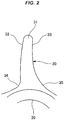
FIG. 2 is an enlarged view of a main part illustrating a blade of the impeller according to the first embodiment of the present invention. -
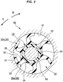
FIG. 3 is a cross-sectional view illustrating the mounting-state shape of the impeller according to the first embodiment of the present invention. -
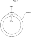
FIG. 4 is a front view of a tube provided in an impeller according to a second embodiment of the present invention. -
FIG. 5 is a cross-sectional view of a specific blade provided in the impeller according to the second embodiment of the present invention. -
FIG. 6 is a plan view illustrating a free-state shape of an impeller according to a first prior art. -
FIG. 7(a) is an enlarged view of a main part illustrating a blade of the impeller according to the first prior art, andFIG. 7(b) is a cross-sectional view illustrating a state where the blade of the impeller according to the first prior art is wrinkled. -
FIG. 8(a) is an enlarged view of a main part illustrating a blade of an impeller according to a second prior art, andFIG. 8(b) is a cross-sectional view illustrating a state where the blade of the impeller according to the second prior art is wrinkled. - Next, an
impeller 10 according to embodiments will be described in detail with reference to accompanying drawings. - The
impeller 10 according to the present embodiment is used for a pump device or the like. As illustrated inFIGS. 1 to 3 , theimpeller 10 is provided with anannular tube 20 fixed to arotary shaft 50 provided in ashaft hole 42 of ahousing 40 and a plurality ofblades 30 protruding toward an outer diameter direction from thetube 20. - The
tube 20 is made of a resin material. Thetube 20 is provided with aninsertion hole 21 through which therotary shaft 50 is inserted and anotch portion 22 provided at a part on the circumference of theinsertion hole 21 and fixing therotary shaft 50. - The
blade 30 is made of a rubber material such as chloroprene rubber having a hardness ofHs 50 to 70. As illustrated inFIGS. 1 to 3 , theblades 30 circumferentially equally protrude from thetube 20 toward the outer diameter direction, atip 31 is in slidable contact with an innerperipheral surface 41 of thehousing 40, and theblade 30 has a shape curved to a rotation-direction rear side B of therotary shaft 50 in a free state. Anextension surface 32 and acompression surface 33 are provided in the root of theblade 30. Theextension surface 32 is positioned on a rotation-direction front side A of therotary shaft 50 and has a circular arc shape in cross section. Thecompression surface 33 is positioned on the rotation-direction rear side B of therotary shaft 50 and has a circular arc shape in cross section as in the case of theextension surface 32. A curvature radius R2 of aroot 35 on thecompression surface 33 is set larger than a curvature radius R1 of aroot 34 on theextension surface 32. In other words, the curvature radius R2 of thecompression surface 33 is set larger than the curvature radius R1 of theextension surface 32. - It is preferable that the
impeller 10 in the present embodiment illustrated inFIG. 1 is manufactured with the following dimensions. The impeller of the present invention is not limited to the following dimensional ranges. - A radial length W of the
blade 30 is set to 20 to 30 mm. Accordingly, theimpeller 10 according to the embodiment is a large impeller in which the radial length W of theblade 30 is large. - It is preferable to set R1 to 0.1W to 0.4W with W representing the radial length of the
blade 30 and R1 representing the curvature radius of theroot 34 on theextension surface 32 in theblade 30. When W is 20 to 30 mm, R1 is preferably 2.5 to 10 mm and more preferably 3 to 6 mm. - It is preferable to set R2 to 0.5W to 1.2W with W representing the radial length of the
blade 30 and R2 representing the curvature radius of theroot 35 on thecompression surface 33 in theblade 30. When W is 20 to 30 mm, R2 is preferably 12 to 30 mm and more preferably 18 to 2 - It is preferable to set R3 to 0.8W to 1.8W with W representing the radial length of the
blade 30 and R3 representing the curvature radius of a radial midsection C on thecompression surface 33 in theblade 30. When W is 20 to 30 mm, R3 is preferably 20 to 45 mm and more preferably 28 to 32 mm. - It is preferable to set R4 to 1W to 5W with W representing the radial length of the
blade 30 and R4 representing the curvature radius of the radial midsection C on theextension surface 32 in theblade 30. When W is 20 to 30 mm, R4 is preferably 25 to 125 mm and more preferably 75 to 85 mm. - As for the
extension surface 32 near thetip 31 of theblade 30, it is preferable to set an inclination angle θ1 with respect to the diameter line of theimpeller 10 to 3 to 9 degrees. More preferably, the inclination angle θ1 is set to 6 to 8 degrees. - As for the
compression surface 33 near thetip 31 of theblade 30, it is preferable to set an inclination angle θ2 with respect to the diameter line of theimpeller 10 to 1 to 5 degrees. More preferably, the inclination angle θ2 is set to 1.5 to 3.5 degrees. - The
impeller 10 configured as described above is attached to therotary shaft 50 eccentric to the innerperipheral surface 41 of thehousing 40. By therotary shaft 50 rotating to the rotation-direction front side A, theblade 30 slides with the innerperipheral surface 41 of thehousing 40 and theblades 30 are sequentially bent toward the rotation-direction rear side B. By theblades 30 being bent, the space between ablade 30a and anadjacent blade 30b decreases. As a result, the pressure of the liquid in the space increases and the liquid is discharged to a discharge port (not illustrated). Further, once the space between theblade 30a and theadjacent blade 30b increases by theblade 30 exerting an elastic restoring force, the pressure of the liquid in the space decreases and the liquid is suctioned into a suction port (not illustrated). - As described above, in the
impeller 10 according to the present embodiment, a volume change is repeated in the space between theblade 30a and theadjacent blade 30b as therotary shaft 50 rotates. Accordingly, the liquid can be sequentially introduced from the right side to the left side inFIG. 3 . - As illustrated in
FIG. 2 , in theimpeller 10 according to the present embodiment, theblade 30 has a shape curved to the rotation-direction rear side B. Accordingly, theentire blade 30 smoothly bends as compared with theblade 530 according to the prior art, which is illustrated inFIGS. 7(a) and8(a) and has a linear shape in the free state. As a result, it is possible to improve the durability of theimpeller 10 by suppressing lopsided strain concentration and preventing theblade 30 from wrinkling. - In the
impeller 10 according to the present embodiment, the curvature radius R2 of theroot 35 on thecompression surface 33 in theblade 30 is set larger than the curvature radius R1 of theroot 34 on theextension surface 32 . Accordingly, theblade 30 is incapable of bending to the rotation-direction rear side B beyond a required range. As a result, it is possible to ensure a certain repulsive force with respect to thehousing 40 of theblade 30. - In the
impeller 10 according to the present embodiment, theextension surface 32 and thecompression surface 33 near thetip 31 of theblade 30 are inclined with respect to the diameter line of theimpeller 10, and thus wrinkling can be further prevented. - In the
impeller 10 according to the present embodiment, theblade 30 is curved in the free state, and thus theblade 30 can be easily assembled to therotary shaft 50 provided in thehousing 40. - The
impeller 10 according to the present embodiment achieves the above-described action and effect simply by means of a change in the shape of theblade 30. Accordingly, theimpeller 10 can be manufactured at the same cost as theimpeller 510 according to the prior art. - In the impeller of the present invention, strain reduction is achieved and wrinkling of the blade becomes less likely by the wall thickness of the blade being reduced.
- As illustrated in
FIG. 4 , in theimpeller 10 according to the first embodiment, thetube 20 may be abush 20A made of, for example, a resinous or metallic rigid material. A key groove 20Aa for rotation stopping with respect to therotary shaft 50 may be provided in one place on the circumference of the inner peripheral surface of the rigid material-basedbush 20A. At the position that circumferentially corresponds to the key groove 20Aa, a raised portion 20Ab as a circumferential part may be provided on the outer peripheral surface of the position so that the part where the key groove 20Aa is provided is reinforced. In this case, all of the outer diameter dimensions of the plurality ofblades 30 equally distributed on the outer peripheral side of thebush 20A are constant, and thus only aspecific blade 30A at the position that circumferentially corresponds to the key groove 20Aa and the raised portion 20Ab is formed so as to have a blade length shorter than the blade length of theother blades 30. - As for the
specific blade 30A, the rubber volume of theroot 35 on thecompression surface 33 becomes too large once the curvature radius of theroot 35 on thecompression surface 33 in thespecific blade 30A is formed larger than the curvature radius of theroot 34 on theextension surface 32 in thespecific blade 30A as in the first embodiment described above. Then, the boundary position between theroot 35 on thecompression surface 33 and a length-direction middle portion (radial midsection) 36 in thespecific blade 30A becomes a strain concentration portion and wrinkling may occur in the strain concentration portion. Even without the raised portion 20Ab being provided, the same can be said also in the case of a small impeller in which the radial length of eachblade 30 is as small as approximately 9 to 15 mm. - In this regard, the following shape is preferably adopted in a case where the length of the
specific blade 30A or theblade 30 is small. - In other words, preferable is manufacturing with the dimensions illustrated in an enlarged manner in
FIG. 5 . The impeller of the present invention is not limited to the following dimensional ranges. - A radial length W1 of the
specific blade 30A or theblade 30 is set to 9 to 15 mm as described above. - It is preferable to set R11 to 0.1W1 to 0.5W1 with W1 representing the radial length of the
specific blade 30A or theblade 30 and R11 representing the curvature radius of theroot 34 on theextension surface 32 in the specific blade 30Aor theblade 30. When W1 is 9 to 15 mm, R11 is preferably 1 to 5 mm. - It is preferable to set R12 to 0.1W1 to 0.5W1 with W1 representing the radial length of the
specific blade 30A or theblade 30 and R12 representing the curvature radius of theroot 35 on thecompression surface 33 in thespecific blade 30A or theblade 30. When W1 is 9 to 15 mm, R12 is preferably 1 to 5 mm. - It is preferable to set R13 to 0.5W1 to 1.0W1 with W1 representing the radial length of the
specific blade 30A or theblade 30 and R13 representing the curvature radius of the radial midsection on thecompression surface 33 in thespecific blade 30A or theblade 30. When W1 is 9 to 15 mm, R13 is preferably 5 to 10 mm. - It is preferable to set R14 to 2W1 to 6W1 with W1 representing the radial length of the
specific blade 30A or theblade 30 and R14 representing the curvature radius of the radial midsection on theextension surface 32 in thespecific blade 30A or theblade 30. When W1 is 9 to 15 mm, R14 is preferably 20 to 60 mm. - As for the
extension surface 32 near thetip 31 of theblade 30 or thespecific blade 30A, it is preferable to set the inclination angle θ1 with respect to the diameter line of theimpeller 10 to 4 to 9 degrees. More preferably, the inclination angle θ1 is set to 5 to 8 degrees. - As for the
compression surface 33 near thetip 31 of theblade 30 or thespecific blade 30A, it is preferable to set the inclination angle θ2 with respect to the diameter line of theimpeller 10 to 5 to 10 degrees. More preferably, the inclination angle θ2 is set to 7 to 10 degrees. - By each curvature dimension and inclination angle being set as described above, the strain concentration portion is disposed in the R of the length-direction
middle portion 36 on thecompression surface 33 , the R joint in the strain concentration portion disappears, the rubber volume of theroot 35 on thecompression surface 33 decreases, and thus wrinkling becomes unlikely. - Accordingly, even in a case where the length of the
specific blade 30A or theblade 30 is small, wrinkling attributable to strain concentration can be prevented as in theother blades 30 and it is possible to ensure a repulsive force with respect to thehousing 40 of thespecific blade 30A or theblade 30. - A plurality of the raised portions 20Ab may be provided on the circumference. The raised portion 20Ab may be provided at a position not corresponding to the key groove 20Aa.
-
- 10
- impeller
- 20
- tube
- 21
- insertion hole
- 22
- notch portion
- 30
- blade
- 30A
- specific blade
- 31
- tip
- 32
- extension surface
- 33
- compression surface
- 34, 35
- root
- 36
- length-direction middle portion
- C
- radial midsection
- W
- radial length
- 40
- housing
- 41
- inner peripheral surface
- 42
- shaft hole
- 50
- rotary shaft
- A
- rotation-direction front side
- B
- rotation-direction rear side
Claims (2)
- An impeller attached to a rotary shaft provided in an inner space of a housing, the impeller comprising:a tube fixed to the rotary shaft; anda blade protruding toward an outer diameter direction from the tube, a tip of the blade being in slidable contact with an inner peripheral surface of the housing,wherein the blade has a shape curved toward a rotation-direction rear side of the rotary shaft in a free state and includes an extension surface on a rotation-direction front side of the rotary shaft and a compression surface on the rotation-direction rear side of the rotary shaft, andwherein a curvature radius of a root on the compression surface in the blade is formed larger than a curvature radius of a root on the extension surface in the blade.
- An impeller attached to a rotary shaft provided in an inner space of a housing, the impeller comprising:a tube fixed to the rotary shaft; anda blade protruding toward an outer diameter direction from the tube, a tip of the blade being in slidable contact with an inner peripheral surface of the housing,wherein the blade has a shape curved toward a rotation-direction rear side of the rotary shaft in a free state and includes an extension surface on a rotation-direction front side of the rotary shaft and a compression surface on the rotation-direction rear side of the rotary shaft,wherein the blade has a radial length of 9 to 15 mm,wherein a relationship of R11=0.1W1 to 0.5W1 is satisfied with W1 representing the radial length of the blade and R11 representing a curvature radius of a root on the extension surface in the blade,wherein a relationship of R12=0.1W1 to 0.5W1 is satisfied with W1 representing the radial length of the blade and R12 representing a curvature radius of a root on the compression surface in the blade,wherein a relationship of R13=0.5W1 to 1.0W1 is satisfied with W1 representing the radial length of the blade and R13 representing a curvature radius of a radial midsection on the compression surface in the blade,wherein a relationship of R14=2W1 to 6W1 is satisfied with W1 representing the radial length of the blade and R14 representing a curvature radius of a radial midsection on the extension surface in the blade,wherein an inclination angle θ1 of the extension surface near the tip of the blade with respect to an impeller diameter line is set to 4 to 9 degrees, andwherein an inclination angle θ2 of the compression surface near the tip of the blade with respect to the impeller diameter line is set to 5 to 10 degrees.
Applications Claiming Priority (2)
| Application Number | Priority Date | Filing Date | Title |
|---|---|---|---|
| JP2016218154 | 2016-11-08 | ||
| PCT/JP2017/036254 WO2018088077A1 (en) | 2016-11-08 | 2017-10-05 | Impeller |
Publications (2)
| Publication Number | Publication Date |
|---|---|
| EP3540227A1 true EP3540227A1 (en) | 2019-09-18 |
| EP3540227A4 EP3540227A4 (en) | 2019-09-18 |
Family
ID=62109162
Family Applications (1)
| Application Number | Title | Priority Date | Filing Date |
|---|---|---|---|
| EP17869413.9A Withdrawn EP3540227A4 (en) | 2016-11-08 | 2017-10-05 | PROPELLER |
Country Status (5)
| Country | Link |
|---|---|
| US (1) | US11053937B2 (en) |
| EP (1) | EP3540227A4 (en) |
| JP (1) | JP6445225B2 (en) |
| CN (1) | CN109804163B (en) |
| WO (1) | WO2018088077A1 (en) |
Family Cites Families (14)
| Publication number | Priority date | Publication date | Assignee | Title |
|---|---|---|---|---|
| US2466440A (en) * | 1948-07-29 | 1949-04-05 | Kiekhaefer Elmer Carl | Impeller for rotary pumps |
| DE808914C (en) | 1948-10-02 | 1951-07-19 | Kloeckner Humboldt Deutz Ag | Positive displacement pump |
| US2772637A (en) | 1952-03-20 | 1956-12-04 | Jabsco Pump Co | Impeller pump |
| US3053190A (en) * | 1961-04-10 | 1962-09-11 | Minnesota Rubber Co | Rotary vane type positive displacement pump |
| JPS48104107A (en) * | 1972-04-14 | 1973-12-27 | ||
| JPS49142604U (en) * | 1973-04-02 | 1974-12-09 | ||
| JPS5632637Y2 (en) * | 1975-12-03 | 1981-08-03 | ||
| JPS6310281U (en) * | 1986-07-07 | 1988-01-23 | ||
| US4718837A (en) * | 1986-08-18 | 1988-01-12 | Frazzell Michael E | Marine drive water pump impeller |
| JPS63186981A (en) * | 1987-01-29 | 1988-08-02 | Anretsuto:Kk | Flexible pump |
| JPH0510799U (en) | 1991-07-16 | 1993-02-12 | エヌオーケー株式会社 | Bush for impeller |
| JPH05306687A (en) | 1992-04-30 | 1993-11-19 | Suzuki Motor Corp | Rotary liquid pump |
| ITBO20090766A1 (en) * | 2009-11-25 | 2011-05-26 | Roberto Manzini | ROTOR FOR PUMPS |
| US9599120B2 (en) * | 2012-08-24 | 2017-03-21 | Asmo Co., Ltd. | Impeller for centrifugal pump and centrifugal pump of vehicle washer device |
-
2017
- 2017-10-05 EP EP17869413.9A patent/EP3540227A4/en not_active Withdrawn
- 2017-10-05 JP JP2018545521A patent/JP6445225B2/en active Active
- 2017-10-05 WO PCT/JP2017/036254 patent/WO2018088077A1/en not_active Ceased
- 2017-10-05 CN CN201780059569.7A patent/CN109804163B/en active Active
- 2017-10-05 US US16/342,896 patent/US11053937B2/en active Active
Also Published As
| Publication number | Publication date |
|---|---|
| US20190242379A1 (en) | 2019-08-08 |
| JPWO2018088077A1 (en) | 2018-11-29 |
| CN109804163B (en) | 2020-05-05 |
| CN109804163A (en) | 2019-05-24 |
| JP6445225B2 (en) | 2018-12-26 |
| WO2018088077A1 (en) | 2018-05-17 |
| EP3540227A4 (en) | 2019-09-18 |
| US11053937B2 (en) | 2021-07-06 |
Similar Documents
| Publication | Publication Date | Title |
|---|---|---|
| JP3875824B2 (en) | Lip type seal | |
| US9874219B2 (en) | Impeller and fluid machine | |
| JP5710053B2 (en) | Sealing device | |
| EP2103782B1 (en) | Blade structure for gas turbine | |
| EP2123916B1 (en) | Compressor housing | |
| EP1944534B1 (en) | Rotation shaft seal | |
| JP2008281192A (en) | Seal ring | |
| EP3012495B1 (en) | Use of hermetic seal device | |
| CN108930656A (en) | Vacuum pumping hardware, vacuum pump and vacuum valve | |
| US11053937B2 (en) | Curved flexible impeller | |
| JPWO2017163992A1 (en) | Sealing device | |
| CN104583614B (en) | Snap ring | |
| CN112771281B (en) | Bearing device | |
| US10670031B2 (en) | Compressor | |
| EP3312428B1 (en) | Inducer and pump | |
| JP2003097723A (en) | Rotation shaft seal | |
| CN107250487B (en) | Seals for turbomachines, sheets for turbomachines and seals | |
| EP3816454A1 (en) | Blade and axial flow impeller using same | |
| CN215410188U (en) | Lip type shaft seal device | |
| CN104948740A (en) | Rotation shaft seal | |
| JP2002115762A (en) | Sealing device | |
| US11339796B2 (en) | Fan | |
| JP2021167641A (en) | Sealing device | |
| US20200224678A1 (en) | Fan and motor thereof | |
| JP3219517U (en) | Lip seal device |
Legal Events
| Date | Code | Title | Description |
|---|---|---|---|
| STAA | Information on the status of an ep patent application or granted ep patent |
Free format text: STATUS: THE INTERNATIONAL PUBLICATION HAS BEEN MADE |
|
| PUAI | Public reference made under article 153(3) epc to a published international application that has entered the european phase |
Free format text: ORIGINAL CODE: 0009012 |
|
| STAA | Information on the status of an ep patent application or granted ep patent |
Free format text: STATUS: REQUEST FOR EXAMINATION WAS MADE |
|
| 17P | Request for examination filed |
Effective date: 20190423 |
|
| A4 | Supplementary search report drawn up and despatched |
Effective date: 20190813 |
|
| AK | Designated contracting states |
Kind code of ref document: A1 Designated state(s): AL AT BE BG CH CY CZ DE DK EE ES FI FR GB GR HR HU IE IS IT LI LT LU LV MC MK MT NL NO PL PT RO RS SE SI SK SM TR |
|
| AX | Request for extension of the european patent |
Extension state: BA ME |
|
| DAV | Request for validation of the european patent (deleted) | ||
| DAX | Request for extension of the european patent (deleted) | ||
| STAA | Information on the status of an ep patent application or granted ep patent |
Free format text: STATUS: EXAMINATION IS IN PROGRESS |
|
| 17Q | First examination report despatched |
Effective date: 20200708 |
|
| GRAP | Despatch of communication of intention to grant a patent |
Free format text: ORIGINAL CODE: EPIDOSNIGR1 |
|
| STAA | Information on the status of an ep patent application or granted ep patent |
Free format text: STATUS: GRANT OF PATENT IS INTENDED |
|
| INTG | Intention to grant announced |
Effective date: 20220706 |
|
| STAA | Information on the status of an ep patent application or granted ep patent |
Free format text: STATUS: THE APPLICATION IS DEEMED TO BE WITHDRAWN |
|
| 18D | Application deemed to be withdrawn |
Effective date: 20221117 |