EP3540196B1 - Systeme und verfahren für kraftstoffbasiertes wärmemanagement - Google Patents
Systeme und verfahren für kraftstoffbasiertes wärmemanagement Download PDFInfo
- Publication number
- EP3540196B1 EP3540196B1 EP19161301.7A EP19161301A EP3540196B1 EP 3540196 B1 EP3540196 B1 EP 3540196B1 EP 19161301 A EP19161301 A EP 19161301A EP 3540196 B1 EP3540196 B1 EP 3540196B1
- Authority
- EP
- European Patent Office
- Prior art keywords
- fuel
- controller
- fluid
- temperature
- heat exchanger
- Prior art date
- Legal status (The legal status is an assumption and is not a legal conclusion. Google has not performed a legal analysis and makes no representation as to the accuracy of the status listed.)
- Active
Links
Images




Classifications
-
- F—MECHANICAL ENGINEERING; LIGHTING; HEATING; WEAPONS; BLASTING
- F02—COMBUSTION ENGINES; HOT-GAS OR COMBUSTION-PRODUCT ENGINE PLANTS
- F02C—GAS-TURBINE PLANTS; AIR INTAKES FOR JET-PROPULSION PLANTS; CONTROLLING FUEL SUPPLY IN AIR-BREATHING JET-PROPULSION PLANTS
- F02C9/00—Controlling gas-turbine plants; Controlling fuel supply in air- breathing jet-propulsion plants
- F02C9/26—Control of fuel supply
- F02C9/28—Regulating systems responsive to plant or ambient parameters, e.g. temperature, pressure, rotor speed
-
- B—PERFORMING OPERATIONS; TRANSPORTING
- B64—AIRCRAFT; AVIATION; COSMONAUTICS
- B64D—EQUIPMENT FOR FITTING IN OR TO AIRCRAFT; FLIGHT SUITS; PARACHUTES; ARRANGEMENT OR MOUNTING OF POWER PLANTS OR PROPULSION TRANSMISSIONS IN AIRCRAFT
- B64D37/00—Arrangements in connection with fuel supply for power plant
- B64D37/32—Safety measures not otherwise provided for, e.g. preventing explosive conditions
-
- F—MECHANICAL ENGINEERING; LIGHTING; HEATING; WEAPONS; BLASTING
- F01—MACHINES OR ENGINES IN GENERAL; ENGINE PLANTS IN GENERAL; STEAM ENGINES
- F01P—COOLING OF MACHINES OR ENGINES IN GENERAL; COOLING OF INTERNAL-COMBUSTION ENGINES
- F01P3/00—Liquid cooling
-
- F—MECHANICAL ENGINEERING; LIGHTING; HEATING; WEAPONS; BLASTING
- F02—COMBUSTION ENGINES; HOT-GAS OR COMBUSTION-PRODUCT ENGINE PLANTS
- F02C—GAS-TURBINE PLANTS; AIR INTAKES FOR JET-PROPULSION PLANTS; CONTROLLING FUEL SUPPLY IN AIR-BREATHING JET-PROPULSION PLANTS
- F02C7/00—Features, components parts, details or accessories, not provided for in, or of interest apart form groups F02C1/00 - F02C6/00; Air intakes for jet-propulsion plants
- F02C7/12—Cooling of plants
- F02C7/14—Cooling of plants of fluids in the plant, e.g. lubricant or fuel
-
- F—MECHANICAL ENGINEERING; LIGHTING; HEATING; WEAPONS; BLASTING
- F02—COMBUSTION ENGINES; HOT-GAS OR COMBUSTION-PRODUCT ENGINE PLANTS
- F02C—GAS-TURBINE PLANTS; AIR INTAKES FOR JET-PROPULSION PLANTS; CONTROLLING FUEL SUPPLY IN AIR-BREATHING JET-PROPULSION PLANTS
- F02C7/00—Features, components parts, details or accessories, not provided for in, or of interest apart form groups F02C1/00 - F02C6/00; Air intakes for jet-propulsion plants
- F02C7/22—Fuel supply systems
- F02C7/224—Heating fuel before feeding to the burner
-
- F—MECHANICAL ENGINEERING; LIGHTING; HEATING; WEAPONS; BLASTING
- F02—COMBUSTION ENGINES; HOT-GAS OR COMBUSTION-PRODUCT ENGINE PLANTS
- F02C—GAS-TURBINE PLANTS; AIR INTAKES FOR JET-PROPULSION PLANTS; CONTROLLING FUEL SUPPLY IN AIR-BREATHING JET-PROPULSION PLANTS
- F02C7/00—Features, components parts, details or accessories, not provided for in, or of interest apart form groups F02C1/00 - F02C6/00; Air intakes for jet-propulsion plants
- F02C7/22—Fuel supply systems
- F02C7/232—Fuel valves; Draining valves or systems
-
- F—MECHANICAL ENGINEERING; LIGHTING; HEATING; WEAPONS; BLASTING
- F01—MACHINES OR ENGINES IN GENERAL; ENGINE PLANTS IN GENERAL; STEAM ENGINES
- F01P—COOLING OF MACHINES OR ENGINES IN GENERAL; COOLING OF INTERNAL-COMBUSTION ENGINES
- F01P3/00—Liquid cooling
- F01P2003/005—Liquid cooling the liquid being fuel
-
- F—MECHANICAL ENGINEERING; LIGHTING; HEATING; WEAPONS; BLASTING
- F05—INDEXING SCHEMES RELATING TO ENGINES OR PUMPS IN VARIOUS SUBCLASSES OF CLASSES F01-F04
- F05D—INDEXING SCHEME FOR ASPECTS RELATING TO NON-POSITIVE-DISPLACEMENT MACHINES OR ENGINES, GAS-TURBINES OR JET-PROPULSION PLANTS
- F05D2220/00—Application
- F05D2220/30—Application in turbines
- F05D2220/32—Application in turbines in gas turbines
- F05D2220/323—Application in turbines in gas turbines for aircraft propulsion, e.g. jet engines
-
- F—MECHANICAL ENGINEERING; LIGHTING; HEATING; WEAPONS; BLASTING
- F05—INDEXING SCHEMES RELATING TO ENGINES OR PUMPS IN VARIOUS SUBCLASSES OF CLASSES F01-F04
- F05D—INDEXING SCHEME FOR ASPECTS RELATING TO NON-POSITIVE-DISPLACEMENT MACHINES OR ENGINES, GAS-TURBINES OR JET-PROPULSION PLANTS
- F05D2260/00—Function
- F05D2260/20—Heat transfer, e.g. cooling
-
- F—MECHANICAL ENGINEERING; LIGHTING; HEATING; WEAPONS; BLASTING
- F05—INDEXING SCHEMES RELATING TO ENGINES OR PUMPS IN VARIOUS SUBCLASSES OF CLASSES F01-F04
- F05D—INDEXING SCHEME FOR ASPECTS RELATING TO NON-POSITIVE-DISPLACEMENT MACHINES OR ENGINES, GAS-TURBINES OR JET-PROPULSION PLANTS
- F05D2260/00—Function
- F05D2260/20—Heat transfer, e.g. cooling
- F05D2260/213—Heat transfer, e.g. cooling by the provision of a heat exchanger within the cooling circuit
-
- Y—GENERAL TAGGING OF NEW TECHNOLOGICAL DEVELOPMENTS; GENERAL TAGGING OF CROSS-SECTIONAL TECHNOLOGIES SPANNING OVER SEVERAL SECTIONS OF THE IPC; TECHNICAL SUBJECTS COVERED BY FORMER USPC CROSS-REFERENCE ART COLLECTIONS [XRACs] AND DIGESTS
- Y02—TECHNOLOGIES OR APPLICATIONS FOR MITIGATION OR ADAPTATION AGAINST CLIMATE CHANGE
- Y02T—CLIMATE CHANGE MITIGATION TECHNOLOGIES RELATED TO TRANSPORTATION
- Y02T50/00—Aeronautics or air transport
- Y02T50/60—Efficient propulsion technologies, e.g. for aircraft
Definitions
- the present disclosure relates generally to thermal management systems, and more specifically, to systems and methods for fuel-based thermal management of a gas turbine engine.
- a thermal management system in a gas turbine engine may maintain operable temperatures for fuel, oil, and other fluid communicated through the engine.
- Thermal management systems may employ fuel on board an aircraft as a heat sink to increase operational efficiency of the aircraft.
- thermal loads increase due to enhanced electrical architecture in aircraft, a higher thermal load is imposed on the fuel.
- Conventional methods for accommodating increased thermal loads tend to achieve greater heat transfer by increasing the number heat exchangers or the size of heat exchangers within the system. Increasing the number or size of the heat exchangers can impose additional weight, space, and/or complexity to the airframe.
- US 2014/090395 A1 discloses a cooling system for a gas turbine engine, the system comprising a fuel air heat exchanger comprising a fuel passage in thermal contact with an engine cooling air passage.
- US 2016/332743 A1 discloses a method of protecting fuel hardware in a gas turbine engine.
- the method may include determining a current altitude of the aircraft and controlling a temperature of fuel for the gas turbine engine based at least in part on the current altitude.
- a fuel-based thermal management system as claimed in claim 1 is provided.
- modulating the flow of the fluid to the heat exchanger based on the updated dissolved oxygen concentration in the fuel may comprise determining a fuel coking temperature based on the updated dissolved oxygen concentration, comparing the fuel coking temperature to the first fuel temperature, and determining whether a thermal load from the fluid can be deposited into the fuel based on the comparing of the fuel coking temperature to the first fuel temperature.
- modulating the flow of the fluid to the heat exchanger based on the updated dissolved oxygen concentration in the fuel may further comprise depositing the thermal load from the fluid into the fuel, receiving a second fuel temperature from a second temperature sensor downstream of the heat exchanger, comparing the fuel coking temperature to the second fuel temperature, and determining whether to actuate the valve based on the comparing of the fuel coking temperature to the second fuel temperature.
- depositing the thermal load from the fluid into the fuel may comprise actuating the valve to an open position.
- modulating the flow of the fluid to the heat exchanger based on the dissolved oxygen concentration in the fuel may further comprise actuating the valve to a closed position if the second fuel temperature is greater than the fuel coking temperature.
- a fluid output from the heat exchanger may be directed to a component of the gas turbine engine.
- the fluid may comprise oil or air.
- the dissolved oxygen concentration measurement output from the oxygen sensor corresponds to a pre-flight concentration of dissolved oxygen in the fuel.
- determining whether the thermal load from the fluid can be deposited into the fuel may comprise determining a fuel coking temperature based on the updated dissolved oxygen concentration, and comparing the fuel coking temperature to the first fuel temperature.
- modulating the flow of the fluid to the heat exchanger may further comprise depositing the thermal load from the fluid into the fuel, receiving a second fuel temperature from a second fuel temperature sensor downstream of the heat exchanger, comparing the fuel coking temperature to the second fuel temperature, and determining whether to adjust a flow rate of the fluid to the heat exchanger based on the comparing of the fuel coking temperature to the second fuel temperature.
- depositing the thermal load from the fluid into the fuel may comprise actuating a valve fluidly coupled between a source of the fluid and the heat exchanger.
- modulating the flow of the fluid to the heat exchanger may further comprise decreasing the flow rate of the fluid if the second fuel temperature is greater than the fuel coking temperature.
- decreasing the flow rate of the fluid may comprise actuating a valve fluidly coupled between a source of the fluid and the heat exchanger.
- the fluid may comprise at least one of oil, air, lubricating fluid, fuel, or hydraulic fluid. In various embodiments, the fluid may be output from a component of the gas turbine engine.
- any of the method or process descriptions may be executed in any order and are not necessarily limited to the order presented.
- any reference to singular includes plural embodiments, and any reference to more than one component or step may include a singular embodiment or step.
- any reference to attached, fixed, connected or the like may include permanent, removable, temporary, partial, full and/or any other possible attachment option.
- any reference to without contact (or similar phrases) may also include reduced contact or minimal contact.
- Computer-based system program instructions and/or processor instructions may be loaded onto a tangible, non-transitory computer readable medium having instructions stored thereon that, in response to execution by a processor, cause the processor to perform various operations.
- the term "non-transitory” is to be understood to remove only propagating transitory signals per se from the claim scope and does not relinquish rights to all standard computer-readable media that are not only propagating transitory signals per se.
- a fuel-based thermal management system which utilizes fuel temperature, flight cycle time, and altitude and/or ambient pressure to determine a threshold fuel temperature for a gas turbine engine and to determine whether a thermal energy load may be deposited into the fuel.
- the fuel-based thermal management system may increase and/or maximize thermal energy deposited into fuel, while maintaining the fuel below a temperature associated with fuel coking, fuel lacquering, or other deposit formation due to thermal degradation to increase or optimize overall thermodynamic cycle efficiency.
- Gas turbine engine 20 may generally comprise a compressor section 22 where air is pressurized, a combustor 24 downstream of the compressor section 22 which mixes and ignites the compressed air with fuel and thereby generates hot combustion gases, a turbine section 26 downstream of the combustor 24 for extracting power from the hot combustion gases.
- compressor section 22, combustor 24, and turbine section 26 generate heat, which may be carried by fluids communicated throughout gas turbine engine 20.
- fluids communicated throughout gas turbine engine 20 For example, fuel, oil, air, lubricating fluids, hydraulic fluids, and the like may be circulated throughout gas turbine engine 20 and may carry a portion of the heat generated during operation.
- fuel injected into combustor 24 may be employed as a heat sink to remove (i.e., absorb) thermal loads from one or more fluid(s) communicated through gas turbine engine 20.
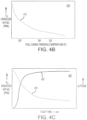
- FIG. 4B illustrates a graph 410 comparing fuel-dissolved O2 concentration with fuel coking threshold temperature.
- Line 412 illustrates that as fuel-dissolved O2 concentration decreases the fuel coking threshold temperature (i.e., the temperature at which the fuel degradation occurs) increase.
- an exemplary graphical representation 400 of ambient air O2 concentration over a flight profile and altitude over the flight profile is illustrated, according to various embodiments.
- line 402 illustrates ambient air O2 concentration the flight profile and line 404 illustrates altitude of the aircraft over the flight profile.
- the fuel injected into gas turbine engine 20 may be stored in a fuel tank that is vented (i.e., opened) such that fuel within the tank is exposed to ambient air.
- the fuel being exposed to ambient air may allow the ambient air conditions to affect the conditions of fuel in fuel tank. For example, the decreased partial pressure of O2 at higher altitudes may result in less ambient O2 being available to be dissolved into the fuel.
- FIG. 4C illustrates a graph 420 comparing fuel-dissolved O2 concentration 424 and aircraft altitude 422, as a function of flight time. Line 424 illustrates that as flight time (and aircraft altitude 422) increases the fuel-dissolved O2 concentration decreases.
- the combined effects of lower ambient air pressure (and, hence lower O2 partial pressure) and the increased degassing of O2 from the liquid fuel may result in a lower O2 content in the liquid fuel.
- the reduced O2 concentration within the fuel may allow the fuel to absorb more heat before it can reach its thermal degradation limits.
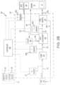
- Fuel-based thermal management system 200 may comprise fuel-fluid heat exchange system 202.
- Fuel-fluid heat exchange system 202 receives a fluid 250 output from a heat source 208.
- heat source 208 may comprise one or more components of gas turbine engine 20.
- Fluid 250 may comprise oil, air, lubricating fluid, fuel, hydraulic fluid, or any other aircraft or engine fluid.
- Fuel-fluid heat exchange system 202 further receives fuel 230 output from a fuel tank 232.
- Fuel-fluid heat exchange system 202 may be configured to exchange thermal energy (i.e., heat) between fluid 250 and fuel 230.
- thermal energy is transferred from fluid 250 to fuel 230 within fuel-fluid heat exchange system 202, such that a temperature of the fluid 250 input into fuel-fluid heat exchange system 202 is greater than the temperature of the fluid 250 output from fuel-fluid heat exchange system 202, and a temperature of the fuel 230 input into fuel-fluid heat exchange system 202 is less than the temperature of the fuel 230 output from fuel-fluid heat exchange system 202.
- Cooled fluid 250 i.e., the fluid output from fuel-fluid heat exchange system 202
- cooled fluid 250 may be used to cool one or more components of gas turbine engine 20.
- cooled fluid 250 may directed to, and may cool, an aircraft component other than gas turbine engine 20.
- Fuel-fluid heat exchange system 202 may be in communication with a controller 206.
- controller 206 may comprise a full authority digital engine control (FADEC) system.
- Controller 206 may comprise one or more processors configured to implement various logical operations in response to execution of instructions, for example, instructions stored on a non-transitory, tangible, computer-readable medium.
- the one or more processors can be a general purpose processor, a microprocessor, a microcontroller, a digital signal processor (DSP), an application specific integrated circuit (ASIC), a field programmable gate array (FPGA) or other programmable logic device, discrete gate or transistor logic, discrete hardware components, or any combination thereof.
- Controller 206 may include a memory 210.
- Memory 210 may store executable instructions and data to implement control logic of controller 206.
- Memory 210 may comprise a tangible, non-transitory storage medium and may store data used, for example, for trending and prognosis purposes.
- Controller 206 may be in logical and/or electronic communication with one or more components of fuel-based thermal management system 200.
- controller 206 may receive data output from fuel-fluid heat exchange system 202, gas turbine engine 20, heat source 208, fuel tank 232, and/or an avionics unit 212.
- Controller 206 may receive data correlating to various engine or aircraft operating conditions, such as, for example, altitude, ambient air temperature, ambient air pressure, dissolved O2 fuel concentration, time in flight cycle, temperature of fuel being input into heat exchanger, temperature of fuel being output from heat exchanger, temperature of the fuel in the fuel tank, speed of the aircraft, Mach number, rotational speed of one or more components of gas turbine engine 20, or any other operating information.
- Controller 206 may interpret data received from fuel-fluid heat exchange system 202, gas turbine engine 20, heat source 208, fuel tank 232, and/or an avionics unit 212 to determine a real-time dissolved O2 concentration within fuel 230 and the threshold fuel coking temperature associated with the dissolved O2 concentration.
- Fuel-fluid heat exchange system 202 may include a heat exchanger 252.
- Heat exchanger 252 is configured to thermally couple the fluid 250 output from heat source 208 and the fuel 230 output from fuel tank 232.
- a valve 254 (e.g., a flow control valve) may be located upstream of heat exchanger 252.
- Valve 254 may be located between, and fluidly coupled to, heat source 208 and heat exchanger 252 such that fluid 250 flows from an output of heat source 208 to an input of valve 254, and from an output of valve 254 to an input of heat exchanger 252.
- Valve 254 may be configured to regulate a flow rate of fluid 250 to heat exchanger 252.
- Controller 206 may be in operable communication with valve 254. Controller may cause an actuation of valve 254 to modulate and/or adjust a flow rate of fluid 250 to heat exchanger 252.
- a fuel pump 234, located between heat source 208 and fuel tank 232, may control the flow of fuel 230.
- Fuel 230 output from heat exchanger 252 may flow to a fuel control valve 270.
- Fuel control valve 270 may be configured to regulate the flow of fuel 230 to gas turbine engine 20, for example, to combustor 24.
- fuel control valve 270 may be configured to direct a first portion 230a of the fuel 230 output from heat exchanger 252 to flow to gas turbine engine 20 and to direct a second portion 230b of the fuel back into fuel tank 232.
- the O2-rich ullage of fuel tank 232 may be inerted by the a fuel tank inerting system at a determined rate such that fuel tank 232 remains inert during flight.
- the O2 is evolved out fuel 230 and accepted by the N2-rich environment due to the inerting process. Additional fuel agitation due to operation of fuel pump 234 may further enhance the degassing of O2 out of fuel 230 within fuel tank 232.
- Controller 206 receives data output from one or more sensor(s) within fuel-fluid heat exchange system 202, gas turbine engine 20, heat source 208, fuel tank 232, and/or avionics unit 212. Controller 206 receives and interprets temperature data from a fluid temperature sensor 260a. The data output from fluid temperature sensor 260a may correspond to the temperature of fluid 250 output from heat source 208. Controller receives and interprets temperature data from a fuel temperature sensor 260b upstream of heat exchanger 252. The data output from fuel temperature sensor 260b corresponds to the temperature of fuel 230 upstream of heat exchanger 252. Stated differently, the data output from fuel temperature sensor 260b may correspond to the temperature of fuel 230 output from fuel tank 232 and/or from fuel pump 234.
- Controller 206 may receive and interpret temperature data from a fuel temperature sensor 260c downstream of heat exchanger 252.
- the data output from fuel temperature sensor 260c may correspond to the temperature of fuel 230 downstream of, and/or output from, heat exchanger 252.
- Controller 206 may receive and interpret altitude data from an altitude sensor 266.
- altitude sensor 266 may be included in avionics unit 212.
- Controller 206 may receive and interpret ambient pressure data from a pressure sensor 262.
- pressure sensor 262 may be may be included in avionics unit 212.
- Controller 206 may also receive and interpret flight cycle time (e.g., minutes since take-off) from avionics unit 212.
- Controller 206 may receive and interpret dissolved O2 concentration data from an O2 sensor 264 in communication (e.g., fluid communication) with fuel 230.
- O2 sensor 264 may be located between fuel tank 232 and fuel pump 234.
- O2 sensor 264 may be located in fuel tank 232.
- Controller 206 may receive data from O2 sensor 264 corresponding to the pre-flight concentration of dissolved O2 in fuel 230 (e.g., measured when fuel 230 is loaded into fuel tank 232). Controller 206 may also receive in-flight dissolved O2 concentration data from O2 sensor 264 (e.g., continuously during flight).
- controller 206 may use some or all the sensor and/or avionics data to determine a real-time dissolved O2 concentration within fuel 230, the threshold fuel coking temperature associated with the dissolved O2 concentration, and/or the amount of thermal load fuel 230 can absorb without exceeding a threshold fuel coking temperature.
- Method 300 may comprise determining a temperature of a fluid output from a heat source (step 302), estimating a real-time dissolved O2 concentration within the fuel (step 304), and modulating a flow of the fluid to a heat exchanger based on the real-time dissolved O2 concentration (step 306).
- step 302 may comprise controller 206 receiving a fluid 250 temperature measurement from, for example, fluid temperature sensor 260a (step 310) and determining whether excess heat is available for deposition into fuel 230 (step 312). Stated differently, controller 206 may determine whether the temperature of fluid 250 is greater than a predetermined temperature threshold.
- the predetermined temperature threshold may vary based on flight cycle time. For example, the predetermined temperature threshold may decrease as time since take-off increases.
- controller 206 may compare the temperature of fluid 250 to a first predetermined temperature threshold during a flight cycle time of, for example, 0 minutes after take-off to 15 minutes after take-off, and may compare the temperature of fluid 250 to a second predetermined temperature threshold during a flight cycle time of, for example, 15 minutes after take-off to 15 minutes before landing. If controller 206 determines the temperature of fluid 250 is not greater than the predetermined temperature threshold, controller 206 returns to step 310. If controller 206 determines the temperature of fluid 250 is greater than or equal to the predetermined temperature threshold, controller estimates the dissolved O2 concentration of fuel 230 (step 304).
- step 304 comprises controller 206 receiving a first fuel temperature from, for example, fuel temperature sensor 260b (step 314), a flight cycle time (e.g., minutes since take-off data) from avionics unit 212 (step 316), and at least one of an altitude measurement from, for example, altitude sensor 266 or an ambient pressure measurement from, for example, pressure sensor 262 (step 318). Controller 206 estimates the dissolved O2 concentration using the first fuel temperature, flight cycle time, and altitude and/or pressure measurement(s).
- a flight cycle time e.g., minutes since take-off data
- step 304 further includes receiving a dissolved O2 concentration measurement from O2 sensor 264 and using the first fuel temperature, flight cycle time, and altitude and/or pressure measurement(s) to update or correct the dissolved O2 concentration measurement received from O2 sensor 264.
- a temperature of fuel tank 232 can also affect the degassing of O2 from fuel 230.
- O2 will degas from fuel 230 at a faster rate in a hotter fuel environment.
- the O2 dissolved in the fuel in a fuel tank of an aircraft taking off at first temperature will degas faster than O2 in a comparable amount of fuel in a comparable fuel tank of an aircraft taking off at second temperature that is less than first temperature.
- controller 206 may receive data related to the ambient air temperature and/or the fuel tank 232 temperature at take-off, and may use these data (along with flight cycle time, ambient pressure, etc.) to estimate the real-time O2 concentration in the fuel. After estimating the real-time O2 concentration, controller may modulate the flow of fluid 250 to heat exchanger 252 based on the real-time O2 concentration (step 306).
- step 306 may comprise controller 206 determining whether fuel 230 can absorb additional heat without exceeding the fuel coking temperature associated with the estimated O2 concentration (step 320).
- step 320 comprises controller 206 determining a fuel coking temperature based on the dissolved O2 concentration of fuel 230 (step 322), controller 206 comparing the fuel coking temperature to the temperature of fuel 230 (e.g., to the first fuel temperature output from fuel temperature sensor 260b) (step 324), and controller 206 determining whether a thermal load from fluid 250 can be deposited into fuel 230 based on the comparison of the fuel coking temperature to the temperature of fuel 230 (step 326).
- controller 206 determines fuel 230 cannot absorb a thermal load from fluid 250 without exceeding the fuel coking temperature
- controller 206 returns to step 320 until controller 206 determines fuel 230 can absorb additional heat without exceeding the fuel coking temperature.
- controller 206 determines that the temperature of fuel 230 is greater than the fuel coking temperature or is within a predetermined number of degrees from the fuel coking temperature
- controller actuates valve 254 to prevent or reduce a flow of fluid 250 to heat exchanger 252.
- controller 206 determines fuel 230 can absorb heat from fluid 250
- controller 206 causes heat from fluid 250 to be deposited in fuel 230 (step 330).
- step 330 may comprise controller 206 actuating valve 254.
- controller 206 may send a signal that causes valve 254 to actuate to an open position.
- step 306 may further include controller 206 receiving a second fuel temperature from, for example, fuel temperature sensor 260c, and comparing the fuel coking temperature to the second fuel temperature (step 332). Controller 206 may determine whether to actuate valve 254 based on the comparison of the fuel coking temperature to the second fuel temperature. If controller 206 determines that the second fuel temperature is greater than the fuel coking temperature, controller 206 may actuate valve 254 to a closed position that prevents or reduces the flow of fluid 250 to heat exchanger 252. (step 334).
- Fuel-based thermal management system 200 and method 300 may provide increased dissolved O2 concentration accuracy by being fully integrated with the aircraft on-board computers for receiving real-time flight data.
- Increasing the dissolved O2 concentration accuracy may extend the fuel's heat sink capabilities without adding additional heat exchangers or other hardware and/or without increasing the size of the heat exchanger(s).
- Increasing the accuracy of the real-time detection of dissolved O2 concentration reduces potential unwanted occurrences of damage to fuel system components by reducing their exposure to fuel that is above the fuel's coking temperature for extended periods of time.
- references to "various embodiments”, “one embodiment”, “an embodiment”, “an example embodiment”, etc. indicate that the embodiment described may include a particular feature, structure, or characteristic, but every embodiment may not necessarily include the particular feature, structure, or characteristic. Moreover, such phrases are not necessarily referring to the same embodiment. Further, when a particular feature, structure, or characteristic is described in connection with an embodiment, it is submitted that it is within the knowledge of one skilled in the art to affect such feature, structure, or characteristic in connection with other embodiments whether or not explicitly described. After reading the description, it will be apparent to one skilled in the relevant art(s) how to implement the disclosure in alternative embodiments.
Landscapes
- Engineering & Computer Science (AREA)
- Chemical & Material Sciences (AREA)
- Combustion & Propulsion (AREA)
- Mechanical Engineering (AREA)
- General Engineering & Computer Science (AREA)
- Aviation & Aerospace Engineering (AREA)
- Engine Equipment That Uses Special Cycles (AREA)
Claims (12)
- Kraftstoffbasiertes Wärmemanagementsystem (200) für ein Gasturbinentriebwerk, umfassend:
ein Kraftstoff-Fluid-Wärmeaustauschsystem (202), das Folgendes umfasst:einen Wärmetauscher (252), der dazu konfiguriert ist, ein von einer Wärmequelle (208) empfangenes Fluid (250) und einen von einer Kraftstoffquelle (232) empfangenen Kraftstoff (230) thermisch zu koppeln, undein Ventil (254), das dazu konfiguriert ist, eine Strömung des Fluids zu dem Wärmetauscher zu regulieren;eine Steuerung (206) in Wirkverbindung mit dem Ventil; undeinen physischen, nicht transitorischen Speicher, der dazu konfiguriert ist, mit der Steuerung zu kommunizieren, wobei der physische, nicht transitorische Speicher darauf gespeicherte Anweisungen aufweist, die als Reaktion auf eine Ausführung durch die Steuerung die Steuerung dazu veranlassen, Vorgänge durchzuführen, die Folgendes umfassen:Bestimmen, ob eine Temperatur des Fluids über einem vorbestimmten Fluidtemperaturschwellenwert liegt, durch die Steuerung,Empfangen einer Messung der Konzentration von gelöstem Sauerstoff durch die Steuerung von einem Sauerstoffsensor (264), der mit dem Kraftstoff in Verbindung steht;Empfangen einer ersten Kraftstofftemperatur durch die Steuerung von einem ersten Kraftstofftemperatursensor (260b) stromaufwärts des Wärmetauschers;Bestimmen einer aktualisierten Konzentration von gelöstem Sauerstoff durch die Steuerung unter Verwendung der von dem Sauerstoffsensor empfangenen Messung der Konzentration von gelöstem Sauerstoff, der ersten Kraftstofftemperatur, einer Flugzykluszeit und mindestens einer von einer Flughöhenmessung oder einer Umgebungsdruckmessung; undModulieren der Strömung des Fluids zu dem Wärmetauscher durch die Steuerung basierend auf der aktualisierten Konzentration von gelöstem Sauerstoff. - Kraftstoffbasiertes Wärmemanagementsystem (200) nach Anspruch 1, wobei das Modulieren der Strömung des Fluids zu dem Wärmetauscher (252) durch die Steuerung (206) basierend auf der aktualisierten Konzentration von gelöstem Sauerstoff in dem Kraftstoff Folgendes umfasst:Bestimmen einer Kraftstoffverkokungstemperatur durch die Steuerung basierend auf der aktualisierten Konzentration von gelöstem Sauerstoff;Vergleichen der Kraftstoffverkokungstemperatur mit der ersten Kraftstofftemperatur durch die Steuerung; undBestimmen, ob eine Wärmelast aus dem Fluid in den Kraftstoff abgegeben werden kann, durch die Steuerung basierend auf dem Vergleichen der Kraftstoffverkokungstemperatur mit der ersten Kraftstofftemperatur.
- Kraftstoffbasiertes Wärmemanagementsystem (200) nach Anspruch 2, wobei das Modulieren der Strömung des Fluids zu dem Wärmetauscher (252) durch die Steuerung (206) basierend auf der aktualisierten Konzentration von gelöstem Sauerstoff in dem Kraftstoff ferner Folgendes umfasst:Abgeben der Wärmelast aus dem Fluid in den Kraftstoff durch die Steuerung;Empfangen einer zweiten Kraftstofftemperatur durch die Steuerung von einem zweiten Temperatursensor (260c) stromabwärts des Wärmetauschers;Vergleichen der Kraftstoffverkokungstemperatur mit der zweiten Kraftstofftemperatur durch die Steuerung; undBestimmen, ob das Ventil (254) zu betätigen ist, durch die Steuerung basierend auf dem Vergleichen der Kraftstoffverkokungstemperatur mit der zweiten Kraftstofftemperatur,wobei das Abgeben der Wärmelast aus dem Fluid in den Kraftstoff durch die Steuerung optional Folgendes umfasst:Betätigen des Ventils in eine offene Position durch die Steuerung,wobei optional das Modulieren der Strömung des Fluids zu dem Wärmetauscher durch die Steuerung basierend auf der aktualisierten Konzentration von gelöstem Sauerstoff in dem Kraftstoff ferner Folgendes umfasst:
Betätigen des Ventils in eine geschlossene Position durch die Steuerung, wenn die zweite Kraftstofftemperatur höher ist als die Kraftstoffverkokungstemperatur. - Kraftstoffbasiertes Wärmemanagementsystem (200) nach einem der vorhergehenden Ansprüche, wobei eine Fluidausgabe aus dem Wärmetauscher (252) zu einer Komponente des Gasturbinentriebwerks geleitet wird.
- Kraftstoffbasiertes Wärmemanagementsystem (200) nach Anspruch 4, wobei das Fluid mindestens eines von Öl oder Luft umfasst.
- Kraftstoffbasiertes Wärmemanagementsystem (200) nach einem der vorhergehenden Ansprüche, wobei die von dem Sauerstoffsensor ausgegebene Messung der Konzentration von gelöstem Sauerstoff einer Konzentration von gelöstem Sauerstoff in dem Kraftstoff vor einem Flug entspricht.
- Verfahren eines kraftstoffbasierten Wärmemanagements für ein Gasturbinentriebwerk, umfassend:
Modulieren einer Strömung eines Fluids (250) zu einem Wärmetauscher (252), der dazu konfiguriert ist, das Fluid thermisch an einen Kraftstoff (232) zu koppeln, durch eine Steuerung (206) mittels Folgendem:Empfangen einer Fluidtemperatur durch die Steuerung von einem Fluidtemperatursensor (260a) stromaufwärts des Wärmetauschers;Empfangen einer ersten Kraftstofftemperatur durch die Steuerung von einem ersten Kraftstofftemperatursensor (260b) stromaufwärts des Wärmetauschers;Empfangen einer Flugzykluszeit durch die Steuerung;Empfangen mindestens einer von einer Flughöhenmessung oder einer Umgebungsdruckmessung durch die Steuerung;Empfangen einer Messung der Konzentration von gelöstem Sauerstoff durch die Steuerung von einem Sauerstoffsensor (264), der mit dem Kraftstoff in Verbindung steht;Bestimmen einer aktualisierten Konzentration von gelöstem Sauerstoff durch die Steuerung unter Verwendung der von dem Sauerstoffsensor empfangenen Messung der Konzentration von gelöstem Sauerstoff, der ersten Kraftstofftemperatur, der Flugzykluszeit und der mindestens einen von der Flughöhenmessung oder der Umgebungsdruckmessung; undBestimmen, ob eine Wärmelast aus dem Fluid in den Kraftstoff abgegeben werden kann, durch die Steuerung basierend auf dem Bestimmen der aktualisierten Konzentration von gelöstem Sauerstoff des Kraftstoffs. - Verfahren nach Anspruch 7, wobei das Bestimmen, ob die Wärmelast aus dem Fluid in den Kraftstoff abgegeben werden kann, durch die Steuerung Folgendes umfasst:Bestimmen einer Kraftstoffverkokungstemperatur durch die Steuerung basierend auf der aktualisierten Konzentration von gelöstem Sauerstoff; undVergleichen der Kraftstoffverkokungstemperatur mit der ersten Kraftstofftemperatur durch die Steuerung.
- Verfahren nach Anspruch 8, wobei das Modulieren der Strömung des Fluids zu dem Wärmetauscher durch die Steuerung ferner Folgendes umfasst:Abgeben der Wärmelast aus dem Fluid in den Kraftstoff durch die Steuerung;Empfangen einer zweiten Kraftstofftemperatur durch die Steuerung von einem zweiten Temperatursensor (260c) stromabwärts des Wärmetauschers;Vergleichen der Kraftstoffverkokungstemperatur mit der zweiten Kraftstofftemperatur durch die Steuerung; undBestimmen, ob eine Strömungsrate des Fluids zu dem Wärmetauscher einzustellen ist, durch die Steuerung basierend auf dem Vergleichen der Kraftstoffverkokungstemperatur mit der zweiten Kraftstofftemperatur.
- Verfahren nach Anspruch 9, wobei das Abgeben der Wärmelast aus dem Fluid in den Kraftstoff durch die Steuerung Folgendes umfasst:
Betätigen eines Ventils, das zwischen einer Fluidquelle und dem Wärmetauscher fluidgekoppelt ist, durch die Steuerung. - Verfahren nach Anspruch 9 oder 10, wobei das Modulieren der Strömung des Fluids zu dem Wärmetauscher durch die Steuerung ferner Folgendes umfasst:Verringern der Strömungsrate des Fluids durch die Steuerung, wenn die zweite Kraftstofftemperatur höher ist als die Kraftstoffverkokungstemperatur,wobei optional das Verringern der Strömungsrate des Fluids durch die Steuerung Folgendes umfasst:
Betätigen eines Ventils, das zwischen einer Fluidquelle und dem Wärmetauscher fluidgekoppelt ist, durch die Steuerung. - Verfahren nach einem der Ansprüche 7 bis 11, wobei das Fluid mindestens eines von Öl, Luft, Schmierfluid, Kraftstoff oder Hydraulikfluid umfasst,
wobei das Fluid optional von einer Komponente des Gasturbinentriebwerks ausgegeben wird.
Applications Claiming Priority (1)
| Application Number | Priority Date | Filing Date | Title |
|---|---|---|---|
| US15/918,097 US10815906B2 (en) | 2018-03-12 | 2018-03-12 | Systems and methods for fuel-based thermal management |
Publications (2)
| Publication Number | Publication Date |
|---|---|
| EP3540196A1 EP3540196A1 (de) | 2019-09-18 |
| EP3540196B1 true EP3540196B1 (de) | 2025-05-21 |
Family
ID=65729120
Family Applications (1)
| Application Number | Title | Priority Date | Filing Date |
|---|---|---|---|
| EP19161301.7A Active EP3540196B1 (de) | 2018-03-12 | 2019-03-07 | Systeme und verfahren für kraftstoffbasiertes wärmemanagement |
Country Status (2)
| Country | Link |
|---|---|
| US (1) | US10815906B2 (de) |
| EP (1) | EP3540196B1 (de) |
Families Citing this family (23)
| Publication number | Priority date | Publication date | Assignee | Title |
|---|---|---|---|---|
| US10196988B2 (en) * | 2015-06-05 | 2019-02-05 | Rolls-Royce Corporation | Fuel system coking sensor |
| US20190022556A1 (en) * | 2017-07-21 | 2019-01-24 | Hamilton Sundstrand Corporation | Systems and methods for organic compound storage and transfer |
| KR102589025B1 (ko) * | 2018-07-25 | 2023-10-17 | 현대자동차주식회사 | 전기자동차용 공조장치 제어방법 |
| JP7120893B2 (ja) * | 2018-11-20 | 2022-08-17 | 三菱重工業株式会社 | ガスタービン及びその抽気量調整方法 |
| US11466621B2 (en) * | 2019-03-20 | 2022-10-11 | Raytheon Technologies Corporation | Adaptive thermal management system for aircraft fuel system |
| US11773776B2 (en) * | 2020-05-01 | 2023-10-03 | General Electric Company | Fuel oxygen reduction unit for prescribed operating conditions |
| US11352960B2 (en) * | 2020-05-01 | 2022-06-07 | General Electric Company | Fuel oxygen reduction unit |
| US11591102B2 (en) | 2020-10-02 | 2023-02-28 | Rolls-Royce North American Technologies Inc. | Aircraft with thermal energy storage system for multiple heat loads |
| US11846422B2 (en) | 2021-08-19 | 2023-12-19 | Collins Engine Nozzles, Inc. | Systems for fuel injectors with fuel air heat exchangers |
| CN113586242A (zh) * | 2021-08-30 | 2021-11-02 | 山东赛马力发电设备有限公司 | 一种低噪音燃气发电机组 |
| GB2614433B (en) * | 2021-12-21 | 2025-05-14 | Rolls Royce Plc | Propulsion system control |
| GB2616286A (en) | 2022-03-03 | 2023-09-06 | Rolls Royce Plc | Fuel management system |
| EP4239174A1 (de) | 2022-03-03 | 2023-09-06 | Rolls-Royce plc | Brennstoffmanagementsystem |
| GB2616287A (en) * | 2022-03-03 | 2023-09-06 | Rolls Royce Plc | Fuel management system |
| GB2619691A (en) | 2022-03-03 | 2023-12-20 | Rolls Royce Plc | Gas turbine engine |
| US11946378B2 (en) * | 2022-04-13 | 2024-04-02 | General Electric Company | Transient control of a thermal transport bus |
| US11927142B2 (en) * | 2022-07-25 | 2024-03-12 | General Electric Company | Systems and methods for controlling fuel coke formation |
| GB202219411D0 (en) * | 2022-12-21 | 2023-02-01 | Rolls Royce Plc | Heat transfer |
| EP4501796A1 (de) * | 2023-07-31 | 2025-02-05 | Airbus Operations, S.L.U. | Klimatisierungssystem für ein flugzeug |
| CN119641491B (zh) * | 2023-09-18 | 2026-01-16 | 中国航发商用航空发动机有限责任公司 | 航空发动机、热管理方法、系统以及计算机可读介质 |
| GB202319131D0 (en) * | 2023-12-14 | 2024-01-31 | Rolls Royce Plc | Gas turbine fuel return line |
| GB202319134D0 (en) * | 2023-12-14 | 2024-01-31 | Rolls Royce Plc | Gas turbine fuel temperature management |
| US12428999B1 (en) * | 2024-04-02 | 2025-09-30 | Rtx Corporation | Real-time thermal coking sensor |
Family Cites Families (7)
| Publication number | Priority date | Publication date | Assignee | Title |
|---|---|---|---|---|
| US4505124A (en) | 1983-09-22 | 1985-03-19 | The United States Of America As Represented By The Secretary Of The Air Force | Heat management system for aircraft |
| US4776536A (en) | 1987-05-19 | 1988-10-11 | Rockwell International Corporation | Integrated aircraft fuel thermal management system |
| US7377112B2 (en) | 2005-06-22 | 2008-05-27 | United Technologies Corporation | Fuel deoxygenation for improved combustion performance |
| DE102012015454A1 (de) | 2012-08-03 | 2014-05-28 | Rolls-Royce Deutschland Ltd & Co Kg | Verfahren zur Regelung der Kraftstofftemperatur einer Gasturbine |
| GB201217332D0 (en) * | 2012-09-28 | 2012-11-14 | Rolls Royce Plc | A gas turbine engine |
| WO2015116260A1 (en) * | 2014-01-31 | 2015-08-06 | United Technologies Corporation | Technique for optimizing engine performance using fuel temperature |
| US9789972B2 (en) | 2014-06-27 | 2017-10-17 | Hamilton Sundstrand Corporation | Fuel and thermal management system |
-
2018
- 2018-03-12 US US15/918,097 patent/US10815906B2/en active Active
-
2019
- 2019-03-07 EP EP19161301.7A patent/EP3540196B1/de active Active
Also Published As
| Publication number | Publication date |
|---|---|
| EP3540196A1 (de) | 2019-09-18 |
| US20190277201A1 (en) | 2019-09-12 |
| US10815906B2 (en) | 2020-10-27 |
Similar Documents
| Publication | Publication Date | Title |
|---|---|---|
| EP3540196B1 (de) | Systeme und verfahren für kraftstoffbasiertes wärmemanagement | |
| EP3173882A1 (de) | Verfahren zur echtzeitölverbrauchsdetektion | |
| EP3670352B1 (de) | Flugzeugsysteme und verfahren zur nutzung von abwärme im kraftstoff | |
| US10345190B2 (en) | Method for detecting a fluid leak in a turbomachine and fluid distribution system | |
| US20140303832A1 (en) | Distributed control system with smart actuators and sensors | |
| EP3102809A1 (de) | Verfahren zur optimierung der motorleistung mittels kraftstofftemperatur | |
| RU2678864C2 (ru) | Способ и устройство контроля тяги турбореактивного двигателя | |
| US20190277155A1 (en) | Gas Turbine Engine Health Determination | |
| CA2951091A1 (en) | Method and system for stall margin modulation as a function of engine health | |
| CN104343491B (zh) | 一种发动机滑油添加探测系统及方法 | |
| EP3335993B1 (de) | Eisverhütungssysteme und -verfahren für flugzeugtriebwerksgondeln | |
| US20150285159A1 (en) | Method and a device for adjusting a setpoint value of a parameter that influences thrust from a gas turbine engine | |
| US9745052B2 (en) | Determining enhanced operating state for aircraft | |
| EP3701240A1 (de) | System und verfahren zur detektion eines kraftstofflecks in einem flugzeug | |
| US9090356B2 (en) | System and method for reduced flammability of an aircraft fuel system | |
| EP4461650A1 (de) | System und verfahren zur erkennung der blockierung eines lufteinlasses für ein flugzeugantriebssystem | |
| US9828106B2 (en) | Aircraft gas turbine propulsion engine control without aircraft total air temperature sensors | |
| US12168936B2 (en) | Method and system for de-priming an aircraft engine component containing a flammable fluid for fire safety | |
| US11092136B2 (en) | Systems and methods for optimal speed protection for power turbine governing | |
| US9738393B2 (en) | Methods and apparatus to increase a payload capacity of an aircraft | |
| US11987368B2 (en) | Aircraft operation during steep approach | |
| CA3209874A1 (en) | Systems and methods for determining gas turbine engine operating margins | |
| CN117722282A (zh) | 用于检测飞行器中的燃料回流阀故障的方法 | |
| US20240417093A1 (en) | Detection of a crosswind on a turbomachine from engine data | |
| US12392255B2 (en) | Systems and methods for determining gas turbine engine operating margins |
Legal Events
| Date | Code | Title | Description |
|---|---|---|---|
| PUAI | Public reference made under article 153(3) epc to a published international application that has entered the european phase |
Free format text: ORIGINAL CODE: 0009012 |
|
| STAA | Information on the status of an ep patent application or granted ep patent |
Free format text: STATUS: THE APPLICATION HAS BEEN PUBLISHED |
|
| AK | Designated contracting states |
Kind code of ref document: A1 Designated state(s): AL AT BE BG CH CY CZ DE DK EE ES FI FR GB GR HR HU IE IS IT LI LT LU LV MC MK MT NL NO PL PT RO RS SE SI SK SM TR |
|
| AX | Request for extension of the european patent |
Extension state: BA ME |
|
| STAA | Information on the status of an ep patent application or granted ep patent |
Free format text: STATUS: REQUEST FOR EXAMINATION WAS MADE |
|
| 17P | Request for examination filed |
Effective date: 20200318 |
|
| RBV | Designated contracting states (corrected) |
Designated state(s): AL AT BE BG CH CY CZ DE DK EE ES FI FR GB GR HR HU IE IS IT LI LT LU LV MC MK MT NL NO PL PT RO RS SE SI SK SM TR |
|
| RAP1 | Party data changed (applicant data changed or rights of an application transferred) |
Owner name: RAYTHEON TECHNOLOGIES CORPORATION |
|
| STAA | Information on the status of an ep patent application or granted ep patent |
Free format text: STATUS: EXAMINATION IS IN PROGRESS |
|
| 17Q | First examination report despatched |
Effective date: 20220314 |
|
| 17Q | First examination report despatched |
Effective date: 20220524 |
|
| RAP3 | Party data changed (applicant data changed or rights of an application transferred) |
Owner name: RTX CORPORATION |
|
| GRAP | Despatch of communication of intention to grant a patent |
Free format text: ORIGINAL CODE: EPIDOSNIGR1 |
|
| STAA | Information on the status of an ep patent application or granted ep patent |
Free format text: STATUS: GRANT OF PATENT IS INTENDED |
|
| INTG | Intention to grant announced |
Effective date: 20240723 |
|
| GRAJ | Information related to disapproval of communication of intention to grant by the applicant or resumption of examination proceedings by the epo deleted |
Free format text: ORIGINAL CODE: EPIDOSDIGR1 |
|
| STAA | Information on the status of an ep patent application or granted ep patent |
Free format text: STATUS: EXAMINATION IS IN PROGRESS |
|
| GRAP | Despatch of communication of intention to grant a patent |
Free format text: ORIGINAL CODE: EPIDOSNIGR1 |
|
| STAA | Information on the status of an ep patent application or granted ep patent |
Free format text: STATUS: GRANT OF PATENT IS INTENDED |
|
| INTC | Intention to grant announced (deleted) | ||
| INTG | Intention to grant announced |
Effective date: 20241216 |
|
| RIN1 | Information on inventor provided before grant (corrected) |
Inventor name: LIBAROV, LUBOMIR A. Inventor name: VEILLEUX JR, LEO J |
|
| GRAS | Grant fee paid |
Free format text: ORIGINAL CODE: EPIDOSNIGR3 |
|
| GRAA | (expected) grant |
Free format text: ORIGINAL CODE: 0009210 |
|
| STAA | Information on the status of an ep patent application or granted ep patent |
Free format text: STATUS: THE PATENT HAS BEEN GRANTED |
|
| AK | Designated contracting states |
Kind code of ref document: B1 Designated state(s): AL AT BE BG CH CY CZ DE DK EE ES FI FR GB GR HR HU IE IS IT LI LT LU LV MC MK MT NL NO PL PT RO RS SE SI SK SM TR |
|
| REG | Reference to a national code |
Ref country code: GB Ref legal event code: FG4D |
|
| REG | Reference to a national code |
Ref country code: CH Ref legal event code: EP |
|
| REG | Reference to a national code |
Ref country code: DE Ref legal event code: R096 Ref document number: 602019070158 Country of ref document: DE |
|
| REG | Reference to a national code |
Ref country code: IE Ref legal event code: FG4D |
|
| REG | Reference to a national code |
Ref country code: NL Ref legal event code: MP Effective date: 20250521 |
|
| PG25 | Lapsed in a contracting state [announced via postgrant information from national office to epo] |
Ref country code: FI Free format text: LAPSE BECAUSE OF FAILURE TO SUBMIT A TRANSLATION OF THE DESCRIPTION OR TO PAY THE FEE WITHIN THE PRESCRIBED TIME-LIMIT Effective date: 20250521 Ref country code: PT Free format text: LAPSE BECAUSE OF FAILURE TO SUBMIT A TRANSLATION OF THE DESCRIPTION OR TO PAY THE FEE WITHIN THE PRESCRIBED TIME-LIMIT Effective date: 20250922 Ref country code: ES Free format text: LAPSE BECAUSE OF FAILURE TO SUBMIT A TRANSLATION OF THE DESCRIPTION OR TO PAY THE FEE WITHIN THE PRESCRIBED TIME-LIMIT Effective date: 20250521 |
|
| REG | Reference to a national code |
Ref country code: LT Ref legal event code: MG9D |
|
| PG25 | Lapsed in a contracting state [announced via postgrant information from national office to epo] |
Ref country code: GR Free format text: LAPSE BECAUSE OF FAILURE TO SUBMIT A TRANSLATION OF THE DESCRIPTION OR TO PAY THE FEE WITHIN THE PRESCRIBED TIME-LIMIT Effective date: 20250822 Ref country code: NO Free format text: LAPSE BECAUSE OF FAILURE TO SUBMIT A TRANSLATION OF THE DESCRIPTION OR TO PAY THE FEE WITHIN THE PRESCRIBED TIME-LIMIT Effective date: 20250821 |
|
| PG25 | Lapsed in a contracting state [announced via postgrant information from national office to epo] |
Ref country code: PL Free format text: LAPSE BECAUSE OF FAILURE TO SUBMIT A TRANSLATION OF THE DESCRIPTION OR TO PAY THE FEE WITHIN THE PRESCRIBED TIME-LIMIT Effective date: 20250521 Ref country code: NL Free format text: LAPSE BECAUSE OF FAILURE TO SUBMIT A TRANSLATION OF THE DESCRIPTION OR TO PAY THE FEE WITHIN THE PRESCRIBED TIME-LIMIT Effective date: 20250521 |
|
| PG25 | Lapsed in a contracting state [announced via postgrant information from national office to epo] |
Ref country code: BG Free format text: LAPSE BECAUSE OF FAILURE TO SUBMIT A TRANSLATION OF THE DESCRIPTION OR TO PAY THE FEE WITHIN THE PRESCRIBED TIME-LIMIT Effective date: 20250521 |
|
| PG25 | Lapsed in a contracting state [announced via postgrant information from national office to epo] |
Ref country code: HR Free format text: LAPSE BECAUSE OF FAILURE TO SUBMIT A TRANSLATION OF THE DESCRIPTION OR TO PAY THE FEE WITHIN THE PRESCRIBED TIME-LIMIT Effective date: 20250521 |
|
| PG25 | Lapsed in a contracting state [announced via postgrant information from national office to epo] |
Ref country code: RS Free format text: LAPSE BECAUSE OF FAILURE TO SUBMIT A TRANSLATION OF THE DESCRIPTION OR TO PAY THE FEE WITHIN THE PRESCRIBED TIME-LIMIT Effective date: 20250821 |
|
| PG25 | Lapsed in a contracting state [announced via postgrant information from national office to epo] |
Ref country code: IS Free format text: LAPSE BECAUSE OF FAILURE TO SUBMIT A TRANSLATION OF THE DESCRIPTION OR TO PAY THE FEE WITHIN THE PRESCRIBED TIME-LIMIT Effective date: 20250921 |
|
| PG25 | Lapsed in a contracting state [announced via postgrant information from national office to epo] |
Ref country code: LV Free format text: LAPSE BECAUSE OF FAILURE TO SUBMIT A TRANSLATION OF THE DESCRIPTION OR TO PAY THE FEE WITHIN THE PRESCRIBED TIME-LIMIT Effective date: 20250521 |
|
| REG | Reference to a national code |
Ref country code: AT Ref legal event code: MK05 Ref document number: 1796928 Country of ref document: AT Kind code of ref document: T Effective date: 20250521 |
|
| PG25 | Lapsed in a contracting state [announced via postgrant information from national office to epo] |
Ref country code: SM Free format text: LAPSE BECAUSE OF FAILURE TO SUBMIT A TRANSLATION OF THE DESCRIPTION OR TO PAY THE FEE WITHIN THE PRESCRIBED TIME-LIMIT Effective date: 20250521 Ref country code: DK Free format text: LAPSE BECAUSE OF FAILURE TO SUBMIT A TRANSLATION OF THE DESCRIPTION OR TO PAY THE FEE WITHIN THE PRESCRIBED TIME-LIMIT Effective date: 20250521 Ref country code: AT Free format text: LAPSE BECAUSE OF FAILURE TO SUBMIT A TRANSLATION OF THE DESCRIPTION OR TO PAY THE FEE WITHIN THE PRESCRIBED TIME-LIMIT Effective date: 20250521 |
|
| PG25 | Lapsed in a contracting state [announced via postgrant information from national office to epo] |
Ref country code: CZ Free format text: LAPSE BECAUSE OF FAILURE TO SUBMIT A TRANSLATION OF THE DESCRIPTION OR TO PAY THE FEE WITHIN THE PRESCRIBED TIME-LIMIT Effective date: 20250521 |
|
| PG25 | Lapsed in a contracting state [announced via postgrant information from national office to epo] |
Ref country code: EE Free format text: LAPSE BECAUSE OF FAILURE TO SUBMIT A TRANSLATION OF THE DESCRIPTION OR TO PAY THE FEE WITHIN THE PRESCRIBED TIME-LIMIT Effective date: 20250521 |
|
| PG25 | Lapsed in a contracting state [announced via postgrant information from national office to epo] |
Ref country code: RO Free format text: LAPSE BECAUSE OF FAILURE TO SUBMIT A TRANSLATION OF THE DESCRIPTION OR TO PAY THE FEE WITHIN THE PRESCRIBED TIME-LIMIT Effective date: 20250521 Ref country code: SK Free format text: LAPSE BECAUSE OF FAILURE TO SUBMIT A TRANSLATION OF THE DESCRIPTION OR TO PAY THE FEE WITHIN THE PRESCRIBED TIME-LIMIT Effective date: 20250521 |
|
| PG25 | Lapsed in a contracting state [announced via postgrant information from national office to epo] |
Ref country code: IT Free format text: LAPSE BECAUSE OF FAILURE TO SUBMIT A TRANSLATION OF THE DESCRIPTION OR TO PAY THE FEE WITHIN THE PRESCRIBED TIME-LIMIT Effective date: 20250521 |
|
| REG | Reference to a national code |
Ref country code: DE Ref legal event code: R097 Ref document number: 602019070158 Country of ref document: DE |
|
| PLBE | No opposition filed within time limit |
Free format text: ORIGINAL CODE: 0009261 |
|
| STAA | Information on the status of an ep patent application or granted ep patent |
Free format text: STATUS: NO OPPOSITION FILED WITHIN TIME LIMIT |
|
| REG | Reference to a national code |
Ref country code: CH Ref legal event code: L10 Free format text: ST27 STATUS EVENT CODE: U-0-0-L10-L00 (AS PROVIDED BY THE NATIONAL OFFICE) Effective date: 20260402 |
|
| PGFP | Annual fee paid to national office [announced via postgrant information from national office to epo] |
Ref country code: GB Payment date: 20260220 Year of fee payment: 8 |
|
| PGFP | Annual fee paid to national office [announced via postgrant information from national office to epo] |
Ref country code: DE Payment date: 20260219 Year of fee payment: 8 |
|
| PGFP | Annual fee paid to national office [announced via postgrant information from national office to epo] |
Ref country code: FR Payment date: 20260220 Year of fee payment: 8 |
|
| 26N | No opposition filed |
Effective date: 20260224 |