EP3540089A1 - Location-specific slurry based coatings for internally-cooled component and process therefor - Google Patents
Location-specific slurry based coatings for internally-cooled component and process therefor Download PDFInfo
- Publication number
- EP3540089A1 EP3540089A1 EP19162920.3A EP19162920A EP3540089A1 EP 3540089 A1 EP3540089 A1 EP 3540089A1 EP 19162920 A EP19162920 A EP 19162920A EP 3540089 A1 EP3540089 A1 EP 3540089A1
- Authority
- EP
- European Patent Office
- Prior art keywords
- component
- array
- internal passageways
- airfoil
- chromium
- Prior art date
- Legal status (The legal status is an assumption and is not a legal conclusion. Google has not performed a legal analysis and makes no representation as to the accuracy of the status listed.)
- Granted
Links
Images




Classifications
-
- C—CHEMISTRY; METALLURGY
- C23—COATING METALLIC MATERIAL; COATING MATERIAL WITH METALLIC MATERIAL; CHEMICAL SURFACE TREATMENT; DIFFUSION TREATMENT OF METALLIC MATERIAL; COATING BY VACUUM EVAPORATION, BY SPUTTERING, BY ION IMPLANTATION OR BY CHEMICAL VAPOUR DEPOSITION, IN GENERAL; INHIBITING CORROSION OF METALLIC MATERIAL OR INCRUSTATION IN GENERAL
- C23C—COATING METALLIC MATERIAL; COATING MATERIAL WITH METALLIC MATERIAL; SURFACE TREATMENT OF METALLIC MATERIAL BY DIFFUSION INTO THE SURFACE, BY CHEMICAL CONVERSION OR SUBSTITUTION; COATING BY VACUUM EVAPORATION, BY SPUTTERING, BY ION IMPLANTATION OR BY CHEMICAL VAPOUR DEPOSITION, IN GENERAL
- C23C10/00—Solid state diffusion of only metal elements or silicon into metallic material surfaces
- C23C10/06—Solid state diffusion of only metal elements or silicon into metallic material surfaces using gases
- C23C10/08—Solid state diffusion of only metal elements or silicon into metallic material surfaces using gases only one element being diffused
-
- F—MECHANICAL ENGINEERING; LIGHTING; HEATING; WEAPONS; BLASTING
- F01—MACHINES OR ENGINES IN GENERAL; ENGINE PLANTS IN GENERAL; STEAM ENGINES
- F01D—NON-POSITIVE DISPLACEMENT MACHINES OR ENGINES, e.g. STEAM TURBINES
- F01D5/00—Blades; Blade-carrying members; Heating, heat-insulating, cooling or antivibration means on the blades or the members
- F01D5/12—Blades
- F01D5/28—Selecting particular materials; Particular measures relating thereto; Measures against erosion or corrosion
- F01D5/288—Protective coatings for blades
-
- C—CHEMISTRY; METALLURGY
- C23—COATING METALLIC MATERIAL; COATING MATERIAL WITH METALLIC MATERIAL; CHEMICAL SURFACE TREATMENT; DIFFUSION TREATMENT OF METALLIC MATERIAL; COATING BY VACUUM EVAPORATION, BY SPUTTERING, BY ION IMPLANTATION OR BY CHEMICAL VAPOUR DEPOSITION, IN GENERAL; INHIBITING CORROSION OF METALLIC MATERIAL OR INCRUSTATION IN GENERAL
- C23C—COATING METALLIC MATERIAL; COATING MATERIAL WITH METALLIC MATERIAL; SURFACE TREATMENT OF METALLIC MATERIAL BY DIFFUSION INTO THE SURFACE, BY CHEMICAL CONVERSION OR SUBSTITUTION; COATING BY VACUUM EVAPORATION, BY SPUTTERING, BY ION IMPLANTATION OR BY CHEMICAL VAPOUR DEPOSITION, IN GENERAL
- C23C10/00—Solid state diffusion of only metal elements or silicon into metallic material surfaces
- C23C10/18—Solid state diffusion of only metal elements or silicon into metallic material surfaces using liquids, e.g. salt baths, liquid suspensions
- C23C10/20—Solid state diffusion of only metal elements or silicon into metallic material surfaces using liquids, e.g. salt baths, liquid suspensions only one element being diffused
- C23C10/24—Salt bath containing the element to be diffused
-
- C—CHEMISTRY; METALLURGY
- C23—COATING METALLIC MATERIAL; COATING MATERIAL WITH METALLIC MATERIAL; CHEMICAL SURFACE TREATMENT; DIFFUSION TREATMENT OF METALLIC MATERIAL; COATING BY VACUUM EVAPORATION, BY SPUTTERING, BY ION IMPLANTATION OR BY CHEMICAL VAPOUR DEPOSITION, IN GENERAL; INHIBITING CORROSION OF METALLIC MATERIAL OR INCRUSTATION IN GENERAL
- C23C—COATING METALLIC MATERIAL; COATING MATERIAL WITH METALLIC MATERIAL; SURFACE TREATMENT OF METALLIC MATERIAL BY DIFFUSION INTO THE SURFACE, BY CHEMICAL CONVERSION OR SUBSTITUTION; COATING BY VACUUM EVAPORATION, BY SPUTTERING, BY ION IMPLANTATION OR BY CHEMICAL VAPOUR DEPOSITION, IN GENERAL
- C23C16/00—Chemical coating by decomposition of gaseous compounds, without leaving reaction products of surface material in the coating, i.e. chemical vapour deposition [CVD] processes
- C23C16/04—Coating on selected surface areas, e.g. using masks
- C23C16/045—Coating cavities or hollow spaces, e.g. interior of tubes; Infiltration of porous substrates
-
- C—CHEMISTRY; METALLURGY
- C23—COATING METALLIC MATERIAL; COATING MATERIAL WITH METALLIC MATERIAL; CHEMICAL SURFACE TREATMENT; DIFFUSION TREATMENT OF METALLIC MATERIAL; COATING BY VACUUM EVAPORATION, BY SPUTTERING, BY ION IMPLANTATION OR BY CHEMICAL VAPOUR DEPOSITION, IN GENERAL; INHIBITING CORROSION OF METALLIC MATERIAL OR INCRUSTATION IN GENERAL
- C23C—COATING METALLIC MATERIAL; COATING MATERIAL WITH METALLIC MATERIAL; SURFACE TREATMENT OF METALLIC MATERIAL BY DIFFUSION INTO THE SURFACE, BY CHEMICAL CONVERSION OR SUBSTITUTION; COATING BY VACUUM EVAPORATION, BY SPUTTERING, BY ION IMPLANTATION OR BY CHEMICAL VAPOUR DEPOSITION, IN GENERAL
- C23C16/00—Chemical coating by decomposition of gaseous compounds, without leaving reaction products of surface material in the coating, i.e. chemical vapour deposition [CVD] processes
- C23C16/06—Chemical coating by decomposition of gaseous compounds, without leaving reaction products of surface material in the coating, i.e. chemical vapour deposition [CVD] processes characterised by the deposition of metallic material
-
- C—CHEMISTRY; METALLURGY
- C23—COATING METALLIC MATERIAL; COATING MATERIAL WITH METALLIC MATERIAL; CHEMICAL SURFACE TREATMENT; DIFFUSION TREATMENT OF METALLIC MATERIAL; COATING BY VACUUM EVAPORATION, BY SPUTTERING, BY ION IMPLANTATION OR BY CHEMICAL VAPOUR DEPOSITION, IN GENERAL; INHIBITING CORROSION OF METALLIC MATERIAL OR INCRUSTATION IN GENERAL
- C23C—COATING METALLIC MATERIAL; COATING MATERIAL WITH METALLIC MATERIAL; SURFACE TREATMENT OF METALLIC MATERIAL BY DIFFUSION INTO THE SURFACE, BY CHEMICAL CONVERSION OR SUBSTITUTION; COATING BY VACUUM EVAPORATION, BY SPUTTERING, BY ION IMPLANTATION OR BY CHEMICAL VAPOUR DEPOSITION, IN GENERAL
- C23C2/00—Hot-dipping or immersion processes for applying the coating material in the molten state without affecting the shape; Apparatus therefor
- C23C2/04—Hot-dipping or immersion processes for applying the coating material in the molten state without affecting the shape; Apparatus therefor characterised by the coating material
-
- C—CHEMISTRY; METALLURGY
- C23—COATING METALLIC MATERIAL; COATING MATERIAL WITH METALLIC MATERIAL; CHEMICAL SURFACE TREATMENT; DIFFUSION TREATMENT OF METALLIC MATERIAL; COATING BY VACUUM EVAPORATION, BY SPUTTERING, BY ION IMPLANTATION OR BY CHEMICAL VAPOUR DEPOSITION, IN GENERAL; INHIBITING CORROSION OF METALLIC MATERIAL OR INCRUSTATION IN GENERAL
- C23C—COATING METALLIC MATERIAL; COATING MATERIAL WITH METALLIC MATERIAL; SURFACE TREATMENT OF METALLIC MATERIAL BY DIFFUSION INTO THE SURFACE, BY CHEMICAL CONVERSION OR SUBSTITUTION; COATING BY VACUUM EVAPORATION, BY SPUTTERING, BY ION IMPLANTATION OR BY CHEMICAL VAPOUR DEPOSITION, IN GENERAL
- C23C28/00—Coating for obtaining at least two superposed coatings either by methods not provided for in a single one of groups C23C2/00 - C23C26/00 or by combinations of methods provided for in subclasses C23C and C25C or C25D
- C23C28/02—Coating for obtaining at least two superposed coatings either by methods not provided for in a single one of groups C23C2/00 - C23C26/00 or by combinations of methods provided for in subclasses C23C and C25C or C25D only coatings only including layers of metallic material
- C23C28/021—Coating for obtaining at least two superposed coatings either by methods not provided for in a single one of groups C23C2/00 - C23C26/00 or by combinations of methods provided for in subclasses C23C and C25C or C25D only coatings only including layers of metallic material including at least one metal alloy layer
-
- F—MECHANICAL ENGINEERING; LIGHTING; HEATING; WEAPONS; BLASTING
- F01—MACHINES OR ENGINES IN GENERAL; ENGINE PLANTS IN GENERAL; STEAM ENGINES
- F01D—NON-POSITIVE DISPLACEMENT MACHINES OR ENGINES, e.g. STEAM TURBINES
- F01D5/00—Blades; Blade-carrying members; Heating, heat-insulating, cooling or antivibration means on the blades or the members
- F01D5/12—Blades
- F01D5/14—Form or construction
- F01D5/18—Hollow blades, i.e. blades with cooling or heating channels or cavities; Heating, heat-insulating or cooling means on blades
- F01D5/187—Convection cooling
-
- F—MECHANICAL ENGINEERING; LIGHTING; HEATING; WEAPONS; BLASTING
- F05—INDEXING SCHEMES RELATING TO ENGINES OR PUMPS IN VARIOUS SUBCLASSES OF CLASSES F01-F04
- F05D—INDEXING SCHEME FOR ASPECTS RELATING TO NON-POSITIVE-DISPLACEMENT MACHINES OR ENGINES, GAS-TURBINES OR JET-PROPULSION PLANTS
- F05D2220/00—Application
- F05D2220/30—Application in turbines
- F05D2220/32—Application in turbines in gas turbines
-
- F—MECHANICAL ENGINEERING; LIGHTING; HEATING; WEAPONS; BLASTING
- F05—INDEXING SCHEMES RELATING TO ENGINES OR PUMPS IN VARIOUS SUBCLASSES OF CLASSES F01-F04
- F05D—INDEXING SCHEME FOR ASPECTS RELATING TO NON-POSITIVE-DISPLACEMENT MACHINES OR ENGINES, GAS-TURBINES OR JET-PROPULSION PLANTS
- F05D2230/00—Manufacture
- F05D2230/90—Coating; Surface treatment
-
- F—MECHANICAL ENGINEERING; LIGHTING; HEATING; WEAPONS; BLASTING
- F05—INDEXING SCHEMES RELATING TO ENGINES OR PUMPS IN VARIOUS SUBCLASSES OF CLASSES F01-F04
- F05D—INDEXING SCHEME FOR ASPECTS RELATING TO NON-POSITIVE-DISPLACEMENT MACHINES OR ENGINES, GAS-TURBINES OR JET-PROPULSION PLANTS
- F05D2300/00—Materials; Properties thereof
- F05D2300/10—Metals, alloys or intermetallic compounds
- F05D2300/13—Refractory metals, i.e. Ti, V, Cr, Zr, Nb, Mo, Hf, Ta, W
- F05D2300/132—Chromium
-
- F—MECHANICAL ENGINEERING; LIGHTING; HEATING; WEAPONS; BLASTING
- F05—INDEXING SCHEMES RELATING TO ENGINES OR PUMPS IN VARIOUS SUBCLASSES OF CLASSES F01-F04
- F05D—INDEXING SCHEME FOR ASPECTS RELATING TO NON-POSITIVE-DISPLACEMENT MACHINES OR ENGINES, GAS-TURBINES OR JET-PROPULSION PLANTS
- F05D2300/00—Materials; Properties thereof
- F05D2300/60—Properties or characteristics given to material by treatment or manufacturing
- F05D2300/611—Coating
Definitions
- the present disclosure relates to coating and, more particularly, to slurry coating compositions in which the properties of the coating are tailored to resist local conditions within an internally-cooled component.
- Gas turbine engines typically include a compressor section to pressurize airflow, a combustor section to burn a hydrocarbon fuel in the presence of the pressurized air, and a turbine section to extract energy from the resultant combustion gases.
- Gas path components such as turbine blades, often include airfoil cooling that may be accomplished by external film cooling, internal air impingement and forced convection either separately, or in combination.
- the internal cavities include internal passages to direct the passage of the cooling air. As gas turbine temperatures have increased, the geometries of these cooling passages have become progressively more circuitous and complex. Such internal passages are often coated due to deposit-induced hot corrosion as well as high temperature oxidation. Coatings currently in production largely address one of these degradation modes but may be less than effective when used in environments for which they are not optimized.
- a method of coating a component according to one disclosed non-limiting embodiment of the present disclosure includes aluminizing an array of internal passageways within the component, and chromizing a portion of the array of internal passageways within the component after aluminizing the array of internal passageways.
- a further aspect of the present disclosure includes chromizing up to a demarcation.
- a further aspect of the present disclosure includes that the demarcation is located at 20%-30% of an airfoil span of the component.
- a further aspect of the present disclosure includes that the demarcation is at 25% of an airfoil span of the component.
- a further aspect of the present disclosure includes that the demarcation is at an airfoil span location where local temperatures exceed approximately 1600 degree F (approximately 870°C).
- a further aspect of the present disclosure includes applying a chromium slurry into the array of internal passageways within the component.
- a further aspect of the present disclosure includes that the chromium slurry has a viscosity of 100-200 cP.
- a further aspect of the present disclosure includes applying a thermal barrier coat atop a bond coat on an external surface of the component.
- a component includes a substrate having an array of aluminized internal passageways within the component, and a chromium-enriched coating within a portion of the array of internal passageways.
- a further aspect of the present disclosure includes a superalloy.
- a further aspect of the present disclosure includes that the chromium-enriched coating within the portion of the array of internal passageways is located at an inboard section of the component.
- a further aspect of the present disclosure includes that the chromium-enriched coating within the portion of the array of internal passageways is located up to a demarcation that is located at 20%-30% of an airfoil span of the component.
- a further aspect of the present disclosure includes that the chromium-enriched coating within the portion of the array of internal passageways is located up to a demarcation that is located at 25% of an airfoil span of the component.
- a further aspect of the present disclosure includes that the chromium-enriched coating within the portion of the array of internal passageways is located up to an airfoil span location where local temperatures exceed approximately 1600 degree F (approximately 870°C).
- a further aspect of the present disclosure includes that the chromium-enriched coating is 10-50 microns thick.
- a component according to one disclosed non-limiting embodiment of the present disclosure includes an airfoil having an array of aluminized internal passageways, the array of aluminized internal passageways chromized up to a demarcation.
- a further aspect of the present disclosure includes that the demarcation is located at 20%-30% of a span of the airfoil.
- a further aspect of the present disclosure includes that the demarcation is located at 25% of a span of the airfoil.
- a further aspect of the present disclosure includes that the demarcation is located is at an airfoil span location where local temperatures exceed approximately 1600 degree F (approximately 870°C).
- a further aspect of the present disclosure includes that the component is a turbine blade.
- FIG. 1 schematically illustrates a gas turbine engine 20.
- the exemplary gas turbine engine 20 is disclosed herein as a two-spool turbo fan that generally incorporates a fan section 22, a compressor section 24, a combustor section 26 and a turbine section 28.
- the fan section 22 drives air along a bypass flowpath and along a core flowpath for compression by the compressor section 24, communication into the combustor section 26, then expansion through the turbine section 28.
- turbofan Although depicted as a turbofan in the disclosed non-limiting embodiment, it should be understood that the concepts described herein are not limited to use with turbofans as the teachings may be applied to other types of turbine engine architectures such as low bypass turbofans, turbojets, turboshafts, three-spool (plus fan) turbofans and other non-gas turbine components.
- the engine 20 generally includes a low spool 30 and a high spool 32 mounted for rotation an engine central longitudinal axis "A".
- the low spool 30 generally includes an inner shaft 40 that interconnects a fan 42, a low pressure compressor (“LPC”) 44 and a low pressure turbine (“LPT”) 46.
- the inner shaft 40 drives the fan 42 directly, or through a geared architecture 48 at a lower speed than the low spool 30.
- An exemplary reduction transmission is an epicyclic transmission, namely a planetary or star gear system.
- the high spool 32 includes an outer shaft 50 that interconnects a high pressure compressor (“HPC”) 52 and high pressure turbine (“HPT”) 54.
- a combustor 56 is arranged between the high pressure compressor 52 and the high pressure turbine 54.
- the inner shaft 40 and the outer shaft 50 are concentric and rotate the engine central longitudinal axis "A", which is collinear with their longitudinal axes.
- Core airflow is compressed by the LPC 44, then the HPC 52, mixed with the fuel and burned in the combustor 56, then expanded over the HPT 54, then the LPT 46.
- the turbines 54, 46 rotationally drive the respective high spool 32 and low spool 30 in response to the expansion.
- the main engine shafts 40, 50 are supported at a plurality of points by bearing structures 38 within the static structure 36.
- a shroud assembly 60 within the engine case structure 36 supports a blade outer air seal (BOAS) assembly 62 with a multiple of circumferentially distributed BOAS 64 proximate to a rotor assembly 66 (one schematically shown).
- BOAS blade outer air seal
- the shroud assembly 60 and the BOAS assembly 62 are axially disposed between a forward stationary vane ring 68 and an aft stationary vane ring 70.
- Each vane ring 68, 70 includes an array of vanes 72, 74 that extend between a respective inner vane platform 76, 78 and an outer vane platform 80, 82.
- the outer vane platforms 80, 82 are attached to the engine case structure 36.
- the rotor assembly 66 includes an array of blades 84 circumferentially disposed around a disk 86.
- Each blade 84 includes a root 88, a platform 90 and an airfoil 92 (also shown in FIG. 3 ).
- the blade roots 88 are received within a rim 94 of the disk 86 and the airfoils 92 extend radially outward such that a tip 96 of each airfoil 92 is closest to the blade outer air seal (BOAS) assembly 62.
- the platform 90 separates a gas path side inclusive of the airfoil 92 and a non-gas path side inclusive of the root 88.
- the platform 90 generally separates the root 88 and the airfoil 92 to define an inner boundary of a gas path.
- the airfoil 92 defines a blade chord between a leading edge 98, which may include various forward and/or aft sweep configurations, and a trailing edge 100.
- a first sidewall 102 that may be convex to define a suction side, and a second sidewall 104 that may be concave to define a pressure side are joined at the leading edge 98 and at the axially spaced trailing edge 100.
- the tip 96 extends between the sidewalls 102, 104 opposite the platform 90. It should be appreciated that the tip 96 may include a recessed portion.
- each blade 84 may be formed by casting. It should be appreciated that although a blade 84 with an array of internal passageways 110 (shown schematically) will be described and illustrated in detail, other hot section components including, but not limited to, vanes, turbine shrouds, end walls and other components will also benefit from the teachings herein.
- the external airfoil surface may be protected by a protective coating that overlies and contacts the external airfoil surface.
- a protective coating may be of the MCrAlX type.
- M refers to nickel, cobalt, iron, and combinations thereof.
- the chromium may be omitted.
- the X denotes elements such as hafnium, zirconium, yttrium, tantalum, rhenium, ruthenium, palladium, platinum, silicon, titanium, boron, carbon, and combinations thereof.
- a ceramic layer overlies and contacts the protective layer.
- the ceramic layer is preferably yttria-stabilized zirconia, which is a zirconium oxide. Other operable ceramic materials may be used as well.
- the protective layer is termed an "environmental coating.” When there is a ceramic layer present, the protective layer is often referred to as a "bond coat”.
- the array of internal passageways 110 generally includes one or more feed passages 112 that communicate airflow into a trailing edge cavity 114 within the blade 84. It should be appreciated that the array of internal passageways 110 may be of various geometries, numbers and configurations and the feed passage 112 in this embodiment is the aft most passage that communicates cooling air to the trailing edge cavity 114.
- the feed passage 112 generally receives cooling flow through at least one inlet 116 within a base 118 of the root 88.
- the trailing edge cavity 114 may include a multiple of trailing edge cavity features 120 that result in a circuitous and complex cooling airflow path. It should be appreciated that although particular features are delineated within certain general areas, the features may be otherwise arranged or intermingled and still not depart from the disclosure herein.
- the array of internal passageways 110 are generally present in various gas turbine components, such as the example blade 84, to allow for the passage of cooling air. As gas turbine temperatures have increased, the geometries of these cooling passages have become progressively more circuitous and complex. These internal passages 110, as well as other portions of the workpiece, are often coated with a metallic coating applied via a diffusion chromizing process to prevent hot corrosion. Generally, components are placed in a retort for distillation, Cr-containing vapor species are generated and supplied to the surface of the components via gas phase transport, and a Cr-rich coating is formed. Although effective, the vapor phase chromizing process may suffer from an inability to achieve sufficient coverage and Cr content on some components, particular High Pressure Turbine (HPT) blades that are either very large or that contain very complex internal passages.
- HPT High Pressure Turbine
- the example component workpiece such as the blade 84, is typically manufactured of a nickel-base alloy, and more preferably of a nickel-base superalloy.
- a nickel-base alloy has more nickel than any other element, and a nickel-base superalloy is a nickel-base alloy that is strengthened by the precipitation of gamma prime or a related phase.
- the component, and thence a substrate and the internal passageways thereof, are thus of nickel-base alloy, and more preferably are a nickel-base superalloy.
- the array of internal passageways 110 within the blade 84 or other workpiece includes an aluminized section 130 and a chromized section 132. That is, the entirety of the previously-aluminized array of internal passageways 110 are chromized only up to a demarcation 140 such that only the chromized section 132 has a relatively thick (e.g., 1.5 - 3 mil) Cr-rich coating 144.
- the demarcation 140 may be located at 20%-30% the span of the airfoil 92 and more specifically at a 25% span location of the airfoil 92. That is, the previously-aluminized array of internal passageways 110 is chromized up to the demarcation 140.
- Aluminides are protective in high temperature oxidation and less so in hot corrosion, while the reverse is true for chromizing.
- the demarcation 140 may be defined by a temperature range experienced by the airfoil 92 during operation.
- the demarcation 140 may be defined at the location on the airfoil 92 where local temperatures exceed approximately 1600 degree F (approximately 870°C).
- high temperature oxidation occurs around 1700F -1800F (925°C-982°C) which appears in the outboard section of the airfoil 92 such that the aluminides in the aluminized section 130 forms an aluminum oxide scale this is resistant to oxidation damage at high temperatures while the relatively cooler chromized section 132 is resistant to contaminates at relatively cooler inboard sections. That is, the aluminized section 130 and the chromized section 132 provide effective resistance to oxidation and deposit-induced hot corrosion, respectively when flown in polluted environments.
- a turbine blade 84 is illustrated as the article in the disclosed embodiment, the article may be a metallic article formed of a base alloy substrate.
- the base alloy substrate is a superalloy.
- the superalloy is a nickel-base alloy.
- the base alloy is a low-chromium superalloy, such as a superalloy having less than approximately 12% by weight chromium. It should be appreciated that although the blade 84 is illustrated in the disclose embodiment, any such component desired to have internal hot corrosion protection and high temperature oxidation resistance will benefit herefrom.
- the first step of the process 200 is to aluminize (step 202; FIG. 5 ) the component internals, e.g., the array of internal passageways 110.
- the aluminizing may be accomplished by chemical vapor deposition (CVD), above the pack, or slurry processes.
- CVD chemical vapor deposition
- the aluminizing alone will be the mitigation strategy in the outer portions outboard of the demarcation 140 where high temperature oxidation damage typically dominates.
- the externals may be aluminized as well.
- the component may be exposed to an aluminum source material such as a chromium-aluminum alloy in the presence of an activator, such as a halide activator, and a cover gas such as argon or hydrogen, at a temperature of between approximately 1900 F - 2100 F (1037 C - 1148 C) for a time of between 1 - 6 hours.
- an activator such as a halide activator
- a cover gas such as argon or hydrogen
- the aluminum or aluminum source and activator can be combined with another material such as aluminum oxide powder prior to being deposited on the component.
- the other material can enhance the deposition of aluminum or the properties of the deposited aluminum.
- the component is exposed to the aluminum or aluminum mixture at a temperature of less than approximately 1500 F (815 C) for a time of between approximately 2 - 4 hours.
- the aluminum or aluminum source and activator can be combined with another material such as aluminum oxide powder prior to being deposited on component to enhance the deposition of aluminum or the properties of the deposited aluminum. Then, the component is exposed to the aluminum or aluminum mixture at a temperature of between 1500 F - 1900 F (815 C - 1037 C) for a time of between 2 - 8 hours.
- the aluminum or aluminum source and activator can be combined with another material such as aluminum oxide powder and a binder to form a slurry prior to being deposited on component. The other material can enhance the deposition of aluminum or the properties of the deposited aluminum. Then, the component is exposed to the aluminum or aluminum mixture at a temperature of between 1500 F - 1900 F (815 C - 1037 C) for a time between 2 - 8 hours.
- any of the aluminizing processes described above can be repeated to incorporate additional aluminum multiple times. Additionally, any of the processes described above can form an aluminum coating that is between approximately 0.5 and 3.0 thousandth of an inch (0.01 to 0.08 mm) thick, for example.
- the component may be masked (step 204).
- the mask may be performed via plugging/blocking of the openings to the array of internal passageways 110.
- Other particular external areas such as the root, underplatform, and airfoil external surfaces may also be masked by sacrificial coating, taping, mechanical fixturing/masking or the like.
- the component is chromized (step 206; FIG. 6 ) up to the demarcation 140.
- a chromizing slurry For example, only an inboard portion, e.g., from the root 88, platform 90, and the airfoil 92, of the component is dipped into a tank containing a chromizing slurry so that the slurry is applied to the internal surfaces up to the desired demarcation 140 of the airfoil 92.
- the chromium slurry for example, can be flowed through the component to achieve coverage on complex geometries, here, the array of internal passageways 110.
- the chromium slurry may alternatively be applied to the component, for example, by pouring, injecting, or otherwise flowing the slurry into the array of internal passageways 110. In another disclosed non-limiting embodiment, a portion of the component is dipped therein. Alternately, the chromium slurry is applied via other carriers, devices, and/or methods.
- the resultant chromium enriched diffusion coating 144 ( FIG. 6 ; the aluminide after being chromized) in terms of microstructure and thickness is similar to the aluminide coating 142 ( FIG. 5 ; before any chromizing) but a substantial amount of the aluminum in the coating is replaced with chromium.
- An outer layer which may be about 0.9 mil, is the beta-NiAl phase, which grows outward from the original alloy surface; the remainder of the coating is the inter-diffusion zone (IDZ).
- the entire chromium enriched diffusion coating 144 ( FIG. 6 ; dimension B + X) in one example is about 1.6 mil.
- the outer layer of the coating was formerly beta-NiAl that was converted to either Cr-rich gamma-Ni solid solution or gamma + alpha-Cr upon chromizing.
- the chromium slurry may include a mixture of chromium powder, chromium Chloride (CrCl 3 ) particles as an activator, and, optionally, an organic binder. While using a slurry with no oxide filler is an option, other embodiments may utilize either Al 2 O 3 or SiO 2 in this process. SiO 2 has the benefit of being removable via autoclave with a basic solution of KOH or NaOH, which may be desirable for the array of internal passageways 110. Other slurry coatings contain aluminum oxide filler, but the presence of such a filler in a coating slurry that is used to coat internal surfaces such as the array of internal passageways 110 may be a primary cause of undesirable obstruction and/or flow disturbances within the array of internal passageways 110.
- the chromium (Cr) slurry in one example in terms of weight percentages, includes 48.5-68% by weight chromium powder, 0.9-3.4% by weight chromium Chloride (CrCl 3 ) particles, and 30-50% by weight organic binder.
- the resultant chromium (Cr) slurry forms a low-viscosity fluid capable of being flowed through internal passages.
- the slurry has a viscosity of 100-200 cP. Any operable organic binder may be used.
- Examples include, but are not limited to, B4 (n-propyl bromide-based organic binder such as that from Akron Paint and Varnish) and Klucel H (hydroxypropyl cellulose), and mixtures thereof.
- Other organic binders such as a water based organic binder may alternatively be utilized.
- the chromium (Cr) slurry in another example without an organic binder in terms of weight percentages, includes 97% by weight chromium powder and 0.03% by weight chromium Chloride (CrCl 3 ) particles.
- the excess chromium slurry is drained away (step 208). Simply allowing the relatively viscous chromium slurry to flow out of the internal passageways 110 may perform such draining.
- the chromium slurry is then dried to drive off the organic binder (step 210).
- the drying evaporates the flowable carrier component of the organic binder (e.g., flowable organic solvents and water) of the chromium slurry, leaving the organic binder that binds the particles together.
- Driving off the organic binder is performed at a relatively low temperature for short periods of time. In one example, drying of the binder is performed at 200F (93C) for 1 hour. Alternatively, the drying could be performed at room temperature given a commensurate greater time period.
- the applying, draining and drying steps may also be repeated multiple times to achieve a desired thickness and/or coverage.
- heat treat may be accomplished at a temperature of from 1600F (871C) to 2100F (1149C) most preferably from 1925F (1052C) to 2000F (1093C), for a time of 4 - 8 hours, preferably, 5 - 6 hours.
- the heat treating may be performed in an inert (e.g., argon) or reducing (e.g., hydrogen) atmosphere.
- the atmosphere is largely free of oxygen and oxygen-containing species such as water vapor.
- the heat treat allows, through a mechanism involving the reaction of the Cr powder with the activator, gas phase transport of Cr-containing species to the component surface, and subsequent diffusion of Cr into the parent material, the formation of a coating that, in one disclosed non-limiting embodiment, is 10 - 50 microns thick chromium-enriched single phase ⁇ face centered cubic Ni-based solid solution layer that prevents hot corrosion.
- a coating that, in one disclosed non-limiting embodiment, is 10 - 50 microns thick chromium-enriched single phase ⁇ face centered cubic Ni-based solid solution layer that prevents hot corrosion.
- the "spent" slurry is removed (step 214).
- warm hydrogen chloride (HCl) may be utilized to dissolve away this material.
- physical methods e.g., an autoclave, high pressure flushing with water, or others may be utilized to remove the crust of Cr-containing powder.
- an overlay coating may be applied to gas path surfaces of the blade 84 such as the airfoil 92 and the upper surfaces of the platform 90 (step 216).
- the portions of the exterior may be along essentially the entire exterior or a portion of the exterior surface and gaspath-facing surface(s) of the platform, the shroud, etc.
- the overlay coating as defined herein includes, but is not limited to, cathodic Arc metallic bondcoat, and external duplex electron beam-physical vapor deposition (EB-PVD) ceramic coatings.
- Hot corrosion testing of the coating deposited in the relatively cooler locations of the airfoil internals shows no coating penetration after 1000 hours of hot corrosion exposure at 1350 F (approximately 732°C) in a corrosive sulfate mixture ( FIG. 7 ).
Landscapes
- Chemical & Material Sciences (AREA)
- Engineering & Computer Science (AREA)
- Mechanical Engineering (AREA)
- Materials Engineering (AREA)
- Chemical Kinetics & Catalysis (AREA)
- Metallurgy (AREA)
- Organic Chemistry (AREA)
- General Chemical & Material Sciences (AREA)
- General Engineering & Computer Science (AREA)
- Turbine Rotor Nozzle Sealing (AREA)
Abstract
Description
- The present disclosure relates to coating and, more particularly, to slurry coating compositions in which the properties of the coating are tailored to resist local conditions within an internally-cooled component.
- Gas turbine engines typically include a compressor section to pressurize airflow, a combustor section to burn a hydrocarbon fuel in the presence of the pressurized air, and a turbine section to extract energy from the resultant combustion gases. Gas path components, such as turbine blades, often include airfoil cooling that may be accomplished by external film cooling, internal air impingement and forced convection either separately, or in combination.
- The internal cavities include internal passages to direct the passage of the cooling air. As gas turbine temperatures have increased, the geometries of these cooling passages have become progressively more circuitous and complex. Such internal passages are often coated due to deposit-induced hot corrosion as well as high temperature oxidation. Coatings currently in production largely address one of these degradation modes but may be less than effective when used in environments for which they are not optimized.
- A method of coating a component according to one disclosed non-limiting embodiment of the present disclosure includes aluminizing an array of internal passageways within the component, and chromizing a portion of the array of internal passageways within the component after aluminizing the array of internal passageways.
- A further aspect of the present disclosure includes chromizing up to a demarcation.
- A further aspect of the present disclosure includes that the demarcation is located at 20%-30% of an airfoil span of the component.
- A further aspect of the present disclosure includes that the demarcation is at 25% of an airfoil span of the component.
- A further aspect of the present disclosure includes that the demarcation is at an airfoil span location where local temperatures exceed approximately 1600 degree F (approximately 870°C).
- A further aspect of the present disclosure includes applying a chromium slurry into the array of internal passageways within the component.
- A further aspect of the present disclosure includes that the chromium slurry has a viscosity of 100-200 cP.
- A further aspect of the present disclosure includes applying a thermal barrier coat atop a bond coat on an external surface of the component.
- A component, according to one disclosed non-limiting embodiment of the present disclosure, includes a substrate having an array of aluminized internal passageways within the component, and a chromium-enriched coating within a portion of the array of internal passageways.
- A further aspect of the present disclosure includes a superalloy.
- A further aspect of the present disclosure includes that the chromium-enriched coating within the portion of the array of internal passageways is located at an inboard section of the component.
- A further aspect of the present disclosure includes that the chromium-enriched coating within the portion of the array of internal passageways is located up to a demarcation that is located at 20%-30% of an airfoil span of the component.
- A further aspect of the present disclosure includes that the chromium-enriched coating within the portion of the array of internal passageways is located up to a demarcation that is located at 25% of an airfoil span of the component.
- A further aspect of the present disclosure includes that the chromium-enriched coating within the portion of the array of internal passageways is located up to an airfoil span location where local temperatures exceed approximately 1600 degree F (approximately 870°C).
- A further aspect of the present disclosure includes that the chromium-enriched coating is 10-50 microns thick.
- A component according to one disclosed non-limiting embodiment of the present disclosure includes an airfoil having an array of aluminized internal passageways, the array of aluminized internal passageways chromized up to a demarcation.
- A further aspect of the present disclosure includes that the demarcation is located at 20%-30% of a span of the airfoil.
- A further aspect of the present disclosure includes that the demarcation is located at 25% of a span of the airfoil.
- A further aspect of the present disclosure includes that the demarcation is located is at an airfoil span location where local temperatures exceed approximately 1600 degree F (approximately 870°C).
- A further aspect of the present disclosure includes that the component is a turbine blade.
- The foregoing features and elements may be combined in various combinations without exclusivity, unless expressly indicated otherwise. These features and elements as well as the operation thereof will become more apparent in light of the following description and the accompanying drawings. It should be understood, however, that the following description and drawings are intended to be exemplary in nature and non-limiting.
- Various features will become apparent to those skilled in the art from the following detailed description of the disclosed non-limiting embodiments. The drawings that accompany the detailed description can be briefly described as follows:
-
FIG. 1 is a schematic cross-section of an example gas turbine engine architecture. -
FIG. 2 is an enlarged schematic cross-section of an engine turbine section. -
FIG. 3 is a perspective view of an airfoil as an example component for use with a coating method showing an example internal architecture. -
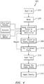
FIG. 4 is a block diagram representing a method of coating an array of internal passageways of a component. -
FIG. 5 is a micrograph of an aluminide coating before any chromizing within a portion of an array of internal passageways prior to chromizing. -
FIG. 6 is a micrograph of a portion of the array of internal passageways in which the aluminide coating that has been chromized. -
FIG. 7 is a micrograph of a component processed with the method of coating the array of internal passageways after 1000 hours in a hot corrosion test at 1350 F (approximately 732°C). -
FIG. 1 schematically illustrates agas turbine engine 20. The exemplarygas turbine engine 20 is disclosed herein as a two-spool turbo fan that generally incorporates afan section 22, acompressor section 24, acombustor section 26 and aturbine section 28. Thefan section 22 drives air along a bypass flowpath and along a core flowpath for compression by thecompressor section 24, communication into thecombustor section 26, then expansion through theturbine section 28. Although depicted as a turbofan in the disclosed non-limiting embodiment, it should be understood that the concepts described herein are not limited to use with turbofans as the teachings may be applied to other types of turbine engine architectures such as low bypass turbofans, turbojets, turboshafts, three-spool (plus fan) turbofans and other non-gas turbine components. - The
engine 20 generally includes alow spool 30 and ahigh spool 32 mounted for rotation an engine central longitudinal axis "A". Thelow spool 30 generally includes aninner shaft 40 that interconnects afan 42, a low pressure compressor ("LPC") 44 and a low pressure turbine ("LPT") 46. Theinner shaft 40 drives thefan 42 directly, or through a gearedarchitecture 48 at a lower speed than thelow spool 30. An exemplary reduction transmission is an epicyclic transmission, namely a planetary or star gear system. - The
high spool 32 includes anouter shaft 50 that interconnects a high pressure compressor ("HPC") 52 and high pressure turbine ("HPT") 54. Acombustor 56 is arranged between thehigh pressure compressor 52 and thehigh pressure turbine 54. Theinner shaft 40 and theouter shaft 50 are concentric and rotate the engine central longitudinal axis "A", which is collinear with their longitudinal axes. - Core airflow is compressed by the
LPC 44, then the HPC 52, mixed with the fuel and burned in thecombustor 56, then expanded over the HPT 54, then theLPT 46. Theturbines high spool 32 andlow spool 30 in response to the expansion. Themain engine shafts structures 38 within thestatic structure 36. - With reference to
FIG. 2 , an enlarged schematic view of a portion of theturbine section 28 is shown by way of example; however, other engine sections will also benefit herefrom. Ashroud assembly 60 within theengine case structure 36 supports a blade outer air seal (BOAS)assembly 62 with a multiple of circumferentially distributedBOAS 64 proximate to a rotor assembly 66 (one schematically shown). - The
shroud assembly 60 and the BOASassembly 62 are axially disposed between a forwardstationary vane ring 68 and an aftstationary vane ring 70. Eachvane ring vanes inner vane platform outer vane platform outer vane platforms engine case structure 36. - The
rotor assembly 66 includes an array ofblades 84 circumferentially disposed around adisk 86. Eachblade 84 includes aroot 88, aplatform 90 and an airfoil 92 (also shown inFIG. 3 ). Theblade roots 88 are received within arim 94 of thedisk 86 and theairfoils 92 extend radially outward such that atip 96 of eachairfoil 92 is closest to the blade outer air seal (BOAS)assembly 62. Theplatform 90 separates a gas path side inclusive of theairfoil 92 and a non-gas path side inclusive of theroot 88. - With reference to
FIG. 3 , theplatform 90 generally separates theroot 88 and theairfoil 92 to define an inner boundary of a gas path. Theairfoil 92 defines a blade chord between aleading edge 98, which may include various forward and/or aft sweep configurations, and a trailingedge 100. Afirst sidewall 102 that may be convex to define a suction side, and asecond sidewall 104 that may be concave to define a pressure side are joined at theleading edge 98 and at the axially spaced trailingedge 100. Thetip 96 extends between thesidewalls platform 90. It should be appreciated that thetip 96 may include a recessed portion. - To resist the high temperature stress environment in the gas path of a turbine engine, each
blade 84 may be formed by casting. It should be appreciated that although ablade 84 with an array of internal passageways 110 (shown schematically) will be described and illustrated in detail, other hot section components including, but not limited to, vanes, turbine shrouds, end walls and other components will also benefit from the teachings herein. - The external airfoil surface may be protected by a protective coating that overlies and contacts the external airfoil surface. Such coatings may be of the MCrAlX type. The terminology "MCrAlX" is a shorthand term of art for a variety of families of overlay protective layers that may be employed as environmental coatings or bond coats in thermal barrier coating systems. In this, and other forms, M refers to nickel, cobalt, iron, and combinations thereof. In some of these protective coatings, the chromium may be omitted. The X denotes elements such as hafnium, zirconium, yttrium, tantalum, rhenium, ruthenium, palladium, platinum, silicon, titanium, boron, carbon, and combinations thereof. Specific compositions are known in the art. Optionally, a ceramic layer overlies and contacts the protective layer. The ceramic layer is preferably yttria-stabilized zirconia, which is a zirconium oxide. Other operable ceramic materials may be used as well. Often, when there is no ceramic layer present, the protective layer is termed an "environmental coating." When there is a ceramic layer present, the protective layer is often referred to as a "bond coat".
- The array of
internal passageways 110 generally includes one ormore feed passages 112 that communicate airflow into a trailingedge cavity 114 within theblade 84. It should be appreciated that the array ofinternal passageways 110 may be of various geometries, numbers and configurations and thefeed passage 112 in this embodiment is the aft most passage that communicates cooling air to the trailingedge cavity 114. Thefeed passage 112 generally receives cooling flow through at least oneinlet 116 within abase 118 of theroot 88. - The trailing
edge cavity 114 may include a multiple of trailing edge cavity features 120 that result in a circuitous and complex cooling airflow path. It should be appreciated that although particular features are delineated within certain general areas, the features may be otherwise arranged or intermingled and still not depart from the disclosure herein. - The array of
internal passageways 110 are generally present in various gas turbine components, such as theexample blade 84, to allow for the passage of cooling air. As gas turbine temperatures have increased, the geometries of these cooling passages have become progressively more circuitous and complex. Theseinternal passages 110, as well as other portions of the workpiece, are often coated with a metallic coating applied via a diffusion chromizing process to prevent hot corrosion. Generally, components are placed in a retort for distillation, Cr-containing vapor species are generated and supplied to the surface of the components via gas phase transport, and a Cr-rich coating is formed. Although effective, the vapor phase chromizing process may suffer from an inability to achieve sufficient coverage and Cr content on some components, particular High Pressure Turbine (HPT) blades that are either very large or that contain very complex internal passages. - The example component workpiece, such as the
blade 84, is typically manufactured of a nickel-base alloy, and more preferably of a nickel-base superalloy. A nickel-base alloy has more nickel than any other element, and a nickel-base superalloy is a nickel-base alloy that is strengthened by the precipitation of gamma prime or a related phase. The component, and thence a substrate and the internal passageways thereof, are thus of nickel-base alloy, and more preferably are a nickel-base superalloy. - In this embodiment, the array of
internal passageways 110 within theblade 84 or other workpiece includes an aluminizedsection 130 and achromized section 132. That is, the entirety of the previously-aluminized array ofinternal passageways 110 are chromized only up to ademarcation 140 such that only thechromized section 132 has a relatively thick (e.g., 1.5 - 3 mil) Cr-rich coating 144. In this embodiment, thedemarcation 140 may be located at 20%-30% the span of theairfoil 92 and more specifically at a 25% span location of theairfoil 92. That is, the previously-aluminized array ofinternal passageways 110 is chromized up to thedemarcation 140. Aluminides are protective in high temperature oxidation and less so in hot corrosion, while the reverse is true for chromizing. - Alternatively, the
demarcation 140 may be defined by a temperature range experienced by theairfoil 92 during operation. For example, thedemarcation 140 may be defined at the location on theairfoil 92 where local temperatures exceed approximately 1600 degree F (approximately 870°C). Typically, high temperature oxidation occurs around 1700F -1800F (925°C-982°C) which appears in the outboard section of theairfoil 92 such that the aluminides in the aluminizedsection 130 forms an aluminum oxide scale this is resistant to oxidation damage at high temperatures while the relativelycooler chromized section 132 is resistant to contaminates at relatively cooler inboard sections. That is, the aluminizedsection 130 and thechromized section 132 provide effective resistance to oxidation and deposit-induced hot corrosion, respectively when flown in polluted environments. - With reference to
FIG. 4 , one disclosed non-limiting embodiment of amethod 200 for applying a location-specific coating is illustrated. The steps or actions described with respect to themethod 200, can be employed with additional steps or other processes as desired. Although aturbine blade 84 is illustrated as the article in the disclosed embodiment, the article may be a metallic article formed of a base alloy substrate. For example, the base alloy substrate is a superalloy. In a further example, the superalloy is a nickel-base alloy. In a still further example, the base alloy is a low-chromium superalloy, such as a superalloy having less than approximately 12% by weight chromium. It should be appreciated that although theblade 84 is illustrated in the disclose embodiment, any such component desired to have internal hot corrosion protection and high temperature oxidation resistance will benefit herefrom. - Initially, the first step of the
process 200 is to aluminize (step 202;FIG. 5 ) the component internals, e.g., the array ofinternal passageways 110. The aluminizing may be accomplished by chemical vapor deposition (CVD), above the pack, or slurry processes. The aluminizing alone will be the mitigation strategy in the outer portions outboard of thedemarcation 140 where high temperature oxidation damage typically dominates. In addition, the externals may be aluminized as well. - The component may be exposed to an aluminum source material such as a chromium-aluminum alloy in the presence of an activator, such as a halide activator, and a cover gas such as argon or hydrogen, at a temperature of between approximately 1900 F - 2100 F (1037 C - 1148 C) for a time of between 1 - 6 hours. The halide activator can be, for instance, a fluoride or a chloride in a solid or gaseous form.
- In another example aluminizing process, the aluminum or aluminum source and activator can be combined with another material such as aluminum oxide powder prior to being deposited on the component. The other material can enhance the deposition of aluminum or the properties of the deposited aluminum. Then, the component is exposed to the aluminum or aluminum mixture at a temperature of less than approximately 1500 F (815 C) for a time of between approximately 2 - 4 hours.
- In another example aluminizing process, the aluminum or aluminum source and activator can be combined with another material such as aluminum oxide powder prior to being deposited on component to enhance the deposition of aluminum or the properties of the deposited aluminum. Then, the component is exposed to the aluminum or aluminum mixture at a temperature of between 1500 F - 1900 F (815 C - 1037 C) for a time of between 2 - 8 hours. In another example process, the aluminum or aluminum source and activator can be combined with another material such as aluminum oxide powder and a binder to form a slurry prior to being deposited on component. The other material can enhance the deposition of aluminum or the properties of the deposited aluminum. Then, the component is exposed to the aluminum or aluminum mixture at a temperature of between 1500 F - 1900 F (815 C - 1037 C) for a time between 2 - 8 hours.
- Any of the aluminizing processes described above can be repeated to incorporate additional aluminum multiple times. Additionally, any of the processes described above can form an aluminum coating that is between approximately 0.5 and 3.0 thousandth of an inch (0.01 to 0.08 mm) thick, for example.
- After aluminizing to provide an aluminized
coating 142 in the array ofinternal passageways 110, the component may be masked (step 204). The mask may be performed via plugging/blocking of the openings to the array ofinternal passageways 110. Other particular external areas such as the root, underplatform, and airfoil external surfaces may also be masked by sacrificial coating, taping, mechanical fixturing/masking or the like. - Next, the component is chromized (
step 206;FIG. 6 ) up to thedemarcation 140. For example, only an inboard portion, e.g., from theroot 88,platform 90, and theairfoil 92, of the component is dipped into a tank containing a chromizing slurry so that the slurry is applied to the internal surfaces up to the desireddemarcation 140 of theairfoil 92. The chromium slurry, for example, can be flowed through the component to achieve coverage on complex geometries, here, the array ofinternal passageways 110. The chromium slurry may alternatively be applied to the component, for example, by pouring, injecting, or otherwise flowing the slurry into the array ofinternal passageways 110. In another disclosed non-limiting embodiment, a portion of the component is dipped therein. Alternately, the chromium slurry is applied via other carriers, devices, and/or methods. The resultant chromium enriched diffusion coating 144 (FIG. 6 ; the aluminide after being chromized) in terms of microstructure and thickness is similar to the aluminide coating 142 (FIG. 5 ; before any chromizing) but a substantial amount of the aluminum in the coating is replaced with chromium. The vapor aluminide shown inFIG. 5 may be deposited by a high temperature, low activity aluminizing process. An outer layer (dimension B) which may be about 0.9 mil, is the beta-NiAl phase, which grows outward from the original alloy surface; the remainder of the coating is the inter-diffusion zone (IDZ). The entire chromium enriched diffusion coating 144 (FIG. 6 ; dimension B + X) in one example is about 1.6 mil. The outer layer of the coating (dimension B;FIG. 6 ) was formerly beta-NiAl that was converted to either Cr-rich gamma-Ni solid solution or gamma + alpha-Cr upon chromizing. - The chromium slurry may include a mixture of chromium powder, chromium Chloride (CrCl3) particles as an activator, and, optionally, an organic binder. While using a slurry with no oxide filler is an option, other embodiments may utilize either Al2O3 or SiO2 in this process. SiO2 has the benefit of being removable via autoclave with a basic solution of KOH or NaOH, which may be desirable for the array of
internal passageways 110. Other slurry coatings contain aluminum oxide filler, but the presence of such a filler in a coating slurry that is used to coat internal surfaces such as the array ofinternal passageways 110 may be a primary cause of undesirable obstruction and/or flow disturbances within the array ofinternal passageways 110. - The chromium (Cr) slurry, in one example in terms of weight percentages, includes 48.5-68% by weight chromium powder, 0.9-3.4% by weight chromium Chloride (CrCl3) particles, and 30-50% by weight organic binder. The resultant chromium (Cr) slurry forms a low-viscosity fluid capable of being flowed through internal passages. In one example, the slurry has a viscosity of 100-200 cP. Any operable organic binder may be used. Examples include, but are not limited to, B4 (n-propyl bromide-based organic binder such as that from Akron Paint and Varnish) and Klucel H (hydroxypropyl cellulose), and mixtures thereof. Other organic binders such as a water based organic binder may alternatively be utilized.
- The chromium (Cr) slurry, in another example without an organic binder in terms of weight percentages, includes 97% by weight chromium powder and 0.03% by weight chromium Chloride (CrCl3) particles.
- Next, the excess chromium slurry is drained away (step 208). Simply allowing the relatively viscous chromium slurry to flow out of the
internal passageways 110 may perform such draining. - The chromium slurry is then dried to drive off the organic binder (step 210). The drying evaporates the flowable carrier component of the organic binder (e.g., flowable organic solvents and water) of the chromium slurry, leaving the organic binder that binds the particles together. Driving off the organic binder is performed at a relatively low temperature for short periods of time. In one example, drying of the binder is performed at 200F (93C) for 1 hour. Alternatively, the drying could be performed at room temperature given a commensurate greater time period. The applying, draining and drying steps may also be repeated multiple times to achieve a desired thickness and/or coverage.
- Next, the component is heat treated (step 212). In one example, heat treat may be accomplished at a temperature of from 1600F (871C) to 2100F (1149C) most preferably from 1925F (1052C) to 2000F (1093C), for a time of 4 - 8 hours, preferably, 5 - 6 hours. The heat treating may be performed in an inert (e.g., argon) or reducing (e.g., hydrogen) atmosphere. In the case of the inert atmosphere, the atmosphere is largely free of oxygen and oxygen-containing species such as water vapor.
- The heat treat allows, through a mechanism involving the reaction of the Cr powder with the activator, gas phase transport of Cr-containing species to the component surface, and subsequent diffusion of Cr into the parent material, the formation of a coating that, in one disclosed non-limiting embodiment, is 10 - 50 microns thick chromium-enriched single phase γ face centered cubic Ni-based solid solution layer that prevents hot corrosion. There may be some transition zone to which the Cr-rich vapors travel, but the outboard portion of the blade will remain aluminized with minimum Cr deposition. If the aluminizing is accomplished via a slurry process, the possibility exists to only conduct one heat treatment.
- After the heat treatment the "spent" slurry is removed (step 214). There is essentially a friable crust of Cr-containing powder on the array of
internal passageways 110 after the heat treatment, and this is to be removed. In one example, warm hydrogen chloride (HCl) may be utilized to dissolve away this material. Alternatively, or in addition thereto, physical methods, e.g., an autoclave, high pressure flushing with water, or others may be utilized to remove the crust of Cr-containing powder. - Next, an overlay coating may be applied to gas path surfaces of the
blade 84 such as theairfoil 92 and the upper surfaces of the platform 90 (step 216). The portions of the exterior may be along essentially the entire exterior or a portion of the exterior surface and gaspath-facing surface(s) of the platform, the shroud, etc. The overlay coating as defined herein includes, but is not limited to, cathodic Arc metallic bondcoat, and external duplex electron beam-physical vapor deposition (EB-PVD) ceramic coatings. - Detailed investigation of fielded components has shown that hot corrosion damage commonly occurs on the internal surfaces in cooler locations, such as towards the base of the airfoil and below the platform, while the airfoil internals are commonly challenged in high temperature oxidation further outboard towards the tip. By using this location-specific coating process, both degradation modes can be addressed individually. Hot corrosion testing of the coating deposited in the relatively cooler locations of the airfoil internals shows no coating penetration after 1000 hours of hot corrosion exposure at 1350 F (approximately 732°C) in a corrosive sulfate mixture (
FIG. 7 ). - The use of the terms "a", "an", "the", and similar references in the context of description (especially in the context of the following claims) are to be construed to cover both the singular and the plural, unless otherwise indicated herein or specifically contradicted by context. The modifier "" used in connection with a quantity is inclusive of the stated value and has the meaning dictated by the context (e.g., it includes the degree of error associated with measurement of the particular quantity). All ranges disclosed herein are inclusive of the endpoints, and the endpoints are independently combinable with each other. It should be appreciated that relative positional terms such as "forward", "aft", "upper", "lower", "above", "below" and the like are with reference to normal operational attitude and should not be considered otherwise limiting.
- Although the different non-limiting embodiments have specific illustrated components, the embodiments of this invention are not limited to those particular combinations. It is possible to use some of the components or features from any of the non-limiting embodiments in combination with features or components from any of the other non-limiting embodiments.
- It should be appreciated that like reference numerals identify corresponding or similar elements throughout the several drawings. It should also be appreciated that although a particular component arrangement is disclosed in the illustrated embodiment, other arrangements will benefit herefrom.
- Although particular step sequences are shown, described, and claimed, it should be understood that steps may be performed in any order, separated or combined unless otherwise indicated and will still benefit from the present disclosure.
- The foregoing description is exemplary rather than defined by the limitations within. Various non-limiting embodiments are disclosed herein, however, one of ordinary skill in the art would recognize that various modifications and variations in light of the above teachings will fall within the scope of the appended claims. It is therefore to be understood that within the scope of the appended claims, the disclosure may be practiced other than as specifically described. For that reason, the appended claims should be studied to determine true scope and content.
Claims (15)
- A method of coating a component, comprising:aluminizing (202) an array of internal passageways (110) within the component; andchromizing (206) a portion of the array of internal passageways (110) within the component after aluminizing (202) the array of internal passageways (110).
- The method as recited in claim 1, wherein chromizing (206) the portion of the array of internal passageways (110) comprises chromizing (206) up to a demarcation (140).
- The method as recited in claim 2, wherein the demarcation (140) is located at 20%-30% of an airfoil span of the component.
- The method as recited in claim 2, wherein the demarcation (140) is at 25% of an airfoil span of the component.
- The method as recited in claim 2, wherein the demarcation (140) is at an airfoil span location where local temperatures exceed approximately 1600 degree F (approximately 870°C).
- The method as recited in any preceding claim, wherein chromizing (206) the portion of the array of internal passageways (110) comprises applying a chromium slurry (206) into the array of internal passageways (110) within the component.
- The method as recited in claim 6, wherein the chromium slurry has a viscosity of 100-200 cP.
- The method as recited in any preceding claim, further comprising applying a thermal barrier coat atop a bond coat on an external surface of the component.
- A component, comprising:a substrate having an array of aluminized internal passageways (110) within the component; anda chromium-enriched coating (144) within a portion of the array of internal passageways (110).
- The component as recited in claim 9, wherein the substrate comprises a superalloy.
- The component as recited in claim 9 or 10, wherein the chromium-enriched coating (144) within the portion of the array of internal passageways (110) is located at an inboard section of the component,
wherein the chromium-enriched coating (144) within the portion of the array of internal passageways (110) is optionally located up to a demarcation (140) that is located at 20%-30% of an airfoil span of the component,
wherein the chromium-enriched coating (144) within the portion of the array of internal passageways (110) is optionally located up to a demarcation (140) that is located at 25% of an airfoil span of the component. - The component as recited in any of claims 9 to 11, wherein the chromium-enriched coating (144) within the portion of the array of internal passageways (110) is located up to an airfoil span location where local temperatures exceed approximately 1600 degree F (approximately 870°C).
- The component as recited in any of claims 9 to 12, wherein the chromium-enriched coating (144) is 10-50 microns thick.
- A component, comprising:an airfoil having an array of aluminized internal passageways, the array of aluminized internal passageways chromized up to a demarcation,wherein the demarcation is optionally located at 20%-30% of a span of the airfoil,wherein the demarcation is optionally located at 25% of a span of the airfoil,wherein the demarcation is optionally located at an airfoil span where local temperatures exceed approximately 1600 degree F (approximately 870°C).
- The component as recited in any of claims 9 to 14, wherein the component is a turbine blade.
Applications Claiming Priority (1)
| Application Number | Priority Date | Filing Date | Title |
|---|---|---|---|
| US15/923,432 US20190284941A1 (en) | 2018-03-16 | 2018-03-16 | Location-specific slurry based coatings for internally-cooled component and process therefor |
Publications (2)
| Publication Number | Publication Date |
|---|---|
| EP3540089A1 true EP3540089A1 (en) | 2019-09-18 |
| EP3540089B1 EP3540089B1 (en) | 2023-04-26 |
Family
ID=65817800
Family Applications (1)
| Application Number | Title | Priority Date | Filing Date |
|---|---|---|---|
| EP19162920.3A Active EP3540089B1 (en) | 2018-03-16 | 2019-03-14 | Location-specific slurry based coatings for internally-cooled component and process therefor |
Country Status (2)
| Country | Link |
|---|---|
| US (2) | US20190284941A1 (en) |
| EP (1) | EP3540089B1 (en) |
Cited By (2)
| Publication number | Priority date | Publication date | Assignee | Title |
|---|---|---|---|---|
| EP3783128A1 (en) * | 2019-08-23 | 2021-02-24 | Raytheon Technologies Corporation | Slurry based diffusion coatings for blade under platform of internally-cooled components and process therefor |
| EP3964691A1 (en) * | 2020-08-27 | 2022-03-09 | Raytheon Technologies Corporation | Cooling arrangement including alternating pedestals for gas turbine engine components |
Families Citing this family (3)
| Publication number | Priority date | Publication date | Assignee | Title |
|---|---|---|---|---|
| US10995039B1 (en) | 2019-12-20 | 2021-05-04 | General Electric Company | Methods of forming ceramic matrix composites using sacrificial fibers and non-wetting coating |
| US20240418091A1 (en) * | 2023-06-13 | 2024-12-19 | Rtx Corporation | Turbine Airfoil Coating |
| US12467372B2 (en) | 2023-06-13 | 2025-11-11 | Rtx Corporation | Turbine airfoil coating |
Citations (3)
| Publication number | Priority date | Publication date | Assignee | Title |
|---|---|---|---|---|
| US20150197841A1 (en) * | 2014-01-14 | 2015-07-16 | Zhihong Tang | Methods of applying chromium diffusion coatings onto selective regions of a component |
| EP2975153A2 (en) * | 2014-07-18 | 2016-01-20 | United Technologies Corporation | Chromium-enriched diffused aluminide coating |
| EP3012343A1 (en) * | 2014-10-20 | 2016-04-27 | United Technologies Corporation | Coating system for internally-cooled component and process therefor |
Family Cites Families (20)
| Publication number | Priority date | Publication date | Assignee | Title |
|---|---|---|---|---|
| EP0846788A1 (en) | 1996-12-06 | 1998-06-10 | Siemens Aktiengesellschaft | An article having a superalloy substrate and an enrichment layer placed thereon, and methods of its manufacturing |
| EP1115906B1 (en) * | 1998-09-21 | 2003-02-05 | Siemens Aktiengesellschaft | Method for processing the interior of a hollow part |
| US7026011B2 (en) | 2003-02-04 | 2006-04-11 | General Electric Company | Aluminide coating of gas turbine engine blade |
| US6905730B2 (en) | 2003-07-08 | 2005-06-14 | General Electric Company | Aluminide coating of turbine engine component |
| GB0409486D0 (en) * | 2004-04-28 | 2004-06-02 | Diffusion Alloys Ltd | Coatings for turbine blades |
| EP1772531A1 (en) * | 2005-10-07 | 2007-04-11 | Siemens Aktiengesellschaft | Method and apparatus for internal coating. |
| EP1772529A1 (en) * | 2005-10-07 | 2007-04-11 | Siemens Aktiengesellschaft | Dry chemical composition, use thereof to form a layer system and method for coating |
| US20090020216A1 (en) * | 2007-07-20 | 2009-01-22 | Gm Global Technology Operations, Inc. | Method Of Making Tailored Core Laminated Sheet Metal |
| US8545185B2 (en) * | 2007-12-19 | 2013-10-01 | General Electric Company | Turbine engine components with environmental protection for interior passages |
| GB0902633D0 (en) * | 2009-02-18 | 2009-04-01 | Rolls Royce Plc | A method and an arrangement for vapour phase coating of an internal surface of at least one hollow article |
| EP2743369A1 (en) * | 2012-12-11 | 2014-06-18 | Siemens Aktiengesellschaft | Coating system, method of coating a substrate, and gas turbine component |
| JP6480662B2 (en) * | 2013-03-13 | 2019-03-13 | ハウメット コーポレイションHowmet Corporation | Maskant used for aluminizing turbine parts |
| US10364490B2 (en) * | 2013-12-10 | 2019-07-30 | United Technologies Corporation | Chromizing over cathodic arc coating |
| US20160304993A1 (en) * | 2014-11-05 | 2016-10-20 | Cal Poly Pomona Foundation, Inc. | Ductile nickel-based austenitic alloy coating and method of manufacturing |
| CA2937308C (en) * | 2015-07-27 | 2023-10-24 | Pratt & Whitney Canada Corp. | Turbine blade with hot-corrosion-resistant coating |
| US20170241273A1 (en) | 2016-02-18 | 2017-08-24 | General Electric Company | System and Method for Simultaneously Depositing Multiple Coatings on a Turbine Blade of a Gas Turbine Engine |
| US20180016672A1 (en) | 2016-07-12 | 2018-01-18 | United Technologies Corporation | Method of chromizing an article including internal passages of the article |
| DE102017213553A1 (en) * | 2017-08-04 | 2019-02-07 | MTU Aero Engines AG | VESSEL FOR FLOW MACHINE WITH VARIOUS DIFFUSION PROTECTION LAYERS AND METHOD OF MANUFACTURING THEREOF |
| US11970953B2 (en) * | 2019-08-23 | 2024-04-30 | Rtx Corporation | Slurry based diffusion coatings for blade under platform of internally-cooled components and process therefor |
| CN111575646A (en) * | 2020-06-11 | 2020-08-25 | 南京国重新金属材料研究院有限公司 | Chromizing and aluminizing process for aero-engine blade |
-
2018
- 2018-03-16 US US15/923,432 patent/US20190284941A1/en not_active Abandoned
-
2019
- 2019-03-14 EP EP19162920.3A patent/EP3540089B1/en active Active
-
2021
- 2021-02-10 US US17/172,746 patent/US11719105B2/en active Active
Patent Citations (3)
| Publication number | Priority date | Publication date | Assignee | Title |
|---|---|---|---|---|
| US20150197841A1 (en) * | 2014-01-14 | 2015-07-16 | Zhihong Tang | Methods of applying chromium diffusion coatings onto selective regions of a component |
| EP2975153A2 (en) * | 2014-07-18 | 2016-01-20 | United Technologies Corporation | Chromium-enriched diffused aluminide coating |
| EP3012343A1 (en) * | 2014-10-20 | 2016-04-27 | United Technologies Corporation | Coating system for internally-cooled component and process therefor |
Cited By (5)
| Publication number | Priority date | Publication date | Assignee | Title |
|---|---|---|---|---|
| EP3783128A1 (en) * | 2019-08-23 | 2021-02-24 | Raytheon Technologies Corporation | Slurry based diffusion coatings for blade under platform of internally-cooled components and process therefor |
| US11970953B2 (en) | 2019-08-23 | 2024-04-30 | Rtx Corporation | Slurry based diffusion coatings for blade under platform of internally-cooled components and process therefor |
| US12320271B2 (en) | 2019-08-23 | 2025-06-03 | Rtx Corporation | Slurry based diffusion coatings for blade under platform of internally-cooled components and process therefor |
| EP3964691A1 (en) * | 2020-08-27 | 2022-03-09 | Raytheon Technologies Corporation | Cooling arrangement including alternating pedestals for gas turbine engine components |
| US11352902B2 (en) | 2020-08-27 | 2022-06-07 | Aytheon Technologies Corporation | Cooling arrangement including alternating pedestals for gas turbine engine components |
Also Published As
| Publication number | Publication date |
|---|---|
| US11719105B2 (en) | 2023-08-08 |
| US20190284941A1 (en) | 2019-09-19 |
| EP3540089B1 (en) | 2023-04-26 |
| US20210164353A1 (en) | 2021-06-03 |
Similar Documents
| Publication | Publication Date | Title |
|---|---|---|
| US11719105B2 (en) | Process for location-specific slurry based coatings for internally-cooled component | |
| US10156007B2 (en) | Methods of applying chromium diffusion coatings onto selective regions of a component | |
| US12320271B2 (en) | Slurry based diffusion coatings for blade under platform of internally-cooled components and process therefor | |
| US6273678B1 (en) | Modified diffusion aluminide coating for internal surfaces of gas turbine components | |
| US8545185B2 (en) | Turbine engine components with environmental protection for interior passages | |
| US6969558B2 (en) | Low sulfur article having a platinum-aluminide protective layer, and its preparation | |
| JP2010126812A (en) | Repair method for tbc coated turbine components | |
| EP1820876B1 (en) | Method of coating gas turbine components | |
| CN110325666A (en) | Coatings for airfoils of gas turbine engines and methods of applying coatings | |
| US10914181B2 (en) | Blade or vane for turbomachine with different diffusion protective coatings and method for manufacture thereof | |
| EP4361314A1 (en) | Coating system for components in need of repair | |
| EP3012343B1 (en) | Coating system for internally-cooled component and process therefor | |
| US6896488B2 (en) | Bond coat process for thermal barrier coating | |
| TR201808813T4 (en) | Alloy, protective coating and component. | |
| JP2008002468A (en) | Oxidation resistant metal phosphate coating | |
| WO2018038738A1 (en) | Multi-layer protective coating enabling nickel diffusion |
Legal Events
| Date | Code | Title | Description |
|---|---|---|---|
| PUAI | Public reference made under article 153(3) epc to a published international application that has entered the european phase |
Free format text: ORIGINAL CODE: 0009012 |
|
| STAA | Information on the status of an ep patent application or granted ep patent |
Free format text: STATUS: THE APPLICATION HAS BEEN PUBLISHED |
|
| AK | Designated contracting states |
Kind code of ref document: A1 Designated state(s): AL AT BE BG CH CY CZ DE DK EE ES FI FR GB GR HR HU IE IS IT LI LT LU LV MC MK MT NL NO PL PT RO RS SE SI SK SM TR |
|
| AX | Request for extension of the european patent |
Extension state: BA ME |
|
| STAA | Information on the status of an ep patent application or granted ep patent |
Free format text: STATUS: REQUEST FOR EXAMINATION WAS MADE |
|
| 17P | Request for examination filed |
Effective date: 20200310 |
|
| RBV | Designated contracting states (corrected) |
Designated state(s): AL AT BE BG CH CY CZ DE DK EE ES FI FR GB GR HR HU IE IS IT LI LT LU LV MC MK MT NL NO PL PT RO RS SE SI SK SM TR |
|
| RAP1 | Party data changed (applicant data changed or rights of an application transferred) |
Owner name: RAYTHEON TECHNOLOGIES CORPORATION |
|
| GRAP | Despatch of communication of intention to grant a patent |
Free format text: ORIGINAL CODE: EPIDOSNIGR1 |
|
| STAA | Information on the status of an ep patent application or granted ep patent |
Free format text: STATUS: GRANT OF PATENT IS INTENDED |
|
| INTG | Intention to grant announced |
Effective date: 20220928 |
|
| GRAS | Grant fee paid |
Free format text: ORIGINAL CODE: EPIDOSNIGR3 |
|
| GRAA | (expected) grant |
Free format text: ORIGINAL CODE: 0009210 |
|
| STAA | Information on the status of an ep patent application or granted ep patent |
Free format text: STATUS: THE PATENT HAS BEEN GRANTED |
|
| AK | Designated contracting states |
Kind code of ref document: B1 Designated state(s): AL AT BE BG CH CY CZ DE DK EE ES FI FR GB GR HR HU IE IS IT LI LT LU LV MC MK MT NL NO PL PT RO RS SE SI SK SM TR |
|
| REG | Reference to a national code |
Ref country code: GB Ref legal event code: FG4D |
|
| REG | Reference to a national code |
Ref country code: CH Ref legal event code: EP |
|
| REG | Reference to a national code |
Ref country code: DE Ref legal event code: R096 Ref document number: 602019027939 Country of ref document: DE |
|
| REG | Reference to a national code |
Ref country code: AT Ref legal event code: REF Ref document number: 1562866 Country of ref document: AT Kind code of ref document: T Effective date: 20230515 |
|
| REG | Reference to a national code |
Ref country code: IE Ref legal event code: FG4D |
|
| P01 | Opt-out of the competence of the unified patent court (upc) registered |
Effective date: 20230603 |
|
| REG | Reference to a national code |
Ref country code: LT Ref legal event code: MG9D |
|
| REG | Reference to a national code |
Ref country code: NL Ref legal event code: MP Effective date: 20230426 |
|
| REG | Reference to a national code |
Ref country code: AT Ref legal event code: MK05 Ref document number: 1562866 Country of ref document: AT Kind code of ref document: T Effective date: 20230426 |
|
| PG25 | Lapsed in a contracting state [announced via postgrant information from national office to epo] |
Ref country code: NL Free format text: LAPSE BECAUSE OF FAILURE TO SUBMIT A TRANSLATION OF THE DESCRIPTION OR TO PAY THE FEE WITHIN THE PRESCRIBED TIME-LIMIT Effective date: 20230426 |
|
| PG25 | Lapsed in a contracting state [announced via postgrant information from national office to epo] |
Ref country code: SE Free format text: LAPSE BECAUSE OF FAILURE TO SUBMIT A TRANSLATION OF THE DESCRIPTION OR TO PAY THE FEE WITHIN THE PRESCRIBED TIME-LIMIT Effective date: 20230426 Ref country code: PT Free format text: LAPSE BECAUSE OF FAILURE TO SUBMIT A TRANSLATION OF THE DESCRIPTION OR TO PAY THE FEE WITHIN THE PRESCRIBED TIME-LIMIT Effective date: 20230828 Ref country code: NO Free format text: LAPSE BECAUSE OF FAILURE TO SUBMIT A TRANSLATION OF THE DESCRIPTION OR TO PAY THE FEE WITHIN THE PRESCRIBED TIME-LIMIT Effective date: 20230726 Ref country code: ES Free format text: LAPSE BECAUSE OF FAILURE TO SUBMIT A TRANSLATION OF THE DESCRIPTION OR TO PAY THE FEE WITHIN THE PRESCRIBED TIME-LIMIT Effective date: 20230426 Ref country code: AT Free format text: LAPSE BECAUSE OF FAILURE TO SUBMIT A TRANSLATION OF THE DESCRIPTION OR TO PAY THE FEE WITHIN THE PRESCRIBED TIME-LIMIT Effective date: 20230426 |
|
| RAP4 | Party data changed (patent owner data changed or rights of a patent transferred) |
Owner name: RTX CORPORATION |
|
| PG25 | Lapsed in a contracting state [announced via postgrant information from national office to epo] |
Ref country code: RS Free format text: LAPSE BECAUSE OF FAILURE TO SUBMIT A TRANSLATION OF THE DESCRIPTION OR TO PAY THE FEE WITHIN THE PRESCRIBED TIME-LIMIT Effective date: 20230426 Ref country code: PL Free format text: LAPSE BECAUSE OF FAILURE TO SUBMIT A TRANSLATION OF THE DESCRIPTION OR TO PAY THE FEE WITHIN THE PRESCRIBED TIME-LIMIT Effective date: 20230426 Ref country code: LV Free format text: LAPSE BECAUSE OF FAILURE TO SUBMIT A TRANSLATION OF THE DESCRIPTION OR TO PAY THE FEE WITHIN THE PRESCRIBED TIME-LIMIT Effective date: 20230426 Ref country code: LT Free format text: LAPSE BECAUSE OF FAILURE TO SUBMIT A TRANSLATION OF THE DESCRIPTION OR TO PAY THE FEE WITHIN THE PRESCRIBED TIME-LIMIT Effective date: 20230426 Ref country code: IS Free format text: LAPSE BECAUSE OF FAILURE TO SUBMIT A TRANSLATION OF THE DESCRIPTION OR TO PAY THE FEE WITHIN THE PRESCRIBED TIME-LIMIT Effective date: 20230826 Ref country code: HR Free format text: LAPSE BECAUSE OF FAILURE TO SUBMIT A TRANSLATION OF THE DESCRIPTION OR TO PAY THE FEE WITHIN THE PRESCRIBED TIME-LIMIT Effective date: 20230426 Ref country code: GR Free format text: LAPSE BECAUSE OF FAILURE TO SUBMIT A TRANSLATION OF THE DESCRIPTION OR TO PAY THE FEE WITHIN THE PRESCRIBED TIME-LIMIT Effective date: 20230727 |
|
| PG25 | Lapsed in a contracting state [announced via postgrant information from national office to epo] |
Ref country code: FI Free format text: LAPSE BECAUSE OF FAILURE TO SUBMIT A TRANSLATION OF THE DESCRIPTION OR TO PAY THE FEE WITHIN THE PRESCRIBED TIME-LIMIT Effective date: 20230426 |
|
| PG25 | Lapsed in a contracting state [announced via postgrant information from national office to epo] |
Ref country code: SK Free format text: LAPSE BECAUSE OF FAILURE TO SUBMIT A TRANSLATION OF THE DESCRIPTION OR TO PAY THE FEE WITHIN THE PRESCRIBED TIME-LIMIT Effective date: 20230426 |
|
| REG | Reference to a national code |
Ref country code: DE Ref legal event code: R097 Ref document number: 602019027939 Country of ref document: DE |
|
| PG25 | Lapsed in a contracting state [announced via postgrant information from national office to epo] |
Ref country code: SM Free format text: LAPSE BECAUSE OF FAILURE TO SUBMIT A TRANSLATION OF THE DESCRIPTION OR TO PAY THE FEE WITHIN THE PRESCRIBED TIME-LIMIT Effective date: 20230426 Ref country code: SK Free format text: LAPSE BECAUSE OF FAILURE TO SUBMIT A TRANSLATION OF THE DESCRIPTION OR TO PAY THE FEE WITHIN THE PRESCRIBED TIME-LIMIT Effective date: 20230426 Ref country code: RO Free format text: LAPSE BECAUSE OF FAILURE TO SUBMIT A TRANSLATION OF THE DESCRIPTION OR TO PAY THE FEE WITHIN THE PRESCRIBED TIME-LIMIT Effective date: 20230426 Ref country code: EE Free format text: LAPSE BECAUSE OF FAILURE TO SUBMIT A TRANSLATION OF THE DESCRIPTION OR TO PAY THE FEE WITHIN THE PRESCRIBED TIME-LIMIT Effective date: 20230426 Ref country code: DK Free format text: LAPSE BECAUSE OF FAILURE TO SUBMIT A TRANSLATION OF THE DESCRIPTION OR TO PAY THE FEE WITHIN THE PRESCRIBED TIME-LIMIT Effective date: 20230426 Ref country code: CZ Free format text: LAPSE BECAUSE OF FAILURE TO SUBMIT A TRANSLATION OF THE DESCRIPTION OR TO PAY THE FEE WITHIN THE PRESCRIBED TIME-LIMIT Effective date: 20230426 |
|
| PLBE | No opposition filed within time limit |
Free format text: ORIGINAL CODE: 0009261 |
|
| STAA | Information on the status of an ep patent application or granted ep patent |
Free format text: STATUS: NO OPPOSITION FILED WITHIN TIME LIMIT |
|
| 26N | No opposition filed |
Effective date: 20240129 |
|
| PG25 | Lapsed in a contracting state [announced via postgrant information from national office to epo] |
Ref country code: SI Free format text: LAPSE BECAUSE OF FAILURE TO SUBMIT A TRANSLATION OF THE DESCRIPTION OR TO PAY THE FEE WITHIN THE PRESCRIBED TIME-LIMIT Effective date: 20230426 |
|
| PG25 | Lapsed in a contracting state [announced via postgrant information from national office to epo] |
Ref country code: SI Free format text: LAPSE BECAUSE OF FAILURE TO SUBMIT A TRANSLATION OF THE DESCRIPTION OR TO PAY THE FEE WITHIN THE PRESCRIBED TIME-LIMIT Effective date: 20230426 Ref country code: IT Free format text: LAPSE BECAUSE OF FAILURE TO SUBMIT A TRANSLATION OF THE DESCRIPTION OR TO PAY THE FEE WITHIN THE PRESCRIBED TIME-LIMIT Effective date: 20230426 |
|
| REG | Reference to a national code |
Ref country code: CH Ref legal event code: PL |
|
| PG25 | Lapsed in a contracting state [announced via postgrant information from national office to epo] |
Ref country code: BG Free format text: LAPSE BECAUSE OF FAILURE TO SUBMIT A TRANSLATION OF THE DESCRIPTION OR TO PAY THE FEE WITHIN THE PRESCRIBED TIME-LIMIT Effective date: 20230426 |
|
| PG25 | Lapsed in a contracting state [announced via postgrant information from national office to epo] |
Ref country code: LU Free format text: LAPSE BECAUSE OF NON-PAYMENT OF DUE FEES Effective date: 20240314 |
|
| PG25 | Lapsed in a contracting state [announced via postgrant information from national office to epo] |
Ref country code: MC Free format text: LAPSE BECAUSE OF FAILURE TO SUBMIT A TRANSLATION OF THE DESCRIPTION OR TO PAY THE FEE WITHIN THE PRESCRIBED TIME-LIMIT Effective date: 20230426 |
|
| PG25 | Lapsed in a contracting state [announced via postgrant information from national office to epo] |
Ref country code: MC Free format text: LAPSE BECAUSE OF FAILURE TO SUBMIT A TRANSLATION OF THE DESCRIPTION OR TO PAY THE FEE WITHIN THE PRESCRIBED TIME-LIMIT Effective date: 20230426 Ref country code: LU Free format text: LAPSE BECAUSE OF NON-PAYMENT OF DUE FEES Effective date: 20240314 Ref country code: BG Free format text: LAPSE BECAUSE OF FAILURE TO SUBMIT A TRANSLATION OF THE DESCRIPTION OR TO PAY THE FEE WITHIN THE PRESCRIBED TIME-LIMIT Effective date: 20230426 |
|
| REG | Reference to a national code |
Ref country code: BE Ref legal event code: MM Effective date: 20240331 |
|
| PG25 | Lapsed in a contracting state [announced via postgrant information from national office to epo] |
Ref country code: BE Free format text: LAPSE BECAUSE OF NON-PAYMENT OF DUE FEES Effective date: 20240331 |
|
| PG25 | Lapsed in a contracting state [announced via postgrant information from national office to epo] |
Ref country code: IE Free format text: LAPSE BECAUSE OF NON-PAYMENT OF DUE FEES Effective date: 20240314 |
|
| PG25 | Lapsed in a contracting state [announced via postgrant information from national office to epo] |
Ref country code: IE Free format text: LAPSE BECAUSE OF NON-PAYMENT OF DUE FEES Effective date: 20240314 Ref country code: BE Free format text: LAPSE BECAUSE OF NON-PAYMENT OF DUE FEES Effective date: 20240331 Ref country code: CH Free format text: LAPSE BECAUSE OF NON-PAYMENT OF DUE FEES Effective date: 20240331 |
|
| PG25 | Lapsed in a contracting state [announced via postgrant information from national office to epo] |
Ref country code: CY Free format text: LAPSE BECAUSE OF FAILURE TO SUBMIT A TRANSLATION OF THE DESCRIPTION OR TO PAY THE FEE WITHIN THE PRESCRIBED TIME-LIMIT; INVALID AB INITIO Effective date: 20190314 |
|
| PG25 | Lapsed in a contracting state [announced via postgrant information from national office to epo] |
Ref country code: HU Free format text: LAPSE BECAUSE OF FAILURE TO SUBMIT A TRANSLATION OF THE DESCRIPTION OR TO PAY THE FEE WITHIN THE PRESCRIBED TIME-LIMIT; INVALID AB INITIO Effective date: 20190314 |
|
| REG | Reference to a national code |
Ref country code: DE Ref legal event code: R081 Ref document number: 602019027939 Country of ref document: DE Owner name: RTX CORPORATION (N.D.GES.D. STAATES DELAWARE),, US Free format text: FORMER OWNER: RAYTHEON TECHNOLOGIES CORPORATION, FARMINGTON, CT, US |
|
| PG25 | Lapsed in a contracting state [announced via postgrant information from national office to epo] |
Ref country code: TR Free format text: LAPSE BECAUSE OF FAILURE TO SUBMIT A TRANSLATION OF THE DESCRIPTION OR TO PAY THE FEE WITHIN THE PRESCRIBED TIME-LIMIT Effective date: 20230426 |
|
| PGFP | Annual fee paid to national office [announced via postgrant information from national office to epo] |
Ref country code: GB Payment date: 20260220 Year of fee payment: 8 |
|
| PGFP | Annual fee paid to national office [announced via postgrant information from national office to epo] |
Ref country code: DE Payment date: 20260219 Year of fee payment: 8 |
|
| PGFP | Annual fee paid to national office [announced via postgrant information from national office to epo] |
Ref country code: FR Payment date: 20260220 Year of fee payment: 8 |