EP1820876B1 - Method of coating gas turbine components - Google Patents
Method of coating gas turbine components Download PDFInfo
- Publication number
- EP1820876B1 EP1820876B1 EP07101752A EP07101752A EP1820876B1 EP 1820876 B1 EP1820876 B1 EP 1820876B1 EP 07101752 A EP07101752 A EP 07101752A EP 07101752 A EP07101752 A EP 07101752A EP 1820876 B1 EP1820876 B1 EP 1820876B1
- Authority
- EP
- European Patent Office
- Prior art keywords
- coating
- aluminum
- turbine part
- approximately
- internal
- Prior art date
- Legal status (The legal status is an assumption and is not a legal conclusion. Google has not performed a legal analysis and makes no representation as to the accuracy of the status listed.)
- Expired - Fee Related
Links
Images


Classifications
-
- C—CHEMISTRY; METALLURGY
- C23—COATING METALLIC MATERIAL; COATING MATERIAL WITH METALLIC MATERIAL; CHEMICAL SURFACE TREATMENT; DIFFUSION TREATMENT OF METALLIC MATERIAL; COATING BY VACUUM EVAPORATION, BY SPUTTERING, BY ION IMPLANTATION OR BY CHEMICAL VAPOUR DEPOSITION, IN GENERAL; INHIBITING CORROSION OF METALLIC MATERIAL OR INCRUSTATION IN GENERAL
- C23C—COATING METALLIC MATERIAL; COATING MATERIAL WITH METALLIC MATERIAL; SURFACE TREATMENT OF METALLIC MATERIAL BY DIFFUSION INTO THE SURFACE, BY CHEMICAL CONVERSION OR SUBSTITUTION; COATING BY VACUUM EVAPORATION, BY SPUTTERING, BY ION IMPLANTATION OR BY CHEMICAL VAPOUR DEPOSITION, IN GENERAL
- C23C10/00—Solid state diffusion of only metal elements or silicon into metallic material surfaces
- C23C10/04—Diffusion into selected surface areas, e.g. using masks
-
- C—CHEMISTRY; METALLURGY
- C23—COATING METALLIC MATERIAL; COATING MATERIAL WITH METALLIC MATERIAL; CHEMICAL SURFACE TREATMENT; DIFFUSION TREATMENT OF METALLIC MATERIAL; COATING BY VACUUM EVAPORATION, BY SPUTTERING, BY ION IMPLANTATION OR BY CHEMICAL VAPOUR DEPOSITION, IN GENERAL; INHIBITING CORROSION OF METALLIC MATERIAL OR INCRUSTATION IN GENERAL
- C23C—COATING METALLIC MATERIAL; COATING MATERIAL WITH METALLIC MATERIAL; SURFACE TREATMENT OF METALLIC MATERIAL BY DIFFUSION INTO THE SURFACE, BY CHEMICAL CONVERSION OR SUBSTITUTION; COATING BY VACUUM EVAPORATION, BY SPUTTERING, BY ION IMPLANTATION OR BY CHEMICAL VAPOUR DEPOSITION, IN GENERAL
- C23C10/00—Solid state diffusion of only metal elements or silicon into metallic material surfaces
- C23C10/06—Solid state diffusion of only metal elements or silicon into metallic material surfaces using gases
- C23C10/14—Solid state diffusion of only metal elements or silicon into metallic material surfaces using gases more than one element being diffused in one step
-
- Y—GENERAL TAGGING OF NEW TECHNOLOGICAL DEVELOPMENTS; GENERAL TAGGING OF CROSS-SECTIONAL TECHNOLOGIES SPANNING OVER SEVERAL SECTIONS OF THE IPC; TECHNICAL SUBJECTS COVERED BY FORMER USPC CROSS-REFERENCE ART COLLECTIONS [XRACs] AND DIGESTS
- Y02—TECHNOLOGIES OR APPLICATIONS FOR MITIGATION OR ADAPTATION AGAINST CLIMATE CHANGE
- Y02T—CLIMATE CHANGE MITIGATION TECHNOLOGIES RELATED TO TRANSPORTATION
- Y02T50/00—Aeronautics or air transport
- Y02T50/60—Efficient propulsion technologies, e.g. for aircraft
Definitions
- This invention relates generally to gas turbine engines, and more particularly, to methods of depositing protective coatings on components of gas turbine engines.
- Gas turbine engines typically include high and low pressure compressors, a combustor, and at least one turbine.
- the compressors compress air which is mixed with fuel and channeled to the combustor.
- the mixture is then ignited for generating hot combustion gases, and the combustion gases are channeled to the turbine which extracts energy from the combustion gases for powering the compressor, as well as producing useful work to propel an aircraft in flight or to power a load, such as an electrical generator.
- the operating environment within a gas turbine engine is both thermally and chemically hostile.
- Significant advances in high temperature alloys have been achieved through the formulation of iron, nickel and cobalt-base superalloys, though components formed from such alloys often cannot withstand long service exposures if located in certain sections of a gas turbine engine, such as the turbine, combustor and augmentor.
- a common solution is to provide turbine, combustor and augmentor components with an environmental coating that inhibits oxidation and hot corrosion, or a thermal barrier coating (TBC) system that, in addition to inhibiting oxidation and hot corrosion, also thermally insulates the component surface from its operating environment.
- TBC thermal barrier coating
- Coating materials that have found wide use as environmental coatings include diffusion aluminide coatings, which are generally single-layer oxidation-resistant layers formed by a diffusion process, such as pack cementation. Diffusion processes generally entail reacting the surface of a component with an aluminum-containing gas composition to form two distinct zones, the outermost of which is an additive layer containing an environmentally-resistant intermetallic represented by MAl, where M is iron, nickel or cobalt, depending on the substrate material. Beneath the additive layer is a diffusion zone that includes various intermetallic and metastable phases that form during the coating reaction as a result of diffusion gradients and changes in elemental solubility in the local region of the substrate. During high temperature exposure in air, the MA1 intermetallic forms a protective aluminum oxide (alumina) scale or layer that inhibits oxidation of the diffusion coating and the underlying substrate.
- alumina aluminum oxide
- High reliability TBC bond coats consisting of a NiAl overlay coating is highly sensitive to aluminide processing. Aluminide before and/or after the NiAl coating can result in substantial degradation of the TBC cyclic life.
- a vapor phase aluminide is required. This cross-functional requirement between external and internal surfaces of a turbine part forces a highly labor intensive and costly process of vapor phase aluminiding (VPA) coating, wax filling of internal passages to protect internals, chemical stripping of aluminide from external surfaces and protecting the internal passages while chemical processing. Additionally, these steps add the risk of chemically attacking the coating deposited on the internal passages.
- VPN vapor phase aluminiding
- Known process technology consists of VPA coating, at about 982°C (1800°F) to about 1093°C (2000°F), the entire blade including both internal and external surfaces, filling inside passages with wax to protect from chemical attack, striping Al from the external surfaces by chemical surface treatment, removing the wax, and heat tint to assure that all aluminide is removed. These process steps can add a cost penalty and about 7-10 days of added manufacturing time.
- the European patent EP 1 524 328 A1 discloses a method of selected region vapour phase aluminizing by means of control of the processing temperature, activator concentration, time etc with the objective of minimizing the formation of an aluminized surface on the NiAl-coated exterior surfaces.
- a method of forming a metal coating on surfaces on a turbine part includes positioning the turbine part in a VPA chamber, coupling a gas manifold to at least one internal passage inlet, and coating the internal surface and the external surface of the turbine part by a vapor phase aluminiding (VPA) process using metallic coating gases to form an aluminide coating on the internal surfaces of the turbine part and a coating at least partially over the bond coating.
- VPA vapor phase aluminiding
- a method of forming a metal coating on surfaces of internal passages of a turbine part, the turbine part having an outer surface and including at least one internal passage includes applying a highly oxidation resistant nickel aluminide ( NiAl) bond coat to the external surfaces of the turbine part, positioning the blade in VPA coating chamber, placing a source of aluminum in the form of small chunks, introducing a halide compound to form gaseous vapor at higher temperatures, and forming an aluminide coating at both internal surfaces and external surfaces.
- NiAl nickel aluminide
- a method of coating the internal and external surfaces of a turbine part, such as a rotor blade for example, with an oxidation resistant coating while maintaining the performance of nickel aluminide coating is described below in detail.
- the method includes coating the external surfaces of the turbine part with a nickel aluminide coating and utilizing a vapor phase aluminiding process to deposit a protective coating on the internal and external surfaces of the turbine part to protect the turbine part from oxidation and hot corrosion.
- the uniqueness of the process parameters is designed in such a way so as to provide an equilibrium composition of aluminide vapors with nickel aluminide external surfaces while providing coating to internal surfaces.
- Figure 1 is a schematic illustration of a gas turbine engine 10 that includes a fan assembly 12 and a core engine 13 including a high pressure compressor 14, a combustor 16, and a high pressure turbine 18.
- Engine 10 also includes a low pressure turbine 20, and a booster 22.
- Fan assembly 12 includes an array of fan blades 24 extending radially outward from a rotor disc 26.
- Engine 10 has an intake side 28 and an exhaust side 30.
- the gas turbine engine is a GE90 available from General Electric Company, Cincinnati, Ohio.
- Fan assembly 12 and turbine 20 are coupled by a first rotor shaft 31, and compressor 14 and turbine 18 are coupled by a second rotor shaft 32.
- Airflow (not shown in Figure 1 ) from combustor 16 drives turbines 18 and 20, and turbine 20 drives fan assembly 12 by way of shaft 31.
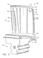
- FIG 2 is a perspective schematic illustration of a turbine part that may be used with gas turbine engine 10 (shown in Figure 1 ).
- Figure 3 is an internal schematic illustration of the turbine part.
- the method is described herein with respect to a turbine rotor blade 40, however the method is not limited to turbine blade 40 but may be utilized on any turbine part.
- a plurality of turbine rotor blades 40 form a high pressure turbine rotor blade stage (not shown) of gas turbine engine 10.
- Each rotor blade 40 includes a hollow airfoil 42 and an integral dovetail 43 used for mounting airfoil 42 to a rotor disk (not shown) in a known manner.
- Airfoil 42 includes a first sidewall 44 and a second sidewall 46.
- First sidewall 44 is convex and defines a suction side of airfoil 42
- second sidewall 46 is concave and defines a pressure side of airfoil 42.
- Sidewalls 44 and 46 are connected at a leading edge 48 and at an axially-spaced trailing edge 50 of airfoil 42 that is downstream from leading edge 48.
- First and second sidewalls 44 and 46 extend longitudinally or radially outward to span from a blade root 52 positioned adjacent dovetail 43 to a tip plate 54 which defines a radially outer boundary of an internal cooling chamber 56.
- Cooling chamber 56 is defined within airfoil 42 between sidewalls 44 and 46. Internal cooling of airfoils 42 is known in the art.
- cooling chamber 56 includes a serpentine passage 58 cooled with compressor bleed air.
- Cooling cavity 56 is in flow communication with a plurality of trailing edge slots 70 which extend longitudinally (axially) along trailing edge 50. Particularly, trailing edge slots 70 extend along pressure sidewall 46 to trailing edge 50.
- Each trailing edge slot 70 includes a recessed wall 72 separated from pressure sidewall 46 by a first sidewall 74 and a second sidewall 76.
- a cooling cavity exit opening 78 extends from cooling cavity 56 to each trailing edge slot 70 adjacent recessed wall 72.
- Each recessed wall 72 extends from trailing edge 50 to cooling cavity exit opening 78.
- a plurality of lands 80 separate each trailing edge slot 70 from an adjacent trailing edge slot 70. Sidewalls 74 and 76 extend from lands 80.
- turbine part 40 is coated by a process 100 to deposit a nickel aluminide (NiAl) coating on the exterior surface of airfoil 42.
- NiAl nickel aluminide
- the nickel aluminide coating is applied to at least a portion of first sidewall 44 and second sidewall 46.
- the nickel aluminide coating is applied 102 to substantially the entire external surface of airfoil 42 to a thickness between approximately 25.4 ⁇ m (0.001 inches (1 mil)) and approximately 76.2 ⁇ m (0.003 inches (3 mils)).
- the nickel aluminide coating is a base coat that is applied 102 to substantially the entire external surface of airfoil 42 to a thickness of approximately 50.8 ⁇ m (0.002 inches (2 mils)).
- the nickel aluminide coating is generally an aluminide bond coat that may include aluminum, nickel, zirconium, and/or chromium.
- the nickel aluminide bond coating is applied to airfoil 42 using a line-of-sight process such as an ion plasma deposition process, electron beam physical deposition (EB-PVD), or any other high energy deposition processes.
- a line-of-sight process such as an ion plasma deposition process, electron beam physical deposition (EB-PVD), or any other high energy deposition processes.
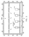
- the externally coated turbine part 40 is then positioned 104 within a vapor phase aluminiding (VPA) chamber 88 of a VPA coating system 90.
- the vapor phase aluminiding system includes the donor alloy pellets of chromium -aluminum, cobalt-aluminum, or nickel-aluminum composition, a halide activator to produce aluminum containing vapors, a source of heat (furnace), and a manifold to flow gases through internal surfaces.
- the donor alloy is a chromium -aluminum composition.
- a temperature within chamber 88 is set between approximately 982°C (1800° Fahrenheit (F)) and approximately 1121°C (2050° F).
- a temperature within chamber 88 is set to approximately 1079°C (1975° F) and the aluminide gases are then generated from the reaction of the chrome-aluminum donor alloy and the halide gased into chamber 88 such that a portion of the aluminum gases is deposited on the external and internal surface of airfoil 42 over a period of time between approximately thirty minutes and approximately four hours, generally approximately two hours.
- the aluminide coating is deposited to a thickness between approximately 12.7 ⁇ m (0.0005 inches (1/2 mil)) and approximately 38.1 ⁇ m (0.0015 inches (1.5 mils)) on the internal surfaces of turbine part 40 with negligible or a very small amount of coating being deposited on the external surface of turbine part 40.
- the chemical composition of the chromium-aluminum donor alloy and the activator are contained in the VPA chamber to produce aluminum halide gases with an activity of aluminum, namely the mole fraction of aluminum in the gases, so that a required aluminum coating is obtained in the internal surfaces while the external nickel aluminide surface remains unchanged in chemical composition, or experiences a minor change in chemical composition.
- the chemical composition of chrome-aluminum donor alloy is about 80 weight percent of chromium and 20 weight percent of aluminum.
- the donor alloy is preferably lower in aluminum composition compared to present conventional practice of using donor alloy of composition between about 30 weight percent aluminum to 50 weight percent aluminum.
- the primary theoretical mechanism includes that the amount of aluminum in the low activity aluminum donor alloy is sufficient to give aluminum to nickel-base alloy whereas the aluminum in the donor alloy is not high enough to transfer additional aluminum to the nickel aluminide bond coat. Due to the preferred composition of the low activity of aluminum in the vapor phase in the aluminum halide gases, the external surface of the turbine part containing the nickel aluminide bond coat remains practically the same as before the vapor phase treatment.
- the aluminum halide activator is between approximately 10.6 and 15.7 g of AlF 3 for 1 m 3 /hr (0.3 and 0.5 grams of AlF3 for 1 cu.ft/hr) of transport gas.
- the transport gases may be hydrogen, helium, nitrogen and argon.
- the most preferred gas is hydrogen.
- the flow of transport gases is designed proportionally to provide aluminiding vapor flow through internal cavities, while simultaneously substantially decreasing the activity of aluminiding gases to obtain equilibrium with the external coating of nickel aluminide.
- the most preferred range of transport gas flow is between approximately 2.8 and 5.7 m 3 /hr (100 and 200 cu.ft/hr).
- the aluminizing process is run for a period of time in the range of about 1 hour to about 10 hours depending on the temperature at which the turbine part is aluminided.
- the time of aluminiding is kept at the low end of this range to lower aluminum activity.
- the time is approximately 2 hours at a temperature of approximately 1975° Fahrenheit (1070° Celsius).
- the above described process 100 provides for coating the external surfaces of turbine part 40 with a protective NiAl coating to protect the external surfaces from corrosion and/or oxidation.
- the NiAl coating is an oxidation resistant bond coat for the electron beam physical vapor deposition (EB-PVD) thermal barrier coating.
- EB-PVD electron beam physical vapor deposition
- the most preferred embodiment of this invention provides the NiAl bond coat under original condition with no degradation in various performance.
- process 100 includes using a VPA system to provide internal aluminiding with an equilibrium activity aluminum vapors such that the external surface of the blade does not get over-aluminided while the internal surfaces of the blade receive a coating that has a desired thickness
Description
- This invention relates generally to gas turbine engines, and more particularly, to methods of depositing protective coatings on components of gas turbine engines.
- Gas turbine engines typically include high and low pressure compressors, a combustor, and at least one turbine. The compressors compress air which is mixed with fuel and channeled to the combustor. The mixture is then ignited for generating hot combustion gases, and the combustion gases are channeled to the turbine which extracts energy from the combustion gases for powering the compressor, as well as producing useful work to propel an aircraft in flight or to power a load, such as an electrical generator.
- The operating environment within a gas turbine engine is both thermally and chemically hostile. Significant advances in high temperature alloys have been achieved through the formulation of iron, nickel and cobalt-base superalloys, though components formed from such alloys often cannot withstand long service exposures if located in certain sections of a gas turbine engine, such as the turbine, combustor and augmentor. A common solution is to provide turbine, combustor and augmentor components with an environmental coating that inhibits oxidation and hot corrosion, or a thermal barrier coating (TBC) system that, in addition to inhibiting oxidation and hot corrosion, also thermally insulates the component surface from its operating environment.
- Coating materials that have found wide use as environmental coatings include diffusion aluminide coatings, which are generally single-layer oxidation-resistant layers formed by a diffusion process, such as pack cementation. Diffusion processes generally entail reacting the surface of a component with an aluminum-containing gas composition to form two distinct zones, the outermost of which is an additive layer containing an environmentally-resistant intermetallic represented by MAl, where M is iron, nickel or cobalt, depending on the substrate material. Beneath the additive layer is a diffusion zone that includes various intermetallic and metastable phases that form during the coating reaction as a result of diffusion gradients and changes in elemental solubility in the local region of the substrate. During high temperature exposure in air, the MA1 intermetallic forms a protective aluminum oxide (alumina) scale or layer that inhibits oxidation of the diffusion coating and the underlying substrate.
- High reliability TBC bond coats consisting of a NiAl overlay coating is highly sensitive to aluminide processing. Aluminide before and/or after the NiAl coating can result in substantial degradation of the TBC cyclic life. However, in order to protect the inside cooling passages from oxidation and hot corrosion, a vapor phase aluminide is required. This cross-functional requirement between external and internal surfaces of a turbine part forces a highly labor intensive and costly process of vapor phase aluminiding (VPA) coating, wax filling of internal passages to protect internals, chemical stripping of aluminide from external surfaces and protecting the internal passages while chemical processing. Additionally, these steps add the risk of chemically attacking the coating deposited on the internal passages.
- Known process technology consists of VPA coating, at about 982°C (1800°F) to about 1093°C (2000°F), the entire blade including both internal and external surfaces, filling inside passages with wax to protect from chemical attack, striping Al from the external surfaces by chemical surface treatment, removing the wax, and heat tint to assure that all aluminide is removed. These process steps can add a cost penalty and about 7-10 days of added manufacturing time.
- The
European patent EP 1 524 328 A1 discloses a method of selected region vapour phase aluminizing by means of control of the processing temperature, activator concentration, time etc with the objective of minimizing the formation of an aluminized surface on the NiAl-coated exterior surfaces. - Various aspects of the invention are set out in the claims.
- In one aspect according to the present invention, a method of forming a metal coating on surfaces on a turbine part is provided. The method includes positioning the turbine part in a VPA chamber, coupling a gas manifold to at least one internal passage inlet, and coating the internal surface and the external surface of the turbine part by a vapor phase aluminiding (VPA) process using metallic coating gases to form an aluminide coating on the internal surfaces of the turbine part and a coating at least partially over the bond coating.
- In another aspect, a method of forming a metal coating on surfaces of internal passages of a turbine part, the turbine part having an outer surface and including at least one internal passage is provided. The method includes applying a highly oxidation resistant nickel aluminide ( NiAl) bond coat to the external surfaces of the turbine part, positioning the blade in VPA coating chamber, placing a source of aluminum in the form of small chunks, introducing a halide compound to form gaseous vapor at higher temperatures, and forming an aluminide coating at both internal surfaces and external surfaces.
- Various aspects and embodiments of the present invention will now be described in connection with the accompanying drawings, in which:
-
Figure 1 is schematic illustration of a gas turbine engine. -
Figure 2 is a perspective schematic illustration of an exemplary turbine rotor blade shown inFigure 1 . -
Figure 3 is an internal schematic illustration of the turbine rotor blade shown inFigure 2 . -
Figure 4 is an internal schematic illustration of the turbine rotor blade shown inFigure 2 coupled to a vapor phase aluminiding manifold. -
Figure 5 is a schematic illustration of a vapor phase aluminiding system. -
Figure 6 is a flow diagram of a method of coating the exemplary turbine rotor blade shown inFigure 2 . - A method of coating the internal and external surfaces of a turbine part, such as a rotor blade for example, with an oxidation resistant coating while maintaining the performance of nickel aluminide coating is described below in detail. The method includes coating the external surfaces of the turbine part with a nickel aluminide coating and utilizing a vapor phase aluminiding process to deposit a protective coating on the internal and external surfaces of the turbine part to protect the turbine part from oxidation and hot corrosion. The uniqueness of the process parameters is designed in such a way so as to provide an equilibrium composition of aluminide vapors with nickel aluminide external surfaces while providing coating to internal surfaces.
- Referring to the drawings,
Figure 1 is a schematic illustration of agas turbine engine 10 that includes afan assembly 12 and acore engine 13 including a high pressure compressor 14, acombustor 16, and ahigh pressure turbine 18.Engine 10 also includes alow pressure turbine 20, and abooster 22.Fan assembly 12 includes an array of fan blades 24 extending radially outward from arotor disc 26.Engine 10 has anintake side 28 and anexhaust side 30. In one embodiment, the gas turbine engine is a GE90 available from General Electric Company, Cincinnati, Ohio.Fan assembly 12 andturbine 20 are coupled by afirst rotor shaft 31, and compressor 14 andturbine 18 are coupled by asecond rotor shaft 32. - During operation, air flows through
fan assembly 12, along acentral axis 34, and compressed air is supplied to high pressure compressor 14. The highly compressed air is delivered tocombustor 16. Airflow (not shown inFigure 1 ) fromcombustor 16drives turbines turbine 20drives fan assembly 12 by way ofshaft 31. -
Figure 2 is a perspective schematic illustration of a turbine part that may be used with gas turbine engine 10 (shown inFigure 1 ).Figure 3 is an internal schematic illustration of the turbine part. In the exemplary embodiment, the method is described herein with respect to aturbine rotor blade 40, however the method is not limited toturbine blade 40 but may be utilized on any turbine part. Referring toFigures 2 and3 , in an exemplary embodiment, a plurality ofturbine rotor blades 40 form a high pressure turbine rotor blade stage (not shown) ofgas turbine engine 10. Eachrotor blade 40 includes ahollow airfoil 42 and anintegral dovetail 43 used for mountingairfoil 42 to a rotor disk (not shown) in a known manner. - Airfoil 42 includes a
first sidewall 44 and asecond sidewall 46.First sidewall 44 is convex and defines a suction side ofairfoil 42, andsecond sidewall 46 is concave and defines a pressure side ofairfoil 42.Sidewalls edge 48 and at an axially-spacedtrailing edge 50 ofairfoil 42 that is downstream from leadingedge 48. - First and
second sidewalls blade root 52 positionedadjacent dovetail 43 to atip plate 54 which defines a radially outer boundary of aninternal cooling chamber 56.Cooling chamber 56 is defined withinairfoil 42 betweensidewalls airfoils 42 is known in the art. In the exemplary embodiment,cooling chamber 56 includes aserpentine passage 58 cooled with compressor bleed air. -
Cooling cavity 56 is in flow communication with a plurality oftrailing edge slots 70 which extend longitudinally (axially) alongtrailing edge 50. Particularly,trailing edge slots 70 extend alongpressure sidewall 46 to trailingedge 50. Eachtrailing edge slot 70 includes arecessed wall 72 separated frompressure sidewall 46 by afirst sidewall 74 and asecond sidewall 76. A coolingcavity exit opening 78 extends fromcooling cavity 56 to eachtrailing edge slot 70 adjacentrecessed wall 72. Eachrecessed wall 72 extends fromtrailing edge 50 to coolingcavity exit opening 78. A plurality oflands 80 separate eachtrailing edge slot 70 from an adjacenttrailing edge slot 70.Sidewalls lands 80. - Referring also to
Figures 4 ,5 , and6 , in the exemplary embodiment, to protect both the internal and external surfaces of the turbine part, e.g.turbine rotor blade 40, from oxidation and hot corrosion,turbine part 40 is coated by aprocess 100 to deposit a nickel aluminide (NiAl) coating on the exterior surface ofairfoil 42. Specifically, the nickel aluminide coating is applied to at least a portion offirst sidewall 44 andsecond sidewall 46. In the exemplary embodiment, the nickel aluminide coating is applied 102 to substantially the entire external surface ofairfoil 42 to a thickness between approximately 25.4 µm (0.001 inches (1 mil)) and approximately 76.2 µm (0.003 inches (3 mils)). In the exemplary embodiment, the nickel aluminide coating is a base coat that is applied 102 to substantially the entire external surface ofairfoil 42 to a thickness of approximately 50.8 µm (0.002 inches (2 mils)). The nickel aluminide coating is generally an aluminide bond coat that may include aluminum, nickel, zirconium, and/or chromium. - In the exemplary embodiment, the nickel aluminide bond coating is applied to
airfoil 42 using a line-of-sight process such as an ion plasma deposition process, electron beam physical deposition (EB-PVD), or any other high energy deposition processes. - The externally coated
turbine part 40 is then positioned 104 within a vapor phase aluminiding (VPA) chamber 88 of a VPA coating system 90. The vapor phase aluminiding system includes the donor alloy pellets of chromium -aluminum, cobalt-aluminum, or nickel-aluminum composition, a halide activator to produce aluminum containing vapors, a source of heat (furnace), and a manifold to flow gases through internal surfaces. - In the exemplary embodiment, the donor alloy is a chromium -aluminum composition. Specifically, a temperature within chamber 88 is set between approximately 982°C (1800° Fahrenheit (F)) and approximately 1121°C (2050° F). In the exemplary embodiment, a temperature within chamber 88 is set to approximately 1079°C (1975° F) and the aluminide gases are then generated from the reaction of the chrome-aluminum donor alloy and the halide gased into chamber 88 such that a portion of the aluminum gases is deposited on the external and internal surface of
airfoil 42 over a period of time between approximately thirty minutes and approximately four hours, generally approximately two hours. In the exemplary embodiment, the aluminide coating is deposited to a thickness between approximately 12.7 µm (0.0005 inches (1/2 mil)) and approximately 38.1 µm (0.0015 inches (1.5 mils)) on the internal surfaces ofturbine part 40 with negligible or a very small amount of coating being deposited on the external surface ofturbine part 40. The chemical composition of the chromium-aluminum donor alloy and the activator are contained in the VPA chamber to produce aluminum halide gases with an activity of aluminum, namely the mole fraction of aluminum in the gases, so that a required aluminum coating is obtained in the internal surfaces while the external nickel aluminide surface remains unchanged in chemical composition, or experiences a minor change in chemical composition. In a more preferred embodiment, the chemical composition of chrome-aluminum donor alloy is about 80 weight percent of chromium and 20 weight percent of aluminum. The donor alloy is preferably lower in aluminum composition compared to present conventional practice of using donor alloy of composition between about 30 weight percent aluminum to 50 weight percent aluminum. The primary theoretical mechanism includes that the amount of aluminum in the low activity aluminum donor alloy is sufficient to give aluminum to nickel-base alloy whereas the aluminum in the donor alloy is not high enough to transfer additional aluminum to the nickel aluminide bond coat. Due to the preferred composition of the low activity of aluminum in the vapor phase in the aluminum halide gases, the external surface of the turbine part containing the nickel aluminide bond coat remains practically the same as before the vapor phase treatment. In the preferred embodiment, the aluminum halide activator (AlF3) is between approximately 10.6 and 15.7 g of AlF3 for 1 m3/hr (0.3 and 0.5 grams of AlF3 for 1 cu.ft/hr) of transport gas. In the preferred embodiment, the transport gases may be hydrogen, helium, nitrogen and argon. The most preferred gas is hydrogen. In the most preferred embodiment, the flow of transport gases is designed proportionally to provide aluminiding vapor flow through internal cavities, while simultaneously substantially decreasing the activity of aluminiding gases to obtain equilibrium with the external coating of nickel aluminide. In the preferred embodiment, it is estimated that the flow of transport gases of five equivalent volume of coating chamber 88 per hour reduces activity of aluminum by about 5 percent. The most preferred range of transport gas flow is between approximately 2.8 and 5.7 m3/hr (100 and 200 cu.ft/hr). - The aluminizing process is run for a period of time in the range of about 1 hour to about 10 hours depending on the temperature at which the turbine part is aluminided. In the preferred embodiment, the time of aluminiding is kept at the low end of this range to lower aluminum activity. In a most preferred process, the time is approximately 2 hours at a temperature of approximately 1975° Fahrenheit (1070° Celsius).
- The above described
process 100 provides for coating the external surfaces ofturbine part 40 with a protective NiAl coating to protect the external surfaces from corrosion and/or oxidation. Furthermore, the NiAl coating is an oxidation resistant bond coat for the electron beam physical vapor deposition ( EB-PVD) thermal barrier coating. The most preferred embodiment of this invention provides the NiAl bond coat under original condition with no degradation in various performance. - Specifically,
process 100 includes using a VPA system to provide internal aluminiding with an equilibrium activity aluminum vapors such that the external surface of the blade does not get over-aluminided while the internal surfaces of the blade receive a coating that has a desired thickness -
- 10
- Gas turbine engine
- 12
- Fan assembly
- 13
- Core engine
- 14
- High pressure compressor
- 16
- Combustor
- 18
- High pressure turbine
- 20
- Low pressure turbine
- 22
- Booster
- 24
- Fan blades
- 26
- Rotor disc
- 28
- Intake side
- 30
- Exhaust side
- 31
- First rotor shaft
- 32
- Second rotor shaft
- 34
- Central axis
- 40
- Turbine part
- 42
- Airfoil
- 43
- Dovetail
- 44
- First sidewall
- 46
- Second sidewall
- 48
- Leading edge
- 50
- Trailing edge
- 52
- Blade root
- 54
- Tip plate
- 56
- Cooling chamber
- 58
- Serpentine passage
- 70
- Trailing edge slot
- 72
- Recessed wall
- 74
- First sidewall
- 76
- Second sidewall
- 78
- Cooling cavity exit opening
- 80
- Lands
- 88
- Vapor phase aluminiding (VPA) chamber
- 90
- VPA coating system
- 100
- Process provides for coating the external surface
- 102
- Applying a nickel aluminum (NiAl) coating to substantially the entire external surface of airfoil
- 104
- Positioning the turbine blade in a vapor phase aluminiding (VPA) Chamber
Claims (5)
- A method of forming a metal coating on surfaces of internal passages of a turbine part (40), the turbine part having an outer surface and comprising at least one internal passage, said method comprising:applying a nickel aluminide bond coating to an external surface of the turbine part;positioning the turbine part in a VPA chamber (88);coupling a gas manifold to at least one internal passage inlet;exposing the turbine part to a low activity chromium and aluminum donor alloy composition including chromium and aluminum, the composition including between approximately ten weight percent aluminum and approximately twenty four weight percent aluminum; andcoating the internal surface of the turbine part by a vapor phase aluminiding (VPA) process to form a nickel aluminide coating on the internal surface.
- A method in accordance with Claim 1 wherein the coating is formed at the internal surface by reaction of aluminum halide gases with the metal surface.
- A method in accordance with any preceding Claim further comprising heat treating the metal coating at 1038 °C (1900°F) to 1121°C (2050°F) for about 30 minutes to about 4 hours.
- A method in accordance with any preceding Claim further comprising applying a bond coating between approximately 25.4µm (0.001 inches) and approximately 76.2µm (0.003 inches) in thickness to the external surface of the turbine part (40).
- A method in accordance with any preceding Claim further comprising applying an aluminum coating between approximately 12.7µm (0.0005 inches) and approximately 38.1µm (0.0015 inches) in thickness to at least a portion of the internal surface of the turbine part (40).
Applications Claiming Priority (1)
| Application Number | Priority Date | Filing Date | Title |
|---|---|---|---|
| US11/354,363 US20070190245A1 (en) | 2006-02-15 | 2006-02-15 | Method of coating gas turbine components |
Publications (2)
| Publication Number | Publication Date |
|---|---|
| EP1820876A1 EP1820876A1 (en) | 2007-08-22 |
| EP1820876B1 true EP1820876B1 (en) | 2011-07-13 |
Family
ID=37986871
Family Applications (1)
| Application Number | Title | Priority Date | Filing Date |
|---|---|---|---|
| EP07101752A Expired - Fee Related EP1820876B1 (en) | 2006-02-15 | 2007-02-05 | Method of coating gas turbine components |
Country Status (7)
| Country | Link |
|---|---|
| US (1) | US20070190245A1 (en) |
| EP (1) | EP1820876B1 (en) |
| JP (1) | JP2007218261A (en) |
| CN (1) | CN101021001A (en) |
| BR (1) | BRPI0700671A (en) |
| CA (1) | CA2576572A1 (en) |
| SG (2) | SG135115A1 (en) |
Families Citing this family (11)
| Publication number | Priority date | Publication date | Assignee | Title |
|---|---|---|---|---|
| FR2921937B1 (en) * | 2007-10-03 | 2009-12-04 | Snecma | METHOD FOR STEAM PHASE ALUMINIZATION OF A TURBOMACHINE METAL PIECE |
| FR2924129B1 (en) * | 2007-11-27 | 2010-08-27 | Snecma Services | PROCESS FOR REALIZING A MODIFIED NICKEL ALUMINUM COATING PLATINUM SINGLE PHASE |
| US20100159136A1 (en) * | 2008-12-19 | 2010-06-24 | Rolls-Royce Corporation | STATIC CHEMICAL VAPOR DEPOSITION OF y-Ni + y'-Ni3AI COATINGS |
| US9587645B2 (en) * | 2010-09-30 | 2017-03-07 | Pratt & Whitney Canada Corp. | Airfoil blade |
| US9429029B2 (en) | 2010-09-30 | 2016-08-30 | Pratt & Whitney Canada Corp. | Gas turbine blade and method of protecting same |
| US9427835B2 (en) | 2012-02-29 | 2016-08-30 | Pratt & Whitney Canada Corp. | Nano-metal coated vane component for gas turbine engines and method of manufacturing same |
| US10100650B2 (en) | 2012-06-30 | 2018-10-16 | General Electric Company | Process for selectively producing thermal barrier coatings on turbine hardware |
| US9771644B2 (en) * | 2013-11-08 | 2017-09-26 | Praxair S.T. Technology, Inc. | Method and apparatus for producing diffusion aluminide coatings |
| CN103993258B (en) * | 2014-05-21 | 2017-01-25 | 昆山海普电子材料有限公司 | Method for coating workpiece with complex inner cavity structure |
| US10030298B2 (en) | 2015-08-21 | 2018-07-24 | General Electric Company | Method for altering metal surfaces |
| CN109182689A (en) * | 2018-11-14 | 2019-01-11 | 中国航发动力股份有限公司 | A kind of axle journal class precision forged blade fixture of heat treatment and heat treatment process |
Family Cites Families (18)
| Publication number | Priority date | Publication date | Assignee | Title |
|---|---|---|---|---|
| US5236745A (en) * | 1991-09-13 | 1993-08-17 | General Electric Company | Method for increasing the cyclic spallation life of a thermal barrier coating |
| US5419971A (en) * | 1993-03-03 | 1995-05-30 | General Electric Company | Enhanced thermal barrier coating system |
| DE19607625C1 (en) * | 1996-02-29 | 1996-12-12 | Mtu Muenchen Gmbh | Preparing and/or coating surfaces of hollow components |
| US5723078A (en) * | 1996-05-24 | 1998-03-03 | General Electric Company | Method for repairing a thermal barrier coating |
| US5817371A (en) * | 1996-12-23 | 1998-10-06 | General Electric Company | Thermal barrier coating system having an air plasma sprayed bond coat incorporating a metal diffusion, and method therefor |
| US5807428A (en) * | 1997-05-22 | 1998-09-15 | United Technologies Corporation | Slurry coating system |
| US6555179B1 (en) * | 1998-01-14 | 2003-04-29 | General Electric Company | Aluminizing process for plasma-sprayed bond coat of a thermal barrier coating system |
| US6168874B1 (en) * | 1998-02-02 | 2001-01-02 | General Electric Company | Diffusion aluminide bond coat for a thermal barrier coating system and method therefor |
| US6146696A (en) * | 1999-05-26 | 2000-11-14 | General Electric Company | Process for simultaneously aluminizing nickel-base and cobalt-base superalloys |
| US6273678B1 (en) * | 1999-08-11 | 2001-08-14 | General Electric Company | Modified diffusion aluminide coating for internal surfaces of gas turbine components |
| US6863925B1 (en) * | 2000-09-26 | 2005-03-08 | General Electric Company | Method for vapor phase aluminiding including a modifying element |
| US6434823B1 (en) * | 2000-10-10 | 2002-08-20 | General Electric Company | Method for repairing a coated article |
| US6465040B2 (en) * | 2001-02-06 | 2002-10-15 | General Electric Company | Method for refurbishing a coating including a thermally grown oxide |
| US7026011B2 (en) * | 2003-02-04 | 2006-04-11 | General Electric Company | Aluminide coating of gas turbine engine blade |
| US6929825B2 (en) * | 2003-02-04 | 2005-08-16 | General Electric Company | Method for aluminide coating of gas turbine engine blade |
| US20040180232A1 (en) * | 2003-03-12 | 2004-09-16 | General Electric Company | Selective region vapor phase aluminided superalloy articles |
| EP1524328B1 (en) * | 2003-10-15 | 2017-01-04 | General Electric Company | Method of selective region vapor phase aluminizing |
| US7163718B2 (en) * | 2003-10-15 | 2007-01-16 | General Electric Company | Method of selective region vapor phase aluminizing |
-
2006
- 2006-02-15 US US11/354,363 patent/US20070190245A1/en not_active Abandoned
-
2007
- 2007-02-01 CA CA002576572A patent/CA2576572A1/en not_active Abandoned
- 2007-02-05 EP EP07101752A patent/EP1820876B1/en not_active Expired - Fee Related
- 2007-02-09 SG SG200700976-4A patent/SG135115A1/en unknown
- 2007-02-09 SG SG200905188-9A patent/SG155184A1/en unknown
- 2007-02-13 BR BRPI0700671-3A patent/BRPI0700671A/en not_active IP Right Cessation
- 2007-02-15 CN CNA2007100059611A patent/CN101021001A/en active Pending
- 2007-02-15 JP JP2007034518A patent/JP2007218261A/en active Pending
Also Published As
| Publication number | Publication date |
|---|---|
| CN101021001A (en) | 2007-08-22 |
| BRPI0700671A (en) | 2007-11-06 |
| SG135115A1 (en) | 2007-09-28 |
| US20070190245A1 (en) | 2007-08-16 |
| JP2007218261A (en) | 2007-08-30 |
| EP1820876A1 (en) | 2007-08-22 |
| CA2576572A1 (en) | 2007-08-15 |
| SG155184A1 (en) | 2009-09-30 |
Similar Documents
| Publication | Publication Date | Title |
|---|---|---|
| EP1820876B1 (en) | Method of coating gas turbine components | |
| US6616969B2 (en) | Apparatus and method for selectively coating internal and external surfaces of an airfoil | |
| US6440496B1 (en) | Method of forming a diffusion aluminide coating | |
| US6283714B1 (en) | Protection of internal and external surfaces of gas turbine airfoils | |
| US6993811B2 (en) | System for applying a diffusion aluminide coating on a selective area of a turbine engine component | |
| EP1079073B1 (en) | Modified diffusion aluminide coating for internal surfaces of gas turbine components | |
| EP3049547B1 (en) | Method of simultaneously applying three different diffusion aluminide coatings to a single part | |
| US7838070B2 (en) | Method of coating gas turbine components | |
| EP1801353A2 (en) | Method of coating internal passages of gas turbine components | |
| US6905730B2 (en) | Aluminide coating of turbine engine component | |
| EP1634977A1 (en) | Process for inhibiting the formation of a secondary reaction zone (SRZ) and coating system therefor | |
| US6326057B1 (en) | Vapor phase diffusion aluminide process | |
| EP2435595A1 (en) | Layered coating system with a mcralx layer and a chromium rich layer and a method to produce it | |
| US7163718B2 (en) | Method of selective region vapor phase aluminizing | |
| EP1411148A1 (en) | Method of depositing a MCrALY-coating on an article and the coated article | |
| US20040180232A1 (en) | Selective region vapor phase aluminided superalloy articles | |
| EP1524328B1 (en) | Method of selective region vapor phase aluminizing | |
| US6896488B2 (en) | Bond coat process for thermal barrier coating | |
| EP1870492A1 (en) | Metal phosphate coating for oxidation resistance | |
| US20070134418A1 (en) | Method for depositing an aluminum-containing layer onto an article | |
| US6630199B1 (en) | Ceramic layer produced by reacting a ceramic precursor with a reactive gas | |
| CA2483232C (en) | Method of selective region vapor phase aluminizing | |
| CA1339403C (en) | Thermal barrier coating for superalloy components | |
| US20080182026A1 (en) | Reactive element-modified aluminide coating for gas turbine airfoils |
Legal Events
| Date | Code | Title | Description |
|---|---|---|---|
| PUAI | Public reference made under article 153(3) epc to a published international application that has entered the european phase |
Free format text: ORIGINAL CODE: 0009012 |
|
| AK | Designated contracting states |
Kind code of ref document: A1 Designated state(s): AT BE BG CH CY CZ DE DK EE ES FI FR GB GR HU IE IS IT LI LT LU LV MC NL PL PT RO SE SI SK TR |
|
| AX | Request for extension of the european patent |
Extension state: AL BA HR MK YU |
|
| 17P | Request for examination filed |
Effective date: 20080222 |
|
| AKX | Designation fees paid |
Designated state(s): DE FR GB IT |
|
| 17Q | First examination report despatched |
Effective date: 20080407 |
|
| GRAP | Despatch of communication of intention to grant a patent |
Free format text: ORIGINAL CODE: EPIDOSNIGR1 |
|
| GRAS | Grant fee paid |
Free format text: ORIGINAL CODE: EPIDOSNIGR3 |
|
| GRAA | (expected) grant |
Free format text: ORIGINAL CODE: 0009210 |
|
| AK | Designated contracting states |
Kind code of ref document: B1 Designated state(s): DE FR GB IT |
|
| REG | Reference to a national code |
Ref country code: GB Ref legal event code: FG4D |
|
| REG | Reference to a national code |
Ref country code: DE Ref legal event code: R096 Ref document number: 602007015728 Country of ref document: DE Effective date: 20110908 |
|
| PGFP | Annual fee paid to national office [announced via postgrant information from national office to epo] |
Ref country code: FR Payment date: 20120306 Year of fee payment: 6 |
|
| PLBE | No opposition filed within time limit |
Free format text: ORIGINAL CODE: 0009261 |
|
| STAA | Information on the status of an ep patent application or granted ep patent |
Free format text: STATUS: NO OPPOSITION FILED WITHIN TIME LIMIT |
|
| PGFP | Annual fee paid to national office [announced via postgrant information from national office to epo] |
Ref country code: DE Payment date: 20120228 Year of fee payment: 6 |
|
| 26N | No opposition filed |
Effective date: 20120416 |
|
| PGFP | Annual fee paid to national office [announced via postgrant information from national office to epo] |
Ref country code: GB Payment date: 20120224 Year of fee payment: 6 Ref country code: IT Payment date: 20120223 Year of fee payment: 6 |
|
| REG | Reference to a national code |
Ref country code: DE Ref legal event code: R097 Ref document number: 602007015728 Country of ref document: DE Effective date: 20120416 |
|
| GBPC | Gb: european patent ceased through non-payment of renewal fee |
Effective date: 20130205 |
|
| REG | Reference to a national code |
Ref country code: FR Ref legal event code: ST Effective date: 20131031 |
|
| REG | Reference to a national code |
Ref country code: DE Ref legal event code: R119 Ref document number: 602007015728 Country of ref document: DE Effective date: 20130903 |
|
| PG25 | Lapsed in a contracting state [announced via postgrant information from national office to epo] |
Ref country code: IT Free format text: LAPSE BECAUSE OF NON-PAYMENT OF DUE FEES Effective date: 20130205 |
|
| PG25 | Lapsed in a contracting state [announced via postgrant information from national office to epo] |
Ref country code: DE Free format text: LAPSE BECAUSE OF NON-PAYMENT OF DUE FEES Effective date: 20130903 Ref country code: FR Free format text: LAPSE BECAUSE OF NON-PAYMENT OF DUE FEES Effective date: 20130228 Ref country code: GB Free format text: LAPSE BECAUSE OF NON-PAYMENT OF DUE FEES Effective date: 20130205 |