EP3539833A1 - Brake system - Google Patents
Brake system Download PDFInfo
- Publication number
- EP3539833A1 EP3539833A1 EP17869974.0A EP17869974A EP3539833A1 EP 3539833 A1 EP3539833 A1 EP 3539833A1 EP 17869974 A EP17869974 A EP 17869974A EP 3539833 A1 EP3539833 A1 EP 3539833A1
- Authority
- EP
- European Patent Office
- Prior art keywords
- signal
- frequency
- control valve
- proportional control
- brake
- Prior art date
- Legal status (The legal status is an assumption and is not a legal conclusion. Google has not performed a legal analysis and makes no representation as to the accuracy of the status listed.)
- Withdrawn
Links
- 230000007274 generation of a signal involved in cell-cell signaling Effects 0.000 claims description 16
- 238000004364 calculation method Methods 0.000 claims description 2
- 238000010586 diagram Methods 0.000 description 8
- 230000007423 decrease Effects 0.000 description 4
- 230000006870 function Effects 0.000 description 4
- 230000000052 comparative effect Effects 0.000 description 3
- 230000003213 activating effect Effects 0.000 description 2
- 238000000034 method Methods 0.000 description 2
- 238000004590 computer program Methods 0.000 description 1
- 230000002349 favourable effect Effects 0.000 description 1
- 238000011144 upstream manufacturing Methods 0.000 description 1
Images




Classifications
-
- B—PERFORMING OPERATIONS; TRANSPORTING
- B60—VEHICLES IN GENERAL
- B60T—VEHICLE BRAKE CONTROL SYSTEMS OR PARTS THEREOF; BRAKE CONTROL SYSTEMS OR PARTS THEREOF, IN GENERAL; ARRANGEMENT OF BRAKING ELEMENTS ON VEHICLES IN GENERAL; PORTABLE DEVICES FOR PREVENTING UNWANTED MOVEMENT OF VEHICLES; VEHICLE MODIFICATIONS TO FACILITATE COOLING OF BRAKES
- B60T7/00—Brake-action initiating means
- B60T7/12—Brake-action initiating means for automatic initiation; for initiation not subject to will of driver or passenger
- B60T7/22—Brake-action initiating means for automatic initiation; for initiation not subject to will of driver or passenger initiated by contact of vehicle, e.g. bumper, with an external object, e.g. another vehicle, or by means of contactless obstacle detectors mounted on the vehicle
-
- B—PERFORMING OPERATIONS; TRANSPORTING
- B60—VEHICLES IN GENERAL
- B60T—VEHICLE BRAKE CONTROL SYSTEMS OR PARTS THEREOF; BRAKE CONTROL SYSTEMS OR PARTS THEREOF, IN GENERAL; ARRANGEMENT OF BRAKING ELEMENTS ON VEHICLES IN GENERAL; PORTABLE DEVICES FOR PREVENTING UNWANTED MOVEMENT OF VEHICLES; VEHICLE MODIFICATIONS TO FACILITATE COOLING OF BRAKES
- B60T8/00—Arrangements for adjusting wheel-braking force to meet varying vehicular or ground-surface conditions, e.g. limiting or varying distribution of braking force
- B60T8/32—Arrangements for adjusting wheel-braking force to meet varying vehicular or ground-surface conditions, e.g. limiting or varying distribution of braking force responsive to a speed condition, e.g. acceleration or deceleration
- B60T8/34—Arrangements for adjusting wheel-braking force to meet varying vehicular or ground-surface conditions, e.g. limiting or varying distribution of braking force responsive to a speed condition, e.g. acceleration or deceleration having a fluid pressure regulator responsive to a speed condition
- B60T8/341—Systems characterised by their valves
- B60T8/342—Pneumatic systems
-
- B—PERFORMING OPERATIONS; TRANSPORTING
- B60—VEHICLES IN GENERAL
- B60T—VEHICLE BRAKE CONTROL SYSTEMS OR PARTS THEREOF; BRAKE CONTROL SYSTEMS OR PARTS THEREOF, IN GENERAL; ARRANGEMENT OF BRAKING ELEMENTS ON VEHICLES IN GENERAL; PORTABLE DEVICES FOR PREVENTING UNWANTED MOVEMENT OF VEHICLES; VEHICLE MODIFICATIONS TO FACILITATE COOLING OF BRAKES
- B60T13/00—Transmitting braking action from initiating means to ultimate brake actuator with power assistance or drive; Brake systems incorporating such transmitting means, e.g. air-pressure brake systems
- B60T13/10—Transmitting braking action from initiating means to ultimate brake actuator with power assistance or drive; Brake systems incorporating such transmitting means, e.g. air-pressure brake systems with fluid assistance, drive, or release
- B60T13/24—Transmitting braking action from initiating means to ultimate brake actuator with power assistance or drive; Brake systems incorporating such transmitting means, e.g. air-pressure brake systems with fluid assistance, drive, or release the fluid being gaseous
- B60T13/26—Compressed-air systems
- B60T13/36—Compressed-air systems direct, i.e. brakes applied directly by compressed air
-
- B—PERFORMING OPERATIONS; TRANSPORTING
- B60—VEHICLES IN GENERAL
- B60T—VEHICLE BRAKE CONTROL SYSTEMS OR PARTS THEREOF; BRAKE CONTROL SYSTEMS OR PARTS THEREOF, IN GENERAL; ARRANGEMENT OF BRAKING ELEMENTS ON VEHICLES IN GENERAL; PORTABLE DEVICES FOR PREVENTING UNWANTED MOVEMENT OF VEHICLES; VEHICLE MODIFICATIONS TO FACILITATE COOLING OF BRAKES
- B60T8/00—Arrangements for adjusting wheel-braking force to meet varying vehicular or ground-surface conditions, e.g. limiting or varying distribution of braking force
- B60T8/17—Using electrical or electronic regulation means to control braking
-
- B—PERFORMING OPERATIONS; TRANSPORTING
- B60—VEHICLES IN GENERAL
- B60T—VEHICLE BRAKE CONTROL SYSTEMS OR PARTS THEREOF; BRAKE CONTROL SYSTEMS OR PARTS THEREOF, IN GENERAL; ARRANGEMENT OF BRAKING ELEMENTS ON VEHICLES IN GENERAL; PORTABLE DEVICES FOR PREVENTING UNWANTED MOVEMENT OF VEHICLES; VEHICLE MODIFICATIONS TO FACILITATE COOLING OF BRAKES
- B60T2201/00—Particular use of vehicle brake systems; Special systems using also the brakes; Special software modules within the brake system controller
- B60T2201/02—Active or adaptive cruise control system; Distance control
- B60T2201/022—Collision avoidance systems
-
- F—MECHANICAL ENGINEERING; LIGHTING; HEATING; WEAPONS; BLASTING
- F15—FLUID-PRESSURE ACTUATORS; HYDRAULICS OR PNEUMATICS IN GENERAL
- F15B—SYSTEMS ACTING BY MEANS OF FLUIDS IN GENERAL; FLUID-PRESSURE ACTUATORS, e.g. SERVOMOTORS; DETAILS OF FLUID-PRESSURE SYSTEMS, NOT OTHERWISE PROVIDED FOR
- F15B2211/00—Circuits for servomotor systems
- F15B2211/50—Pressure control
- F15B2211/51—Pressure control characterised by the positions of the valve element
- F15B2211/513—Pressure control characterised by the positions of the valve element the positions being continuously variable, e.g. as realised by proportional valves
-
- F—MECHANICAL ENGINEERING; LIGHTING; HEATING; WEAPONS; BLASTING
- F15—FLUID-PRESSURE ACTUATORS; HYDRAULICS OR PNEUMATICS IN GENERAL
- F15B—SYSTEMS ACTING BY MEANS OF FLUIDS IN GENERAL; FLUID-PRESSURE ACTUATORS, e.g. SERVOMOTORS; DETAILS OF FLUID-PRESSURE SYSTEMS, NOT OTHERWISE PROVIDED FOR
- F15B2211/00—Circuits for servomotor systems
- F15B2211/50—Pressure control
- F15B2211/52—Pressure control characterised by the type of actuation
- F15B2211/526—Pressure control characterised by the type of actuation electrically or electronically
-
- F—MECHANICAL ENGINEERING; LIGHTING; HEATING; WEAPONS; BLASTING
- F15—FLUID-PRESSURE ACTUATORS; HYDRAULICS OR PNEUMATICS IN GENERAL
- F15B—SYSTEMS ACTING BY MEANS OF FLUIDS IN GENERAL; FLUID-PRESSURE ACTUATORS, e.g. SERVOMOTORS; DETAILS OF FLUID-PRESSURE SYSTEMS, NOT OTHERWISE PROVIDED FOR
- F15B2211/00—Circuits for servomotor systems
- F15B2211/60—Circuit components or control therefor
- F15B2211/63—Electronic controllers
- F15B2211/6303—Electronic controllers using input signals
- F15B2211/6306—Electronic controllers using input signals representing a pressure
-
- F—MECHANICAL ENGINEERING; LIGHTING; HEATING; WEAPONS; BLASTING
- F15—FLUID-PRESSURE ACTUATORS; HYDRAULICS OR PNEUMATICS IN GENERAL
- F15B—SYSTEMS ACTING BY MEANS OF FLUIDS IN GENERAL; FLUID-PRESSURE ACTUATORS, e.g. SERVOMOTORS; DETAILS OF FLUID-PRESSURE SYSTEMS, NOT OTHERWISE PROVIDED FOR
- F15B2211/00—Circuits for servomotor systems
- F15B2211/60—Circuit components or control therefor
- F15B2211/665—Methods of control using electronic components
- F15B2211/6653—Pressure control
-
- F—MECHANICAL ENGINEERING; LIGHTING; HEATING; WEAPONS; BLASTING
- F15—FLUID-PRESSURE ACTUATORS; HYDRAULICS OR PNEUMATICS IN GENERAL
- F15B—SYSTEMS ACTING BY MEANS OF FLUIDS IN GENERAL; FLUID-PRESSURE ACTUATORS, e.g. SERVOMOTORS; DETAILS OF FLUID-PRESSURE SYSTEMS, NOT OTHERWISE PROVIDED FOR
- F15B2211/00—Circuits for servomotor systems
- F15B2211/80—Other types of control related to particular problems or conditions
- F15B2211/88—Control measures for saving energy
-
- F—MECHANICAL ENGINEERING; LIGHTING; HEATING; WEAPONS; BLASTING
- F16—ENGINEERING ELEMENTS AND UNITS; GENERAL MEASURES FOR PRODUCING AND MAINTAINING EFFECTIVE FUNCTIONING OF MACHINES OR INSTALLATIONS; THERMAL INSULATION IN GENERAL
- F16K—VALVES; TAPS; COCKS; ACTUATING-FLOATS; DEVICES FOR VENTING OR AERATING
- F16K31/00—Actuating devices; Operating means; Releasing devices
- F16K31/02—Actuating devices; Operating means; Releasing devices electric; magnetic
- F16K31/06—Actuating devices; Operating means; Releasing devices electric; magnetic using a magnet, e.g. diaphragm valves, cutting off by means of a liquid
Definitions
- the present invention relates to a brake system including an electronic control-type proportional control valve arranged on a pneumatic circuit of an air brake.
- An air brake is employed for a brake system of a large automobile such as a truck in order to produce a larger braking force.
- the compressed air compressed by a compressor driven by the power of the engine is stored in the air tank, and the stored compressed air is supplied to the brake booster, thereby activating the brake.
- Patent Document 1 describes a recent example of a brake system including an air brake. When it is determined that the automobile is highly likely to collide with a front obstacle, the brake system functions to support avoidance of the collision by automatically activating the brake.
- the example of the brake system having such a function includes a first passage and a second passage that serve as supply passages for compressed air from the air tank to the brake booster.
- the first passage includes a brake valve that opens when the brake pedal is operated.
- the second passage includes an electronic control-type proportional control valve of which the open degree varies in a linear manner depending on the level of a drive current.
- the proportional control valve is controlled by a controller. When the controller determines that the collision is highly likely to occur, the controller causes the proportional control valve to open, thereby supplying compressed air through the second passage to the brake booster.
- the pressure of the compressed air supplied to the brake booster is increased by increasing the opening degree of the proportional control valve as the distance of the obstacle becomes closer.
- Patent Document 1 Japanese Laid-Open Patent Publication No. 2009-149111
- the proportional control valve has a characteristic in which the pressure of compressed air, which is an output value, differs depending on the directivity of an input value applied to the proportional control valve. This characteristic is referred to as hysteresis.
- the controller may control the proportional control valve in addition to other devices such as a hydraulic device.
- the controller is normally designed to generate a signal having a high frequency of 1 kHz or higher, which is favorable for controlling a hydraulic device, and output the generated high-frequency signal.
- the high-frequency signal tends to increase the hysteresis of the proportional control valve.
- the above-described brake system is required to reduce the hysteresis even if the high-frequency signal is generated as a signal to the proportional control valve.
- a brake system includes an air tank that stores compressed air, a brake booster configured to activate a brake when supplied with the compressed air, and a pneumatic circuit including a first passage that supplies the compressed air from the air tank to the brake booster.
- the first passage includes a brake valve of which an opening degree is controlled in accordance with a depression amount of a brake pedal.
- the pneumatic circuit also includes a second passage that supplies the compressed air from the air tank to the brake booster.
- the second passage includes a proportional control valve of which an opening degree is controlled through electronic control.
- the brake system also includes a control unit configured to control the proportional control valve.
- the control unit includes a first signal generator configured to generate a first signal.
- the first signal is a pulse signal having a first frequency and indicates a drive amount of the proportional control valve.
- the control unit also includes a second signal generator configured to generate a second signal.
- the second signal is a pulse signal having a second frequency, which is less than or equal to one-tenth of the first frequency
- the control unit further includes a third signal generator configured to generate a command signal for the proportional control valve by multiplying the first signal by the second signal.
- a brake system according to a first embodiment will now be described with reference to Figs. 1 to 6 .
- a pneumatic circuit 10A of a brake system 10 includes an air tank 11 that stores compressed air compressed by a compressor driven by the engine. When the compressed air in the air tank 11 is supplied to a brake booster 12, the brake is activated.
- the pneumatic circuit 10A includes a first passage 13 and a second passage 14 that serve as supply passages through which compressed air in the air tank 11 is supplied to the brake booster 12.
- the first passage 13 includes a first supply passage 15 connected to the air tank 11 and a brake valve 16 arranged on the first supply passage 15.
- the brake valve 16 controls the pressure of compressed air supplied to the brake booster 12 in accordance with the depression amount of the brake pedal operated by a driver.
- the brake valve 16 supplies compressed air having a higher pressure to the brake booster 12 as the depression amount of the brake pedal becomes larger.
- the second passage 14 includes a second supply passage 17 and a proportional control valve 18.
- the second supply passage 17 is connected to the air tank 11 via a part of the first supply passage 15 located upstream of the brake valve 16.
- the proportional control valve 18 is arranged on the second supply passage 17.
- the proportional control valve 18 is an electronic control-type proportional control valve controlled by a controller 30. As the opening degree of the proportional control valve 18 increases, the pressure of compressed air supplied to the brake booster 12 increases.
- the controller 30 determines whether the possibility of the vehicle colliding with a front obstacle detected by a millimeter wave radar is high or low based on various types of information such as the vehicle speed and the distance to the obstacle detected by the millimeter wave rader.
- the controller 30 When determining that the possibility of the collision is high, the controller 30 opens the proportional control valve 18. Further, the controller 30 controls the opening degree of the proportional control valve 18 such that the pressure of compressed air supplied to the brake booster 12 becomes higher as the distance to the obstacle becomes closer.
- the first supply passage 15 and the second supply passage 17 may be connected to the air tank 11 independently from each other.
- the pneumatic circuit 10A includes a shuttle valve 19.
- the shuttle valve 19 includes an inlet to which the first supply passage 15 is connected and another inlet to which the second supply passage 17 is connected.
- the shuttle valve 19 supplies, to the brake booster 12 through a common passage 20, the higher-pressure one of the compressed air supplied from the first supply passage 15 and the compressed air supplied from the second supply passage 17.
- the compressed air flows from the air tank 11 into the first supply passage 15, passes through the brake valve 16, and then flows into the shuttle valve 19.
- the compressed air flows from the air tank 11 into the second supply passage 17, passes through the proportional control valve 18, and then flows into the shuttle valve 19.
- compressed air flows from the shuttle valve 19 through the common passage 20 to the brake booster 12.
- the brake system 10 includes a pressure sensor 26 located in the common passage 20, which connects the shuttle valve 19 to the brake booster 12.
- the pressure sensor 26 detects a pressure Pa of compressed air flowing through the common passage 20.
- the pressure sensor 26 outputs a signal indicating the detected pressure Pa to the controller 30.
- the brake system 10 includes a current sensor 28 located in a circuit that supplies a power of a supply voltage Vo from the controller 30 to the proportional control valve 18.
- the current sensor 28 detects a drive current value Ia of the proportional control valve 18.
- the current sensor 28 outputs a signal indicating the detected drive current value Ia to the controller 30.
- the controller 30 is powered by a power supply 29 to control the proportional control valve 18.
- the controller 30 that controls the proportional control valve 18 will now be described with reference to Figs. 2 to 6 .
- the controller 30 is configured mainly by an electronic control unit (ECU) 31 and includes the ECU 31 and a command signal generation unit 32.
- the controller 30 may include a microcomputer and/or a dedicated hardware (application specific integrated circuit; ASIC) that executes at least some of various types of processes. That is, the ECU 50 may be configured by circuitry including 1) one or more processors (microcomputers) running on computer programs (software), 2) one or more dedicated hardware circuits such as ASIC, or 3) a combination thereof.
- the ECU 31 includes for example, a processor 33, a memory 34, an input interface 35, and an output interface 36 that are connected to one another by a bus 37.
- the ECU 31 obtains signals from the pressure sensor 26 and the current sensor 28 via the input interface 35.
- the ECU 31 executes various types of processes based on a program and various types of data stored in the memory 34 as well as the pressure Pa and the drive current value Ia received from the sensors 26 and 28, and the ECU 31 outputs a first signal, which indicates the drive amount of the proportional control valve 18, to the command signal generation unit 32 via the output interface 36.
- the command signal generation unit 32 generates a command signal Sc based on the first signal and applies the generated command signal Sc to the proportional control valve 18.
- the ECU 31 includes, as various types of functional units, a target pressure calculator 41, a target current calculator 42, an LPF unit 43, a first subtractor 44, a PID unit 45, a second subtractor 46, a carrier wave generator 47, and a comparator 48.
- the target pressure calculator 41 calculates a target pressure Ptrg, which is the pressure of compressed air supplied to the brake booster 12, based on, for example, the vehicle speed and the distance to an obstacle. Then, the target pressure calculator 41 outputs a target pressure signal S1, which indicates the target pressure Ptrg, to the target current calculator 42.
- the target current calculator 42 calculates a target current value Itrg, which is a target value of the drive current of the proportional control valve 18, based on the target pressure Ptrg and a target current table 49 stored in the memory 34.
- the target current table 49 defines the target current value Itrg such that the target current value Itrg increases as the target pressure Ptrg increases.
- the target current calculator 42 outputs a target current signal S2, which indicates the calculated target current value Itrg.
- the LPF (Low Pass Filter) unit 43 eliminates a high-frequency component included in a signal from the current sensor 28 and outputs a drive current signal S3, which indicates the drive current value Ia of the proportional control valve 18, to the first subtractor 44.
- the first subtractor 44 calculates a difference ⁇ I between the target current value Itrg, which is indicated by the target current signal S2, and the drive current value la, which is indicated by the drive current signal S3. Then, the first subtractor 44 outputs a difference signal S4, which indicates the difference ⁇ I, to the PID unit 45.
- the PID (Proportional Integral Differential) unit 45 calculates a correction value Ic used to correct the target current value Itrg based on the difference ⁇ I, which is calculated by the first subtractor 44.
- the correction value Ic is the sum of a proportional term used to perform proportional control based on the difference ⁇ I, an integral term used to perform integral control based on the difference ⁇ I, and a differential term used to perform differential control based on the difference ⁇ I.
- the PID unit 45 outputs a correction signal S5, which indicates the correction value Ic, to the second subtractor 46.
- the second subtractor 46 subtracts the correction value Ic, which is indicated by the correction signal S5, from the target current value Itrg, which is indicated by the target current signal S2. Then, the second subtractor 46 calculates a drive current value lat, which is the drive amount of the proportional control valve 18 suitable for achieving the target pressure Ptrg, as a determination value Vj.
- the determination value Vj is used to generate a first signal Sb1, which serves as a base for generating the command signal Sc.
- the second subtractor 46 outputs a determination signal S6, which indicates the determination value Vj, to the comparator 48.
- the target pressure calculator 41, the target current calculator 42, the LPF unit 43, the first subtractor 44, the PID unit 45, and the second subtractor 46 configure a drive amount calculation unit.
- the carrier wave generator 47 generates a carrier wave such as a triangle wave and a sawtooth wave.
- the carrier wave generator 47 of the present embodiment generates a triangle wave to generate the first signal Sb1 and outputs a triangle wave signal S7, which is the generated triangle wave, to the comparator 48.
- a triangle wave frequency f1 is set to a frequency of 1 kHz or higher, which is higher than a frequency f2 of a second signal generated by a second signal generator 52 (described later).
- the frequency f1 is set to 1650 Hz.
- the frequency f1 corresponds to a first frequency and is used by the ECU 31 when generating a command signal to other devices suitable for control at a frequency of 1 kHz or higher, such as a hydraulic device. It is preferred that the frequency f1 be greater than or equal to approximately 1 kHz to control a hydraulic device.
- the comparator 48 functions as a first signal generator.
- the comparator 48 compares the determination value Vj, which is indicated by the determination signal S6, with a value of the triangle wave signal S7 at a corresponding point in time. This generates the first signal Sb1 of the frequency f1, at which a section where the determination signal S6 has a larger value than the triangle wave signal S7 is set as an ON-section.
- the determination value Vj corresponding to the drive current value lat which is the drive amount of the proportional control valve 18 suitable for achieving the target pressure Ptrg
- the first signal Sb1 is a pulse signal having the supply voltage Vo.
- the ECU 31 generates the determination signal S6, in which the target current signal S2 is corrected by using the correction signal S5, and compares the determination signal S6 with the triangle wave signal S7 to generate the first signal Sb1 of the frequency f1. Then, the ECU 31 outputs the generated first signal Sb1 to the command signal generation unit 32.
- the command signal generation unit 32 includes the second signal generator 52 and a multiplier 53, which functions as a third signal generator.
- the second signal generator 52 generates a square wave, which is a pulse signal used to generate the command signal Sc based on the first signal Sb1. Then, the second signal generator 52 outputs a second signal S10, which indicates the generated square wave, to the multiplier 53.
- the frequency f2 of the second signal S10 corresponds to a second frequency. It is preferred that the frequency f2 be less than or equal to one-tenth of the first frequency, for example, less than or equal to approximately 100 Hz. In the present embodiment, the second frequency f2 is set to be suitable for controlling the opening degree of the proportional control valve 18.
- the second frequency f2 is less than or equal to 100 Hz, which is lower than the frequency of a triangle wave generated by the carrier wave generator 47, for example, 70 Hz.
- the second signal S10 has a duty cycle D1, which is set to 50%.
- the multiplier 53 multiplies the first signal Sb1 of the frequency f1, which is a high-frequency signal, by the second signal S10, which is a low-frequency signal.
- a section where the first signal Sb1 and the second signal S10 are both set to ON-sections is defined as an ON-section, thereby generating the command signal Sc having the supply voltage Vo.
- the command signal generation unit 32 multiplies the first signal Sb1 by the second signal S10 to generate the command signal Sc, in which a power supply region A, where the ON-section of the supply voltage Vo is repeated at the frequency f1, is repeated at the frequency f2. Then, the command signal generation unit 32 applies the generated command signal Sc to the proportional control valve 18.
- the controller 30 determines that the vehicle is highly likely to collide with a front obstacle detected by a millimeter wave radar based on various types of information such as the vehicle speed and the distance to the obstacle detected by the millimeter wave radar, the controller 30 opens the proportional control valve 18.
- the controller 30 generates the command signal Sc to the proportional control valve 18 by multiplying the first signal Sb1 having the frequency f1 (1650 Hz), which is generated by the ECU 31, by the second signal S10 having the frequency f2 (70 Hz), which is generated by the second signal generator 52.
- the proportional control valve 18 receives the command signal, in which the power supply region A, where the ON-section is set at the frequency f1, is repeated at the frequency f2.
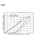
- Fig. 6 is a graph illustrating the relationship between the changes in the drive current value Ia and the pressure Pa of compressed air supplied to the brake booster 12 with a comparative example in which the first signal Sb1 is used to control the proportional control valve 18 and a reference example in which the command signal Sc is used to control the proportional control valve 18. As shown in Fig. 6 , this shows that the hysteresis in the reference example is significantly smaller than that of the comparative example.
- the brake system 10 according to the first embodiment has the following advantages.
- a brake system according to a second embodiment will now be described with reference to Figs. 7 and 8 .
- the brake system according to the second embodiment has the same main configuration as the brake system according to the first embodiment.
- the following detailed description focuses on the parts that differ from the first embodiment, and like or same reference numerals are given to those parts that are the same as the corresponding parts of the first embodiment. Such components will not be described in detail.
- the ECU 31 includes a frequency setting unit 55.
- the frequency setting unit 55 sets the frequency f2 of a pulse signal generated by a second signal generator 57 of the command signal generation unit 32.
- the frequency setting unit 55 calculates the frequency f2 based on the determination value Vj, which is indicated by the determination signal S6 received from the second subtractor 46.
- the frequency setting unit 55 sets the frequency f2 based on, for example, a frequency table 56 stored in the memory 34.
- the frequency table 56 defines a frequency suitable to control the proportional control valve 18 of the pneumatic circuit. This frequency increases as the determination value Vj increases, with the minimum value of 0 Hz (direct current) and the maximum value of 100 Hz.
- the frequency setting unit 55 outputs a frequency signal Sf, which indicates the calculated the frequency f2, to the command signal generation unit 32.
- the second signal generator 57 In the command signal generation unit 32, the second signal generator 57 generates a second signal S11 of the frequency f2, of which the pulse width is determined in advance, based on the frequency signal Sf from the frequency setting unit 55.
- the second signal generator 52 outputs the generated second signal S11 to the multiplier 53.
- the multiplier 53 multiplies the first signal Sb1, which is a high-frequency signal, by the second signal S11, which is a low-frequency signal.
- a section where the first signal Sb1 and the second signal S11 are both set as ON-sections is set as an ON-section, thereby generating the command signal Sc having the supply voltage Vo.
- the command signal generation unit 32 multiplies the first signal Sb1 by the second signal S11 to generate the command signal Sc, in which a power supply region A, where the ON-section is repeated at the frequency f1, is repeated at the frequency f2.
- the frequency of the command signal Sc increases so that the proportion of the power supply region A per unit of time increases.
- the command signal generation unit 32 outputs the generated command signal Sc to the proportional control valve 18.
- Fig. 8A shows examples of various types of signals when the target current value Itrg is small
- Fig. 8B shows the examples of the signals when the target current value Itrg is large.
- the brake system 10 according to the second embodiment has the following advantage (4) in addition to advantage (1) of the first embodiment.
- the first and second embodiments may be modified as described below.
- the controller 30 may be implemented by a single ECU including the functional units of the ECU 31 and the functional units of the command signal generation unit 32.
- the first signal Sb1 may be a high-frequency signal having a predetermined duty cycle.
- the ECU 31 sets the pulse width of the second signal S10 based on the determination value Vj in the first embodiment, where the frequency of the second signal S10 is fixed. Further, the ECU 31 sets the frequency of the second signal S11 based on the determination value Vj in the second embodiment, where the pulse width of the second signal S10 is fixed.
- the duty cycle D1 of the second signal S10 is not limited to 50%.
- the frequency f2 of the second signal S10 simply needs to be less than or equal to 100 Hz and is not limited to 70 Hz.
Landscapes
- Engineering & Computer Science (AREA)
- Transportation (AREA)
- Mechanical Engineering (AREA)
- Physics & Mathematics (AREA)
- Fluid Mechanics (AREA)
- Braking Systems And Boosters (AREA)
- Regulating Braking Force (AREA)
- Magnetically Actuated Valves (AREA)
Abstract
Description
- The present invention relates to a brake system including an electronic control-type proportional control valve arranged on a pneumatic circuit of an air brake.
- An air brake is employed for a brake system of a large automobile such as a truck in order to produce a larger braking force. In an example of an air brake, the compressed air compressed by a compressor driven by the power of the engine is stored in the air tank, and the stored compressed air is supplied to the brake booster, thereby activating the brake.
Patent Document 1 describes a recent example of a brake system including an air brake. When it is determined that the automobile is highly likely to collide with a front obstacle, the brake system functions to support avoidance of the collision by automatically activating the brake. - The example of the brake system having such a function includes a first passage and a second passage that serve as supply passages for compressed air from the air tank to the brake booster. The first passage includes a brake valve that opens when the brake pedal is operated. The second passage includes an electronic control-type proportional control valve of which the open degree varies in a linear manner depending on the level of a drive current. The proportional control valve is controlled by a controller. When the controller determines that the collision is highly likely to occur, the controller causes the proportional control valve to open, thereby supplying compressed air through the second passage to the brake booster. The pressure of the compressed air supplied to the brake booster is increased by increasing the opening degree of the proportional control valve as the distance of the obstacle becomes closer.
- Patent Document 1: Japanese Laid-Open Patent Publication No.
2009-149111 - The proportional control valve has a characteristic in which the pressure of compressed air, which is an output value, differs depending on the directivity of an input value applied to the proportional control valve. This characteristic is referred to as hysteresis. Further, the controller may control the proportional control valve in addition to other devices such as a hydraulic device. In this case, the controller is normally designed to generate a signal having a high frequency of 1 kHz or higher, which is favorable for controlling a hydraulic device, and output the generated high-frequency signal. The high-frequency signal tends to increase the hysteresis of the proportional control valve. Thus, the above-described brake system is required to reduce the hysteresis even if the high-frequency signal is generated as a signal to the proportional control valve.
- It is an objective of the present invention to provide a brake system that reduces hysteresis that occurs in an electronic control-type proportional control valve arranged on a pneumatic circuit even if a high-frequency signal is generated as a signal to the proportional control valve.
- A brake system includes an air tank that stores compressed air, a brake booster configured to activate a brake when supplied with the compressed air, and a pneumatic circuit including a first passage that supplies the compressed air from the air tank to the brake booster. The first passage includes a brake valve of which an opening degree is controlled in accordance with a depression amount of a brake pedal. The pneumatic circuit also includes a second passage that supplies the compressed air from the air tank to the brake booster. The second passage includes a proportional control valve of which an opening degree is controlled through electronic control. The brake system also includes a control unit configured to control the proportional control valve. The control unit includes a first signal generator configured to generate a first signal. The first signal is a pulse signal having a first frequency and indicates a drive amount of the proportional control valve. The control unit also includes a second signal generator configured to generate a second signal. The second signal is a pulse signal having a second frequency, which is less than or equal to one-tenth of the first frequency The control unit further includes a third signal generator configured to generate a command signal for the proportional control valve by multiplying the first signal by the second signal.
-
-
Fig. 1 is a diagram schematically illustrating the structure of a brake system according to a first embodiment. -
Fig. 2 is a block diagram schematically illustrating the configuration of an example of a controller in the brake system shown inFig. 1 . -
Fig. 3 is a functional block diagram illustrating the example of the controller in the brake system shown inFig. 1 . -
Fig. 4 is a diagram schematically illustrating examples of various types of signals generated in the ECU of the controller shown inFig. 1 . -
Fig. 5 is a diagram schematically illustrating examples of various types of signals generated in the controller shown inFig. 1 . -
Fig. 6 is a graph illustrating the relationship between a drive current value and pressure in the brake system shown inFig. 1 by comparing a reference example with a comparative example. -
Fig. 7 is a functional block diagram illustrating an example of a controller of a brake system according to a second embodiment. -
Fig. 8A is a diagram schematically illustrating examples of various types of signals generated in the controller shown inFig. 7 , showing an example in which a target current value is small. -
Fig. 8B is a diagram schematically illustrating the examples of various types of signals generated in the controller shown inFig. 7 , showing an example in which the target current value is large. - A brake system according to a first embodiment will now be described with reference to
Figs. 1 to 6 . - As shown in
Fig. 1 , apneumatic circuit 10A of abrake system 10 includes anair tank 11 that stores compressed air compressed by a compressor driven by the engine. When the compressed air in theair tank 11 is supplied to abrake booster 12, the brake is activated. - The
pneumatic circuit 10A includes afirst passage 13 and asecond passage 14 that serve as supply passages through which compressed air in theair tank 11 is supplied to thebrake booster 12. Thefirst passage 13 includes afirst supply passage 15 connected to theair tank 11 and abrake valve 16 arranged on thefirst supply passage 15. Thebrake valve 16 controls the pressure of compressed air supplied to thebrake booster 12 in accordance with the depression amount of the brake pedal operated by a driver. Thebrake valve 16 supplies compressed air having a higher pressure to thebrake booster 12 as the depression amount of the brake pedal becomes larger. - The
second passage 14 includes asecond supply passage 17 and aproportional control valve 18. Thesecond supply passage 17 is connected to theair tank 11 via a part of thefirst supply passage 15 located upstream of thebrake valve 16. Theproportional control valve 18 is arranged on thesecond supply passage 17. Theproportional control valve 18 is an electronic control-type proportional control valve controlled by acontroller 30. As the opening degree of theproportional control valve 18 increases, the pressure of compressed air supplied to thebrake booster 12 increases. Thecontroller 30 determines whether the possibility of the vehicle colliding with a front obstacle detected by a millimeter wave radar is high or low based on various types of information such as the vehicle speed and the distance to the obstacle detected by the millimeter wave rader. When determining that the possibility of the collision is high, thecontroller 30 opens theproportional control valve 18. Further, thecontroller 30 controls the opening degree of theproportional control valve 18 such that the pressure of compressed air supplied to thebrake booster 12 becomes higher as the distance to the obstacle becomes closer. In thepneumatic circuit 10A, thefirst supply passage 15 and thesecond supply passage 17 may be connected to theair tank 11 independently from each other. - The
pneumatic circuit 10A includes ashuttle valve 19. Theshuttle valve 19 includes an inlet to which thefirst supply passage 15 is connected and another inlet to which thesecond supply passage 17 is connected. Theshuttle valve 19 supplies, to thebrake booster 12 through acommon passage 20, the higher-pressure one of the compressed air supplied from thefirst supply passage 15 and the compressed air supplied from thesecond supply passage 17. - More specifically, in the
first passage 13, the compressed air flows from theair tank 11 into thefirst supply passage 15, passes through thebrake valve 16, and then flows into theshuttle valve 19. In thesecond passage 14, the compressed air flows from theair tank 11 into thesecond supply passage 17, passes through theproportional control valve 18, and then flows into theshuttle valve 19. In both thefirst passage 13 and thesecond passage 14, compressed air flows from theshuttle valve 19 through thecommon passage 20 to thebrake booster 12. - The
brake system 10 includes apressure sensor 26 located in thecommon passage 20, which connects theshuttle valve 19 to thebrake booster 12. Thepressure sensor 26 detects a pressure Pa of compressed air flowing through thecommon passage 20. Thepressure sensor 26 outputs a signal indicating the detected pressure Pa to thecontroller 30. Thebrake system 10 includes acurrent sensor 28 located in a circuit that supplies a power of a supply voltage Vo from thecontroller 30 to theproportional control valve 18. Thecurrent sensor 28 detects a drive current value Ia of theproportional control valve 18. Thecurrent sensor 28 outputs a signal indicating the detected drive current value Ia to thecontroller 30. Thecontroller 30 is powered by apower supply 29 to control theproportional control valve 18. - The
controller 30 that controls theproportional control valve 18 will now be described with reference toFigs. 2 to 6 . - As shown in
Fig. 2 , thecontroller 30 is configured mainly by an electronic control unit (ECU) 31 and includes theECU 31 and a commandsignal generation unit 32. Thecontroller 30 may include a microcomputer and/or a dedicated hardware (application specific integrated circuit; ASIC) that executes at least some of various types of processes. That is, the ECU 50 may be configured by circuitry including 1) one or more processors (microcomputers) running on computer programs (software), 2) one or more dedicated hardware circuits such as ASIC, or 3) a combination thereof. More specifically, theECU 31 includes for example, aprocessor 33, amemory 34, aninput interface 35, and anoutput interface 36 that are connected to one another by abus 37. TheECU 31 obtains signals from thepressure sensor 26 and thecurrent sensor 28 via theinput interface 35. TheECU 31 executes various types of processes based on a program and various types of data stored in thememory 34 as well as the pressure Pa and the drive current value Ia received from thesensors ECU 31 outputs a first signal, which indicates the drive amount of theproportional control valve 18, to the commandsignal generation unit 32 via theoutput interface 36. The commandsignal generation unit 32 generates a command signal Sc based on the first signal and applies the generated command signal Sc to theproportional control valve 18. - As shown in
Fig. 3 , theECU 31 includes, as various types of functional units, atarget pressure calculator 41, a targetcurrent calculator 42, anLPF unit 43, afirst subtractor 44, aPID unit 45, asecond subtractor 46, acarrier wave generator 47, and acomparator 48. - The
target pressure calculator 41 calculates a target pressure Ptrg, which is the pressure of compressed air supplied to thebrake booster 12, based on, for example, the vehicle speed and the distance to an obstacle. Then, thetarget pressure calculator 41 outputs a target pressure signal S1, which indicates the target pressure Ptrg, to the targetcurrent calculator 42. - The target
current calculator 42 calculates a target current value Itrg, which is a target value of the drive current of theproportional control valve 18, based on the target pressure Ptrg and a target current table 49 stored in thememory 34. The target current table 49 defines the target current value Itrg such that the target current value Itrg increases as the target pressure Ptrg increases. The targetcurrent calculator 42 outputs a target current signal S2, which indicates the calculated target current value Itrg. - The LPF (Low Pass Filter)
unit 43 eliminates a high-frequency component included in a signal from thecurrent sensor 28 and outputs a drive current signal S3, which indicates the drive current value Ia of theproportional control valve 18, to thefirst subtractor 44. - The
first subtractor 44 calculates a difference ΔI between the target current value Itrg, which is indicated by the target current signal S2, and the drive current value la, which is indicated by the drive current signal S3. Then, thefirst subtractor 44 outputs a difference signal S4, which indicates the difference ΔI, to thePID unit 45. - The PID (Proportional Integral Differential)
unit 45 calculates a correction value Ic used to correct the target current value Itrg based on the difference ΔI, which is calculated by thefirst subtractor 44. The correction value Ic is the sum of a proportional term used to perform proportional control based on the difference ΔI, an integral term used to perform integral control based on the difference ΔI, and a differential term used to perform differential control based on the difference ΔI. ThePID unit 45 outputs a correction signal S5, which indicates the correction value Ic, to thesecond subtractor 46. - The
second subtractor 46 subtracts the correction value Ic, which is indicated by the correction signal S5, from the target current value Itrg, which is indicated by the target current signal S2. Then, thesecond subtractor 46 calculates a drive current value lat, which is the drive amount of theproportional control valve 18 suitable for achieving the target pressure Ptrg, as a determination value Vj. The determination value Vj is used to generate a first signal Sb1, which serves as a base for generating the command signal Sc. Thesecond subtractor 46 outputs a determination signal S6, which indicates the determination value Vj, to thecomparator 48. Thetarget pressure calculator 41, the targetcurrent calculator 42, theLPF unit 43, thefirst subtractor 44, thePID unit 45, and thesecond subtractor 46 configure a drive amount calculation unit. - The
carrier wave generator 47 generates a carrier wave such as a triangle wave and a sawtooth wave. Thecarrier wave generator 47 of the present embodiment generates a triangle wave to generate the first signal Sb1 and outputs a triangle wave signal S7, which is the generated triangle wave, to thecomparator 48. A triangle wave frequency f1 is set to a frequency of 1 kHz or higher, which is higher than a frequency f2 of a second signal generated by a second signal generator 52 (described later). For example, the frequency f1 is set to 1650 Hz. The frequency f1 corresponds to a first frequency and is used by theECU 31 when generating a command signal to other devices suitable for control at a frequency of 1 kHz or higher, such as a hydraulic device. It is preferred that the frequency f1 be greater than or equal to approximately 1 kHz to control a hydraulic device. - The
comparator 48 functions as a first signal generator. Thecomparator 48 compares the determination value Vj, which is indicated by the determination signal S6, with a value of the triangle wave signal S7 at a corresponding point in time. This generates the first signal Sb1 of the frequency f1, at which a section where the determination signal S6 has a larger value than the triangle wave signal S7 is set as an ON-section. Thus, as the determination value Vj corresponding to the drive current value lat, which is the drive amount of theproportional control valve 18 suitable for achieving the target pressure Ptrg, becomes larger, the pulse width of the first signal Sb1 is set to be larger. The first signal Sb1 is a pulse signal having the supply voltage Vo. - More specifically, as shown in
Fig. 4 , theECU 31 generates the determination signal S6, in which the target current signal S2 is corrected by using the correction signal S5, and compares the determination signal S6 with the triangle wave signal S7 to generate the first signal Sb1 of the frequency f1. Then, theECU 31 outputs the generated first signal Sb1 to the commandsignal generation unit 32. - As shown in
Figs. 3 and5 , the commandsignal generation unit 32 includes thesecond signal generator 52 and amultiplier 53, which functions as a third signal generator. Thesecond signal generator 52 generates a square wave, which is a pulse signal used to generate the command signal Sc based on the first signal Sb1. Then, thesecond signal generator 52 outputs a second signal S10, which indicates the generated square wave, to themultiplier 53. The frequency f2 of the second signal S10 corresponds to a second frequency. It is preferred that the frequency f2 be less than or equal to one-tenth of the first frequency, for example, less than or equal to approximately 100 Hz. In the present embodiment, the second frequency f2 is set to be suitable for controlling the opening degree of theproportional control valve 18. Further, the second frequency f2 is less than or equal to 100 Hz, which is lower than the frequency of a triangle wave generated by thecarrier wave generator 47, for example, 70 Hz. The second signal S10 has a duty cycle D1, which is set to 50%. Themultiplier 53 multiplies the first signal Sb1 of the frequency f1, which is a high-frequency signal, by the second signal S10, which is a low-frequency signal. Thus, a section where the first signal Sb1 and the second signal S10 are both set to ON-sections is defined as an ON-section, thereby generating the command signal Sc having the supply voltage Vo. - More specifically, as shown in
Fig. 5 , the commandsignal generation unit 32 multiplies the first signal Sb1 by the second signal S10 to generate the command signal Sc, in which a power supply region A, where the ON-section of the supply voltage Vo is repeated at the frequency f1, is repeated at the frequency f2. Then, the commandsignal generation unit 32 applies the generated command signal Sc to theproportional control valve 18. - The operation of the
brake system 10 will now be described with reference toFig. 6 . - When the
controller 30 determines that the vehicle is highly likely to collide with a front obstacle detected by a millimeter wave radar based on various types of information such as the vehicle speed and the distance to the obstacle detected by the millimeter wave radar, thecontroller 30 opens theproportional control valve 18. Thecontroller 30 generates the command signal Sc to theproportional control valve 18 by multiplying the first signal Sb1 having the frequency f1 (1650 Hz), which is generated by theECU 31, by the second signal S10 having the frequency f2 (70 Hz), which is generated by thesecond signal generator 52. Thus, theproportional control valve 18 receives the command signal, in which the power supply region A, where the ON-section is set at the frequency f1, is repeated at the frequency f2. -
Fig. 6 is a graph illustrating the relationship between the changes in the drive current value Ia and the pressure Pa of compressed air supplied to thebrake booster 12 with a comparative example in which the first signal Sb1 is used to control theproportional control valve 18 and a reference example in which the command signal Sc is used to control theproportional control valve 18. As shown inFig. 6 , this shows that the hysteresis in the reference example is significantly smaller than that of the comparative example. - The
brake system 10 according to the first embodiment has the following advantages. - (1) The
proportional control valve 18 receives the command signal Sc. In the command signal Sc, the power supply region A, where the ON-section is repeated at the frequency f1 of the first signal Sb1, is repeated at the frequency f2 of the second signal S10. The frequency f1 of the ON-section in the power supply region A is sufficiently higher than the frequency f2 of the second signal S10. Thus, theproportional control valve 18 receives the command signal Sc, which substantially has the frequency f2 of the second signal S10, and is supplied with the supply voltage Vo substantially at the frequency f2. This reduces the frequency of the command signal received by theproportional control valve 18, thereby reducing hysteresis that occurs in theproportional control valve 18. As a result, the control accuracy of the pressure Pa using theproportional control valve 18 is improved. - (2) The
controller 30 includes theECU 31, which generates the first signal Sb1, and the commandsignal generation unit 32, which generates the command signal Sc based on the first signal Sb1. Thus, while theECU 31 is configured to generate various types of signals at the frequency f1 of the first signal Sb1, the commandsignal generation unit 32 modulates the signal Sc received by theproportional control valve 18 to a low-frequency pulse signal of substantially less than or equal to 100 Hz. This allows the command signal Sc to be generated at a frequency suitable for theproportional control valve 18 without changing the basic design of theECU 31. - (3) While setting each of the frequency f2 and the duty cycle D1 of the second signal S10 to be a fixed value, the
controller 30 controls the drive current value Ia of theproportional control valve 18 by controlling the pulse width of the first signal Sb1. In such a configuration, since the frequency f2 of the second signal S10 is fixed, the performance of responding to the variation in the target current value Itrg increases. Further, theproportional control valve 18 can be controlled at a frequency corresponding to the characteristic of theproportional control valve 18. - A brake system according to a second embodiment will now be described with reference to
Figs. 7 and8 . The brake system according to the second embodiment has the same main configuration as the brake system according to the first embodiment. Thus, in the second embodiment, the following detailed description focuses on the parts that differ from the first embodiment, and like or same reference numerals are given to those parts that are the same as the corresponding parts of the first embodiment. Such components will not be described in detail. - As shown in
Fig. 7 , in thecontroller 30, theECU 31 includes afrequency setting unit 55. Thefrequency setting unit 55 sets the frequency f2 of a pulse signal generated by asecond signal generator 57 of the commandsignal generation unit 32. Thefrequency setting unit 55 calculates the frequency f2 based on the determination value Vj, which is indicated by the determination signal S6 received from thesecond subtractor 46. Thefrequency setting unit 55 sets the frequency f2 based on, for example, a frequency table 56 stored in thememory 34. The frequency table 56 defines a frequency suitable to control theproportional control valve 18 of the pneumatic circuit. This frequency increases as the determination value Vj increases, with the minimum value of 0 Hz (direct current) and the maximum value of 100 Hz. Thefrequency setting unit 55 outputs a frequency signal Sf, which indicates the calculated the frequency f2, to the commandsignal generation unit 32. - In the command
signal generation unit 32, thesecond signal generator 57 generates a second signal S11 of the frequency f2, of which the pulse width is determined in advance, based on the frequency signal Sf from thefrequency setting unit 55. Thesecond signal generator 52 outputs the generated second signal S11 to themultiplier 53. - The
multiplier 53 multiplies the first signal Sb1, which is a high-frequency signal, by the second signal S11, which is a low-frequency signal. Thus, a section where the first signal Sb1 and the second signal S11 are both set as ON-sections is set as an ON-section, thereby generating the command signal Sc having the supply voltage Vo. - More specifically, as shown in
Fig. 8A and 8B , the commandsignal generation unit 32 multiplies the first signal Sb1 by the second signal S11 to generate the command signal Sc, in which a power supply region A, where the ON-section is repeated at the frequency f1, is repeated at the frequency f2. When the drive current of theproportional control valve 18 is set to be large, the frequency of the command signal Sc increases so that the proportion of the power supply region A per unit of time increases. The commandsignal generation unit 32 outputs the generated command signal Sc to theproportional control valve 18.Fig. 8A shows examples of various types of signals when the target current value Itrg is small, andFig. 8B shows the examples of the signals when the target current value Itrg is large. The examination of the relationship between the drive current value Ia and the pressure P with the second embodiment employed as a reference example reveals that the hysteresis of the reference example significantly decreases in the second embodiment in the same manner as the relationship between the comparison example and the reference example inFig. 6 . - The
brake system 10 according to the second embodiment has the following advantage (4) in addition to advantage (1) of the first embodiment. - (4) As the drive amount of the
proportional control valve 18 decreases, the frequency f2 of the second signal S11 decreases. Thus, the power consumption is effectively reduced as the drive amount of theproportional control valve 18 decreases. - The first and second embodiments may be modified as described below.
- In the first and second embodiments, the
controller 30 may be implemented by a single ECU including the functional units of theECU 31 and the functional units of the commandsignal generation unit 32. - In the first and second embodiments, the first signal Sb1 may be a high-frequency signal having a predetermined duty cycle. In this case, the
ECU 31 sets the pulse width of the second signal S10 based on the determination value Vj in the first embodiment, where the frequency of the second signal S10 is fixed. Further, theECU 31 sets the frequency of the second signal S11 based on the determination value Vj in the second embodiment, where the pulse width of the second signal S10 is fixed. - In the first embodiment, the duty cycle D1 of the second signal S10 is not limited to 50%.
- In the first embodiment, the frequency f2 of the second signal S10 simply needs to be less than or equal to 100 Hz and is not limited to 70 Hz.
Claims (6)
- A brake system comprising:an air tank that stores compressed air;a brake booster configured to activate a brake when supplied with the compressed air;a pneumatic circuit includinga first passage that supplies the compressed air from the air tank to the brake booster, wherein the first passage includes a brake valve of which an opening degree is controlled in accordance with a depression amount of a brake pedal, anda second passage that supplies the compressed air from the air tank to the brake booster, wherein the second passage includes a proportional control valve of which an opening degree is controlled through electronic control; anda control unit configured to control the proportional control valve,wherein the control unit includesa first signal generator configured to generate a first signal, wherein the first signal is a pulse signal having a first frequency and indicates a drive amount of the proportional control valve,a second signal generator configured to generate a second signal, wherein the second signal is a pulse signal having a second frequency, which is less than or equal to one-tenth of the first frequency, anda third signal generator configured to generate a command signal for the proportional control valve by multiplying the first signal by the second signal.
- The brake system according to claim 1, wherein
the first frequency is greater than or equal to approximately 1 kHz, and
the second frequency is less than or equal to approximately 100 kHz. - The brake system according to claim 1 or 2, wherein
the first signal has a fixed frequency and a pulse width that increases as the drive amount of the proportional control valve increases, and
the second signal has a fixed frequency and a fixed pulse width. - The brake system according to claim 3, wherein the second signal is a square wave of which a duty cycle is set to 50%.
- The brake system according to claim 1 or 2, wherein
the first signal has a fixed frequency and a pulse width that increases as the drive amount of the proportional control valve increases, and
the second signal has a frequency that increases as the drive amount of the proportional control valve increases and a fixed pulse width. - The brake system according to any one of claims 1 to 5, wherein the control unit includes
an electronic control unit including the first signal generator and a drive amount calculation unit that calculates the drive amount of the proportional control valve, and
a command signal generation unit including the second signal generator and the third signal generator.
Applications Claiming Priority (2)
| Application Number | Priority Date | Filing Date | Title |
|---|---|---|---|
| JP2016221877A JP6787757B2 (en) | 2016-11-14 | 2016-11-14 | Brake system |
| PCT/JP2017/039571 WO2018088305A1 (en) | 2016-11-14 | 2017-11-01 | Brake system |
Publications (2)
| Publication Number | Publication Date |
|---|---|
| EP3539833A1 true EP3539833A1 (en) | 2019-09-18 |
| EP3539833A4 EP3539833A4 (en) | 2020-03-25 |
Family
ID=62110390
Family Applications (1)
| Application Number | Title | Priority Date | Filing Date |
|---|---|---|---|
| EP17869974.0A Withdrawn EP3539833A4 (en) | 2016-11-14 | 2017-11-01 | Brake system |
Country Status (4)
| Country | Link |
|---|---|
| US (1) | US20190256066A1 (en) |
| EP (1) | EP3539833A4 (en) |
| JP (1) | JP6787757B2 (en) |
| WO (1) | WO2018088305A1 (en) |
Families Citing this family (3)
| Publication number | Priority date | Publication date | Assignee | Title |
|---|---|---|---|---|
| US11479249B2 (en) * | 2018-10-10 | 2022-10-25 | Waterblasting, Llc | Speed control system for road equipment |
| JP7282538B2 (en) * | 2019-02-08 | 2023-05-29 | ナブテスコオートモーティブ株式会社 | Vehicle, vehicle braking method, air brake system control method, and air brake system control device |
| KR102804695B1 (en) * | 2019-10-23 | 2025-05-08 | 에이치엘만도 주식회사 | Electric brake system and control method thereof |
Family Cites Families (10)
| Publication number | Priority date | Publication date | Assignee | Title |
|---|---|---|---|---|
| US5050940A (en) * | 1990-02-05 | 1991-09-24 | Allied-Signal Inc. | Brake control and anti-skid system |
| JPH0958446A (en) * | 1995-08-28 | 1997-03-04 | Jidosha Kiki Co Ltd | Trailer brake control method and presuming method for coupling force used in the control method |
| JPH11287351A (en) * | 1998-04-01 | 1999-10-19 | Tosok Corp | Proportional solenoid valve driving device |
| JP2000283325A (en) * | 1999-03-30 | 2000-10-13 | Aisin Seiki Co Ltd | Control device for proportional solenoid valve |
| JP4724276B2 (en) * | 2000-08-08 | 2011-07-13 | 株式会社加藤製作所 | Brake control device for work vehicles |
| DE102005058799A1 (en) * | 2005-12-09 | 2007-06-14 | Wabco Gmbh | Electropneumatic brake control device |
| JP2009149111A (en) * | 2007-12-18 | 2009-07-09 | Mitsubishi Fuso Truck & Bus Corp | Vehicular brake device |
| JP5429518B2 (en) * | 2008-09-12 | 2014-02-26 | 株式会社アドヴィックス | Braking control device |
| JP6268012B2 (en) * | 2014-03-19 | 2018-01-24 | 株式会社エー・シー・イー | Control method of proportional solenoid valve |
| CN106080564B (en) * | 2016-08-18 | 2019-02-19 | 陕西同力重工股份有限公司 | The wet brake system of engineering dump truck double-loop air braking |
-
2016
- 2016-11-14 JP JP2016221877A patent/JP6787757B2/en active Active
-
2017
- 2017-11-01 US US16/347,936 patent/US20190256066A1/en not_active Abandoned
- 2017-11-01 WO PCT/JP2017/039571 patent/WO2018088305A1/en not_active Ceased
- 2017-11-01 EP EP17869974.0A patent/EP3539833A4/en not_active Withdrawn
Also Published As
| Publication number | Publication date |
|---|---|
| US20190256066A1 (en) | 2019-08-22 |
| JP6787757B2 (en) | 2020-11-18 |
| WO2018088305A1 (en) | 2018-05-17 |
| JP2018079745A (en) | 2018-05-24 |
| EP3539833A4 (en) | 2020-03-25 |
Similar Documents
| Publication | Publication Date | Title |
|---|---|---|
| US20190256066A1 (en) | Brake system | |
| US10926694B2 (en) | Braking apparatus and method for vehicle | |
| US6142586A (en) | Brake force control apparatus | |
| JP2022045171A (en) | Brake system | |
| JP2022045171A5 (en) | ||
| CN107800332B (en) | The controller for motor of the multiple motors of independent control | |
| US10988128B2 (en) | Method and device for controlling a hydraulic brake system | |
| US20160114772A1 (en) | Methods and systems for boosting trailer brake output | |
| JP2002104173A (en) | Vehicle hydraulic brake system | |
| US20210402970A1 (en) | Method and control device for controlling a parking brake for a vehicle, and parking brake system for a vehicle | |
| JP4089394B2 (en) | Electric power steering device | |
| US9889834B2 (en) | Hydraulic brake assist vacuum maintenance system and method | |
| CN104884317A (en) | Control device for a brake system of a vehicle, and method for operating a brake system of a vehicle | |
| CN111183075B (en) | Brake device for vehicle | |
| CN105172770B (en) | Magnetic valve controller and its control method | |
| CN104648362A (en) | Wheel cylinder hydraulic pressure control method based on mechanical electronic hydraulic brake system | |
| US11572051B2 (en) | Evaluation electronics and method for estimating a master brake cylinder pressure in a vehicle brake system equipped with an electromechanical brake booster | |
| US6366038B1 (en) | Method and circuit for generating a pulse-width modulated actuating signal for a direct current actuator | |
| US12097836B2 (en) | Vehicle brake system and method for operating a vehicle brake system | |
| JP4677964B2 (en) | Electric brake device | |
| US12261559B2 (en) | Motor control device | |
| JP2007091121A (en) | Motor control device and electric power steering device using the same | |
| JP2017206082A (en) | Electric air compressor control device | |
| JP4483322B2 (en) | Booster | |
| KR102620008B1 (en) | Apparatus and method for controlling electric booster brake |
Legal Events
| Date | Code | Title | Description |
|---|---|---|---|
| STAA | Information on the status of an ep patent application or granted ep patent |
Free format text: STATUS: THE INTERNATIONAL PUBLICATION HAS BEEN MADE |
|
| PUAI | Public reference made under article 153(3) epc to a published international application that has entered the european phase |
Free format text: ORIGINAL CODE: 0009012 |
|
| STAA | Information on the status of an ep patent application or granted ep patent |
Free format text: STATUS: REQUEST FOR EXAMINATION WAS MADE |
|
| 17P | Request for examination filed |
Effective date: 20190425 |
|
| AK | Designated contracting states |
Kind code of ref document: A1 Designated state(s): AL AT BE BG CH CY CZ DE DK EE ES FI FR GB GR HR HU IE IS IT LI LT LU LV MC MK MT NL NO PL PT RO RS SE SI SK SM TR |
|
| AX | Request for extension of the european patent |
Extension state: BA ME |
|
| DAV | Request for validation of the european patent (deleted) | ||
| DAX | Request for extension of the european patent (deleted) | ||
| A4 | Supplementary search report drawn up and despatched |
Effective date: 20200225 |
|
| RIC1 | Information provided on ipc code assigned before grant |
Ipc: B60T 13/36 20060101ALI20200219BHEP Ipc: F16K 31/06 20060101ALI20200219BHEP Ipc: B60T 8/17 20060101AFI20200219BHEP |
|
| GRAP | Despatch of communication of intention to grant a patent |
Free format text: ORIGINAL CODE: EPIDOSNIGR1 |
|
| STAA | Information on the status of an ep patent application or granted ep patent |
Free format text: STATUS: GRANT OF PATENT IS INTENDED |
|
| INTG | Intention to grant announced |
Effective date: 20200924 |
|
| STAA | Information on the status of an ep patent application or granted ep patent |
Free format text: STATUS: THE APPLICATION IS DEEMED TO BE WITHDRAWN |
|
| 18D | Application deemed to be withdrawn |
Effective date: 20210205 |