EP3539811B1 - Vehicle having a tank holding device - Google Patents
Vehicle having a tank holding device Download PDFInfo
- Publication number
- EP3539811B1 EP3539811B1 EP18182869.0A EP18182869A EP3539811B1 EP 3539811 B1 EP3539811 B1 EP 3539811B1 EP 18182869 A EP18182869 A EP 18182869A EP 3539811 B1 EP3539811 B1 EP 3539811B1
- Authority
- EP
- European Patent Office
- Prior art keywords
- tank
- members
- vehicle
- mounting frame
- frame
- Prior art date
- Legal status (The legal status is an assumption and is not a legal conclusion. Google has not performed a legal analysis and makes no representation as to the accuracy of the status listed.)
- Active
Links
Images


Classifications
-
- B—PERFORMING OPERATIONS; TRANSPORTING
- B60—VEHICLES IN GENERAL
- B60K—ARRANGEMENT OR MOUNTING OF PROPULSION UNITS OR OF TRANSMISSIONS IN VEHICLES; ARRANGEMENT OR MOUNTING OF PLURAL DIVERSE PRIME-MOVERS IN VEHICLES; AUXILIARY DRIVES FOR VEHICLES; INSTRUMENTATION OR DASHBOARDS FOR VEHICLES; ARRANGEMENTS IN CONNECTION WITH COOLING, AIR INTAKE, GAS EXHAUST OR FUEL SUPPLY OF PROPULSION UNITS IN VEHICLES
- B60K15/00—Arrangement in connection with fuel supply of combustion engines or other fuel consuming energy converters, e.g. fuel cells; Mounting or construction of fuel tanks
- B60K15/03—Fuel tanks
- B60K15/063—Arrangement of tanks
- B60K15/067—Mounting of tanks
-
- B—PERFORMING OPERATIONS; TRANSPORTING
- B60—VEHICLES IN GENERAL
- B60K—ARRANGEMENT OR MOUNTING OF PROPULSION UNITS OR OF TRANSMISSIONS IN VEHICLES; ARRANGEMENT OR MOUNTING OF PLURAL DIVERSE PRIME-MOVERS IN VEHICLES; AUXILIARY DRIVES FOR VEHICLES; INSTRUMENTATION OR DASHBOARDS FOR VEHICLES; ARRANGEMENTS IN CONNECTION WITH COOLING, AIR INTAKE, GAS EXHAUST OR FUEL SUPPLY OF PROPULSION UNITS IN VEHICLES
- B60K15/00—Arrangement in connection with fuel supply of combustion engines or other fuel consuming energy converters, e.g. fuel cells; Mounting or construction of fuel tanks
- B60K15/03—Fuel tanks
-
- B—PERFORMING OPERATIONS; TRANSPORTING
- B60—VEHICLES IN GENERAL
- B60K—ARRANGEMENT OR MOUNTING OF PROPULSION UNITS OR OF TRANSMISSIONS IN VEHICLES; ARRANGEMENT OR MOUNTING OF PLURAL DIVERSE PRIME-MOVERS IN VEHICLES; AUXILIARY DRIVES FOR VEHICLES; INSTRUMENTATION OR DASHBOARDS FOR VEHICLES; ARRANGEMENTS IN CONNECTION WITH COOLING, AIR INTAKE, GAS EXHAUST OR FUEL SUPPLY OF PROPULSION UNITS IN VEHICLES
- B60K15/00—Arrangement in connection with fuel supply of combustion engines or other fuel consuming energy converters, e.g. fuel cells; Mounting or construction of fuel tanks
- B60K15/03—Fuel tanks
- B60K15/063—Arrangement of tanks
-
- B—PERFORMING OPERATIONS; TRANSPORTING
- B60—VEHICLES IN GENERAL
- B60K—ARRANGEMENT OR MOUNTING OF PROPULSION UNITS OR OF TRANSMISSIONS IN VEHICLES; ARRANGEMENT OR MOUNTING OF PLURAL DIVERSE PRIME-MOVERS IN VEHICLES; AUXILIARY DRIVES FOR VEHICLES; INSTRUMENTATION OR DASHBOARDS FOR VEHICLES; ARRANGEMENTS IN CONNECTION WITH COOLING, AIR INTAKE, GAS EXHAUST OR FUEL SUPPLY OF PROPULSION UNITS IN VEHICLES
- B60K15/00—Arrangement in connection with fuel supply of combustion engines or other fuel consuming energy converters, e.g. fuel cells; Mounting or construction of fuel tanks
- B60K15/03—Fuel tanks
- B60K2015/03328—Arrangements or special measures related to fuel tanks or fuel handling
- B60K2015/03375—Arrangements or special measures related to fuel tanks or fuel handling to improve security
-
- B—PERFORMING OPERATIONS; TRANSPORTING
- B60—VEHICLES IN GENERAL
- B60K—ARRANGEMENT OR MOUNTING OF PROPULSION UNITS OR OF TRANSMISSIONS IN VEHICLES; ARRANGEMENT OR MOUNTING OF PLURAL DIVERSE PRIME-MOVERS IN VEHICLES; AUXILIARY DRIVES FOR VEHICLES; INSTRUMENTATION OR DASHBOARDS FOR VEHICLES; ARRANGEMENTS IN CONNECTION WITH COOLING, AIR INTAKE, GAS EXHAUST OR FUEL SUPPLY OF PROPULSION UNITS IN VEHICLES
- B60K15/00—Arrangement in connection with fuel supply of combustion engines or other fuel consuming energy converters, e.g. fuel cells; Mounting or construction of fuel tanks
- B60K15/03—Fuel tanks
- B60K2015/03328—Arrangements or special measures related to fuel tanks or fuel handling
- B60K2015/03453—Arrangements or special measures related to fuel tanks or fuel handling for fixing or mounting parts of the fuel tank together
Definitions
- the disclosure relates to a vehicle, and more particularly to a tank holding device in a vehicle.
- a utility vehicle is a slow, but multipurpose vehicle that is commonly driven to transport passengers or goods in a simple environment, such as a golf course or a factory. Most of the utility vehicles utilize traditional gasoline-powered system, where the gasoline is transferred from an external tank.
- US 9,499,045 B2 discloses a working vehicle comprising: a fuel tank; a tank support member conf igured to receive and support the fuel tank from below; and an inverse U-shaped hood support member provided upright in a state of spanning left and right of the fuel tank, the hood support member including an elastic member that acts on an upper portion side of the fuel tank so as to hold the fuel tank at a predetermined position on the tank support member.
- JP 2004 203200 A discloses a fuel-tank support structure which can suppress effectively that the flow sound made when the fuel in a fuel tank flows is transmitted from a vehicle-body floor into a compartment.
- a vehicle frame 1 of a conventional utility vehicle includes a mounting frame 11, a holding frame 12 that is attached to the mounting frame 11, a tank 13 that is disposed between the mounting frame 11 and the holding frame 12, and a pair of screws 14 that secure the tank 13 directly onto the mounting frame 11 through their respective through holes. While the mounting frame 11 and the holding frame 12 confine the tank 13 therebetween, the holding frame 12 serves no role in holding the tank 13 in place. In other words, without a buffer system, stress exerted by the tank 13 due to external lateral movement (e.g. sudden bump in driving) is all concentrated toward the screws 14, which can easily damage the screws 14 and the through holes, or even damage the tank 13. In addition, the tank 13 may be made with different configurations, which may come with misaligned through holes incapable to fit the screws 14 therethrough for securing the tank 13 onto the mounting frame 11.
- an object of the disclosure is to provide a vehicle having a tank holding device that can alleviate at least one of the drawbacks of the prior art.
- an embodiment of the vehicle 2 includes a vehicle frame 3, a tank 4 disposed on the vehicle frame 3, and a tank holding device 5 disposed on the vehicle frame 3 for securing the tank 4 thereon.
- the tank 4 is disposed on either left or right side of the vehicle frame 3, but it may be disposed elsewhere in other embodiments.
- the vehicle frame 3 includes a mounting frame 31 and a holding frame 32 disposed on the mounting frame 31.
- the holding frame 32 has a plurality of spaced-apart support segments 321 connected fixedly to the mounting frame 31, and a connecting segment 322 interconnecting the support segments 321.
- Each of the support segments 321 has a lower support part 323 that is secured to a lower portion of the mounting frame 31, an inclined part 324 that extends obliquely from the lower support part 323 and that is connected to the connecting segment 322, and an upper support part 325 that extends substantially horizontally from the inclined part 324, and that is secured to an upper portion of the mounting frame 31.
- the upper support part 325 of each of the support segments 321 is formed with a threaded hole 326.
- the threaded hole 326 extends substantially vertically in the upper support part 325, but it may extend diagonally in other embodiments.
- the tank 4 is disposed between the mounting frame 31 and the holding frame 32, and is formed with a plurality of horizontally spaced-apart retaining grooves 41 retaining respectively the inclined parts 324 of the support segments 321. While the above configuration allows the support segments 321 to confine the tank 4 from horizontal movement, the upper support parts 325 of the support segments 321 are actually disposed above the tank 4 and does not fit into the retaining groove 41 directly.
- the tank holding device 5 includes a positioning unit 51 that is connected to the holding frame 32 of the vehicle frame 3, and a shock absorbing unit 52 disposed between the mounting frame 31 and the tank 4.
- the shock absorbing unit 52 is made of soft material, such as rubber or foam, for absorbing shock impulses from the vehicle frame 3 to the tank 4.
- the positioning unit 51 is adapted to extent threadedly through the holding frame 32, and has two cushion members 511, two coupling members 512, two threaded members 513 and two nuts 514.
- Each of the cushion members 511 is disposed between the tank 4 and the upper support part 325 of a respective one of the support segments 321 of the holding frame 32, and is retained by a respective one of the retaining grooves 41.
- the coupling members 512 abut respectively against the cushion members 511 and are disposed between the cushion members 511 and the holding frame 32.
- Each of the threaded members 513 extends threadedly through the threaded hole 326 of the upper support part 325 of a respective one of the support segments 321 to be connected to the holding frame 32.
- the nuts 514 are disposed on the holding frame 32, and are connected threadedly and respectively to the threaded members 513.
- each of the cushion members 511 has a main portion 515 that is made of rubber, and an abutment portion 516 that is embedded in a top end of the main portion 515 and that defines a receiving space receiving a respective one of the coupling members 512.
- the abutment portion 516 is made from a hard material such as iron and is made with the main portion 515 as one piece.
- Each of the coupling members 512 is disposed between a respective one of the cushion members 511 and the upper support part 325 of a respective one of the support segments 321, and has an end formed with a threaded engaging hole 517 (see FIG. 3 ) that is engaged threadedly with a respective one of the threaded members 513, and an opposite end abutting against the abutment portion 516 of a respective one of the cushion members 511.
- the abutment portions 516 disperse external force from the coupling members 512 equally throughout the main portions 515 to extend the service life of the main portions 515.
- Each of the threaded members 513 has two opposite ends, each of which is on opposite sides of the upper support part 325 of a respective one of the support segments 321.
- each of the threaded members 513 engages threadedly with the threaded engaging hole 517 of a respective one of the coupling members 512.
- Each of the nuts 514 is disposed on the top side of the upper support part 325 of a respective one of the support segments 321, and each of the coupling members 512 is disposed on the bottom side of the upper support part 325 of a respective one of the support segments 321.
- each of the threaded members 513 When either of the threaded members 513 is adjusted, it is threadedly moved upward or downward to pull or push a respective one of the coupling members 512, which in terms releases or exerts force toward a respective one of the cushion members 511 against the tank 4.
- the threaded member 513 is adapted for pushing a respective one of the cushion members 511 tightly against the tank 4 to secure the tank 4 from any movement.
- each of the threaded members 513 may be further secured by threadedly engaging the respective nuts 514 thereto against the respective upper support parts 325. Due to bigger contact area between the cushion members 511 and the tank 4, exerted force between the two elements is better dispersed throughout to prevent damage to the structure of the tank 4 or the tank holding device 5.
- the abovementioned adjusting configuration of the threaded members 513 may accommodate uses of tanks of different dimensions to improve the compatibility of the tank holding device 5.
- outer surface area of the coupling member 512 is greater than surface area of the threaded member 513 in direct contact with the coupling member 512, such that axial force exerted from the threaded member 513 to the cushion member 511 may be equally dispersed over a larger surface area, creating an overall smaller pressure suitable for extending service life of the cushion member 511.
Landscapes
- Engineering & Computer Science (AREA)
- Life Sciences & Earth Sciences (AREA)
- Sustainable Development (AREA)
- Sustainable Energy (AREA)
- Chemical & Material Sciences (AREA)
- Combustion & Propulsion (AREA)
- Transportation (AREA)
- Mechanical Engineering (AREA)
- Cooling, Air Intake And Gas Exhaust, And Fuel Tank Arrangements In Propulsion Units (AREA)
- Details Of Rigid Or Semi-Rigid Containers (AREA)
Description
- The disclosure relates to a vehicle, and more particularly to a tank holding device in a vehicle.
- A utility vehicle is a slow, but multipurpose vehicle that is commonly driven to transport passengers or goods in a simple environment, such as a golf course or a factory. Most of the utility vehicles utilize traditional gasoline-powered system, where the gasoline is transferred from an external tank.
-
US 9,499,045 B2 -
JP 2004 203200 A - Referring to
FIG. 1 , avehicle frame 1 of a conventional utility vehicle includes amounting frame 11, aholding frame 12 that is attached to themounting frame 11, atank 13 that is disposed between themounting frame 11 and theholding frame 12, and a pair ofscrews 14 that secure thetank 13 directly onto themounting frame 11 through their respective through holes. While themounting frame 11 and theholding frame 12 confine thetank 13 therebetween, theholding frame 12 serves no role in holding thetank 13 in place. In other words, without a buffer system, stress exerted by thetank 13 due to external lateral movement (e.g. sudden bump in driving) is all concentrated toward thescrews 14, which can easily damage thescrews 14 and the through holes, or even damage thetank 13. In addition, thetank 13 may be made with different configurations, which may come with misaligned through holes incapable to fit thescrews 14 therethrough for securing thetank 13 onto themounting frame 11. - Therefore, an object of the disclosure is to provide a vehicle having a tank holding device that can alleviate at least one of the drawbacks of the prior art.
- Other features and advantages of the disclosure will become apparent in the following detailed description of the embodiments with reference to the accompanying drawings, of which:
-
FIG. 1 is a fragmentary perspective view of a conventional tank holding device in a vehicle frame; -
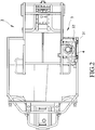
FIG. 2 is a top view of an embodiment of a vehicle according to the disclosure; -
FIG. 3 is a partly fragmentary, exploded perspective view of a tank holding device of the embodiment; -
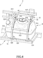
FIG. 4 is a partly fragmentary, assembled perspective view of the embodiment; -
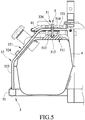
FIG. 5 is a fragmentary sectional view of the embodiment; and -
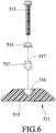
FIG. 6 is a partly exploded sectional view of a cushion member, a coupling member, a nut and a threaded member of the embodiment. - Referring to
FIGS. 2 to 4 , an embodiment of thevehicle 2 according to the disclosure includes avehicle frame 3, atank 4 disposed on thevehicle frame 3, and atank holding device 5 disposed on thevehicle frame 3 for securing thetank 4 thereon. In this embodiment, thetank 4 is disposed on either left or right side of thevehicle frame 3, but it may be disposed elsewhere in other embodiments. - Referring to
FIGS. 3 to 5 , thevehicle frame 3 includes amounting frame 31 and aholding frame 32 disposed on themounting frame 31. Theholding frame 32 has a plurality of spaced-apartsupport segments 321 connected fixedly to themounting frame 31, and a connectingsegment 322 interconnecting thesupport segments 321. Each of thesupport segments 321 has alower support part 323 that is secured to a lower portion of themounting frame 31, aninclined part 324 that extends obliquely from thelower support part 323 and that is connected to theconnecting segment 322, and anupper support part 325 that extends substantially horizontally from theinclined part 324, and that is secured to an upper portion of themounting frame 31. Theupper support part 325 of each of thesupport segments 321 is formed with a threadedhole 326. In this embodiment, the threadedhole 326 extends substantially vertically in theupper support part 325, but it may extend diagonally in other embodiments. Thetank 4 is disposed between themounting frame 31 and theholding frame 32, and is formed with a plurality of horizontally spaced-apart retaininggrooves 41 retaining respectively theinclined parts 324 of thesupport segments 321. While the above configuration allows thesupport segments 321 to confine thetank 4 from horizontal movement, theupper support parts 325 of thesupport segments 321 are actually disposed above thetank 4 and does not fit into theretaining groove 41 directly. - The
tank holding device 5 includes apositioning unit 51 that is connected to theholding frame 32 of thevehicle frame 3, and ashock absorbing unit 52 disposed between themounting frame 31 and thetank 4. Theshock absorbing unit 52 is made of soft material, such as rubber or foam, for absorbing shock impulses from thevehicle frame 3 to thetank 4. In the embodiment, thepositioning unit 51 is adapted to extent threadedly through theholding frame 32, and has twocushion members 511, twocoupling members 512, two threadedmembers 513 and twonuts 514. Each of thecushion members 511 is disposed between thetank 4 and theupper support part 325 of a respective one of thesupport segments 321 of theholding frame 32, and is retained by a respective one of theretaining grooves 41. Thecoupling members 512 abut respectively against thecushion members 511 and are disposed between thecushion members 511 and theholding frame 32. Each of the threadedmembers 513 extends threadedly through the threadedhole 326 of theupper support part 325 of a respective one of thesupport segments 321 to be connected to theholding frame 32. Thenuts 514 are disposed on theholding frame 32, and are connected threadedly and respectively to the threadedmembers 513. - The configuration of each of the
cushion members 511 being retained by a respective one of theretaining grooves 41 prevents therespective cushion members 511 from sliding. As shown inFIG. 6 , each of thecushion members 511 has amain portion 515 that is made of rubber, and anabutment portion 516 that is embedded in a top end of themain portion 515 and that defines a receiving space receiving a respective one of thecoupling members 512. Theabutment portion 516 is made from a hard material such as iron and is made with themain portion 515 as one piece. Each of thecoupling members 512 is disposed between a respective one of thecushion members 511 and theupper support part 325 of a respective one of thesupport segments 321, and has an end formed with a threaded engaging hole 517 (seeFIG. 3 ) that is engaged threadedly with a respective one of the threadedmembers 513, and an opposite end abutting against theabutment portion 516 of a respective one of thecushion members 511. Theabutment portions 516 disperse external force from thecoupling members 512 equally throughout themain portions 515 to extend the service life of themain portions 515. Each of the threadedmembers 513 has two opposite ends, each of which is on opposite sides of theupper support part 325 of a respective one of thesupport segments 321. The lower end of each of the threadedmembers 513 engages threadedly with the threadedengaging hole 517 of a respective one of thecoupling members 512. Each of thenuts 514 is disposed on the top side of theupper support part 325 of a respective one of thesupport segments 321, and each of thecoupling members 512 is disposed on the bottom side of theupper support part 325 of a respective one of thesupport segments 321. - When either of the threaded
members 513 is adjusted, it is threadedly moved upward or downward to pull or push a respective one of thecoupling members 512, which in terms releases or exerts force toward a respective one of thecushion members 511 against thetank 4. As such, the threadedmember 513 is adapted for pushing a respective one of thecushion members 511 tightly against thetank 4 to secure thetank 4 from any movement. After the adjustment, each of the threadedmembers 513 may be further secured by threadedly engaging therespective nuts 514 thereto against the respectiveupper support parts 325. Due to bigger contact area between thecushion members 511 and thetank 4, exerted force between the two elements is better dispersed throughout to prevent damage to the structure of thetank 4 or thetank holding device 5. The abovementioned adjusting configuration of the threadedmembers 513 may accommodate uses of tanks of different dimensions to improve the compatibility of thetank holding device 5. For each of thepositioning units 51, outer surface area of thecoupling member 512 is greater than surface area of the threadedmember 513 in direct contact with thecoupling member 512, such that axial force exerted from the threadedmember 513 to thecushion member 511 may be equally dispersed over a larger surface area, creating an overall smaller pressure suitable for extending service life of thecushion member 511. - In the description above, for the purposes of explanation, numerous specific details have been set forth in order to provide a thorough understanding of the embodiments. It will be apparent, however, to one skilled in the art, that various modifications are possible within the scope of the invention as defined by the appended claims.
Claims (6)
- A vehicle (2) including:a vehicle frame (3) including a mounting frame (31), and a holding frame (32) that is disposed on said mounting frame (31);a tank (4) disposed between said mounting frame (31) and said holding frame (32); anda tank holding device (5) including a positioning unit (51) that is connected to the holding frame (32), and that is for pushing the tank (4) tightly against the mounting frame (31) so as to secure the tank (4) on the mounting frame (31), said positioning unit (51) includes:a plurality of cushion members (511) disposed between the holding frame (32) and the tank (4);a plurality of threaded members (513) connected to the holding frame (32), each of said threaded members (513) being connected threadedly to one of the holding frame (32) and a respective one of said cushion member (511), and being used for pushing the respective one of said cushion members (511) tightly against the tank (4);characterized in that the positioning unit (51) further includes:a plurality of nuts (514) disposed on the holding frame (32), and connected threadedly and respectively to said threaded members (513); anda plurality of coupling members (512) connected respectively to said threaded members (513) and abutting respectively against said cushion members (511), each of said coupling members (512) having an end formed with a threaded engaging hole (517) that is engaged threadedly with a respective one of said threaded members (513), and an opposite end abutting against a respective one of said cushion members (511);wherein each of said cushion members (511) has:a main portion (515) that is made of rubber; andan abutment portion (516) that is made of iron, that is embedded in a top end of said main portion (515), and that defines a receiving space receiving a respective one of said coupling members (512).
- The vehicle (2) as claimed in claim 1, further characterized in that said positioning unit (51) extends threadedly through the holding frame (32).
- The vehicle (2) as claimed in any one of claims 1 and 2, further characterized by a shock absorbing unit (52) disposed between the mounting frame (31) and the tank (4).
- The vehicle (2) as claimed in any one of claims 1 to 34, further characterized in that said tank (4) is formed with a plurality of retaining grooves (41) retaining respectively said cushion members (511) .
- The vehicle (2) as claimed in claim 4, further characterized in that said holding frame (32) has:a plurality of spaced-apart support segments (321) connected fixedly to said mounting frame (31), each of said support segments (321) havinga lower support part (323) that is secured to a lower portion of said mounting frame (31),an inclined part (324) that extends obliquely from said lower support part (323) and that is retained in the respective one of said retaining grooves (41), andan upper support part (325) that extends substantially horizontally from said inclined part (324), and that is secured to an upper portion of said mounting frame (31); anda connecting segment (322) interconnecting said support segments (321).
- The vehicle (2) as claimed in claim 5, further characterized in that:each of said support segments (321) of said holding frame (32) is formed with a threaded hole (326); andeach of said threaded members (513) of said positioning unit (51) extends threadedly through said threaded hole (326) of a respective one of said support segments (321).
Applications Claiming Priority (1)
| Application Number | Priority Date | Filing Date | Title |
|---|---|---|---|
| US15/923,600 US20190283573A1 (en) | 2018-03-16 | 2018-03-16 | Tank holding device and a vehicle having the same |
Publications (2)
| Publication Number | Publication Date |
|---|---|
| EP3539811A1 EP3539811A1 (en) | 2019-09-18 |
| EP3539811B1 true EP3539811B1 (en) | 2021-04-21 |
Family
ID=62947949
Family Applications (1)
| Application Number | Title | Priority Date | Filing Date |
|---|---|---|---|
| EP18182869.0A Active EP3539811B1 (en) | 2018-03-16 | 2018-07-11 | Vehicle having a tank holding device |
Country Status (3)
| Country | Link |
|---|---|
| US (2) | US20190283573A1 (en) |
| EP (1) | EP3539811B1 (en) |
| TW (1) | TWM565140U (en) |
Families Citing this family (4)
| Publication number | Priority date | Publication date | Assignee | Title |
|---|---|---|---|---|
| US11597271B2 (en) * | 2021-01-15 | 2023-03-07 | Ford Global Technologies, Llc | Fuel tank mounting assembly |
| DE102021200626A1 (en) * | 2021-01-25 | 2022-07-28 | Psa Automobiles Sa | Motor vehicle and fuel tank assembly therefor |
| JP7413573B2 (en) * | 2021-01-27 | 2024-01-15 | 株式会社クボタ | Fuel refueling guide and work equipment |
| CN116279720A (en) * | 2023-01-17 | 2023-06-23 | 北京航天益森风洞工程技术有限公司 | Cylindrical tank transfer vehicle |
Family Cites Families (5)
| Publication number | Priority date | Publication date | Assignee | Title |
|---|---|---|---|---|
| US4632356A (en) * | 1984-04-19 | 1986-12-30 | Erich Munz | Vertically adjustable shock-absorbing mounting device |
| JP2004203200A (en) * | 2002-12-25 | 2004-07-22 | Toyota Motor Corp | Fuel tank support structure |
| JP4625351B2 (en) * | 2005-03-25 | 2011-02-02 | 本田技研工業株式会社 | Fuel tank fixing structure |
| JP2014148227A (en) * | 2013-01-31 | 2014-08-21 | Yachiyo Industry Co Ltd | Fitting structure of fuel tank to vehicle body |
| KR101641421B1 (en) * | 2014-01-31 | 2016-07-20 | 가부시끼 가이샤 구보다 | Work vehicle |
-
2018
- 2018-03-16 US US15/923,600 patent/US20190283573A1/en not_active Abandoned
- 2018-05-08 TW TW107205946U patent/TWM565140U/en unknown
- 2018-07-11 EP EP18182869.0A patent/EP3539811B1/en active Active
-
2020
- 2020-12-18 US US17/127,054 patent/US20210101474A1/en not_active Abandoned
Non-Patent Citations (1)
| Title |
|---|
| None * |
Also Published As
| Publication number | Publication date |
|---|---|
| US20210101474A1 (en) | 2021-04-08 |
| EP3539811A1 (en) | 2019-09-18 |
| TWM565140U (en) | 2018-08-11 |
| US20190283573A1 (en) | 2019-09-19 |
Similar Documents
| Publication | Publication Date | Title |
|---|---|---|
| EP3539811B1 (en) | Vehicle having a tank holding device | |
| CN101918648B (en) | Cabin mounting structure for construction machinery | |
| US9518628B2 (en) | Tubular vibration-damping device | |
| US8016067B2 (en) | Vibration isolation assembly | |
| CN100394063C (en) | engine mount | |
| JP2012056563A (en) | Roll rod structure of vehicle | |
| US10661648B2 (en) | Rubber stopper | |
| CN107351940B (en) | Automatic guided transport vehicle chassis and automatic guided transport vehicle | |
| US5605200A (en) | Self attaching upper radiator mount | |
| US6830492B1 (en) | Marine drive trim cylinder with two stage damping system | |
| EP3441639B1 (en) | Damper assembly and damper therefor | |
| KR101337963B1 (en) | Bush for subframe of vehicle | |
| CN104709062A (en) | Tractor vibration damper | |
| CN101432164B (en) | Materials handling vehicles having seats with pivoting backrests | |
| KR101636212B1 (en) | mounting frame structure for automobile | |
| JP7104477B2 (en) | Dynamic damper for automobiles | |
| JP2013224119A (en) | Installation tool of shock absorber | |
| JP5569974B2 (en) | Rubber stopper | |
| US20080169163A1 (en) | Harmonic dampener | |
| CN221340417U (en) | Shock absorber pedal and vehicle | |
| KR20170030963A (en) | Vehicle for leaf spring | |
| KR20160050641A (en) | structure for reducing friction of leaf spring for vehicle | |
| JP7688548B2 (en) | Transmission lift-up mechanism | |
| KR101896706B1 (en) | Device for protecting floating bar of cab bridge parts for truck | |
| CN210423685U (en) | Shifting fork structure |
Legal Events
| Date | Code | Title | Description |
|---|---|---|---|
| PUAI | Public reference made under article 153(3) epc to a published international application that has entered the european phase |
Free format text: ORIGINAL CODE: 0009012 |
|
| STAA | Information on the status of an ep patent application or granted ep patent |
Free format text: STATUS: THE APPLICATION HAS BEEN PUBLISHED |
|
| AK | Designated contracting states |
Kind code of ref document: A1 Designated state(s): AL AT BE BG CH CY CZ DE DK EE ES FI FR GB GR HR HU IE IS IT LI LT LU LV MC MK MT NL NO PL PT RO RS SE SI SK SM TR |
|
| AX | Request for extension of the european patent |
Extension state: BA ME |
|
| STAA | Information on the status of an ep patent application or granted ep patent |
Free format text: STATUS: REQUEST FOR EXAMINATION WAS MADE |
|
| 17P | Request for examination filed |
Effective date: 20200318 |
|
| RBV | Designated contracting states (corrected) |
Designated state(s): AL AT BE BG CH CY CZ DE DK EE ES FI FR GB GR HR HU IE IS IT LI LT LU LV MC MK MT NL NO PL PT RO RS SE SI SK SM TR |
|
| STAA | Information on the status of an ep patent application or granted ep patent |
Free format text: STATUS: EXAMINATION IS IN PROGRESS |
|
| 17Q | First examination report despatched |
Effective date: 20200818 |
|
| GRAP | Despatch of communication of intention to grant a patent |
Free format text: ORIGINAL CODE: EPIDOSNIGR1 |
|
| STAA | Information on the status of an ep patent application or granted ep patent |
Free format text: STATUS: GRANT OF PATENT IS INTENDED |
|
| INTG | Intention to grant announced |
Effective date: 20201125 |
|
| RIN1 | Information on inventor provided before grant (corrected) |
Inventor name: TERUAKI, YAMAMOTO Inventor name: CHUANG-HSIUNG, LIN |
|
| GRAS | Grant fee paid |
Free format text: ORIGINAL CODE: EPIDOSNIGR3 |
|
| GRAA | (expected) grant |
Free format text: ORIGINAL CODE: 0009210 |
|
| STAA | Information on the status of an ep patent application or granted ep patent |
Free format text: STATUS: THE PATENT HAS BEEN GRANTED |
|
| AK | Designated contracting states |
Kind code of ref document: B1 Designated state(s): AL AT BE BG CH CY CZ DE DK EE ES FI FR GB GR HR HU IE IS IT LI LT LU LV MC MK MT NL NO PL PT RO RS SE SI SK SM TR |
|
| REG | Reference to a national code |
Ref country code: GB Ref legal event code: FG4D |
|
| REG | Reference to a national code |
Ref country code: CH Ref legal event code: EP |
|
| REG | Reference to a national code |
Ref country code: DE Ref legal event code: R096 Ref document number: 602018015741 Country of ref document: DE Ref country code: IE Ref legal event code: FG4D |
|
| REG | Reference to a national code |
Ref country code: AT Ref legal event code: REF Ref document number: 1384283 Country of ref document: AT Kind code of ref document: T Effective date: 20210515 |
|
| REG | Reference to a national code |
Ref country code: LT Ref legal event code: MG9D |
|
| REG | Reference to a national code |
Ref country code: AT Ref legal event code: MK05 Ref document number: 1384283 Country of ref document: AT Kind code of ref document: T Effective date: 20210421 |
|
| REG | Reference to a national code |
Ref country code: NL Ref legal event code: MP Effective date: 20210421 |
|
| PG25 | Lapsed in a contracting state [announced via postgrant information from national office to epo] |
Ref country code: AT Free format text: LAPSE BECAUSE OF FAILURE TO SUBMIT A TRANSLATION OF THE DESCRIPTION OR TO PAY THE FEE WITHIN THE PRESCRIBED TIME-LIMIT Effective date: 20210421 Ref country code: BG Free format text: LAPSE BECAUSE OF FAILURE TO SUBMIT A TRANSLATION OF THE DESCRIPTION OR TO PAY THE FEE WITHIN THE PRESCRIBED TIME-LIMIT Effective date: 20210721 Ref country code: NL Free format text: LAPSE BECAUSE OF FAILURE TO SUBMIT A TRANSLATION OF THE DESCRIPTION OR TO PAY THE FEE WITHIN THE PRESCRIBED TIME-LIMIT Effective date: 20210421 Ref country code: LT Free format text: LAPSE BECAUSE OF FAILURE TO SUBMIT A TRANSLATION OF THE DESCRIPTION OR TO PAY THE FEE WITHIN THE PRESCRIBED TIME-LIMIT Effective date: 20210421 Ref country code: HR Free format text: LAPSE BECAUSE OF FAILURE TO SUBMIT A TRANSLATION OF THE DESCRIPTION OR TO PAY THE FEE WITHIN THE PRESCRIBED TIME-LIMIT Effective date: 20210421 Ref country code: FI Free format text: LAPSE BECAUSE OF FAILURE TO SUBMIT A TRANSLATION OF THE DESCRIPTION OR TO PAY THE FEE WITHIN THE PRESCRIBED TIME-LIMIT Effective date: 20210421 |
|
| PG25 | Lapsed in a contracting state [announced via postgrant information from national office to epo] |
Ref country code: IS Free format text: LAPSE BECAUSE OF FAILURE TO SUBMIT A TRANSLATION OF THE DESCRIPTION OR TO PAY THE FEE WITHIN THE PRESCRIBED TIME-LIMIT Effective date: 20210821 Ref country code: GR Free format text: LAPSE BECAUSE OF FAILURE TO SUBMIT A TRANSLATION OF THE DESCRIPTION OR TO PAY THE FEE WITHIN THE PRESCRIBED TIME-LIMIT Effective date: 20210722 Ref country code: LV Free format text: LAPSE BECAUSE OF FAILURE TO SUBMIT A TRANSLATION OF THE DESCRIPTION OR TO PAY THE FEE WITHIN THE PRESCRIBED TIME-LIMIT Effective date: 20210421 Ref country code: PL Free format text: LAPSE BECAUSE OF FAILURE TO SUBMIT A TRANSLATION OF THE DESCRIPTION OR TO PAY THE FEE WITHIN THE PRESCRIBED TIME-LIMIT Effective date: 20210421 Ref country code: PT Free format text: LAPSE BECAUSE OF FAILURE TO SUBMIT A TRANSLATION OF THE DESCRIPTION OR TO PAY THE FEE WITHIN THE PRESCRIBED TIME-LIMIT Effective date: 20210823 Ref country code: NO Free format text: LAPSE BECAUSE OF FAILURE TO SUBMIT A TRANSLATION OF THE DESCRIPTION OR TO PAY THE FEE WITHIN THE PRESCRIBED TIME-LIMIT Effective date: 20210721 Ref country code: RS Free format text: LAPSE BECAUSE OF FAILURE TO SUBMIT A TRANSLATION OF THE DESCRIPTION OR TO PAY THE FEE WITHIN THE PRESCRIBED TIME-LIMIT Effective date: 20210421 Ref country code: SE Free format text: LAPSE BECAUSE OF FAILURE TO SUBMIT A TRANSLATION OF THE DESCRIPTION OR TO PAY THE FEE WITHIN THE PRESCRIBED TIME-LIMIT Effective date: 20210421 |
|
| REG | Reference to a national code |
Ref country code: DE Ref legal event code: R097 Ref document number: 602018015741 Country of ref document: DE |
|
| PG25 | Lapsed in a contracting state [announced via postgrant information from national office to epo] |
Ref country code: SK Free format text: LAPSE BECAUSE OF FAILURE TO SUBMIT A TRANSLATION OF THE DESCRIPTION OR TO PAY THE FEE WITHIN THE PRESCRIBED TIME-LIMIT Effective date: 20210421 Ref country code: SM Free format text: LAPSE BECAUSE OF FAILURE TO SUBMIT A TRANSLATION OF THE DESCRIPTION OR TO PAY THE FEE WITHIN THE PRESCRIBED TIME-LIMIT Effective date: 20210421 Ref country code: ES Free format text: LAPSE BECAUSE OF FAILURE TO SUBMIT A TRANSLATION OF THE DESCRIPTION OR TO PAY THE FEE WITHIN THE PRESCRIBED TIME-LIMIT Effective date: 20210421 Ref country code: EE Free format text: LAPSE BECAUSE OF FAILURE TO SUBMIT A TRANSLATION OF THE DESCRIPTION OR TO PAY THE FEE WITHIN THE PRESCRIBED TIME-LIMIT Effective date: 20210421 Ref country code: DK Free format text: LAPSE BECAUSE OF FAILURE TO SUBMIT A TRANSLATION OF THE DESCRIPTION OR TO PAY THE FEE WITHIN THE PRESCRIBED TIME-LIMIT Effective date: 20210421 Ref country code: CZ Free format text: LAPSE BECAUSE OF FAILURE TO SUBMIT A TRANSLATION OF THE DESCRIPTION OR TO PAY THE FEE WITHIN THE PRESCRIBED TIME-LIMIT Effective date: 20210421 Ref country code: RO Free format text: LAPSE BECAUSE OF FAILURE TO SUBMIT A TRANSLATION OF THE DESCRIPTION OR TO PAY THE FEE WITHIN THE PRESCRIBED TIME-LIMIT Effective date: 20210421 |
|
| REG | Reference to a national code |
Ref country code: DE Ref legal event code: R119 Ref document number: 602018015741 Country of ref document: DE |
|
| PLBE | No opposition filed within time limit |
Free format text: ORIGINAL CODE: 0009261 |
|
| STAA | Information on the status of an ep patent application or granted ep patent |
Free format text: STATUS: NO OPPOSITION FILED WITHIN TIME LIMIT |
|
| REG | Reference to a national code |
Ref country code: CH Ref legal event code: PL |
|
| 26N | No opposition filed |
Effective date: 20220124 |
|
| PG25 | Lapsed in a contracting state [announced via postgrant information from national office to epo] |
Ref country code: MC Free format text: LAPSE BECAUSE OF FAILURE TO SUBMIT A TRANSLATION OF THE DESCRIPTION OR TO PAY THE FEE WITHIN THE PRESCRIBED TIME-LIMIT Effective date: 20210421 |
|
| REG | Reference to a national code |
Ref country code: BE Ref legal event code: MM Effective date: 20210731 |
|
| PG25 | Lapsed in a contracting state [announced via postgrant information from national office to epo] |
Ref country code: LI Free format text: LAPSE BECAUSE OF NON-PAYMENT OF DUE FEES Effective date: 20210731 Ref country code: DE Free format text: LAPSE BECAUSE OF NON-PAYMENT OF DUE FEES Effective date: 20220201 Ref country code: CH Free format text: LAPSE BECAUSE OF NON-PAYMENT OF DUE FEES Effective date: 20210731 |
|
| PG25 | Lapsed in a contracting state [announced via postgrant information from national office to epo] |
Ref country code: IS Free format text: LAPSE BECAUSE OF FAILURE TO SUBMIT A TRANSLATION OF THE DESCRIPTION OR TO PAY THE FEE WITHIN THE PRESCRIBED TIME-LIMIT Effective date: 20210821 Ref country code: LU Free format text: LAPSE BECAUSE OF NON-PAYMENT OF DUE FEES Effective date: 20210711 Ref country code: AL Free format text: LAPSE BECAUSE OF FAILURE TO SUBMIT A TRANSLATION OF THE DESCRIPTION OR TO PAY THE FEE WITHIN THE PRESCRIBED TIME-LIMIT Effective date: 20210421 |
|
| PG25 | Lapsed in a contracting state [announced via postgrant information from national office to epo] |
Ref country code: IT Free format text: LAPSE BECAUSE OF FAILURE TO SUBMIT A TRANSLATION OF THE DESCRIPTION OR TO PAY THE FEE WITHIN THE PRESCRIBED TIME-LIMIT Effective date: 20210421 Ref country code: IE Free format text: LAPSE BECAUSE OF NON-PAYMENT OF DUE FEES Effective date: 20210711 Ref country code: BE Free format text: LAPSE BECAUSE OF NON-PAYMENT OF DUE FEES Effective date: 20210731 |
|
| GBPC | Gb: european patent ceased through non-payment of renewal fee |
Effective date: 20220711 |
|
| PG25 | Lapsed in a contracting state [announced via postgrant information from national office to epo] |
Ref country code: GB Free format text: LAPSE BECAUSE OF NON-PAYMENT OF DUE FEES Effective date: 20220711 |
|
| PG25 | Lapsed in a contracting state [announced via postgrant information from national office to epo] |
Ref country code: CY Free format text: LAPSE BECAUSE OF FAILURE TO SUBMIT A TRANSLATION OF THE DESCRIPTION OR TO PAY THE FEE WITHIN THE PRESCRIBED TIME-LIMIT Effective date: 20210421 |
|
| PG25 | Lapsed in a contracting state [announced via postgrant information from national office to epo] |
Ref country code: HU Free format text: LAPSE BECAUSE OF FAILURE TO SUBMIT A TRANSLATION OF THE DESCRIPTION OR TO PAY THE FEE WITHIN THE PRESCRIBED TIME-LIMIT; INVALID AB INITIO Effective date: 20180711 |
|
| PG25 | Lapsed in a contracting state [announced via postgrant information from national office to epo] |
Ref country code: MK Free format text: LAPSE BECAUSE OF FAILURE TO SUBMIT A TRANSLATION OF THE DESCRIPTION OR TO PAY THE FEE WITHIN THE PRESCRIBED TIME-LIMIT Effective date: 20210421 |
|
| PG25 | Lapsed in a contracting state [announced via postgrant information from national office to epo] |
Ref country code: MT Free format text: LAPSE BECAUSE OF FAILURE TO SUBMIT A TRANSLATION OF THE DESCRIPTION OR TO PAY THE FEE WITHIN THE PRESCRIBED TIME-LIMIT Effective date: 20210421 |
|
| PGFP | Annual fee paid to national office [announced via postgrant information from national office to epo] |
Ref country code: FR Payment date: 20250520 Year of fee payment: 8 |
|
| PG25 | Lapsed in a contracting state [announced via postgrant information from national office to epo] |
Ref country code: TR Free format text: LAPSE BECAUSE OF FAILURE TO SUBMIT A TRANSLATION OF THE DESCRIPTION OR TO PAY THE FEE WITHIN THE PRESCRIBED TIME-LIMIT Effective date: 20210421 |