EP3539773A1 - Method for forming pattern of large area liquid crystal device - Google Patents
Method for forming pattern of large area liquid crystal device Download PDFInfo
- Publication number
- EP3539773A1 EP3539773A1 EP17869356.0A EP17869356A EP3539773A1 EP 3539773 A1 EP3539773 A1 EP 3539773A1 EP 17869356 A EP17869356 A EP 17869356A EP 3539773 A1 EP3539773 A1 EP 3539773A1
- Authority
- EP
- European Patent Office
- Prior art keywords
- liquid crystal
- laser
- conductive layer
- substrate
- large area
- Prior art date
- Legal status (The legal status is an assumption and is not a legal conclusion. Google has not performed a legal analysis and makes no representation as to the accuracy of the status listed.)
- Granted
Links
- 239000004973 liquid crystal related substance Substances 0.000 title claims abstract description 210
- 238000000034 method Methods 0.000 title claims abstract description 98
- 239000000758 substrate Substances 0.000 claims description 84
- 230000001678 irradiating effect Effects 0.000 claims description 39
- 238000005530 etching Methods 0.000 claims description 23
- 150000001875 compounds Chemical class 0.000 claims description 13
- 230000032798 delamination Effects 0.000 claims description 5
- 229920000642 polymer Polymers 0.000 claims description 3
- 239000004984 smart glass Substances 0.000 claims description 3
- AMGQUBHHOARCQH-UHFFFAOYSA-N indium;oxotin Chemical group [In].[Sn]=O AMGQUBHHOARCQH-UHFFFAOYSA-N 0.000 claims description 2
- 229920000139 polyethylene terephthalate Polymers 0.000 claims description 2
- -1 polyethylene terephthalate Polymers 0.000 claims description 2
- 239000005020 polyethylene terephthalate Substances 0.000 claims description 2
- 229920001721 polyimide Polymers 0.000 claims description 2
- 229920000098 polyolefin Polymers 0.000 claims description 2
- 238000002834 transmittance Methods 0.000 claims description 2
- 229920006289 polycarbonate film Polymers 0.000 claims 1
- 230000000052 comparative effect Effects 0.000 description 16
- 230000003287 optical effect Effects 0.000 description 11
- 229920002799 BoPET Polymers 0.000 description 7
- 229910052782 aluminium Inorganic materials 0.000 description 7
- XAGFODPZIPBFFR-UHFFFAOYSA-N aluminium Chemical compound [Al] XAGFODPZIPBFFR-UHFFFAOYSA-N 0.000 description 7
- SXAMGRAIZSSWIH-UHFFFAOYSA-N 2-[3-[2-(2,3-dihydro-1H-inden-2-ylamino)pyrimidin-5-yl]-1,2,4-oxadiazol-5-yl]-1-(2,4,6,7-tetrahydrotriazolo[4,5-c]pyridin-5-yl)ethanone Chemical compound C1C(CC2=CC=CC=C12)NC1=NC=C(C=N1)C1=NOC(=N1)CC(=O)N1CC2=C(CC1)NN=N2 SXAMGRAIZSSWIH-UHFFFAOYSA-N 0.000 description 5
- 239000000565 sealant Substances 0.000 description 5
- 238000010586 diagram Methods 0.000 description 4
- 238000004519 manufacturing process Methods 0.000 description 4
- CURLTUGMZLYLDI-UHFFFAOYSA-N Carbon dioxide Chemical compound O=C=O CURLTUGMZLYLDI-UHFFFAOYSA-N 0.000 description 3
- 230000005684 electric field Effects 0.000 description 3
- 239000000835 fiber Substances 0.000 description 3
- 239000011888 foil Substances 0.000 description 3
- 125000000524 functional group Chemical group 0.000 description 3
- 239000000463 material Substances 0.000 description 3
- 229920000058 polyacrylate Polymers 0.000 description 3
- 125000006850 spacer group Chemical group 0.000 description 3
- HMUNWXXNJPVALC-UHFFFAOYSA-N 1-[4-[2-(2,3-dihydro-1H-inden-2-ylamino)pyrimidin-5-yl]piperazin-1-yl]-2-(2,4,6,7-tetrahydrotriazolo[4,5-c]pyridin-5-yl)ethanone Chemical compound C1C(CC2=CC=CC=C12)NC1=NC=C(C=N1)N1CCN(CC1)C(CN1CC2=C(CC1)NN=N2)=O HMUNWXXNJPVALC-UHFFFAOYSA-N 0.000 description 2
- 238000005452 bending Methods 0.000 description 2
- 229910002092 carbon dioxide Inorganic materials 0.000 description 2
- 239000001569 carbon dioxide Substances 0.000 description 2
- 238000002474 experimental method Methods 0.000 description 2
- 230000012447 hatching Effects 0.000 description 2
- 230000001133 acceleration Effects 0.000 description 1
- JNDMLEXHDPKVFC-UHFFFAOYSA-N aluminum;oxygen(2-);yttrium(3+) Chemical compound [O-2].[O-2].[O-2].[Al+3].[Y+3] JNDMLEXHDPKVFC-UHFFFAOYSA-N 0.000 description 1
- 238000010924 continuous production Methods 0.000 description 1
- 238000005520 cutting process Methods 0.000 description 1
- 230000003247 decreasing effect Effects 0.000 description 1
- 230000000694 effects Effects 0.000 description 1
- 230000007717 exclusion Effects 0.000 description 1
- 239000011521 glass Substances 0.000 description 1
- 238000003475 lamination Methods 0.000 description 1
- 229910044991 metal oxide Inorganic materials 0.000 description 1
- 150000004706 metal oxides Chemical class 0.000 description 1
- 238000000879 optical micrograph Methods 0.000 description 1
- 230000010355 oscillation Effects 0.000 description 1
- 238000000206 photolithography Methods 0.000 description 1
- 229920000515 polycarbonate Polymers 0.000 description 1
- 239000004417 polycarbonate Substances 0.000 description 1
- 230000000630 rising effect Effects 0.000 description 1
- 229910019901 yttrium aluminum garnet Inorganic materials 0.000 description 1
Images


Classifications
-
- B—PERFORMING OPERATIONS; TRANSPORTING
- B23—MACHINE TOOLS; METAL-WORKING NOT OTHERWISE PROVIDED FOR
- B23K—SOLDERING OR UNSOLDERING; WELDING; CLADDING OR PLATING BY SOLDERING OR WELDING; CUTTING BY APPLYING HEAT LOCALLY, e.g. FLAME CUTTING; WORKING BY LASER BEAM
- B23K26/00—Working by laser beam, e.g. welding, cutting or boring
- B23K26/50—Working by transmitting the laser beam through or within the workpiece
- B23K26/57—Working by transmitting the laser beam through or within the workpiece the laser beam entering a face of the workpiece from which it is transmitted through the workpiece material to work on a different workpiece face, e.g. for effecting removal, fusion splicing, modifying or reforming
-
- B—PERFORMING OPERATIONS; TRANSPORTING
- B23—MACHINE TOOLS; METAL-WORKING NOT OTHERWISE PROVIDED FOR
- B23K—SOLDERING OR UNSOLDERING; WELDING; CLADDING OR PLATING BY SOLDERING OR WELDING; CUTTING BY APPLYING HEAT LOCALLY, e.g. FLAME CUTTING; WORKING BY LASER BEAM
- B23K26/00—Working by laser beam, e.g. welding, cutting or boring
- B23K26/02—Positioning or observing the workpiece, e.g. with respect to the point of impact; Aligning, aiming or focusing the laser beam
- B23K26/06—Shaping the laser beam, e.g. by masks or multi-focusing
- B23K26/062—Shaping the laser beam, e.g. by masks or multi-focusing by direct control of the laser beam
- B23K26/0622—Shaping the laser beam, e.g. by masks or multi-focusing by direct control of the laser beam by shaping pulses
-
- B—PERFORMING OPERATIONS; TRANSPORTING
- B23—MACHINE TOOLS; METAL-WORKING NOT OTHERWISE PROVIDED FOR
- B23K—SOLDERING OR UNSOLDERING; WELDING; CLADDING OR PLATING BY SOLDERING OR WELDING; CUTTING BY APPLYING HEAT LOCALLY, e.g. FLAME CUTTING; WORKING BY LASER BEAM
- B23K26/00—Working by laser beam, e.g. welding, cutting or boring
- B23K26/351—Working by laser beam, e.g. welding, cutting or boring for trimming or tuning of electrical components
-
- B—PERFORMING OPERATIONS; TRANSPORTING
- B23—MACHINE TOOLS; METAL-WORKING NOT OTHERWISE PROVIDED FOR
- B23K—SOLDERING OR UNSOLDERING; WELDING; CLADDING OR PLATING BY SOLDERING OR WELDING; CUTTING BY APPLYING HEAT LOCALLY, e.g. FLAME CUTTING; WORKING BY LASER BEAM
- B23K26/00—Working by laser beam, e.g. welding, cutting or boring
- B23K26/352—Working by laser beam, e.g. welding, cutting or boring for surface treatment
- B23K26/356—Working by laser beam, e.g. welding, cutting or boring for surface treatment by shock processing
-
- B—PERFORMING OPERATIONS; TRANSPORTING
- B23—MACHINE TOOLS; METAL-WORKING NOT OTHERWISE PROVIDED FOR
- B23K—SOLDERING OR UNSOLDERING; WELDING; CLADDING OR PLATING BY SOLDERING OR WELDING; CUTTING BY APPLYING HEAT LOCALLY, e.g. FLAME CUTTING; WORKING BY LASER BEAM
- B23K26/00—Working by laser beam, e.g. welding, cutting or boring
- B23K26/352—Working by laser beam, e.g. welding, cutting or boring for surface treatment
- B23K26/359—Working by laser beam, e.g. welding, cutting or boring for surface treatment by providing a line or line pattern, e.g. a dotted break initiation line
-
- B—PERFORMING OPERATIONS; TRANSPORTING
- B23—MACHINE TOOLS; METAL-WORKING NOT OTHERWISE PROVIDED FOR
- B23K—SOLDERING OR UNSOLDERING; WELDING; CLADDING OR PLATING BY SOLDERING OR WELDING; CUTTING BY APPLYING HEAT LOCALLY, e.g. FLAME CUTTING; WORKING BY LASER BEAM
- B23K26/00—Working by laser beam, e.g. welding, cutting or boring
- B23K26/36—Removing material
- B23K26/362—Laser etching
- B23K26/364—Laser etching for making a groove or trench, e.g. for scribing a break initiation groove
-
- B—PERFORMING OPERATIONS; TRANSPORTING
- B23—MACHINE TOOLS; METAL-WORKING NOT OTHERWISE PROVIDED FOR
- B23K—SOLDERING OR UNSOLDERING; WELDING; CLADDING OR PLATING BY SOLDERING OR WELDING; CUTTING BY APPLYING HEAT LOCALLY, e.g. FLAME CUTTING; WORKING BY LASER BEAM
- B23K26/00—Working by laser beam, e.g. welding, cutting or boring
- B23K26/50—Working by transmitting the laser beam through or within the workpiece
- B23K26/55—Working by transmitting the laser beam through or within the workpiece for creating voids inside the workpiece, e.g. for forming flow passages or flow patterns
-
- B—PERFORMING OPERATIONS; TRANSPORTING
- B32—LAYERED PRODUCTS
- B32B—LAYERED PRODUCTS, i.e. PRODUCTS BUILT-UP OF STRATA OF FLAT OR NON-FLAT, e.g. CELLULAR OR HONEYCOMB, FORM
- B32B27/00—Layered products comprising a layer of synthetic resin
- B32B27/06—Layered products comprising a layer of synthetic resin as the main or only constituent of a layer, which is next to another layer of the same or of a different material
-
- B—PERFORMING OPERATIONS; TRANSPORTING
- B32—LAYERED PRODUCTS
- B32B—LAYERED PRODUCTS, i.e. PRODUCTS BUILT-UP OF STRATA OF FLAT OR NON-FLAT, e.g. CELLULAR OR HONEYCOMB, FORM
- B32B27/00—Layered products comprising a layer of synthetic resin
- B32B27/28—Layered products comprising a layer of synthetic resin comprising synthetic resins not wholly covered by any one of the sub-groups B32B27/30 - B32B27/42
- B32B27/281—Layered products comprising a layer of synthetic resin comprising synthetic resins not wholly covered by any one of the sub-groups B32B27/30 - B32B27/42 comprising polyimides
-
- B—PERFORMING OPERATIONS; TRANSPORTING
- B32—LAYERED PRODUCTS
- B32B—LAYERED PRODUCTS, i.e. PRODUCTS BUILT-UP OF STRATA OF FLAT OR NON-FLAT, e.g. CELLULAR OR HONEYCOMB, FORM
- B32B27/00—Layered products comprising a layer of synthetic resin
- B32B27/32—Layered products comprising a layer of synthetic resin comprising polyolefins
-
- B—PERFORMING OPERATIONS; TRANSPORTING
- B32—LAYERED PRODUCTS
- B32B—LAYERED PRODUCTS, i.e. PRODUCTS BUILT-UP OF STRATA OF FLAT OR NON-FLAT, e.g. CELLULAR OR HONEYCOMB, FORM
- B32B27/00—Layered products comprising a layer of synthetic resin
- B32B27/36—Layered products comprising a layer of synthetic resin comprising polyesters
- B32B27/365—Layered products comprising a layer of synthetic resin comprising polyesters comprising polycarbonates
-
- B—PERFORMING OPERATIONS; TRANSPORTING
- B32—LAYERED PRODUCTS
- B32B—LAYERED PRODUCTS, i.e. PRODUCTS BUILT-UP OF STRATA OF FLAT OR NON-FLAT, e.g. CELLULAR OR HONEYCOMB, FORM
- B32B38/00—Ancillary operations in connection with laminating processes
- B32B38/10—Removing layers, or parts of layers, mechanically or chemically
-
- B—PERFORMING OPERATIONS; TRANSPORTING
- B32—LAYERED PRODUCTS
- B32B—LAYERED PRODUCTS, i.e. PRODUCTS BUILT-UP OF STRATA OF FLAT OR NON-FLAT, e.g. CELLULAR OR HONEYCOMB, FORM
- B32B43/00—Operations specially adapted for layered products and not otherwise provided for, e.g. repairing; Apparatus therefor
- B32B43/006—Delaminating
-
- B—PERFORMING OPERATIONS; TRANSPORTING
- B32—LAYERED PRODUCTS
- B32B—LAYERED PRODUCTS, i.e. PRODUCTS BUILT-UP OF STRATA OF FLAT OR NON-FLAT, e.g. CELLULAR OR HONEYCOMB, FORM
- B32B9/00—Layered products comprising a layer of a particular substance not covered by groups B32B11/00 - B32B29/00
- B32B9/005—Layered products comprising a layer of a particular substance not covered by groups B32B11/00 - B32B29/00 comprising one layer of ceramic material, e.g. porcelain, ceramic tile
-
- G—PHYSICS
- G02—OPTICS
- G02F—OPTICAL DEVICES OR ARRANGEMENTS FOR THE CONTROL OF LIGHT BY MODIFICATION OF THE OPTICAL PROPERTIES OF THE MEDIA OF THE ELEMENTS INVOLVED THEREIN; NON-LINEAR OPTICS; FREQUENCY-CHANGING OF LIGHT; OPTICAL LOGIC ELEMENTS; OPTICAL ANALOGUE/DIGITAL CONVERTERS
- G02F1/00—Devices or arrangements for the control of the intensity, colour, phase, polarisation or direction of light arriving from an independent light source, e.g. switching, gating or modulating; Non-linear optics
- G02F1/01—Devices or arrangements for the control of the intensity, colour, phase, polarisation or direction of light arriving from an independent light source, e.g. switching, gating or modulating; Non-linear optics for the control of the intensity, phase, polarisation or colour
- G02F1/13—Devices or arrangements for the control of the intensity, colour, phase, polarisation or direction of light arriving from an independent light source, e.g. switching, gating or modulating; Non-linear optics for the control of the intensity, phase, polarisation or colour based on liquid crystals, e.g. single liquid crystal display cells
- G02F1/133—Constructional arrangements; Operation of liquid crystal cells; Circuit arrangements
- G02F1/1333—Constructional arrangements; Manufacturing methods
- G02F1/133305—Flexible substrates, e.g. plastics, organic film
-
- G—PHYSICS
- G02—OPTICS
- G02F—OPTICAL DEVICES OR ARRANGEMENTS FOR THE CONTROL OF LIGHT BY MODIFICATION OF THE OPTICAL PROPERTIES OF THE MEDIA OF THE ELEMENTS INVOLVED THEREIN; NON-LINEAR OPTICS; FREQUENCY-CHANGING OF LIGHT; OPTICAL LOGIC ELEMENTS; OPTICAL ANALOGUE/DIGITAL CONVERTERS
- G02F1/00—Devices or arrangements for the control of the intensity, colour, phase, polarisation or direction of light arriving from an independent light source, e.g. switching, gating or modulating; Non-linear optics
- G02F1/01—Devices or arrangements for the control of the intensity, colour, phase, polarisation or direction of light arriving from an independent light source, e.g. switching, gating or modulating; Non-linear optics for the control of the intensity, phase, polarisation or colour
- G02F1/13—Devices or arrangements for the control of the intensity, colour, phase, polarisation or direction of light arriving from an independent light source, e.g. switching, gating or modulating; Non-linear optics for the control of the intensity, phase, polarisation or colour based on liquid crystals, e.g. single liquid crystal display cells
- G02F1/133—Constructional arrangements; Operation of liquid crystal cells; Circuit arrangements
- G02F1/1333—Constructional arrangements; Manufacturing methods
- G02F1/1335—Structural association of cells with optical devices, e.g. polarisers or reflectors
- G02F1/133528—Polarisers
-
- G—PHYSICS
- G02—OPTICS
- G02F—OPTICAL DEVICES OR ARRANGEMENTS FOR THE CONTROL OF LIGHT BY MODIFICATION OF THE OPTICAL PROPERTIES OF THE MEDIA OF THE ELEMENTS INVOLVED THEREIN; NON-LINEAR OPTICS; FREQUENCY-CHANGING OF LIGHT; OPTICAL LOGIC ELEMENTS; OPTICAL ANALOGUE/DIGITAL CONVERTERS
- G02F1/00—Devices or arrangements for the control of the intensity, colour, phase, polarisation or direction of light arriving from an independent light source, e.g. switching, gating or modulating; Non-linear optics
- G02F1/01—Devices or arrangements for the control of the intensity, colour, phase, polarisation or direction of light arriving from an independent light source, e.g. switching, gating or modulating; Non-linear optics for the control of the intensity, phase, polarisation or colour
- G02F1/13—Devices or arrangements for the control of the intensity, colour, phase, polarisation or direction of light arriving from an independent light source, e.g. switching, gating or modulating; Non-linear optics for the control of the intensity, phase, polarisation or colour based on liquid crystals, e.g. single liquid crystal display cells
- G02F1/133—Constructional arrangements; Operation of liquid crystal cells; Circuit arrangements
- G02F1/1333—Constructional arrangements; Manufacturing methods
- G02F1/1337—Surface-induced orientation of the liquid crystal molecules, e.g. by alignment layers
-
- G—PHYSICS
- G02—OPTICS
- G02F—OPTICAL DEVICES OR ARRANGEMENTS FOR THE CONTROL OF LIGHT BY MODIFICATION OF THE OPTICAL PROPERTIES OF THE MEDIA OF THE ELEMENTS INVOLVED THEREIN; NON-LINEAR OPTICS; FREQUENCY-CHANGING OF LIGHT; OPTICAL LOGIC ELEMENTS; OPTICAL ANALOGUE/DIGITAL CONVERTERS
- G02F1/00—Devices or arrangements for the control of the intensity, colour, phase, polarisation or direction of light arriving from an independent light source, e.g. switching, gating or modulating; Non-linear optics
- G02F1/01—Devices or arrangements for the control of the intensity, colour, phase, polarisation or direction of light arriving from an independent light source, e.g. switching, gating or modulating; Non-linear optics for the control of the intensity, phase, polarisation or colour
- G02F1/13—Devices or arrangements for the control of the intensity, colour, phase, polarisation or direction of light arriving from an independent light source, e.g. switching, gating or modulating; Non-linear optics for the control of the intensity, phase, polarisation or colour based on liquid crystals, e.g. single liquid crystal display cells
- G02F1/133—Constructional arrangements; Operation of liquid crystal cells; Circuit arrangements
- G02F1/1333—Constructional arrangements; Manufacturing methods
- G02F1/1339—Gaskets; Spacers; Sealing of cells
- G02F1/13392—Gaskets; Spacers; Sealing of cells spacers dispersed on the cell substrate, e.g. spherical particles, microfibres
-
- G—PHYSICS
- G02—OPTICS
- G02F—OPTICAL DEVICES OR ARRANGEMENTS FOR THE CONTROL OF LIGHT BY MODIFICATION OF THE OPTICAL PROPERTIES OF THE MEDIA OF THE ELEMENTS INVOLVED THEREIN; NON-LINEAR OPTICS; FREQUENCY-CHANGING OF LIGHT; OPTICAL LOGIC ELEMENTS; OPTICAL ANALOGUE/DIGITAL CONVERTERS
- G02F1/00—Devices or arrangements for the control of the intensity, colour, phase, polarisation or direction of light arriving from an independent light source, e.g. switching, gating or modulating; Non-linear optics
- G02F1/01—Devices or arrangements for the control of the intensity, colour, phase, polarisation or direction of light arriving from an independent light source, e.g. switching, gating or modulating; Non-linear optics for the control of the intensity, phase, polarisation or colour
- G02F1/13—Devices or arrangements for the control of the intensity, colour, phase, polarisation or direction of light arriving from an independent light source, e.g. switching, gating or modulating; Non-linear optics for the control of the intensity, phase, polarisation or colour based on liquid crystals, e.g. single liquid crystal display cells
- G02F1/133—Constructional arrangements; Operation of liquid crystal cells; Circuit arrangements
- G02F1/1333—Constructional arrangements; Manufacturing methods
- G02F1/1343—Electrodes
- G02F1/13439—Electrodes characterised by their electrical, optical, physical properties; materials therefor; method of making
-
- H—ELECTRICITY
- H01—ELECTRIC ELEMENTS
- H01B—CABLES; CONDUCTORS; INSULATORS; SELECTION OF MATERIALS FOR THEIR CONDUCTIVE, INSULATING OR DIELECTRIC PROPERTIES
- H01B5/00—Non-insulated conductors or conductive bodies characterised by their form
- H01B5/14—Non-insulated conductors or conductive bodies characterised by their form comprising conductive layers or films on insulating-supports
-
- B—PERFORMING OPERATIONS; TRANSPORTING
- B32—LAYERED PRODUCTS
- B32B—LAYERED PRODUCTS, i.e. PRODUCTS BUILT-UP OF STRATA OF FLAT OR NON-FLAT, e.g. CELLULAR OR HONEYCOMB, FORM
- B32B2457/00—Electrical equipment
- B32B2457/20—Displays, e.g. liquid crystal displays, plasma displays
- B32B2457/202—LCD, i.e. liquid crystal displays
Definitions
- the present invention relates to a method of forming pattern for a large area liquid crystal device.
- liquid crystal device which is applicable to a flexible electronic device product such as a display, a smart window, or a sunroof are continued.
- a liquid crystal device includes a configuration in which a conductive layer is introduced above a substrate and a dielectric film, a liquid crystal alignment film having an electrical or electro-optical function, a gap spacer, etc are provided above and below the conductive layer. Further, the liquid crystal devices which are provided above and below liquid crystal are manufactured by a roll-to-roll (R2R) based continuous process of the related art.
- R2R roll-to-roll
- the conductive layer which is included in the liquid crystal device is provided with a metal oxide layer which is transparent and has conductivity above the substrate to form an electrical field for controlling an alignment of liquid crystal.
- the liquid crystal alignment film may impart an alignment function to the liquid crystal.
- the liquid crystal alignment film has excellent adhesiveness with a sealant provided between the upper and lower liquid crystal devices.
- a process of exposing the substrate by selectively removing the liquid crystal alignment film and the conductive layer is additionally required.
- the present invention has been made in an effort to provide a pattern forming a method of forming patterns for a large area liquid crystal device.
- An exemplary embodiment of the present invention provides a method of forming patterns for a large area liquid crystal device, comprising: preparing a large area liquid crystal device which includes a substrate, a conductive layer provided on the substrate, and a liquid crystal alignment film provided on the conductive layer; and exposing one area of the substrate by delaminating one area of the conductive layer and the liquid crystal alignment film by irradiating a laser to the large area liquid crystal device; wherein the laser is irradiated from the liquid crystal alignment film toward the conductive layer and the laser is a Q switching IR laser having a beam diameter of 1 mm or larger and 16 mm or smaller and an energy per pulse of 0.05 J or higher and 2.5 J or lower.
- a speed of a process of separating a liquid crystal alignment film and a conductive layer of a liquid crystal device is improved while minimizing damage of a substrate by irradiating a laser having a high energy, to improve productivity.
- An exemplary embodiment of the present invention provides a method of forming patterns for a large area liquid crystal device, comprising: preparing a large area liquid crystal device which includes a substrate, a conductive layer provided on the substrate, and a liquid crystal alignment film provided on the conductive layer; and exposing one area of the substrate by delaminating one area of the conductive layer and the liquid crystal alignment film by irradiating a laser to the large area liquid crystal device; wherein the laser is irradiated from the liquid crystal alignment film toward the conductive layer and the laser is a Q switching IR laser having a beam diameter of 1 mm or larger and 16 mm or smaller and an energy per pulse of 0.05 J or higher and 2.5 J or lower.
- FIG. 1 A schematic diagram of a display device 200 to which a large area liquid crystal device on which a pattern is formed according to the exemplary embodiment of the present invention is applied is illustrated in FIG. 1 .
- upper and lower large area liquid crystal devices 100 including a substrate 10 in which one area of the conductive layer 20 and the liquid crystal alignment film 30 is delaminated so that one area is exposed are prepared, and a sealant 60 is interposed on the base substrate of the upper large area liquid crystal device and the lower large area liquid crystal device in which one area is exposed to seal the upper large area liquid crystal device and the lower large area liquid crystal device.
- a liquid crystal 40 and a spacer 50 may be interposed on the conductive layer and the liquid crystal alignment film from which the one area is not removed, between the upper large area liquid crystal device and the lower large area liquid crystal device.
- a polarizer 70 may be provided on one surface of one of the bonded upper large area liquid crystal device and lower large area liquid crystal device.
- a method of forming patterns for a large area liquid crystal device includes a step of preparing a large area liquid crystal device which includes a substrate, a conductive layer provided on the substrate, and a liquid crystal alignment film provided on the conductive layer.
- the large area liquid crystal device may include a substrate.
- the base substrate may be a polycarbonate (PC) film, a colorless polyimide film, a polyethylene terephthalate film, or a cycle olefin polymer film.
- PC polycarbonate
- the base substrate is not limited thereto, but may be freely selected from polymers having a bending property and high adhesiveness with a sealant known in the art.
- the large area liquid crystal device includes the substrate so that mechanical durability and structural flexibility of a large area liquid crystal device may be ensured.
- the large area liquid crystal device includes the substrate so that a bending property is implemented.
- a thickness of the substrate may be 40 ⁇ m or larger and 200 ⁇ m or smaller, specifically, 70 ⁇ m or larger and 200 ⁇ m or smaller, 40 ⁇ m or larger and 150 ⁇ m or smaller, or 70 ⁇ m or larger and 150 ⁇ m or smaller. More specifically, the thickness of the substrate may be 90 ⁇ m or larger and 150 ⁇ m or smaller, 70 ⁇ m or larger and 130 ⁇ m or smaller, or 90 ⁇ m or larger and 130 ⁇ m or smaller. However, the thickness is not limited thereto and may be freely adjusted according to a property of a product to which the large area liquid crystal device is applied.
- the large area liquid crystal device may include a conductive layer provided on the substrate.
- the conductive layer may form an electric field for controlling an alignment of liquid crystal which may be applied on the liquid crystal alignment film and have electrical conductivity which may transfer charges supplied from the outside, and have a high surface energy.
- the conductive layer may be an indium tin oxide (ITO) film.
- ITO indium tin oxide
- the conductive layer is not limited thereto, but a conductive layer, which may form an electric field to control the alignment of the liquid crystal, supply charges, and is known in the art, may be selected without limitation.
- the conductive layer may be provided to have transparency and the transparency may be secured by applying various materials and methods of forming known in the art.
- a thickness of the conductive layer may be 20 nm or larger and 100 nm or smaller, specifically, 30 nm or larger and 100 nm or smaller, 20 nm or larger and 80 nm or smaller, or 30 nm or larger and 80 nm or smaller. More specifically, the thickness of the conductive layer may be 40 nm or larger and 80 nm or smaller, 30 nm or larger and 70 nm or smaller, or 40 nm or larger and 70 nm or smaller. However, the thickness is not limited thereto and may be freely adjusted according to a property of a product to which the large area liquid crystal device is applied.
- the thickness of the conductive layer is much smaller than the thickness of the substrate so that damage to the substrate may be minimized by appropriately adjusting a condition of the laser which is irradiated during a process of separating the liquid crystal alignment film and the conductive layer.
- the large area liquid crystal device may include a liquid crystal alignment film provided on the conductive layer.
- the large area liquid crystal device includes the liquid crystal alignment film on the conductive layer so that alignment of the liquid crystal provided on the liquid crystal alignment film may be controlled.
- the liquid crystal alignment film may include at least one of a photo alignment film and a rubbing alignment film. Further, the liquid crystal alignment film may be provided to have a structure in which the photo alignment film and the rubbing alignment film are stacked.
- the photo alignment film may control alignment of the liquid crystal applied on the liquid crystal alignment film by irradiating light.
- the rubbing alignment film may control the alignment of the liquid crystal applied on the liquid crystal alignment film by a rubbing process which rotates a roller on the liquid crystal alignment film.
- the photo alignment film may include a photo aligning compound.
- the photo aligning compound may be aligned to have directivity.
- a compound which is orientationally ordered in a predetermined direction by irradiating light and aligns adjacent liquid crystal compounds in an aligned state in a predetermined direction and is known in the art may be selected without limitation.
- the rubbing alignment film may be aligned to have directivity.
- the rubbing alignment film may include a material which is aligned in a predetermined direction through a rubbing process, aligns adjacent liquid crystal compounds in the aligned state in a predetermined direction, and is known in the art without limitation.
- the liquid crystal alignment film may include at least one of a monomolecular compound, a monomeric compound, an oligomeric compound, and a polymeric compound.
- the liquid crystal alignment film is not limited thereto and may be freely selected from compounds which can control the alignment of the liquid crystal and is known in the art.
- a thickness of the liquid crystal alignment film may be 0.1 mm or larger and 1 mm or smaller, 0.1 mm or larger and 0.5 or smaller, 0.3 or larger and 1 mm or smaller, or 0.3 mm or larger and 0.5 mm or smaller.
- the thickness is not limited thereto and may be freely adjusted according to a property of a product to which the large area liquid crystal device is applied.
- a thickness range of the liquid crystal alignment film is relatively larger than the above-described thickness of the conductive layer, only when a condition of a laser which is irradiated during a process of delaminating the liquid crystal alignment film and the conductive layer by irradiating the laser is appropriately adjusted, the liquid crystal alignment film and the conductive layer may be delaminated and the damage of the substrate may be minimized.
- the method of forming patterns for the large area liquid crystal device includes a step of exposing one area of the substrate by delaminating one area of the conductive layer and the liquid crystal alignment film by irradiating laser onto the large area liquid crystal device.
- the laser may be irradiated from the liquid crystal alignment film toward the conductive layer.
- a beam diameter of the laser may be 1 mm or larger and 16 mm or smaller, 1 mm or larger and 9 mm or smaller, 1 mm or larger and 8 mm or smaller, 4 mm or larger and 16 mm or smaller, 4 mm or larger and 9 mm or smaller, 4 mm or larger and 8 mm or smaller, 5 mm or larger and 16 mm or smaller, 5 mm or larger and 9 mm or smaller, or 5 mm or larger and 8 mm or smaller.
- efficiency of a pattern forming process of a large area liquid crystal device may be improved while minimizing damage of the substrate and increasing a separating process speed.
- the irradiated laser is excessively overlapped which causes damage to the substrate and a decrease of a delaminated area so that it is difficult to perform delamination at high speed.
- a pulse energy density of the irradiated laser is decreased so that the liquid crystal alignment film and the conductive layer are not sufficiently delaminated.
- the beam diameter of the laser may be adjusted by providing a lens between the large area liquid crystal device and the laser.
- the diameter of the laser beam is adjusted using the lens, it is necessary to consider an energy density according to a diameter of the beam.
- the energy density of the irradiated laser may vary according to adhesiveness between a material to be separated and the base substrate, a process of optimizing a delaminating property according to a speed of a delaminating process and the energy density may be requested.
- an energy per a purse of the laser may be 0.05 J or higher and 2.5 J or lower, 0.05 J or higher and 1.5 or lower, 0.3 J or higher and 2.5 J or lower, or 0.3 J or higher and 1.5 J or lower.
- the liquid crystal alignment film and the conductive layer may be delaminated while minimizing damage of the substrate. Specifically, when the energy per pulse of the laser is lower than the above-described range, the liquid crystal alignment film and the conductive layer are not sufficiently delaminated and when the energy per pulse of the laser exceeds the above-described range, the substrate may be damaged due to excessive energy.
- the laser may be a Q switching IR laser.
- Q switching refers to one of the techniques for creating a laser light pulse output beam.
- a laser resonator is excited to a state when a Q value of the laser resonator is reduced to accumulate a sufficient energy in a laser medium and then when the Q value is rapidly increased, oscillation starts so that the accumulated energy is discharged as a quick and sharp light pulse.
- the Q switching method may be used to obtain a light pulse having a high peak output and a narrow width.
- the laser may be a laser obtained by applying the Q switching to a Nd:YAG (neodymium-doped yttrium aluminum garnet) laser.
- Nd:YAG neodymium-doped yttrium aluminum garnet
- the laser may be an IR laser.
- a wavelength of the laser may be 1064 nm.
- the IR laser may refer to a laser having a wavelength of an irradiated laser in an infrared (IR) range.
- the laser may be irradiated using a normal objective lens such that an energy density of the laser which is irradiated to the large area liquid crystal device per unit area may be 1.0 J/cm 2 or higher and 3.0 J/cm 2 or lower.
- an energy density of the laser which is irradiated to the large area liquid crystal device per unit area may be 1.0 J/cm 2 or higher and 3.0 J/cm 2 or lower.
- the energy density of the laser per unit area may vary according to a type of a substrate on which the conductive layer is provided.
- the energy density of the laser may be 1.1 J/cm 2 or higher.
- the energy density of the laser may be 2.1 J/cm 2 or higher.
- a repetition frequency of the laser may be 1 Hz or higher or 10 Hz or lower.
- a high process speed of the pattern forming process of the large area liquid crystal device may be implemented. That is, according to the range of the repetition frequency, a collision frequency of an irradiated laser per hour is relatively low. However, a laser having a high energy is intermittently irradiated to minimize a time taken to separate the conductive layer and the liquid crystal alignment film.
- the term “repetition frequency of laser” may refer to a frequency of laser which oscillates or stops in time, that is, the number of collisions per time with an irradiated object of laser.
- a pulse width of the laser may be 1.0 ns or longer and 10.0 ns or shorter, 1.0 ns or longer and 8.0 ns or shorter, 5.0 ns or longer and 10.0 ns or shorter, or 6.0 ns or longer and 8.0 ns or shorter.
- the liquid crystal alignment film and the conductive layer may be delaminated while minimizing damage of the substrate. Specifically, within the above-described range, a thermal energy by laser irradiation is smoothly transferred so that the liquid crystal alignment film and the conductive layer may be rapidly delaminated.
- pulse width of laser may refer to an interval of time at which an amplitude is half at a rising time and a falling time of the pulse laser which oscillates and stops in time.
- FIG. 2 schematically illustrates a method of forming patterns for a liquid crystal device of the related art.
- a laser having a power of several tens of Watts is focused to a large area liquid crystal device 100 in which a substrate 10, a conductive layer 20, and a liquid crystal alignment film 30 are sequentially provided to rapidly scan a laser 300 having a beam diameter of several tens of ⁇ m with a high repetition frequency to repeatedly hatch through overlapping between local areas.
- FIG. 3 schematically illustrates a method of forming patterns for a large area liquid crystal device according to an exemplary embodiment of the present invention.
- a method of forming patterns for a large area liquid crystal device irradiates a laser 400 having a beam diameter of a relatively large mm unit and a higher energy per pulse to a large area liquid crystal device 100 in which a substrate 10, a conductive layer 20, and a liquid crystal alignment film 30 are sequentially provided to delaminate a large area at one time, so that it is advantageous for rapid delamination.
- FIG. 4 illustrates a laser irradiating method in a method of forming patterns for a liquid crystal device of the related art. Specifically, FIG. 4 illustrates one of the methods known in the related art as one example.
- the delamination process is performed with a high repetition frequency of 40 kHz, a high scanning velocity of 2000 mm/s, and a small laser beam diameter of 40 ⁇ m.
- a time (tact time) taken to perform a process of forming a pattern in a large area liquid crystal device was calculated to be 0.37 s.
- the tact time was 1.06 s when the laser is irradiated in a parallel direction and was 0.52 s when the laser is irradiated in bidirectionally crossing directions.
- the tact time was calculated to be 0.21 s. Further, experimentally, the tact time was 0.63 s when the laser was irradiated in a parallel direction and was 0.32 s when the laser was irradiated in bidirectionally crossing directions.
- a difference between the experimental value and the calculated value is caused by inertia, an acceleration/reduction speed interval, a hatching interval, and direction setting according to an operation of a driving Galvano mirror of a laser irradiating device.
- FIG. 5 illustrates a laser irradiating method in an exemplary embodiment of the present invention.
- FIG. 5 illustrates one example of a method of forming patterns for a large area liquid crystal device according to an exemplary embodiment of the present invention.
- the delaminating process is performed with a laser having a low repetition frequency of 10 Hz and a large laser beam diameter of 6 mm.
- both the tact time for a circular substrate having a diameter of 6 mm and the tact time for the square substrate having one side of 4 mm in length are 0.1 s.
- the method of forming patterns for a liquid crystal device according to an exemplary embodiment of the present invention may advantageously secure a processing speed which is significantly faster than that of the related art.
- the method of forming patterns for a large area liquid crystal device may advantageously secure a processing speed even when a liquid crystal device having various surface shapes is manufactured.
- FIG. 6 illustrates a difference of a laser irradiating method in a method of forming patterns according to the related art and a method of forming patterns according to an exemplary embodiment of the present invention in accordance with various surface shapes of a liquid crystal device.
- the laser needs to be irradiated to a liquid crystal device having a large angle of a curved line and an intersection line several times or more and a delaminating direction needs to be changed several times, so that it takes a long time for a delaminating process.
- the delaminating process may be relatively easily performed by irradiating the laser several times according to the method of forming patterns of the exemplary embodiment of the present invention.
- the step of exposing one area of the substrate may be performed by volume expansion.
- the step of exposing one area of the substrate is performed with volume expansion driven delamination of the conductive layer from the substrate.
- the conductive layer is delaminated from the substrate due to the volume expansion so that the conductive layer and the liquid crystal alignment film provided on the conductive layer are separated from the substrate.
- the substrate When the laser is irradiated to the large area liquid crystal device, the substrate transmits the laser and the conductive layer may absorb the laser.
- volume expansion occurs due to instantaneous thermal energy supply and the conductive layer may be delaminated from the substrate by the volume expansion.
- the energy of the irradiated laser is absorbed by the conductive layer and thus a temperature of the conductive layer instantaneously rises, so that rapid thermal expansion of the conductive layer is caused.
- Thermal elastic force of the conductive layer is generated due to the thermal expansion and the thermal elastic force acts as a force for separating the conductive layer from the substrate.
- the conductive layer is mainly coupled to the substrate by a Van Der Vaals force. As soon as the thermal electric force exceeds the Van Der Vaals force, the conductive layer may be delaminated from the substrate.
- a delaminating force caused by the thermal elastic force is proportional to an intensity of energy of the irradiated laser and is inversely proportional to a square of a pulse width of the irradiated laser as represented in the following Equation 1. That is, the delaminating force varies depending on how fast a laser having high energy is irradiated, rather than an absolute value of the thermal expansion, so that the shorter the pulse width of the laser, the stronger the delaminating force.
- Equation 1 F refers to a delaminating force of the conductive layer from the base substrate, I refers to an intensity of the irradiated laser, and t p refers to a pulse width of the irradiated laser.
- a change of volume according to a temperature change may be quantified by a coefficient of thermal expansion (CTE) and may vary according to a thickness of each component, a manufacturing company, a product quality, a pulse width of an irradiated laser, and an energy amount in accordance with the laser irradiation. Further, when the coefficient of thermal expansion of the substrate is higher than the coefficient of thermal expansion of the conductive layer, the conductive layer and the liquid crystal alignment film may be smoothly delaminated off by irradiating the laser.
- CTE coefficient of thermal expansion
- a step of exposing one area of the substrate is performed by further providing an etching mask on the large area liquid crystal device and then removing an etching mask together with residues of the etched liquid crystal alignment film and conductive layer by irradiating the laser.
- a shape of the separated cross-section may be smoothly formed without being bent.
- etching mask may be freely selected from etching masks known in the art and a type thereof is not limited.
- FIG. 7 illustrates a schematic diagram of a method of forming patterns for a large area liquid crystal device according to an exemplary embodiment of the present invention.
- a method of forming patterns prepares a lamination in which a substrate 10, a conductive layer 20, and a liquid crystal alignment film 30 are sequentially provided on a linear stage 80, provides an etching mask 90 on the large area liquid crystal device, and then irradiates a Q switching IR laser 400 from the liquid crystal alignment film toward the conductive layer to separate one area of the conductive layer and the liquid crystal alignment film to expose one area of the substrate.
- a lens 401 is provided between the Q switching IR laser and the large area liquid crystal device to adjust a beam diameter of the irradiated laser.
- the large area liquid crystal device may be used for a automobile sunroof, a smart window, a privacy window, or a variable transmittance film. That is, the method of forming patterns for a large area liquid crystal device according to an exemplary embodiment of the present invention may be applied to large area liquid crystal devices having various sizes.
- a large area liquid crystal device in which a PET film having a thickness of 125 ⁇ m as a substrate, an ITO film having a thickness of 40 nm as a conductive layer, and an acrylate polymer based photo alignment film including a cinamate functional group having a thickness of 0.3 to 0.5 mm as a liquid crystal alignment film are sequentially provided was prepared.
- One area of the liquid crystal alignment film and the conductive layer was removed by irradiating Yb fiber laser (70 W, produced by IPG Photonics Corporation) having an etching interval of 38 ⁇ m, a repetition frequency of 40 kHz, a scanning velocity of 2000 mm/s, and a beam diameter of 40 ⁇ m to the large area liquid crystal device to form a pattern in the large area liquid crystal device.
- Yb fiber laser 70 W, produced by IPG Photonics Corporation
- One area of the liquid crystal alignment film and the conductive layer was removed by irradiating a Q switching IR laser having a repetition frequency of 10 Hz, a pulse width of 6 ns, energy per pulse of 0.85 J, and a beam diameter of 6 mm to the same large area liquid crystal device prepared in Comparative Example 1 using a Q switching IR laser (wavelength is 1064 nm and a product name is Q-smart 850) irradiating device to form a pattern in the large area liquid crystal device.
- the beam diameter was adjusted using a lens and an aluminum etching mask having a thickness of 3.0 mm to which an aluminum foil having a thickness of 15 ⁇ m was attached with a general purpose double sided tape was provided to the large area liquid crystal device before irradiating the laser.
- FIG. 8 illustrates a laser irradiating method of Example 1 and Comparative Example 1.
- FIG. 8A illustrates a rectangular separating area having a predetermined length L and a line width W according to Comparative Example 1
- FIG. 8B illustrates that a rectangular separating area having a predetermined length L and a line width W according to Example 1 is divided by the aluminum etching mask.
- FIG. 9 illustrates a laser irradiating method of Comparative Example 1 in more detail.
- An irradiating direction of the laser was changed along a moving direction of the line width W while moving the Yb fiber laser 30 used in Comparative Example 1 in a length (L) direction to perform a delaminating process.
- Comparative Example 1 a transferring time (approximately, 2.5 seconds) of the Yb fiber laser was considered and a tact time of the delaminating process of Comparative Example 1 was calculated by "number of repetitions X time for one-time scanning" as represented in the following Equation 2.
- the tact time of the delaminating process of Equation 1 was "distance between single emitted beams in consideration of delaminating width/repetition velocity" and calculated as represented in Equation 3.
- Equation 3 f denotes a repetition frequency of laser and D denotes a beam diameter of the laser.
- a tact time for the process according to a length L of a delaminating area in a predetermined line width w of Example 1 and Comparative Example 1 is illustrated in FIG. 10 and a tact time for the process when a length of the delaminating area is 1000 mm is specifically represented in Table 1.
- Example 1 a tact time for a process for obtaining a delaminating area with a predetermined line width was not significantly increased even though a length of the delaminating area was increased but in Comparative Example 1, as the length of the delaminating area was increased, a tact time for a process was significantly increased.
- Example 1 a laser having a relatively large beam diameter was irradiated so that a laser scanning velocity and an overlap between beams needed to be optimized. Specifically, it was confirmed that the overlap of the laser according to the line width W and the beam diameter D needed to be minimized and the laser scanning velocity needed to be maximized.
- FIG. 11 illustrates a schematic diagram of an overlap of a laser beam when a laser is irradiated similarly to Example 1.
- a line width W is represented by 2r ⁇ sin ⁇ and a laser repetition interval d is represented by 2r ⁇ cos ⁇ .
- the laser repetition interval d may be represented by "(D 2 - W 2 ) 0.5 ".
- a ratio of an overlap area between irradiated laser beams (overlap, unit is %) may be represented by "1 - (d/D) X 100" and when the above-described equation of laser repetition interval d is applied, the overlap may be represented by "[1 - ⁇ (D 2 - W 2 ) 0.5 /D ⁇ ] X 100".
- the scanning velocity v of the laser may be obtained by "laser repetition interval X laser repetition frequency” so that the scanning velocity of the laser may be obtained through an equation represented by "f ⁇ (D 2 - W 2 ) 0.5 .
- a minimum overlap between laser beams for implementing the line width and a highest scanning velocity at this time may be obtained as the overlap and the scanning velocity of the laser.
- FIG. 12 A graph of the minimum overlap according to the beam size and the scanning velocity according to the above-described method is illustrated in FIG. 12 .
- the minimum overlap and the highest scanning velocity may be obtained according to a diameter of an irradiated beam.
- a large area liquid crystal device in which a PET film having a thickness of 125 ⁇ m as a substrate, an ITO film having a thickness of 40 nm as a conductive layer, and an acrylate polymer based photo alignment film including a cinamate functional group having a thickness of 0.3 to 0.5 mm as a liquid crystal alignment film are sequentially provided was prepared.
- One area of the liquid crystal alignment film and the conductive layer was removed by irradiating a Q switching IR laser having a repetition frequency of 10 Hz, a pulse width of 6 ns, energy per pulse of 0.75 J, and beam diameters of 4.0 mm (Example 2), 5.0 mm (Example 3), 6.0 mm (Example 4), 7.0 mm (Example 5), and 9.0 mm (Example 6) to the large area liquid crystal device using a Q switching IR laser (wavelength is 1064 nm and a product name is Q-smart 850) irradiating device to form a pattern in the large area liquid crystal device.
- a Q switching IR laser having a repetition frequency of 10 Hz, a pulse width of 6 ns, energy per pulse of 0.75 J, and beam diameters of 4.0 mm (Example 2), 5.0 mm (Example 3), 6.0 mm (Example 4), 7.0 mm (Example 5), and 9.0
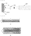
- FIG. 13 Images obtained by photographing surfaces of the large area liquid crystal devices according to Examples 2, 4 to 6 using an optical microscope (Eclipse L300ND by Nikon) are illustrated in FIG. 13 .
- the substrate was a PET film and the conductive layer includes ITO, as a result of calculating an energy density per unit area required to delaminate the conductive layer from the substrate, the energy density was 2.13 J/cm 2 or higher.
- the conductive layer may be separated from the substrate (PET film).
- FIG. 14 enlarged views of images obtained by photographing surfaces of the large area liquid crystal devices according to Examples 2, 4 to 6 using an optical microscope (Eclipse L300ND by Nikon) are illustrated in FIG. 14 .
- Example 6 in which the beam size was 9 mm, an interface of the delaminating area was not distinct as compared with Examples 2 to 5 in which the beam size was relatively small.
- the substrate was a PET film
- a 2.13 J or higher laser energy per unit area (cm 2 ) needed to be irradiated. It was further confirmed that in order to implement such a laser energy density, a laser having a beam diameter of less than 9 mm needed to be irradiated.
- a large area liquid crystal device in which a COP film having a thickness of 40 ⁇ m as a substrate, an ITO film having a thickness of 40 nm as a conductive layer, and an acrylate polymer based photo alignment film including a cinamate functional group having a thickness of 0.3 to 0.5 mm as a liquid crystal alignment film are sequentially provided was prepared.
- One area of the liquid crystal alignment film and the conductive layer was removed by irradiating a Q switching IR laser having a repetition frequency of 10 Hz, a pulse width of 6 ns, energy per pulse of 0.75 J, and beam diameters of 7.0 mm (Example 7) and 9.0 mm (Example 8) to the large area liquid crystal device using a Q switching IR laser (wavelength is 1064 nm and a product name is Q-smart 850) irradiating device to form a pattern in the large area liquid crystal device.
- a Q switching IR laser having a repetition frequency of 10 Hz, a pulse width of 6 ns, energy per pulse of 0.75 J, and beam diameters of 7.0 mm (Example 7) and 9.0 mm (Example 8) to the large area liquid crystal device using a Q switching IR laser (wavelength is 1064 nm and a product name is Q-smart 850) irradiating device to form a pattern in the large
- FIG. 15 Images obtained by photographing surfaces of the large area liquid crystal devices according to Examples 7 and 8 and using an optical microscope (Eclipse L300ND by Nikon) are illustrated in FIG. 15 .
- the substrate was a COP film and the conductive layer includes ITO, as a result of calculating an energy density per unit area required to delaminate the conductive layer from the substrate, the energy density was 1.1 J/cm 2 or higher.
- the conductive layer may be delaminated from the substrate (COP film) to form a pattern on the large area liquid crystal device.
- a pattern was formed on the large area liquid crystal device by the same method as Example 3 except that an aluminum etching mask having a thickness of 3.0 mm to which an aluminum foil having a thickness of 15 ⁇ m was attached with a general purpose double sided tape was provided in the larger size liquid crystal device before irradiating laser.
- a pattern was formed on the large area liquid crystal device by the same method as Example 7 except that an aluminum etching mask having a thickness of 3.0 mm to which an aluminum foil having a thickness of 15 ⁇ m is attached with a general purpose double sided tape was provided in the larger size liquid crystal device before irradiating the laser.
- FIG. 16 Images obtained by photographing surfaces of the large area liquid crystal devices according to Examples 3, 3-1, 7, and 7-1 using an optical microscope (Eclipse L300ND by Nikon) are illustrated in FIG. 16 .
- FIGS. 16A, 16B, 16C, and 16D are optical microscope images of surfaces of the large area liquid crystal devices according to Examples 3, 3-1, 7, and 7-1, respectively.
- upper portions represent portions which are not delaminated and lower portions represent portions where the substrate (PET film) is exposed and referring to FIGS. 16C and 16D , in FIGS. 16C and 16D , upper portions represent portions which are not delaminated and lower portions represent portions where the substrate (COP film) is exposed.
- FIG. 17 A digital camera image and an image photographed by an optical microscope (Eclipse L300ND by Nikon) of a surface of the large area liquid crystal device according to Example 7-1 are illustrated in FIG. 17 .
- a delaminated area and a non-delaminated area may be smoothly distinguished and when the etching mask is provided before irradiating the laser, the delaminated area and the non-delaminated area may be more distinctly distinguished.
Landscapes
- Physics & Mathematics (AREA)
- Optics & Photonics (AREA)
- Engineering & Computer Science (AREA)
- Nonlinear Science (AREA)
- Mechanical Engineering (AREA)
- Plasma & Fusion (AREA)
- Chemical & Material Sciences (AREA)
- General Physics & Mathematics (AREA)
- Crystallography & Structural Chemistry (AREA)
- Mathematical Physics (AREA)
- Chemical Kinetics & Catalysis (AREA)
- General Chemical & Material Sciences (AREA)
- Oil, Petroleum & Natural Gas (AREA)
- Spectroscopy & Molecular Physics (AREA)
- Ceramic Engineering (AREA)
- Liquid Crystal (AREA)
- Laser Beam Processing (AREA)
Abstract
Description
- This specification claims priority to and the benefit of Korean Patent Application No.
10-2016-0150575 - The present invention relates to a method of forming pattern for a large area liquid crystal device.
- Studies on a liquid crystal device which is applicable to a flexible electronic device product such as a display, a smart window, or a sunroof are continued.
- Specifically, a liquid crystal device includes a configuration in which a conductive layer is introduced above a substrate and a dielectric film, a liquid crystal alignment film having an electrical or electro-optical function, a gap spacer, etc are provided above and below the conductive layer. Further, the liquid crystal devices which are provided above and below liquid crystal are manufactured by a roll-to-roll (R2R) based continuous process of the related art.
- The conductive layer which is included in the liquid crystal device is provided with a metal oxide layer which is transparent and has conductivity above the substrate to form an electrical field for controlling an alignment of liquid crystal. The liquid crystal alignment film may impart an alignment function to the liquid crystal.
- In the step of processing the liquid crystal device according to the purpose of products, processes such as electrical short-circuiting and cutting are also important, but a process of imparting adhesiveness and durability of the liquid crystal device provided above/below the liquid crystal is specifically important.
- Further, in order to seal upper and lower liquid crystal devices above and below the liquid crystal, the liquid crystal alignment film has excellent adhesiveness with a sealant provided between the upper and lower liquid crystal devices. However, when the liquid crystal alignment film does not have excellent adhesiveness with the sealant, a process of exposing the substrate by selectively removing the liquid crystal alignment film and the conductive layer is additionally required.
- There is an inconvenient process in that a removal process such as photolithography, inkjet, and slot die (including an etching paste) methods of the related art needs to ensure an overlay precision of the conductive layer and the liquid crystal alignment film above the substrate. Further, there is a problem in that a cost of the facility for increasing a size is increased.
- Therefore, a process of separating the liquid crystal alignment film and the conductive layer using an etching process using a Galvano scanner and a laser beam which is focused with a diameter of several tens of micrometers has been tried. However, in this case, there were problems in that a removed cross-section is not smooth, residues are increased, and a producing speed is slow.
- Therefore, studies on a manufacturing method of a liquid crystal display from which one area of the liquid crystal alignment film and the conductive layer is removed with a high quality while ensuring a process economic efficiency through a relatively simple process are required.
- Korean Patent Application No.
10-2007-0030147 - The present invention has been made in an effort to provide a pattern forming a method of forming patterns for a large area liquid crystal device.
- However, technical problems of the present invention are not limited to the above-mentioned technical problems, and other technical problems, which are not mentioned above, can be clearly understood by those skilled in the art from the following descriptions.
- An exemplary embodiment of the present invention provides a method of forming patterns for a large area liquid crystal device, comprising: preparing a large area liquid crystal device which includes a substrate, a conductive layer provided on the substrate, and a liquid crystal alignment film provided on the conductive layer; and exposing one area of the substrate by delaminating one area of the conductive layer and the liquid crystal alignment film by irradiating a laser to the large area liquid crystal device; wherein the laser is irradiated from the liquid crystal alignment film toward the conductive layer and the laser is a Q switching IR laser having a beam diameter of 1 mm or larger and 16 mm or smaller and an energy per pulse of 0.05 J or higher and 2.5 J or lower.
- According to one exemplary embodiment of the present invention, a speed of a process of separating a liquid crystal alignment film and a conductive layer of a liquid crystal device is improved while minimizing damage of a substrate by irradiating a laser having a high energy, to improve productivity.
-
-
FIG. 1 illustrates a schematic diagram of a display device to which a liquid crystal device according to an exemplary embodiment of the present invention is applied. -
FIG. 2 schematically illustrates a method of forming patterns for a a liquid crystal device of the related art. -
FIG. 3 schematically illustrates a method of forming patterns for a large area liquid crystal device according to an exemplary embodiment of the present invention. -
FIG. 4 illustrates a laser irradiating method in a method of forming for a liquid crystal device of the related art. -
FIG. 5 illustrates a laser irradiating a method of forming patterns for a liquid crystal device according to an exemplary embodiment of the present invention. -
FIG. 6 illustrates a difference of a laser irradiating method in a method of forming patterns of the related art and a method of forming patterns according to an exemplary embodiment of the present invention in accordance with various surface shapes of a liquid crystal device. -
FIG. 7 illustrates a schematic view of a method of forming patterns for a large area liquid crystal device according to an exemplary embodiment of the present invention. -
FIG. 8 illustrates a laser irradiating method of Example 1 and Comparative Example 1. -
FIG. 9 illustrates a laser irradiating method of Comparative Example 1 in more detail. -
FIG. 10 illustrates a processing time in a predetermined line width of Example 1 and Comparative Example 1. -
FIG. 11 illustrates a laser irradiating method of Example 1 in more detail. -
FIG. 12 illustrates graphs of a minimum overlap and a highest scanning velocity according to a beam size in a predetermined line width of Example 1. -
FIG. 13 is an image obtained by photographing a surface of a large area liquid crystal device according to Examples 2, and 4 to 6 using an optical microscope. -
FIG. 14 is an enlarged view of an image obtained by photographing a surface of a large area liquid crystal device according to Examples 2 to 6 using an optical microscope. -
FIG. 15 is an image obtained by photographing a surface of a large area liquid crystal device according to Examples 7 and 8 using an optical microscope. -
FIG. 16 is an image obtained by photographing a surface of a large area liquid crystal device of Examples 3, 3-1, 7 and 7-1 using an optical microscope. -
FIG. 17 is a digital camera image of a surface of a large area liquid crystal device of Example 7-1 and an image obtained by photographing the surface using an optical microscope. -
- 10: substrate
- 20: Conductive layer
- 30: Liquid crystal alignment film
- 40: Liquid crystal
- 50: Spacer
- 60: Sealant
- 70: Polarizer
- 80: Linear stage
- 90: Etching mask
- 100: Large area liquid crystal device
- 200: Display device
- 300: Laser used for manufacturing method of related art
- 400: Q Switching laser
- In the specification, unless explicitly described to the contrary, the word "comprise or include" and variations such as "comprises or includes" or "comprising or including", will be understood to imply the inclusion of stated elements but not the exclusion of any other elements.
- In the specification, when specific numerical characters on the drawing are denoted by "A/B", it means that A and B are sequentially provided, and specifically, B is provided on A.
- Hereinafter, the present specification will be described in more detail.
- An exemplary embodiment of the present invention provides a method of forming patterns for a large area liquid crystal device, comprising: preparing a large area liquid crystal device which includes a substrate, a conductive layer provided on the substrate, and a liquid crystal alignment film provided on the conductive layer; and exposing one area of the substrate by delaminating one area of the conductive layer and the liquid crystal alignment film by irradiating a laser to the large area liquid crystal device; wherein the laser is irradiated from the liquid crystal alignment film toward the conductive layer and the laser is a Q switching IR laser having a beam diameter of 1 mm or larger and 16 mm or smaller and an energy per pulse of 0.05 J or higher and 2.5 J or lower.
- A schematic diagram of a
display device 200 to which a large area liquid crystal device on which a pattern is formed according to the exemplary embodiment of the present invention is applied is illustrated inFIG. 1 . - Referring to
FIG. 1 , upper and lower large arealiquid crystal devices 100 including asubstrate 10 in which one area of theconductive layer 20 and the liquidcrystal alignment film 30 is delaminated so that one area is exposed are prepared, and asealant 60 is interposed on the base substrate of the upper large area liquid crystal device and the lower large area liquid crystal device in which one area is exposed to seal the upper large area liquid crystal device and the lower large area liquid crystal device. - Further, a
liquid crystal 40 and aspacer 50 may be interposed on the conductive layer and the liquid crystal alignment film from which the one area is not removed, between the upper large area liquid crystal device and the lower large area liquid crystal device. Further, apolarizer 70 may be provided on one surface of one of the bonded upper large area liquid crystal device and lower large area liquid crystal device. - A method of forming patterns for a large area liquid crystal device according to an exemplary embodiment of the present invention includes a step of preparing a large area liquid crystal device which includes a substrate, a conductive layer provided on the substrate, and a liquid crystal alignment film provided on the conductive layer.
- According to an exemplary embodiment of the present invention, the large area liquid crystal device may include a substrate.
- According to the exemplary embodiment of the present invention, the base substrate may be a polycarbonate (PC) film, a colorless polyimide film, a polyethylene terephthalate film, or a cycle olefin polymer film. However, the base substrate is not limited thereto, but may be freely selected from polymers having a bending property and high adhesiveness with a sealant known in the art.
- According to an exemplary embodiment of the present invention, the large area liquid crystal device includes the substrate so that mechanical durability and structural flexibility of a large area liquid crystal device may be ensured. Specifically, the large area liquid crystal device includes the substrate so that a bending property is implemented.
- According to an exemplary embodiment of the present invention, a thickness of the substrate may be 40 µm or larger and 200 µm or smaller, specifically, 70 µm or larger and 200 µm or smaller, 40 µm or larger and 150 µm or smaller, or 70 µm or larger and 150 µm or smaller. More specifically, the thickness of the substrate may be 90 µm or larger and 150 µm or smaller, 70 µm or larger and 130 µm or smaller, or 90 µm or larger and 130 µm or smaller. However, the thickness is not limited thereto and may be freely adjusted according to a property of a product to which the large area liquid crystal device is applied.
- According to an exemplary embodiment of the present invention, the large area liquid crystal device may include a conductive layer provided on the substrate. The conductive layer may form an electric field for controlling an alignment of liquid crystal which may be applied on the liquid crystal alignment film and have electrical conductivity which may transfer charges supplied from the outside, and have a high surface energy.
- According to an exemplary embodiment of the present invention, the conductive layer may be an indium tin oxide (ITO) film. However, the conductive layer is not limited thereto, but a conductive layer, which may form an electric field to control the alignment of the liquid crystal, supply charges, and is known in the art, may be selected without limitation. Further, the conductive layer may be provided to have transparency and the transparency may be secured by applying various materials and methods of forming known in the art.
- According to an exemplary embodiment of the present invention, a thickness of the conductive layer may be 20 nm or larger and 100 nm or smaller, specifically, 30 nm or larger and 100 nm or smaller, 20 nm or larger and 80 nm or smaller, or 30 nm or larger and 80 nm or smaller. More specifically, the thickness of the conductive layer may be 40 nm or larger and 80 nm or smaller, 30 nm or larger and 70 nm or smaller, or 40 nm or larger and 70 nm or smaller. However, the thickness is not limited thereto and may be freely adjusted according to a property of a product to which the large area liquid crystal device is applied.
- The thickness of the conductive layer is much smaller than the thickness of the substrate so that damage to the substrate may be minimized by appropriately adjusting a condition of the laser which is irradiated during a process of separating the liquid crystal alignment film and the conductive layer.
- According to an exemplary embodiment of the present invention, the large area liquid crystal device may include a liquid crystal alignment film provided on the conductive layer. The large area liquid crystal device includes the liquid crystal alignment film on the conductive layer so that alignment of the liquid crystal provided on the liquid crystal alignment film may be controlled.
- According to an exemplary embodiment of the present invention, the liquid crystal alignment film may include at least one of a photo alignment film and a rubbing alignment film. Further, the liquid crystal alignment film may be provided to have a structure in which the photo alignment film and the rubbing alignment film are stacked.
- Specifically, the photo alignment film may control alignment of the liquid crystal applied on the liquid crystal alignment film by irradiating light. Further, the rubbing alignment film may control the alignment of the liquid crystal applied on the liquid crystal alignment film by a rubbing process which rotates a roller on the liquid crystal alignment film.
- According to the exemplary embodiment of the present invention, the photo alignment film may include a photo aligning compound. The photo aligning compound may be aligned to have directivity. Further, as the photo aligning compound, a compound which is orientationally ordered in a predetermined direction by irradiating light and aligns adjacent liquid crystal compounds in an aligned state in a predetermined direction and is known in the art may be selected without limitation.
- According to an exemplary embodiment of the present invention, the rubbing alignment film may be aligned to have directivity. Further, the rubbing alignment film may include a material which is aligned in a predetermined direction through a rubbing process, aligns adjacent liquid crystal compounds in the aligned state in a predetermined direction, and is known in the art without limitation.
- According to an exemplary embodiment of the present invention, the liquid crystal alignment film may include at least one of a monomolecular compound, a monomeric compound, an oligomeric compound, and a polymeric compound. However, the liquid crystal alignment film is not limited thereto and may be freely selected from compounds which can control the alignment of the liquid crystal and is known in the art.
- According to an exemplary embodiment of the present invention, a thickness of the liquid crystal alignment film may be 0.1 mm or larger and 1 mm or smaller, 0.1 mm or larger and 0.5 or smaller, 0.3 or larger and 1 mm or smaller, or 0.3 mm or larger and 0.5 mm or smaller. However, the thickness is not limited thereto and may be freely adjusted according to a property of a product to which the large area liquid crystal device is applied.
- Since a thickness range of the liquid crystal alignment film is relatively larger than the above-described thickness of the conductive layer, only when a condition of a laser which is irradiated during a process of delaminating the liquid crystal alignment film and the conductive layer by irradiating the laser is appropriately adjusted, the liquid crystal alignment film and the conductive layer may be delaminated and the damage of the substrate may be minimized.
- According to an exemplary embodiment of the present invention, the method of forming patterns for the large area liquid crystal device includes a step of exposing one area of the substrate by delaminating one area of the conductive layer and the liquid crystal alignment film by irradiating laser onto the large area liquid crystal device.
- According to an exemplary embodiment of the present invention, the laser may be irradiated from the liquid crystal alignment film toward the conductive layer.
- According to an exemplary embodiment of the present invention, a beam diameter of the laser may be 1 mm or larger and 16 mm or smaller, 1 mm or larger and 9 mm or smaller, 1 mm or larger and 8 mm or smaller, 4 mm or larger and 16 mm or smaller, 4 mm or larger and 9 mm or smaller, 4 mm or larger and 8 mm or smaller, 5 mm or larger and 16 mm or smaller, 5 mm or larger and 9 mm or smaller, or 5 mm or larger and 8 mm or smaller.
- Within the above range, efficiency of a pattern forming process of a large area liquid crystal device may be improved while minimizing damage of the substrate and increasing a separating process speed. Specifically, when the beam diameter does not reach the above range, the irradiated laser is excessively overlapped which causes damage to the substrate and a decrease of a delaminated area so that it is difficult to perform delamination at high speed. Further, when the beam diameter exceeds the range, a pulse energy density of the irradiated laser is decreased so that the liquid crystal alignment film and the conductive layer are not sufficiently delaminated.
- Further, the beam diameter of the laser may be adjusted by providing a lens between the large area liquid crystal device and the laser. When the diameter of the laser beam is adjusted using the lens, it is necessary to consider an energy density according to a diameter of the beam. Further, since the energy density of the irradiated laser may vary according to adhesiveness between a material to be separated and the base substrate, a process of optimizing a delaminating property according to a speed of a delaminating process and the energy density may be requested.
- According to an exemplary embodiment of the present invention, an energy per a purse of the laser may be 0.05 J or higher and 2.5 J or lower, 0.05 J or higher and 1.5 or lower, 0.3 J or higher and 2.5 J or lower, or 0.3 J or higher and 1.5 J or lower.
- Within the above-described range, the liquid crystal alignment film and the conductive layer may be delaminated while minimizing damage of the substrate. Specifically, when the energy per pulse of the laser is lower than the above-described range, the liquid crystal alignment film and the conductive layer are not sufficiently delaminated and when the energy per pulse of the laser exceeds the above-described range, the substrate may be damaged due to excessive energy.
- According to an exemplary embodiment of the present invention, the laser may be a Q switching IR laser.
- In the present specification, Q switching refers to one of the techniques for creating a laser light pulse output beam. According to the Q switching method, a laser resonator is excited to a state when a Q value of the laser resonator is reduced to accumulate a sufficient energy in a laser medium and then when the Q value is rapidly increased, oscillation starts so that the accumulated energy is discharged as a quick and sharp light pulse. Further, the Q switching method may be used to obtain a light pulse having a high peak output and a narrow width.
- Further, when the Q switching is used for a glass laser or carbon dioxide (CO2) laser, a high energy output may be obtained.
- According to an exemplary embodiment of the present invention, the laser may be a laser obtained by applying the Q switching to a Nd:YAG (neodymium-doped yttrium aluminum garnet) laser.
- According to an exemplary embodiment of the present invention, the laser may be an IR laser. Specifically, a wavelength of the laser may be 1064 nm.
- In the specification, the IR laser may refer to a laser having a wavelength of an irradiated laser in an infrared (IR) range.
- According to an exemplary embodiment of the present invention, the laser may be irradiated using a normal objective lens such that an energy density of the laser which is irradiated to the large area liquid crystal device per unit area may be 1.0 J/cm2 or higher and 3.0 J/cm2 or lower. When the above-mentioned energy density per unit area is satisfied, the conductive layer and the liquid crystal alignment film may be sufficiently delaminated.
- However, the energy density of the laser per unit area may vary according to a type of a substrate on which the conductive layer is provided. For example, when the conductive layer including ITO is formed on a COP film substrate, the energy density of the laser may be 1.1 J/cm2 or higher. When a conductive layer including ITO is formed on a PET film substrate, the energy density of the laser may be 2.1 J/cm2 or higher.
- According to an exemplary embodiment of the present invention, a repetition frequency of the laser may be 1 Hz or higher or 10 Hz or lower.
- Within the above-described range, a high process speed of the pattern forming process of the large area liquid crystal device may be implemented. That is, according to the range of the repetition frequency, a collision frequency of an irradiated laser per hour is relatively low. However, a laser having a high energy is intermittently irradiated to minimize a time taken to separate the conductive layer and the liquid crystal alignment film.
- In the specification, the term "repetition frequency of laser" may refer to a frequency of laser which oscillates or stops in time, that is, the number of collisions per time with an irradiated object of laser.
- According to an exemplary embodiment of the present invention, a pulse width of the laser may be 1.0 ns or longer and 10.0 ns or shorter, 1.0 ns or longer and 8.0 ns or shorter, 5.0 ns or longer and 10.0 ns or shorter, or 6.0 ns or longer and 8.0 ns or shorter.
- Within the above-described range, the liquid crystal alignment film and the conductive layer may be delaminated while minimizing damage of the substrate. Specifically, within the above-described range, a thermal energy by laser irradiation is smoothly transferred so that the liquid crystal alignment film and the conductive layer may be rapidly delaminated.
- In the specification, the term "pulse width of laser" may refer to an interval of time at which an amplitude is half at a rising time and a falling time of the pulse laser which oscillates and stops in time.
-
FIG. 2 schematically illustrates a method of forming patterns for a liquid crystal device of the related art. Referring toFIG. 2 , according to the related art method, a laser having a power of several tens of Watts is focused to a large arealiquid crystal device 100 in which asubstrate 10, aconductive layer 20, and a liquidcrystal alignment film 30 are sequentially provided to rapidly scan alaser 300 having a beam diameter of several tens of µm with a high repetition frequency to repeatedly hatch through overlapping between local areas. -
FIG. 3 schematically illustrates a method of forming patterns for a large area liquid crystal device according to an exemplary embodiment of the present invention. - Specifically, referring to
FIG. 3 , differently from the related art method, a method of forming patterns for a large area liquid crystal device according to an exemplary embodiment of the present invention irradiates alaser 400 having a beam diameter of a relatively large mm unit and a higher energy per pulse to a large arealiquid crystal device 100 in which asubstrate 10, aconductive layer 20, and a liquidcrystal alignment film 30 are sequentially provided to delaminate a large area at one time, so that it is advantageous for rapid delamination. - Further,
FIG. 4 illustrates a laser irradiating method in a method of forming patterns for a liquid crystal device of the related art. Specifically,FIG. 4 illustrates one of the methods known in the related art as one example. - Referring to
FIG. 4 , in order to delaminate the conductive layer and the liquid crystal alignment film formed on a circular substrate having a diameter of 6 mm, the delamination process is performed with a high repetition frequency of 40 kHz, a high scanning velocity of 2000 mm/s, and a small laser beam diameter of 40 µm. In this case, a time (tact time) taken to perform a process of forming a pattern in a large area liquid crystal device was calculated to be 0.37 s. Further, experimentally, the tact time was 1.06 s when the laser is irradiated in a parallel direction and was 0.52 s when the laser is irradiated in bidirectionally crossing directions. - Further, when the delaminating process was performed on the conductive layer and the liquid crystal alignment film formed on a square substrate having one side of 4 mm in length under the same condition, the tact time was calculated to be 0.21 s. Further, experimentally, the tact time was 0.63 s when the laser was irradiated in a parallel direction and was 0.32 s when the laser was irradiated in bidirectionally crossing directions.
- In the meantime, a difference between the experimental value and the calculated value is caused by inertia, an acceleration/reduction speed interval, a hatching interval, and direction setting according to an operation of a driving Galvano mirror of a laser irradiating device.
-
FIG. 5 illustrates a laser irradiating method in an exemplary embodiment of the present invention.FIG. 5 illustrates one example of a method of forming patterns for a large area liquid crystal device according to an exemplary embodiment of the present invention. - Referring to
FIG. 5 , according to method of forming patterns according to an exemplary embodiment of the present invention, in order to delaminate the conductive layer and the liquid crystal alignment film formed on the substrate, the delaminating process is performed with a laser having a low repetition frequency of 10 Hz and a large laser beam diameter of 6 mm. - In this case, both the tact time for a circular substrate having a diameter of 6 mm and the tact time for the square substrate having one side of 4 mm in length are 0.1 s.
- Therefore, the method of forming patterns for a liquid crystal device according to an exemplary embodiment of the present invention may advantageously secure a processing speed which is significantly faster than that of the related art.
- Further, the method of forming patterns for a large area liquid crystal device according to an exemplary embodiment of the present invention may advantageously secure a processing speed even when a liquid crystal device having various surface shapes is manufactured.
-
FIG. 6 illustrates a difference of a laser irradiating method in a method of forming patterns according to the related art and a method of forming patterns according to an exemplary embodiment of the present invention in accordance with various surface shapes of a liquid crystal device. - Referring to
FIG. 6A , it is confirmed that according to the method of forming patterns of the related art, the laser needs to be irradiated to a liquid crystal device having a large angle of a curved line and an intersection line several times or more and a delaminating direction needs to be changed several times, so that it takes a long time for a delaminating process. - In contrast, referring to
FIG. 6B , it is confirmed that the delaminating process may be relatively easily performed by irradiating the laser several times according to the method of forming patterns of the exemplary embodiment of the present invention. - According to the exemplary embodiment of the present invention, the step of exposing one area of the substrate may be performed by volume expansion.
- According to the exemplary embodiment of the present invention, the step of exposing one area of the substrate is performed with volume expansion driven delamination of the conductive layer from the substrate.
- Specifically, in the step of exposing one area of the substrate, the conductive layer is delaminated from the substrate due to the volume expansion so that the conductive layer and the liquid crystal alignment film provided on the conductive layer are separated from the substrate.
- When the laser is irradiated to the large area liquid crystal device, the substrate transmits the laser and the conductive layer may absorb the laser.
- As the conductive layer absorbs the laser, volume expansion occurs due to instantaneous thermal energy supply and the conductive layer may be delaminated from the substrate by the volume expansion.
- When the laser is irradiated to the conductive layer provided on the substrate, the energy of the irradiated laser is absorbed by the conductive layer and thus a temperature of the conductive layer instantaneously rises, so that rapid thermal expansion of the conductive layer is caused.
- Thermal elastic force of the conductive layer is generated due to the thermal expansion and the thermal elastic force acts as a force for separating the conductive layer from the substrate. The conductive layer is mainly coupled to the substrate by a Van Der Vaals force. As soon as the thermal electric force exceeds the Van Der Vaals force, the conductive layer may be delaminated from the substrate.
- A delaminating force caused by the thermal elastic force is proportional to an intensity of energy of the irradiated laser and is inversely proportional to a square of a pulse width of the irradiated laser as represented in the following
Equation 1. That is, the delaminating force varies depending on how fast a laser having high energy is irradiated, rather than an absolute value of the thermal expansion, so that the shorter the pulse width of the laser, the stronger the delaminating force.
- In
Equation 1 above, F refers to a delaminating force of the conductive layer from the base substrate, I refers to an intensity of the irradiated laser, and tp refers to a pulse width of the irradiated laser. - A change of volume according to a temperature change may be quantified by a coefficient of thermal expansion (CTE) and may vary according to a thickness of each component, a manufacturing company, a product quality, a pulse width of an irradiated laser, and an energy amount in accordance with the laser irradiation. Further, when the coefficient of thermal expansion of the substrate is higher than the coefficient of thermal expansion of the conductive layer, the conductive layer and the liquid crystal alignment film may be smoothly delaminated off by irradiating the laser.
- According to an exemplary embodiment of the present invention, a step of exposing one area of the substrate is performed by further providing an etching mask on the large area liquid crystal device and then removing an etching mask together with residues of the etched liquid crystal alignment film and conductive layer by irradiating the laser.
- That is, after disposing the liquid crystal alignment film on the large area liquid crystal device, when the laser is irradiated to delaminate the conductive layer and the liquid crystal alignment film from the substrate, a shape of the separated cross-section may be smoothly formed without being bent.
- Further, the etching mask may be freely selected from etching masks known in the art and a type thereof is not limited.
-
FIG. 7 illustrates a schematic diagram of a method of forming patterns for a large area liquid crystal device according to an exemplary embodiment of the present invention. - Specifically, referring to
FIG. 7 , a method of forming patterns according to an exemplary embodiment of the present invention prepares a lamination in which asubstrate 10, aconductive layer 20, and a liquidcrystal alignment film 30 are sequentially provided on alinear stage 80, provides anetching mask 90 on the large area liquid crystal device, and then irradiates a Q switchingIR laser 400 from the liquid crystal alignment film toward the conductive layer to separate one area of the conductive layer and the liquid crystal alignment film to expose one area of the substrate. In this case, alens 401 is provided between the Q switching IR laser and the large area liquid crystal device to adjust a beam diameter of the irradiated laser. - According to an exemplary embodiment of the present invention, the large area liquid crystal device may be used for a automobile sunroof, a smart window, a privacy window, or a variable transmittance film. That is, the method of forming patterns for a large area liquid crystal device according to an exemplary embodiment of the present invention may be applied to large area liquid crystal devices having various sizes.
- Hereinafter, the present invention will be described in detail through Examples. However, the Examples according to the present invention may be modified in various forms, and the scope of the present invention is not interpreted as being limited to the Examples described below. The Examples of the present specification are provided for more completely explaining the present invention to those skilled in the art.
- A large area liquid crystal device in which a PET film having a thickness of 125 µm as a substrate, an ITO film having a thickness of 40 nm as a conductive layer, and an acrylate polymer based photo alignment film including a cinamate functional group having a thickness of 0.3 to 0.5 mm as a liquid crystal alignment film are sequentially provided was prepared.
- One area of the liquid crystal alignment film and the conductive layer was removed by irradiating Yb fiber laser (70 W, produced by IPG Photonics Corporation) having an etching interval of 38 µm, a repetition frequency of 40 kHz, a scanning velocity of 2000 mm/s, and a beam diameter of 40 µm to the large area liquid crystal device to form a pattern in the large area liquid crystal device.
- One area of the liquid crystal alignment film and the conductive layer was removed by irradiating a Q switching IR laser having a repetition frequency of 10 Hz, a pulse width of 6 ns, energy per pulse of 0.85 J, and a beam diameter of 6 mm to the same large area liquid crystal device prepared in Comparative Example 1 using a Q switching IR laser (wavelength is 1064 nm and a product name is Q-smart 850) irradiating device to form a pattern in the large area liquid crystal device.
- In this case, the beam diameter was adjusted using a lens and an aluminum etching mask having a thickness of 3.0 mm to which an aluminum foil having a thickness of 15 µm was attached with a general purpose double sided tape was provided to the large area liquid crystal device before irradiating the laser.
-
FIG. 8 illustrates a laser irradiating method of Example 1 and Comparative Example 1. -
FIG. 8A illustrates a rectangular separating area having a predetermined length L and a line width W according to Comparative Example 1 andFIG. 8B illustrates that a rectangular separating area having a predetermined length L and a line width W according to Example 1 is divided by the aluminum etching mask. - Further,
FIG. 9 illustrates a laser irradiating method of Comparative Example 1 in more detail. An irradiating direction of the laser was changed along a moving direction of the line width W while moving theYb fiber laser 30 used in Comparative Example 1 in a length (L) direction to perform a delaminating process. - Tact times according to line widths (W = 2 mm, 3 mm, 4 mm, and 5 mm) of the delaminating process of Example 1 and Comparative Example 1 were calculated.
- Specifically, in Comparative Example 1, a transferring time (approximately, 2.5 seconds) of the Yb fiber laser was considered and a tact time of the delaminating process of Comparative Example 1 was calculated by "number of repetitions X time for one-time scanning" as represented in the following
Equation 2. - The "number of repetitions" was represented by "length/etching interval (L/Whatching) in
Equation 2 and the "time for one-time scanning" was represented by "line width/scanning velocity (w/vscan) inEquation 2.
- Further, the tact time of the delaminating process of
Equation 1 was "distance between single emitted beams in consideration of delaminating width/repetition velocity" and calculated as represented inEquation 3. - The "distance between single emitted beams in consideration of delaminating width" was denoted by "L" in
Equation 3 and the "repetition velocity" was represented by "f· (D2 - W2)0.5" inEquation 3.
- In
Equation 3, f denotes a repetition frequency of laser and D denotes a beam diameter of the laser. - A tact time for the process according to a length L of a delaminating area in a predetermined line width w of Example 1 and Comparative Example 1 is illustrated in
FIG. 10 and a tact time for the process when a length of the delaminating area is 1000 mm is specifically represented in Table 1.[Table 1] L=1,000 mm W=2mm W=3mm W=4mm W=5mm Comparative Example 1 84.3 s 97.94 s 114.10 s 120.72 s Example 1 17.68 s 19.25 s 22.36 s 30.15 s - Referring to
FIG. 10 , it was confirmed that in Example 1, a tact time for a process for obtaining a delaminating area with a predetermined line width was not significantly increased even though a length of the delaminating area was increased but in Comparative Example 1, as the length of the delaminating area was increased, a tact time for a process was significantly increased. - Also in Table 1 when the length of the delaminating area is 1000 mm, it was confirmed that a tact time according to the same line width in Example 1 was much shorter than that of Comparative Example (approximately 4 times to 5.1 times reduced).
- By doing this, it was confirmed that when the laser was irradiated with the condition according to the exemplary embodiment of the present invention, a time for a pattern forming process of a large area liquid crystal device was significantly shortened and thus economic efficiency in the manufacturing process of a liquid crystal device may be secured.
- Further, it was confirmed that in Example 1, a laser having a relatively large beam diameter was irradiated so that a laser scanning velocity and an overlap between beams needed to be optimized. Specifically, it was confirmed that the overlap of the laser according to the line width W and the beam diameter D needed to be minimized and the laser scanning velocity needed to be maximized.
- Specifically,
FIG. 11 illustrates a schematic diagram of an overlap of a laser beam when a laser is irradiated similarly to Example 1. - Referring to
FIG. 11 , a line width W is represented by 2r·sinθ and a laser repetition interval d is represented by 2r·cosθ. By doing this, the laser repetition interval d may be represented by "(D2 - W2)0.5". - By doing this, a ratio of an overlap area between irradiated laser beams (overlap, unit is %) may be represented by "1 - (d/D)
X 100" and when the above-described equation of laser repetition interval d is applied, the overlap may be represented by "[1 - {(D2 - W2)0.5/D}]X 100". - Further, the scanning velocity v of the laser may be obtained by "laser repetition interval X laser repetition frequency" so that the scanning velocity of the laser may be obtained through an equation represented by "f· (D2 - W2)0.5.
- Therefore, when a line width to be delaminated is determined, a minimum overlap between laser beams for implementing the line width and a highest scanning velocity at this time may be obtained as the overlap and the scanning velocity of the laser.
- A graph of the minimum overlap according to the beam size and the scanning velocity according to the above-described method is illustrated in
FIG. 12 . - Referring to
FIG. 12 , when the line width of the delaminating area is determined, the minimum overlap and the highest scanning velocity may be obtained according to a diameter of an irradiated beam. - In
FIG. 12 , for example, when a line width is determined to be 5 mm, if the diameter of the irradiated beam is 8 mm, it was confirmed that the minimum overlap is approximately 25% and the maximum scanning velocity is approximately 60 mm/s. - A large area liquid crystal device in which a PET film having a thickness of 125 µm as a substrate, an ITO film having a thickness of 40 nm as a conductive layer, and an acrylate polymer based photo alignment film including a cinamate functional group having a thickness of 0.3 to 0.5 mm as a liquid crystal alignment film are sequentially provided was prepared.
- One area of the liquid crystal alignment film and the conductive layer was removed by irradiating a Q switching IR laser having a repetition frequency of 10 Hz, a pulse width of 6 ns, energy per pulse of 0.75 J, and beam diameters of 4.0 mm (Example 2), 5.0 mm (Example 3), 6.0 mm (Example 4), 7.0 mm (Example 5), and 9.0 mm (Example 6) to the large area liquid crystal device using a Q switching IR laser (wavelength is 1064 nm and a product name is Q-smart 850) irradiating device to form a pattern in the large area liquid crystal device.
- Images obtained by photographing surfaces of the large area liquid crystal devices according to Examples 2, 4 to 6 using an optical microscope (Eclipse L300ND by Nikon) are illustrated in
FIG. 13 . - Referring to
FIG. 13 , it was confirmed that an area where the liquid crystal alignment film and the conductive layer were delaminated by irradiating the Q switching IR laser and an area where the liquid crystal alignment film and the conductive layer were not delaminated were distinctly distinguished (distinguished by a dotted line circle ofFIG. 13 ). Therefore, it was confirmed that only when the laser having a range of a beam diameter according to the exemplary embodiment of the present invention was irradiated, the liquid crystal alignment film and the conductive layer were sufficiently delaminated while reducing damage of the substrate. It was further confirmed that in Example 6 in which the irradiated beam diameter was 9 mm, the conductive layer was not satisfactorily delaminated as compared with Examples 2 to 5 in which the beam size was relatively small. - Further, it was confirmed that when the substrate was a PET film and the conductive layer includes ITO, as a result of calculating an energy density per unit area required to delaminate the conductive layer from the substrate, the energy density was 2.13 J/cm2 or higher.
- By doing this, it was confirmed that only when a Q switching IR laser having a minimum energy density of 2.13 J/cm2 was irradiated, the conductive layer may be separated from the substrate (PET film).
- Further, enlarged views of images obtained by photographing surfaces of the large area liquid crystal devices according to Examples 2, 4 to 6 using an optical microscope (Eclipse L300ND by Nikon) are illustrated in
FIG. 14 . - Referring to
FIG. 14 , it was confirmed that in Example 6 in which the beam size was 9 mm, an interface of the delaminating area was not distinct as compared with Examples 2 to 5 in which the beam size was relatively small. - In summary, when the substrate was a PET film, it was confirmed that in order to delaminate the ITO conductive layer from the substrate, a 2.13 J or higher laser energy per unit area (cm2) needed to be irradiated. It was further confirmed that in order to implement such a laser energy density, a laser having a beam diameter of less than 9 mm needed to be irradiated.
- A large area liquid crystal device in which a COP film having a thickness of 40 µm as a substrate, an ITO film having a thickness of 40 nm as a conductive layer, and an acrylate polymer based photo alignment film including a cinamate functional group having a thickness of 0.3 to 0.5 mm as a liquid crystal alignment film are sequentially provided was prepared.
- One area of the liquid crystal alignment film and the conductive layer was removed by irradiating a Q switching IR laser having a repetition frequency of 10 Hz, a pulse width of 6 ns, energy per pulse of 0.75 J, and beam diameters of 7.0 mm (Example 7) and 9.0 mm (Example 8) to the large area liquid crystal device using a Q switching IR laser (wavelength is 1064 nm and a product name is Q-smart 850) irradiating device to form a pattern in the large area liquid crystal device.
- Images obtained by photographing surfaces of the large area liquid crystal devices according to Examples 7 and 8 and using an optical microscope (Eclipse L300ND by Nikon) are illustrated in
FIG. 15 . - Referring to
FIG. 15 , it was confirmed that an area where the liquid crystal alignment film and the conductive layer were delaminated by irradiating the Q switching IR laser and an area where the liquid crystal alignment film and the conductive layer were not delaminated were distinctly distinguished (distinguished by a dotted line circle ofFIG. 15 ). Therefore, it was confirmed that only when the laser having a range of a beam diameter according to the exemplary embodiment of the present invention was irradiated, the liquid crystal alignment film and the conductive layer were sufficiently delaminated while reducing damage of the substrate. - Further, in this case, it was confirmed that when the substrate was a COP film and the conductive layer includes ITO, as a result of calculating an energy density per unit area required to delaminate the conductive layer from the substrate, the energy density was 1.1 J/cm2 or higher. By doing this, it was confirmed that only when a Q switching IR laser having a minimum energy density of 1.1 J/cm2 was irradiated, the conductive layer may be delaminated from the substrate (COP film) to form a pattern on the large area liquid crystal device.
- A pattern was formed on the large area liquid crystal device by the same method as Example 3 except that an aluminum etching mask having a thickness of 3.0 mm to which an aluminum foil having a thickness of 15 µm was attached with a general purpose double sided tape was provided in the larger size liquid crystal device before irradiating laser.
- A pattern was formed on the large area liquid crystal device by the same method as Example 7 except that an aluminum etching mask having a thickness of 3.0 mm to which an aluminum foil having a thickness of 15 µm is attached with a general purpose double sided tape was provided in the larger size liquid crystal device before irradiating the laser.
- Images obtained by photographing surfaces of the large area liquid crystal devices according to Examples 3, 3-1, 7, and 7-1 using an optical microscope (Eclipse L300ND by Nikon) are illustrated in
FIG. 16 . - Specifically,
FIGS. 16A, 16B, 16C, and 16D are optical microscope images of surfaces of the large area liquid crystal devices according to Examples 3, 3-1, 7, and 7-1, respectively. - Referring to
FIGS. 16A and 16B , inFIGS. 16A and 16B , upper portions represent portions which are not delaminated and lower portions represent portions where the substrate (PET film) is exposed and referring toFIGS. 16C and 16D , inFIGS. 16C and 16D , upper portions represent portions which are not delaminated and lower portions represent portions where the substrate (COP film) is exposed. - Referring to
FIGS. 16A and 16B , it was confirmed that an etched area of the surface of the large area liquid crystal device including an etching mask according to Example 3-1 was smoother than an etched area of the surface of the large area liquid crystal device which did not include an etching mask according to Example 3. - Further, referring to
FIGS. 16C and 16D , it was confirmed that an etched area of the surface of the large area liquid crystal device including an etching mask according to Example 7-1 was smoother than an etched area of the surface of the large area liquid crystal device which does not include an etching mask according to Example 7. - A digital camera image and an image photographed by an optical microscope (Eclipse L300ND by Nikon) of a surface of the large area liquid crystal device according to Example 7-1 are illustrated in
FIG. 17 . - Referring to
FIG. 17 , it can be visually confirmed that an etched area of the surface of the large area liquid crystal device including an etching mask according to Example 7-1 is smoothly formed, which may be more apparent from the image photographed by the optical microscope by enlarging the surface of the large area liquid crystal device. - In summary, it is understood that when the conductive layer and the liquid crystal alignment film are delaminated under the laser irradiating condition according to an exemplary embodiment of the present invention, a delaminated area and a non-delaminated area may be smoothly distinguished and when the etching mask is provided before irradiating the laser, the delaminated area and the non-delaminated area may be more distinctly distinguished.
Claims (11)
- A method of forming patterns for a large area liquid crystal device, comprising:preparing a large area liquid crystal device which includes a substrate, a conductive layer provided on the substrate, and a liquid crystal alignment film provided on the conductive layer; andexposing one area of the substrate by delaminating one area of the conductive layer and the liquid crystal alignment film by irradiating a laser to the large area liquid crystal device;wherein the laser is irradiated from the liquid crystal alignment film toward the conductive layer and the laser is a Q switching IR laser having a beam diameter of 1 mm or larger and 16 mm or smaller and an energy per pulse of 0.05 J or higher and 2.5 J or lower.
- The method of claim 1, wherein the substrate is a polycarbonate film, a colorless polyimide film, a polyethylene terephthalate film, or a cycle olefin polymer film.
- The method of claim 1, wherein the conductive layer is an indium tin oxide film.
- The method of claim 1, wherein the liquid crystal alignment film includes at least one of a monomolecular compound, a monomeric compound, an oligomeric compound, and a polymeric compound.
- The method of claim 1, wherein the energy per pulse of the laser is 0.3 J or higher and 1.5 J or lower.
- The method of claim 1, wherein the beam diameter of the laser is 4 mm or larger and 9 mm or smaller.
- The method of claim 1, wherein a repetition frequency of the laser is 1 Hz or higher and 10 Hz or lower.
- The method of claim 1, wherein a pulse width of the laser is 1.0 ns or longer and 10.0 ns or shorter.
- The method of claim 1, wherein the exposing one area of the substrate is performed with volume expansion driven delamination of the conductive layer from the substrate.
- The method of claim 1, wherein the exposing one area of the substrate is performed by further providing an etching mask on the large area liquid crystal device and then removing the etching mask together with residues of the etched liquid crystal alignment film and conductive layer by irradiating the laser.
- The method of claim 1, wherein the large area liquid crystal device is used for an automobile sunroof, a smart window, a privacy window, or a variable transmittance film.
Applications Claiming Priority (2)
| Application Number | Priority Date | Filing Date | Title |
|---|---|---|---|
| KR20160150575 | 2016-11-11 | ||
| PCT/KR2017/012753 WO2018088853A1 (en) | 2016-11-11 | 2017-11-10 | Method for forming pattern of large area liquid crystal device |
Publications (3)
| Publication Number | Publication Date |
|---|---|
| EP3539773A1 true EP3539773A1 (en) | 2019-09-18 |
| EP3539773A4 EP3539773A4 (en) | 2019-11-06 |
| EP3539773B1 EP3539773B1 (en) | 2020-09-16 |
Family
ID=62110780
Family Applications (1)
| Application Number | Title | Priority Date | Filing Date |
|---|---|---|---|
| EP17869356.0A Active EP3539773B1 (en) | 2016-11-11 | 2017-11-10 | Method of forming petterns for a large area liquid crystal device |
Country Status (6)
| Country | Link |
|---|---|
| US (1) | US10730147B2 (en) |
| EP (1) | EP3539773B1 (en) |
| JP (1) | JP6714890B2 (en) |
| KR (1) | KR102029690B1 (en) |
| CN (1) | CN109922962B (en) |
| WO (1) | WO2018088853A1 (en) |
Family Cites Families (19)
| Publication number | Priority date | Publication date | Assignee | Title |
|---|---|---|---|---|
| US4937129A (en) | 1988-01-06 | 1990-06-26 | Semiconductor Energy Laboratory Co., Ltd. | Thin film pattern structure formed on a glass substrate |
| JPH0645483B2 (en) | 1988-01-06 | 1994-06-15 | 株式会社半導体エネルギー研究所 | Substrate for liquid crystal display device and manufacturing method thereof |
| JP3293136B2 (en) | 1993-06-04 | 2002-06-17 | セイコーエプソン株式会社 | Laser processing apparatus and laser processing method |
| US6300594B1 (en) * | 1998-02-19 | 2001-10-09 | Ricoh Microelectronics Company, Ltd. | Method and apparatus for machining an electrically conductive film |
| US6203952B1 (en) | 1999-01-14 | 2001-03-20 | 3M Innovative Properties Company | Imaged article on polymeric substrate |
| JP2003154478A (en) * | 2002-07-29 | 2003-05-27 | Seiko Epson Corp | Laser beam machining device and method, and liquid crystal panel |
| JP2007080311A (en) | 2005-09-12 | 2007-03-29 | Sony Corp | Storage device and semiconductor device |
| JP2007212666A (en) | 2006-02-08 | 2007-08-23 | Sony Corp | Method for patterning alignment layer |
| US7867907B2 (en) * | 2006-10-17 | 2011-01-11 | Semiconductor Energy Laboratory Co., Ltd. | Method for manufacturing semiconductor device |
| KR100838344B1 (en) * | 2007-03-28 | 2008-06-17 | 연세대학교 산학협력단 | Method for patterning nanoparticles by pulsed laser |
| JP5067862B2 (en) * | 2007-11-19 | 2012-11-07 | スタンレー電気株式会社 | Liquid crystal display device and manufacturing method thereof |
| JPWO2009128359A1 (en) | 2008-04-17 | 2011-08-04 | 旭硝子株式会社 | GLASS LAMINATE, PANEL FOR DISPLAY DEVICE WITH SUPPORT AND METHOD FOR PRODUCING THEM |
| KR101039549B1 (en) | 2009-04-03 | 2011-06-09 | 연세대학교 산학협력단 | Method for direct-laser patterning of thin film |
| KR20110060265A (en) | 2009-11-30 | 2011-06-08 | 동우 화인켐 주식회사 | Method for peeling a polarizing plate from a liquid crystal cell |
| JP5685567B2 (en) | 2012-09-28 | 2015-03-18 | 株式会社東芝 | Manufacturing method of display device |
| KR102074168B1 (en) | 2013-09-10 | 2020-02-06 | 동우 화인켐 주식회사 | Hybrid touch sensing electrode and preparing method thereof |
| KR101558320B1 (en) | 2014-01-28 | 2015-10-06 | 주식회사 아이카이스트 | Method of patterning for transparent electrode |
| JP5800304B2 (en) * | 2014-07-22 | 2015-10-28 | 信越ポリマー株式会社 | Input device |
| KR101726265B1 (en) | 2014-10-27 | 2017-04-12 | 주식회사 엘지화학 | Method for peeling a polarizing plate from a liquid crystal pannel |
-
2017
- 2017-11-10 US US16/349,254 patent/US10730147B2/en active Active
- 2017-11-10 EP EP17869356.0A patent/EP3539773B1/en active Active
- 2017-11-10 KR KR1020170149779A patent/KR102029690B1/en active IP Right Grant
- 2017-11-10 WO PCT/KR2017/012753 patent/WO2018088853A1/en unknown
- 2017-11-10 JP JP2019518998A patent/JP6714890B2/en active Active
- 2017-11-10 CN CN201780068537.3A patent/CN109922962B/en active Active
Also Published As
| Publication number | Publication date |
|---|---|
| CN109922962B (en) | 2021-04-27 |
| US20190271868A1 (en) | 2019-09-05 |
| KR20180053257A (en) | 2018-05-21 |
| CN109922962A (en) | 2019-06-21 |
| WO2018088853A1 (en) | 2018-05-17 |
| KR102029690B1 (en) | 2019-10-10 |
| JP6714890B2 (en) | 2020-07-01 |
| EP3539773B1 (en) | 2020-09-16 |
| EP3539773A4 (en) | 2019-11-06 |
| JP2019533828A (en) | 2019-11-21 |
| US10730147B2 (en) | 2020-08-04 |
Similar Documents
| Publication | Publication Date | Title |
|---|---|---|
| TWI583476B (en) | Method for producing an optical display ?device and production system of an optical display device | |
| US4734550A (en) | Laser processing method | |
| KR101262173B1 (en) | Conductive film patterning method, and fabricating method of flexible display device | |
| CN102665999B (en) | Laser processing method | |
| JP5025158B2 (en) | Laser processing method and apparatus | |
| JP5905274B2 (en) | Manufacturing method of semiconductor device | |
| CN111386172B (en) | Laser processing method for plastic film and plastic film | |
| US20170313617A1 (en) | Method and apparatus for laser-cutting of transparent materials | |
| JP2004042140A (en) | Process and device for removal of thin film | |
| JP2007212666A (en) | Method for patterning alignment layer | |
| KR101172791B1 (en) | Laser lift-off method and laser lift-off apparatus | |
| CN105102171B (en) | The manufacture device of optical member adhering body | |
| KR102527033B1 (en) | Wafer processing method | |
| EP3539773B1 (en) | Method of forming petterns for a large area liquid crystal device | |
| JP5584560B2 (en) | Laser scribing method | |
| JP2005142365A (en) | Method for dividing wafer | |
| CN115485097A (en) | Method for cutting composite material | |
| JP2009190943A (en) | Separating device of substrate, separating method of substrate and substrate manufactured by using the method | |
| JP4647388B2 (en) | Laser processing method and apparatus | |
| KR20220035332A (en) | How to divide composites | |
| CN218169060U (en) | Wafer laser bonding-breaking system based on two-dimensional acousto-optic deflector | |
| CN113195185A (en) | Laser processing method, semiconductor member manufacturing method, and laser processing apparatus | |
| JP2001068764A (en) | Laser machining device equipped with light shielding means | |
| KR20170125212A (en) | Laser cutting apparatus and method | |
| JP2018041895A (en) | Processing method of wafer |
Legal Events
| Date | Code | Title | Description |
|---|---|---|---|
| STAA | Information on the status of an ep patent application or granted ep patent |
Free format text: STATUS: THE INTERNATIONAL PUBLICATION HAS BEEN MADE |
|
| PUAI | Public reference made under article 153(3) epc to a published international application that has entered the european phase |
Free format text: ORIGINAL CODE: 0009012 |
|
| STAA | Information on the status of an ep patent application or granted ep patent |
Free format text: STATUS: REQUEST FOR EXAMINATION WAS MADE |
|
| 17P | Request for examination filed |
Effective date: 20190410 |
|
| AK | Designated contracting states |
Kind code of ref document: A1 Designated state(s): AL AT BE BG CH CY CZ DE DK EE ES FI FR GB GR HR HU IE IS IT LI LT LU LV MC MK MT NL NO PL PT RO RS SE SI SK SM TR |
|
| AX | Request for extension of the european patent |
Extension state: BA ME |
|
| A4 | Supplementary search report drawn up and despatched |
Effective date: 20191004 |
|
| RIC1 | Information provided on ipc code assigned before grant |
Ipc: G02F 1/1339 20060101ALI20190927BHEP Ipc: B32B 43/00 20060101AFI20190927BHEP Ipc: H01B 5/14 20060101ALI20190927BHEP Ipc: G02F 1/1337 20060101ALI20190927BHEP Ipc: B32B 27/32 20060101ALI20190927BHEP Ipc: G02F 1/1343 20060101ALI20190927BHEP Ipc: G02F 1/1335 20060101ALI20190927BHEP Ipc: B23K 26/351 20140101ALI20190927BHEP Ipc: B32B 27/36 20060101ALI20190927BHEP Ipc: B32B 27/28 20060101ALI20190927BHEP |
|
| DAV | Request for validation of the european patent (deleted) | ||
| DAX | Request for extension of the european patent (deleted) | ||
| GRAP | Despatch of communication of intention to grant a patent |
Free format text: ORIGINAL CODE: EPIDOSNIGR1 |
|
| STAA | Information on the status of an ep patent application or granted ep patent |
Free format text: STATUS: GRANT OF PATENT IS INTENDED |
|
| INTG | Intention to grant announced |
Effective date: 20200603 |
|
| GRAS | Grant fee paid |
Free format text: ORIGINAL CODE: EPIDOSNIGR3 |
|
| GRAA | (expected) grant |
Free format text: ORIGINAL CODE: 0009210 |
|
| STAA | Information on the status of an ep patent application or granted ep patent |
Free format text: STATUS: THE PATENT HAS BEEN GRANTED |
|
| AK | Designated contracting states |
Kind code of ref document: B1 Designated state(s): AL AT BE BG CH CY CZ DE DK EE ES FI FR GB GR HR HU IE IS IT LI LT LU LV MC MK MT NL NO PL PT RO RS SE SI SK SM TR |
|
| REG | Reference to a national code |
Ref country code: GB Ref legal event code: FG4D |
|
| REG | Reference to a national code |
Ref country code: CH Ref legal event code: EP |
|
| REG | Reference to a national code |
Ref country code: DE Ref legal event code: R096 Ref document number: 602017023929 Country of ref document: DE |
|
| REG | Reference to a national code |
Ref country code: IE Ref legal event code: FG4D |
|
| REG | Reference to a national code |
Ref country code: AT Ref legal event code: REF Ref document number: 1313796 Country of ref document: AT Kind code of ref document: T Effective date: 20201015 |
|
| PG25 | Lapsed in a contracting state [announced via postgrant information from national office to epo] |
Ref country code: SE Free format text: LAPSE BECAUSE OF FAILURE TO SUBMIT A TRANSLATION OF THE DESCRIPTION OR TO PAY THE FEE WITHIN THE PRESCRIBED TIME-LIMIT Effective date: 20200916 Ref country code: HR Free format text: LAPSE BECAUSE OF FAILURE TO SUBMIT A TRANSLATION OF THE DESCRIPTION OR TO PAY THE FEE WITHIN THE PRESCRIBED TIME-LIMIT Effective date: 20200916 Ref country code: FI Free format text: LAPSE BECAUSE OF FAILURE TO SUBMIT A TRANSLATION OF THE DESCRIPTION OR TO PAY THE FEE WITHIN THE PRESCRIBED TIME-LIMIT Effective date: 20200916 Ref country code: GR Free format text: LAPSE BECAUSE OF FAILURE TO SUBMIT A TRANSLATION OF THE DESCRIPTION OR TO PAY THE FEE WITHIN THE PRESCRIBED TIME-LIMIT Effective date: 20201217 Ref country code: BG Free format text: LAPSE BECAUSE OF FAILURE TO SUBMIT A TRANSLATION OF THE DESCRIPTION OR TO PAY THE FEE WITHIN THE PRESCRIBED TIME-LIMIT Effective date: 20201216 Ref country code: NO Free format text: LAPSE BECAUSE OF FAILURE TO SUBMIT A TRANSLATION OF THE DESCRIPTION OR TO PAY THE FEE WITHIN THE PRESCRIBED TIME-LIMIT Effective date: 20201216 |
|
| REG | Reference to a national code |
Ref country code: AT Ref legal event code: MK05 Ref document number: 1313796 Country of ref document: AT Kind code of ref document: T Effective date: 20200916 |
|
| REG | Reference to a national code |
Ref country code: NL Ref legal event code: MP Effective date: 20200916 |
|
| PG25 | Lapsed in a contracting state [announced via postgrant information from national office to epo] |
Ref country code: RS Free format text: LAPSE BECAUSE OF FAILURE TO SUBMIT A TRANSLATION OF THE DESCRIPTION OR TO PAY THE FEE WITHIN THE PRESCRIBED TIME-LIMIT Effective date: 20200916 Ref country code: LV Free format text: LAPSE BECAUSE OF FAILURE TO SUBMIT A TRANSLATION OF THE DESCRIPTION OR TO PAY THE FEE WITHIN THE PRESCRIBED TIME-LIMIT Effective date: 20200916 |
|
| REG | Reference to a national code |
Ref country code: LT Ref legal event code: MG4D |
|
| PG25 | Lapsed in a contracting state [announced via postgrant information from national office to epo] |
Ref country code: SM Free format text: LAPSE BECAUSE OF FAILURE TO SUBMIT A TRANSLATION OF THE DESCRIPTION OR TO PAY THE FEE WITHIN THE PRESCRIBED TIME-LIMIT Effective date: 20200916 Ref country code: LT Free format text: LAPSE BECAUSE OF FAILURE TO SUBMIT A TRANSLATION OF THE DESCRIPTION OR TO PAY THE FEE WITHIN THE PRESCRIBED TIME-LIMIT Effective date: 20200916 Ref country code: EE Free format text: LAPSE BECAUSE OF FAILURE TO SUBMIT A TRANSLATION OF THE DESCRIPTION OR TO PAY THE FEE WITHIN THE PRESCRIBED TIME-LIMIT Effective date: 20200916 Ref country code: RO Free format text: LAPSE BECAUSE OF FAILURE TO SUBMIT A TRANSLATION OF THE DESCRIPTION OR TO PAY THE FEE WITHIN THE PRESCRIBED TIME-LIMIT Effective date: 20200916 Ref country code: PT Free format text: LAPSE BECAUSE OF FAILURE TO SUBMIT A TRANSLATION OF THE DESCRIPTION OR TO PAY THE FEE WITHIN THE PRESCRIBED TIME-LIMIT Effective date: 20210118 Ref country code: CZ Free format text: LAPSE BECAUSE OF FAILURE TO SUBMIT A TRANSLATION OF THE DESCRIPTION OR TO PAY THE FEE WITHIN THE PRESCRIBED TIME-LIMIT Effective date: 20200916 |
|
| PG25 | Lapsed in a contracting state [announced via postgrant information from national office to epo] |
Ref country code: PL Free format text: LAPSE BECAUSE OF FAILURE TO SUBMIT A TRANSLATION OF THE DESCRIPTION OR TO PAY THE FEE WITHIN THE PRESCRIBED TIME-LIMIT Effective date: 20200916 Ref country code: IS Free format text: LAPSE BECAUSE OF FAILURE TO SUBMIT A TRANSLATION OF THE DESCRIPTION OR TO PAY THE FEE WITHIN THE PRESCRIBED TIME-LIMIT Effective date: 20210116 Ref country code: ES Free format text: LAPSE BECAUSE OF FAILURE TO SUBMIT A TRANSLATION OF THE DESCRIPTION OR TO PAY THE FEE WITHIN THE PRESCRIBED TIME-LIMIT Effective date: 20200916 Ref country code: AT Free format text: LAPSE BECAUSE OF FAILURE TO SUBMIT A TRANSLATION OF THE DESCRIPTION OR TO PAY THE FEE WITHIN THE PRESCRIBED TIME-LIMIT Effective date: 20200916 Ref country code: AL Free format text: LAPSE BECAUSE OF FAILURE TO SUBMIT A TRANSLATION OF THE DESCRIPTION OR TO PAY THE FEE WITHIN THE PRESCRIBED TIME-LIMIT Effective date: 20200916 |
|
| REG | Reference to a national code |
Ref country code: DE Ref legal event code: R097 Ref document number: 602017023929 Country of ref document: DE |
|
| PG25 | Lapsed in a contracting state [announced via postgrant information from national office to epo] |
Ref country code: MC Free format text: LAPSE BECAUSE OF FAILURE TO SUBMIT A TRANSLATION OF THE DESCRIPTION OR TO PAY THE FEE WITHIN THE PRESCRIBED TIME-LIMIT Effective date: 20200916 Ref country code: SK Free format text: LAPSE BECAUSE OF FAILURE TO SUBMIT A TRANSLATION OF THE DESCRIPTION OR TO PAY THE FEE WITHIN THE PRESCRIBED TIME-LIMIT Effective date: 20200916 |
|
| REG | Reference to a national code |
Ref country code: CH Ref legal event code: PL |
|
| PLBE | No opposition filed within time limit |
Free format text: ORIGINAL CODE: 0009261 |
|
| STAA | Information on the status of an ep patent application or granted ep patent |
Free format text: STATUS: NO OPPOSITION FILED WITHIN TIME LIMIT |
|
| PG25 | Lapsed in a contracting state [announced via postgrant information from national office to epo] |
Ref country code: LU Free format text: LAPSE BECAUSE OF NON-PAYMENT OF DUE FEES Effective date: 20201110 |
|
| REG | Reference to a national code |
Ref country code: BE Ref legal event code: MM Effective date: 20201130 |
|
| 26N | No opposition filed |
Effective date: 20210617 |
|
| PG25 | Lapsed in a contracting state [announced via postgrant information from national office to epo] |
Ref country code: SI Free format text: LAPSE BECAUSE OF FAILURE TO SUBMIT A TRANSLATION OF THE DESCRIPTION OR TO PAY THE FEE WITHIN THE PRESCRIBED TIME-LIMIT Effective date: 20200916 Ref country code: DK Free format text: LAPSE BECAUSE OF FAILURE TO SUBMIT A TRANSLATION OF THE DESCRIPTION OR TO PAY THE FEE WITHIN THE PRESCRIBED TIME-LIMIT Effective date: 20200916 Ref country code: LI Free format text: LAPSE BECAUSE OF NON-PAYMENT OF DUE FEES Effective date: 20201130 Ref country code: CH Free format text: LAPSE BECAUSE OF NON-PAYMENT OF DUE FEES Effective date: 20201130 |
|
| PG25 | Lapsed in a contracting state [announced via postgrant information from national office to epo] |
Ref country code: IE Free format text: LAPSE BECAUSE OF NON-PAYMENT OF DUE FEES Effective date: 20201110 Ref country code: IT Free format text: LAPSE BECAUSE OF FAILURE TO SUBMIT A TRANSLATION OF THE DESCRIPTION OR TO PAY THE FEE WITHIN THE PRESCRIBED TIME-LIMIT Effective date: 20200916 |
|
| PG25 | Lapsed in a contracting state [announced via postgrant information from national office to epo] |
Ref country code: TR Free format text: LAPSE BECAUSE OF FAILURE TO SUBMIT A TRANSLATION OF THE DESCRIPTION OR TO PAY THE FEE WITHIN THE PRESCRIBED TIME-LIMIT Effective date: 20200916 Ref country code: MT Free format text: LAPSE BECAUSE OF FAILURE TO SUBMIT A TRANSLATION OF THE DESCRIPTION OR TO PAY THE FEE WITHIN THE PRESCRIBED TIME-LIMIT Effective date: 20200916 Ref country code: CY Free format text: LAPSE BECAUSE OF FAILURE TO SUBMIT A TRANSLATION OF THE DESCRIPTION OR TO PAY THE FEE WITHIN THE PRESCRIBED TIME-LIMIT Effective date: 20200916 |
|
| PG25 | Lapsed in a contracting state [announced via postgrant information from national office to epo] |
Ref country code: MK Free format text: LAPSE BECAUSE OF FAILURE TO SUBMIT A TRANSLATION OF THE DESCRIPTION OR TO PAY THE FEE WITHIN THE PRESCRIBED TIME-LIMIT Effective date: 20200916 |
|
| PG25 | Lapsed in a contracting state [announced via postgrant information from national office to epo] |
Ref country code: BE Free format text: LAPSE BECAUSE OF NON-PAYMENT OF DUE FEES Effective date: 20201130 |
|
| PG25 | Lapsed in a contracting state [announced via postgrant information from national office to epo] |
Ref country code: NL Free format text: LAPSE BECAUSE OF NON-PAYMENT OF DUE FEES Effective date: 20200923 |
|
| PGFP | Annual fee paid to national office [announced via postgrant information from national office to epo] |
Ref country code: GB Payment date: 20231023 Year of fee payment: 7 |
|
| PGFP | Annual fee paid to national office [announced via postgrant information from national office to epo] |
Ref country code: FR Payment date: 20231024 Year of fee payment: 7 Ref country code: DE Payment date: 20231023 Year of fee payment: 7 |