EP3539733A1 - Component insertion device, component insertion method and program - Google Patents
Component insertion device, component insertion method and program Download PDFInfo
- Publication number
- EP3539733A1 EP3539733A1 EP19151168.2A EP19151168A EP3539733A1 EP 3539733 A1 EP3539733 A1 EP 3539733A1 EP 19151168 A EP19151168 A EP 19151168A EP 3539733 A1 EP3539733 A1 EP 3539733A1
- Authority
- EP
- European Patent Office
- Prior art keywords
- slot
- component
- robot
- hole
- receiving portion
- Prior art date
- Legal status (The legal status is an assumption and is not a legal conclusion. Google has not performed a legal analysis and makes no representation as to the accuracy of the status listed.)
- Granted
Links
Images




Classifications
-
- H—ELECTRICITY
- H01—ELECTRIC ELEMENTS
- H01R—ELECTRICALLY-CONDUCTIVE CONNECTIONS; STRUCTURAL ASSOCIATIONS OF A PLURALITY OF MUTUALLY-INSULATED ELECTRICAL CONNECTING ELEMENTS; COUPLING DEVICES; CURRENT COLLECTORS
- H01R12/00—Structural associations of a plurality of mutually-insulated electrical connecting elements, specially adapted for printed circuits, e.g. printed circuit boards [PCB], flat or ribbon cables, or like generally planar structures, e.g. terminal strips, terminal blocks; Coupling devices specially adapted for printed circuits, flat or ribbon cables, or like generally planar structures; Terminals specially adapted for contact with, or insertion into, printed circuits, flat or ribbon cables, or like generally planar structures
- H01R12/50—Fixed connections
- H01R12/51—Fixed connections for rigid printed circuits or like structures
- H01R12/55—Fixed connections for rigid printed circuits or like structures characterised by the terminals
- H01R12/58—Fixed connections for rigid printed circuits or like structures characterised by the terminals terminals for insertion into holes
-
- B—PERFORMING OPERATIONS; TRANSPORTING
- B25—HAND TOOLS; PORTABLE POWER-DRIVEN TOOLS; MANIPULATORS
- B25J—MANIPULATORS; CHAMBERS PROVIDED WITH MANIPULATION DEVICES
- B25J13/00—Controls for manipulators
- B25J13/08—Controls for manipulators by means of sensing devices, e.g. viewing or touching devices
- B25J13/085—Force or torque sensors
-
- B—PERFORMING OPERATIONS; TRANSPORTING
- B25—HAND TOOLS; PORTABLE POWER-DRIVEN TOOLS; MANIPULATORS
- B25J—MANIPULATORS; CHAMBERS PROVIDED WITH MANIPULATION DEVICES
- B25J19/00—Accessories fitted to manipulators, e.g. for monitoring, for viewing; Safety devices combined with or specially adapted for use in connection with manipulators
-
- B—PERFORMING OPERATIONS; TRANSPORTING
- B25—HAND TOOLS; PORTABLE POWER-DRIVEN TOOLS; MANIPULATORS
- B25J—MANIPULATORS; CHAMBERS PROVIDED WITH MANIPULATION DEVICES
- B25J9/00—Program-controlled manipulators
- B25J9/16—Program controls
- B25J9/1628—Program controls characterised by the control loop
- B25J9/1633—Program controls characterised by the control loop compliant, force, torque control, e.g. combined with position control
-
- B—PERFORMING OPERATIONS; TRANSPORTING
- B25—HAND TOOLS; PORTABLE POWER-DRIVEN TOOLS; MANIPULATORS
- B25J—MANIPULATORS; CHAMBERS PROVIDED WITH MANIPULATION DEVICES
- B25J9/00—Program-controlled manipulators
- B25J9/16—Program controls
- B25J9/1679—Program controls characterised by the tasks executed
- B25J9/1687—Assembly, peg and hole, palletising, straight line, weaving pattern movement
-
- B—PERFORMING OPERATIONS; TRANSPORTING
- B25—HAND TOOLS; PORTABLE POWER-DRIVEN TOOLS; MANIPULATORS
- B25J—MANIPULATORS; CHAMBERS PROVIDED WITH MANIPULATION DEVICES
- B25J9/00—Program-controlled manipulators
- B25J9/16—Program controls
- B25J9/1679—Program controls characterised by the tasks executed
- B25J9/1692—Calibration of manipulator
-
- H—ELECTRICITY
- H01—ELECTRIC ELEMENTS
- H01R—ELECTRICALLY-CONDUCTIVE CONNECTIONS; STRUCTURAL ASSOCIATIONS OF A PLURALITY OF MUTUALLY-INSULATED ELECTRICAL CONNECTING ELEMENTS; COUPLING DEVICES; CURRENT COLLECTORS
- H01R12/00—Structural associations of a plurality of mutually-insulated electrical connecting elements, specially adapted for printed circuits, e.g. printed circuit boards [PCB], flat or ribbon cables, or like generally planar structures, e.g. terminal strips, terminal blocks; Coupling devices specially adapted for printed circuits, flat or ribbon cables, or like generally planar structures; Terminals specially adapted for contact with, or insertion into, printed circuits, flat or ribbon cables, or like generally planar structures
- H01R12/70—Coupling devices
- H01R12/82—Coupling devices connected with low or zero insertion force
- H01R12/85—Coupling devices connected with low or zero insertion force contact pressure producing means, contacts activated after insertion of printed circuits or like structures
- H01R12/89—Coupling devices connected with low or zero insertion force contact pressure producing means, contacts activated after insertion of printed circuits or like structures acting manually by moving connector housing parts linearly, e.g. slider
-
- H—ELECTRICITY
- H05—ELECTRIC TECHNIQUES NOT OTHERWISE PROVIDED FOR
- H05K—PRINTED CIRCUITS; CASINGS OR CONSTRUCTIONAL DETAILS OF ELECTRIC APPARATUS; MANUFACTURE OF ASSEMBLAGES OF ELECTRICAL COMPONENTS
- H05K3/00—Apparatus or processes for manufacturing printed circuits
- H05K3/36—Assembling printed circuits with other printed circuits
- H05K3/361—Assembling flexible printed circuits with other printed circuits
-
- H—ELECTRICITY
- H05—ELECTRIC TECHNIQUES NOT OTHERWISE PROVIDED FOR
- H05K—PRINTED CIRCUITS; CASINGS OR CONSTRUCTIONAL DETAILS OF ELECTRIC APPARATUS; MANUFACTURE OF ASSEMBLAGES OF ELECTRICAL COMPONENTS
- H05K7/00—Constructional details common to different types of electric apparatus
- H05K7/02—Arrangements of circuit components or wiring on supporting structure
- H05K7/10—Plug-in assemblages of components, e.g. IC sockets
- H05K7/1053—Plug-in assemblages of components, e.g. IC sockets having interior leads
- H05K7/1061—Plug-in assemblages of components, e.g. IC sockets having interior leads co-operating by abutting
-
- B—PERFORMING OPERATIONS; TRANSPORTING
- B25—HAND TOOLS; PORTABLE POWER-DRIVEN TOOLS; MANIPULATORS
- B25J—MANIPULATORS; CHAMBERS PROVIDED WITH MANIPULATION DEVICES
- B25J19/00—Accessories fitted to manipulators, e.g. for monitoring, for viewing; Safety devices combined with or specially adapted for use in connection with manipulators
- B25J19/02—Sensing devices
- B25J19/021—Optical sensing devices
- B25J19/023—Optical sensing devices including video camera means
-
- G—PHYSICS
- G05—CONTROLLING; REGULATING
- G05B—CONTROL OR REGULATING SYSTEMS IN GENERAL; FUNCTIONAL ELEMENTS OF SUCH SYSTEMS; MONITORING OR TESTING ARRANGEMENTS FOR SUCH SYSTEMS OR ELEMENTS
- G05B2219/00—Program-control systems
- G05B2219/30—Nc systems
- G05B2219/39—Robotics, robotics to robotics hand
- G05B2219/39024—Calibration of manipulator
-
- G—PHYSICS
- G05—CONTROLLING; REGULATING
- G05B—CONTROL OR REGULATING SYSTEMS IN GENERAL; FUNCTIONAL ELEMENTS OF SUCH SYSTEMS; MONITORING OR TESTING ARRANGEMENTS FOR SUCH SYSTEMS OR ELEMENTS
- G05B2219/00—Program-control systems
- G05B2219/30—Nc systems
- G05B2219/40—Robotics, robotics mapping to robotics vision
- G05B2219/40028—Insert flexible rod, beam into hole
-
- G—PHYSICS
- G05—CONTROLLING; REGULATING
- G05B—CONTROL OR REGULATING SYSTEMS IN GENERAL; FUNCTIONAL ELEMENTS OF SUCH SYSTEMS; MONITORING OR TESTING ARRANGEMENTS FOR SUCH SYSTEMS OR ELEMENTS
- G05B2219/00—Program-control systems
- G05B2219/30—Nc systems
- G05B2219/40—Robotics, robotics mapping to robotics vision
- G05B2219/40082—Docking, align object on end effector with target
-
- H—ELECTRICITY
- H01—ELECTRIC ELEMENTS
- H01R—ELECTRICALLY-CONDUCTIVE CONNECTIONS; STRUCTURAL ASSOCIATIONS OF A PLURALITY OF MUTUALLY-INSULATED ELECTRICAL CONNECTING ELEMENTS; COUPLING DEVICES; CURRENT COLLECTORS
- H01R12/00—Structural associations of a plurality of mutually-insulated electrical connecting elements, specially adapted for printed circuits, e.g. printed circuit boards [PCB], flat or ribbon cables, or like generally planar structures, e.g. terminal strips, terminal blocks; Coupling devices specially adapted for printed circuits, flat or ribbon cables, or like generally planar structures; Terminals specially adapted for contact with, or insertion into, printed circuits, flat or ribbon cables, or like generally planar structures
- H01R12/70—Coupling devices
- H01R12/77—Coupling devices for flexible printed circuits, flat or ribbon cables or like structures
-
- H—ELECTRICITY
- H01—ELECTRIC ELEMENTS
- H01R—ELECTRICALLY-CONDUCTIVE CONNECTIONS; STRUCTURAL ASSOCIATIONS OF A PLURALITY OF MUTUALLY-INSULATED ELECTRICAL CONNECTING ELEMENTS; COUPLING DEVICES; CURRENT COLLECTORS
- H01R43/00—Apparatus or processes specially adapted for manufacturing, assembling, maintaining, or repairing of line connectors or current collectors or for joining electric conductors
Definitions
- the present disclosure relates to a component insertion device and a component insertion method, in particular, to a component insertion device and a component insertion method by which a receiving portion having a slot or hole of a certain shape is inserted with a workpiece component that has a shape fitting the slot or the hole.
- the present disclosure relates to a program for making a computer execute the component insertion method.
- a typical case in which a receiving portion having a slot or hole of a certain shape is inserted with a workpiece component that has a shape fitting the slot or the hole may be, for example, the case in which, as disclosed in patent literature 1 (Japanese Laid-Open No. 10-27659 ), a plate-like FPC (Flexible Printed Circuit) is slid and inserted into a FPC connector having a slender straight-shaped gap (slot).
- patent literature 1 Japanese Laid-Open No. 10-27659
- a plate-like FPC Flexible Printed Circuit
- Patent literature 1 Japanese Laid-Open No. 10-27659
- the present disclosure provides a component insertion device and a component insertion method by which a receiving portion having a slot or a hole of a certain shape can be automatically inserted with a workpiece component which is relatively flexible and has a shape fitting the slot or the hole in a short time. Besides, the present disclosure provides a program for making a computer execute this component insertion method.
- the component insertion device of the disclosure is a component insertion device by which a receiving portion having a slot or a hole of a certain shape is inserted with a specific part of a workpiece component that has a shape fitting the slot or the hole, the component insertion device comprising:
- the "specific part” of the workpiece component corresponds to the part inserted into the slot or the hole. Therefore, it is sufficient that the “specific part” has a shape fitting the slot or the hole.
- the “specific part” is not limited to an end portion and may refer to other portions.
- the "rigidity" exhibited by the dummy component does not means complete rigidity and may be substantial rigidity that enables compliance control which is based on the output of the force sensor.
- the specific part of the workpiece component is a target which is more flexible than the dummy component.
- the specific part of the workpiece component has the same rigidity as the dummy component, there is no necessity to perform the processing of using the dummy component to recognize the position of the slot or the hole in advance, and the specific part of the workpiece component may be directly inserted into the slot or the hole of the receiving portion through compliance control.
- the gripper of the robot grips the workpiece component in the state that the specific part protrudes outward (outside the gripper).
- the dummy component is mounted on the location in the gripper and away from the gripped workpiece component and protrudes outward (outside the gripper).
- the first insertion processing portion of the control portion performs, in the state that the receiving portion is arranged in the movable range of the robot, the processing in which the corresponding part of the dummy component is inserted into the slot or the hole of the receiving portion by the robot through the compliance control which is based on the output of the force sensor.
- the recognition processing portion performs the processing in which the position and the posture of the slot or the hole which use the robot as the reference are recognized.
- the recognition processing takes hardly any time (for example, less than one second).
- the second insertion processing portion performs, in the state of maintaining the arrangement of the receiving portion (at least after the recognition processing), the processing in which the specific part of the workpiece component gripped in the gripper is inserted into the slot or the hole of the receiving portion by the robot through position control based on the position and the posture of the slot or the hole which use the robot as the reference. Because the accurate position and posture of the slot or the hole which use the robot as the reference is already recognized, the insertion processing can be completed in a relatively short time (for example, about five seconds) and is performed at a high accuracy. Therefore, the specific part of the workpiece component may be more flexible than the dummy component. Therefore, according to the component insertion device, the receiving portion having a slot or a hole of a certain shape can be automatically inserted with the relatively flexible workpiece component that has a shape fitting the slot or the hole in a short time.
- the location in the gripper where the dummy component is mounted is set in a manner that the dummy component is separated from the receiving portion and/or members around the receiving portion during the processing of inserting the specific part of the workpiece component into the slot or the hole of the receiving portion.
- the dummy component can be smoothly inserted without interfering with the receiving portion and/or the members around the receiving portion.
- the specific part of the workpiece component gripped by the gripper and the corresponding part of the dummy component mounted on the gripper protrude toward the same direction in a mutually parallel manner.
- the gripper may move in parallel without the necessity of substantially changing the posture.
- the component insertion method of the disclosure is a component insertion method in which a receiving portion having a slot or a hole of a certain shape is inserted with a specific part of a workpiece component that has a shape fitting the slot or the hole by the aforementioned component insertion device, wherein in a state that the receiving portion is arranged in a movable range of the robot, the gripper of the robot grips the workpiece component in the state that the specific part protrudes outward, and the dummy component is mounted on the location in the gripper and away from the gripped workpiece component and protrudes outward, a processing is performed in which the corresponding part of the dummy component is inserted into the slot or the hole of the receiving portion by the robot through compliance control which is based on the output of the force sensor, in a state that the corresponding part of the dummy component is inserted into the slot or the hole of the receiving portion, a processing is performed in which the position and the posture of the slot or the hole which use the robot as a reference are recognized
- the receiving portion having the slot or the hole of a certain shape can be automatically inserted with the relatively flexible workpiece component that has a shape fitting the slot or the hole in a short time.
- the program of the disclosure is a program for making a computer execute the component insertion method.
- the receiving portion having the slot or the hole of a certain shape can be automatically inserted with the relatively flexible workpiece component that has a shape fitting the slot or the hole in a short time.
- the component insertion method can be implemented.
- FIG. 1A schematically shows an external appearance of a component insertion device 1 of one embodiment of the present disclosure.
- the component insertion device 1 includes a robot 100 that is arranged near an assembly table 800 and a controller 10 that controls the movement of the robot 100.
- the assembly table 800 is arranged in a movable range of the robot 100.
- An in-process product 600 on which a circuit board 601 which has a FPC (Flexible Printed Circuit; flexible wiring board) connector 602 serving as a receiving portion is mounted, is placed on the assembly table 800 (the in-process product 600 may be fixed on the assembly table 800 by an unillustrated element).
- the FPC connector 602 has a slender straight-shaped slot 602s.
- the component insertion device 1 is a device used to automatically insert an end portion 90e serving as a specific part of a rectangular plate-like FPC 90 serving as a workpiece component into the slot 602s of the FPC connector 602.
- a depth of the slot 602s (that is, an insertion depth of the FPC 90) is set to 5 mm in this example.
- the lateral dimension SL2 of the slot 602s may gradually become smaller (narrower) as the depth in the slot 602s increases.
- the robot 100 is made of a 6-axis (6 control axes) articulated robot having a gripper 101.
- the robot 100 has three axes which show a translation freedom degree, namely x (position in x axis), y (position in y axis) and z (position in z axis), and three axes which show a rotation freedom degree, namely yaw (yaw angle), pitch (pitch angle) and roll (roll angle).
- FIG. 1B shows the vicinity (a part surrounded by a two-dot chain line B) of the gripper 101 in FIG. 1A . As shown in FIG.
- the gripper 101 has a pair of claws 102A, 102B capable of clamping the FPC 90.
- the pair of claws 102A, 102B protrudes outward in a slender shape from a front end surface 101b of the gripper 101.
- the claw 102B is hidden and arranged behind the claw 102A.
- a total length is set to 7 cm
- the FPC 90 is a publicly known FPC and is formed by arranging a conductive foil (such as a copper foil) on a relatively flexible substrate like polyimide and so on via an adhesion layer (for example, an epoxy thermosetting adhesive).
- a conductive foil such as a copper foil
- an adhesion layer for example, an epoxy thermosetting adhesive
- a plate member 99 serving as a dummy component which has a rectangular plate-like shape and exhibits rigidity is mounted and protrudes outward (outside the gripper 101).
- the shape of an end portion 99e of the plate member 99 serving as a corresponding part is set to be the same as the shape of the end portion 90e of the FPC 90.
- the location 101s which is on the side surface of the gripper 101 and where the plate member 99 is mounted is set in a manner that the plate member 99 does not interfere with the FPC connector 602 and the circuit board 601 and the like around the FPC connector 602 (away from these members) during the processing (step S3 in FIG. 3 ) described later.
- the end portion 99e of the plate member 99 and the end portion 90e of the FPC 90 protrude toward the same direction from the gripper 101 in a mutually parallel manner (that is, the relative angle is zero).
- a protruding dimension from the side surface of the gripper 101 is set to about 3 cm-6 cm, the width is set to 3 cm and the thickness is set to 0.20 mm.
- the "rigidity" exhibited by the plate member 99 does not means complete rigidity and may be substantial rigidity that enables compliance control which is based on the output of a force sensor 103 described later. Therefore, in addition to metal materials such as stainless steel, iron and the like, relatively hard plastic materials such as polycarbonate (PC) and the like can be used as the material of the plate member 99.
- PC polycarbonate
- the force sensor 103 is mounted at a location near the gripper 101 of the robot 100.
- the force sensor 103 can detect, from the surrounding of the slot 602s of the FPC connector 602, a contact reaction force received by the plate member 99 via the gripper 101 during the processing (step S1 in FIG. 3 ) described later.
- the controller 10 includes an input portion 11, a storage portion 12, and a robot control portion 30.
- the input portion 11 consists of a teaching pendant.
- the input portion 11 is used especially for a user to input a processing start command.
- the storage portion 12 consists of a nonvolatile semiconductor memory.
- the storage portion 12 stores the position and the posture of the slot 602s which use the robot 100 as a reference especially during the processing (step S2 in FIG. 3 ) described later.
- the robot control portion 30 is formed by a processor that operates according to a robot control program stored in the storage portion 12.
- the robot control portion 30 controls the 6-axis robot 100 using control information CV consisting of six elements which have the same number as the axis number of the 6-axis robot 100.
- the control information CV includes three elements which show the translation freedom degree, namely x (position of x axis), y (position of y axis) and z (position of z axis), and three elements which show the rotation freedom degree, namely yaw (value of yaw angle), pitch (value of pitch angle) and roll (value of roll angle).
- yaw value of yaw angle
- pitch value of pitch angle
- roll value of roll angle
- the robot control portion 30 can receive an output signal FS of the force sensor 103 and perform compliance control (control which uses the position and the posture of the front end of the robot and the force applied to the front end of the robot to make the robot move gently) on the robot 100.
- compliance control control which uses the position and the posture of the front end of the robot and the force applied to the front end of the robot to make the robot move gently
- the movement of the robot 100 is feedback controlled in a manner that the force component in a direction (x direction and z direction) that intersects (orthogonal to) the insertion direction (for example, -y direction) detected in the force sensor 103 decreases.
- the transmission and reception of the control information CV and the output signal FS of the force sensor 103 between the controller 10 and the robot 100 is performed via a cable 10C shown in FIG. 1A .
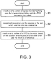
- FIG. 3 shows an operation flow of a component insertion method of one embodiment performed by the component insertion device 1 described above.
- a processing of automatically inserting the end portion 90e of the FPC 90 into the slot 602s of the FPC connector 602 is described with reference to FIG. 4A-FIG. 4E (viewed from the +x direction in FIG. 1A ) together.
- the in-process product 600 containing the FPC connector 602 is placed on the assembly table 800 in advance.
- the pair of the claws 102A, 102B of the gripper 101 of the robot 100 grips the central portion 90c of the FPC 90 in the state that the end portion 90e protrudes outward.
- the plate member 99 is mounted on the location 101s which is on the side surface of the gripper 101 and away from the gripped FPC 90 and protrudes outward.
- the end portion 99e of the plate member 99 and the end portion 90e of the FPC 90 face the same direction (-y direction which uses the robot 100 as a reference) in a mutually parallel manner.
- step S1 in FIG. 3 the robot control portion 30 of the controller 10 operates as a first insertion processing portion, and performs the processing in which the end portion 99e of the plate member 99 serving as the dummy component is inserted into the slot 602s of the FPC connector 602 by the robot 100 through compliance control which is based on the output of the force sensor 103.
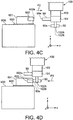
- the insertion processing (step S1 in FIG. 3 ) is performed through compliance control, since the plate member 99 exhibits rigidity, the insertion processing can be completed in a relatively short time (for example, about 15 seconds). Accordingly, as shown in FIG. 4B by an arrow P1, the end portion 99e of the plate member 99 is inserted into the slot 602s of the FPC connector 602.
- the processing of inserting through the compliance control starts from the state of FIG. 5A and is performed in the following sequence.
- the robot control portion 30 operates as a recognition processing portion and performs a processing of recognizing the position and the posture (x, y, z, yaw, pitch, roll) of the slot 602s which use the robot 100 as a reference.
- the recognition processing takes hardly any time (for example, less than one second).
- the recognized position and posture of the slot 602s which use the robot 100 as a reference are stored in the storage portion 12. After that, as shown in FIG. 4C by an arrow P2, the robot 100 is temporarily retracted in a direction (+y direction) away from the assembly table 800. Accordingly, the end portion 99e of the plate member 99 is drawn out from the slot 602s of the FPC connector 602.
- the robot control portion 30 operates as a second insertion processing portion and performs the processing in which the end portion 90e of the FPC 90 gripped in the gripper 101 is inserted, as shown in FIG. 4D by an arrow P3, into the slot 602s of the FPC connector 602 by the robot 100 through position control based on the position and the posture (x, y, z, yaw, pitch, roll) of the slot 602s which use the robot 100 as a reference.
- the insertion processing (step S3 in FIG. 3 ) can be completed in a relatively short time (for example, about five seconds) and is performed at a high accuracy. Therefore, the end portion 90e of the FPC 90 may also be more flexible than the plate member 99 as in this example. Therefore, according to the component insertion device 1, the relatively flexible end portion 90e of the FPC 90 can be automatically inserted into the FPC connector 602 having the slot 602s at a short time of about 20 seconds in total.
- the end portion 99e of the plate member 99 and the end portion 90e of the FPC 90 protrude toward the same direction from the gripper 101 in a mutually parallel manner. Therefore, during the insertion processing (step S3 in FIG. 3 ), the gripper 101 may move in parallel without the necessity of substantially changing the posture.
- this insertion processing (step S3 in FIG. 3 ) is performed in a sequence corresponding to FIG. 5A ⁇ FIG. 5B ⁇ FIG. 5D ⁇ FIG. 5F in FIG. 5 . That is, the searching operation in FIG. 5C and the pushing elimination operation in FIG. 5E are omitted.
- the location 101s which is in the gripper 101 and where the plate member 99 is mounted is set so as to be separated from the FPC connector 602 and the surrounding circuit board 601 and the like during the processing of inserting the end portion 90e of the FPC 90 into the slot 602s of the FPC connector 602 (step S3 in FIG. 3 ). Therefore, during the processing of inserting the end portion 90e of the FPC 90, the plate member 99 does not interfere with the FPC connector 602 and the surrounding circuit board 601 and the like, and the end portion 90e of the FPC 90 can be inserted smoothly.
- the pair of claws 102A, 102B of the gripper 101 of the robot 100 opens and releases the FPC 90. Then, as shown in FIG. 4E by an arrow P4, the robot 100 is retracted in a direction (+y direction) away from the assembly table 800.
- the claws 102A, 102B of the gripper 101 may grip the FPC 90 in a state of deviating from the position where the FPC 90 should be gripped (the original position where the FPC 90 should be gripped, the central portion 90c in the above example) or the posture (the posture that the end portion 99e faces the -y direction in the above example) which is the reference for gripping.
- a camera 20 is arranged as an imaging device and the gripping position or posture of the FPC 90 is taken by the camera 20.
- FIG. 7A for example, a camera 20 is arranged as an imaging device and the gripping position or posture of the FPC 90 is taken by the camera 20.
- the camera 20 is held above the FPC connector 602 by a stand 801 in a posture that the view field faces the robot 100 as shown by an arrow U1.
- the robot control portion 30 moves the FPC 90 by the robot 100 for a plurality of times in front of the camera 20 and takes a plurality of images by the camera 20 from mutually different angles.
- the robot control portion 30 gets the deviation of the gripping position or posture of the FPC 90 (deviation from the reference position or posture, the same applies hereinafter) based on the plurality of images, and corrects the deviation of the gripping position or posture of the FPC 90 on data.
- the robot control portion 30 operates as the second insertion processing portion and performs the processing in which the end portion 90e of the FPC 90 gripped in the gripper 101 is inserted into the slot 602s of the FPC connector 602 through position control (step S3 in FIG. 3 ).
- the end portion 90e of the FPC 90 can be smoothly inserted into the slot 602s of the FPC connector 602. Besides, similarly, even when there is individual difference such as dimension variation and the like in the FPC 90, the end portion 90e of the FPC 90 can be smoothly inserted into the slot 602s of the FPC connector 602.
- stereo cameras 20A, 20B are used as imaging devices to image the FPC 90 simultaneously from mutually different angles as shown by arrows U2 and U3, and the deviation of the gripping position or posture of the FPC 90 and /or the individual difference such as the dimension variation and the like of the FPC 90 are/is gotten based on the images. Accordingly, imaging times can be reduced and the processing time can be shortened.
- the stereo cameras 20A, 20B are illustrated in an up-and-down arrangement, and it is evident that the stereo cameras 20A, 20B may also be arranged left and right.
- the end portion 90e of the FPC 90 which has a plate-like shape and serves as the workpiece component is inserted into the FPC connector 602 which serves as the receiving portion having the slender straight-shaped slot 602s.
- the disclosure is not limited hereto.
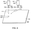
- the present disclosure is also applied to the case in which, as shown in FIG. 6 for example, lead pins 190e, 190f of an electrolytic capacitor 190 which serves as the workpiece component is inserted into a circuit board 700 (mounted on the assembly table 800, or may be fixed on the assembly table 800) which serves as the receiving portion having a pair of circular small holes 700e, 700f.
- the electrolytic capacitor 190 has a cylindrical main portion 190a, and a pair of lead pins 190e, 190f serving as the specific part that protrudes in a slender shape from an end surface 190b of the main portion 190a.
- the lead pins 190e, 190f have circular cross sections which fit the small holes 700e, 700f respectively, and a distance between centers of the lead pins 190e, 190f corresponds with the distance between centers of the small holes 700e, 700f.
- the material of the lead pins 190e, 190f is the material obtained by plating tin and copper on a copper core and is relatively flexible.
- a dummy component 199 that has entirely the same shape as that of the electrolytic capacitor 190 is prepared.
- the dummy component 199 has a cylindrical main portion 199a, and a pair of dummy pins 199e, 199f serving as the corresponding part that protrudes in a slender shape from an end surface 199b of the main portion 199a.
- the dummy pins 199e, 199f consist of, for example, stainless steel that exhibits rigidity.
- the robot control portion 30 of the controller 10 operates as the first insertion processing portion and performs the processing in which, as shown in FIG.
- the robot control portion 30 operates as the recognition processing portion and performs the processing of recognizing the position and the posture (x, y, z, yaw, pitch, roll) of the small holes 700e, 700f which use the robot 100 as the reference.
- step S3 in FIG. 3 the robot control portion 30 operates as the second insertion processing portion and performs the processing in which, as shown in FIG.
- the lead pins 190e, 190f of the electrolytic capacitor 190 are inserted into the small holes 700e, 700f of the circuit board 700 by the robot 100 through the position control.
- the pair of the lead pins 190e, 190f of the electrolytic capacitor 190 can be automatically inserted into the pair of small holes 700e, 700f of the circuit board 700 in a short time.
- the lead pins 190e, 190f of the electrolytic capacitor 190 can be sequentially inserted into each pair of small holes 700e, 700f by the same sequence as mentioned above (or may be inserted concurrently by a plurality of robots). Accordingly, a plurality of electrolytic capacitors 190 can be automatically mounted on the circuit board 700.
- the receiving portion having a slot or a hole (the FPC connector 602 contained in the in-process product 600, the circuit board 700) is placed on the assembly table 800, but the disclosure is not limited hereto.
- the receiving portion having a slot or a hole may be conveyed to the movable range of the robot 100 by, for example, a belt conveyor to maintain the arrangement relative to the robot 100 between the aforementioned processing (steps S1-S3 in FIG. 3 ).
- the combination of the receiving portion which has a slot or a hole of a certain shape and the workpiece component which has a shape fitting the slot or the hole is not limited to the aforementioned two examples of combination and there may be various combinations.
- the robot control portion 30 of the controller 10 is formed by a processor that operates in accordance with a program.
- the storage portion 12 is formed by a storage device such as a nonvolatile semiconductor memory and the like. That is, the robot control portion 30 and the storage portion 12 may be substantially formed by a computer device (for example, a programmable logic controller (PLC) and the like). Therefore, the component insertion method described by FIG. 3 is desirably formed as programs for the computer to execute.
- the programs are desirably stored in a computer readable non-transitory storage device. In that case, the aforementioned component insertion method can be implemented by making the computer device read and execute the programs stored in the storage device.
Landscapes
- Engineering & Computer Science (AREA)
- Robotics (AREA)
- Mechanical Engineering (AREA)
- Microelectronics & Electronic Packaging (AREA)
- Manufacturing & Machinery (AREA)
- Human Computer Interaction (AREA)
- Manipulator (AREA)
- Supply And Installment Of Electrical Components (AREA)
- Automatic Assembly (AREA)
Abstract
Description
- The present disclosure relates to a component insertion device and a component insertion method, in particular, to a component insertion device and a component insertion method by which a receiving portion having a slot or hole of a certain shape is inserted with a workpiece component that has a shape fitting the slot or the hole. Besides, the present disclosure relates to a program for making a computer execute the component insertion method.
- A typical case in which a receiving portion having a slot or hole of a certain shape is inserted with a workpiece component that has a shape fitting the slot or the hole may be, for example, the case in which, as disclosed in patent literature 1 (Japanese Laid-Open No.
10-27659 - Conventionally, attempts are made to use, for example, a robot to automatically perform this process (FPC insertion process) of sliding and inserting the FPC into the FPC connector.
- [Patent literature 1] Japanese Laid-Open No.
10-27659 - However, the fact is that the FPC insertion process is not mechanized or automatized because of the following reasons.
- The first reason to be listed is the difficulty in contact search. Specifically, although it is intended to arrange a force sensor on the robot to make the FPC contact the surrounding (vicinity of the opening) of the slot of the FPC connector and search the position of the slot based on a contact reaction force received by the FPC, the FPC itself may curve due to the contact manner and great plastic deformation occurs. Therefore, it is difficult to search the position of the slot based on the contact reaction force. Moreover, when great plastic deformation occurs in the FPC, the necessity of disposing the FPC arises.
- The second reason to be listed is the long duration of a takt time. Specifically, in order to avoid FPC damage (including plastic deformation), it is necessary to push the FPC slowly through compliance control. At this time, the setting of decelerating the pushing speed and decelerating an engagement elimination operation (the operation in which the FPC is slightly vibrated to eliminate the phenomenon that the FPC is caught at an entrance of the slot) is required. As a result, it takes, for example, about 150 seconds to insert one piece of FPC.
- Therefore, the present disclosure provides a component insertion device and a component insertion method by which a receiving portion having a slot or a hole of a certain shape can be automatically inserted with a workpiece component which is relatively flexible and has a shape fitting the slot or the hole in a short time. Besides, the present disclosure provides a program for making a computer execute this component insertion method.
- The component insertion device of the disclosure is
a component insertion device by which a receiving portion having a slot or a hole of a certain shape is inserted with a specific part of a workpiece component that has a shape fitting the slot or the hole, the component insertion device comprising: - a robot; and
- a control portion that controls the operation of the robot; wherein
- the robot comprises:
- a gripper capable of gripping the workpiece component in a state that the specific part protrudes outward;
- a dummy component that is mounted protruding outward on a location in the gripper and away from the gripped workpiece component, has a corresponding part with the same shape as the shape of the specific part of the workpiece component and exhibits rigidity; and
- a force sensor capable of detecting, through the gripper, a contact reaction force received by the dummy component from the surrounding of the slot or the hole of the receiving portion; and
- the control portion comprises:
- a first insertion processing portion that performs, in a state that the receiving portion is arranged in a movable range of the robot, a processing in which the corresponding part of the dummy component is inserted into the slot or the hole of the receiving portion by the robot through compliance control which is based on output of the force sensor;
- a recognition processing portion that performs, in a state that the corresponding part of the dummy component is inserted into the slot or the hole of the receiving portion, a processing in which a position and a posture of the slot or the hole which use the robot as a reference are recognized; and
- a second insertion processing portion that performs, in a state of maintaining the arrangement of the receiving portion, a processing in which the outwardly protruding specific part of the workpiece component gripped in the gripper is inserted into the slot or the hole of the receiving portion based on the position and the posture of the slot or the hole which use the robot as a reference by the robot through position control.
- In the specification, the "specific part" of the workpiece component corresponds to the part inserted into the slot or the hole. Therefore, it is sufficient that the "specific part" has a shape fitting the slot or the hole. The "specific part" is not limited to an end portion and may refer to other portions.
- Besides, the "rigidity" exhibited by the dummy component does not means complete rigidity and may be substantial rigidity that enables compliance control which is based on the output of the force sensor.
- Besides, in fact, the specific part of the workpiece component is a target which is more flexible than the dummy component. The reason is that if the specific part of the workpiece component has the same rigidity as the dummy component, there is no necessity to perform the processing of using the dummy component to recognize the position of the slot or the hole in advance, and the specific part of the workpiece component may be directly inserted into the slot or the hole of the receiving portion through compliance control.
- In the component insertion device of the disclosure, the gripper of the robot grips the workpiece component in the state that the specific part protrudes outward (outside the gripper). Besides, the dummy component is mounted on the location in the gripper and away from the gripped workpiece component and protrudes outward (outside the gripper). The first insertion processing portion of the control portion performs, in the state that the receiving portion is arranged in the movable range of the robot, the processing in which the corresponding part of the dummy component is inserted into the slot or the hole of the receiving portion by the robot through the compliance control which is based on the output of the force sensor. Although the insertion processing is performed through the compliance control, since the dummy component exhibits rigidity, the insertion processing can be completed in a relatively short time (for example, about 15 seconds). Next, in the state that the corresponding part of the dummy component is inserted into the slot or the hole of the receiving portion, the recognition processing portion performs the processing in which the position and the posture of the slot or the hole which use the robot as the reference are recognized. The recognition processing takes hardly any time (for example, less than one second). Next, the second insertion processing portion performs, in the state of maintaining the arrangement of the receiving portion (at least after the recognition processing), the processing in which the specific part of the workpiece component gripped in the gripper is inserted into the slot or the hole of the receiving portion by the robot through position control based on the position and the posture of the slot or the hole which use the robot as the reference. Because the accurate position and posture of the slot or the hole which use the robot as the reference is already recognized, the insertion processing can be completed in a relatively short time (for example, about five seconds) and is performed at a high accuracy. Therefore, the specific part of the workpiece component may be more flexible than the dummy component. Therefore, according to the component insertion device, the receiving portion having a slot or a hole of a certain shape can be automatically inserted with the relatively flexible workpiece component that has a shape fitting the slot or the hole in a short time.
- In the component insertion device of one embodiment, the location in the gripper where the dummy component is mounted is set in a manner that the dummy component is separated from the receiving portion and/or members around the receiving portion during the processing of inserting the specific part of the workpiece component into the slot or the hole of the receiving portion.
- In the component insertion device of this embodiment, during the processing of inserting the specific part of the workpiece component into the slot or the hole of the receiving portion, the dummy component can be smoothly inserted without interfering with the receiving portion and/or the members around the receiving portion.
- In the component insertion device of one embodiment, the specific part of the workpiece component gripped by the gripper and the corresponding part of the dummy component mounted on the gripper protrude toward the same direction in a mutually parallel manner.
- In the component insertion device of this embodiment, during the processing of inserting the specific part of the workpiece component into the slot or the hole of the receiving portion, the gripper may move in parallel without the necessity of substantially changing the posture.
- The component insertion method of the disclosure is
a component insertion method in which a receiving portion having a slot or a hole of a certain shape is inserted with a specific part of a workpiece component that has a shape fitting the slot or the hole by the aforementioned component insertion device, wherein
in a state that the receiving portion is arranged in a movable range of the robot, the gripper of the robot grips the workpiece component in the state that the specific part protrudes outward, and the dummy component is mounted on the location in the gripper and away from the gripped workpiece component and protrudes outward,
a processing is performed in which the corresponding part of the dummy component is inserted into the slot or the hole of the receiving portion by the robot through compliance control which is based on the output of the force sensor,
in a state that the corresponding part of the dummy component is inserted into the slot or the hole of the receiving portion, a processing is performed in which the position and the posture of the slot or the hole which use the robot as a reference are recognized, and after that,
in a state of maintaining the arrangement of the receiving portion, a processing is performed in which the outwardly protruding specific part of the workpiece component gripped in the gripper is inserted into the slot or the hole of the receiving portion by the robot through position control based on the position and the posture of the slot or the hole which use the robot as the reference. - According to the component insertion method of the disclosure, the receiving portion having the slot or the hole of a certain shape can be automatically inserted with the relatively flexible workpiece component that has a shape fitting the slot or the hole in a short time.
- The program of the disclosure is a program for making a computer execute the component insertion method.
- By making the computer execute the program of the disclosure, the aforementioned component insertion method can be implemented.
- As seen from the above, according to the component insertion device and the component insertion method of the disclosure, the receiving portion having the slot or the hole of a certain shape can be automatically inserted with the relatively flexible workpiece component that has a shape fitting the slot or the hole in a short time. Besides, by making the computer execute the program of the disclosure, the component insertion method can be implemented.
-
-
FIG. 1A is a perspective view schematically showing an external appearance of a component insertion device of one embodiment of the present disclosure.FIG. 1B is a diagram showing the vicinity of a gripper of a robot constituting the component insertion device when viewed laterally.FIG. 1C is a diagram showing a FPC connector that has a slender straight-shaped slot and a FPC that has a plate-like shape fitting the slot. -
FIG. 2 is a diagram showing a block constitution of a control system of the component insertion device. -
FIG. 3 is a diagram showing a flow of a processing in which an end portion of the FPC is automatically inserted into the slot of the FPC connector by the component insertion device. -
FIG. 4A is a diagram schematically showing a process of automatically inserting the end portion of the FPC into the slot of the FPC connector. -
FIG. 4B is a diagram schematically showing a process of automatically inserting the end portion of the FPC into the slot of the FPC connector. -
FIG. 4C is a diagram schematically showing a process of automatically inserting the end portion of the FPC into the slot of the FPC connector. -
FIG. 4D is a diagram schematically showing a process of automatically inserting the end portion of the FPC into the slot of the FPC connector. -
FIG. 4E is a diagram schematically showing a process of automatically inserting the end portion of the FPC into the slot of the FPC connector. -
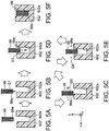
FIG. 5A-FIG. 5F are diagrams showing the sequence of inserting an end portion of a dummy component into the slot of the FPC connector through compliance control which is based on output of a force sensor. -
FIG. 6 is a diagram showing an example in which lead pins of electrolytic capacitors are inserted into small holes of a circuit board. -
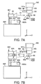
FIG. 7A is a diagram describing an example in which a camera serving as an imaging device is arranged and a gripping position or posture of the FPC is gotten based on images taken by the camera.FIG. 7B is a diagram describing an example in which a stereo camera is arranged and the gripping position or posture of the FPC is gotten based on images taken by the stereo camera. - Embodiments of the present disclosure are described below in detail with reference to the diagrams.
-
FIG. 1A schematically shows an external appearance of acomponent insertion device 1 of one embodiment of the present disclosure. In this example, thecomponent insertion device 1 includes arobot 100 that is arranged near an assembly table 800 and acontroller 10 that controls the movement of therobot 100. - In this example, the assembly table 800 is arranged in a movable range of the
robot 100. An in-process product 600, on which acircuit board 601 which has a FPC (Flexible Printed Circuit; flexible wiring board)connector 602 serving as a receiving portion is mounted, is placed on the assembly table 800 (the in-process product 600 may be fixed on the assembly table 800 by an unillustrated element). As shown inFIG. 1C , theFPC connector 602 has a slender straight-shapedslot 602s. Thecomponent insertion device 1 is a device used to automatically insert anend portion 90e serving as a specific part of a rectangular plate-like FPC 90 serving as a workpiece component into theslot 602s of theFPC connector 602. A longitudinal dimension SL1 and a lateral dimension SL2 of an opening of theslot 602s are respectively larger than a longitudinal dimension FP1 (3 cm in this example) and a lateral dimension FP2 (0.20 mm in this example) of theend portion 90e of theFPC 90 by a fixed clearance dimension, and are set to SL1=3.2 cm and SL2=2 mm in this example. A depth of theslot 602s (that is, an insertion depth of the FPC 90) is set to 5 mm in this example. Moreover, the lateral dimension SL2 of theslot 602s may gradually become smaller (narrower) as the depth in theslot 602s increases. - In this example, the
robot 100 is made of a 6-axis (6 control axes) articulated robot having agripper 101. Therobot 100 has three axes which show a translation freedom degree, namely x (position in x axis), y (position in y axis) and z (position in z axis), and three axes which show a rotation freedom degree, namely yaw (yaw angle), pitch (pitch angle) and roll (roll angle).FIG. 1B shows the vicinity (a part surrounded by a two-dot chain line B) of thegripper 101 inFIG. 1A . As shown inFIG. 1B , in this example, thegripper 101 has a pair ofclaws FPC 90. The pair ofclaws front end surface 101b of thegripper 101. Moreover, inFIG. 1B , theclaw 102B is hidden and arranged behind theclaw 102A. When theclaws gripper 101 grip theFPC 90 in acentral portion 90c of theFPC 90, a state in which theend portion 90e of theFPC 90 protrudes outward is reached. - In this example, as for dimensions of the rectangular plate-
like FPC 90, a total length is set to 7 cm, a width is set to 3 cm(=FP1) and a thickness is set to 0.20 mm(=FP2). In a state that thecentral portion 90c of theFPC 90 is gripped by theclaws gripper 101, a state in which theend portion 90e of theFPC 90 protrudes toward the outside (the lateral side in this example) of theclaws gripper 101 by about 3 cm is reached. - The
FPC 90 is a publicly known FPC and is formed by arranging a conductive foil (such as a copper foil) on a relatively flexible substrate like polyimide and so on via an adhesion layer (for example, an epoxy thermosetting adhesive). - At a
location 101s which is on a side surface of thegripper 101 and away from the grippedFPC 90, aplate member 99 serving as a dummy component which has a rectangular plate-like shape and exhibits rigidity is mounted and protrudes outward (outside the gripper 101). The shape of anend portion 99e of theplate member 99 serving as a corresponding part is set to be the same as the shape of theend portion 90e of theFPC 90. Thelocation 101s which is on the side surface of thegripper 101 and where theplate member 99 is mounted is set in a manner that theplate member 99 does not interfere with theFPC connector 602 and thecircuit board 601 and the like around the FPC connector 602 (away from these members) during the processing (step S3 inFIG. 3 ) described later. Besides, theend portion 99e of theplate member 99 and theend portion 90e of theFPC 90 protrude toward the same direction from thegripper 101 in a mutually parallel manner (that is, the relative angle is zero). - In this example, as for the dimensions of the rectangular plate-
like plate member 99, a protruding dimension from the side surface of thegripper 101 is set to about 3 cm-6 cm, the width is set to 3 cm and the thickness is set to 0.20 mm. - The "rigidity" exhibited by the
plate member 99 does not means complete rigidity and may be substantial rigidity that enables compliance control which is based on the output of aforce sensor 103 described later. Therefore, in addition to metal materials such as stainless steel, iron and the like, relatively hard plastic materials such as polycarbonate (PC) and the like can be used as the material of theplate member 99. - Besides, the
force sensor 103 is mounted at a location near thegripper 101 of therobot 100. Theforce sensor 103 can detect, from the surrounding of theslot 602s of theFPC connector 602, a contact reaction force received by theplate member 99 via thegripper 101 during the processing (step S1 inFIG. 3 ) described later. - As shown in
FIG. 2 , in this example, thecontroller 10 includes aninput portion 11, astorage portion 12, and arobot control portion 30. - In this example, the
input portion 11 consists of a teaching pendant. In this example, theinput portion 11 is used especially for a user to input a processing start command. - In this example, the
storage portion 12 consists of a nonvolatile semiconductor memory. In this example, thestorage portion 12 stores the position and the posture of theslot 602s which use therobot 100 as a reference especially during the processing (step S2 inFIG. 3 ) described later. - In this example, the
robot control portion 30 is formed by a processor that operates according to a robot control program stored in thestorage portion 12. Therobot control portion 30 controls the 6-axis robot 100 using control information CV consisting of six elements which have the same number as the axis number of the 6-axis robot 100. The control information CV includes three elements which show the translation freedom degree, namely x (position of x axis), y (position of y axis) and z (position of z axis), and three elements which show the rotation freedom degree, namely yaw (value of yaw angle), pitch (value of pitch angle) and roll (value of roll angle). In a common position control, the value of each element of the control information CV is sequentially updated at a fixed cycle, and each axis of therobot 100 is driven accordingly. - Besides, in this example, the
robot control portion 30 can receive an output signal FS of theforce sensor 103 and perform compliance control (control which uses the position and the posture of the front end of the robot and the force applied to the front end of the robot to make the robot move gently) on therobot 100. In the compliance control, for example, the movement of therobot 100 is feedback controlled in a manner that the force component in a direction (x direction and z direction) that intersects (orthogonal to) the insertion direction (for example, -y direction) detected in theforce sensor 103 decreases. - The transmission and reception of the control information CV and the output signal FS of the
force sensor 103 between thecontroller 10 and therobot 100 is performed via acable 10C shown inFIG. 1A . -
FIG. 3 shows an operation flow of a component insertion method of one embodiment performed by thecomponent insertion device 1 described above. Next, a processing of automatically inserting theend portion 90e of theFPC 90 into theslot 602s of theFPC connector 602 is described with reference toFIG. 4A-FIG. 4E (viewed from the +x direction inFIG. 1A ) together. - As shown in
FIG. 4A , the in-process product 600 containing theFPC connector 602 is placed on the assembly table 800 in advance. Besides, the pair of theclaws gripper 101 of therobot 100 grips thecentral portion 90c of theFPC 90 in the state that theend portion 90e protrudes outward. Besides, theplate member 99 is mounted on thelocation 101s which is on the side surface of thegripper 101 and away from the grippedFPC 90 and protrudes outward. In the state ofFIG. 4A , theend portion 99e of theplate member 99 and theend portion 90e of theFPC 90 face the same direction (-y direction which uses therobot 100 as a reference) in a mutually parallel manner. - When the user inputs the processing start command by the
input portion 11, first, as shown in step S1 inFIG. 3 , therobot control portion 30 of thecontroller 10 operates as a first insertion processing portion, and performs the processing in which theend portion 99e of theplate member 99 serving as the dummy component is inserted into theslot 602s of theFPC connector 602 by therobot 100 through compliance control which is based on the output of theforce sensor 103. Although the insertion processing (step S1 inFIG. 3 ) is performed through compliance control, since theplate member 99 exhibits rigidity, the insertion processing can be completed in a relatively short time (for example, about 15 seconds). Accordingly, as shown inFIG. 4B by an arrow P1, theend portion 99e of theplate member 99 is inserted into theslot 602s of theFPC connector 602. - Here, the processing of inserting through the compliance control starts from the state of
FIG. 5A and is performed in the following sequence. First, as shown inFIG. 5B by an arrow Q1, theend portion 99e of theplate member 99 is butted against the surrounding of theslot 602s of the FPC connector 602 (near the opening) (butting operation). Next, as shown inFIG. 5C by an arrow Q2, the position of the opening of theslot 602s is searched by theend portion 99e of the plate member 99 (searching operation). Once the position of the opening of theslot 602s is found, as shown inFIG. 5D by an arrow Q3, theend portion 99e of theplate member 99 is pushed into the vicinity of the entrance of theslot 602s of the FPC connector 602 (pushing operation). During the pushing, as shown inFIG. 5E by a mark Q4, theend portion 99e of theplate member 99 is slightly vibrated to eliminate the engagement (a phenomenon of being caught at the entrance of theslot 602s) (engagement elimination operation). In this way, as shown inFIG. 5F , theend portion 99e of theplate member 99 is inserted into theslot 602s of theFPC connector 602. - Next, in the state that the
end portion 99e of theplate member 99 is inserted into theslot 602s of theFPC connector 602, as shown in step S2 inFIG. 3 , therobot control portion 30 operates as a recognition processing portion and performs a processing of recognizing the position and the posture (x, y, z, yaw, pitch, roll) of theslot 602s which use therobot 100 as a reference. The recognition processing (step S2 inFIG. 3 ) takes hardly any time (for example, less than one second). The recognized position and posture of theslot 602s which use therobot 100 as a reference are stored in thestorage portion 12. After that, as shown inFIG. 4C by an arrow P2, therobot 100 is temporarily retracted in a direction (+y direction) away from the assembly table 800. Accordingly, theend portion 99e of theplate member 99 is drawn out from theslot 602s of theFPC connector 602. - Next, in this example, in the state of maintaining the arrangement of the
FPC connector 602 after step S1 inFIG. 3 , as shown in step S3 inFIG. 3 , therobot control portion 30 operates as a second insertion processing portion and performs the processing in which theend portion 90e of theFPC 90 gripped in thegripper 101 is inserted, as shown inFIG. 4D by an arrow P3, into theslot 602s of theFPC connector 602 by therobot 100 through position control based on the position and the posture (x, y, z, yaw, pitch, roll) of theslot 602s which use therobot 100 as a reference. - Since the accurate position and posture (x, y, z, yaw, pitch, roll) of the
slot 602s which use therobot 100 as a reference are already recognized, the insertion processing (step S3 inFIG. 3 ) can be completed in a relatively short time (for example, about five seconds) and is performed at a high accuracy. Therefore, theend portion 90e of theFPC 90 may also be more flexible than theplate member 99 as in this example. Therefore, according to thecomponent insertion device 1, the relativelyflexible end portion 90e of theFPC 90 can be automatically inserted into theFPC connector 602 having theslot 602s at a short time of about 20 seconds in total. - In particular, the
end portion 99e of theplate member 99 and theend portion 90e of theFPC 90 protrude toward the same direction from thegripper 101 in a mutually parallel manner. Therefore, during the insertion processing (step S3 inFIG. 3 ), thegripper 101 may move in parallel without the necessity of substantially changing the posture. - Specifically, this insertion processing (step S3 in
FIG. 3 ) is performed in a sequence corresponding toFIG. 5A →FIG. 5B →FIG. 5D →FIG. 5F inFIG. 5 . That is, the searching operation inFIG. 5C and the pushing elimination operation inFIG. 5E are omitted. - The
location 101s which is in thegripper 101 and where theplate member 99 is mounted is set so as to be separated from theFPC connector 602 and the surroundingcircuit board 601 and the like during the processing of inserting theend portion 90e of theFPC 90 into theslot 602s of the FPC connector 602 (step S3 inFIG. 3 ). Therefore, during the processing of inserting theend portion 90e of theFPC 90, theplate member 99 does not interfere with theFPC connector 602 and the surroundingcircuit board 601 and the like, and theend portion 90e of theFPC 90 can be inserted smoothly. - After that, the pair of
claws gripper 101 of therobot 100 opens and releases theFPC 90. Then, as shown inFIG. 4E by an arrow P4, therobot 100 is retracted in a direction (+y direction) away from the assembly table 800. - When the
robot 100 uses thegripper 101 to grip theFPC 90 which is a workpiece component, theclaws gripper 101 may grip theFPC 90 in a state of deviating from the position where theFPC 90 should be gripped (the original position where theFPC 90 should be gripped, thecentral portion 90c in the above example) or the posture (the posture that theend portion 99e faces the -y direction in the above example) which is the reference for gripping. In order to successfully insert theFPC 90 even in this case, it is desirable that, as shown inFIG. 7A for example, acamera 20 is arranged as an imaging device and the gripping position or posture of theFPC 90 is taken by thecamera 20. In the example ofFIG. 7A , thecamera 20 is held above theFPC connector 602 by astand 801 in a posture that the view field faces therobot 100 as shown by an arrow U1. In this case, before the processing (step S3 inFIG. 3 ) in which theend portion 90e of theFPC 90 is inserted into theslot 602s in the state that theclaws gripper 101 grip the FPC 90 (or even before the processing of inserting theend portion 99e of the plate member 99 (step S1 inFIG. 3 )), therobot control portion 30 moves theFPC 90 by therobot 100 for a plurality of times in front of thecamera 20 and takes a plurality of images by thecamera 20 from mutually different angles. Then, therobot control portion 30 gets the deviation of the gripping position or posture of the FPC 90 (deviation from the reference position or posture, the same applies hereinafter) based on the plurality of images, and corrects the deviation of the gripping position or posture of theFPC 90 on data. In addition, therobot control portion 30 operates as the second insertion processing portion and performs the processing in which theend portion 90e of theFPC 90 gripped in thegripper 101 is inserted into theslot 602s of theFPC connector 602 through position control (step S3 inFIG. 3 ). In this case, even when theFPC 90 is gripped in the state of deviating from the reference position or posture, theend portion 90e of theFPC 90 can be smoothly inserted into theslot 602s of theFPC connector 602. Besides, similarly, even when there is individual difference such as dimension variation and the like in theFPC 90, theend portion 90e of theFPC 90 can be smoothly inserted into theslot 602s of theFPC connector 602. - Moreover, as shown in
FIG. 7B , it may be that stereo cameras (spatially separated cameras) 20A, 20B are used as imaging devices to image theFPC 90 simultaneously from mutually different angles as shown by arrows U2 and U3, and the deviation of the gripping position or posture of theFPC 90 and /or the individual difference such as the dimension variation and the like of theFPC 90 are/is gotten based on the images. Accordingly, imaging times can be reduced and the processing time can be shortened. Besides, moreover, inFIG. 7B , thestereo cameras 20A, 20B are illustrated in an up-and-down arrangement, and it is evident that thestereo cameras 20A, 20B may also be arranged left and right. - In the above example, the case is described in which the
end portion 90e of theFPC 90 which has a plate-like shape and serves as the workpiece component is inserted into theFPC connector 602 which serves as the receiving portion having the slender straight-shapedslot 602s. However, the disclosure is not limited hereto. The present disclosure is also applied to the case in which, as shown inFIG. 6 for example, leadpins electrolytic capacitor 190 which serves as the workpiece component is inserted into a circuit board 700 (mounted on the assembly table 800, or may be fixed on the assembly table 800) which serves as the receiving portion having a pair of circularsmall holes electrolytic capacitor 190 has a cylindricalmain portion 190a, and a pair oflead pins end surface 190b of themain portion 190a. Here, the lead pins 190e, 190f have circular cross sections which fit thesmall holes small holes dummy component 199 that has entirely the same shape as that of theelectrolytic capacitor 190 is prepared. Thedummy component 199 has a cylindricalmain portion 199a, and a pair ofdummy pins end surface 199b of themain portion 199a. The dummy pins 199e, 199f consist of, for example, stainless steel that exhibits rigidity. Besides, in step S1 inFIG. 3 , therobot control portion 30 of thecontroller 10 operates as the first insertion processing portion and performs the processing in which, as shown inFIG. 6 by an arrow P11, the dummy pins 199e, 199f of thedummy component 199 are inserted into thesmall holes circuit board 700 by therobot 100 through the compliance control which is based on the output of theforce sensor 103. Next, in step S2 inFIG. 3 , therobot control portion 30 operates as the recognition processing portion and performs the processing of recognizing the position and the posture (x, y, z, yaw, pitch, roll) of thesmall holes robot 100 as the reference. Next, in step S3 inFIG. 3 , therobot control portion 30 operates as the second insertion processing portion and performs the processing in which, as shown inFIG. 6 by an arrow P12, based on the position and the posture (x, y, z, yaw, pitch, roll) of thesmall holes robot 100 as the reference, the lead pins 190e, 190f of theelectrolytic capacitor 190 are inserted into thesmall holes circuit board 700 by therobot 100 through the position control. In this way, the pair of the lead pins 190e, 190f of theelectrolytic capacitor 190 can be automatically inserted into the pair ofsmall holes circuit board 700 in a short time. - Moreover, when plural pairs of
small holes circuit board 700 are arranged, the lead pins 190e, 190f of theelectrolytic capacitor 190 can be sequentially inserted into each pair ofsmall holes electrolytic capacitors 190 can be automatically mounted on thecircuit board 700. - In the example described above, the receiving portion having a slot or a hole (the
FPC connector 602 contained in the in-process product 600, the circuit board 700) is placed on the assembly table 800, but the disclosure is not limited hereto. The receiving portion having a slot or a hole may be conveyed to the movable range of therobot 100 by, for example, a belt conveyor to maintain the arrangement relative to therobot 100 between the aforementioned processing (steps S1-S3 inFIG. 3 ). - Besides, the combination of the receiving portion which has a slot or a hole of a certain shape and the workpiece component which has a shape fitting the slot or the hole is not limited to the aforementioned two examples of combination and there may be various combinations.
- The
robot control portion 30 of thecontroller 10 is formed by a processor that operates in accordance with a program. Besides, thestorage portion 12 is formed by a storage device such as a nonvolatile semiconductor memory and the like. That is, therobot control portion 30 and thestorage portion 12 may be substantially formed by a computer device (for example, a programmable logic controller (PLC) and the like). Therefore, the component insertion method described byFIG. 3 is desirably formed as programs for the computer to execute. Besides, the programs are desirably stored in a computer readable non-transitory storage device. In that case, the aforementioned component insertion method can be implemented by making the computer device read and execute the programs stored in the storage device. -
- 1
- component insertion device
- 10
- controller
- 90
- FPC
- 99
- plate member
- 100
- robot
- 101
- gripper
- 102A, 102B
- claw
- 103
- force sensor
- 190
- electrolytic capacitor
- 199
- dummy component
- 602
- FPC connector
- 602s
- slot
- 700
- circuit board
- 700e, 700f
- small holes
Claims (5)
- A component insertion device (1), characterized in that, by which a receiving portion (602, 700) having a slot (602s) or a hole (700e, 700f) is inserted with a specific part (90e, 190e, 190f) of a workpiece component (90, 190) that has a shape fitting the slot (602s) or the hole (700e, 700f), the component insertion device (1) comprising:a robot (100); anda control portion (10) that controls the operation of the robot (100); whereinthe robot (100) comprises:a gripper (101) capable of gripping the workpiece component (90, 190) in a state that the specific part (90e, 190e, 190f) protrudes outward;a dummy component (99, 199) that is mounted protruding outward on a location (101s) in the gripper (101) and away from the gripped workpiece component (90, 190), has a corresponding part (99e, 199e, 199f) with the same shape as the shape of the specific part (90e, 190e, 190f) of the workpiece component (90, 190) and exhibits rigidity; anda force sensor (103) capable of detecting, through the gripper (101), a contact reaction force received by the dummy component (99, 199) from the surrounding of the slot (602s) or the hole (700e, 700f) of the receiving portion (602, 700); andthe control portion (10) comprises:a first insertion processing portion (30) that performs, in a state that the receiving portion (602, 700) is arranged in a movable range of the robot (100), a processing in which the corresponding part (99e, 199e, 199f) of the dummy component (99, 199) is inserted into the slot (602s) or the hole (700e, 700f) of the receiving portion (602, 700) by the robot (100) through compliance control which is based on output of the force sensor (103);a recognition processing portion that performs, in a state that the corresponding part (99e, 199e, 199f) of the dummy component (99, 199) is inserted into the slot (602s) or the hole (700e, 700f) of the receiving portion (602, 700), a processing in which a position and a posture of the slot (602s) or the hole (700e, 700f) which use the robot (100) as a reference are recognized; anda second insertion processing portion (30) that performs, in a state of maintaining the arrangement of the receiving portion (602, 700), a processing in which the outwardly protruding specific part (90e, 190e, 190f) of the workpiece component (90, 190) gripped in the gripper (101) is inserted into the slot (602s) or the hole (700e, 700f) of the receiving portion (602, 700) based on the position and the posture of the slot (602s) or the hole (700e, 700f) which use the robot (100) as a reference by the robot (100) through position control.
- The component insertion device (1) according to claim 1, wherein
the location (101s) in the gripper (101) where the dummy component (99, 199) is mounted is set in a manner that the dummy component (99, 199) is separated from the receiving portion (602, 700) and/or members around the receiving portion (602, 700) during the processing of inserting the specific part (90e, 190e, 190f) of the workpiece component (90, 190) into the slot (602s) or the hole (700e, 700f) of the receiving portion (602, 700). - The component insertion device (1) according to claim 1 or 2, wherein
the specific part (90e, 190e, 190f) of the workpiece component (90, 190) gripped by the gripper (101) and the corresponding part (99e, 199e, 199f) of the dummy component (99, 199) mounted on the gripper (101) protrude from the gripper (101) toward the same direction in a mutually parallel manner. - A component insertion method, characterized in that, in which a receiving portion (602, 700) having a slot (602s) or a hole (700e, 700f) is inserted with a specific part (90e, 190e, 190f) of a workpiece component (90, 190) that has a shape fitting the slot (602s) or the hole (700e, 700f) by the component insertion device (1) according to claim 1, wherein
in a state that the receiving portion (602, 700) is arranged in a movable range of the robot (100), the gripper (101) of the robot (100) grips the workpiece component (90, 190) in the state that the specific part (90e, 190e, 190f) protrudes outward, and the dummy component (99, 199) is mounted on the location (101s) in the gripper (101) and away from the gripped workpiece component (90, 190) and protrudes outward,
a processing is performed in which the corresponding part (99e, 199e, 199f) of the dummy component (99, 199) is inserted into the slot (602s) or the hole (700e, 700f) of the receiving portion (602, 700) by the robot (100) through compliance control which is based on the output of the force sensor (103),
in a state that the corresponding part (99e, 199e, 199f) of the dummy component (99, 199) is inserted into the slot (602s) or the hole (700e, 700f) of the receiving portion (602, 700), a processing is performed in which the position and the posture of the slot (602s) or the hole (700e, 700f) which use the robot (100) as a reference are recognized, and after that
in a state of maintaining the arrangement of the receiving portion (602, 700), a processing is performed in which the outwardly protruding specific part (90e, 190e, 190f) of the workpiece component (90, 190) gripped in the gripper (101) is inserted into the slot (602s) or the hole (700e, 700f) of the receiving portion (602, 700) by the robot (100) through position control based on the position and the posture of the slot (602s) or the hole (700e, 700f) which use the robot (100) as the reference. - A program, characterized in that, being for making a computer execute the component insertion method according to claim 4.
Applications Claiming Priority (1)
| Application Number | Priority Date | Filing Date | Title |
|---|---|---|---|
| JP2018044533A JP2019160973A (en) | 2018-03-12 | 2018-03-12 | Component insertion device, component insertion method, and program |
Publications (2)
| Publication Number | Publication Date |
|---|---|
| EP3539733A1 true EP3539733A1 (en) | 2019-09-18 |
| EP3539733B1 EP3539733B1 (en) | 2021-02-17 |
Family
ID=65013572
Family Applications (1)
| Application Number | Title | Priority Date | Filing Date |
|---|---|---|---|
| EP19151168.2A Not-in-force EP3539733B1 (en) | 2018-03-12 | 2019-01-10 | Component insertion device, component insertion method and program |
Country Status (4)
| Country | Link |
|---|---|
| US (1) | US11171431B2 (en) |
| EP (1) | EP3539733B1 (en) |
| JP (1) | JP2019160973A (en) |
| CN (1) | CN110253564B (en) |
Families Citing this family (17)
| Publication number | Priority date | Publication date | Assignee | Title |
|---|---|---|---|---|
| JP7306937B2 (en) * | 2019-09-25 | 2023-07-11 | ファナック株式会社 | A control device for a robot device that adjusts the position of a member supported by a robot |
| US11701776B2 (en) | 2019-10-25 | 2023-07-18 | Dexterity, Inc. | Robotic kitting machine |
| US11606865B2 (en) | 2019-11-08 | 2023-03-14 | Raytheon Company | Method for forming channels in printed circuit boards by stacking slotted layers |
| US11653484B2 (en) * | 2019-11-08 | 2023-05-16 | Raytheon Company | Printed circuit board automated layup system |
| JP7413165B2 (en) * | 2020-06-29 | 2024-01-15 | 川崎重工業株式会社 | Electronic component mounting device and electronic component mounting method |
| JP2022023737A (en) * | 2020-07-27 | 2022-02-08 | トヨタ自動車株式会社 | Assembly method of rotor and control apparatus of rotor assembly device |
| US11850804B2 (en) * | 2020-07-28 | 2023-12-26 | Divergent Technologies, Inc. | Radiation-enabled retention features for fixtureless assembly of node-based structures |
| JP7580997B2 (en) * | 2020-09-28 | 2024-11-12 | 株式会社日立製作所 | Apparatus and method for inserting object |
| JP7802084B2 (en) | 2020-11-10 | 2026-01-19 | ブライト マシーンズ インコーポレイテッド | Method and system for improved automatic calibration of a robotic cell |
| MX2024000605A (en) | 2021-07-16 | 2024-03-15 | Bright Machines Inc | Method and apparatus for vision-based tool localization. |
| TW202317338A (en) * | 2021-10-21 | 2023-05-01 | 日商倉敷紡績股份有限公司 | Connection method for board to board connector |
| CN115609254B (en) * | 2022-09-29 | 2023-09-22 | 广州市斯睿特智能科技有限公司 | Automatic flexible circuit board assembly system, method and device |
| US20240237321A9 (en) * | 2022-10-24 | 2024-07-11 | Intel Corporation | Methods and apparatus for using robotics to assemble/de-assemble components and perform socket inspection in server board manufacturing |
| CN115922678B (en) * | 2022-12-01 | 2025-08-05 | 中国电子科技集团公司第十四研究所 | A flexible method for inserting robot modules |
| JP7856591B2 (en) * | 2023-02-06 | 2026-05-11 | 株式会社日立製作所 | Robot control method and system |
| US20240353816A1 (en) * | 2023-04-21 | 2024-10-24 | Bright Machines, Inc. | Vision-Based Programless Assembly |
| KR102982456B1 (en) | 2024-09-02 | 2026-06-25 | 주식회사 에이치피케이 | Method for soldering FPCB sensor-wires |
Citations (5)
| Publication number | Priority date | Publication date | Assignee | Title |
|---|---|---|---|---|
| JPH1027659A (en) | 1996-07-10 | 1998-01-27 | Sumitomo Wiring Syst Ltd | FPC connector |
| US20110153076A1 (en) * | 2009-12-22 | 2011-06-23 | Canon Kabushiki Kaisha | Robot system, and control apparatus and method thereof |
| US20140114477A1 (en) * | 2011-11-30 | 2014-04-24 | Panasonic Corporation | Teaching device for robot, robot apparatus, method of controlling teaching device for robot, and control program of teaching device for robot |
| US20160073514A1 (en) * | 2014-09-08 | 2016-03-10 | Panasonic Intellectual Property Management Co., Ltd. | Insertion head, component insertion device, and component mounting line |
| WO2016186009A1 (en) * | 2015-05-20 | 2016-11-24 | 川崎重工業株式会社 | Electrical equipment attachment device and method |
Family Cites Families (19)
| Publication number | Priority date | Publication date | Assignee | Title |
|---|---|---|---|---|
| JPS5947129A (en) * | 1982-09-06 | 1984-03-16 | Mitsubishi Electric Corp | Assembly device for shaft or the like |
| JPS63174102A (en) * | 1987-01-14 | 1988-07-18 | Matsushita Electric Ind Co Ltd | Assembly method using horizontal articulated direct drive robot |
| JPH04348885A (en) * | 1991-05-24 | 1992-12-03 | Nippon Telegr & Teleph Corp <Ntt> | Method for detecting fitting position in assembly of parts by use of robot |
| US7141213B1 (en) * | 1996-07-05 | 2006-11-28 | Beckman Coulter, Inc. | Automated sample processing system |
| JP2001326201A (en) * | 2000-05-16 | 2001-11-22 | Ebara Corp | Polishing equipment |
| US6822413B2 (en) * | 2002-03-20 | 2004-11-23 | Fsi International, Inc. | Systems and methods incorporating an end effector with a rotatable and/or pivotable body and/or an optical sensor having a light path that extends along a length of the end effector |
| KR20060015557A (en) * | 2003-04-28 | 2006-02-17 | 스티븐 제임스 크램톤 | Cmm arm with exoskeleton |
| JP4271249B2 (en) * | 2007-06-14 | 2009-06-03 | ファナック株式会社 | Mating device |
| JP2009211816A (en) * | 2008-02-29 | 2009-09-17 | Toshiba Corp | Printed circuit board, electronic equipment, and connector |
| US20130263433A1 (en) * | 2012-03-26 | 2013-10-10 | Newfrey Llc | Automated Fastener Setting Tool |
| EP2684653A1 (en) * | 2012-06-20 | 2014-01-15 | Kabushiki Kaisha Yaskawa Denki | Robot system and method for manufacturing fitting |
| CN105144553B (en) * | 2013-05-01 | 2017-11-28 | 日产自动车株式会社 | Magnet insertion method for inserting magnets into the rotor core |
| US9919421B2 (en) * | 2015-04-15 | 2018-03-20 | Abb Schweiz Ag | Method and apparatus for robot path teaching |
| CN105470184B (en) * | 2015-12-31 | 2018-08-10 | 北京北方华创微电子装备有限公司 | A kind of silicon chip transports method safely |
| JP2017196705A (en) * | 2016-04-28 | 2017-11-02 | セイコーエプソン株式会社 | Robot and robot system |
| CN106272416B (en) * | 2016-08-29 | 2020-12-29 | 上海交通大学 | Robotic slender axis precision assembly system and method based on force sense and vision |
| CN206292312U (en) * | 2016-09-22 | 2017-06-30 | 珠海市运泰利自动化设备有限公司 | Soft arranging wire contraposition adjustment test platform based on optical alignment |
| CN206717896U (en) * | 2017-04-27 | 2017-12-08 | 深圳配天智能技术研究院有限公司 | For capturing the robot system and its fixture of part |
| US10741433B2 (en) * | 2017-11-29 | 2020-08-11 | Taiwan Semiconductor Manufacturing Co., Ltd. | Systems and methods for wafer pod alignment |
-
2018
- 2018-03-12 JP JP2018044533A patent/JP2019160973A/en active Pending
-
2019
- 2019-01-10 EP EP19151168.2A patent/EP3539733B1/en not_active Not-in-force
- 2019-01-14 CN CN201910031474.5A patent/CN110253564B/en not_active Expired - Fee Related
- 2019-01-17 US US16/249,901 patent/US11171431B2/en active Active
Patent Citations (5)
| Publication number | Priority date | Publication date | Assignee | Title |
|---|---|---|---|---|
| JPH1027659A (en) | 1996-07-10 | 1998-01-27 | Sumitomo Wiring Syst Ltd | FPC connector |
| US20110153076A1 (en) * | 2009-12-22 | 2011-06-23 | Canon Kabushiki Kaisha | Robot system, and control apparatus and method thereof |
| US20140114477A1 (en) * | 2011-11-30 | 2014-04-24 | Panasonic Corporation | Teaching device for robot, robot apparatus, method of controlling teaching device for robot, and control program of teaching device for robot |
| US20160073514A1 (en) * | 2014-09-08 | 2016-03-10 | Panasonic Intellectual Property Management Co., Ltd. | Insertion head, component insertion device, and component mounting line |
| WO2016186009A1 (en) * | 2015-05-20 | 2016-11-24 | 川崎重工業株式会社 | Electrical equipment attachment device and method |
Also Published As
| Publication number | Publication date |
|---|---|
| US11171431B2 (en) | 2021-11-09 |
| EP3539733B1 (en) | 2021-02-17 |
| JP2019160973A (en) | 2019-09-19 |
| CN110253564B (en) | 2022-05-13 |
| CN110253564A (en) | 2019-09-20 |
| US20190280405A1 (en) | 2019-09-12 |
Similar Documents
| Publication | Publication Date | Title |
|---|---|---|
| EP3539733B1 (en) | Component insertion device, component insertion method and program | |
| CN111315543B (en) | Method for electrical wiring of electronic components in a switchgear structure using a cable sequence and corresponding robot arrangement | |
| JP7133325B2 (en) | Apparatus, system, and method for picking up and melting solder sleeves onto shielded electrical wires and cables | |
| EP3566825B1 (en) | Workpiece insertion device, workpiece insertion method and program | |
| US20190124807A1 (en) | Assembly System And Assembling Method | |
| KR20160035020A (en) | Production device for wire harness and production method therefor | |
| CN111283660A (en) | Robot system and connection method | |
| CN114494420A (en) | A flexible circuit board assembly device and method | |
| EP3477797B1 (en) | Assembly system | |
| JPWO2018043212A1 (en) | Assembly apparatus and method of manufacturing electronic device | |
| KR20230159628A (en) | Method for moving tip of linear object, and control device | |
| CN108858182B (en) | Robot control device, robot control method, and robot system | |
| Peng et al. | Meta-learning enhanced adaptive robot control strategy for automated PCB assembly | |
| US12132298B2 (en) | Method for wiring electrical components of an electrical switchgear arranged on a mounting plate | |
| EP3768055A1 (en) | Component mounting machine | |
| US20240356294A1 (en) | Connector insertion method and inspection method | |
| US10667451B2 (en) | Component mounter with a push function | |
| CN115609254A (en) | Automatic assembling system, method and device for flexible circuit board | |
| EP3021651B1 (en) | Method of mounting component onto substrate in component mounting device and component mounting device | |
| US10813259B2 (en) | Board work machine and insertion method | |
| JP4155582B2 (en) | Parts insertion apparatus and method | |
| JP2009170203A (en) | Connector press-fitting device | |
| US20250070524A1 (en) | Automated cable wire processing | |
| JP2774842B2 (en) | Image recognition component mounting device | |
| JPH0983199A (en) | Component mounting apparatus and mounting method thereof |
Legal Events
| Date | Code | Title | Description |
|---|---|---|---|
| PUAI | Public reference made under article 153(3) epc to a published international application that has entered the european phase |
Free format text: ORIGINAL CODE: 0009012 |
|
| STAA | Information on the status of an ep patent application or granted ep patent |
Free format text: STATUS: REQUEST FOR EXAMINATION WAS MADE |
|
| 17P | Request for examination filed |
Effective date: 20190110 |
|
| AK | Designated contracting states |
Kind code of ref document: A1 Designated state(s): AL AT BE BG CH CY CZ DE DK EE ES FI FR GB GR HR HU IE IS IT LI LT LU LV MC MK MT NL NO PL PT RO RS SE SI SK SM TR |
|
| AX | Request for extension of the european patent |
Extension state: BA ME |
|
| RBV | Designated contracting states (corrected) |
Designated state(s): AL AT BE BG CH CY CZ DE DK EE ES FI FR GB GR HR HU IE IS IT LI LT LU LV MC MK MT NL NO PL PT RO RS SE SI SK SM TR |
|
| GRAP | Despatch of communication of intention to grant a patent |
Free format text: ORIGINAL CODE: EPIDOSNIGR1 |
|
| STAA | Information on the status of an ep patent application or granted ep patent |
Free format text: STATUS: GRANT OF PATENT IS INTENDED |
|
| INTG | Intention to grant announced |
Effective date: 20200911 |
|
| GRAS | Grant fee paid |
Free format text: ORIGINAL CODE: EPIDOSNIGR3 |
|
| GRAA | (expected) grant |
Free format text: ORIGINAL CODE: 0009210 |
|
| STAA | Information on the status of an ep patent application or granted ep patent |
Free format text: STATUS: THE PATENT HAS BEEN GRANTED |
|
| AK | Designated contracting states |
Kind code of ref document: B1 Designated state(s): AL AT BE BG CH CY CZ DE DK EE ES FI FR GB GR HR HU IE IS IT LI LT LU LV MC MK MT NL NO PL PT RO RS SE SI SK SM TR |
|
| REG | Reference to a national code |
Ref country code: GB Ref legal event code: FG4D |
|
| REG | Reference to a national code |
Ref country code: CH Ref legal event code: EP |
|
| REG | Reference to a national code |
Ref country code: DE Ref legal event code: R096 Ref document number: 602019002425 Country of ref document: DE |
|
| REG | Reference to a national code |
Ref country code: AT Ref legal event code: REF Ref document number: 1360874 Country of ref document: AT Kind code of ref document: T Effective date: 20210315 |
|
| REG | Reference to a national code |
Ref country code: IE Ref legal event code: FG4D |
|
| REG | Reference to a national code |
Ref country code: LT Ref legal event code: MG9D |
|
| REG | Reference to a national code |
Ref country code: NL Ref legal event code: MP Effective date: 20210217 |
|
| PG25 | Lapsed in a contracting state [announced via postgrant information from national office to epo] |
Ref country code: FI Free format text: LAPSE BECAUSE OF FAILURE TO SUBMIT A TRANSLATION OF THE DESCRIPTION OR TO PAY THE FEE WITHIN THE PRESCRIBED TIME-LIMIT Effective date: 20210217 Ref country code: GR Free format text: LAPSE BECAUSE OF FAILURE TO SUBMIT A TRANSLATION OF THE DESCRIPTION OR TO PAY THE FEE WITHIN THE PRESCRIBED TIME-LIMIT Effective date: 20210518 Ref country code: HR Free format text: LAPSE BECAUSE OF FAILURE TO SUBMIT A TRANSLATION OF THE DESCRIPTION OR TO PAY THE FEE WITHIN THE PRESCRIBED TIME-LIMIT Effective date: 20210217 Ref country code: BG Free format text: LAPSE BECAUSE OF FAILURE TO SUBMIT A TRANSLATION OF THE DESCRIPTION OR TO PAY THE FEE WITHIN THE PRESCRIBED TIME-LIMIT Effective date: 20210517 Ref country code: LT Free format text: LAPSE BECAUSE OF FAILURE TO SUBMIT A TRANSLATION OF THE DESCRIPTION OR TO PAY THE FEE WITHIN THE PRESCRIBED TIME-LIMIT Effective date: 20210217 Ref country code: NO Free format text: LAPSE BECAUSE OF FAILURE TO SUBMIT A TRANSLATION OF THE DESCRIPTION OR TO PAY THE FEE WITHIN THE PRESCRIBED TIME-LIMIT Effective date: 20210517 Ref country code: PT Free format text: LAPSE BECAUSE OF FAILURE TO SUBMIT A TRANSLATION OF THE DESCRIPTION OR TO PAY THE FEE WITHIN THE PRESCRIBED TIME-LIMIT Effective date: 20210617 |
|
| REG | Reference to a national code |
Ref country code: AT Ref legal event code: MK05 Ref document number: 1360874 Country of ref document: AT Kind code of ref document: T Effective date: 20210217 |
|
| PG25 | Lapsed in a contracting state [announced via postgrant information from national office to epo] |
Ref country code: LV Free format text: LAPSE BECAUSE OF FAILURE TO SUBMIT A TRANSLATION OF THE DESCRIPTION OR TO PAY THE FEE WITHIN THE PRESCRIBED TIME-LIMIT Effective date: 20210217 Ref country code: PL Free format text: LAPSE BECAUSE OF FAILURE TO SUBMIT A TRANSLATION OF THE DESCRIPTION OR TO PAY THE FEE WITHIN THE PRESCRIBED TIME-LIMIT Effective date: 20210217 Ref country code: NL Free format text: LAPSE BECAUSE OF FAILURE TO SUBMIT A TRANSLATION OF THE DESCRIPTION OR TO PAY THE FEE WITHIN THE PRESCRIBED TIME-LIMIT Effective date: 20210217 Ref country code: RS Free format text: LAPSE BECAUSE OF FAILURE TO SUBMIT A TRANSLATION OF THE DESCRIPTION OR TO PAY THE FEE WITHIN THE PRESCRIBED TIME-LIMIT Effective date: 20210217 Ref country code: SE Free format text: LAPSE BECAUSE OF FAILURE TO SUBMIT A TRANSLATION OF THE DESCRIPTION OR TO PAY THE FEE WITHIN THE PRESCRIBED TIME-LIMIT Effective date: 20210217 |
|
| PG25 | Lapsed in a contracting state [announced via postgrant information from national office to epo] |
Ref country code: IS Free format text: LAPSE BECAUSE OF FAILURE TO SUBMIT A TRANSLATION OF THE DESCRIPTION OR TO PAY THE FEE WITHIN THE PRESCRIBED TIME-LIMIT Effective date: 20210617 |
|
| PG25 | Lapsed in a contracting state [announced via postgrant information from national office to epo] |
Ref country code: AT Free format text: LAPSE BECAUSE OF FAILURE TO SUBMIT A TRANSLATION OF THE DESCRIPTION OR TO PAY THE FEE WITHIN THE PRESCRIBED TIME-LIMIT Effective date: 20210217 Ref country code: SM Free format text: LAPSE BECAUSE OF FAILURE TO SUBMIT A TRANSLATION OF THE DESCRIPTION OR TO PAY THE FEE WITHIN THE PRESCRIBED TIME-LIMIT Effective date: 20210217 Ref country code: EE Free format text: LAPSE BECAUSE OF FAILURE TO SUBMIT A TRANSLATION OF THE DESCRIPTION OR TO PAY THE FEE WITHIN THE PRESCRIBED TIME-LIMIT Effective date: 20210217 Ref country code: CZ Free format text: LAPSE BECAUSE OF FAILURE TO SUBMIT A TRANSLATION OF THE DESCRIPTION OR TO PAY THE FEE WITHIN THE PRESCRIBED TIME-LIMIT Effective date: 20210217 |
|
| REG | Reference to a national code |
Ref country code: DE Ref legal event code: R097 Ref document number: 602019002425 Country of ref document: DE |
|
| PG25 | Lapsed in a contracting state [announced via postgrant information from national office to epo] |
Ref country code: DK Free format text: LAPSE BECAUSE OF FAILURE TO SUBMIT A TRANSLATION OF THE DESCRIPTION OR TO PAY THE FEE WITHIN THE PRESCRIBED TIME-LIMIT Effective date: 20210217 Ref country code: RO Free format text: LAPSE BECAUSE OF FAILURE TO SUBMIT A TRANSLATION OF THE DESCRIPTION OR TO PAY THE FEE WITHIN THE PRESCRIBED TIME-LIMIT Effective date: 20210217 Ref country code: SK Free format text: LAPSE BECAUSE OF FAILURE TO SUBMIT A TRANSLATION OF THE DESCRIPTION OR TO PAY THE FEE WITHIN THE PRESCRIBED TIME-LIMIT Effective date: 20210217 |
|
| PLBE | No opposition filed within time limit |
Free format text: ORIGINAL CODE: 0009261 |
|
| STAA | Information on the status of an ep patent application or granted ep patent |
Free format text: STATUS: NO OPPOSITION FILED WITHIN TIME LIMIT |
|
| 26N | No opposition filed |
Effective date: 20211118 |
|
| PG25 | Lapsed in a contracting state [announced via postgrant information from national office to epo] |
Ref country code: AL Free format text: LAPSE BECAUSE OF FAILURE TO SUBMIT A TRANSLATION OF THE DESCRIPTION OR TO PAY THE FEE WITHIN THE PRESCRIBED TIME-LIMIT Effective date: 20210217 Ref country code: ES Free format text: LAPSE BECAUSE OF FAILURE TO SUBMIT A TRANSLATION OF THE DESCRIPTION OR TO PAY THE FEE WITHIN THE PRESCRIBED TIME-LIMIT Effective date: 20210217 |
|
| PG25 | Lapsed in a contracting state [announced via postgrant information from national office to epo] |
Ref country code: SI Free format text: LAPSE BECAUSE OF FAILURE TO SUBMIT A TRANSLATION OF THE DESCRIPTION OR TO PAY THE FEE WITHIN THE PRESCRIBED TIME-LIMIT Effective date: 20210217 |
|
| PG25 | Lapsed in a contracting state [announced via postgrant information from national office to epo] |
Ref country code: IT Free format text: LAPSE BECAUSE OF FAILURE TO SUBMIT A TRANSLATION OF THE DESCRIPTION OR TO PAY THE FEE WITHIN THE PRESCRIBED TIME-LIMIT Effective date: 20210217 |
|
| PG25 | Lapsed in a contracting state [announced via postgrant information from national office to epo] |
Ref country code: IS Free format text: LAPSE BECAUSE OF FAILURE TO SUBMIT A TRANSLATION OF THE DESCRIPTION OR TO PAY THE FEE WITHIN THE PRESCRIBED TIME-LIMIT Effective date: 20210617 |
|
| PG25 | Lapsed in a contracting state [announced via postgrant information from national office to epo] |
Ref country code: MC Free format text: LAPSE BECAUSE OF FAILURE TO SUBMIT A TRANSLATION OF THE DESCRIPTION OR TO PAY THE FEE WITHIN THE PRESCRIBED TIME-LIMIT Effective date: 20210217 |
|
| REG | Reference to a national code |
Ref country code: CH Ref legal event code: PL |
|
| REG | Reference to a national code |
Ref country code: BE Ref legal event code: MM Effective date: 20220131 |
|
| PG25 | Lapsed in a contracting state [announced via postgrant information from national office to epo] |
Ref country code: LU Free format text: LAPSE BECAUSE OF NON-PAYMENT OF DUE FEES Effective date: 20220110 |
|
| PG25 | Lapsed in a contracting state [announced via postgrant information from national office to epo] |
Ref country code: FR Free format text: LAPSE BECAUSE OF NON-PAYMENT OF DUE FEES Effective date: 20220131 Ref country code: BE Free format text: LAPSE BECAUSE OF NON-PAYMENT OF DUE FEES Effective date: 20220131 |
|
| PG25 | Lapsed in a contracting state [announced via postgrant information from national office to epo] |
Ref country code: LI Free format text: LAPSE BECAUSE OF NON-PAYMENT OF DUE FEES Effective date: 20220131 Ref country code: CH Free format text: LAPSE BECAUSE OF NON-PAYMENT OF DUE FEES Effective date: 20220131 |
|
| PG25 | Lapsed in a contracting state [announced via postgrant information from national office to epo] |
Ref country code: IE Free format text: LAPSE BECAUSE OF NON-PAYMENT OF DUE FEES Effective date: 20220110 |
|
| PGFP | Annual fee paid to national office [announced via postgrant information from national office to epo] |
Ref country code: DE Payment date: 20221130 Year of fee payment: 5 |
|
| GBPC | Gb: european patent ceased through non-payment of renewal fee |
Effective date: 20230110 |
|
| PG25 | Lapsed in a contracting state [announced via postgrant information from national office to epo] |
Ref country code: GB Free format text: LAPSE BECAUSE OF NON-PAYMENT OF DUE FEES Effective date: 20230110 |
|
| PG25 | Lapsed in a contracting state [announced via postgrant information from national office to epo] |
Ref country code: MK Free format text: LAPSE BECAUSE OF FAILURE TO SUBMIT A TRANSLATION OF THE DESCRIPTION OR TO PAY THE FEE WITHIN THE PRESCRIBED TIME-LIMIT Effective date: 20210217 Ref country code: CY Free format text: LAPSE BECAUSE OF FAILURE TO SUBMIT A TRANSLATION OF THE DESCRIPTION OR TO PAY THE FEE WITHIN THE PRESCRIBED TIME-LIMIT Effective date: 20210217 |
|
| PG25 | Lapsed in a contracting state [announced via postgrant information from national office to epo] |
Ref country code: HU Free format text: LAPSE BECAUSE OF FAILURE TO SUBMIT A TRANSLATION OF THE DESCRIPTION OR TO PAY THE FEE WITHIN THE PRESCRIBED TIME-LIMIT; INVALID AB INITIO Effective date: 20190110 |
|
| PG25 | Lapsed in a contracting state [announced via postgrant information from national office to epo] |
Ref country code: TR Free format text: LAPSE BECAUSE OF FAILURE TO SUBMIT A TRANSLATION OF THE DESCRIPTION OR TO PAY THE FEE WITHIN THE PRESCRIBED TIME-LIMIT Effective date: 20210217 |
|
| REG | Reference to a national code |
Ref country code: DE Ref legal event code: R119 Ref document number: 602019002425 Country of ref document: DE |
|
| PG25 | Lapsed in a contracting state [announced via postgrant information from national office to epo] |
Ref country code: MT Free format text: LAPSE BECAUSE OF FAILURE TO SUBMIT A TRANSLATION OF THE DESCRIPTION OR TO PAY THE FEE WITHIN THE PRESCRIBED TIME-LIMIT Effective date: 20210217 |
|
| PG25 | Lapsed in a contracting state [announced via postgrant information from national office to epo] |
Ref country code: DE Free format text: LAPSE BECAUSE OF NON-PAYMENT OF DUE FEES Effective date: 20240801 |
|
| PG25 | Lapsed in a contracting state [announced via postgrant information from national office to epo] |
Ref country code: DE Free format text: LAPSE BECAUSE OF NON-PAYMENT OF DUE FEES Effective date: 20240801 |