EP3539614A2 - Micro coils suitable for magnetic neural stimulation - Google Patents
Micro coils suitable for magnetic neural stimulation Download PDFInfo
- Publication number
- EP3539614A2 EP3539614A2 EP19162392.5A EP19162392A EP3539614A2 EP 3539614 A2 EP3539614 A2 EP 3539614A2 EP 19162392 A EP19162392 A EP 19162392A EP 3539614 A2 EP3539614 A2 EP 3539614A2
- Authority
- EP
- European Patent Office
- Prior art keywords
- probe
- magnetic
- loop
- substrate
- planar
- Prior art date
- Legal status (The legal status is an assumption and is not a legal conclusion. Google has not performed a legal analysis and makes no representation as to the accuracy of the status listed.)
- Granted
Links
- 230000005291 magnetic effect Effects 0.000 title claims abstract description 201
- 230000000638 stimulation Effects 0.000 title description 18
- 230000001537 neural effect Effects 0.000 title description 17
- 239000000523 sample Substances 0.000 claims abstract description 139
- 239000004020 conductor Substances 0.000 claims abstract description 53
- 239000000758 substrate Substances 0.000 claims abstract description 52
- 239000000696 magnetic material Substances 0.000 claims abstract description 14
- 239000011248 coating agent Substances 0.000 claims abstract description 6
- 238000000576 coating method Methods 0.000 claims abstract description 6
- 230000005684 electric field Effects 0.000 claims description 74
- 230000004913 activation Effects 0.000 claims description 32
- 230000005284 excitation Effects 0.000 claims description 15
- 238000000034 method Methods 0.000 claims description 3
- 230000008859 change Effects 0.000 claims description 2
- 230000005415 magnetization Effects 0.000 claims description 2
- 230000004044 response Effects 0.000 claims description 2
- 210000002569 neuron Anatomy 0.000 description 20
- 238000004088 simulation Methods 0.000 description 16
- 230000035699 permeability Effects 0.000 description 9
- 239000008393 encapsulating agent Substances 0.000 description 8
- 239000000463 material Substances 0.000 description 7
- 230000000052 comparative effect Effects 0.000 description 5
- 210000005036 nerve Anatomy 0.000 description 5
- PXHVJJICTQNCMI-UHFFFAOYSA-N Nickel Chemical compound [Ni] PXHVJJICTQNCMI-UHFFFAOYSA-N 0.000 description 4
- 238000010586 diagram Methods 0.000 description 3
- VYPSYNLAJGMNEJ-UHFFFAOYSA-N silicon dioxide Inorganic materials O=[Si]=O VYPSYNLAJGMNEJ-UHFFFAOYSA-N 0.000 description 3
- XEEYBQQBJWHFJM-UHFFFAOYSA-N Iron Chemical compound [Fe] XEEYBQQBJWHFJM-UHFFFAOYSA-N 0.000 description 2
- XUIMIQQOPSSXEZ-UHFFFAOYSA-N Silicon Chemical compound [Si] XUIMIQQOPSSXEZ-UHFFFAOYSA-N 0.000 description 2
- 229910045601 alloy Inorganic materials 0.000 description 2
- 239000000956 alloy Substances 0.000 description 2
- 239000000919 ceramic Substances 0.000 description 2
- 239000010949 copper Substances 0.000 description 2
- 238000002513 implantation Methods 0.000 description 2
- 238000003780 insertion Methods 0.000 description 2
- 230000037431 insertion Effects 0.000 description 2
- 229910052759 nickel Inorganic materials 0.000 description 2
- BASFCYQUMIYNBI-UHFFFAOYSA-N platinum Chemical compound [Pt] BASFCYQUMIYNBI-UHFFFAOYSA-N 0.000 description 2
- 229910052710 silicon Inorganic materials 0.000 description 2
- 239000010703 silicon Substances 0.000 description 2
- 229910000859 α-Fe Inorganic materials 0.000 description 2
- RYGMFSIKBFXOCR-UHFFFAOYSA-N Copper Chemical compound [Cu] RYGMFSIKBFXOCR-UHFFFAOYSA-N 0.000 description 1
- 241000124008 Mammalia Species 0.000 description 1
- 208000012902 Nervous system disease Diseases 0.000 description 1
- 208000025966 Neurological disease Diseases 0.000 description 1
- 239000004642 Polyimide Substances 0.000 description 1
- BQCADISMDOOEFD-UHFFFAOYSA-N Silver Chemical compound [Ag] BQCADISMDOOEFD-UHFFFAOYSA-N 0.000 description 1
- 230000003213 activating effect Effects 0.000 description 1
- 229910052782 aluminium Inorganic materials 0.000 description 1
- XAGFODPZIPBFFR-UHFFFAOYSA-N aluminium Chemical compound [Al] XAGFODPZIPBFFR-UHFFFAOYSA-N 0.000 description 1
- 239000000560 biocompatible material Substances 0.000 description 1
- 229910017052 cobalt Inorganic materials 0.000 description 1
- 239000010941 cobalt Substances 0.000 description 1
- GUTLYIVDDKVIGB-UHFFFAOYSA-N cobalt atom Chemical compound [Co] GUTLYIVDDKVIGB-UHFFFAOYSA-N 0.000 description 1
- 229910052802 copper Inorganic materials 0.000 description 1
- 239000011162 core material Substances 0.000 description 1
- 239000003302 ferromagnetic material Substances 0.000 description 1
- 239000005350 fused silica glass Substances 0.000 description 1
- 229910052732 germanium Inorganic materials 0.000 description 1
- GNPVGFCGXDBREM-UHFFFAOYSA-N germanium atom Chemical compound [Ge] GNPVGFCGXDBREM-UHFFFAOYSA-N 0.000 description 1
- PCHJSUWPFVWCPO-UHFFFAOYSA-N gold Chemical compound [Au] PCHJSUWPFVWCPO-UHFFFAOYSA-N 0.000 description 1
- 229910052737 gold Inorganic materials 0.000 description 1
- 239000010931 gold Substances 0.000 description 1
- 238000000338 in vitro Methods 0.000 description 1
- 238000001727 in vivo Methods 0.000 description 1
- 238000002347 injection Methods 0.000 description 1
- 239000007924 injection Substances 0.000 description 1
- 230000003993 interaction Effects 0.000 description 1
- 229910052742 iron Inorganic materials 0.000 description 1
- 229910052751 metal Inorganic materials 0.000 description 1
- 239000002184 metal Substances 0.000 description 1
- 150000002739 metals Chemical class 0.000 description 1
- 239000000203 mixture Substances 0.000 description 1
- 210000004126 nerve fiber Anatomy 0.000 description 1
- 230000004007 neuromodulation Effects 0.000 description 1
- 229910052697 platinum Inorganic materials 0.000 description 1
- 229920001721 polyimide Polymers 0.000 description 1
- 239000010453 quartz Substances 0.000 description 1
- 230000009467 reduction Effects 0.000 description 1
- 229910052594 sapphire Inorganic materials 0.000 description 1
- 239000010980 sapphire Substances 0.000 description 1
- 229910052709 silver Inorganic materials 0.000 description 1
- 239000004332 silver Substances 0.000 description 1
- 238000002560 therapeutic procedure Methods 0.000 description 1
- 229910052727 yttrium Inorganic materials 0.000 description 1
- VWQVUPCCIRVNHF-UHFFFAOYSA-N yttrium atom Chemical compound [Y] VWQVUPCCIRVNHF-UHFFFAOYSA-N 0.000 description 1
Images


Classifications
-
- A—HUMAN NECESSITIES
- A61—MEDICAL OR VETERINARY SCIENCE; HYGIENE
- A61N—ELECTROTHERAPY; MAGNETOTHERAPY; RADIATION THERAPY; ULTRASOUND THERAPY
- A61N2/00—Magnetotherapy
- A61N2/02—Magnetotherapy using magnetic fields produced by coils, including single turn loops or electromagnets
-
- A—HUMAN NECESSITIES
- A61—MEDICAL OR VETERINARY SCIENCE; HYGIENE
- A61B—DIAGNOSIS; SURGERY; IDENTIFICATION
- A61B5/00—Measuring for diagnostic purposes; Identification of persons
- A61B5/24—Detecting, measuring or recording bioelectric or biomagnetic signals of the body or parts thereof
-
- A—HUMAN NECESSITIES
- A61—MEDICAL OR VETERINARY SCIENCE; HYGIENE
- A61N—ELECTROTHERAPY; MAGNETOTHERAPY; RADIATION THERAPY; ULTRASOUND THERAPY
- A61N2/00—Magnetotherapy
- A61N2/004—Magnetotherapy specially adapted for a specific therapy
- A61N2/006—Magnetotherapy specially adapted for a specific therapy for magnetic stimulation of nerve tissue
-
- A—HUMAN NECESSITIES
- A61—MEDICAL OR VETERINARY SCIENCE; HYGIENE
- A61N—ELECTROTHERAPY; MAGNETOTHERAPY; RADIATION THERAPY; ULTRASOUND THERAPY
- A61N1/00—Electrotherapy; Circuits therefor
- A61N1/18—Applying electric currents by contact electrodes
- A61N1/32—Applying electric currents by contact electrodes alternating or intermittent currents
- A61N1/36—Applying electric currents by contact electrodes alternating or intermittent currents for stimulation
- A61N1/372—Arrangements in connection with the implantation of stimulators
- A61N1/37211—Means for communicating with stimulators
-
- A—HUMAN NECESSITIES
- A61—MEDICAL OR VETERINARY SCIENCE; HYGIENE
- A61N—ELECTROTHERAPY; MAGNETOTHERAPY; RADIATION THERAPY; ULTRASOUND THERAPY
- A61N1/00—Electrotherapy; Circuits therefor
- A61N1/40—Applying electric fields by inductive or capacitive coupling ; Applying radio-frequency signals
Definitions
- This disclosure relates generally to devices, systems, and methods for magnetic stimulation of neurons.
- Neuromodulation is an evolving therapy that can involve various types of electromagnetic stimuli including the application of a strong magnetic field or a small electric current to nerve structures.
- the magnetic neurostimulation probe includes at least one electrical conductor disposed on at least one substrate and arranged in at least one planar loop. At least one planar magnetic core comprising a magnetic material is disposed on the substrate and within the planar loop. A biocompatible coating is disposed over the substrate, the electrically conductive trace, and the magnetic core.
- a method involves applying an electrical current of about 10 mA to 60 mA to a magnetic probe having least one electrical conductor.
- the electrical conductor is disposed on the substrate and is arranged as at least one planar loop.
- At least one magnetic core comprising a magnetic material is disposed on the substrate and within the planar loop.
- the magnetic probe produces an excitation volume having a boundary with a radius of about 50 ⁇ m such that an electric field gradient generated by the magnetic probe is greater than 11000 V/m 2 within the boundary and is less than 11000 V/m 2 at and beyond the boundary.
- Some embodiments are directed to a system that comprises an implantable magnetic neurostimulation probe and an energizer electrically coupled to the probe.
- the implantable magnetic neurostimulation includes at least one substrate; at least one electrical conductor disposed on the substrate and arranged as at least one planar loop; at least one planar magnetic core comprising a magnetic material disposed on the substrate and within the planar loop; and a biocompatible coating is disposed over the substrate, coil, and magnetic core.
- the energizer is configured to apply the electrical current through the electrical conductor.
- and magnetic probe includes at least one electrical conductor disposed on a substrate and arranged as at least one planar loop. At least one planar magnetic core comprising a magnetic material is disposed on the substrate and within the planar loop. When energized by an electric current through the loop, the probe is configured to produce an excitation volume having an boundary with a radius of about 50 ⁇ m such that at an electric field gradient generated by the probe is greater than 11000 V/m 2 within the boundary and is less than 11000 V/m 2 at and beyond the boundary.
- Neural stimulation has the potential to treat a large number of neurological disorders. However, it can be challenging to provide effective stimulation that activates the targeted neurons without concurrently activating nearby neurons that are not targeted. Unintentional activation of non-targeted neurons leads to the spread of activation beyond the target area with undesirable or unknown results.
- Electrodes When magnetically stimulated, neurons are activated by the spatial gradient of the electric field produced by an energized a magnetic coil.
- Magnetic coils suitable for neurostimulation can produce an electric field gradient that is sufficient to activate neurons, e.g., about 11000 V/m 2 , within an activation volume which extends outwardly in three dimensions from the location of the magnetic coil.
- the activation volume has a radius that defines the activation boundary of the spatial gradient of the electric field.
- the spatial gradient of the electric field is sufficient to activate neurons within the activation volume but is insufficient to activate neurons at the boundary or outside the boundary of the activation volume.
- Magnetic stimulation of neurons using implanted magnetic probes potentially has several advantages when compared to conventional electrical stimulation of neurons.
- the electric fields generated by implanted micro coils can be spatially asymmetrical and therefore may be more amenable to selective activation of targeted neurons than neurostimulation using conventional neuroelectrical stimulation.
- magnetic fields more readily pass through biologic materials without substantial attenuation. Magnetic stimulation coils do not need to be placed in direct contact with the targeted neurons and can be encapsulated in biocompatible materials.
- Embodiments disclosed herein involve magnetic probes suitable for use in neural stimulation as well as other implementations.
- the magnetic probes incorporate micro coils which can have any suitable shape or configuration, e.g., planar or three dimensional (3D) coils.
- the magnetic probes incorporate micro coils in the form of planar loops disposed on a substrate with high magnetic permeability cores disposed at least partially within the loops.
- the magnetic cores allow the planar loops to be energized by low currents that produce high electric field gradients which do not extend beyond relatively small activation volumes.
- the smaller activation volumes produced by the disclosed magnetic probes are useful to selectively target specific locations without affecting or minimally affecting other locations.
- the activation volumes allow for activation of targeted neurons without activation of nearby non-targeted neurons.
- the disclosed magnetic probes can produce electric field gradients greater than 1.1 x 10 4 V/m 2 within the activation volume, thus providing a spatial electric field gradient that is sufficient for the stimulation of biological nerves.
- These electric field gradients can be produced using an energizing current through the micro coil on the order of about 50 mA at a voltage of about 1 V.
- FIGS. 1A and 1B are conceptual diagrams that illustrate top ( FIG. 1A ) and side ( FIG. 1B ) views of a magnetic probe 100 in accordance with some embodiments.
- the magnetic probe 100 comprises a substrate 110 having at least one electrically conductor 120 disposed on the substrate 110 and arranged as at least one electrically continuous planar loop 121.
- a planar magnetic core 130 comprising a magnetic material is disposed on the substrate 110 and at least partially within the planar loop 121.
- the planar magnetic core 130 and the electrical conductor 120 can be coplanar, wherein both are disposed on the same surface of the substrate 110.
- the magnetic probe 100 may be encapsulated within a suitable biocompatible coating 140 which is disposed over the substrate 110, the electrical conductor 120, and the magnetic core 130.
- the substrate 110 may be flat and/or rigid and may comprise materials such as silicon, germanium, sapphire, quartz and/or fused silica, among other materials.
- the electrical conductor 120 can be an electrically conductive trace deposited onto the substrate 110.
- the electrical conductor 120 can comprise various metals, including gold, silver, copper, aluminum, nickel, platinum and/or alloys thereof, for example.
- the magnetic core 130 may have magnetization change per cm 3 mol -1 in a range of about 10 to 2000 G, for example. Suitable materials for the magnetic core 130 include ferromagnetic materials, including iron, cobalt, nickel, and/or alloys thereof. In additional examples, some ceramics, such as yttrium-based ceramics could be used.
- the substrate 110, electrical conductor 120, and magnetic core 130 may be at least partially or fully encapsulated by an encapsulant 140, e.g., a hermetic encapsulant and/or a biocompatible encapsulant.
- encapsulants include polyimide or silicon oxynitride (SiON x ).
- the magnetic probe 100 may have an overall length, Lp, in a range of about 2 mm to 5 mm, an overall width, Wp, in a range of 50 ⁇ m to 200 ⁇ m, and an overall probe thickness, Tp, (which includes the thickness of the substrate, electrical conductor, magnetic core, and encapsulant) in a range of about 55 ⁇ m to about 510 ⁇ m.
- the substrate 110 can have a thickness, Ts, in a range of about 25 ⁇ m to 500 ⁇ m.
- the electrical conductor 120 may have a width, Wc, in a range of about 1 ⁇ m to about 20 ⁇ m and a thickness, Tc, in a range of about 1 ⁇ m to about 10 ⁇ m.
- the electrical conductor 120 that forms the loop can have an overall length, Lc, between about 5 mm and about 20 mm.
- the loop 121 may be rectangular, as shown in FIGS. 1A or may have any suitable shape, including planar, three dimensional coils, etc.
- the loop 121 (or each loop in the probe) may have a maximum length, L1, between about 2 mm and about 5 mm and a maximum width, W1, between about 30 ⁇ m and about 150 ⁇ m.
- the magnetic core 130 may have a generally rectangular shape as depicted in FIG. 1A , or may have any other suitable shape such that the magnetic core is at least partially encircled by the loop 121.
- the magnetic core 130 may have a maximum length, Lc, between about 2 mm and 5 mm and a maximum width, Wc, between about 30 ⁇ m and about 150 ⁇ m, and a thickness, Tm, between about 1 ⁇ m and about 10 ⁇ m.
- the loop may have a more complex shape than the simple loop illustrated in FIGS. 1A and 1B .
- FIG. 2 provides a top view of a magnetic probe 200 that includes an electrical conductor 220 disposed on a substrate 210 and forming a planar loop 221. Multiple magnetic cores 231, 232, 233 are at least partially encircled by the loop 221.
- the planar loop 221 has a stair-step or sawtooth profile along edge 250 that generally conforms to the different lengths of the magnetic cores 231, 232, 233. In some embodiments, additional edges may also have the sawtooth profile.
- three magnetic cores are shown in FIG.
- the magnetic cores 231, 232, 233 are disposed within respective sections 221-1, 221-2, 221-3 of the magnetic loop 221.
- Magnetic core 231 is disposed within loop section 221-1; magnetic core 232 is disposed within loop section 221-2; and magnetic core 233 is disposed within loop section 221-3.
- the magnetic probe 200 may have an overall length, in a range of about 2 mm to 5 mm, an overall width in a range of 50 ⁇ m to 200 ⁇ m, and a thickness in a range of about 2 ⁇ m to 10 ⁇ m.
- the substrate 210 can have a thickness in a range of about 25 ⁇ m to 500 ⁇ m.
- the electrical conductor 220 may have a width in a range of about 1 ⁇ m to 20 ⁇ m and a thickness in a range of about 1 ⁇ m to about 10 ⁇ m.
- the first loop section 221-1 may have a maximum length, L11, between about 2 mm and 5 mm and a maximum width, W11, between about 30 ⁇ m and 150 ⁇ m.
- the second loop section, 221-2 may have a length, L12 that is about 50 to 75% of the length, L11, of the first loop section 221-1.
- the third loop section, 221-3 may have a length, L13 that is about 50 to 75% of the length, L12, of the second loop section 221-2.
- the widths, W11, W12, W13 of the first, second and third loop sections 221-1, 221-2, 221-3 can be about the same in some embodiments.
- the different locations of the terminated tips 251a, 252a, 253a of the loop 221 give control over the transverse field gradient (in the x-y plane) depending upon the insertion into the biological tissue.
- the sawtooth shape shown in FIG. 2A permits the control of the electric field gradients along the depth of insertion.
- the tips of the sawtooth coils provide for control of electric field gradients in the tranverse direction.
- each of the tips 251a, 252a, 253a is straight and extends along the y axis
- the tips of the loop sections 221a, 221b, 221c may have other shapes as shown in FIG. 2B.
- FIG. 2B illustrates a V-shaped tip 251b, a U-shaped tip 253b, and a W-shaped tip 252b.
- the tips of a magnetic probe need not be terminated identically.
- the shape of the tips permits substantial differences in the transverse field gradients and allows the transverse gradients to be shaped according to the particular application.
- the anisotropy of the field-gradient as well as the field strength can be varied. This permits selective directional excitation of neurons.
- a magnetic probe may include multiple magnetic cores disposed within multiple planar loops.
- the multiple loops may be formed using a single electrically continuous electrical conductor, e.g., arranged in a spiral comprising multiple concentric loops.
- the loops may be formed using multiple separate electrical conductors, e.g., multiple electrically separate concentric loops.
- FIG. 3 An example of a magnetic probe 300 having multiple concentric cores 332, 333, 334, 335 and multiple loops 351, 352, 353, 354, 355 is provided in FIG. 3 .
- each core 332, 333, 334, 335 is at least partially enclosed within at least one loop 351, 352, 353, 354, 355.
- At least some of the cores 333, 334, 335 may be at least partially enclosed within multiple loops 351 353, 354, 355 while other cores 332 may be disposed within fewer loops 351, 352 or within only one loop.
- FIG. 3 An example of a magnetic probe 300 having multiple concentric cores 332, 333, 334, 335 and multiple loops 351, 352, 353, 354, 355 is provided in FIG. 3 .
- each core 332, 333, 334, 335 is at least partially enclosed within at least one loop 351, 352, 353, 354, 355.
- At least some of the cores 333, 334, 335 may be at least partially enclosed within multiple loop
- loops 351 and 352 at least partially encloses all the magnetic cores 332, 333, 334, 335; loop 353 at least partially encloses cores 333, 334, 335 and core 332 is disposed outside loop 353; loop 354 at least partially encloses cores 334 and 335 cores 332 and 333 are disposed outside loop 354; loop 355 at least partially encloses core 335 and cores 332, 333, and 334 are disposed outside loop 355.
- the geometry of at least one of the magnetic cores may be the same or may differ from the geometry of other magnetic cores.
- the multiple magnetic cores may have other characteristics that differ from core to core.
- the magnetic cores may have the same or different magnetic permeability, material composition, etc.
- the magnetic probe 300 may have an overall length, in a range of about 2 mm to 5 mm, an overall width in a range of 50 ⁇ m to 200 ⁇ m, and an overall thickness (including the substrate, electrical conductor, core, and encapsulant) in a range of about 51 ⁇ m to about 501 ⁇ m.
- the electrical conductors of loops 351 - 355 may have a width in a range of about 1 ⁇ m to 20 ⁇ m and a thickness in a range of about 1 ⁇ m to about 10 ⁇ m.
- Loop 351 may have a maximum length, L11 between about 2 mm and 5 mm and a maximum width, W11, between about 30 ⁇ m and 150 ⁇ m.
- the second loop, 352 may have a length that is about 75 to 90% of the length of the length of the first loop 351; loop 353 may have a length that is about 50 to 75% % of the length of the loop 352; loop 354 may have a length that is about 50 to 75% % of the length of loop 353; and loop 355 may have a length that is about 50 to 75% % of the length of loop.
- the surface area of some of the cores can be the same, e.g., cores 332, 333, 334 in FIG. 3 and the surface area of one or more of the cores can differ from the surface area of another core.
- core 335 is wider and longer than cores 332, 333, 334.
- a magnetic probe can include multiple electrically non-continuous loops as illustrated by FIGS. 4A and 4B.
- FIG. 4A shows a top view of a magnetic probe 400a comprising multiple loops 451a, 452a, 453a.
- Each loop 451a, 452a, 453a is respectively formed by an electrical conductor 421a, 422a, 423a which is electrically isolated from the other electrical conductors 421a, 422a, 423a.
- Each of the loops 451a, 452a, 453a can be energized concurrently or at different times.
- Each of the loops 451a, 452a, 453a can be energized by the same current value. Alternatively, at least one of the loops can be energized by a current value that is different from the current value used to energize another of the loops.
- the loops 451a, 452a, 453a may differ in geometry, e.g., as shown in FIG. 4A .
- loop 451a encloses a larger surface area than loops 452a and 453a; and loop 452a encloses a larger surface area than loop 453a.
- the electrical conductor 421a that forms loop 451a is longer than the electrical conductors 422a and 423 a that respectively form loops 452a and 453a.
- the electrical conductors 421a, 422a, 423a of the different loops 451a, 452a, 453a maybe made of the same electrically conductive material, or the electrically conductive material may vary from loop to loop in some embodiments.
- Magnetic core 431a is at least partially enclosed by loop 451a; magnetic core 432a is at least partially enclosed by loop 452a; and magnetic core 433a is at least partially enclosed by loop 453a.
- each core 431a, 432a, 433a is enclosed by only one of the loops 421a, 422a, 423a.
- the geometry, surface area, shape, material, thickness, etc. of the magnetic cores may vary from core to core in some embodiments, Alternatively, at least some of these characteristics may not vary from core to core.
- FIG. 4A shows single loops 451a, 452a, 453a wherein each loop 451a, 452a, 453a at least partially encloses one magnetic core 431a, 432a, 433a.
- multiple loops of a single continuous electrical conductor e.g., multiple spiral loops, or multiple concentric loops of separate electrical conductors loops may be used as previously discussed in connection with FIG. 3 , for example.
- each single loop may at least partially enclose multiple magnetic cores, for example, as previously discussed in connection with FIG. 2 .
- An encapsulant (not shown in FIG. 4A can be disposed over the loops 451a, 452a, 453a and magnetic cores 431a, 432a, 433a.
- FIG. 4B provides a side view of a magnetic probe 400b that includes multiple electrically isolated electrically conductive loops 451b, 452b, 453b.
- the electrical conductors 421b, 422b, 423b forming the loops 451b, 452b, 453b are disposed respectively on separate substrates 411b, 412b, 413b.
- Magnetic cores 431b, 432b, 433b are disposed respectively within loops 451b, 452b, 453b.
- electrical conductor 421b and magnetic core 431b are disposed on the same surface of substrate 411b.
- Electrical conductor 421b forms loop 451b which at least partially encloses magnetic core 431b.
- Electrical conductor 422b and magnetic core 432b are disposed on substrate 412b.
- the electrical conductor 422b and magnetic core 432b are disposed on the same surface of substrate 412b.
- Electrical conductor 422b forms loop 452b which at least partially encloses magnetic core 432b.
- Electrical conductor 423b and magnetic core 433b are disposed on the same surface of substrate 413b.
- Electrical conductor 423b forms loop 453b which at least partially encloses magnetic core 433b.
- Substrate, 411b, loop 451b, and core 431b form a first portion 461 of the magnetic probe 400b; substrate, 412b, loop 452b, and core 432b form a second portion 462 of the magnetic probe 400b; and substrate, 413b, loop 453b, and core 433b form a third portion 463 of the magnetic probe 400b.
- An encapsulant 440 can be disposed over each of the first, second, and third portions 461, 462, 463.
- each of the first, second, and third portions 461, 462, 463 may comprise a single core within a single loop as described in connection with FIGS. 1A and 1B . According to some embodiments, each of the first, second, and third portions 461, 462, 463 may comprise multiple cores within a single loop as described in connection with FIG. 2 . According to some embodiments, each of the first, second, and third portions 461, 462, 463 may comprise multiple cores disposed respectively within multiple loops as described in connection with FIG. 3 . Each of the first, second, and third portions 461, 462, 463 may comprise various combinations of multiple cores disposed respectively within multiple loops, single cores disposed within single loops, and/or multiple cores disposed within single loops.
- FIG. 5A and 5B illustrate two technical applications for the disclosed magnetic probe.
- the probe 500a is used to implement a magnetic force microscope.
- the magnetic probe 500a is moved over the surface of a magnetic sample 590.
- the probe converts the magnetic fields at the surface of the sample into currents that are induced in the loop.
- the induced current in the loop(s) of the probe can be used to provide information about the magnetic structure of the sample surface.
- the probe 500b is used to stimulate neurons of a nerve bundle.
- the probe 500b placed proximate to the nerve bundle 580, is energized by supplying an electrical current through the one or more loops of the probe 500b.
- the electrical current is supplied from an external source (not shown in FIG. 5B ) through the loop(s) and produces an electric field gradient sufficient to activate the targeted nerve fibers within the nerve bundle.
- FIGS. 6A through 8B show a comparison between the performance of a magnetic probe as generally illustrated in FIG. 2 (referred to herein as the sawtooth design) with and without the high permeability magnetic cores.
- the sawtooth geometry supports transverse (dEz/dz) control over the excitation volume produced by the magnetic probe.
- the direct way to obtain a larger electric field gradient is to use a larger AC current excitation.
- the volume of excitation also increases. For example, increasing currents through a 10 ⁇ m wide Cu loop from 1 mA to 100 mA, generates an increase in a volume of excitation with radius > 150 ⁇ m.This can lead to stimulation of non-targeted regions.
- a micro-coil geometry with high permeability cores can still maintain a small excitation volume (within a radius of about 50 ⁇ m) with about 50 mA currents at electric field gradients of greater than 11000 V/m 2 or even about 10 7 V/m 2 .
- FIG. 6A shows a simulation of the electric field gradient, dEx/dx, produced by a magnetic probe as in FIG. 2 when a current of 50 mA is supplied through the loop.
- FIG. 6B shows a simulation of the electric field gradient, dEx/dx, produced by a magnetic probe as in FIG. 2 but without the magnetic cores when a current of 50 mA is supplied through the loop.
- FIG. 7A shows a simulation of the electric field gradient, dEy/dy, produced by a magnetic probe as in FIG. 2 when a current of 50 mA is supplied through the loop.
- FIG. 7B shows a simulation of the electric field gradient, dEy/dy, produced by a magnetic probe as in FIG.
- FIG. 8A shows a simulation of the electric field gradient, dEz/dz, produced by a magnetic probe as in FIG. 2 when a current of 50 mA is supplied through the loop.
- FIG. 8B shows a simulation of the electric field gradient, dEz/dz, produced by a magnetic probe as in FIG. 2 but without the magnetic cores when a current of 50 mA is supplied through the loop.
- the magnetic probes having the magnetic cores produce an electric field gradient greater than about 1.1 x 10 4 V/m 2 and/or up to about 10 6 V/m 2 within an activation volume having a radius of about 30 ⁇ m.
- the electric field gradient is less than 1.1 x 10 4 V/m 2 at the boundary of the activation volume.
- the activation volume of the magnetic probe without the magnetic cores as indicated by FIGS. 6B , 7B and 8B has a radius greater than about 100 ⁇ m.
- Incorporating multiple magnetic cores into the loop of a magnetic probe can reduce the volume of the activation volume for neural stimulation by more than about 20 to about 70 %.
- incorporating multiple magnetic cores into a magnetic probe as in the embodiments illustrated herein can reduce the volume of the activation volume for neural stimulation by about 60%.
- FIG. 9 shows the neural probe 300 of FIG. 3 .
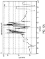
- FIG. 10A shows the line cross section of the electric field gradient along line 901 in FIG. 9 .
- FIG. 10A indicates that the electric field gradient along the cross-section is maximal near the regions proximate to the coils (within a distance of about 75 ⁇ m from the central axis) and with a value of about 10 6 V/m 2 .
- Line 901 in FIG. 10A represents the path along which the cross-section was taken in this simulation. In FIG. 10A , 0 on the x-axis corresponds the the leftmost point of line 901 in FIG.
- FIG. 10B shows the line cross section of the electric field gradient along line 902 in FIG. 9 .
- 0 on the x-axis corresponds the the lowest point of line 902 in FIG. 9 and 4 x 10 -3 on the x-axis corresponds to the topmost point of line 902.
- the width of the magntic probe in this simulated example is 200 ⁇ m.
- the magnetic probe 300 includes five electrically isolated concentric loops 351 - 355 having five different total lengths.
- the loops 351 - 355 at least partially enclose a different number of cores 332 - 335, from one core to four cores.
- the width of the loops 351 - 355 can be modified to obtain different decay depths away from the coils 332 - 335 of the electric field gradient at or above the gradient threshold value of 11000 V/m 2 .
- the edges of the loops are regions where there is a strong discontinuity in the dielectric constant of the materials across the interface. A wider loop spreads the field lines more than a narrower loop. However a narrower loop would also increase the resistance. Therefore an interplay between the current requirements and the field-narrowing requirements can be used to ascertain a loop width suitable for a particular application.
- the electric field gradient is above the threshold for neural activation up to a distance of about 125 ⁇ m away from the coils 331 - 335.
- the threshold for neural activation corresponds to an electric field gradient larger than 11000 V/m 2 .
- the threshold may be different depending on the neuron being excited.
- FIG 10B shows the electric field gradient along the longitudinal cross section. Line 902 is the path along with the longitudinal electric field gradient has been evaluated. Electric field gradients of up to 10 7 V/m 2 can be seen in regions as small as 20 ⁇ m.
- Equation 1 ⁇ 0 is the magnetic permeability of free space and ⁇ r is the relative permeability of a ferrite core.
- n is the number of turns per unit length of the solenoid and I is the current through the solenoid.
- Equation 2 z is the distance along the axis away from the coil, R is the radius of the coil, I is the current and N is the number of loops. At a given distance and for a given radius, the magnetic field can be increased by increasing the number of loops.
- the electric field gradients in the same multi-loop multi-core design are plotted along a longitudinal cross-section shown by the line 901.
- the electric field strength in the spatial electric field gradient reaching values of greater than 10 7 V/m 2 .
- the number of such spatial locations where strong electric field gradients are obtained can be adjusted by changing the number of loops and ferrite cores involved.
- the electric field gradient is higher than the neural activation threshold value of 11000 V/m 2 above the innermost core, this can be reduced by reducing the currents from the value of 50 mA used in these examples.
- FIG. 11 illustrates the operation of the disclosed magnetic probe 1100 in accordance with some embodiments.
- Probe 1100 includes at least one electrical conductor 1120 disposed on a substrate 1110 and forming at least one loop with at least one magnetic core 1130 disposed within the loop.
- probe 1100 When energized by a current through the loop, probe 1100 has an activation volume 1199 with radius Rc.
- the electric field gradient within the activation volume 1199 is generally sufficient to activate neurons and the electric field gradient outside the activation volume 1199 is generally insufficient to activate neurons.
- the activation volume in the probe with the magnetic core may be reduced by at least a few percent to about 60%, for example.
- the electric current through the loop formed by the electrical conductor 1120 may be less than about 500 mA, or less than 250 mA, or less than 100 mA, or less than 50 mA or even less than about 25 ma to obtain the electric field gradients discussed herein.
- an electric current in a range of about 25 mA to about 500 mA, e.g., a current of about 25 mA, 50 mA, about 100 mA, about 200 mA, or about 500 mA through the loop
- the probe is configured to produce a spatial electric field gradient between about 10 4 V/m 2 to about 10 7 V/m 2 within a volume around the probe.
- the volume may have a radius less than 150 ⁇ m to less than about 25 ⁇ m, for example.
- the probe may produce an electric field gradient greater than 10 4 V/m 2 inside the volume and a spatial electric field gradient less than 10 4 V/m 2 at and beyond the boundary of the volume.
- the probe may produce a spatial electric field gradient greater than 10 5 V/m 2 inside the volume and a spatial electric field gradient less than 10 5 V/m 2 at and beyond the boundary of the volume.
- the probe may produce a spatial electric field gradient greater than 10 6 V/m 2 inside the volume and a spatial electric field gradient less than 10 6 V/m 2 outside the volume.
- the probe may produce a spatial electric field gradient greater than 10 7 V/m 2 inside the volume and a spatial electric field gradient less than 10 7 V/m 2 at and beyond the boundary of the volume.
- the volume may be reduced by at least a few percent to about 60 %.
- FIG. 13 illustrates a neural stimulation system 1300 that incorporates the disclosed magnetic probe 1310.
- the probe 1310 may be configured for implantation within the body of an organism, e.g., a mammal such as a human. In various implementations, the probe 1310 may be used in vivo or in vitro.
- the electrical conductor forming the loop of the probe 1310 is electrically connected to an energizer 1320 by leads 1315.
- the energizer 1320 produces an electrical current, I, e.g., an alternating electrical current (AC current) that flows through the leads 1315 and through the loop of the probe.
- the current, I generates a magnetic field and an electric field gradient.
- the electric field gradient produced by the magnetic probe 1310 is sufficient to activate neurons within an activation volume around the probe 1310.
- the leads 1315 and/or the energizer 1320 may be configured for implantation.
- the volume of activation can be confined above the threshold value for neural stimulation of 11000 V/m 2 .
- simulations demonstrate a reduction of the radius of activation by up to 3 fold. This will thus permit driving larger currents into the loops and thus obtain larger electric field gradients, while not compromising on the selectivity of the excitation volume.
- multi-loop and multi-core magnetic probes have been designed that increase the electric field gradients produced by the probe. These designs can restrict activation depth of the probe by about 3 times when compared to probes without the cores for the same currents driven.
Abstract
Description
- This disclosure relates generally to devices, systems, and methods for magnetic stimulation of neurons.
- Neuromodulation is an evolving therapy that can involve various types of electromagnetic stimuli including the application of a strong magnetic field or a small electric current to nerve structures.
- Some embodiments are directed to an implantable magnetic neurostimulation probe. The magnetic neurostimulation probe includes at least one electrical conductor disposed on at least one substrate and arranged in at least one planar loop. At least one planar magnetic core comprising a magnetic material is disposed on the substrate and within the planar loop. A biocompatible coating is disposed over the substrate, the electrically conductive trace, and the magnetic core.
- In accordance with some embodiments, a method involves applying an electrical current of about 10 mA to 60 mA to a magnetic probe having least one electrical conductor. The electrical conductor is disposed on the substrate and is arranged as at least one planar loop. At least one magnetic core comprising a magnetic material is disposed on the substrate and within the planar loop. In response to the applied electrical current, the magnetic probe produces an excitation volume having a boundary with a radius of about 50 µm such that an electric field gradient generated by the magnetic probe is greater than 11000 V/m2 within the boundary and is less than 11000 V/m2 at and beyond the boundary.
- Some embodiments are directed to a system that comprises an implantable magnetic neurostimulation probe and an energizer electrically coupled to the probe. The implantable magnetic neurostimulation includes at least one substrate; at least one electrical conductor disposed on the substrate and arranged as at least one planar loop; at least one planar magnetic core comprising a magnetic material disposed on the substrate and within the planar loop; and
a biocompatible coating is disposed over the substrate, coil, and magnetic core. The energizer is configured to apply the electrical current through the electrical conductor. - In accordance with some embodiments and magnetic probe includes at least one electrical conductor disposed on a substrate and arranged as at least one planar loop. At least one planar magnetic core comprising a magnetic material is disposed on the substrate and within the planar loop. When energized by an electric current through the loop, the probe is configured to produce an excitation volume having an boundary with a radius of about 50 µm such that at an electric field gradient generated by the probe is greater than 11000 V/m2 within the boundary and is less than 11000 V/m2 at and beyond the boundary.
-
FIGS. 1A and 1B respectively illustrate top and side views of a magnetic probe in accordance with some embodiments; -
FIG. 2A illustrates a magnetic probe having multiple magnetic cores disposed within a single loop having a sawtooth profile in accordance with some embodiments; -
FIG. 2B illustrates some different loop section tip configurations in accordance with some embodiments; -
FIG. 3 is a diagram of a magnetic probe comprising multiple magnetic cores disposed within multiple concentric planar loops according to some embodiments; -
FIG. 4A is a top view of a magnetic probe comprising multiple coplanar electrically isolated loops according to some embodiments; -
FIG. 4B is a side view of a magnetic probe comprising multiple coplanar electrically isolated loops stacked vertically according to some embodiments; -
FIG. 5A illustrates a magnetic probe used in the implementation of a magnetic force microscope in accordance with some embodiments; -
FIG. 5B illustrates a neural probe used for neurostimulation in accordance with some embodiments; -
FIG. 6A shows a simulation of the electric field gradient dEx/dx produced by a magnetic probe as inFIG. 2 ; -
FIG. 6B shows a comparative simulation of the electric field gradient dEx/dx produced by a magnetic probe as inFIG. 2 but without the magnetic cores; -
FIG. 7A shows a simulation of the electric field gradient dEy/dy produced by a magnetic probe as inFIG. 2 ; -
FIG. 7B shows a comparative simulation of the electric field gradient dEy/dy produced by a magnetic probe as inFIG. 2 but without the magnetic cores; -
FIG. 8A shows a simulation of the electric field gradient dEz/dz produced by a magnetic probe as inFIG. 2 ; -
FIG. 8B shows a comparative simulation of the electric field gradient dEz/dz produced by a magnetic probe as inFIG. 2 but without the magnetic cores; -
FIG. 9 shows the neural probe 300 ofFIG. 3 with lateral and longitudinal cross section lines; -
FIG. 10A is a graph of the simulated electric field gradient along the lateral cross section line; -
FIG. 10B is a graph of the simulated electric field gradient along the longitudinal cross section line; -
FIG. 11 illustrates the excitation volume of a magnetic probe in accordance with some embodiments; -
FIG. 12 illustrates the excitation volume of a comparative magnetic probe that does not include magnetic cores; and -
FIG. 13 is a block diagram of a neurostimulation system in accordance with some embodiments. - Neural stimulation has the potential to treat a large number of neurological disorders. However, it can be challenging to provide effective stimulation that activates the targeted neurons without concurrently activating nearby neurons that are not targeted. Unintentional activation of non-targeted neurons leads to the spread of activation beyond the target area with undesirable or unknown results.
- When magnetically stimulated, neurons are activated by the spatial gradient of the electric field produced by an energized a magnetic coil. Magnetic coils suitable for neurostimulation can produce an electric field gradient that is sufficient to activate neurons, e.g., about 11000 V/m2, within an activation volume which extends outwardly in three dimensions from the location of the magnetic coil. The activation volume has a radius that defines the activation boundary of the spatial gradient of the electric field. The spatial gradient of the electric field is sufficient to activate neurons within the activation volume but is insufficient to activate neurons at the boundary or outside the boundary of the activation volume.
- Magnetic stimulation of neurons using implanted magnetic probes potentially has several advantages when compared to conventional electrical stimulation of neurons. The electric fields generated by implanted micro coils can be spatially asymmetrical and therefore may be more amenable to selective activation of targeted neurons than neurostimulation using conventional neuroelectrical stimulation. Furthermore, in comparison to conventional neural stimulation by electrical probes, magnetic fields more readily pass through biologic materials without substantial attenuation. Magnetic stimulation coils do not need to be placed in direct contact with the targeted neurons and can be encapsulated in biocompatible materials.
- Embodiments disclosed herein involve magnetic probes suitable for use in neural stimulation as well as other implementations. The magnetic probes incorporate micro coils which can have any suitable shape or configuration, e.g., planar or three dimensional (3D) coils. In some embodiments, the magnetic probes incorporate micro coils in the form of planar loops disposed on a substrate with high magnetic permeability cores disposed at least partially within the loops. The magnetic cores allow the planar loops to be energized by low currents that produce high electric field gradients which do not extend beyond relatively small activation volumes. The smaller activation volumes produced by the disclosed magnetic probes are useful to selectively target specific locations without affecting or minimally affecting other locations. For example, when the disclosed magnetic probes are used for magnetic neural stimulation, the activation volumes allow for activation of targeted neurons without activation of nearby non-targeted neurons. According to various implementations, the disclosed magnetic probes can produce electric field gradients greater than 1.1 x 10⁴ V/m2 within the activation volume, thus providing a spatial electric field gradient that is sufficient for the stimulation of biological nerves. These electric field gradients can be produced using an energizing current through the micro coil on the order of about 50 mA at a voltage of about 1 V.
-
FIGS. 1A and 1B are conceptual diagrams that illustrate top (FIG. 1A ) and side (FIG. 1B ) views of amagnetic probe 100 in accordance with some embodiments. Themagnetic probe 100 comprises asubstrate 110 having at least oneelectrically conductor 120 disposed on thesubstrate 110 and arranged as at least one electrically continuousplanar loop 121. A planarmagnetic core 130 comprising a magnetic material is disposed on thesubstrate 110 and at least partially within theplanar loop 121. As shown inFIGS. 1A and 1B , the planarmagnetic core 130 and theelectrical conductor 120 can be coplanar, wherein both are disposed on the same surface of thesubstrate 110. For medical applications, themagnetic probe 100 may be encapsulated within a suitablebiocompatible coating 140 which is disposed over thesubstrate 110, theelectrical conductor 120, and themagnetic core 130. - The
substrate 110 may be flat and/or rigid and may comprise materials such as silicon, germanium, sapphire, quartz and/or fused silica, among other materials. According to some implementations, theelectrical conductor 120 can be an electrically conductive trace deposited onto thesubstrate 110. Theelectrical conductor 120 can comprise various metals, including gold, silver, copper, aluminum, nickel, platinum and/or alloys thereof, for example. Themagnetic core 130 may have magnetization change per cm3mol-1 in a range of about 10 to 2000 G, for example. Suitable materials for themagnetic core 130 include ferromagnetic materials, including iron, cobalt, nickel, and/or alloys thereof. In additional examples, some ceramics, such as yttrium-based ceramics could be used. Thesubstrate 110,electrical conductor 120, andmagnetic core 130 may be at least partially or fully encapsulated by anencapsulant 140, e.g., a hermetic encapsulant and/or a biocompatible encapsulant. Suitable encapsulants include polyimide or silicon oxynitride (SiONx). - The
magnetic probe 100 may have an overall length, Lp, in a range of about 2 mm to 5 mm, an overall width, Wp, in a range of 50 µm to 200 µm, and an overall probe thickness, Tp, (which includes the thickness of the substrate, electrical conductor, magnetic core, and encapsulant) in a range of about 55 µm to about 510 µm. - The
substrate 110 can have a thickness, Ts, in a range of about 25 µm to 500 µm. - The
electrical conductor 120 may have a width, Wc, in a range of about 1 µm to about 20 µm and a thickness, Tc, in a range of about 1 µm to about 10 µm.Theelectrical conductor 120 that forms the loop can have an overall length, Lc, between about 5 mm and about 20 mm. - The
loop 121 may be rectangular, as shown inFIGS. 1A or may have any suitable shape, including planar, three dimensional coils, etc. The loop 121 (or each loop in the probe) may have a maximum length, L1, between about 2 mm and about 5 mm and a maximum width, W1, between about 30 µm and about 150 µm. - The
magnetic core 130 may have a generally rectangular shape as depicted inFIG. 1A , or may have any other suitable shape such that the magnetic core is at least partially encircled by theloop 121. For example, themagnetic core 130 may have a maximum length, Lc, between about 2 mm and 5 mm and a maximum width, Wc, between about 30 µm and about 150 µm, and a thickness, Tm, between about 1 µm and about 10 µm. - In some embodiments, the loop may have a more complex shape than the simple loop illustrated in
FIGS. 1A and 1B . - According to some embodiments, multiple magnetic cores may be disposed within a single loop of the electrical conductor, as illustrated in
FIG. 2. FIG. 2 provides a top view of amagnetic probe 200 that includes anelectrical conductor 220 disposed on asubstrate 210 and forming aplanar loop 221. Multiplemagnetic cores loop 221. In the embodiment shown inFIG. 2 , theplanar loop 221 has a stair-step or sawtooth profile along edge 250 that generally conforms to the different lengths of themagnetic cores FIG. 2 , any suitable number of magnetic cores may be at least partially encircled within theloop 221. Each of themagnetic cores magnetic cores magnetic cores FIG. 2 , one or more of themagnetic cores FIG. 2 ,magnetic core 231 is longer and has a larger surface area thanmagnetic cores magnetic core 232 is longer and has a larger surface thanmagnetic core 233. - The
magnetic cores magnetic loop 221.Magnetic core 231 is disposed within loop section 221-1;magnetic core 232 is disposed within loop section 221-2; andmagnetic core 233 is disposed within loop section 221-3. - The
magnetic probe 200 may have an overall length, in a range of about 2 mm to 5 mm, an overall width in a range of 50 µm to 200 µm, and a thickness in a range of about 2 µm to 10 µm. For example, thesubstrate 210 can have a thickness in a range of about 25 µm to 500 µm. - The
electrical conductor 220 may have a width in a range of about 1 µm to 20 µm and a thickness in a range of about 1 µm to about 10 µm. The first loop section 221-1 may have a maximum length, L11, between about 2 mm and 5 mm and a maximum width, W11, between about 30 µm and 150 µm. - According to some embodiments, the second loop section, 221-2, may have a length, L12 that is about 50 to 75% of the length, L11, of the first loop section 221-1. The third loop section, 221-3, may have a length, L13 that is about 50 to 75% of the length, L12, of the second loop section 221-2. The widths, W11, W12, W13 of the first, second and third loop sections 221-1, 221-2, 221-3 can be about the same in some embodiments.
- By virtue of the step-like pattern in the sawtooth profile, the different locations of the terminated tips 251a, 252a, 253a of the
loop 221 give control over the transverse field gradient (in the x-y plane) depending upon the insertion into the biological tissue. The sawtooth shape shown inFIG. 2A permits the control of the electric field gradients along the depth of insertion. The tips of the sawtooth coils provide for control of electric field gradients in the tranverse direction. - In
FIG. 2A , each of the tips 251a, 252a, 253a is straight and extends along the y axis However, the tips of theloop sections FIG. 2B. FIG. 2B illustrates a V-shapedtip 251b, aU-shaped tip 253b, and a W-shapedtip 252b. As illustrated inFIG. 2B , the tips of a magnetic probe need not be terminated identically. The shape of the tips permits substantial differences in the transverse field gradients and allows the transverse gradients to be shaped according to the particular application. Depending upon the coil shape, the anisotropy of the field-gradient as well as the field strength can be varied. This permits selective directional excitation of neurons. - A magnetic probe may include multiple magnetic cores disposed within multiple planar loops. In some embodiments, the multiple loops may be formed using a single electrically continuous electrical conductor, e.g., arranged in a spiral comprising multiple concentric loops. In some embodiments, the loops may be formed using multiple separate electrical conductors, e.g., multiple electrically separate concentric loops.
- An example of a magnetic probe 300 having multiple
concentric cores multiple loops FIG. 3 . In the embodiment illustrated byFIG. 3 , each core 332, 333, 334, 335 is at least partially enclosed within at least oneloop cores multiple loops 351 353, 354, 355 whileother cores 332 may be disposed withinfewer loops FIG. 3 ,loops magnetic cores loop 353 at least partially enclosescores core 332 is disposedoutside loop 353;loop 354 at least partially enclosescores cores outside loop 354;loop 355 at least partially enclosescore 335 andcores outside loop 355. As previously discussed, the geometry of at least one of the magnetic cores may be the same or may differ from the geometry of other magnetic cores. The multiple magnetic cores may have other characteristics that differ from core to core. For example, the magnetic cores may have the same or different magnetic permeability, material composition, etc. - The magnetic probe 300 may have an overall length, in a range of about 2 mm to 5 mm, an overall width in a range of 50 µm to 200 µm, and an overall thickness (including the substrate, electrical conductor, core, and encapsulant) in a range of about 51 µm to about 501 µm.The electrical conductors of loops 351 - 355 may have a width in a range of about 1 µm to 20 µm and a thickness in a range of about 1 µm to about 10 µm.
-
Loop 351 may have a maximum length, L11 between about 2 mm and 5 mm and a maximum width, W11, between about 30 µm and 150 µm. - According to some embodiments, the second loop, 352 may have a length that is about 75 to 90% of the length of the length of the
first loop 351;loop 353 may have a length that is about 50 to 75% % of the length of theloop 352;loop 354 may have a length that is about 50 to 75% % of the length ofloop 353; andloop 355 may have a length that is about 50 to 75% % of the length of loop. In some embodiments, the surface area of some of the cores can be the same, e.g.,cores FIG. 3 and the surface area of one or more of the cores can differ from the surface area of another core. For example,core 335 is wider and longer thancores - In the configuration shown in
FIG. 3 , there are a few distinct degrees of freedom that can be controlled, including magnetic core size, proximity of magnetic core to the loop, and tips of the loops, to name a few. By adjusting the parameters independent of each other, one can tailor the electric field gradient to customizable configurations with the intentional narrowing down of the spread of the field lines. By adjusting these and/or other parameters, the control of the electric field gradient can be enenhanced. - According to some embodiments, a magnetic probe can include multiple electrically non-continuous loops as illustrated by
FIGS. 4A and 4B. FIG. 4A shows a top view of amagnetic probe 400a comprisingmultiple loops loop electrical conductor electrical conductors loops loops - The
loops FIG. 4A . In the illustrated embodiment,loop 451a encloses a larger surface area thanloops loop 452a encloses a larger surface area thanloop 453a. Accordingly, theelectrical conductor 421a that formsloop 451a is longer than theelectrical conductors loops electrical conductors different loops -
Magnetic core 431a is at least partially enclosed byloop 451a;magnetic core 432a is at least partially enclosed byloop 452a; andmagnetic core 433a is at least partially enclosed byloop 453a. In themagnetic probe 400a, eachcore loops -
FIG. 4A showssingle loops loop magnetic core FIG. 3 , for example. Alternatively, each single loop may at least partially enclose multiple magnetic cores, for example, as previously discussed in connection withFIG. 2 . An encapsulant (not shown inFIG. 4A can be disposed over theloops magnetic cores -
FIG. 4B provides a side view of amagnetic probe 400b that includes multiple electrically isolated electricallyconductive loops electrical conductors loops separate substrates Magnetic cores loops - As illustrated in
FIG. 4B ,electrical conductor 421b andmagnetic core 431b are disposed on the same surface of substrate 411b.Electrical conductor 421b formsloop 451b which at least partially enclosesmagnetic core 431b.Electrical conductor 422b andmagnetic core 432b are disposed onsubstrate 412b. Theelectrical conductor 422b andmagnetic core 432b are disposed on the same surface ofsubstrate 412b.Electrical conductor 422b forms loop 452b which at least partially enclosesmagnetic core 432b.Electrical conductor 423b andmagnetic core 433b are disposed on the same surface ofsubstrate 413b.Electrical conductor 423b formsloop 453b which at least partially enclosesmagnetic core 433b. - Substrate, 411b,
loop 451b, andcore 431b form afirst portion 461 of themagnetic probe 400b; substrate, 412b, loop 452b, andcore 432b form asecond portion 462 of themagnetic probe 400b; and substrate, 413b,loop 453b, andcore 433b form athird portion 463 of themagnetic probe 400b. Anencapsulant 440 can be disposed over each of the first, second, andthird portions - According to some embodiments, each of the first, second, and
third portions FIGS. 1A and 1B . According to some embodiments, each of the first, second, andthird portions FIG. 2 . According to some embodiments, each of the first, second, andthird portions FIG. 3 . Each of the first, second, andthird portions -
FIG. 5A and 5B illustrate two technical applications for the disclosed magnetic probe. In the technical application shown inFIG. 5A , theprobe 500a is used to implement a magnetic force microscope. In this implementation, themagnetic probe 500a is moved over the surface of amagnetic sample 590. As theprobe 500a is scanned over the surface, the probe converts the magnetic fields at the surface of the sample into currents that are induced in the loop. The induced current in the loop(s) of the probe can be used to provide information about the magnetic structure of the sample surface. - In the technical application shown in
FIG. 5B , theprobe 500b is used to stimulate neurons of a nerve bundle. Theprobe 500b, placed proximate to thenerve bundle 580, is energized by supplying an electrical current through the one or more loops of theprobe 500b. The electrical current is supplied from an external source (not shown inFIG. 5B ) through the loop(s) and produces an electric field gradient sufficient to activate the targeted nerve fibers within the nerve bundle. - This design of the disclosed magnetic probe enables excitation at different locations within the spatial boundaries of a structure depending on the amplitude of the current injection in the loops.
FIGS. 6A through 8B show a comparison between the performance of a magnetic probe as generally illustrated inFIG. 2 (referred to herein as the sawtooth design) with and without the high permeability magnetic cores. The sawtooth geometry supports transverse (dEz/dz) control over the excitation volume produced by the magnetic probe. - The direct way to obtain a larger electric field gradient is to use a larger AC current excitation. However, one of the consequences of simply increasing the current in the micro coils is that the volume of excitation also increases. For example, increasing currents through a 10 µm wide Cu loop from 1 mA to 100 mA, generates an increase in a volume of excitation with radius > 150 µm.This can lead to stimulation of non-targeted regions. However, a micro-coil geometry with high permeability cores can still maintain a small excitation volume (within a radius of about 50 µm) with about 50 mA currents at electric field gradients of greater than 11000 V/m2 or even about 107 V/m2.
-
FIG. 6A shows a simulation of the electric field gradient, dEx/dx, produced by a magnetic probe as inFIG. 2 when a current of 50 mA is supplied through the loop. For comparison,FIG. 6B shows a simulation of the electric field gradient, dEx/dx, produced by a magnetic probe as inFIG. 2 but without the magnetic cores when a current of 50 mA is supplied through the loop.FIG. 7A shows a simulation of the electric field gradient, dEy/dy, produced by a magnetic probe as inFIG. 2 when a current of 50 mA is supplied through the loop. For comparison,FIG. 7B shows a simulation of the electric field gradient, dEy/dy, produced by a magnetic probe as inFIG. 2 but without the magnetic cores when a current of 50 mA is supplied through the loop.FIG. 8A shows a simulation of the electric field gradient, dEz/dz, produced by a magnetic probe as inFIG. 2 when a current of 50 mA is supplied through the loop. For comparison,FIG. 8B shows a simulation of the electric field gradient, dEz/dz, produced by a magnetic probe as inFIG. 2 but without the magnetic cores when a current of 50 mA is supplied through the loop. - In the example illustrated in
FIGS. 6A ,7A , and8A , the magnetic probes having the magnetic cores produce an electric field gradient greater than about 1.1 x 10⁴ V/m2 and/or up to about 106 V/m2 within an activation volume having a radius of about 30 µm. The electric field gradient is less than 1.1 x 10⁴ V/m2 at the boundary of the activation volume. In the comparative example, the activation volume of the magnetic probe without the magnetic cores as indicated byFIGS. 6B ,7B and8B has a radius greater than about 100 µm. Incorporating multiple magnetic cores into the loop of a magnetic probe can reduce the volume of the activation volume for neural stimulation by more than about 20 to about 70 %. For example, incorporating multiple magnetic cores into a magnetic probe as in the embodiments illustrated herein can reduce the volume of the activation volume for neural stimulation by about 60%. - Simulations were also performed for the multiple loop neural probe shown in
FIG. 3 .FIG. 9 shows the neural probe 300 ofFIG. 3 .FIG. 10A shows the line cross section of the electric field gradient alongline 901 inFIG. 9 .FIG. 10A indicates that the electric field gradient along the cross-section is maximal near the regions proximate to the coils (within a distance of about 75 µm from the central axis) and with a value of about 106 V/m2.Line 901 inFIG. 10A represents the path along which the cross-section was taken in this simulation. InFIG. 10A , 0 on the x-axis corresponds the the leftmost point ofline 901 inFIG. 9 and10 -3 on the x-axis corresponds to the rightmost point ofline 901.FIG. 10B shows the line cross section of the electric field gradient alongline 902 inFIG. 9 . InFIG. 10B , 0 on the x-axis corresponds the the lowest point ofline 902 inFIG. 9 and 4 x 10⁻³ on the x-axis corresponds to the topmost point ofline 902. - The width of the magntic probe in this simulated example is 200 µm. The magnetic probe 300 includes five electrically isolated concentric loops 351 - 355 having five different total lengths. The loops 351 - 355 at least partially enclose a different number of cores 332 - 335, from one core to four cores. The width of the loops 351 - 355 can be modified to obtain different decay depths away from the coils 332 - 335 of the electric field gradient at or above the gradient threshold value of 11000 V/m2. The edges of the loops are regions where there is a strong discontinuity in the dielectric constant of the materials across the interface. A wider loop spreads the field lines more than a narrower loop. However a narrower loop would also increase the resistance. Therefore an interplay between the current requirements and the field-narrowing requirements can be used to ascertain a loop width suitable for a particular application.
- In this example, as shown in
FIG. 10A and10B , the electric field gradient is above the threshold for neural activation up to a distance of about 125 µm away from the coils 331 - 335.. In this particular example, the threshold for neural activation corresponds to an electric field gradient larger than 11000 V/m2. However, in other scenarios, the threshold may be different depending on the neuron being excited. There is a narrow region of width of about 75 µm proximate to the coils that exhibits high electric field gradients of the order of 106 V/m2.FIG 10B shows the electric field gradient along the longitudinal cross section.Line 902 is the path along with the longitudinal electric field gradient has been evaluated. Electric field gradients of up to 107 V/m2 can be seen in regions as small as 20 µm. - The reason for such high electric-field gradients can be understood by considering that this design is similar to a 2D solenoid with a high permeability core. With the "length" of the solenoid approaching a very small number (2 µm in this case, or the corresponding thickness of the trace), when the number of loops around the core is increased which is similar to increasing the number of turns in the solenoid. From Ampere's Law and the functioning of a solenoid, it is known that the magnetic field strengths that can be generated are inversely proportional to the length of the solenoid and directly proportional to the number of turns in the solenoid. More precisely, the solenoid formula can be written as

- In Equation 1, µ0 is the magnetic permeability of free space and µr is the relative permeability of a ferrite core. In Equation 1, n is the number of turns per unit length of the solenoid and I is the current through the solenoid. Thus relatively large magnetic fields can be achieved which, when modulated via the modulation of the AC current, yields large electric field gradients as observed in the simulations. It can also be concluded from Equation 1 that the magnetic field created on-axis for a 2D current loop is as follows:

- In
Equation 2, z is the distance along the axis away from the coil, R is the radius of the coil, I is the current and N is the number of loops. At a given distance and for a given radius, the magnetic field can be increased by increasing the number of loops. - In
FIG. 10A , the electric field gradients in the same multi-loop multi-core design are plotted along a longitudinal cross-section shown by theline 901. In the several regions where the high permeability cores come in close proximity to the traces, there is a sharp increase in the electric field strength in the spatial electric field gradient, reaching values of greater than 107 V/m2. The number of such spatial locations where strong electric field gradients are obtained can be adjusted by changing the number of loops and ferrite cores involved. Although the electric field gradient is higher than the neural activation threshold value of 11000 V/m2 above the innermost core, this can be reduced by reducing the currents from the value of 50 mA used in these examples. -
FIG. 11 illustrates the operation of the disclosedmagnetic probe 1100 in accordance with some embodiments.Probe 1100 includes at least oneelectrical conductor 1120 disposed on asubstrate 1110 and forming at least one loop with at least onemagnetic core 1130 disposed within the loop. When energized by a current through the loop,probe 1100 has anactivation volume 1199 with radius Rc. The electric field gradient within theactivation volume 1199 is generally sufficient to activate neurons and the electric field gradient outside theactivation volume 1199 is generally insufficient to activate neurons. When compared to a substantially similar probe that does not include the at least one magnetic core, for the same energizing current and the same electric field gradient, the activation volume in the probe with the magnetic core may be reduced by at least a few percent to about 60%, for example. - In general, the electric current through the loop formed by the
electrical conductor 1120 may be less than about 500 mA, or less than 250 mA, or less than 100 mA, or less than 50 mA or even less than about 25 ma to obtain the electric field gradients discussed herein. When energized by an electric current in a range of about 25 mA to about 500 mA, e.g., a current of about 25 mA, 50 mA, about 100 mA, about 200 mA, or about 500 mA through the loop, the probe is configured to produce a spatial electric field gradient between about 104 V/m2 to about 107 V/m2 within a volume around the probe. The volume may have a radius less than 150 µm to less than about 25 µm, for example. For example, the probe may produce an electric field gradient greater than 104 V/m2 inside the volume and a spatial electric field gradient less than 104 V/m2 at and beyond the boundary of the volume. In another example, the probe may produce a spatial electric field gradient greater than 105 V/m2 inside the volume and a spatial electric field gradient less than 105 V/m2 at and beyond the boundary of the volume. In another example, the probe may produce a spatial electric field gradient greater than 106 V/m2 inside the volume and a spatial electric field gradient less than 106 V/m2 outside the volume. In yet another example, the probe may produce a spatial electric field gradient greater than 107 V/m2 inside the volume and a spatial electric field gradient less than 107 V/m2 at and beyond the boundary of the volume. When compared to a substantially similar probe that does not include the at least one magnetic core, for the same energizing current and the same electric field gradient, the volume may be reduced by at least a few percent to about 60 %. - As previously discussed, the magnetic probe disclosed herein finds application as a neural stimulation probe.
FIG. 13 illustrates aneural stimulation system 1300 that incorporates the disclosedmagnetic probe 1310. Theprobe 1310 may be configured for implantation within the body of an organism, e.g., a mammal such as a human. In various implementations, theprobe 1310 may be used in vivo or in vitro. The electrical conductor forming the loop of theprobe 1310 is electrically connected to anenergizer 1320 by leads 1315. Theenergizer 1320 produces an electrical current, I, e.g., an alternating electrical current (AC current) that flows through the leads 1315 and through the loop of the probe. The current, I, generates a magnetic field and an electric field gradient. When themagnetic probe 1310 is energized by the current, I, the electric field gradient produced by themagnetic probe 1310 is sufficient to activate neurons within an activation volume around theprobe 1310. In some embodiments, the leads 1315 and/or theenergizer 1320 may be configured for implantation. - By using high permeability cores, the volume of activation can be confined above the threshold value for neural stimulation of 11000 V/m2. For example, for the same current values of 15 mA, simulations demonstrate a reduction of the radius of activation by up to 3 fold. This will thus permit driving larger currents into the loops and thus obtain larger electric field gradients, while not compromising on the selectivity of the excitation volume.
- Extending the concept of a 3D solenoid or the 2D current loop to the 2D plane, multi-loop and multi-core magnetic probes have been designed that increase the electric field gradients produced by the probe. These designs can restrict activation depth of the probe by about 3 times when compared to probes without the cores for the same currents driven.
Claims (20)
- An implantable magnetic neurostimulation probe, comprising:at least one substrate;at least one electrical conductor disposed on the substrate and arranged in at least one planar loop;at least one planar magnetic core comprising a magnetic material disposed on the substrate and within the planar loop; anda biocompatible coating disposed over the substrate, electrically conductive trace, and magnetic core.
- The probe of claim 1, wherein the at least one magnetic core comprises multiple magnetic cores.
- The probe of claim 2, wherein the multiple magnetic cores include at least a first magnetic core having a first surface area and a second magnetic core having a second surface area that is different from the first surface area.
- The probe of claim 1, wherein:the electrical conductor is arranged to as the planar loop having multiple sections within the loop; andthe at least one magnetic core comprises multiple magnetic cores, each magnetic core disposed within a respective one of the multiple loop sections.
- The probe of claim 1, wherein at least one side of the planar loop has a sawtooth profile.
- The probe of claim 5, wherein the planar loop having the sawtooth profile comprises:multiple sections, each section having a different area than the area of other sections; andthe at least one magnetic core comprises multiple magnetic cores, each magnetic core having a surface area that is different from surface areas of other magnetic cores.
- The probe of claim 1, wherein the at least one planar loop is a single electrically continuous loop.
- The probe of claim 1, wherein the at least one electrical conductor comprises an electrically continuous electrical conductor that forms multiple concentric loops arranged in a spiral.
- The probe of claim 1, wherein the at least one planar loop comprises multiple planar loops.
- The probe of claim 1, wherein the multiple planar loops are concentric.
- The probe of claim 10, wherein the at least one planar magnetic core comprises multiple magnetic cores, each magnetic core disposed within a respective one of the multiple concentric planar loops.
- The probe of claim 1, wherein:the substrate is one or both of flat and rigid; andthe electrical conductor and the magnetic core conform to the substrate.
- The probe of claim 1, wherein the magnetic material has a magnetization change per cm3mol-1 in a range of about 10 to 2000 G.
- The probe of claim 1, wherein, when energized by an electric current of about 50 mA through the loop, the probe is configured to produce an excitation volume having an boundary with a radius of about 50 µm such that at an electric field gradient generated by the probe is greater than 11000 V/m2 within the boundary and is less than 11000 V/m2 at and beyond the boundary.
- The probe of claim 1 wherein the electric field gradient generated by the probe is greater than 106 V/m2 within the boundary and is less than 106 V/m2 at and beyond the boundary.
- The probe of claim 1, wherein, when energized by an electric current having a predetermined value through the loop, the probe is has an activation volume with a radius that is up to about 60 % less than a radius of an activation volume of an otherwise identical probe without the at least one magnetic core that is energized by the predetermined value of the electric current.
- A method, comprising:applying an electrical current of about 10 to 60 mA to a magnetic probe having least one electrical conductor disposed on a substrate, the electrical conductor is arranged as at least one planar loop with at least one magnetic core comprising a magnetic material disposed on the substrate and within the planar loop; andin response to the applied electrical current, the magnetic probe producing an excitation volume having a boundary with a radius of about 50 µm such that an electric field gradient generated by the magnetic probe is greater than 11000 V/m2 within the boundary and is less than 11000 V/m2 at and beyond the boundary.
- A system, comprising:an implantable magnetic neurostimulation probe comprising:at least one substrate;at least one electrical conductor disposed on the substrate and arranged as at least one planar loop;at least one planar magnetic core comprising a magnetic material disposed on the substrate and within the planar loop; anda biocompatible coating disposed over the substrate, coil, and magnetic core; andan energizer configured to apply an electrical current through the electrical conductor.
- A magnetic probe, comprising:at least one substrate;at least one electrical conductor disposed on the substrate and arranged as at least one planar loop; andat least one planar magnetic core comprising a magnetic material disposed on the substrate and within the planar loop, wherein, when energized by an electric current through the loop, the probe is configured to produce an excitation volume having an boundary with a radius of about 50 µm such that at an electric field gradient generated by the probe is greater than 11000 V/m2 within the boundary and is less than 11000 V/m2 at and beyond the boundary.
- The probe of claim 19, wherein the electric field gradient generated by the probe is greater than 106 V/m2 within the boundary and is less than 106 V/m2 at and beyond the boundary.
Applications Claiming Priority (1)
| Application Number | Priority Date | Filing Date | Title |
|---|---|---|---|
| US15/922,693 US11110289B2 (en) | 2018-03-15 | 2018-03-15 | Micro coils suitable for magnetic neural stimulation |
Publications (3)
| Publication Number | Publication Date |
|---|---|
| EP3539614A2 true EP3539614A2 (en) | 2019-09-18 |
| EP3539614A3 EP3539614A3 (en) | 2020-01-08 |
| EP3539614B1 EP3539614B1 (en) | 2022-05-11 |
Family
ID=65801930
Family Applications (1)
| Application Number | Title | Priority Date | Filing Date |
|---|---|---|---|
| EP19162392.5A Active EP3539614B1 (en) | 2018-03-15 | 2019-03-12 | Micro coils suitable for magnetic neural stimulation |
Country Status (3)
| Country | Link |
|---|---|
| US (2) | US11110289B2 (en) |
| EP (1) | EP3539614B1 (en) |
| JP (1) | JP7137494B2 (en) |
Families Citing this family (2)
| Publication number | Priority date | Publication date | Assignee | Title |
|---|---|---|---|---|
| US20200129778A1 (en) * | 2018-10-25 | 2020-04-30 | Northeastern University | Micro-Solenoid Inductors With Magnetic Core for Neural Stimulation |
| CN114933277B (en) * | 2022-07-22 | 2022-09-20 | 中国电子科技集团公司第五十八研究所 | Packaging method of implantable magnetic field stimulation probe device |
Family Cites Families (19)
| Publication number | Priority date | Publication date | Assignee | Title |
|---|---|---|---|---|
| US7103413B2 (en) | 2002-07-12 | 2006-09-05 | Cardiac Pacemakers, Inc. | Ferrite core telemetry coil for implantable medical device |
| US20040181261A1 (en) | 2002-12-16 | 2004-09-16 | Joseph Manne | Cavernous nerve stimulation device |
| US8868177B2 (en) | 2009-03-20 | 2014-10-21 | ElectroCore, LLC | Non-invasive treatment of neurodegenerative diseases |
| US20110125203A1 (en) | 2009-03-20 | 2011-05-26 | ElectroCore, LLC. | Magnetic Stimulation Devices and Methods of Therapy |
| US8412332B2 (en) | 2007-10-18 | 2013-04-02 | Integrated Sensing Systems, Inc. | Miniature wireless system for deep brain stimulation |
| US8457757B2 (en) | 2007-11-26 | 2013-06-04 | Micro Transponder, Inc. | Implantable transponder systems and methods |
| US20110288615A1 (en) | 2007-11-26 | 2011-11-24 | The Board Of Regents, The University Of Texas System | Implantable Therapeutic Systems Including Neurostimulation Circuits, Devices, Systems and Methods |
| US8944985B2 (en) * | 2008-04-03 | 2015-02-03 | The General Hospital Corporation | Deep brain stimulation implant with microcoil array |
| JP2012508640A (en) | 2008-11-13 | 2012-04-12 | コーニンクレッカ フィリップス エレクトロニクス エヌ ヴィ | Spiral wire in probe of deep brain stimulator |
| EP2369985A4 (en) | 2008-11-30 | 2014-02-12 | Purdue Research Foundation | Flexible neural probe for magnetic insertion |
| US8494641B2 (en) | 2009-04-22 | 2013-07-23 | Autonomic Technologies, Inc. | Implantable neurostimulator with integral hermetic electronic enclosure, circuit substrate, monolithic feed-through, lead assembly and anchoring mechanism |
| JP6000126B2 (en) | 2009-12-21 | 2016-09-28 | フア,シャーウィン | Insertion and use of medical devices through non-orthogonal and orthogonal pathways within the skull |
| WO2014016694A2 (en) * | 2012-07-26 | 2014-01-30 | Adi Mashiach | Internal resonance matching between an implanted device and an external device |
| WO2014197435A1 (en) | 2013-06-03 | 2014-12-11 | The General Hospital Corporation | Magnetic neural stimulator and method of activatioin of neural tissue with same |
| US20150080637A1 (en) | 2013-09-16 | 2015-03-19 | The General Hospital Corporation | Microscopic magnetic coils for neural stimulation |
| US9999781B2 (en) | 2014-05-13 | 2018-06-19 | The Cleveland Clinic Foundation | System and method for micromagnetic stimulation of the peripheral nervous system |
| WO2017127758A1 (en) | 2016-01-20 | 2017-07-27 | Setpoint Medical Corporation | Implantable microstimulators and inductive charging systems |
| US10307607B2 (en) | 2016-02-09 | 2019-06-04 | Palo Alto Research Center Incorporated | Focused magnetic stimulation for modulation of nerve circuits |
| KR101866199B1 (en) | 2016-04-27 | 2018-06-12 | 한국과학기술연구원 | Neural probe structure comprising coil embedded therein and method for manufacturing the same |
-
2018
- 2018-03-15 US US15/922,693 patent/US11110289B2/en active Active
-
2019
- 2019-02-22 JP JP2019031028A patent/JP7137494B2/en active Active
- 2019-03-12 EP EP19162392.5A patent/EP3539614B1/en active Active
-
2021
- 2021-08-12 US US17/400,578 patent/US20210370087A1/en active Pending
Non-Patent Citations (1)
| Title |
|---|
| None |
Also Published As
| Publication number | Publication date |
|---|---|
| EP3539614B1 (en) | 2022-05-11 |
| US20190282825A1 (en) | 2019-09-19 |
| EP3539614A3 (en) | 2020-01-08 |
| JP2019155087A (en) | 2019-09-19 |
| US11110289B2 (en) | 2021-09-07 |
| US20210370087A1 (en) | 2021-12-02 |
| JP7137494B2 (en) | 2022-09-14 |
Similar Documents
| Publication | Publication Date | Title |
|---|---|---|
| US20210370087A1 (en) | Micro coils suitable for magnetic neural stimulation | |
| US9993656B2 (en) | Magnetic neural stimulator and method of activation of neural tissue with same | |
| US20150080637A1 (en) | Microscopic magnetic coils for neural stimulation | |
| US8944985B2 (en) | Deep brain stimulation implant with microcoil array | |
| US20050038489A1 (en) | Electrode array for use in medical stimulation and methods thereof | |
| US20050222659A1 (en) | Lead electrode for use in an MRI-safe implantable medical device | |
| Slopsema et al. | Clinical deep brain stimulation strategies for orientation-selective pathway activation | |
| KR101866199B1 (en) | Neural probe structure comprising coil embedded therein and method for manufacturing the same | |
| WO2014164412A2 (en) | Electromagnetic cortical stimulation device | |
| Carbunaru et al. | Toroidal coil models for transcutaneous magnetic simulation of nerves | |
| US20190201708A1 (en) | Magnetic stimulation probe | |
| US11007372B2 (en) | Selective activation of cortex using bent micro wires to magnetically stimulate neurons | |
| Saha et al. | A review on magnetic and spintronic neurostimulation: challenges and prospects | |
| EP3550578B1 (en) | Coil core in the form of a ferromagnetic rivet for spiral inductors on printed circuit boards | |
| CN110957103B (en) | Magnetic field generator for biostimulation | |
| EP3533487B1 (en) | Localized electromagnetic field control in implantable biomedical probes using smart polymers | |
| Yamaguchi et al. | Electromagnetic mechanism of magnetic nerve stimulation | |
| KR101985212B1 (en) | Neural stimulation probe | |
| CN115715217A (en) | Method and apparatus for modulating nerve bundles in neural tissue | |
| US20220241605A1 (en) | System and method for multi-coil steerable and selectively focussed transcranial magnetic stimulation | |
| US20200129778A1 (en) | Micro-Solenoid Inductors With Magnetic Core for Neural Stimulation | |
| Szoka et al. | Neural Probe Utilizing Programmable Micro-coil Magnetic Stimulation | |
| CN113476050B (en) | Nerve microprobe and preparation method thereof | |
| US11794002B2 (en) | Neuromodulation probe | |
| Ge et al. | Orientationally Selective micro-Coil Design of Intracortical Magnetic Neurostimulation |
Legal Events
| Date | Code | Title | Description |
|---|---|---|---|
| PUAI | Public reference made under article 153(3) epc to a published international application that has entered the european phase |
Free format text: ORIGINAL CODE: 0009012 |
|
| STAA | Information on the status of an ep patent application or granted ep patent |
Free format text: STATUS: THE APPLICATION HAS BEEN PUBLISHED |
|
| AK | Designated contracting states |
Kind code of ref document: A2 Designated state(s): AL AT BE BG CH CY CZ DE DK EE ES FI FR GB GR HR HU IE IS IT LI LT LU LV MC MK MT NL NO PL PT RO RS SE SI SK SM TR |
|
| AX | Request for extension of the european patent |
Extension state: BA ME |
|
| PUAL | Search report despatched |
Free format text: ORIGINAL CODE: 0009013 |
|
| AK | Designated contracting states |
Kind code of ref document: A3 Designated state(s): AL AT BE BG CH CY CZ DE DK EE ES FI FR GB GR HR HU IE IS IT LI LT LU LV MC MK MT NL NO PL PT RO RS SE SI SK SM TR |
|
| AX | Request for extension of the european patent |
Extension state: BA ME |
|
| RIC1 | Information provided on ipc code assigned before grant |
Ipc: A61N 1/40 20060101ALN20191205BHEP Ipc: A61N 2/02 20060101AFI20191205BHEP |
|
| STAA | Information on the status of an ep patent application or granted ep patent |
Free format text: STATUS: REQUEST FOR EXAMINATION WAS MADE |
|
| 17P | Request for examination filed |
Effective date: 20200708 |
|
| RBV | Designated contracting states (corrected) |
Designated state(s): AL AT BE BG CH CY CZ DE DK EE ES FI FR GB GR HR HU IE IS IT LI LT LU LV MC MK MT NL NO PL PT RO RS SE SI SK SM TR |
|
| GRAP | Despatch of communication of intention to grant a patent |
Free format text: ORIGINAL CODE: EPIDOSNIGR1 |
|
| STAA | Information on the status of an ep patent application or granted ep patent |
Free format text: STATUS: GRANT OF PATENT IS INTENDED |
|
| RIC1 | Information provided on ipc code assigned before grant |
Ipc: A61N 1/40 20060101ALN20211014BHEP Ipc: A61N 2/02 20060101AFI20211014BHEP |
|
| RIC1 | Information provided on ipc code assigned before grant |
Ipc: A61N 1/40 20060101ALN20211020BHEP Ipc: A61N 2/02 20060101AFI20211020BHEP |
|
| INTG | Intention to grant announced |
Effective date: 20211105 |
|
| GRAS | Grant fee paid |
Free format text: ORIGINAL CODE: EPIDOSNIGR3 |
|
| GRAA | (expected) grant |
Free format text: ORIGINAL CODE: 0009210 |
|
| STAA | Information on the status of an ep patent application or granted ep patent |
Free format text: STATUS: THE PATENT HAS BEEN GRANTED |
|
| AK | Designated contracting states |
Kind code of ref document: B1 Designated state(s): AL AT BE BG CH CY CZ DE DK EE ES FI FR GB GR HR HU IE IS IT LI LT LU LV MC MK MT NL NO PL PT RO RS SE SI SK SM TR |
|
| REG | Reference to a national code |
Ref country code: GB Ref legal event code: FG4D |
|
| REG | Reference to a national code |
Ref country code: CH Ref legal event code: EP |
|
| REG | Reference to a national code |
Ref country code: AT Ref legal event code: REF Ref document number: 1490877 Country of ref document: AT Kind code of ref document: T Effective date: 20220515 |
|
| REG | Reference to a national code |
Ref country code: DE Ref legal event code: R096 Ref document number: 602019014723 Country of ref document: DE |
|
| REG | Reference to a national code |
Ref country code: IE Ref legal event code: FG4D |
|
| REG | Reference to a national code |
Ref country code: LT Ref legal event code: MG9D |
|
| REG | Reference to a national code |
Ref country code: NL Ref legal event code: MP Effective date: 20220511 |
|
| REG | Reference to a national code |
Ref country code: AT Ref legal event code: MK05 Ref document number: 1490877 Country of ref document: AT Kind code of ref document: T Effective date: 20220511 |
|
| PG25 | Lapsed in a contracting state [announced via postgrant information from national office to epo] |
Ref country code: SE Free format text: LAPSE BECAUSE OF FAILURE TO SUBMIT A TRANSLATION OF THE DESCRIPTION OR TO PAY THE FEE WITHIN THE PRESCRIBED TIME-LIMIT Effective date: 20220511 Ref country code: PT Free format text: LAPSE BECAUSE OF FAILURE TO SUBMIT A TRANSLATION OF THE DESCRIPTION OR TO PAY THE FEE WITHIN THE PRESCRIBED TIME-LIMIT Effective date: 20220912 Ref country code: NO Free format text: LAPSE BECAUSE OF FAILURE TO SUBMIT A TRANSLATION OF THE DESCRIPTION OR TO PAY THE FEE WITHIN THE PRESCRIBED TIME-LIMIT Effective date: 20220811 Ref country code: NL Free format text: LAPSE BECAUSE OF FAILURE TO SUBMIT A TRANSLATION OF THE DESCRIPTION OR TO PAY THE FEE WITHIN THE PRESCRIBED TIME-LIMIT Effective date: 20220511 Ref country code: LT Free format text: LAPSE BECAUSE OF FAILURE TO SUBMIT A TRANSLATION OF THE DESCRIPTION OR TO PAY THE FEE WITHIN THE PRESCRIBED TIME-LIMIT Effective date: 20220511 Ref country code: HR Free format text: LAPSE BECAUSE OF FAILURE TO SUBMIT A TRANSLATION OF THE DESCRIPTION OR TO PAY THE FEE WITHIN THE PRESCRIBED TIME-LIMIT Effective date: 20220511 Ref country code: GR Free format text: LAPSE BECAUSE OF FAILURE TO SUBMIT A TRANSLATION OF THE DESCRIPTION OR TO PAY THE FEE WITHIN THE PRESCRIBED TIME-LIMIT Effective date: 20220812 Ref country code: FI Free format text: LAPSE BECAUSE OF FAILURE TO SUBMIT A TRANSLATION OF THE DESCRIPTION OR TO PAY THE FEE WITHIN THE PRESCRIBED TIME-LIMIT Effective date: 20220511 Ref country code: ES Free format text: LAPSE BECAUSE OF FAILURE TO SUBMIT A TRANSLATION OF THE DESCRIPTION OR TO PAY THE FEE WITHIN THE PRESCRIBED TIME-LIMIT Effective date: 20220511 Ref country code: BG Free format text: LAPSE BECAUSE OF FAILURE TO SUBMIT A TRANSLATION OF THE DESCRIPTION OR TO PAY THE FEE WITHIN THE PRESCRIBED TIME-LIMIT Effective date: 20220811 Ref country code: AT Free format text: LAPSE BECAUSE OF FAILURE TO SUBMIT A TRANSLATION OF THE DESCRIPTION OR TO PAY THE FEE WITHIN THE PRESCRIBED TIME-LIMIT Effective date: 20220511 |
|
| PG25 | Lapsed in a contracting state [announced via postgrant information from national office to epo] |
Ref country code: RS Free format text: LAPSE BECAUSE OF FAILURE TO SUBMIT A TRANSLATION OF THE DESCRIPTION OR TO PAY THE FEE WITHIN THE PRESCRIBED TIME-LIMIT Effective date: 20220511 Ref country code: PL Free format text: LAPSE BECAUSE OF FAILURE TO SUBMIT A TRANSLATION OF THE DESCRIPTION OR TO PAY THE FEE WITHIN THE PRESCRIBED TIME-LIMIT Effective date: 20220511 Ref country code: LV Free format text: LAPSE BECAUSE OF FAILURE TO SUBMIT A TRANSLATION OF THE DESCRIPTION OR TO PAY THE FEE WITHIN THE PRESCRIBED TIME-LIMIT Effective date: 20220511 Ref country code: IS Free format text: LAPSE BECAUSE OF FAILURE TO SUBMIT A TRANSLATION OF THE DESCRIPTION OR TO PAY THE FEE WITHIN THE PRESCRIBED TIME-LIMIT Effective date: 20220911 |
|
| PG25 | Lapsed in a contracting state [announced via postgrant information from national office to epo] |
Ref country code: SM Free format text: LAPSE BECAUSE OF FAILURE TO SUBMIT A TRANSLATION OF THE DESCRIPTION OR TO PAY THE FEE WITHIN THE PRESCRIBED TIME-LIMIT Effective date: 20220511 Ref country code: SK Free format text: LAPSE BECAUSE OF FAILURE TO SUBMIT A TRANSLATION OF THE DESCRIPTION OR TO PAY THE FEE WITHIN THE PRESCRIBED TIME-LIMIT Effective date: 20220511 Ref country code: RO Free format text: LAPSE BECAUSE OF FAILURE TO SUBMIT A TRANSLATION OF THE DESCRIPTION OR TO PAY THE FEE WITHIN THE PRESCRIBED TIME-LIMIT Effective date: 20220511 Ref country code: EE Free format text: LAPSE BECAUSE OF FAILURE TO SUBMIT A TRANSLATION OF THE DESCRIPTION OR TO PAY THE FEE WITHIN THE PRESCRIBED TIME-LIMIT Effective date: 20220511 Ref country code: DK Free format text: LAPSE BECAUSE OF FAILURE TO SUBMIT A TRANSLATION OF THE DESCRIPTION OR TO PAY THE FEE WITHIN THE PRESCRIBED TIME-LIMIT Effective date: 20220511 Ref country code: CZ Free format text: LAPSE BECAUSE OF FAILURE TO SUBMIT A TRANSLATION OF THE DESCRIPTION OR TO PAY THE FEE WITHIN THE PRESCRIBED TIME-LIMIT Effective date: 20220511 |
|
| REG | Reference to a national code |
Ref country code: DE Ref legal event code: R097 Ref document number: 602019014723 Country of ref document: DE |
|
| PLBE | No opposition filed within time limit |
Free format text: ORIGINAL CODE: 0009261 |
|
| STAA | Information on the status of an ep patent application or granted ep patent |
Free format text: STATUS: NO OPPOSITION FILED WITHIN TIME LIMIT |
|
| PG25 | Lapsed in a contracting state [announced via postgrant information from national office to epo] |
Ref country code: AL Free format text: LAPSE BECAUSE OF FAILURE TO SUBMIT A TRANSLATION OF THE DESCRIPTION OR TO PAY THE FEE WITHIN THE PRESCRIBED TIME-LIMIT Effective date: 20220511 |
|
| 26N | No opposition filed |
Effective date: 20230214 |
|
| PGFP | Annual fee paid to national office [announced via postgrant information from national office to epo] |
Ref country code: FR Payment date: 20230222 Year of fee payment: 5 |
|
| PG25 | Lapsed in a contracting state [announced via postgrant information from national office to epo] |
Ref country code: SI Free format text: LAPSE BECAUSE OF FAILURE TO SUBMIT A TRANSLATION OF THE DESCRIPTION OR TO PAY THE FEE WITHIN THE PRESCRIBED TIME-LIMIT Effective date: 20220511 |
|
| PGFP | Annual fee paid to national office [announced via postgrant information from national office to epo] |
Ref country code: GB Payment date: 20230221 Year of fee payment: 5 Ref country code: DE Payment date: 20230221 Year of fee payment: 5 |
|
| PG25 | Lapsed in a contracting state [announced via postgrant information from national office to epo] |
Ref country code: MC Free format text: LAPSE BECAUSE OF FAILURE TO SUBMIT A TRANSLATION OF THE DESCRIPTION OR TO PAY THE FEE WITHIN THE PRESCRIBED TIME-LIMIT Effective date: 20220511 |
|
| REG | Reference to a national code |
Ref country code: CH Ref legal event code: PL |
|
| REG | Reference to a national code |
Ref country code: BE Ref legal event code: MM Effective date: 20230331 |
|
| PG25 | Lapsed in a contracting state [announced via postgrant information from national office to epo] |
Ref country code: LU Free format text: LAPSE BECAUSE OF NON-PAYMENT OF DUE FEES Effective date: 20230312 |
|
| REG | Reference to a national code |
Ref country code: IE Ref legal event code: MM4A |
|
| PG25 | Lapsed in a contracting state [announced via postgrant information from national office to epo] |
Ref country code: LI Free format text: LAPSE BECAUSE OF NON-PAYMENT OF DUE FEES Effective date: 20230331 Ref country code: IT Free format text: LAPSE BECAUSE OF FAILURE TO SUBMIT A TRANSLATION OF THE DESCRIPTION OR TO PAY THE FEE WITHIN THE PRESCRIBED TIME-LIMIT Effective date: 20220511 Ref country code: IE Free format text: LAPSE BECAUSE OF NON-PAYMENT OF DUE FEES Effective date: 20230312 Ref country code: CH Free format text: LAPSE BECAUSE OF NON-PAYMENT OF DUE FEES Effective date: 20230331 |
|
| PG25 | Lapsed in a contracting state [announced via postgrant information from national office to epo] |
Ref country code: BE Free format text: LAPSE BECAUSE OF NON-PAYMENT OF DUE FEES Effective date: 20230331 |