EP3539578A2 - Negative pressure generator and automatic negative pressure wound treatment apparatus using same to have pressure change function - Google Patents
Negative pressure generator and automatic negative pressure wound treatment apparatus using same to have pressure change function Download PDFInfo
- Publication number
- EP3539578A2 EP3539578A2 EP17870523.2A EP17870523A EP3539578A2 EP 3539578 A2 EP3539578 A2 EP 3539578A2 EP 17870523 A EP17870523 A EP 17870523A EP 3539578 A2 EP3539578 A2 EP 3539578A2
- Authority
- EP
- European Patent Office
- Prior art keywords
- negative pressure
- unit
- rotating unit
- generating device
- rotating
- Prior art date
- Legal status (The legal status is an assumption and is not a legal conclusion. Google has not performed a legal analysis and makes no representation as to the accuracy of the status listed.)
- Granted
Links
Images


Classifications
-
- A—HUMAN NECESSITIES
- A61—MEDICAL OR VETERINARY SCIENCE; HYGIENE
- A61M—DEVICES FOR INTRODUCING MEDIA INTO, OR ONTO, THE BODY; DEVICES FOR TRANSDUCING BODY MEDIA OR FOR TAKING MEDIA FROM THE BODY; DEVICES FOR PRODUCING OR ENDING SLEEP OR STUPOR
- A61M1/00—Suction or pumping devices for medical purposes; Devices for carrying-off, for treatment of, or for carrying-over, body-liquids; Drainage systems
- A61M1/71—Suction drainage systems
- A61M1/73—Suction drainage systems comprising sensors or indicators for physical values
- A61M1/732—Visual indicating means for vacuum pressure
-
- A—HUMAN NECESSITIES
- A61—MEDICAL OR VETERINARY SCIENCE; HYGIENE
- A61M—DEVICES FOR INTRODUCING MEDIA INTO, OR ONTO, THE BODY; DEVICES FOR TRANSDUCING BODY MEDIA OR FOR TAKING MEDIA FROM THE BODY; DEVICES FOR PRODUCING OR ENDING SLEEP OR STUPOR
- A61M1/00—Suction or pumping devices for medical purposes; Devices for carrying-off, for treatment of, or for carrying-over, body-liquids; Drainage systems
-
- A—HUMAN NECESSITIES
- A61—MEDICAL OR VETERINARY SCIENCE; HYGIENE
- A61M—DEVICES FOR INTRODUCING MEDIA INTO, OR ONTO, THE BODY; DEVICES FOR TRANSDUCING BODY MEDIA OR FOR TAKING MEDIA FROM THE BODY; DEVICES FOR PRODUCING OR ENDING SLEEP OR STUPOR
- A61M1/00—Suction or pumping devices for medical purposes; Devices for carrying-off, for treatment of, or for carrying-over, body-liquids; Drainage systems
- A61M1/60—Containers for suction drainage, adapted to be used with an external suction source
-
- A—HUMAN NECESSITIES
- A61—MEDICAL OR VETERINARY SCIENCE; HYGIENE
- A61M—DEVICES FOR INTRODUCING MEDIA INTO, OR ONTO, THE BODY; DEVICES FOR TRANSDUCING BODY MEDIA OR FOR TAKING MEDIA FROM THE BODY; DEVICES FOR PRODUCING OR ENDING SLEEP OR STUPOR
- A61M1/00—Suction or pumping devices for medical purposes; Devices for carrying-off, for treatment of, or for carrying-over, body-liquids; Drainage systems
- A61M1/71—Suction drainage systems
- A61M1/74—Suction control
-
- A—HUMAN NECESSITIES
- A61—MEDICAL OR VETERINARY SCIENCE; HYGIENE
- A61M—DEVICES FOR INTRODUCING MEDIA INTO, OR ONTO, THE BODY; DEVICES FOR TRANSDUCING BODY MEDIA OR FOR TAKING MEDIA FROM THE BODY; DEVICES FOR PRODUCING OR ENDING SLEEP OR STUPOR
- A61M1/00—Suction or pumping devices for medical purposes; Devices for carrying-off, for treatment of, or for carrying-over, body-liquids; Drainage systems
- A61M1/80—Suction pumps
- A61M1/81—Piston pumps, e.g. syringes
-
- A—HUMAN NECESSITIES
- A61—MEDICAL OR VETERINARY SCIENCE; HYGIENE
- A61M—DEVICES FOR INTRODUCING MEDIA INTO, OR ONTO, THE BODY; DEVICES FOR TRANSDUCING BODY MEDIA OR FOR TAKING MEDIA FROM THE BODY; DEVICES FOR PRODUCING OR ENDING SLEEP OR STUPOR
- A61M1/00—Suction or pumping devices for medical purposes; Devices for carrying-off, for treatment of, or for carrying-over, body-liquids; Drainage systems
- A61M1/84—Drainage tubes; Aspiration tips
- A61M1/842—Drainage tubes; Aspiration tips rotating
-
- A—HUMAN NECESSITIES
- A61—MEDICAL OR VETERINARY SCIENCE; HYGIENE
- A61M—DEVICES FOR INTRODUCING MEDIA INTO, OR ONTO, THE BODY; DEVICES FOR TRANSDUCING BODY MEDIA OR FOR TAKING MEDIA FROM THE BODY; DEVICES FOR PRODUCING OR ENDING SLEEP OR STUPOR
- A61M1/00—Suction or pumping devices for medical purposes; Devices for carrying-off, for treatment of, or for carrying-over, body-liquids; Drainage systems
- A61M1/90—Negative pressure wound therapy devices, i.e. devices for applying suction to a wound to promote healing, e.g. including a vacuum dressing
- A61M1/96—Suction control thereof
-
- A—HUMAN NECESSITIES
- A61—MEDICAL OR VETERINARY SCIENCE; HYGIENE
- A61M—DEVICES FOR INTRODUCING MEDIA INTO, OR ONTO, THE BODY; DEVICES FOR TRANSDUCING BODY MEDIA OR FOR TAKING MEDIA FROM THE BODY; DEVICES FOR PRODUCING OR ENDING SLEEP OR STUPOR
- A61M2205/00—General characteristics of the apparatus
- A61M2205/10—General characteristics of the apparatus with powered movement mechanisms
- A61M2205/103—General characteristics of the apparatus with powered movement mechanisms rotating
-
- A—HUMAN NECESSITIES
- A61—MEDICAL OR VETERINARY SCIENCE; HYGIENE
- A61M—DEVICES FOR INTRODUCING MEDIA INTO, OR ONTO, THE BODY; DEVICES FOR TRANSDUCING BODY MEDIA OR FOR TAKING MEDIA FROM THE BODY; DEVICES FOR PRODUCING OR ENDING SLEEP OR STUPOR
- A61M2205/00—General characteristics of the apparatus
- A61M2205/27—General characteristics of the apparatus preventing use
- A61M2205/273—General characteristics of the apparatus preventing use preventing reuse, e.g. of disposables
-
- A—HUMAN NECESSITIES
- A61—MEDICAL OR VETERINARY SCIENCE; HYGIENE
- A61M—DEVICES FOR INTRODUCING MEDIA INTO, OR ONTO, THE BODY; DEVICES FOR TRANSDUCING BODY MEDIA OR FOR TAKING MEDIA FROM THE BODY; DEVICES FOR PRODUCING OR ENDING SLEEP OR STUPOR
- A61M2205/00—General characteristics of the apparatus
- A61M2205/33—Controlling, regulating or measuring
- A61M2205/3331—Pressure; Flow
- A61M2205/3334—Measuring or controlling the flow rate
-
- A—HUMAN NECESSITIES
- A61—MEDICAL OR VETERINARY SCIENCE; HYGIENE
- A61M—DEVICES FOR INTRODUCING MEDIA INTO, OR ONTO, THE BODY; DEVICES FOR TRANSDUCING BODY MEDIA OR FOR TAKING MEDIA FROM THE BODY; DEVICES FOR PRODUCING OR ENDING SLEEP OR STUPOR
- A61M2205/00—General characteristics of the apparatus
- A61M2205/82—Internal energy supply devices
- A61M2205/8275—Mechanical
- A61M2205/8281—Mechanical spring operated
-
- F—MECHANICAL ENGINEERING; LIGHTING; HEATING; WEAPONS; BLASTING
- F03—MACHINES OR ENGINES FOR LIQUIDS; WIND, SPRING, OR WEIGHT MOTORS; PRODUCING MECHANICAL POWER OR A REACTIVE PROPULSIVE THRUST, NOT OTHERWISE PROVIDED FOR
- F03G—SPRING, WEIGHT, INERTIA OR LIKE MOTORS; MECHANICAL-POWER PRODUCING DEVICES OR MECHANISMS, NOT OTHERWISE PROVIDED FOR OR USING ENERGY SOURCES NOT OTHERWISE PROVIDED FOR
- F03G1/00—Spring motors
-
- F—MECHANICAL ENGINEERING; LIGHTING; HEATING; WEAPONS; BLASTING
- F04—POSITIVE - DISPLACEMENT MACHINES FOR LIQUIDS; PUMPS FOR LIQUIDS OR ELASTIC FLUIDS
- F04B—POSITIVE-DISPLACEMENT MACHINES FOR LIQUIDS; PUMPS
- F04B53/00—Component parts, details or accessories not provided for in, or of interest apart from, groups F04B1/00 - F04B23/00 or F04B39/00 - F04B47/00
- F04B53/14—Pistons, piston-rods or piston-rod connections
-
- F—MECHANICAL ENGINEERING; LIGHTING; HEATING; WEAPONS; BLASTING
- F04—POSITIVE - DISPLACEMENT MACHINES FOR LIQUIDS; PUMPS FOR LIQUIDS OR ELASTIC FLUIDS
- F04C—ROTARY-PISTON, OR OSCILLATING-PISTON, POSITIVE-DISPLACEMENT MACHINES FOR LIQUIDS; ROTARY-PISTON, OR OSCILLATING-PISTON, POSITIVE-DISPLACEMENT PUMPS
- F04C2220/00—Application
- F04C2220/10—Vacuum
Definitions
- the present invention relates to a negative pressure generating device and an automatic negative pressure wound therapy device having a pressure changing function, and more particularly, to a negative pressure generating device which is used for treatment, such as the discharge of blood or exudates at a surgical site, is easy to carry and includes a negative pressure changing function.
- the negative pressure wound therapy device actively promotes wound healing so that the usage of the negative pressure wound therapy device has been gradually increasing in recent years.
- the usage of vacuum negative pressure devices is increasing in recent years and products which reduce the risk of infection and are easy to carry are being developed.
- a vacuum negative pressure device applies a negative pressure to a wounded site of a patient to suck exudates such as blood and oozing fluids and promote blood circulation of the wounded site to induce rapid wound healing.
- a vacuum negative pressure device is configured by a foam dressing which covers the wound, a pump which generates a negative pressure, and a liquid tank which stores exudates so that the volume thereof is large. Therefore, there are problems in that it is difficult to carry the vacuum negative pressure device and it is not easy for the patient to be discharged from the hospital, and to move in daily life while using the vacuum negative pressure device.
- the vacuum negative pressure device is an electrically powered device using an expensive component such as a pump operating by electricity, there is another problem in that it is not easy to use the vacuum negative pressure device in developing countries where medical conditions are insufficient. Further, since the vacuum negative pressure device is an expensive device, it may be considered to reuse the vacuum negative pressure device. However, in this case, there is a risk of infection.
- the present invention has been made to solve the problems of the related art as described above and an object of the present invention is to provide a negative pressure generating device which is mechanically operated and consistently forms a negative pressure with a constant magnitude.
- Another object of the present invention is to change a negative pressure in a negative pressure generating device which is mechanically operated.
- the present invention includes a static load elastic unit which provides an elastic force having a predetermined magnitude; a rotating unit which is connected to the static load elastic unit to rotate by the static load elastic unit; and a negative pressure cylinder which is connected to the rotating unit and interworks with the rotation of the rotating unit to generate a negative pressure therein.
- the negative pressure cylinder includes: a cylinder housing; a piston which is linearly movably installed in the cylinder housing; and a connecting unit which connects the piston and the static load elastic unit.
- An interlocking assembly is provided between the rotating unit and the negative pressure cylinder to connect to each other and the interlocking assembly is connected to the piston of the negative pressure cylinder to generate the negative pressure while pulling the piston by a torque of the rotating unit.
- the interlocking assembly includes: a winder which winds a wire while rotating coaxially with the rotating unit; and a pulley which is installed to be adjacent to the winder and supports the wire or changes a movement path of the wire, one end of the wire is connected to the wire to be continuously wound and the other end is connected to the connecting unit of the negative pressure cylinder via the pulley to pull the piston.
- a diameter of the rotating unit is larger than the winder of the interlocking assembly.
- the rotating unit includes a negative pressure changing unit which interferes with the rotating unit to adjust a torque of the rotating unit.
- an interfering protrusion which selectively locks gear teeth provided on an outer circumferential surface of the rotating unit to adjust a torque is provided to be movable to the outer circumferential surface of the rotating unit and the negative pressure changing unit includes an elastic member which elastically supports the interfering protrusion in the outer circumferential direction of the rotating unit.
- the gear teeth provided on the outer circumferential surface of the rotating unit is continuously or discontinuously provided along the outer circumferential surface of the rotating unit to vary a rotating speed of the rotating unit.
- a negative pressure tube which outwardly protrudes is exchangeably coupled to an inlet of the negative pressure cylinder.
- the static load elastic unit is a constant torque spring which is configured such that a steel strip is wound around a drum.
- the present invention includes: an external housing; and any one of the negative pressure generating devices described above installed in the external housing.
- the negative pressure generating device and the automatic negative pressure wound therapy device having a pressure changing function according to the present invention as described above have the following effects.
- a constant negative pressure may be consistently generated by a mechanical structure so that a manufacturing cost is significantly reduced as compared with an electrical structure and the size may be reduced.
- the electricity is not used so that it is free from the usage environment and the device is portable so that the user may more easily use the device. Further, the risk of the bacterial infection may be significantly reduced through one-time use.
- the negative pressure is adjusted to be periodically changed by interworking of a rotating unit and a negative pressure changing unit so that the wound site of the patient who uses this device may be quickly recovered.
- the present invention relates to a device for generating a negative pressure and an automatic negative pressure wound therapy device applying the same.
- the present invention may be used for various medical purposes such as general surgery, thoracic surgery, and neurosurgery as well as a negative pressure wound therapy device for improving blood flow.
- the negative pressure generating device according to the present invention may also be used for non-medical purpose.
- a basic frame of the present invention is formed by an external housing 10.
- An installation space 11 is formed in the external housing 10 and is shielded by a cover.
- the cover is omitted to illustrate an internal structure.
- the external housing 10 may be formed of a light material such as synthetic resin. Referring to FIG. 1 , an upper portion of the external housing 10 is formed to have a substantially circular shape and a lower portion is formed to have a rectangular shape, but the shape of the external housing 10 is not necessarily limited thereto.
- a static load elastic unit 20 is provided in the installation space 11 of the external housing 10.
- the static load elastic unit 20 provides an elastic force having a predetermined magnitude to generate a constant negative pressure.
- the static load elastic unit 20 is a constant torque spring configured by winding a flexible steel strip 25 around a drum.
- the static load elastic unit 20 basically has a tendency to keep the steel strip 25 wound around the drum.
- the steel strip 25 is installed to be unwound, the steel strip is gradually wound to operate a rotating unit 30 and a negative pressure cylinder 50 which will be described below. That is, the static load elastic unit 20 may also be considered as a spring motor.
- the static load elastic unit 20, as illustrated in FIG. 1 may be configured by a first drum 21 and a second drum 23 which are rotatably installed and the steel strip 25 wound around the first drum and the second drum.
- One end of the steel strip 25 is connected to the rotating unit 30 and the other end is connected to the first drum 21 to rotate the rotating unit 30 while being wound by the elastic force.
- the static load elastic unit 20 may not be necessarily a single spring motor, but may be a multiple spring motor including a plurality of drums and steel strips 25.
- the static load elastic unit 20 has a torque with a predetermined magnitude so that the static load elastic unit 20 may rotate the rotating unit 30 while being gradually wound. That is, as the winding degree of the steel strip 25 is increased, the elastic force of the static load elastic unit 20 is not reduced but an elastic force with a predetermined magnitude is provided so that, consequently, a constant negative pressure is generated.
- the rotating unit 30 is provided in the installation space 11.
- the rotating unit 30 pulls a piston 55 in the negative pressure cylinder 50 while rotating around a rotary shaft 37 in the installation space 11. More specifically, the rotating unit 30 rotates by the steel strip 25 of the static load elastic unit 20 and transmits the torque to the piston 55 of the negative pressure cylinder 50 so that the piston 55 linearly moves to generate a negative pressure.
- the rotating unit 30 has a thin disk shape. Referring to FIG. 3 , a frame of the rotating unit 30 is formed by a rotary body 32 having a predetermined thickness. The end portion of the steel strip 25 of the static load elastic unit 20 is connected to the rotary body 32 so that the steel strip 25 may be wound or reversely unwound around an outer circumferential surface of the rotary body 32 to some content.
- a gear plate 31 is provided above the rotary body 32.
- the gear plate 31 is coupled to the rotary body 32 to rotate together and gear teeth 35 are provided on an outer circumferential surface thereof.
- the gear teeth of the gear plate 31 are interfered by the negative pressure changing unit 70 which will be described below to apply a constant pressure, which is periodically repeated, to the rotating unit 30. Therefore, a force of the gear plate 31 that pulls the piston 55 of the negative pressure cylinder 50 is also changed at a predetermined interval and consequently, the negative pressure may vary.
- the gear plate 31 may be integrally formed with the rotary body 32.
- the gear teeth 35 formed on the gear plate 31 may be continuously and constantly formed around the outer circumferential surface of the gear plate 31. Therefore, the variable negative pressure is repeated at a predetermined interval.
- the gear teeth 35 may be discontinuously formed on the gear plate 31.
- the gear teeth 35 are formed in a predetermined section of the outer circumferential surface of the gear plate 31, but the gear teeth 35 may be omitted in a predetermined section. Therefore, this pattern is repeated to increase the changing interval of the negative pressure.
- the negative pressure may vary by changing a pitch of the gear teeth 35.
- a rotary hole 33 is formed in the rotating unit 30 and the rotary shaft 37 is fitted to the rotary hole 33 to serve as a rotation center of the rotating unit 30.
- the rotary shaft 37 also serves as a rotary shaft 37 of a winder 43 of an interworking assembly 40 which will be described below.
- the rotating unit 30 is not directly connected to the negative pressure cylinder 50, but is connected to the negative pressure cylinder 50 via the interworking assembly 40.
- the interworking assembly 40 is provided between the rotating unit 30 and the negative pressure cylinder 50 to connect to each other.
- the interworking assembly 40 is connected to the piston 55 of the negative pressure cylinder 50 to pull the piston 55 by the torque of the rotating unit 30 and generate the negative pressure.
- the interworking assembly 40 mainly includes a winder 43 and a pulley 45.
- the winder 43 winds the wire W and rotates coaxially with the rotary shaft 37 of the rotating unit 30.
- One end of the wire W which is wound around the winder 43 is connected to the winder 43 so that when the winder 43 rotates, the wire W is continuously wound and the other end is connected to the connecting unit 58 of the negative pressure cylinder 50 via a pulley 45 to pull the piston 55.
- the winder 43 has a disk shape which rotates around the rotary shaft 37 and the pulley 45 is installed to be adjacent to the winder 43 and functions to support the wire W or change a movement path of the wire W. That is, the pulley 45 is considered as an idler pulley. However, the pulley 45 may be omitted.
- a diameter of the rotating unit 30 is larger than the winder 43 of the interworking assembly 40.
- the diameter of the rotating unit 30 is at least five times or larger than a diameter of the winder 43.
- the rotating unit 30 may be limited to make one rotation in total, that is, 360 degrees by the static load elastic unit 20.
- the winder 43 which coaxially rotates with the rotating unit 30 also rotates only at 360 degrees and during this process, the wire W wound on the outer surface of the winder 43 is shortened by a length to wrap the outer surface of the winder 43 once.
- the connecting unit 58 of the negative pressure cylinder 50 connected to the wire W is also pulled by a length to wrap the outer surface of the winder 43 once.
- the negative pressure cylinder 50 is connected to the interworking assembly 40.
- the negative pressure cylinder 50 operates by the interworking assembly 40 to generate a negative pressure therein.
- the negative pressure cylinder 50 includes a cylinder housing 51 which forms a frame and a piston 55 which is installed in the cylinder housing 51 to linearly move.
- the connecting unit 58 is connected to the piston 55 and the connecting unit 58 is connected to the wire W of the interworking assembly 40 described above, so that consequently, the piston 55 is pulled by the interworking assembly 40.
- the piston 55 lowers a pressure of internal spaces S1 and S2 while moving along the internal spaces S1 and S2 of the cylinder housing 51.
- the piston 55 divides the internal spaces S1 and S2 into a first space S1 which is a relatively upper portion and a second space S2 to suppress the movement of air therebetween.
- a sealing member having an elastic material such as silicon or rubber may be provided on the outer surface of the piston 55.
- a negative pressure tube 60 is coupled to an inlet of the negative pressure cylinder 50.
- the negative pressure tube 60 is coupled to the inlet of the negative pressure cylinder 50 to connect the second space S2 of the negative pressure cylinder 50 in which the negative pressure is generated to the outside. Therefore, the negative pressure may be provided.
- the negative pressure tube 60 is exchangeably coupled to the negative pressure cylinder 50 so that when the negative pressure tube is contaminated, the user may exchange the negative pressure tube.
- Reference numeral 65 denotes an inlet of the negative pressure tube 60.
- the negative pressure changing unit 70 is provided in the installation space 11.
- the negative pressure changing unit 70 interferes with the rotating unit 30 to adjust the torque of the rotating unit 30. More specifically, an interfering protrusion 77 which controls the torque by selectively locking the gear teeth 35 provided on the outer circumferential surface of the rotating unit 30 is provided to periodically generate interference while the rotating unit 30 rotates.
- a bracket 71 of the negative pressure changing unit 70 is installed and a fixed body 75 is provided in the bracket 71.
- the fixed body 75 is fixed to the bracket 71 and the interfering protrusion 77 gets in and out from the fixed body 75.
- the interfering protrusion 77 is provided to be movable to an outer circumferential direction of the rotating unit 30 and an elastic member (not illustrated) which elastically supports the interfering protrusion 77 to the outer circumferential direction of the rotating unit 30 is provided in the negative pressure changing unit 70.
- the interfering protrusion 77 moves to the outer circumferential direction of the rotating unit 30 by an elastic force of the elastic member so that the interfering protrusion 77 is continuously engaged with the gear teeth 35 of the rotating unit 30 to control the torque of the rotating unit 30.
- the elastic member may be omitted and the interfering protrusion 77 may be formed of an elastic material.
- the gear teeth 35 is provided in the rotating unit 30 and the interfering protrusion 77 of the negative pressure changing unit 70 locks the gear teeth to control the torque.
- the gear teeth 35 of the rotating unit 30 may be omitted and the rotating unit 30 periodically causes the friction with the negative pressure changing unit 70 to control the torque. That is, the interfering protrusion 77 of the negative pressure changing unit 70 is in contact with the outer circumferential surface of the rotating unit 30 to cause friction, thereby controlling the torque.
- it may be configured such that the interfering protrusion 77 periodically causes the friction with the rotating unit 30 while the negative pressure changing unit 70 rotates.
- an indicator may be installed in the external housing 10.
- the indicator is connected to any one of the static load elastic unit 20, the winder 43 of the interlocking assembly 40, the wire W, and the connecting unit 58 which perform the rotating operation to rotate or linearly move to identify from the outside how much the present invention is operated. That is, the indicator may indicate a remaining amount of a total amount of negative pressure which may be generated by the negative pressure generating device according to the present invention.
- a switch may be installed in the external housing 10.
- the switch is a kind of a stopper and functions to selectively stop the operation of the present invention.
- the switch locks one side of the rotating unit 30 to stop the rotation of the rotating unit 30. By doing this, before manipulating the switch, the rotating unit 30 does not rotate so that the negative pressure is not generated.
- the steel strip 25 of the static load elastic unit 20 is unfolded while overcoming the elastic force so that one end thereof is fixed to the rotary body 32 of the rotating unit 30. In this state, when the user manipulates the switch, the present invention operates.
- the steel strip 25 of the static load elastic unit 20 is gradually wound around the first drum 21 of the static load elastic unit 20 with a predetermined force.
- a winding direction of the steel strip 25 is denoted by an arrow 1 of FIG. 1 .
- the rotating unit 30 rotates in a direction of an arrow 2.
- the winder 43 of the interlocking assembly 40 is wound coaxially with the rotary shaft 37 of the rotating unit 30.
- the winder 43 is wound in the direction of the arrow 3 of FIG. 2 and in this process, the wire W is wound around the winder 43.
- the winding direction of the wire W is represented by an arrow 4 of FIG. 2 .
- the connecting unit 58 of the negative pressure cylinder 50 connected to the wire W also moves along the wire W and the connecting unit 58 pulls the piston 55 in the direction of an arrow 5 of FIG. 4 . Therefore, a volume of the first space S1 between the internal spaces S1 and S2 of the negative pressure cylinder 50 is reduced and a volume of the second space S2 is increased so that the pressure of the second space S2 is reduced to generate a negative pressure.
- the negative pressure is provided to the outside by the negative pressure tube 60.
- the negative pressure changing unit 70 periodically changes the torque of the rotating unit 30 to adjust the negative pressure generated in the negative pressure cylinder 50. More specifically, the interfering protrusion 77 of the negative pressure changing unit 70 selectively locks the gear teeth 35 provided on the outer circumferential surface of the rotating unit 30 to change the magnitude of the negative pressure while controlling the torque.
- the interfering protrusion 77 moves to the outer circumferential direction of the rotating unit 30 by an elastic force of the elastic member so that the interfering protrusion 77 is continuously engaged with the gear teeth 35 of the rotating unit 30 to control the torque of the rotating unit 30.
- the negative pressure may vary by changing a pitch of the gear teeth 35.
- the gear teeth 35 of the rotating unit 30 is omitted and the rotating unit 30 periodically causes friction with the negative pressure changing unit 70 to control the torque.
- the interfering protrusion 77 of the negative pressure changing unit 70 is in contact with the outer circumferential surface of the rotating unit 30 to cause friction, thereby controlling the torque.
- the rotating unit 30 gradually rotates by the static load elastic unit 20 and the negative pressure is consistently generated from the negative pressure cylinder 50 during this process.
- the diameter of the rotating unit 30 is larger than the winder 43 of the interlocking assembly 40, a length of the connecting unit 58 of the negative pressure cylinder 50 which is pulled is reduced and the negative pressure may be slowly generated for a long time.
- the negative pressure generating device described in the present exemplary embodiment when used as an automatic negative pressure wound therapy device having a pressure changing function, the negative pressure generating device may be used to be disposable, but may also be reused. For example, only components which are exposed to the outside or contaminated are exchanged and the remaining components may be reused.
- the negative pressure changing unit 70 which configures the exemplary embodiment of the present invention may be omitted.
- the negative pressure changing unit 70 may be omitted.
- the negative pressure changing unit 70 may be manufactured to be attachable to be selectively used.
Landscapes
- Health & Medical Sciences (AREA)
- Heart & Thoracic Surgery (AREA)
- Animal Behavior & Ethology (AREA)
- General Health & Medical Sciences (AREA)
- Anesthesiology (AREA)
- Biomedical Technology (AREA)
- Hematology (AREA)
- Life Sciences & Earth Sciences (AREA)
- Vascular Medicine (AREA)
- Engineering & Computer Science (AREA)
- Public Health (AREA)
- Veterinary Medicine (AREA)
- Surgery (AREA)
- Media Introduction/Drainage Providing Device (AREA)
- Percussion Or Vibration Massage (AREA)
- Physical Or Chemical Processes And Apparatus (AREA)
- General Preparation And Processing Of Foods (AREA)
Abstract
Description
- The present invention relates to a negative pressure generating device and an automatic negative pressure wound therapy device having a pressure changing function, and more particularly, to a negative pressure generating device which is used for treatment, such as the discharge of blood or exudates at a surgical site, is easy to carry and includes a negative pressure changing function.
- Unlike conventional dressings, which play a passive role by providing a wet environment to provide a wound therapy environment, the negative pressure wound therapy device (NPWT) actively promotes wound healing so that the usage of the negative pressure wound therapy device has been gradually increasing in recent years. Especially, in developed countries such as USA and Europe, the usage of vacuum negative pressure devices is increasing in recent years and products which reduce the risk of infection and are easy to carry are being developed.
- A vacuum negative pressure device applies a negative pressure to a wounded site of a patient to suck exudates such as blood and oozing fluids and promote blood circulation of the wounded site to induce rapid wound healing. However, such a vacuum negative pressure device is configured by a foam dressing which covers the wound, a pump which generates a negative pressure, and a liquid tank which stores exudates so that the volume thereof is large. Therefore, there are problems in that it is difficult to carry the vacuum negative pressure device and it is not easy for the patient to be discharged from the hospital, and to move in daily life while using the vacuum negative pressure device.
- Further, since the vacuum negative pressure device is an electrically powered device using an expensive component such as a pump operating by electricity, there is another problem in that it is not easy to use the vacuum negative pressure device in developing countries where medical conditions are insufficient. Further, since the vacuum negative pressure device is an expensive device, it may be considered to reuse the vacuum negative pressure device. However, in this case, there is a risk of infection.
- It is possible to consider a mechanical vacuum negative pressure generating device which does not use the electricity. However, in the case of the mechanical type, it is difficult to consistently form a negative pressure with a constant magnitude and change the negative pressure.
- As a related art, there is Japanese Laid-Open Publication No.
2013-538083 - The present invention has been made to solve the problems of the related art as described above and an object of the present invention is to provide a negative pressure generating device which is mechanically operated and consistently forms a negative pressure with a constant magnitude.
- Another object of the present invention is to change a negative pressure in a negative pressure generating device which is mechanically operated.
- According to an aspect of the present invention, the present invention includes a static load elastic unit which provides an elastic force having a predetermined magnitude; a rotating unit which is connected to the static load elastic unit to rotate by the static load elastic unit; and a negative pressure cylinder which is connected to the rotating unit and interworks with the rotation of the rotating unit to generate a negative pressure therein.
- The negative pressure cylinder includes: a cylinder housing; a piston which is linearly movably installed in the cylinder housing; and a connecting unit which connects the piston and the static load elastic unit.
- An interlocking assembly is provided between the rotating unit and the negative pressure cylinder to connect to each other and the interlocking assembly is connected to the piston of the negative pressure cylinder to generate the negative pressure while pulling the piston by a torque of the rotating unit.
- The interlocking assembly includes: a winder which winds a wire while rotating coaxially with the rotating unit; and a pulley which is installed to be adjacent to the winder and supports the wire or changes a movement path of the wire, one end of the wire is connected to the wire to be continuously wound and the other end is connected to the connecting unit of the negative pressure cylinder via the pulley to pull the piston.
- A diameter of the rotating unit is larger than the winder of the interlocking assembly.
- The rotating unit includes a negative pressure changing unit which interferes with the rotating unit to adjust a torque of the rotating unit.
- In the negative pressure changing unit, an interfering protrusion which selectively locks gear teeth provided on an outer circumferential surface of the rotating unit to adjust a torque is provided to be movable to the outer circumferential surface of the rotating unit and the negative pressure changing unit includes an elastic member which elastically supports the interfering protrusion in the outer circumferential direction of the rotating unit.
- The gear teeth provided on the outer circumferential surface of the rotating unit is continuously or discontinuously provided along the outer circumferential surface of the rotating unit to vary a rotating speed of the rotating unit.
- A negative pressure tube which outwardly protrudes is exchangeably coupled to an inlet of the negative pressure cylinder.
- The static load elastic unit is a constant torque spring which is configured such that a steel strip is wound around a drum.
- According to another aspect of the present invention, the present invention includes: an external housing; and any one of the negative pressure generating devices described above installed in the external housing.
- The negative pressure generating device and the automatic negative pressure wound therapy device having a pressure changing function according to the present invention as described above have the following effects.
- According to the present invention, a constant negative pressure may be consistently generated by a mechanical structure so that a manufacturing cost is significantly reduced as compared with an electrical structure and the size may be reduced.
- Specifically, according to the present invention, the electricity is not used so that it is free from the usage environment and the device is portable so that the user may more easily use the device. Further, the risk of the bacterial infection may be significantly reduced through one-time use.
- Further, according to the present invention, the negative pressure is adjusted to be periodically changed by interworking of a rotating unit and a negative pressure changing unit so that the wound site of the patient who uses this device may be quickly recovered.
-
-
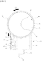
FIG. 1 is a plan view illustrating an internal structure by removing a cover from one exemplary embodiment of a negative pressure generating device according to the present invention. -
FIG. 2 is a plan view illustrating a state in which a rotating unit is removed from the exemplary embodiment illustrated inFIG. 1 . -
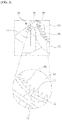
FIG. 3 is a perspective view enlarging major components of a rotating unit and a negative pressure changing unit which configure an exemplary embodiment of the present invention. -
FIG. 4 is a plan view illustrating an internal structure of a negative pressure cylinder which configures an exemplary embodiment of the present invention. -
- 10: External housing
- 11: Installation space
- 20: Static load elastic unit
- 21,23: First drum and Second drum
- 25: Steel strip
- 30: Rotating unit
- 35: Gear teeth
- 40: Interlocking assembly
- 43: Winder
- 45: Pulley
- 50: Negative pressure cylinder
- 55: Piston
- 58: Connecting unit
- W: Wire
- Hereinafter, some embodiments of the present invention will be described in detail with reference to the accompanying drawings. When reference numerals denote components in the drawings, even though the like parts are illustrated in different drawings, it should be noted that like reference numerals refer to the same parts. In describing the embodiments of the present invention, when it is determined that the detailed description of the known art related to the present invention may obscure the gist of the present invention, the detailed description thereof will be omitted.
- The present invention relates to a device for generating a negative pressure and an automatic negative pressure wound therapy device applying the same. The present invention may be used for various medical purposes such as general surgery, thoracic surgery, and neurosurgery as well as a negative pressure wound therapy device for improving blood flow. The negative pressure generating device according to the present invention may also be used for non-medical purpose.
- A basic frame of the present invention is formed by an
external housing 10. An installation space 11 is formed in theexternal housing 10 and is shielded by a cover. For reference, the cover is omitted to illustrate an internal structure. Theexternal housing 10 may be formed of a light material such as synthetic resin. Referring toFIG. 1 , an upper portion of theexternal housing 10 is formed to have a substantially circular shape and a lower portion is formed to have a rectangular shape, but the shape of theexternal housing 10 is not necessarily limited thereto. - A static load
elastic unit 20 is provided in the installation space 11 of theexternal housing 10. The static loadelastic unit 20 provides an elastic force having a predetermined magnitude to generate a constant negative pressure. In the present exemplary embodiment, the static loadelastic unit 20 is a constant torque spring configured by winding aflexible steel strip 25 around a drum. The static loadelastic unit 20 basically has a tendency to keep thesteel strip 25 wound around the drum. When thesteel strip 25 is installed to be unwound, the steel strip is gradually wound to operate arotating unit 30 and anegative pressure cylinder 50 which will be described below. That is, the static loadelastic unit 20 may also be considered as a spring motor. - In the present exemplary embodiment, the static load
elastic unit 20, as illustrated inFIG. 1 , may be configured by afirst drum 21 and asecond drum 23 which are rotatably installed and thesteel strip 25 wound around the first drum and the second drum. One end of thesteel strip 25 is connected to the rotatingunit 30 and the other end is connected to thefirst drum 21 to rotate therotating unit 30 while being wound by the elastic force. The static loadelastic unit 20 may not be necessarily a single spring motor, but may be a multiple spring motor including a plurality of drums and steel strips 25. - The static load
elastic unit 20 has a torque with a predetermined magnitude so that the static loadelastic unit 20 may rotate therotating unit 30 while being gradually wound. That is, as the winding degree of thesteel strip 25 is increased, the elastic force of the static loadelastic unit 20 is not reduced but an elastic force with a predetermined magnitude is provided so that, consequently, a constant negative pressure is generated. - The rotating
unit 30 is provided in the installation space 11. The rotatingunit 30 pulls apiston 55 in thenegative pressure cylinder 50 while rotating around arotary shaft 37 in the installation space 11. More specifically, the rotatingunit 30 rotates by thesteel strip 25 of the static loadelastic unit 20 and transmits the torque to thepiston 55 of thenegative pressure cylinder 50 so that thepiston 55 linearly moves to generate a negative pressure. - The rotating
unit 30 has a thin disk shape. Referring toFIG. 3 , a frame of the rotatingunit 30 is formed by arotary body 32 having a predetermined thickness. The end portion of thesteel strip 25 of the static loadelastic unit 20 is connected to therotary body 32 so that thesteel strip 25 may be wound or reversely unwound around an outer circumferential surface of therotary body 32 to some content. - A
gear plate 31 is provided above therotary body 32. Thegear plate 31 is coupled to therotary body 32 to rotate together and gearteeth 35 are provided on an outer circumferential surface thereof. The gear teeth of thegear plate 31 are interfered by the negativepressure changing unit 70 which will be described below to apply a constant pressure, which is periodically repeated, to the rotatingunit 30. Therefore, a force of thegear plate 31 that pulls thepiston 55 of thenegative pressure cylinder 50 is also changed at a predetermined interval and consequently, the negative pressure may vary. For reference, thegear plate 31 may be integrally formed with therotary body 32. - In the exemplary embodiment, the
gear teeth 35 formed on thegear plate 31 may be continuously and constantly formed around the outer circumferential surface of thegear plate 31. Therefore, the variable negative pressure is repeated at a predetermined interval. However, thegear teeth 35 may be discontinuously formed on thegear plate 31. For example, thegear teeth 35 are formed in a predetermined section of the outer circumferential surface of thegear plate 31, but thegear teeth 35 may be omitted in a predetermined section. Therefore, this pattern is repeated to increase the changing interval of the negative pressure. However, the negative pressure may vary by changing a pitch of thegear teeth 35. - In the meantime, a
rotary hole 33 is formed in the rotatingunit 30 and therotary shaft 37 is fitted to therotary hole 33 to serve as a rotation center of the rotatingunit 30. Therotary shaft 37 also serves as arotary shaft 37 of awinder 43 of aninterworking assembly 40 which will be described below. - In the exemplary embodiment, the rotating
unit 30 is not directly connected to thenegative pressure cylinder 50, but is connected to thenegative pressure cylinder 50 via theinterworking assembly 40. The interworkingassembly 40 is provided between therotating unit 30 and thenegative pressure cylinder 50 to connect to each other. The interworkingassembly 40 is connected to thepiston 55 of thenegative pressure cylinder 50 to pull thepiston 55 by the torque of the rotatingunit 30 and generate the negative pressure. - As illustrated in
FIG. 2 , the interworkingassembly 40 mainly includes awinder 43 and apulley 45. Thewinder 43 winds the wire W and rotates coaxially with therotary shaft 37 of the rotatingunit 30. One end of the wire W which is wound around thewinder 43 is connected to thewinder 43 so that when thewinder 43 rotates, the wire W is continuously wound and the other end is connected to the connectingunit 58 of thenegative pressure cylinder 50 via apulley 45 to pull thepiston 55. - The
winder 43 has a disk shape which rotates around therotary shaft 37 and thepulley 45 is installed to be adjacent to thewinder 43 and functions to support the wire W or change a movement path of the wire W. That is, thepulley 45 is considered as an idler pulley. However, thepulley 45 may be omitted. - In this case, when sizes of the rotating
unit 30 and theinterworking assembly 40 are compared, a diameter of the rotatingunit 30 is larger than thewinder 43 of the interworkingassembly 40. In the present exemplary embodiment, the diameter of the rotatingunit 30 is at least five times or larger than a diameter of thewinder 43. By doing this, an angle at which the rotatingunit 30 rotates by the static loadelastic unit 20 is reduced and a degree of pulling of the connectingunit 58 of thenegative pressure cylinder 50 while thewinder 43 rotates is reduced. By doing this, a length by which the connectingunit 58 of thenegative pressure cylinder 50 is pulled is reduced and the negative pressure may be slowly generated for a long time. For example, since the diameter of the rotatingunit 30 is very large, the rotatingunit 30 may be limited to make one rotation in total, that is, 360 degrees by the static loadelastic unit 20. Further, in this case, thewinder 43 which coaxially rotates with the rotatingunit 30 also rotates only at 360 degrees and during this process, the wire W wound on the outer surface of thewinder 43 is shortened by a length to wrap the outer surface of thewinder 43 once. As a result, the connectingunit 58 of thenegative pressure cylinder 50 connected to the wire W is also pulled by a length to wrap the outer surface of thewinder 43 once. - In the meantime, the
negative pressure cylinder 50 is connected to theinterworking assembly 40. Thenegative pressure cylinder 50 operates by the interworkingassembly 40 to generate a negative pressure therein. As illustrated inFIG. 4 , thenegative pressure cylinder 50 includes acylinder housing 51 which forms a frame and apiston 55 which is installed in thecylinder housing 51 to linearly move. The connectingunit 58 is connected to thepiston 55 and the connectingunit 58 is connected to the wire W of the interworkingassembly 40 described above, so that consequently, thepiston 55 is pulled by the interworkingassembly 40. - The
piston 55 lowers a pressure of internal spaces S1 and S2 while moving along the internal spaces S1 and S2 of thecylinder housing 51. Thepiston 55 divides the internal spaces S1 and S2 into a first space S1 which is a relatively upper portion and a second space S2 to suppress the movement of air therebetween. Even though not illustrated in the drawing, a sealing member having an elastic material such as silicon or rubber may be provided on the outer surface of thepiston 55. As thepiston 55 is upwardly pulled, the pressure is lowered so that the second space S2 divided by thepiston 55 generates the negative pressure. - A
negative pressure tube 60 is coupled to an inlet of thenegative pressure cylinder 50. Thenegative pressure tube 60 is coupled to the inlet of thenegative pressure cylinder 50 to connect the second space S2 of thenegative pressure cylinder 50 in which the negative pressure is generated to the outside. Therefore, the negative pressure may be provided. Desirably, thenegative pressure tube 60 is exchangeably coupled to thenegative pressure cylinder 50 so that when the negative pressure tube is contaminated, the user may exchange the negative pressure tube.Reference numeral 65 denotes an inlet of thenegative pressure tube 60. - The negative
pressure changing unit 70 is provided in the installation space 11. The negativepressure changing unit 70 interferes with the rotatingunit 30 to adjust the torque of the rotatingunit 30. More specifically, an interferingprotrusion 77 which controls the torque by selectively locking thegear teeth 35 provided on the outer circumferential surface of the rotatingunit 30 is provided to periodically generate interference while the rotatingunit 30 rotates. - As illustrated in
FIG. 3 , abracket 71 of the negativepressure changing unit 70 is installed and a fixedbody 75 is provided in thebracket 71. The fixedbody 75 is fixed to thebracket 71 and the interferingprotrusion 77 gets in and out from the fixedbody 75. The interferingprotrusion 77 is provided to be movable to an outer circumferential direction of the rotatingunit 30 and an elastic member (not illustrated) which elastically supports the interferingprotrusion 77 to the outer circumferential direction of the rotatingunit 30 is provided in the negativepressure changing unit 70. By doing this, the interferingprotrusion 77 moves to the outer circumferential direction of the rotatingunit 30 by an elastic force of the elastic member so that the interferingprotrusion 77 is continuously engaged with thegear teeth 35 of the rotatingunit 30 to control the torque of the rotatingunit 30. The elastic member may be omitted and the interferingprotrusion 77 may be formed of an elastic material. - In the above exemplary embodiment, the
gear teeth 35 is provided in the rotatingunit 30 and the interferingprotrusion 77 of the negativepressure changing unit 70 locks the gear teeth to control the torque. Unlikely, thegear teeth 35 of the rotatingunit 30 may be omitted and the rotatingunit 30 periodically causes the friction with the negativepressure changing unit 70 to control the torque. That is, the interferingprotrusion 77 of the negativepressure changing unit 70 is in contact with the outer circumferential surface of the rotatingunit 30 to cause friction, thereby controlling the torque. In this case, it may be configured such that the interferingprotrusion 77 periodically causes the friction with the rotatingunit 30 while the negativepressure changing unit 70 rotates. - Even though not illustrated in the drawings, an indicator may be installed in the
external housing 10. The indicator is connected to any one of the static loadelastic unit 20, thewinder 43 of the interlockingassembly 40, the wire W, and the connectingunit 58 which perform the rotating operation to rotate or linearly move to identify from the outside how much the present invention is operated. That is, the indicator may indicate a remaining amount of a total amount of negative pressure which may be generated by the negative pressure generating device according to the present invention. - Even though not illustrated in the drawings, a switch may be installed in the
external housing 10. The switch is a kind of a stopper and functions to selectively stop the operation of the present invention. For example, the switch locks one side of the rotatingunit 30 to stop the rotation of the rotatingunit 30. By doing this, before manipulating the switch, the rotatingunit 30 does not rotate so that the negative pressure is not generated. - Hereinafter, an operating process by the present invention will be described.
- First, the
steel strip 25 of the static loadelastic unit 20 is unfolded while overcoming the elastic force so that one end thereof is fixed to therotary body 32 of the rotatingunit 30. In this state, when the user manipulates the switch, the present invention operates. - For example, when the switch is turned on, the
steel strip 25 of the static loadelastic unit 20 is gradually wound around thefirst drum 21 of the static loadelastic unit 20 with a predetermined force. A winding direction of thesteel strip 25 is denoted by an arrow 1 ofFIG. 1 . As thesteel strip 25 is gradually wound, the rotatingunit 30 rotates in a direction of anarrow 2. - When the
rotating unit 30 rotates, thewinder 43 of the interlockingassembly 40 is wound coaxially with therotary shaft 37 of the rotatingunit 30. Thewinder 43 is wound in the direction of the arrow 3 ofFIG. 2 and in this process, the wire W is wound around thewinder 43. The winding direction of the wire W is represented by anarrow 4 ofFIG. 2 . - When the wire W is wound, the connecting
unit 58 of thenegative pressure cylinder 50 connected to the wire W also moves along the wire W and the connectingunit 58 pulls thepiston 55 in the direction of anarrow 5 ofFIG. 4 . Therefore, a volume of the first space S1 between the internal spaces S1 and S2 of thenegative pressure cylinder 50 is reduced and a volume of the second space S2 is increased so that the pressure of the second space S2 is reduced to generate a negative pressure. The negative pressure is provided to the outside by thenegative pressure tube 60. - In the meantime, during the process of rotating the
rotating unit 30, the negativepressure changing unit 70 periodically changes the torque of the rotatingunit 30 to adjust the negative pressure generated in thenegative pressure cylinder 50. More specifically, the interferingprotrusion 77 of the negativepressure changing unit 70 selectively locks thegear teeth 35 provided on the outer circumferential surface of the rotatingunit 30 to change the magnitude of the negative pressure while controlling the torque. - In this case, the interfering
protrusion 77 moves to the outer circumferential direction of the rotatingunit 30 by an elastic force of the elastic member so that the interferingprotrusion 77 is continuously engaged with thegear teeth 35 of the rotatingunit 30 to control the torque of the rotatingunit 30. However, the negative pressure may vary by changing a pitch of thegear teeth 35. - As described above, the
gear teeth 35 of the rotatingunit 30 is omitted and the rotatingunit 30 periodically causes friction with the negativepressure changing unit 70 to control the torque. In this case, the interferingprotrusion 77 of the negativepressure changing unit 70 is in contact with the outer circumferential surface of the rotatingunit 30 to cause friction, thereby controlling the torque. - The rotating
unit 30 gradually rotates by the static loadelastic unit 20 and the negative pressure is consistently generated from thenegative pressure cylinder 50 during this process. In this case, since the diameter of the rotatingunit 30 is larger than thewinder 43 of the interlockingassembly 40, a length of the connectingunit 58 of thenegative pressure cylinder 50 which is pulled is reduced and the negative pressure may be slowly generated for a long time. - In the meantime, when the negative pressure generating device described in the present exemplary embodiment is used as an automatic negative pressure wound therapy device having a pressure changing function, the negative pressure generating device may be used to be disposable, but may also be reused. For example, only components which are exposed to the outside or contaminated are exchanged and the remaining components may be reused.
- Further, the negative
pressure changing unit 70 which configures the exemplary embodiment of the present invention may be omitted. For example, when the pressure changing function is not necessary, the negativepressure changing unit 70 is not necessary too. Therefore, the negativepressure changing unit 70 may be omitted. In this case, the negativepressure changing unit 70 may be manufactured to be attachable to be selectively used. - It will be appreciated that various exemplary embodiments of the present invention have been described herein for purposes of illustration, and that various modifications, changes, and substitutions may be made by those skilled in the art without departing from the scope and spirit of the present invention. Accordingly, the exemplary embodiments disclosed herein are intended to not limit but describe the technical spirit of the present invention and the scope of the technical spirit of the present invention is not restricted by the exemplary embodiments. The protection scope of the present invention should be interpreted based on the following appended claims and it should be appreciated that all technical spirits included within a range equivalent thereto are included in the protection scope of the present invention.
Claims (11)
- A negative pressure generating device, comprising:a static load elastic unit which provides an elastic force having a predetermined magnitude;a rotating unit which is connected to the static load elastic unit to rotate by the static load elastic unit; anda negative pressure cylinder which is connected to the rotating unit and interworks with the rotation of the rotating unit to generate a negative pressure therein.
- The negative pressure generating device of claim 1, wherein the negative pressure cylinder includes:a cylinder housing;a piston which is linearly movably installed in the cylinder housing; anda connecting unit which connects the piston and the static load elastic unit.
- The negative pressure generating device of claim 2, wherein an interlocking assembly is provided between the rotating unit and the negative pressure cylinder to connect to each other and the interlocking assembly is connected to the piston of the negative pressure cylinder to generate the negative pressure while pulling the piston by a torque of the rotating unit.
- The negative pressure generating device of claim 3, wherein the interlocking assembly includes:a winder which winds a wire while rotating coaxially with the rotating unit; anda pulley which is installed to be adjacent to the winder and supports the wire or changes a movement path of the wire, andone end of the wire is connected to the wire to be continuously wound and the other end is connected to the connecting unit of the negative pressure cylinder via the pulley to pull the piston.
- The negative pressure generating device of claim 4, wherein a diameter of the rotating unit is larger than the winder of the interlocking assembly.
- The negative pressure generating device of claim 1, wherein the rotating unit includes a negative pressure changing unit which interferes with the rotating unit to adjust a torque of the rotating unit.
- The negative pressure generating device of claim 6, wherein in the negative pressure changing unit, an interfering protrusion which selectively locks gear teeth provided on an outer circumferential surface of the rotating unit to adjust a torque is provided to be movable to the outer circumferential surface of the rotating unit and the negative pressure changing unit includes an elastic member which elastically supports the interfering protrusion in the outer circumferential direction of the rotating unit.
- The negative pressure generating device of claim 7, wherein the gear teeth provided on the outer circumferential surface of the rotating unit is continuously or discontinuously provided along the outer circumferential surface of the rotating unit to vary a rotating speed of the rotating unit.
- The negative pressure generating device of claim 1, wherein a negative pressure tube which outwardly protrudes is exchangeably coupled to an inlet of the negative pressure cylinder.
- The negative pressure generating device of claim 1, wherein the static load elastic unit is a constant torque spring which is configured such that a steel strip is wound around a drum.
- An automatic negative pressure wound therapy device, comprising:an external housing; andthe negative pressure generating device of any one of claims 1 to 10 installed in the external housing.
Applications Claiming Priority (2)
| Application Number | Priority Date | Filing Date | Title |
|---|---|---|---|
| KR1020160148159A KR101942396B1 (en) | 2016-11-08 | 2016-11-08 | Apparatus for generating negative pressure and automatic negative pressure wound therapy for improvement of blood flow |
| PCT/KR2017/012584 WO2018088791A2 (en) | 2016-11-08 | 2017-11-08 | Negative pressure generator and automatic negative pressure wound treatment apparatus using same to have pressure change function |
Publications (3)
| Publication Number | Publication Date |
|---|---|
| EP3539578A2 true EP3539578A2 (en) | 2019-09-18 |
| EP3539578A4 EP3539578A4 (en) | 2020-06-03 |
| EP3539578B1 EP3539578B1 (en) | 2023-10-25 |
Family
ID=62110266
Family Applications (1)
| Application Number | Title | Priority Date | Filing Date |
|---|---|---|---|
| EP17870523.2A Active EP3539578B1 (en) | 2016-11-08 | 2017-11-08 | Negative pressure generator and automatic negative pressure wound treatment apparatus using same to have pressure change function |
Country Status (4)
| Country | Link |
|---|---|
| US (1) | US11185618B2 (en) |
| EP (1) | EP3539578B1 (en) |
| KR (1) | KR101942396B1 (en) |
| WO (1) | WO2018088791A2 (en) |
Family Cites Families (16)
| Publication number | Priority date | Publication date | Assignee | Title |
|---|---|---|---|---|
| US197311A (en) * | 1877-11-20 | Improvement in hydraulic elevators | ||
| US467054A (en) * | 1892-01-12 | Brake for children s carriages | ||
| US828624A (en) * | 1905-03-20 | 1906-08-14 | Dewitt Clinton Mcintire | Pumping apparatus. |
| US2270043A (en) * | 1939-02-13 | 1942-01-13 | Paper Patents Co | Compressed wadding roll |
| US2956511A (en) * | 1957-12-04 | 1960-10-18 | Morehead Enoch Watson | Water lifting device |
| US4230520A (en) * | 1978-08-14 | 1980-10-28 | Decca Limited | Automatic tape winding machine |
| KR200293046Y1 (en) * | 2002-08-02 | 2002-10-25 | 이영웅 | automatic milker |
| CN105833364A (en) * | 2006-10-17 | 2016-08-10 | 蓝天医疗集团有限公司 | Auxiliary powered negative pressure wound therapy apparatuses and methods |
| WO2009067711A2 (en) * | 2007-11-21 | 2009-05-28 | T.J. Smith & Nephew, Limited | Suction device and dressing |
| EP2252342B1 (en) * | 2008-02-14 | 2014-10-08 | Spiracur Inc. | Devices and methods for treatment of damaged tissue |
| US9039678B2 (en) | 2008-04-03 | 2015-05-26 | The Brigham And Women's Hospital, Inc | Micromechanical force devices for wound healing acceleration |
| EP2324868A1 (en) * | 2009-07-28 | 2011-05-25 | Koninklijke Philips Electronics N.V. | Flexible drive for breast pump |
| US8795246B2 (en) | 2010-08-10 | 2014-08-05 | Spiracur Inc. | Alarm system |
| KR101360194B1 (en) * | 2011-12-30 | 2014-02-12 | 주식회사 무한기업 | Medical Suction Unit |
| US20140163521A1 (en) * | 2012-12-12 | 2014-06-12 | Animas Corporation | Medical infusion pump mechanism |
| US9366077B2 (en) * | 2014-11-05 | 2016-06-14 | Chin-Fu Chen | Blind body positioning mechanism for non pull cord window blind and window blind using same |
-
2016
- 2016-11-08 KR KR1020160148159A patent/KR101942396B1/en not_active Expired - Fee Related
-
2017
- 2017-11-08 WO PCT/KR2017/012584 patent/WO2018088791A2/en not_active Ceased
- 2017-11-08 US US16/348,191 patent/US11185618B2/en active Active
- 2017-11-08 EP EP17870523.2A patent/EP3539578B1/en active Active
Also Published As
| Publication number | Publication date |
|---|---|
| KR20180051178A (en) | 2018-05-16 |
| WO2018088791A3 (en) | 2018-08-09 |
| US11185618B2 (en) | 2021-11-30 |
| WO2018088791A2 (en) | 2018-05-17 |
| EP3539578A4 (en) | 2020-06-03 |
| US20190275215A1 (en) | 2019-09-12 |
| KR101942396B1 (en) | 2019-01-25 |
| EP3539578B1 (en) | 2023-10-25 |
Similar Documents
| Publication | Publication Date | Title |
|---|---|---|
| US20220387697A1 (en) | Self contained wound dressing with micropump | |
| CN110464887B (en) | Controlled negative pressure device and alarm mechanism | |
| US8317774B2 (en) | Suction system | |
| JP2015513424A5 (en) | ||
| CN104023762A (en) | Wound care device that uses negative pressure to treat wounds | |
| RU2015135185A (en) | TEAM SYRINGES WITH A LOCKING MECHANISM AND RELATED DEVICES AND METHODS | |
| JP2011525383A (en) | Tissue enclosure | |
| KR101360194B1 (en) | Medical Suction Unit | |
| EP3539578B1 (en) | Negative pressure generator and automatic negative pressure wound treatment apparatus using same to have pressure change function | |
| AU2025223782A1 (en) | Medical tube clearance device | |
| KR20170111610A (en) | Suction Pump Capable of Precise Manipulating Motion of Catheter | |
| CN109998890A (en) | Hand-held device with hollow piston | |
| CN210631260U (en) | A handheld endoscopic hemostatic device for cardiothoracic surgery | |
| EP4138944B1 (en) | Dual mode negative pressure source operation for provision of negative pressure wound therapy | |
| CN110251132A (en) | A kind of rotating device for nuclear magnetic resonance | |
| KR102354454B1 (en) | Film membrane coating apparatus for skin | |
| CN115089822A (en) | A rapid hemostatic device | |
| CN208611415U (en) | Drainage system | |
| EP4192540B1 (en) | Negative pressure medical device | |
| CN110464420B (en) | Interventional devices for cardiovascular therapy | |
| CN114322505A (en) | Disinfection drying device for surgical knife | |
| JP2012045090A (en) | Scalp care device | |
| HK1156837A (en) | Scalp care device | |
| RU2017104064A (en) | Hand-held portable device for winding boxing bandages into a roll | |
| RU2013138284A (en) | PORTABLE MEDICAL DEVICE |
Legal Events
| Date | Code | Title | Description |
|---|---|---|---|
| STAA | Information on the status of an ep patent application or granted ep patent |
Free format text: STATUS: THE INTERNATIONAL PUBLICATION HAS BEEN MADE |
|
| PUAI | Public reference made under article 153(3) epc to a published international application that has entered the european phase |
Free format text: ORIGINAL CODE: 0009012 |
|
| STAA | Information on the status of an ep patent application or granted ep patent |
Free format text: STATUS: REQUEST FOR EXAMINATION WAS MADE |
|
| 17P | Request for examination filed |
Effective date: 20190412 |
|
| AK | Designated contracting states |
Kind code of ref document: A2 Designated state(s): AL AT BE BG CH CY CZ DE DK EE ES FI FR GB GR HR HU IE IS IT LI LT LU LV MC MK MT NL NO PL PT RO RS SE SI SK SM TR |
|
| AX | Request for extension of the european patent |
Extension state: BA ME |
|
| DAV | Request for validation of the european patent (deleted) | ||
| DAX | Request for extension of the european patent (deleted) | ||
| A4 | Supplementary search report drawn up and despatched |
Effective date: 20200508 |
|
| RIC1 | Information provided on ipc code assigned before grant |
Ipc: A61M 1/00 20060101AFI20200501BHEP |
|
| GRAP | Despatch of communication of intention to grant a patent |
Free format text: ORIGINAL CODE: EPIDOSNIGR1 |
|
| STAA | Information on the status of an ep patent application or granted ep patent |
Free format text: STATUS: GRANT OF PATENT IS INTENDED |
|
| INTG | Intention to grant announced |
Effective date: 20230504 |
|
| GRAS | Grant fee paid |
Free format text: ORIGINAL CODE: EPIDOSNIGR3 |
|
| GRAA | (expected) grant |
Free format text: ORIGINAL CODE: 0009210 |
|
| STAA | Information on the status of an ep patent application or granted ep patent |
Free format text: STATUS: THE PATENT HAS BEEN GRANTED |
|
| AK | Designated contracting states |
Kind code of ref document: B1 Designated state(s): AL AT BE BG CH CY CZ DE DK EE ES FI FR GB GR HR HU IE IS IT LI LT LU LV MC MK MT NL NO PL PT RO RS SE SI SK SM TR |
|
| REG | Reference to a national code |
Ref country code: GB Ref legal event code: FG4D |
|
| REG | Reference to a national code |
Ref country code: CH Ref legal event code: EP |
|
| REG | Reference to a national code |
Ref country code: DE Ref legal event code: R096 Ref document number: 602017075817 Country of ref document: DE |
|
| REG | Reference to a national code |
Ref country code: IE Ref legal event code: FG4D |
|
| PGFP | Annual fee paid to national office [announced via postgrant information from national office to epo] |
Ref country code: GB Payment date: 20231220 Year of fee payment: 7 |
|
| PGFP | Annual fee paid to national office [announced via postgrant information from national office to epo] |
Ref country code: FR Payment date: 20231211 Year of fee payment: 7 |
|
| REG | Reference to a national code |
Ref country code: LT Ref legal event code: MG9D |
|
| REG | Reference to a national code |
Ref country code: NL Ref legal event code: MP Effective date: 20231025 |
|
| REG | Reference to a national code |
Ref country code: AT Ref legal event code: MK05 Ref document number: 1624019 Country of ref document: AT Kind code of ref document: T Effective date: 20231025 |
|
| PG25 | Lapsed in a contracting state [announced via postgrant information from national office to epo] |
Ref country code: NL Free format text: LAPSE BECAUSE OF FAILURE TO SUBMIT A TRANSLATION OF THE DESCRIPTION OR TO PAY THE FEE WITHIN THE PRESCRIBED TIME-LIMIT Effective date: 20231025 |
|
| PG25 | Lapsed in a contracting state [announced via postgrant information from national office to epo] |
Ref country code: GR Free format text: LAPSE BECAUSE OF FAILURE TO SUBMIT A TRANSLATION OF THE DESCRIPTION OR TO PAY THE FEE WITHIN THE PRESCRIBED TIME-LIMIT Effective date: 20240126 |
|
| PG25 | Lapsed in a contracting state [announced via postgrant information from national office to epo] |
Ref country code: IS Free format text: LAPSE BECAUSE OF FAILURE TO SUBMIT A TRANSLATION OF THE DESCRIPTION OR TO PAY THE FEE WITHIN THE PRESCRIBED TIME-LIMIT Effective date: 20240225 |
|
| PG25 | Lapsed in a contracting state [announced via postgrant information from national office to epo] |
Ref country code: LT Free format text: LAPSE BECAUSE OF FAILURE TO SUBMIT A TRANSLATION OF THE DESCRIPTION OR TO PAY THE FEE WITHIN THE PRESCRIBED TIME-LIMIT Effective date: 20231025 |
|
| PG25 | Lapsed in a contracting state [announced via postgrant information from national office to epo] |
Ref country code: AT Free format text: LAPSE BECAUSE OF FAILURE TO SUBMIT A TRANSLATION OF THE DESCRIPTION OR TO PAY THE FEE WITHIN THE PRESCRIBED TIME-LIMIT Effective date: 20231025 |
|
| PG25 | Lapsed in a contracting state [announced via postgrant information from national office to epo] |
Ref country code: ES Free format text: LAPSE BECAUSE OF FAILURE TO SUBMIT A TRANSLATION OF THE DESCRIPTION OR TO PAY THE FEE WITHIN THE PRESCRIBED TIME-LIMIT Effective date: 20231025 |
|
| PG25 | Lapsed in a contracting state [announced via postgrant information from national office to epo] |
Ref country code: LT Free format text: LAPSE BECAUSE OF FAILURE TO SUBMIT A TRANSLATION OF THE DESCRIPTION OR TO PAY THE FEE WITHIN THE PRESCRIBED TIME-LIMIT Effective date: 20231025 Ref country code: IS Free format text: LAPSE BECAUSE OF FAILURE TO SUBMIT A TRANSLATION OF THE DESCRIPTION OR TO PAY THE FEE WITHIN THE PRESCRIBED TIME-LIMIT Effective date: 20240225 Ref country code: GR Free format text: LAPSE BECAUSE OF FAILURE TO SUBMIT A TRANSLATION OF THE DESCRIPTION OR TO PAY THE FEE WITHIN THE PRESCRIBED TIME-LIMIT Effective date: 20240126 Ref country code: ES Free format text: LAPSE BECAUSE OF FAILURE TO SUBMIT A TRANSLATION OF THE DESCRIPTION OR TO PAY THE FEE WITHIN THE PRESCRIBED TIME-LIMIT Effective date: 20231025 Ref country code: BG Free format text: LAPSE BECAUSE OF FAILURE TO SUBMIT A TRANSLATION OF THE DESCRIPTION OR TO PAY THE FEE WITHIN THE PRESCRIBED TIME-LIMIT Effective date: 20240125 Ref country code: AT Free format text: LAPSE BECAUSE OF FAILURE TO SUBMIT A TRANSLATION OF THE DESCRIPTION OR TO PAY THE FEE WITHIN THE PRESCRIBED TIME-LIMIT Effective date: 20231025 Ref country code: PT Free format text: LAPSE BECAUSE OF FAILURE TO SUBMIT A TRANSLATION OF THE DESCRIPTION OR TO PAY THE FEE WITHIN THE PRESCRIBED TIME-LIMIT Effective date: 20240226 |
|
| PGFP | Annual fee paid to national office [announced via postgrant information from national office to epo] |
Ref country code: DE Payment date: 20231215 Year of fee payment: 7 |
|
| PG25 | Lapsed in a contracting state [announced via postgrant information from national office to epo] |
Ref country code: SE Free format text: LAPSE BECAUSE OF FAILURE TO SUBMIT A TRANSLATION OF THE DESCRIPTION OR TO PAY THE FEE WITHIN THE PRESCRIBED TIME-LIMIT Effective date: 20231025 Ref country code: RS Free format text: LAPSE BECAUSE OF FAILURE TO SUBMIT A TRANSLATION OF THE DESCRIPTION OR TO PAY THE FEE WITHIN THE PRESCRIBED TIME-LIMIT Effective date: 20231025 Ref country code: PL Free format text: LAPSE BECAUSE OF FAILURE TO SUBMIT A TRANSLATION OF THE DESCRIPTION OR TO PAY THE FEE WITHIN THE PRESCRIBED TIME-LIMIT Effective date: 20231025 Ref country code: NO Free format text: LAPSE BECAUSE OF FAILURE TO SUBMIT A TRANSLATION OF THE DESCRIPTION OR TO PAY THE FEE WITHIN THE PRESCRIBED TIME-LIMIT Effective date: 20240125 Ref country code: LV Free format text: LAPSE BECAUSE OF FAILURE TO SUBMIT A TRANSLATION OF THE DESCRIPTION OR TO PAY THE FEE WITHIN THE PRESCRIBED TIME-LIMIT Effective date: 20231025 Ref country code: HR Free format text: LAPSE BECAUSE OF FAILURE TO SUBMIT A TRANSLATION OF THE DESCRIPTION OR TO PAY THE FEE WITHIN THE PRESCRIBED TIME-LIMIT Effective date: 20231025 |
|
| REG | Reference to a national code |
Ref country code: CH Ref legal event code: PL |
|
| PG25 | Lapsed in a contracting state [announced via postgrant information from national office to epo] |
Ref country code: DK Free format text: LAPSE BECAUSE OF FAILURE TO SUBMIT A TRANSLATION OF THE DESCRIPTION OR TO PAY THE FEE WITHIN THE PRESCRIBED TIME-LIMIT Effective date: 20231025 |
|
| PG25 | Lapsed in a contracting state [announced via postgrant information from national office to epo] |
Ref country code: LU Free format text: LAPSE BECAUSE OF NON-PAYMENT OF DUE FEES Effective date: 20231108 |
|
| PG25 | Lapsed in a contracting state [announced via postgrant information from national office to epo] |
Ref country code: CH Free format text: LAPSE BECAUSE OF NON-PAYMENT OF DUE FEES Effective date: 20231130 |
|
| PG25 | Lapsed in a contracting state [announced via postgrant information from national office to epo] |
Ref country code: CZ Free format text: LAPSE BECAUSE OF FAILURE TO SUBMIT A TRANSLATION OF THE DESCRIPTION OR TO PAY THE FEE WITHIN THE PRESCRIBED TIME-LIMIT Effective date: 20231025 |
|
| REG | Reference to a national code |
Ref country code: DE Ref legal event code: R097 Ref document number: 602017075817 Country of ref document: DE |
|
| PG25 | Lapsed in a contracting state [announced via postgrant information from national office to epo] |
Ref country code: SK Free format text: LAPSE BECAUSE OF FAILURE TO SUBMIT A TRANSLATION OF THE DESCRIPTION OR TO PAY THE FEE WITHIN THE PRESCRIBED TIME-LIMIT Effective date: 20231025 |
|
| PG25 | Lapsed in a contracting state [announced via postgrant information from national office to epo] |
Ref country code: SM Free format text: LAPSE BECAUSE OF FAILURE TO SUBMIT A TRANSLATION OF THE DESCRIPTION OR TO PAY THE FEE WITHIN THE PRESCRIBED TIME-LIMIT Effective date: 20231025 Ref country code: SK Free format text: LAPSE BECAUSE OF FAILURE TO SUBMIT A TRANSLATION OF THE DESCRIPTION OR TO PAY THE FEE WITHIN THE PRESCRIBED TIME-LIMIT Effective date: 20231025 Ref country code: RO Free format text: LAPSE BECAUSE OF FAILURE TO SUBMIT A TRANSLATION OF THE DESCRIPTION OR TO PAY THE FEE WITHIN THE PRESCRIBED TIME-LIMIT Effective date: 20231025 Ref country code: LU Free format text: LAPSE BECAUSE OF NON-PAYMENT OF DUE FEES Effective date: 20231108 Ref country code: IT Free format text: LAPSE BECAUSE OF FAILURE TO SUBMIT A TRANSLATION OF THE DESCRIPTION OR TO PAY THE FEE WITHIN THE PRESCRIBED TIME-LIMIT Effective date: 20231025 Ref country code: EE Free format text: LAPSE BECAUSE OF FAILURE TO SUBMIT A TRANSLATION OF THE DESCRIPTION OR TO PAY THE FEE WITHIN THE PRESCRIBED TIME-LIMIT Effective date: 20231025 Ref country code: DK Free format text: LAPSE BECAUSE OF FAILURE TO SUBMIT A TRANSLATION OF THE DESCRIPTION OR TO PAY THE FEE WITHIN THE PRESCRIBED TIME-LIMIT Effective date: 20231025 Ref country code: CZ Free format text: LAPSE BECAUSE OF FAILURE TO SUBMIT A TRANSLATION OF THE DESCRIPTION OR TO PAY THE FEE WITHIN THE PRESCRIBED TIME-LIMIT Effective date: 20231025 Ref country code: CH Free format text: LAPSE BECAUSE OF NON-PAYMENT OF DUE FEES Effective date: 20231130 |
|
| REG | Reference to a national code |
Ref country code: BE Ref legal event code: MM Effective date: 20231130 |
|
| PG25 | Lapsed in a contracting state [announced via postgrant information from national office to epo] |
Ref country code: MC Free format text: LAPSE BECAUSE OF FAILURE TO SUBMIT A TRANSLATION OF THE DESCRIPTION OR TO PAY THE FEE WITHIN THE PRESCRIBED TIME-LIMIT Effective date: 20231025 |
|
| PG25 | Lapsed in a contracting state [announced via postgrant information from national office to epo] |
Ref country code: MC Free format text: LAPSE BECAUSE OF FAILURE TO SUBMIT A TRANSLATION OF THE DESCRIPTION OR TO PAY THE FEE WITHIN THE PRESCRIBED TIME-LIMIT Effective date: 20231025 |
|
| PLBE | No opposition filed within time limit |
Free format text: ORIGINAL CODE: 0009261 |
|
| STAA | Information on the status of an ep patent application or granted ep patent |
Free format text: STATUS: NO OPPOSITION FILED WITHIN TIME LIMIT |
|
| REG | Reference to a national code |
Ref country code: IE Ref legal event code: MM4A |
|
| 26N | No opposition filed |
Effective date: 20240726 |
|
| PG25 | Lapsed in a contracting state [announced via postgrant information from national office to epo] |
Ref country code: IE Free format text: LAPSE BECAUSE OF NON-PAYMENT OF DUE FEES Effective date: 20231108 |
|
| PG25 | Lapsed in a contracting state [announced via postgrant information from national office to epo] |
Ref country code: BE Free format text: LAPSE BECAUSE OF NON-PAYMENT OF DUE FEES Effective date: 20231130 |
|
| PG25 | Lapsed in a contracting state [announced via postgrant information from national office to epo] |
Ref country code: SI Free format text: LAPSE BECAUSE OF FAILURE TO SUBMIT A TRANSLATION OF THE DESCRIPTION OR TO PAY THE FEE WITHIN THE PRESCRIBED TIME-LIMIT Effective date: 20231025 |
|
| PG25 | Lapsed in a contracting state [announced via postgrant information from national office to epo] |
Ref country code: SI Free format text: LAPSE BECAUSE OF FAILURE TO SUBMIT A TRANSLATION OF THE DESCRIPTION OR TO PAY THE FEE WITHIN THE PRESCRIBED TIME-LIMIT Effective date: 20231025 Ref country code: IE Free format text: LAPSE BECAUSE OF NON-PAYMENT OF DUE FEES Effective date: 20231108 Ref country code: BE Free format text: LAPSE BECAUSE OF NON-PAYMENT OF DUE FEES Effective date: 20231130 |
|
| REG | Reference to a national code |
Ref country code: DE Ref legal event code: R119 Ref document number: 602017075817 Country of ref document: DE |
|
| PG25 | Lapsed in a contracting state [announced via postgrant information from national office to epo] |
Ref country code: FI Free format text: LAPSE BECAUSE OF FAILURE TO SUBMIT A TRANSLATION OF THE DESCRIPTION OR TO PAY THE FEE WITHIN THE PRESCRIBED TIME-LIMIT Effective date: 20231025 |
|
| GBPC | Gb: european patent ceased through non-payment of renewal fee |
Effective date: 20241108 |
|
| PG25 | Lapsed in a contracting state [announced via postgrant information from national office to epo] |
Ref country code: CY Free format text: LAPSE BECAUSE OF FAILURE TO SUBMIT A TRANSLATION OF THE DESCRIPTION OR TO PAY THE FEE WITHIN THE PRESCRIBED TIME-LIMIT; INVALID AB INITIO Effective date: 20171108 |
|
| PG25 | Lapsed in a contracting state [announced via postgrant information from national office to epo] |
Ref country code: HU Free format text: LAPSE BECAUSE OF FAILURE TO SUBMIT A TRANSLATION OF THE DESCRIPTION OR TO PAY THE FEE WITHIN THE PRESCRIBED TIME-LIMIT; INVALID AB INITIO Effective date: 20171108 |
|
| PG25 | Lapsed in a contracting state [announced via postgrant information from national office to epo] |
Ref country code: DE Free format text: LAPSE BECAUSE OF NON-PAYMENT OF DUE FEES Effective date: 20250603 |
|
| PG25 | Lapsed in a contracting state [announced via postgrant information from national office to epo] |
Ref country code: GB Free format text: LAPSE BECAUSE OF NON-PAYMENT OF DUE FEES Effective date: 20241108 |
|
| PG25 | Lapsed in a contracting state [announced via postgrant information from national office to epo] |
Ref country code: FR Free format text: LAPSE BECAUSE OF NON-PAYMENT OF DUE FEES Effective date: 20241130 |
|
| PG25 | Lapsed in a contracting state [announced via postgrant information from national office to epo] |
Ref country code: TR Free format text: LAPSE BECAUSE OF FAILURE TO SUBMIT A TRANSLATION OF THE DESCRIPTION OR TO PAY THE FEE WITHIN THE PRESCRIBED TIME-LIMIT Effective date: 20231025 |