EP3539490A1 - Optical trocar assembly - Google Patents
Optical trocar assembly Download PDFInfo
- Publication number
- EP3539490A1 EP3539490A1 EP19162107.7A EP19162107A EP3539490A1 EP 3539490 A1 EP3539490 A1 EP 3539490A1 EP 19162107 A EP19162107 A EP 19162107A EP 3539490 A1 EP3539490 A1 EP 3539490A1
- Authority
- EP
- European Patent Office
- Prior art keywords
- retention member
- obturator
- sections
- main body
- section
- Prior art date
- Legal status (The legal status is an assumption and is not a legal conclusion. Google has not performed a legal analysis and makes no representation as to the accuracy of the status listed.)
- Granted
Links
Images



Classifications
-
- A—HUMAN NECESSITIES
- A61—MEDICAL OR VETERINARY SCIENCE; HYGIENE
- A61B—DIAGNOSIS; SURGERY; IDENTIFICATION
- A61B17/00—Surgical instruments, devices or methods
- A61B17/34—Trocars; Puncturing needles
- A61B17/3417—Details of tips or shafts, e.g. grooves, expandable, bendable; Multiple coaxial sliding cannulas, e.g. for dilating
-
- A—HUMAN NECESSITIES
- A61—MEDICAL OR VETERINARY SCIENCE; HYGIENE
- A61B—DIAGNOSIS; SURGERY; IDENTIFICATION
- A61B1/00—Instruments for performing medical examinations of the interior of cavities or tubes of the body by visual or photographical inspection, e.g. endoscopes; Illuminating arrangements therefor
- A61B1/32—Devices for opening or enlarging the visual field, e.g. of a tube of the body
-
- A—HUMAN NECESSITIES
- A61—MEDICAL OR VETERINARY SCIENCE; HYGIENE
- A61B—DIAGNOSIS; SURGERY; IDENTIFICATION
- A61B1/00—Instruments for performing medical examinations of the interior of cavities or tubes of the body by visual or photographical inspection, e.g. endoscopes; Illuminating arrangements therefor
- A61B1/313—Instruments for performing medical examinations of the interior of cavities or tubes of the body by visual or photographical inspection, e.g. endoscopes; Illuminating arrangements therefor for introducing through surgical openings, e.g. laparoscopes
- A61B1/3132—Instruments for performing medical examinations of the interior of cavities or tubes of the body by visual or photographical inspection, e.g. endoscopes; Illuminating arrangements therefor for introducing through surgical openings, e.g. laparoscopes for laparoscopy
-
- A—HUMAN NECESSITIES
- A61—MEDICAL OR VETERINARY SCIENCE; HYGIENE
- A61B—DIAGNOSIS; SURGERY; IDENTIFICATION
- A61B17/00—Surgical instruments, devices or methods
- A61B17/02—Surgical instruments, devices or methods for holding wounds open, e.g. retractors; Tractors
- A61B17/0218—Surgical instruments, devices or methods for holding wounds open, e.g. retractors; Tractors for minimally invasive surgery
-
- A—HUMAN NECESSITIES
- A61—MEDICAL OR VETERINARY SCIENCE; HYGIENE
- A61B—DIAGNOSIS; SURGERY; IDENTIFICATION
- A61B17/00—Surgical instruments, devices or methods
- A61B17/34—Trocars; Puncturing needles
- A61B17/3417—Details of tips or shafts, e.g. grooves, expandable, bendable; Multiple coaxial sliding cannulas, e.g. for dilating
- A61B17/3421—Cannulas
- A61B17/3423—Access ports, e.g. toroid shape introducers for instruments or hands
-
- A—HUMAN NECESSITIES
- A61—MEDICAL OR VETERINARY SCIENCE; HYGIENE
- A61B—DIAGNOSIS; SURGERY; IDENTIFICATION
- A61B17/00—Surgical instruments, devices or methods
- A61B2017/00831—Material properties
- A61B2017/00902—Material properties transparent or translucent
- A61B2017/00907—Material properties transparent or translucent for light
-
- A—HUMAN NECESSITIES
- A61—MEDICAL OR VETERINARY SCIENCE; HYGIENE
- A61B—DIAGNOSIS; SURGERY; IDENTIFICATION
- A61B17/00—Surgical instruments, devices or methods
- A61B17/32—Surgical cutting instruments
- A61B2017/320044—Blunt dissectors
-
- A—HUMAN NECESSITIES
- A61—MEDICAL OR VETERINARY SCIENCE; HYGIENE
- A61B—DIAGNOSIS; SURGERY; IDENTIFICATION
- A61B17/00—Surgical instruments, devices or methods
- A61B17/34—Trocars; Puncturing needles
- A61B17/3417—Details of tips or shafts, e.g. grooves, expandable, bendable; Multiple coaxial sliding cannulas, e.g. for dilating
- A61B2017/3454—Details of tips
-
- A—HUMAN NECESSITIES
- A61—MEDICAL OR VETERINARY SCIENCE; HYGIENE
- A61B—DIAGNOSIS; SURGERY; IDENTIFICATION
- A61B17/00—Surgical instruments, devices or methods
- A61B17/34—Trocars; Puncturing needles
- A61B2017/347—Locking means, e.g. for locking instrument in cannula
-
- A—HUMAN NECESSITIES
- A61—MEDICAL OR VETERINARY SCIENCE; HYGIENE
- A61B—DIAGNOSIS; SURGERY; IDENTIFICATION
- A61B90/00—Instruments, implements or accessories specially adapted for surgery or diagnosis and not covered by any of the groups A61B1/00 - A61B50/00, e.g. for luxation treatment or for protecting wound edges
- A61B90/36—Image-producing devices or illumination devices not otherwise provided for
- A61B90/361—Image-producing devices, e.g. surgical cameras
Definitions
- the present disclosure relates to a trocar assembly for use in minimally invasive surgical procedures, such as endoscopic or laparoscopic type procedures.
- Minimally invasive procedures are continually increasing in number and variation. Forming a relatively small diameter temporary pathway to the surgical site is a key feature of most minimally invasive surgical procedures.
- the most common method of providing such a pathway is by inserting a trocar assembly through the skin. In many procedures, the trocar assembly is inserted into an insufflated body cavity of a patient. In such procedures, trocar assemblies with seal mechanisms are utilized to provide the necessary pathway to the surgical site while minimizing leakage of insufflation gases.
- Trocar assemblies typically include an obturator and a cannula.
- the cannula having the obturator inserted therethrough, is directed through the skin to access a body cavity. Once the body cavity is accessed, laparoscopic or arthroscopic surgery and endoscopic procedures may be performed. With the cannula providing access to the body cavity, a surgical instrument (e.g., an endoscope or a laparoscope) may be guided into the body cavity through the cannula.
- a surgical instrument e.g., an endoscope or a laparoscope
- an obturator assembly in an aspect of the present disclosure, includes an obturator housing defining a cavity therein, an obturator shaft extending distally from the housing, and a retention member disposed within the cavity of the obturator housing.
- the retention member has a main body and a plurality of first sections formed in the main body.
- the main body has a first thickness and defines an opening dimensioned for receipt of a surgical instrument.
- the first sections are circumferentially disposed about the opening and have a second thickness that is less than the first thickness of the main body to facilitate flexing of the retention member during insertion of a surgical instrument into the opening.
- each of the first sections may extend radially outward from the opening.
- each of the first sections may extend from an inner peripheral surface of the main body of the retention member radially outward toward an outer peripheral surface of the main body of the retention member.
- each of the first sections may have an outer edge disposed inwardly of the outer peripheral surface.
- each of the first sections may have an outer edge coincident with the outer peripheral surface.
- each of the first sections may include a bottom surface, and a transition surface extending transversely between the bottom surface and one of an upper surface or a lower surface of the main body of the retention member.
- one or more of the first sections has a triangular configuration or a squared configuration.
- each of the first sections may be a depression formed in an upper surface or a lower surface of the main body of the retention member.
- the upper and lower surfaces of the main body of the retention member may be planar.
- the retention member may have a circular configuration.
- the opening of the retention member may be aligned with a central longitudinal axis defined by the obturator shaft.
- the retention member may be fabricated from a unitary piece of elastic material.
- the elastic material may be rubber and/or silicone.
- an optical trocar system in another aspect of the present disclosure, includes the obturator assembly and a cannula assembly configured to receive the obturator shaft of the obturator assembly therein.
- optical trocar system that provides access to a body cavity through an anatomical, e.g., abdominal, wall.
- anatomical e.g., abdominal, wall.
- optical trocar system may be used herein synonymously with the term visual obturator system.
- the optical trocar system of the present disclosure in accordance with various embodiments thereof, includes a retention member designed to stabilize a surgical instrument
- the retention member may be constructed from a unitary piece of elastomeric material and have a plurality of reduced-thickness sections disposed around a central opening thereof.
- the reduced-thickness sections allow for the retention member to flex upon receipt of a surgical instrument through the central opening.
- Disposed between the reduced-thickness sections are thicker sections that assist in stabilizing the surgical instrument within the central opening by inhibiting rotational movement and axial motion thereof during use.
- an optical trocar e.g., visual obturator, system or assembly 10 in accordance with an embodiment of the present disclosure.
- the visual obturator system 10 is intended for separating tissue planes in an endoscopic, e.g., laparoscopic, surgical procedure, and, is particularly suitable for the blunt dissection of the abdominal lining during a surgical procedure.
- the visual obturator system 10 is adapted to receive a surgical instrument, such as, for example, an endoscope, to permit viewing of tissue during the insertion and advancement of the visual obturator system 10 toward the operative site.
- the visual obturator system 10 generally includes an obturator assembly 11 and a cannula assembly 30 which at least partially receives the obturator assembly 11.
- the cannula assembly 30 of the visual obturator system 10 includes a clear elongated portion 32, defining a longitudinal axis "B-B,” and a head 34 monolithically formed with or connected to a proximal end portion of the elongated portion 32.
- the obturator assembly 11 of the visual obturator system 10 includes an obturator housing assembly 12 disposed in mechanical cooperation with an elongated obturator shaft 14 of the obturator assembly 11.
- the obturator housing assembly 12 includes an outer housing 12a, and an inner housing 12b supported on a proximal end portion of the elongated obturator shaft 14.
- the outer housing 12a may be constructed from two half-sections joined to one another.
- the outer housing 12a defines a cavity 16 therein in which the inner housing 12b is situated.
- the inner housing 12b defines a central passageway 18 extending longitudinally therethrough that is coaxial with a longitudinal axis "A-A" defined by the elongated obturator shaft 14.
- the elongated obturator shaft 14 extends distally from the obturator housing assembly 12 and may be rigid, e.g., metal.
- the elongated obturator shaft 14 may be attached, e.g., by over molding thereto, at its proximal end portion to the obturator housing assembly 12 and at its distal end portion to an optical member 20.
- the optical member 20 may be fabricated from a polymeric material, e.g., LEXAN, and is transparent, or at least semi-transparent, to permit passage of light rays. During assembly, the optical member 20 may be over-molded onto the distal end portion of the metal obturator shaft 14 to connect the components.
- the optical member 20 defines an internal chamfered or sloped surface (not explicitly shown) which is obliquely arranged relative to the longitudinal axis A-A.
- the chamfered surface of the optical member 20 is directly engaged by the outermost periphery of a distal end of an endoscope (not shown), such that light transmitted from regions of the endoscope travel radially within the outer periphery across an air gap prior to being received by the chamfered or sloped surface of the optical member 20.
- the optical member 20 permits the passage of light rays to enable viewing (by the endoscope) of tissue adjacent the optical member 20 during the insertion and/or advancement of the visual obturator system 10 through the tissue.
- the obturator assembly 11 further includes a retention member 100 disposed between the outer and inner housings 12a, 12b of the obturator housing assembly 12 and within the cavity 16 ( FIG. 1 ) of the obturator housing assembly 12.
- the retention member 100 includes a main body 101 that defines a central opening 102 coaxially aligned with each of the passageway 18 ( FIG. 1 ) of the inner housing 12b, the longitudinal axis A-A of the elongated obturator shaft 14, and the longitudinal axis B-B of the elongated portion 32 of the cannula assembly 30.
- the central opening 102 is dimensioned to receive a surgical instrument therethrough.
- the retention member 100 is constructed of a unitary piece of elastomeric material, such as an elastomer (e.g., rubber or silicone), and is adapted to engage an outer surface of a surgical instrument to assist in retaining the relative positioning of the surgical instrument within the optical trocar system 10.
- an elastomer e.g., rubber or silicone
- the retention member 100 may have a generally planar, disc-shaped configuration. In some embodiments, the retention member 100 may assume any suitable configuration such as squared or triangular.
- the main body 101 of the retention member 100 has an upper surface 104, a lower surface 106, an outer peripheral surface 108, and an inner peripheral surface 110 that defines the central opening 102.
- the main body 101 defines a first thickness between the upper and lower surfaces 104, 106 thereof.
- the retention member 100 further includes a plurality of first sections 112 formed in the main body 101 of the retention member 100.
- the first sections are circumferentially disposed about the opening 102 in the main body 101 of the retention member 100.
- the first sections 112 may be equally circumferentially spaced from one another about the opening 102 or unevenly circumferentially spaced about the opening 102.
- the first sections 112 may be depressions formed in the upper surface 104 of the main body 101 of the retention member 100, such that the first sections 112 have a reduced thickness relative to the main body 101 of the retention member 100.
- the first sections 112 may have a reduced thickness relative to the entire main body 101 of the retention member 100 or only portions thereof. In embodiments, the first sections or depressions 112 may be formed in one or both of the upper and lower surfaces 104, 106 of the main body 101 of the retention member 100. In still other embodiments, rather than having a reduced thickness, the first sections 112 may have the same thickness as the remainder of the main body 101 of the retention member 100, but be fabricated from a relatively more flexible material than the main body 101. The first sections 112 are configured to permit flexure of the retention member 100 and enlargement of the central opening 102 upon insertion of a surgical instrument.
- only the inner peripheral surface 110 of the retention member 100 has a reduced thickness relative to the remainder of the retention member 100. It is contemplated that the first sections 112 may be disposed on only one side of the retention member 100.
- the first sections 112 extend radially outward from the inner peripheral surface 110 of the main body 101 of the retention member 100 toward the outer peripheral surface 108 of the main body 101 of the retention member 100.
- the first sections 112 may each have an outer edge 116 coincident with the outer peripheral surface 108.
- the outer edge 216 of the first sections 212 may be disposed radially inward of the outer peripheral surface 208 of the retention member 200.
- each of the first sections 112 has a triangular configuration, wherein a base of each the first sections 112 is disposed adjacent the inner peripheral surface 110, and an apex of each of the first sections 112 is disposed adjacent the outer peripheral surface 108.
- the first sections 312 of the retention member 300 may assume a rectangular shape. It is contemplated that the first sections 112 may assume other shapes not illustrated herein, such as, for example, circular, oblong, or any suitable shape.
- each of the first sections 112 includes a bottom surface 120 and a transition surface 122.
- the bottom surface 120 of each of the first sections 112 is coplanar or substantially coplanar with the upper and lower surfaces 104, 106 of the retention member 100.
- the transition surface 122 may assume a curved or flat configuration and partially or completely surrounds the bottom surface 120.
- the transition surface extends transversely or obliquely between the bottom surface 120 of the first section 112 and the upper surface 104 of the retention member 100.
- the transition surface 122 may extend perpendicularly relative to the upper and lower surfaces 104, 106 of the retention member 100.
- the transition surface 122 facilitates a smooth entry of an endoscope or other surgical instrument through the opening 102 of the retention member 100.
- the first sections 412 may be isolated into first and second groups "X" and "Y” rather than be spaced equidistantly.
- first group “X” is disposed on a first side of a plane “P” extending perpendicularly through a center of the retention member 400
- second group “Y” is disposed on a second side of the plane "P.”
- the operation of the optical trocar system 10 and, specifically the obturator assembly 11 will now be described.
- the obturator assembly 11 of the optical trocar system 10 is inserted through the cannula assembly 30 of the optical trocar system 10.
- the assembled optical trocar system 10 is positioned within an initial incision and against targeted tissue, e.g., an abdominal lining.
- a surgical instrument, such as an endoscope (not shown), is inserted through the obturator housing assembly 12 of the obturator assembly 11 and, in turn, the opening 102 of the retention member 100.
- the opening 102 in the retention member 100 dilates to accommodate the endoscope, whereby the inner peripheral surface 110 of the retention member 100 forms a friction fit with an outer surface of the endoscope. Advancement of the endoscope through the retention member 100 is continued to position a distal viewing end of the endoscope against the chamfered surface of the transparent optical member 20. Upon the endoscope being positioned at the desired location within the optical trocar system 10, the thicker main body 101 of the retention member 100 resists a change in the angular orientation of the endoscope within the obturator assembly 11.
- FIG. 9 another embodiment of a retention member 400 is illustrated, similar to the retention members described above.
- the retention member 400 of the present embodiment differs from those above by having a plurality of reduced-thickness portions 412 that spiral from a center of the retention member 400.
Landscapes
- Health & Medical Sciences (AREA)
- Life Sciences & Earth Sciences (AREA)
- Surgery (AREA)
- Animal Behavior & Ethology (AREA)
- Public Health (AREA)
- Engineering & Computer Science (AREA)
- Biomedical Technology (AREA)
- Heart & Thoracic Surgery (AREA)
- Medical Informatics (AREA)
- Molecular Biology (AREA)
- Veterinary Medicine (AREA)
- General Health & Medical Sciences (AREA)
- Nuclear Medicine, Radiotherapy & Molecular Imaging (AREA)
- Pathology (AREA)
- Physics & Mathematics (AREA)
- Biophysics (AREA)
- Optics & Photonics (AREA)
- Radiology & Medical Imaging (AREA)
- Surgical Instruments (AREA)
- Endoscopes (AREA)
Abstract
Description
- The present disclosure relates to a trocar assembly for use in minimally invasive surgical procedures, such as endoscopic or laparoscopic type procedures.
- Minimally invasive procedures are continually increasing in number and variation. Forming a relatively small diameter temporary pathway to the surgical site is a key feature of most minimally invasive surgical procedures. The most common method of providing such a pathway is by inserting a trocar assembly through the skin. In many procedures, the trocar assembly is inserted into an insufflated body cavity of a patient. In such procedures, trocar assemblies with seal mechanisms are utilized to provide the necessary pathway to the surgical site while minimizing leakage of insufflation gases.
- Trocar assemblies typically include an obturator and a cannula. The cannula, having the obturator inserted therethrough, is directed through the skin to access a body cavity. Once the body cavity is accessed, laparoscopic or arthroscopic surgery and endoscopic procedures may be performed. With the cannula providing access to the body cavity, a surgical instrument (e.g., an endoscope or a laparoscope) may be guided into the body cavity through the cannula.
- During a surgical procedure, inadvertent rotation of the surgical instrument within and relative to the trocar assembly is undesirable. However, it is advantageous to allow for manipulation of the surgical instrument upon the intentional application of a threshold amount of force thereto. Accordingly, a need exists for a trocar assembly that provides the appropriate amount of stabilization of a surgical instrument received therein.
- In an aspect of the present disclosure, an obturator assembly is provided and includes an obturator housing defining a cavity therein, an obturator shaft extending distally from the housing, and a retention member disposed within the cavity of the obturator housing. The retention member has a main body and a plurality of first sections formed in the main body. The main body has a first thickness and defines an opening dimensioned for receipt of a surgical instrument. The first sections are circumferentially disposed about the opening and have a second thickness that is less than the first thickness of the main body to facilitate flexing of the retention member during insertion of a surgical instrument into the opening.
- In some aspects, each of the first sections may extend radially outward from the opening.
- In some aspects, each of the first sections may extend from an inner peripheral surface of the main body of the retention member radially outward toward an outer peripheral surface of the main body of the retention member.
- In some aspects, each of the first sections may have an outer edge disposed inwardly of the outer peripheral surface.
- In some aspects, each of the first sections may have an outer edge coincident with the outer peripheral surface.
- In some aspects, each of the first sections may include a bottom surface, and a transition surface extending transversely between the bottom surface and one of an upper surface or a lower surface of the main body of the retention member.
- In some aspects, one or more of the first sections has a triangular configuration or a squared configuration.
- In some aspects, each of the first sections may be a depression formed in an upper surface or a lower surface of the main body of the retention member.
- In some aspects, the upper and lower surfaces of the main body of the retention member may be planar.
- In some aspects, the retention member may have a circular configuration.
- In some aspects, the opening of the retention member may be aligned with a central longitudinal axis defined by the obturator shaft.
- In some aspects, the retention member may be fabricated from a unitary piece of elastic material. The elastic material may be rubber and/or silicone.
- In another aspect of the present disclosure, an optical trocar system is provided and includes the obturator assembly and a cannula assembly configured to receive the obturator shaft of the obturator assembly therein.
- Further scope of applicability of the present disclosure will become apparent from the detailed description given hereinafter. However, it should be understood that the detailed description and specific examples, while indicating embodiments of the present disclosure, are given by way of illustration only, since various changes and modifications within the spirit and scope of the present disclosure will become apparent to those skilled in the art from this detailed description.
- The accompanying drawings, which are incorporated in and constitute a part of this specification, illustrate embodiments of the disclosure and, together with a general description of the disclosure given above, and the detailed description of the embodiment(s) given below, serve to explain the principles of the disclosure, wherein:
-
FIG. 1 is a perspective view, with parts separated, of an exemplary embodiment of a trocar assembly including an obturator assembly and a cannula assembly; -
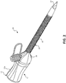
FIG. 2 is a side perspective view of the trocar assembly ofFIG. 1 in an assembled state; -
FIG. 3 is a top perspective view of the trocar assembly ofFIG. 2 in the assembled state; -
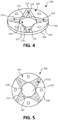
FIG. 4 is a top perspective view of an exemplary embodiment of a retention member for receipt in the obturator assembly ofFIG. 1 ; -
FIG. 5 is a top view of the retention member ofFIG. 4 ; -
FIG. 6 is a top view of another embodiment of a retention member for receipt in the obturator assembly ofFIG. 1 ; -
FIG. 7 is a top view of yet another embodiment of a retention member for receipt in the obturator assembly ofFIG. 1 ; -
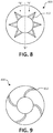
FIG. 8 is a top view of yet another embodiment of a retention member for receipt in the obturator assembly ofFIG. 1 ; and -
FIG. 9 is a top view of yet another embodiment of a retention member for receipt in the obturator assembly ofFIG. 1 . - The figures depict embodiments of the present disclosure for purposes of illustration only. One skilled in the art will readily recognize from the following discussion that alternative embodiments of the structures and methods illustrated herein may be employed without departing from the principles of the present disclosure described herein.
- Embodiments of the present disclosure are described hereinbelow with reference to the accompanying drawings. However, it is to be understood that the disclosed embodiments are merely exemplary of the disclosure and may be embodied in various forms. Well-known functions or constructions are not described in detail to avoid obscuring the present disclosure in unnecessary detail. Therefore, specific structural and functional details disclosed herein are not to be interpreted as limiting, but merely as a basis for the claims and as a representative basis for teaching one skilled in the art to variously employ the present disclosure in virtually any appropriately detailed structure.
- For the purposes of promoting an understanding of the principles of the present disclosure, reference will now be made to the exemplary embodiments illustrated in the drawings, and specific language will be used to describe the same. It will nevertheless be understood that no limitation of the scope of the present disclosure is thereby intended. Any alterations and further modifications of the inventive features illustrated herein, and any additional applications of the principles of the present disclosure as illustrated herein, which would occur to one skilled in the relevant art and having possession of this disclosure, are to be considered within the scope of the present disclosure.
- The present disclosure, in accordance with various example embodiments thereof, relates to an optical trocar system that provides access to a body cavity through an anatomical, e.g., abdominal, wall. It should be noted that, for the purposes of this description, the term optical trocar system may be used herein synonymously with the term visual obturator system. Advantageously, the optical trocar system of the present disclosure, in accordance with various embodiments thereof, includes a retention member designed to stabilize a surgical instrument
- (e.g., an endoscope or a laparoscope) relative to and within the optical trocar system. The retention member may be constructed from a unitary piece of elastomeric material and have a plurality of reduced-thickness sections disposed around a central opening thereof. The reduced-thickness sections allow for the retention member to flex upon receipt of a surgical instrument through the central opening. Disposed between the reduced-thickness sections are thicker sections that assist in stabilizing the surgical instrument within the central opening by inhibiting rotational movement and axial motion thereof during use.
- Referring now to
FIGS. 1-3 , there is illustrated an optical trocar, e.g., visual obturator, system orassembly 10 in accordance with an embodiment of the present disclosure. Thevisual obturator system 10 is intended for separating tissue planes in an endoscopic, e.g., laparoscopic, surgical procedure, and, is particularly suitable for the blunt dissection of the abdominal lining during a surgical procedure. Thevisual obturator system 10 is adapted to receive a surgical instrument, such as, for example, an endoscope, to permit viewing of tissue during the insertion and advancement of thevisual obturator system 10 toward the operative site. - In accordance with the embodiment shown, the
visual obturator system 10 generally includes anobturator assembly 11 and acannula assembly 30 which at least partially receives theobturator assembly 11. Thecannula assembly 30 of thevisual obturator system 10 includes a clear elongatedportion 32, defining a longitudinal axis "B-B," and ahead 34 monolithically formed with or connected to a proximal end portion of theelongated portion 32. - The
obturator assembly 11 of thevisual obturator system 10 includes anobturator housing assembly 12 disposed in mechanical cooperation with anelongated obturator shaft 14 of theobturator assembly 11. Theobturator housing assembly 12 includes anouter housing 12a, and aninner housing 12b supported on a proximal end portion of theelongated obturator shaft 14. Theouter housing 12a may be constructed from two half-sections joined to one another. Theouter housing 12a defines acavity 16 therein in which theinner housing 12b is situated. Theinner housing 12b defines acentral passageway 18 extending longitudinally therethrough that is coaxial with a longitudinal axis "A-A" defined by theelongated obturator shaft 14. Theelongated obturator shaft 14 extends distally from theobturator housing assembly 12 and may be rigid, e.g., metal. Theelongated obturator shaft 14 may be attached, e.g., by over molding thereto, at its proximal end portion to theobturator housing assembly 12 and at its distal end portion to anoptical member 20. - The
optical member 20 may be fabricated from a polymeric material, e.g., LEXAN, and is transparent, or at least semi-transparent, to permit passage of light rays. During assembly, theoptical member 20 may be over-molded onto the distal end portion of themetal obturator shaft 14 to connect the components. Theoptical member 20 defines an internal chamfered or sloped surface (not explicitly shown) which is obliquely arranged relative to the longitudinal axis A-A. During use, the chamfered surface of theoptical member 20 is directly engaged by the outermost periphery of a distal end of an endoscope (not shown), such that light transmitted from regions of the endoscope travel radially within the outer periphery across an air gap prior to being received by the chamfered or sloped surface of theoptical member 20. Theoptical member 20 permits the passage of light rays to enable viewing (by the endoscope) of tissue adjacent theoptical member 20 during the insertion and/or advancement of thevisual obturator system 10 through the tissue. - With specific reference to
FIGS. 3-5 , theobturator assembly 11 further includes aretention member 100 disposed between the outer andinner housings obturator housing assembly 12 and within the cavity 16 (FIG. 1 ) of theobturator housing assembly 12. Theretention member 100 includes amain body 101 that defines acentral opening 102 coaxially aligned with each of the passageway 18 (FIG. 1 ) of theinner housing 12b, the longitudinal axis A-A of theelongated obturator shaft 14, and the longitudinal axis B-B of theelongated portion 32 of thecannula assembly 30. Thecentral opening 102 is dimensioned to receive a surgical instrument therethrough. Theretention member 100 is constructed of a unitary piece of elastomeric material, such as an elastomer (e.g., rubber or silicone), and is adapted to engage an outer surface of a surgical instrument to assist in retaining the relative positioning of the surgical instrument within theoptical trocar system 10. - The
retention member 100 may have a generally planar, disc-shaped configuration. In some embodiments, theretention member 100 may assume any suitable configuration such as squared or triangular. Themain body 101 of theretention member 100 has anupper surface 104, alower surface 106, an outerperipheral surface 108, and an innerperipheral surface 110 that defines thecentral opening 102. Themain body 101 defines a first thickness between the upper andlower surfaces - The
retention member 100 further includes a plurality offirst sections 112 formed in themain body 101 of theretention member 100. The first sections are circumferentially disposed about theopening 102 in themain body 101 of theretention member 100. Thefirst sections 112 may be equally circumferentially spaced from one another about theopening 102 or unevenly circumferentially spaced about theopening 102. Thefirst sections 112 may be depressions formed in theupper surface 104 of themain body 101 of theretention member 100, such that thefirst sections 112 have a reduced thickness relative to themain body 101 of theretention member 100. - In embodiments, the
first sections 112 may have a reduced thickness relative to the entiremain body 101 of theretention member 100 or only portions thereof. In embodiments, the first sections ordepressions 112 may be formed in one or both of the upper andlower surfaces main body 101 of theretention member 100. In still other embodiments, rather than having a reduced thickness, thefirst sections 112 may have the same thickness as the remainder of themain body 101 of theretention member 100, but be fabricated from a relatively more flexible material than themain body 101. Thefirst sections 112 are configured to permit flexure of theretention member 100 and enlargement of thecentral opening 102 upon insertion of a surgical instrument. - In some embodiments, only the inner
peripheral surface 110 of theretention member 100 has a reduced thickness relative to the remainder of theretention member 100. It is contemplated that thefirst sections 112 may be disposed on only one side of theretention member 100. - The
first sections 112 extend radially outward from the innerperipheral surface 110 of themain body 101 of theretention member 100 toward the outerperipheral surface 108 of themain body 101 of theretention member 100. Thefirst sections 112 may each have anouter edge 116 coincident with the outerperipheral surface 108. In another embodiment of aretention member 200, shown inFIG. 6 , theouter edge 216 of thefirst sections 212 may be disposed radially inward of the outerperipheral surface 208 of theretention member 200. - With continued reference to
FIGS. 3-5 , each of thefirst sections 112 has a triangular configuration, wherein a base of each thefirst sections 112 is disposed adjacent the innerperipheral surface 110, and an apex of each of thefirst sections 112 is disposed adjacent the outerperipheral surface 108. In another embodiment of aretention member 300, shown inFIG. 7 , thefirst sections 312 of theretention member 300 may assume a rectangular shape. It is contemplated that thefirst sections 112 may assume other shapes not illustrated herein, such as, for example, circular, oblong, or any suitable shape. - With continued reference to
FIGS. 3-5 , each of thefirst sections 112 includes abottom surface 120 and atransition surface 122. Thebottom surface 120 of each of thefirst sections 112 is coplanar or substantially coplanar with the upper andlower surfaces retention member 100. Thetransition surface 122 may assume a curved or flat configuration and partially or completely surrounds thebottom surface 120. The transition surface extends transversely or obliquely between thebottom surface 120 of thefirst section 112 and theupper surface 104 of theretention member 100. In embodiments, thetransition surface 122 may extend perpendicularly relative to the upper andlower surfaces retention member 100. Thetransition surface 122 facilitates a smooth entry of an endoscope or other surgical instrument through theopening 102 of theretention member 100. - In yet another embodiment of a
retention member 400, shown inFIG. 8 , thefirst sections 412 may be isolated into first and second groups "X" and "Y" rather than be spaced equidistantly. In particular, the first group "X" is disposed on a first side of a plane "P" extending perpendicularly through a center of theretention member 400, and the second group "Y" is disposed on a second side of the plane "P." - The operation of the
optical trocar system 10 and, specifically theobturator assembly 11 will now be described. Theobturator assembly 11 of theoptical trocar system 10 is inserted through thecannula assembly 30 of theoptical trocar system 10. The assembledoptical trocar system 10 is positioned within an initial incision and against targeted tissue, e.g., an abdominal lining. A surgical instrument, such as an endoscope (not shown), is inserted through theobturator housing assembly 12 of theobturator assembly 11 and, in turn, theopening 102 of theretention member 100. - Due to the
first sections 112 of theretention member 100 having a reduced thickness relative to themain body 101 thereof, theopening 102 in theretention member 100 dilates to accommodate the endoscope, whereby the innerperipheral surface 110 of theretention member 100 forms a friction fit with an outer surface of the endoscope. Advancement of the endoscope through theretention member 100 is continued to position a distal viewing end of the endoscope against the chamfered surface of the transparentoptical member 20. Upon the endoscope being positioned at the desired location within theoptical trocar system 10, the thickermain body 101 of theretention member 100 resists a change in the angular orientation of the endoscope within theobturator assembly 11. - With reference to
FIG. 9 , another embodiment of aretention member 400 is illustrated, similar to the retention members described above. Theretention member 400 of the present embodiment differs from those above by having a plurality of reduced-thickness portions 412 that spiral from a center of theretention member 400. - While several embodiments of the disclosure have been shown in the drawings, it is not intended that the disclosure be limited thereto, as it is intended that the disclosure be as broad in scope as the art will allow and that the specification be read likewise. Therefore, the above description should not be construed as limiting, but merely as exemplifications of presently disclosed embodiments. Thus the scope of the embodiments should be determined by the appended claims and their legal equivalents, rather than by the examples given.
- Persons skilled in the art will understand that the devices and methods specifically described herein and illustrated in the accompanying drawings are non-limiting exemplary embodiments. The features illustrated or described in connection with one exemplary embodiment may be combined with the features of other embodiments. Such modifications and variations are intended to be included within the scope of the present disclosure. As well, one skilled in the art will appreciate further features and advantages of the present disclosure based on the above-described embodiments. Accordingly, the present disclosure is not to be limited by what has been particularly shown and described, except as indicated by the appended claims.
- The invention may be described by reference to the following numbered paragraphs:-
- 1. An obturator assembly including:
- an obturator housing defining a cavity therein;
- an obturator shaft extending distally from the housing; and
- a retention member disposed within the cavity of the obturator housing, the retention member including:
- a main body defining an opening dimensioned for receipt of a surgical instrument, the main body having a first thickness; and
- a plurality of first sections formed in the main body and circumferentially disposed about the opening, each section of the plurality of first sections having a second thickness that is less than the first thickness of the main body to facilitate flexing of the retention member during insertion of a surgical instrument into the opening.
- 2. The obturator assembly according to paragraph 1, wherein each section of the plurality of first sections extends radially outward from the opening.
- 3. The obturator assembly according to paragraph 1, wherein each section of the plurality of first sections extends from an inner peripheral surface of the main body of the retention member radially outward toward an outer peripheral surface of the main body of the retention member.
- 4. The obturator assembly according to paragraph 3, wherein each section of the plurality of first sections has an outer edge disposed inwardly of the outer peripheral surface.
- 5. The obturator assembly according to paragraph 3, wherein each section of the plurality of first sections has an outer edge coincident with the outer peripheral surface.
- 6. The obturator assembly according to paragraph 1, wherein each section of the plurality of first sections includes:
- a bottom surface; and
- a transition surface extending transversely between the bottom surface and one of an upper surface or a lower surface of the main body of the retention member.
- 7. The obturator assembly according to paragraph 1, wherein at least one first section of the plurality of first sections has a triangular configuration or a squared configuration.
- 8. The obturator assembly according to paragraph 1, wherein each section of the plurality of first sections is a depression formed in an upper surface or a lower surface of the main body of the retention member.
- 9. The obturator assembly according to paragraph 8, wherein the upper and lower surfaces of the main body of the retention member are planar.
- 10. The obturator assembly according to paragraph 1, wherein the retention member has a circular configuration.
- 11. The obturator assembly according to paragraph 1, wherein the opening is aligned with a central longitudinal axis defined by the obturator shaft.
- 12. The obturator assembly according to paragraph 1, wherein the retention member is fabricated from a unitary piece of elastic material.
- 13. The obturator assembly according to
paragraph 12, wherein the elastic material includes at least one of rubber or silicone. - 14. An optical trocar system, comprising:
- an obturator assembly including:
- an obturator housing defining a cavity therein;
- an obturator shaft extending distally from the housing; and
- a retention member disposed within the cavity of the obturator housing, the retention member including:
- a main body defining an opening dimensioned for receipt of a surgical instrument, the main body having a first thickness; and
- a plurality of first sections formed in the main body and circumferentially disposed about the opening, each section of the plurality of first sections having a second thickness that is less than the first thickness of the main body to facilitate flexing of the retention member during insertion of a surgical instrument into the opening; and
- a cannula assembly configured to receive the obturator shaft of the obturator assembly therein.
- an obturator assembly including:
- 15. The optical trocar assembly according to
paragraph 14, wherein each section of the plurality of first sections extends radially outward from the opening. - 16. The optical trocar assembly according to paragraph 15, wherein each section of the plurality of first sections is a depression formed in an upper surface or a lower surface of the main body of the retention member.
- 17. The optical trocar assembly according to
paragraph 14, wherein each section of the plurality of first sections extends from an inner peripheral surface of the main body of the retention member radially outward toward an outer peripheral surface of the main body of the retention member. - 18. The optical trocar assembly according to paragraph 17, wherein each section of the plurality of first sections has an outer edge disposed inwardly of the outer peripheral surface.
- 19. The optical trocar assembly according to
paragraph 14, wherein at least one first section of the plurality of first sections has a triangular configuration or a squared configuration. - 20. The optical trocar assembly according to
paragraph 14, wherein the retention member is fabricated from a unitary piece of elastic material.
Claims (15)
- An obturator assembly including:an obturator housing defining a cavity therein;an obturator shaft extending distally from the housing; anda retention member disposed within the cavity of the obturator housing, the retention member including:a main body defining an opening dimensioned for receipt of a surgical instrument, the main body having a first thickness; anda plurality of first sections formed in the main body and circumferentially disposed about the opening, each section of the plurality of first sections having a second thickness that is less than the first thickness of the main body to facilitate flexing of the retention member during insertion of a surgical instrument into the opening.
- The obturator assembly according to claim 1, wherein each section of the plurality of first sections extends radially outward from the opening.
- The obturator assembly according to claim 1, wherein each section of the plurality of first sections extends from an inner peripheral surface of the main body of the retention member radially outward toward an outer peripheral surface of the main body of the retention member.
- The obturator assembly according to claim 3, wherein each section of the plurality of first sections has an outer edge disposed inwardly of the outer peripheral surface.
- The obturator assembly according to claim 3, wherein each section of the plurality of first sections has an outer edge coincident with the outer peripheral surface.
- The obturator assembly according to any preceding claim, wherein each section of the plurality of first sections includes:a bottom surface; anda transition surface extending transversely between the bottom surface and one of an upper surface or a lower surface of the main body of the retention member.
- The obturator assembly according to claim 1, wherein at least one first section of the plurality of first sections has a triangular configuration or a squared configuration.
- The obturator assembly according to claim 1, wherein each section of the plurality of first sections is a depression formed in an upper surface or a lower surface of the main body of the retention member; preferably, wherein the upper and lower surfaces of the main body of the retention member are planar.
- The obturator assembly according to any preceding claim, wherein the retention member has a circular configuration; and/or wherein the opening is aligned with a central longitudinal axis defined by the obturator shaft.
- The obturator assembly according to any preceding claim, wherein the retention member is fabricated from a unitary piece of elastic material; preferably wherein the elastic material includes at least one of rubber or silicone.
- An optical trocar system, comprising:an obturator assembly including:an obturator housing defining a cavity therein;an obturator shaft extending distally from the housing; anda retention member disposed within the cavity of the obturator housing, the retention member including:a main body defining an opening dimensioned for receipt of a surgical instrument, the main body having a first thickness; anda plurality of first sections formed in the main body and circumferentially disposed about the opening, each section of the plurality of first sections having a second thickness that is less than the first thickness of the main body to facilitate flexing of the retention member during insertion of a surgical instrument into the opening; anda cannula assembly configured to receive the obturator shaft of the obturator assembly therein.
- The optical trocar assembly according to claim 11, wherein each section of the plurality of first sections extends radially outward from the opening; preferably wherein each section of the plurality of first sections is a depression formed in an upper surface or a lower surface of the main body of the retention member.
- The optical trocar assembly according to claim 11 or claim 12, wherein each section of the plurality of first sections extends from an inner peripheral surface of the main body of the retention member radially outward toward an outer peripheral surface of the main body of the retention member; preferably wherein each section of the plurality of first sections has an outer edge disposed inwardly of the outer peripheral surface.
- The optical trocar assembly according to any of claims 11 to 13, wherein at least one first section of the plurality of first sections has a triangular configuration or a squared configuration.
- The optical trocar assembly according to any of claims 11 to 14, wherein the retention member is fabricated from a unitary piece of elastic material.
Applications Claiming Priority (1)
| Application Number | Priority Date | Filing Date | Title |
|---|---|---|---|
| US15/919,854 US10722111B2 (en) | 2018-03-13 | 2018-03-13 | Optical trocar assembly |
Publications (2)
| Publication Number | Publication Date |
|---|---|
| EP3539490A1 true EP3539490A1 (en) | 2019-09-18 |
| EP3539490B1 EP3539490B1 (en) | 2020-12-23 |
Family
ID=65766882
Family Applications (1)
| Application Number | Title | Priority Date | Filing Date |
|---|---|---|---|
| EP19162107.7A Active EP3539490B1 (en) | 2018-03-13 | 2019-03-12 | Optical trocar assembly |
Country Status (5)
| Country | Link |
|---|---|
| US (1) | US10722111B2 (en) |
| EP (1) | EP3539490B1 (en) |
| JP (1) | JP7300848B2 (en) |
| AU (1) | AU2019201059A1 (en) |
| CA (1) | CA3034339A1 (en) |
Cited By (1)
| Publication number | Priority date | Publication date | Assignee | Title |
|---|---|---|---|---|
| KR20240165058A (en) * | 2023-05-15 | 2024-11-22 | 울산대학교 산학협력단 | Trocar assembly for laparoscopic surgery |
Families Citing this family (4)
| Publication number | Priority date | Publication date | Assignee | Title |
|---|---|---|---|---|
| US11406420B2 (en) * | 2019-10-11 | 2022-08-09 | Covidien Lp | Two point contact flange for instrument seals |
| USD951445S1 (en) * | 2020-01-10 | 2022-05-10 | Livsmed Inc. | Trocar for surgical instrument |
| KR102502906B1 (en) * | 2020-02-28 | 2023-02-23 | 박진서 | An Obturator with a Function of Regulating an Inflow of a Gas |
| CN111658150B (en) * | 2020-06-24 | 2025-04-22 | 哈尔滨思哲睿智能医疗设备股份有限公司 | Laparoscopic bacteria-isolating locking interface and laparoscopic surgical robot |
Citations (5)
| Publication number | Priority date | Publication date | Assignee | Title |
|---|---|---|---|---|
| WO1999052577A1 (en) * | 1998-04-13 | 1999-10-21 | Applied Medical Resources Corporation | Cone-shaped universal seal having nonuniform surface and seal assembly including same |
| CN101259030A (en) * | 2008-04-18 | 2008-09-10 | 周星 | Puncture device general purpose type radial direction seal ring and puncture device |
| WO2011044118A1 (en) * | 2009-10-08 | 2011-04-14 | Ethicon Endo-Surgery, Inc. | Trocar assembly |
| US20110288483A1 (en) * | 2009-01-23 | 2011-11-24 | Xing Zhou | Groove Universal Radial Seal Ring Used in a Trocar and Trocar |
| US20140249371A1 (en) * | 2011-10-18 | 2014-09-04 | Covidien Lp | Optical trocar system |
Family Cites Families (38)
| Publication number | Priority date | Publication date | Assignee | Title |
|---|---|---|---|---|
| US5685820A (en) | 1990-11-06 | 1997-11-11 | Partomed Medizintechnik Gmbh | Instrument for the penetration of body tissue |
| US5743884A (en) * | 1992-12-17 | 1998-04-28 | Hasson; Harrith M. | Sealing structure for medical instrument |
| US5342315A (en) * | 1993-04-12 | 1994-08-30 | Ethicon, Inc. | Trocar seal/protector assemblies |
| US5725477A (en) | 1993-11-18 | 1998-03-10 | Asahi Kogaku Kogyo Kabushiki Kaisha | Front end structure of endoscope |
| US5685823A (en) | 1994-03-30 | 1997-11-11 | Asahi Kogaku Kogyo Kabushiki Kaisha | End structure of endoscope |
| JPH08182648A (en) | 1994-12-27 | 1996-07-16 | Olympus Optical Co Ltd | Endoscope with detachable front end cover |
| US5569292A (en) | 1995-02-01 | 1996-10-29 | Ethicon Endo-Surgery, Inc. | Surgical penetration instrument with transparent blades and tip cover |
| US5817061A (en) | 1997-05-16 | 1998-10-06 | Ethicon Endo-Surgery, Inc. | Trocar assembly |
| EP0979635A2 (en) | 1998-08-12 | 2000-02-16 | Origin Medsystems, Inc. | Tissue dissector apparatus |
| US7485092B1 (en) | 1998-08-12 | 2009-02-03 | Maquet Cardiovascular Llc | Vessel harvesting apparatus and method |
| US6582357B2 (en) | 2000-05-24 | 2003-06-24 | Pentax Corporation | Treating instrument erecting device for use in endoscope |
| JP3533163B2 (en) | 2000-09-18 | 2004-05-31 | ペンタックス株式会社 | Endoscope tip |
| JP3845296B2 (en) | 2000-11-29 | 2006-11-15 | オリンパス株式会社 | Endoscope dirt remover |
| EP2428172B1 (en) | 2001-09-24 | 2013-07-24 | Applied Medical Resources Corporation | Bladeless obturator |
| US20050033237A1 (en) | 2003-08-08 | 2005-02-10 | James Fentress | Catheter assemblies and injection molding processes and equipment for making the same |
| EP2545865B1 (en) | 2003-10-03 | 2015-07-08 | Applied Medical Resources Corporation | Bladeless optical obturator |
| US20050149096A1 (en) | 2003-12-23 | 2005-07-07 | Hilal Said S. | Catheter with conduit traversing tip |
| AU2005228956B2 (en) | 2004-03-23 | 2011-08-18 | Boston Scientific Limited | In-vivo visualization system |
| EP3175804B1 (en) | 2004-06-29 | 2018-09-26 | Applied Medical Resources Corporation | Insufflating optical surgical instrument |
| US8241251B2 (en) | 2004-08-25 | 2012-08-14 | Tyco Healthcare Group Lp | Gel seal for a surgical trocar apparatus |
| US7470230B2 (en) | 2005-03-31 | 2008-12-30 | Tyco Healthcare Group Lp | Optical obturator |
| US7824327B2 (en) | 2005-04-12 | 2010-11-02 | Tyco Healthcare Group Llp | Optical trocar with scope holding assembly |
| US8932208B2 (en) | 2005-05-26 | 2015-01-13 | Maquet Cardiovascular Llc | Apparatus and methods for performing minimally-invasive surgical procedures |
| US8430851B2 (en) | 2005-10-14 | 2013-04-30 | Applied Medical Resources Corporation | Surgical access port |
| US8926506B2 (en) * | 2009-03-06 | 2015-01-06 | Ethicon Endo-Surgery, Inc. | Methods and devices for providing access into a body cavity |
| US20070260121A1 (en) | 2006-05-08 | 2007-11-08 | Ethicon Endo-Surgery, Inc. | Endoscopic Translumenal Surgical Systems |
| WO2008045316A2 (en) | 2006-10-06 | 2008-04-17 | Surgiquest, Incorporated | Visualization trocar |
| CA2669983A1 (en) | 2006-12-20 | 2008-07-03 | Tyco Healthcare Group Lp | Surgical visual obturator |
| WO2008103400A2 (en) | 2007-02-21 | 2008-08-28 | Tyco Healthcare Group Lp | Obturator tips |
| EP2142115B1 (en) | 2007-04-18 | 2016-08-24 | Covidien LP | Trocar assembly with obturator dissector |
| EP1994894A1 (en) | 2007-05-22 | 2008-11-26 | Tyco Healthcare Group LP | Access assembly with ribbed seal |
| AU2008202266B2 (en) | 2007-06-01 | 2013-09-12 | Covidien Lp | Obturator tips |
| US9226774B2 (en) | 2009-12-17 | 2016-01-05 | Covidien Lp | Visual obturator with tip openings |
| WO2011075512A2 (en) | 2009-12-18 | 2011-06-23 | Wilson-Cook Medical Inc. | Endoscope sheath |
| EP2900153B1 (en) * | 2012-09-28 | 2018-05-30 | Covidien LP | Optical trocar visualization system and apparatus |
| US9955998B2 (en) * | 2013-02-21 | 2018-05-01 | Covidien Lp | Surgical access device including lateral moving seal cooperating with bellows attached to proximal wall of cannula housing |
| US20140235946A1 (en) * | 2013-02-21 | 2014-08-21 | Covidien Lp | Optical obturator visualization system |
| US20150031958A1 (en) * | 2013-07-25 | 2015-01-29 | Covidien Lp | Surgical seal assembly with upper lip seal |
-
2018
- 2018-03-13 US US15/919,854 patent/US10722111B2/en active Active
-
2019
- 2019-02-15 AU AU2019201059A patent/AU2019201059A1/en not_active Abandoned
- 2019-02-20 CA CA3034339A patent/CA3034339A1/en not_active Abandoned
- 2019-03-01 JP JP2019037597A patent/JP7300848B2/en active Active
- 2019-03-12 EP EP19162107.7A patent/EP3539490B1/en active Active
Patent Citations (5)
| Publication number | Priority date | Publication date | Assignee | Title |
|---|---|---|---|---|
| WO1999052577A1 (en) * | 1998-04-13 | 1999-10-21 | Applied Medical Resources Corporation | Cone-shaped universal seal having nonuniform surface and seal assembly including same |
| CN101259030A (en) * | 2008-04-18 | 2008-09-10 | 周星 | Puncture device general purpose type radial direction seal ring and puncture device |
| US20110288483A1 (en) * | 2009-01-23 | 2011-11-24 | Xing Zhou | Groove Universal Radial Seal Ring Used in a Trocar and Trocar |
| WO2011044118A1 (en) * | 2009-10-08 | 2011-04-14 | Ethicon Endo-Surgery, Inc. | Trocar assembly |
| US20140249371A1 (en) * | 2011-10-18 | 2014-09-04 | Covidien Lp | Optical trocar system |
Cited By (1)
| Publication number | Priority date | Publication date | Assignee | Title |
|---|---|---|---|---|
| KR20240165058A (en) * | 2023-05-15 | 2024-11-22 | 울산대학교 산학협력단 | Trocar assembly for laparoscopic surgery |
Also Published As
| Publication number | Publication date |
|---|---|
| JP2019155090A (en) | 2019-09-19 |
| US20190282081A1 (en) | 2019-09-19 |
| AU2019201059A1 (en) | 2019-10-03 |
| CA3034339A1 (en) | 2019-09-13 |
| US10722111B2 (en) | 2020-07-28 |
| EP3539490B1 (en) | 2020-12-23 |
| JP7300848B2 (en) | 2023-06-30 |
Similar Documents
| Publication | Publication Date | Title |
|---|---|---|
| US11832849B2 (en) | Surgical access device | |
| US11529169B2 (en) | Optical trocar visualization system and apparatus | |
| EP3539490B1 (en) | Optical trocar assembly | |
| US10828065B2 (en) | Surgical access system | |
| US10813536B2 (en) | Optical trocar system | |
| US10092321B2 (en) | Bladeless obturators and bladeless obturator members | |
| EP2687169B1 (en) | Structure for selectively locking portions of a seal assembly | |
| EP2684532A2 (en) | Surgical seal assembly including a guard member | |
| EP2335623A1 (en) | Surgical access apparatus with constraining mechanism |
Legal Events
| Date | Code | Title | Description |
|---|---|---|---|
| PUAI | Public reference made under article 153(3) epc to a published international application that has entered the european phase |
Free format text: ORIGINAL CODE: 0009012 |
|
| STAA | Information on the status of an ep patent application or granted ep patent |
Free format text: STATUS: THE APPLICATION HAS BEEN PUBLISHED |
|
| AK | Designated contracting states |
Kind code of ref document: A1 Designated state(s): AL AT BE BG CH CY CZ DE DK EE ES FI FR GB GR HR HU IE IS IT LI LT LU LV MC MK MT NL NO PL PT RO RS SE SI SK SM TR |
|
| AX | Request for extension of the european patent |
Extension state: BA ME |
|
| STAA | Information on the status of an ep patent application or granted ep patent |
Free format text: STATUS: REQUEST FOR EXAMINATION WAS MADE |
|
| 17P | Request for examination filed |
Effective date: 20200313 |
|
| RBV | Designated contracting states (corrected) |
Designated state(s): AL AT BE BG CH CY CZ DE DK EE ES FI FR GB GR HR HU IE IS IT LI LT LU LV MC MK MT NL NO PL PT RO RS SE SI SK SM TR |
|
| STAA | Information on the status of an ep patent application or granted ep patent |
Free format text: STATUS: EXAMINATION IS IN PROGRESS |
|
| 17Q | First examination report despatched |
Effective date: 20200610 |
|
| GRAP | Despatch of communication of intention to grant a patent |
Free format text: ORIGINAL CODE: EPIDOSNIGR1 |
|
| STAA | Information on the status of an ep patent application or granted ep patent |
Free format text: STATUS: GRANT OF PATENT IS INTENDED |
|
| INTG | Intention to grant announced |
Effective date: 20200730 |
|
| GRAS | Grant fee paid |
Free format text: ORIGINAL CODE: EPIDOSNIGR3 |
|
| GRAA | (expected) grant |
Free format text: ORIGINAL CODE: 0009210 |
|
| STAA | Information on the status of an ep patent application or granted ep patent |
Free format text: STATUS: THE PATENT HAS BEEN GRANTED |
|
| AK | Designated contracting states |
Kind code of ref document: B1 Designated state(s): AL AT BE BG CH CY CZ DE DK EE ES FI FR GB GR HR HU IE IS IT LI LT LU LV MC MK MT NL NO PL PT RO RS SE SI SK SM TR |
|
| REG | Reference to a national code |
Ref country code: GB Ref legal event code: FG4D |
|
| REG | Reference to a national code |
Ref country code: DE Ref legal event code: R096 Ref document number: 602019001818 Country of ref document: DE |
|
| REG | Reference to a national code |
Ref country code: AT Ref legal event code: REF Ref document number: 1346946 Country of ref document: AT Kind code of ref document: T Effective date: 20210115 |
|
| REG | Reference to a national code |
Ref country code: IE Ref legal event code: FG4D |
|
| REG | Reference to a national code |
Ref country code: DE Ref legal event code: R082 Ref document number: 602019001818 Country of ref document: DE Representative=s name: WR SERVICES GMBH, DE |
|
| PG25 | Lapsed in a contracting state [announced via postgrant information from national office to epo] |
Ref country code: GR Free format text: LAPSE BECAUSE OF FAILURE TO SUBMIT A TRANSLATION OF THE DESCRIPTION OR TO PAY THE FEE WITHIN THE PRESCRIBED TIME-LIMIT Effective date: 20210324 Ref country code: NO Free format text: LAPSE BECAUSE OF FAILURE TO SUBMIT A TRANSLATION OF THE DESCRIPTION OR TO PAY THE FEE WITHIN THE PRESCRIBED TIME-LIMIT Effective date: 20210323 Ref country code: FI Free format text: LAPSE BECAUSE OF FAILURE TO SUBMIT A TRANSLATION OF THE DESCRIPTION OR TO PAY THE FEE WITHIN THE PRESCRIBED TIME-LIMIT Effective date: 20201223 Ref country code: RS Free format text: LAPSE BECAUSE OF FAILURE TO SUBMIT A TRANSLATION OF THE DESCRIPTION OR TO PAY THE FEE WITHIN THE PRESCRIBED TIME-LIMIT Effective date: 20201223 |
|
| REG | Reference to a national code |
Ref country code: AT Ref legal event code: MK05 Ref document number: 1346946 Country of ref document: AT Kind code of ref document: T Effective date: 20201223 |
|
| REG | Reference to a national code |
Ref country code: NL Ref legal event code: MP Effective date: 20201223 |
|
| PG25 | Lapsed in a contracting state [announced via postgrant information from national office to epo] |
Ref country code: SE Free format text: LAPSE BECAUSE OF FAILURE TO SUBMIT A TRANSLATION OF THE DESCRIPTION OR TO PAY THE FEE WITHIN THE PRESCRIBED TIME-LIMIT Effective date: 20201223 Ref country code: LV Free format text: LAPSE BECAUSE OF FAILURE TO SUBMIT A TRANSLATION OF THE DESCRIPTION OR TO PAY THE FEE WITHIN THE PRESCRIBED TIME-LIMIT Effective date: 20201223 Ref country code: BG Free format text: LAPSE BECAUSE OF FAILURE TO SUBMIT A TRANSLATION OF THE DESCRIPTION OR TO PAY THE FEE WITHIN THE PRESCRIBED TIME-LIMIT Effective date: 20210323 |
|
| PG25 | Lapsed in a contracting state [announced via postgrant information from national office to epo] |
Ref country code: NL Free format text: LAPSE BECAUSE OF FAILURE TO SUBMIT A TRANSLATION OF THE DESCRIPTION OR TO PAY THE FEE WITHIN THE PRESCRIBED TIME-LIMIT Effective date: 20201223 Ref country code: HR Free format text: LAPSE BECAUSE OF FAILURE TO SUBMIT A TRANSLATION OF THE DESCRIPTION OR TO PAY THE FEE WITHIN THE PRESCRIBED TIME-LIMIT Effective date: 20201223 |
|
| REG | Reference to a national code |
Ref country code: LT Ref legal event code: MG9D |
|
| PG25 | Lapsed in a contracting state [announced via postgrant information from national office to epo] |
Ref country code: CZ Free format text: LAPSE BECAUSE OF FAILURE TO SUBMIT A TRANSLATION OF THE DESCRIPTION OR TO PAY THE FEE WITHIN THE PRESCRIBED TIME-LIMIT Effective date: 20201223 Ref country code: EE Free format text: LAPSE BECAUSE OF FAILURE TO SUBMIT A TRANSLATION OF THE DESCRIPTION OR TO PAY THE FEE WITHIN THE PRESCRIBED TIME-LIMIT Effective date: 20201223 Ref country code: SM Free format text: LAPSE BECAUSE OF FAILURE TO SUBMIT A TRANSLATION OF THE DESCRIPTION OR TO PAY THE FEE WITHIN THE PRESCRIBED TIME-LIMIT Effective date: 20201223 Ref country code: SK Free format text: LAPSE BECAUSE OF FAILURE TO SUBMIT A TRANSLATION OF THE DESCRIPTION OR TO PAY THE FEE WITHIN THE PRESCRIBED TIME-LIMIT Effective date: 20201223 Ref country code: LT Free format text: LAPSE BECAUSE OF FAILURE TO SUBMIT A TRANSLATION OF THE DESCRIPTION OR TO PAY THE FEE WITHIN THE PRESCRIBED TIME-LIMIT Effective date: 20201223 Ref country code: RO Free format text: LAPSE BECAUSE OF FAILURE TO SUBMIT A TRANSLATION OF THE DESCRIPTION OR TO PAY THE FEE WITHIN THE PRESCRIBED TIME-LIMIT Effective date: 20201223 Ref country code: PT Free format text: LAPSE BECAUSE OF FAILURE TO SUBMIT A TRANSLATION OF THE DESCRIPTION OR TO PAY THE FEE WITHIN THE PRESCRIBED TIME-LIMIT Effective date: 20210423 |
|
| PG25 | Lapsed in a contracting state [announced via postgrant information from national office to epo] |
Ref country code: PL Free format text: LAPSE BECAUSE OF FAILURE TO SUBMIT A TRANSLATION OF THE DESCRIPTION OR TO PAY THE FEE WITHIN THE PRESCRIBED TIME-LIMIT Effective date: 20201223 Ref country code: AT Free format text: LAPSE BECAUSE OF FAILURE TO SUBMIT A TRANSLATION OF THE DESCRIPTION OR TO PAY THE FEE WITHIN THE PRESCRIBED TIME-LIMIT Effective date: 20201223 |
|
| REG | Reference to a national code |
Ref country code: DE Ref legal event code: R097 Ref document number: 602019001818 Country of ref document: DE |
|
| PG25 | Lapsed in a contracting state [announced via postgrant information from national office to epo] |
Ref country code: IS Free format text: LAPSE BECAUSE OF FAILURE TO SUBMIT A TRANSLATION OF THE DESCRIPTION OR TO PAY THE FEE WITHIN THE PRESCRIBED TIME-LIMIT Effective date: 20210423 |
|
| PG25 | Lapsed in a contracting state [announced via postgrant information from national office to epo] |
Ref country code: IT Free format text: LAPSE BECAUSE OF FAILURE TO SUBMIT A TRANSLATION OF THE DESCRIPTION OR TO PAY THE FEE WITHIN THE PRESCRIBED TIME-LIMIT Effective date: 20201223 Ref country code: MC Free format text: LAPSE BECAUSE OF FAILURE TO SUBMIT A TRANSLATION OF THE DESCRIPTION OR TO PAY THE FEE WITHIN THE PRESCRIBED TIME-LIMIT Effective date: 20201223 Ref country code: AL Free format text: LAPSE BECAUSE OF FAILURE TO SUBMIT A TRANSLATION OF THE DESCRIPTION OR TO PAY THE FEE WITHIN THE PRESCRIBED TIME-LIMIT Effective date: 20201223 |
|
| PLBE | No opposition filed within time limit |
Free format text: ORIGINAL CODE: 0009261 |
|
| STAA | Information on the status of an ep patent application or granted ep patent |
Free format text: STATUS: NO OPPOSITION FILED WITHIN TIME LIMIT |
|
| PG25 | Lapsed in a contracting state [announced via postgrant information from national office to epo] |
Ref country code: DK Free format text: LAPSE BECAUSE OF FAILURE TO SUBMIT A TRANSLATION OF THE DESCRIPTION OR TO PAY THE FEE WITHIN THE PRESCRIBED TIME-LIMIT Effective date: 20201223 |
|
| 26N | No opposition filed |
Effective date: 20210924 |
|
| REG | Reference to a national code |
Ref country code: BE Ref legal event code: MM Effective date: 20210331 |
|
| PG25 | Lapsed in a contracting state [announced via postgrant information from national office to epo] |
Ref country code: ES Free format text: LAPSE BECAUSE OF FAILURE TO SUBMIT A TRANSLATION OF THE DESCRIPTION OR TO PAY THE FEE WITHIN THE PRESCRIBED TIME-LIMIT Effective date: 20201223 Ref country code: IE Free format text: LAPSE BECAUSE OF NON-PAYMENT OF DUE FEES Effective date: 20210312 Ref country code: LU Free format text: LAPSE BECAUSE OF NON-PAYMENT OF DUE FEES Effective date: 20210312 |
|
| PG25 | Lapsed in a contracting state [announced via postgrant information from national office to epo] |
Ref country code: SI Free format text: LAPSE BECAUSE OF FAILURE TO SUBMIT A TRANSLATION OF THE DESCRIPTION OR TO PAY THE FEE WITHIN THE PRESCRIBED TIME-LIMIT Effective date: 20201223 |
|
| PG25 | Lapsed in a contracting state [announced via postgrant information from national office to epo] |
Ref country code: IS Free format text: LAPSE BECAUSE OF FAILURE TO SUBMIT A TRANSLATION OF THE DESCRIPTION OR TO PAY THE FEE WITHIN THE PRESCRIBED TIME-LIMIT Effective date: 20210423 |
|
| PG25 | Lapsed in a contracting state [announced via postgrant information from national office to epo] |
Ref country code: BE Free format text: LAPSE BECAUSE OF NON-PAYMENT OF DUE FEES Effective date: 20210331 |
|
| REG | Reference to a national code |
Ref country code: CH Ref legal event code: PL |
|
| PG25 | Lapsed in a contracting state [announced via postgrant information from national office to epo] |
Ref country code: LI Free format text: LAPSE BECAUSE OF NON-PAYMENT OF DUE FEES Effective date: 20220331 Ref country code: CH Free format text: LAPSE BECAUSE OF NON-PAYMENT OF DUE FEES Effective date: 20220331 |
|
| PG25 | Lapsed in a contracting state [announced via postgrant information from national office to epo] |
Ref country code: CY Free format text: LAPSE BECAUSE OF FAILURE TO SUBMIT A TRANSLATION OF THE DESCRIPTION OR TO PAY THE FEE WITHIN THE PRESCRIBED TIME-LIMIT Effective date: 20201223 |
|
| PG25 | Lapsed in a contracting state [announced via postgrant information from national office to epo] |
Ref country code: HU Free format text: LAPSE BECAUSE OF FAILURE TO SUBMIT A TRANSLATION OF THE DESCRIPTION OR TO PAY THE FEE WITHIN THE PRESCRIBED TIME-LIMIT; INVALID AB INITIO Effective date: 20190312 |
|
| PG25 | Lapsed in a contracting state [announced via postgrant information from national office to epo] |
Ref country code: MK Free format text: LAPSE BECAUSE OF FAILURE TO SUBMIT A TRANSLATION OF THE DESCRIPTION OR TO PAY THE FEE WITHIN THE PRESCRIBED TIME-LIMIT Effective date: 20201223 |
|
| PGFP | Annual fee paid to national office [announced via postgrant information from national office to epo] |
Ref country code: GB Payment date: 20240220 Year of fee payment: 6 |
|
| PGFP | Annual fee paid to national office [announced via postgrant information from national office to epo] |
Ref country code: FR Payment date: 20240220 Year of fee payment: 6 |
|
| PG25 | Lapsed in a contracting state [announced via postgrant information from national office to epo] |
Ref country code: TR Free format text: LAPSE BECAUSE OF FAILURE TO SUBMIT A TRANSLATION OF THE DESCRIPTION OR TO PAY THE FEE WITHIN THE PRESCRIBED TIME-LIMIT Effective date: 20201223 |
|
| PG25 | Lapsed in a contracting state [announced via postgrant information from national office to epo] |
Ref country code: MT Free format text: LAPSE BECAUSE OF FAILURE TO SUBMIT A TRANSLATION OF THE DESCRIPTION OR TO PAY THE FEE WITHIN THE PRESCRIBED TIME-LIMIT Effective date: 20201223 |
|
| GBPC | Gb: european patent ceased through non-payment of renewal fee |
Effective date: 20250312 |
|
| PG25 | Lapsed in a contracting state [announced via postgrant information from national office to epo] |
Ref country code: GB Free format text: LAPSE BECAUSE OF NON-PAYMENT OF DUE FEES Effective date: 20250312 |
|
| PG25 | Lapsed in a contracting state [announced via postgrant information from national office to epo] |
Ref country code: FR Free format text: LAPSE BECAUSE OF NON-PAYMENT OF DUE FEES Effective date: 20250331 |
|
| PGFP | Annual fee paid to national office [announced via postgrant information from national office to epo] |
Ref country code: DE Payment date: 20260219 Year of fee payment: 8 |