EP2900153B1 - Optical trocar visualization system and apparatus - Google Patents
Optical trocar visualization system and apparatus Download PDFInfo
- Publication number
- EP2900153B1 EP2900153B1 EP13841230.9A EP13841230A EP2900153B1 EP 2900153 B1 EP2900153 B1 EP 2900153B1 EP 13841230 A EP13841230 A EP 13841230A EP 2900153 B1 EP2900153 B1 EP 2900153B1
- Authority
- EP
- European Patent Office
- Prior art keywords
- seal
- assembly
- housing component
- septum
- obturator
- Prior art date
- Legal status (The legal status is an assumption and is not a legal conclusion. Google has not performed a legal analysis and makes no representation as to the accuracy of the status listed.)
- Active
Links
- 230000003287 optical effect Effects 0.000 title description 82
- 238000012800 visualization Methods 0.000 title description 23
- 239000000463 material Substances 0.000 claims description 20
- 230000002093 peripheral effect Effects 0.000 claims description 11
- 239000013536 elastomeric material Substances 0.000 claims description 5
- 230000000063 preceeding effect Effects 0.000 claims 1
- 210000001519 tissue Anatomy 0.000 description 46
- 230000007246 mechanism Effects 0.000 description 23
- 230000002265 prevention Effects 0.000 description 19
- 230000005641 tunneling Effects 0.000 description 18
- 238000000034 method Methods 0.000 description 11
- 238000001356 surgical procedure Methods 0.000 description 11
- 238000003780 insertion Methods 0.000 description 7
- 230000037431 insertion Effects 0.000 description 7
- 230000000712 assembly Effects 0.000 description 6
- 238000000429 assembly Methods 0.000 description 6
- 230000014759 maintenance of location Effects 0.000 description 6
- 210000000056 organ Anatomy 0.000 description 6
- 238000004519 manufacturing process Methods 0.000 description 4
- CURLTUGMZLYLDI-UHFFFAOYSA-N Carbon dioxide Chemical compound O=C=O CURLTUGMZLYLDI-UHFFFAOYSA-N 0.000 description 3
- 238000002224 dissection Methods 0.000 description 3
- 239000000835 fiber Substances 0.000 description 3
- 239000002184 metal Substances 0.000 description 3
- 229910052751 metal Inorganic materials 0.000 description 3
- 238000002324 minimally invasive surgery Methods 0.000 description 3
- 206010028980 Neoplasm Diseases 0.000 description 2
- 229910000831 Steel Inorganic materials 0.000 description 2
- 230000003187 abdominal effect Effects 0.000 description 2
- 229910002092 carbon dioxide Inorganic materials 0.000 description 2
- 239000002131 composite material Substances 0.000 description 2
- 210000004072 lung Anatomy 0.000 description 2
- 230000000149 penetrating effect Effects 0.000 description 2
- 229910001220 stainless steel Inorganic materials 0.000 description 2
- 239000010935 stainless steel Substances 0.000 description 2
- 239000010959 steel Substances 0.000 description 2
- 241001631457 Cannula Species 0.000 description 1
- 229920002430 Fibre-reinforced plastic Polymers 0.000 description 1
- 229920004142 LEXAN™ Polymers 0.000 description 1
- RTAQQCXQSZGOHL-UHFFFAOYSA-N Titanium Chemical compound [Ti] RTAQQCXQSZGOHL-UHFFFAOYSA-N 0.000 description 1
- 210000001015 abdomen Anatomy 0.000 description 1
- 210000000683 abdominal cavity Anatomy 0.000 description 1
- 230000002159 abnormal effect Effects 0.000 description 1
- 238000010521 absorption reaction Methods 0.000 description 1
- 210000000577 adipose tissue Anatomy 0.000 description 1
- 210000003484 anatomy Anatomy 0.000 description 1
- 210000000436 anus Anatomy 0.000 description 1
- 239000001569 carbon dioxide Substances 0.000 description 1
- 239000000919 ceramic Substances 0.000 description 1
- 230000008859 change Effects 0.000 description 1
- 238000012790 confirmation Methods 0.000 description 1
- 238000010276 construction Methods 0.000 description 1
- 230000008878 coupling Effects 0.000 description 1
- 238000010168 coupling process Methods 0.000 description 1
- 238000005859 coupling reaction Methods 0.000 description 1
- 230000007423 decrease Effects 0.000 description 1
- 201000010099 disease Diseases 0.000 description 1
- 208000037265 diseases, disorders, signs and symptoms Diseases 0.000 description 1
- 238000012976 endoscopic surgical procedure Methods 0.000 description 1
- 230000002708 enhancing effect Effects 0.000 description 1
- 239000011151 fibre-reinforced plastic Substances 0.000 description 1
- 210000000232 gallbladder Anatomy 0.000 description 1
- 238000003384 imaging method Methods 0.000 description 1
- 238000001727 in vivo Methods 0.000 description 1
- 230000000968 intestinal effect Effects 0.000 description 1
- 238000002357 laparoscopic surgery Methods 0.000 description 1
- 230000003902 lesion Effects 0.000 description 1
- 210000004185 liver Anatomy 0.000 description 1
- 230000002503 metabolic effect Effects 0.000 description 1
- 239000007769 metal material Substances 0.000 description 1
- 150000002739 metals Chemical class 0.000 description 1
- 238000012544 monitoring process Methods 0.000 description 1
- 238000000465 moulding Methods 0.000 description 1
- 210000002445 nipple Anatomy 0.000 description 1
- 238000002355 open surgical procedure Methods 0.000 description 1
- 230000035515 penetration Effects 0.000 description 1
- 239000004033 plastic Substances 0.000 description 1
- 229920003023 plastic Polymers 0.000 description 1
- 229920000642 polymer Polymers 0.000 description 1
- 229920001296 polysiloxane Polymers 0.000 description 1
- 230000002980 postoperative effect Effects 0.000 description 1
- 230000001681 protective effect Effects 0.000 description 1
- 230000002685 pulmonary effect Effects 0.000 description 1
- 210000005000 reproductive tract Anatomy 0.000 description 1
- 230000000717 retained effect Effects 0.000 description 1
- 238000000926 separation method Methods 0.000 description 1
- 210000004872 soft tissue Anatomy 0.000 description 1
- 210000002784 stomach Anatomy 0.000 description 1
- 238000006467 substitution reaction Methods 0.000 description 1
- 229920001169 thermoplastic Polymers 0.000 description 1
- 239000004416 thermosoftening plastic Substances 0.000 description 1
- 210000000115 thoracic cavity Anatomy 0.000 description 1
- 210000000779 thoracic wall Anatomy 0.000 description 1
- 230000008467 tissue growth Effects 0.000 description 1
- 239000010936 titanium Substances 0.000 description 1
- 229910052719 titanium Inorganic materials 0.000 description 1
- 238000002834 transmittance Methods 0.000 description 1
- 230000000472 traumatic effect Effects 0.000 description 1
- 210000001635 urinary tract Anatomy 0.000 description 1
- 210000001215 vagina Anatomy 0.000 description 1
- 210000001835 viscera Anatomy 0.000 description 1
- 230000000007 visual effect Effects 0.000 description 1
Images


Classifications
-
- A—HUMAN NECESSITIES
- A61—MEDICAL OR VETERINARY SCIENCE; HYGIENE
- A61B—DIAGNOSIS; SURGERY; IDENTIFICATION
- A61B17/00—Surgical instruments, devices or methods, e.g. tourniquets
- A61B17/34—Trocars; Puncturing needles
- A61B17/3462—Trocars; Puncturing needles with means for changing the diameter or the orientation of the entrance port of the cannula, e.g. for use with different-sized instruments, reduction ports, adapter seals
-
- A—HUMAN NECESSITIES
- A61—MEDICAL OR VETERINARY SCIENCE; HYGIENE
- A61B—DIAGNOSIS; SURGERY; IDENTIFICATION
- A61B17/00—Surgical instruments, devices or methods, e.g. tourniquets
- A61B17/02—Surgical instruments, devices or methods, e.g. tourniquets for holding wounds open; Tractors
- A61B17/0218—Surgical instruments, devices or methods, e.g. tourniquets for holding wounds open; Tractors for minimally invasive surgery
-
- A—HUMAN NECESSITIES
- A61—MEDICAL OR VETERINARY SCIENCE; HYGIENE
- A61B—DIAGNOSIS; SURGERY; IDENTIFICATION
- A61B17/00—Surgical instruments, devices or methods, e.g. tourniquets
- A61B17/34—Trocars; Puncturing needles
- A61B17/3417—Details of tips or shafts, e.g. grooves, expandable, bendable; Multiple coaxial sliding cannulas, e.g. for dilating
- A61B17/3421—Cannulas
- A61B17/3423—Access ports, e.g. toroid shape introducers for instruments or hands
-
- A—HUMAN NECESSITIES
- A61—MEDICAL OR VETERINARY SCIENCE; HYGIENE
- A61M—DEVICES FOR INTRODUCING MEDIA INTO, OR ONTO, THE BODY; DEVICES FOR TRANSDUCING BODY MEDIA OR FOR TAKING MEDIA FROM THE BODY; DEVICES FOR PRODUCING OR ENDING SLEEP OR STUPOR
- A61M39/00—Tubes, tube connectors, tube couplings, valves, access sites or the like, specially adapted for medical use
- A61M39/02—Access sites
- A61M39/06—Haemostasis valves, i.e. gaskets sealing around a needle, catheter or the like, closing on removal thereof
-
- A—HUMAN NECESSITIES
- A61—MEDICAL OR VETERINARY SCIENCE; HYGIENE
- A61B—DIAGNOSIS; SURGERY; IDENTIFICATION
- A61B17/00—Surgical instruments, devices or methods, e.g. tourniquets
- A61B2017/00831—Material properties
- A61B2017/00862—Material properties elastic or resilient
-
- A—HUMAN NECESSITIES
- A61—MEDICAL OR VETERINARY SCIENCE; HYGIENE
- A61B—DIAGNOSIS; SURGERY; IDENTIFICATION
- A61B17/00—Surgical instruments, devices or methods, e.g. tourniquets
- A61B17/34—Trocars; Puncturing needles
- A61B17/3417—Details of tips or shafts, e.g. grooves, expandable, bendable; Multiple coaxial sliding cannulas, e.g. for dilating
- A61B2017/3419—Sealing means between cannula and body
-
- A—HUMAN NECESSITIES
- A61—MEDICAL OR VETERINARY SCIENCE; HYGIENE
- A61B—DIAGNOSIS; SURGERY; IDENTIFICATION
- A61B17/00—Surgical instruments, devices or methods, e.g. tourniquets
- A61B17/34—Trocars; Puncturing needles
- A61B17/3417—Details of tips or shafts, e.g. grooves, expandable, bendable; Multiple coaxial sliding cannulas, e.g. for dilating
- A61B17/3421—Cannulas
- A61B2017/345—Cannulas for introduction into a natural body opening
- A61B2017/3452—Cannulas for introduction into a natural body opening for the rectum, e.g. for hemorrhoid surgery
-
- A—HUMAN NECESSITIES
- A61—MEDICAL OR VETERINARY SCIENCE; HYGIENE
- A61B—DIAGNOSIS; SURGERY; IDENTIFICATION
- A61B17/00—Surgical instruments, devices or methods, e.g. tourniquets
- A61B17/34—Trocars; Puncturing needles
- A61B17/3417—Details of tips or shafts, e.g. grooves, expandable, bendable; Multiple coaxial sliding cannulas, e.g. for dilating
- A61B2017/3454—Details of tips
- A61B2017/3456—Details of tips blunt
-
- A—HUMAN NECESSITIES
- A61—MEDICAL OR VETERINARY SCIENCE; HYGIENE
- A61B—DIAGNOSIS; SURGERY; IDENTIFICATION
- A61B17/00—Surgical instruments, devices or methods, e.g. tourniquets
- A61B17/34—Trocars; Puncturing needles
- A61B17/3417—Details of tips or shafts, e.g. grooves, expandable, bendable; Multiple coaxial sliding cannulas, e.g. for dilating
- A61B2017/3454—Details of tips
- A61B2017/346—Details of tips with wings
-
- A—HUMAN NECESSITIES
- A61—MEDICAL OR VETERINARY SCIENCE; HYGIENE
- A61M—DEVICES FOR INTRODUCING MEDIA INTO, OR ONTO, THE BODY; DEVICES FOR TRANSDUCING BODY MEDIA OR FOR TAKING MEDIA FROM THE BODY; DEVICES FOR PRODUCING OR ENDING SLEEP OR STUPOR
- A61M39/00—Tubes, tube connectors, tube couplings, valves, access sites or the like, specially adapted for medical use
- A61M39/02—Access sites
- A61M39/06—Haemostasis valves, i.e. gaskets sealing around a needle, catheter or the like, closing on removal thereof
- A61M2039/0626—Haemostasis valves, i.e. gaskets sealing around a needle, catheter or the like, closing on removal thereof used with other surgical instruments, e.g. endoscope, trocar
-
- A—HUMAN NECESSITIES
- A61—MEDICAL OR VETERINARY SCIENCE; HYGIENE
- A61M—DEVICES FOR INTRODUCING MEDIA INTO, OR ONTO, THE BODY; DEVICES FOR TRANSDUCING BODY MEDIA OR FOR TAKING MEDIA FROM THE BODY; DEVICES FOR PRODUCING OR ENDING SLEEP OR STUPOR
- A61M39/00—Tubes, tube connectors, tube couplings, valves, access sites or the like, specially adapted for medical use
- A61M39/02—Access sites
- A61M39/06—Haemostasis valves, i.e. gaskets sealing around a needle, catheter or the like, closing on removal thereof
- A61M2039/0633—Haemostasis valves, i.e. gaskets sealing around a needle, catheter or the like, closing on removal thereof the seal being a passive seal made of a resilient material with or without an opening
- A61M2039/066—Septum-like element
-
- A—HUMAN NECESSITIES
- A61—MEDICAL OR VETERINARY SCIENCE; HYGIENE
- A61M—DEVICES FOR INTRODUCING MEDIA INTO, OR ONTO, THE BODY; DEVICES FOR TRANSDUCING BODY MEDIA OR FOR TAKING MEDIA FROM THE BODY; DEVICES FOR PRODUCING OR ENDING SLEEP OR STUPOR
- A61M39/00—Tubes, tube connectors, tube couplings, valves, access sites or the like, specially adapted for medical use
- A61M39/02—Access sites
- A61M39/06—Haemostasis valves, i.e. gaskets sealing around a needle, catheter or the like, closing on removal thereof
- A61M2039/0673—Haemostasis valves, i.e. gaskets sealing around a needle, catheter or the like, closing on removal thereof comprising means actively pressing on the device passing through the seal, e.g. inflatable seals, diaphragms, clamps
-
- A—HUMAN NECESSITIES
- A61—MEDICAL OR VETERINARY SCIENCE; HYGIENE
- A61M—DEVICES FOR INTRODUCING MEDIA INTO, OR ONTO, THE BODY; DEVICES FOR TRANSDUCING BODY MEDIA OR FOR TAKING MEDIA FROM THE BODY; DEVICES FOR PRODUCING OR ENDING SLEEP OR STUPOR
- A61M39/00—Tubes, tube connectors, tube couplings, valves, access sites or the like, specially adapted for medical use
- A61M39/02—Access sites
- A61M39/06—Haemostasis valves, i.e. gaskets sealing around a needle, catheter or the like, closing on removal thereof
- A61M2039/0686—Haemostasis valves, i.e. gaskets sealing around a needle, catheter or the like, closing on removal thereof comprising more than one seal
Definitions
- the present disclosure relates to a visualization system and apparatus for tunneling through body tissue. More particularly, the present disclosure relates to an optical trocar which includes a transparent tunneling member which facilitates penetration of body tissue under direct observation.
- Endoscopic and laparoscopic minimally invasive procedures have been used for introducing medical devices inside a patient and for viewing portions of the patient's anatomy.
- a surgeon may insert a rigid or flexible endoscope inside the patient to render images of the anatomical site.
- endoscopic surgical procedures surgery is performed in any hollow organ or tissue of the body through a small incision or through narrow endoscopic tubes (cannulas) inserted through a small entrance wound in the skin.
- cannulas narrow endoscopic tubes
- laparoscopic procedures surgical operations in the abdomen are performed through small incisions (usually about 0.5 to about 1.5 cm).
- Laparoscopic and endoscopic procedures often require the surgeon to act on organs, tissues and vessels far removed from the incision, thereby requiring that any instruments used in such procedures be of sufficient size and length to permit remote operation.
- a trocar typically includes a cannula and a stylet or obturator.
- the cannula remains in place for use during the laparoscopic procedure, and the obturator includes a sharp tip for penetrating the body cavity.
- Most currently used trocars rely on protective tubes or relative retraction of the tip to prevent inadvertent contact with tissue.
- the present disclosure is directed to further improvements in laparoscopic or visualization instruments.
- the present disclosure relates to a surgical system comprising a first obturator assembly and a second obturator assembly.
- the first obturator assembly includes a first obturator member and a first optical member.
- the first optical member is disposed adjacent a distal portion of the first obturator member.
- the first obturator member has a first diameter.
- a proximal portion of the first optical member has a second diameter.
- the second diameter is greater than or equal to the first diameter.
- the second obturator assembly includes a second obturator member and a second optical member.
- the second optical member is disposed adjacent a distal portion of the second obturator member.
- the second obturator member has a third diameter.
- the third diameter is equal to the first diameter.
- a proximal portion of the second optical member has a fourth diameter.
- the fourth diameter is different from the second diameter.
- the surgical system further comprises a first cannula assembly.
- An inner diameter of an elongated portion of the first cannula assembly approximates the second diameter.
- the surgical system further comprises a second cannula assembly.
- An inner diameter of an elongated portion of the second cannula assembly approximates the fourth diameter. The inner diameter of the elongated portion of the second cannula assembly is different from the inner diameter of the elongated portion of the first cannula assembly.
- the surgical system further comprises a third obturator assembly including a third obturator member and a third optical member disposed adjacent a distal portion of the third obturator member.
- the third obturator member has a fifth diameter, which is equal to the first diameter.
- a proximal portion of the third optical member has a sixth diameter, which is different from the second diameter and the fourth diameter.
- the first diameter and the third diameter are each about 10 mm.
- second diameter is about 14 mm
- fourth diameter is about 10 mm.
- a distal portion of the first obturator member includes a radially outward flared portion.
- a distal portion of the first obturator member is encapsulated by the first optical member.
- the present disclosure also relates to a method of manufacturing a plurality of obturator assemblies.
- the method comprises providing a tube including a first diameter, providing a first obturator member including a portion of the tube, providing a second obturator member including a portion of the tube, providing a first optical member having a second diameter, and providing a second optical member having a third diameter, which is different from the second diameter.
- the method also comprises engaging the first obturator member and the first optical member, and engaging the second obturator member and the second optical member.
- engaging the first obturator member and the first optical member includes overmolding the first optical member onto the first obturator member.
- the first diameter is about 10 mm. It is further disclosed that the second diameter is about 14 mm. It is further disclosed that the third diameter is about 10 mm.
- the tube is made from at least one of steel and a polymeric material.
- a distal portion of the first obturator member includes a radially outward flared portion.
- a distal portion of the first obturator member is encapsulated by the first optical member.
- the method further comprises providing a third obturator member including a portion of the tube, providing a third optical member having a fourth diameter, which is different from the second diameter and the third diameter, and engaging the third obturator member and the third optical member.
- the present disclosure also relates to a surgical access device comprising an obturator assembly and a cannula assembly.
- the obturator assembly comprises an obturator member and a tip member disposed adjacent a distal portion of the obturator member.
- the obturator member has an outer diameter of about 10 mm.
- a portion of the tip member has an outer diameter of between about 14 mm and about 15 mm.
- the cannula assembly comprises an elongated portion configured to allow the obturator member and the tip member to slide therethrough. An inner diameter of the elongated portion approximates the outer diameter of the tip member.
- the present disclosure also relates to a seal assembly for use with a surgical instrument.
- the seal assembly comprises a housing, a septum seal, a lower seal support, an upper seal support, and a return spring.
- the septum seal is disposed within the housing and includes an orifice and a plurality of apertures.
- the orifice is configured for providing a seal about a portion of an instrument inserted therethrough.
- the lower seal support includes an engagement surface.
- the engagement surface is configured to engage a portion of the septum seal.
- the engagement surface includes a plurality of apertures extending therethrough.
- the upper seal support includes a plurality of fingers, wherein each of the plurality of fingers is configured to extend through a corresponding aperture of the septum seal.
- the return spring includes a collar portion and a plurality of spokes extending radially outward from the collar portion. At least a portion of the return spring, e.g., a plurality of spaced apart radially inwardly extending protrusions, may be sandwiched between the lower seal support and the upper seal support.
- the plurality of spokes is configured to bias the seal assembly toward a radial center of a housing.
- the septum seal includes a flat surface and an annular wall extending perpendicularly from a radial outer edge of the flat surface.
- the annular wall of the septum seal includes a lower portion in contact with the flat surface and an upper portion extending from the flat surface, and that the upper portion includes a peripheral seal in mechanical engagement therewith.
- the peripheral seal extends radially outward from the upper portion of the annular wall.
- the collar portion of the return spring is configured to be received at least partially within an annular channel of the lower seal support. It is also disclosed that the annular collar of the return spring is configured to engage the annular wall of the septum seal.
- the peripheral seal of the septum seal is configured to extend proximally of and in contact with a proximal edge of the annular collar of the return spring.
- the entirety of the septum seal comprises an elastomeric material, and that the entirety of the septum seal comprises the same material.
- the return spring further includes a plurality of protrusions extending radially inward from the collar portion, and that each protrusion cooperates with corresponding fingers of the upper seal support for controlling rotational movement between the return spring and the septum seal.
- the present disclosure also relates to a cannula assembly comprising a housing, an elongated portion extending distally from the housing and defining a longitudinal axis, and a seal assembly disposed at least partially within the housing.
- the seal assembly includes a septum seal, a lower seal support, an upper seal support, and a return spring.
- the septum seal includes an orifice and a plurality of apertures.
- the orifice is configured for providing a seal about a portion of an instrument inserted therethrough.
- the lower seal support includes an engagement surface.
- the engagement surface is configured to engage a portion of the septum seal.
- the engagement surface includes a plurality of apertures extending therethrough.
- the upper seal support includes a plurality of fingers, where each of the plurality of fingers is configured to extend through a corresponding aperture of the septum seal.
- the return spring includes a collar portion and a plurality of spokes extending radially outward from the collar portion. The return spring is configured to be received at least partially within a portion of the lower seal support. The plurality of spokes is configured to bias the seal assembly toward a radial center of the housing.
- the septum seal includes a flat surface and an annular wall extending perpendicularly from a radial outer edge of the flat surface.
- the annular wall of the septum seal includes a lower portion in contact with the flat surface and an upper portion extending from the flat surface, and where the upper portion includes peripheral seal in mechanical engagement therewith.
- the peripheral seal extends radially outward from the upper portion of the annular wall.
- the collar portion of the return spring is configured to be received at least partially within an annular channel of the lower seal support. It is also disclosed that the annular collar of the return spring is configured to engage the annular wall of the septum seal.
- the peripheral seal of the septum seal is configured to extend proximally of and in contact with a proximal edge of the annular collar of the return spring.
- the return spring further includes a plurality of protrusions extending radially inward from the collar portion, and that each protrusion cooperates with corresponding fingers of the upper seal support for controlling rotational movement between the return spring and the septum seal.
- At least a portion of at least one spoke contacts an interior wall of the housing.
- the entirety of the septum seal is made from an elastomeric material.
- the present disclosure relates to a cannula assembly comprising a housing and an elongated portion extending distally from the housing.
- the housing comprises a proximal housing component, a distal housing component, and a rotation prevention mechanism.
- the distal housing component is rotatably connectable to the proximal housing component.
- the rotation prevention mechanism is configured to prevent inadvertent relative rotation between the proximal housing component and the distal housing component.
- the rotation prevention mechanism is configured for selective actuation by a user, such that, when actuated, the proximal housing component is permitted to rotate with respect to and be disconnectable from the distal housing component.
- the cannula assembly further comprises a seal disposed at least partially within the housing.
- the seal is accessible to a user when the proximal housing component and the distal housing component are disconnected from each other.
- the rotation prevention mechanism includes a first component disposed on the proximal housing component, and a second component disposed on the distal housing component.
- the first component of the rotation prevention mechanism includes a finger that is integrally formed on a circumferential edge of the proximal housing component.
- the second component of the rotation prevention mechanism includes a tab. A user actuatable portion of the tab is pivotable with respect to the distal housing component between a first position and a second position.
- a locking portion of the tab is moveable into and out of engagement with the finger upon pivoting the user actuatable portion of the tab between its first position and its second position, and where engagement between the locking portion of the tab and the finger prevents one or two directions of rotation between the proximal housing component and the distal housing component.
- At least a portion of the tab is distally pivotable with respect to the distal housing component.
- a predetermined amount of rotation of the proximal housing component with respect to the distal component causes the proximal housing component to be locked in one direction of rotation with respect to the distal housing component.
- a predetermined amount of rotation of the proximal housing component with respect to the distal component causes the proximal housing component to be locked in both directions of rotation with respect to the distal housing component.
- distal refers to that portion of the instrument, or component thereof which is farther from the user while the term “proximal” refers to that portion of the instrument or component thereof which is closer to the user.
- Various embodiments of the surgical visualization device and system disclosed herein may be employed in endoscopic, laparoscopic, open surgical procedures, interventional and/or intralumenal procedures such as GI sheathing (metabolic/bariatric) and/or banding, and/or for more advanced minimally invasive procedures such as those which employ a device that facilitates multiple instrument access through a single opening and permits a user to operate through a single entry point, i.e., navel, vagina and/or anus, where additional visualization due to compromising space, is required.
- the system of the present disclosure may be utilized for post-operative monitoring, diagnostics and combinations thereof.
- the visualization apparatus and system of the present disclosure may be utilized in lieu of or in addition to a traditional scope and/or surgical instrument, and the apparatus may be specifically designed for use with instruments including an endoscope and additional instruments such as graspers, staplers, forceps or the like introduced within a portal member to carry out the surgical procedure, and/or other access devices.
- instruments including an endoscope and additional instruments such as graspers, staplers, forceps or the like introduced within a portal member to carry out the surgical procedure, and/or other access devices.
- An example of such a surgical portal is disclosed in U.S. Patent Application Publication No. 2009/0093752 A1, filed October 2, 2008 . Additionally, U.S. Provisional Patent Application Serial No. 61/548,428 filed on October 18, 2011 .
- the device may be used to guide other instruments by sight or electronically to very precise anatomical sites, such as for example tumor and/or disease sites.
- the apparatus may be utilized for complex thoracic surgeries where the apparatus may be positioned at the chest wall or lung directly for added visualization of critical vessels and/or pulmonary structures.
- Various embodiments of the visualization apparatus of the present disclosure may comprise devices inserted in a patient to provide visualization of the target site. These devices may be introduced into the patient using minimally invasive procedures through natural orifices such as those mentioned above, or via a device inserted through a trocar, for example, and may be adapted to provide images of the surgical site or anatomic location such as the lungs, liver, stomach, gall bladder, urinary tract, reproductive tract, and intestinal tissue, for example. Once positioned at the target site, the surgical visualization devices provide images that enable the surgeon to more accurately diagnose and provide more effective treatment of the diseased tissue.
- the visualization apparatus may be inserted into the tissue treatment region percutaneously.
- the surgical visualization device may be introduced into the tissue treatment region endoscopically (e.g., laparoscopically and/or thoracoscopically), through small keyhole incisions via a trocar, or through a natural orifice.
- Embodiments of the surgical visualization devices may provide images of the desired tissue during in-vivo treatment procedures used to ablate or destroy live cancerous tissue, tumors, masses, lesions, and other abnormal tissue growths present at the tissue treatment site.
- a bladeless optical access system may be provided that permits separation of tissue planes in a surgical procedure and visualization of body tissue fibers as they are being separated, thereby permitting a controlled traversal across a body wall.
- a bladeless trocar may be provided that enables insufflation of a body cavity and contemporaneous visualization thereof through the distal tip of an obturator.
- the bladeless trocar or obturator may be provided for the blunt dissection of the abdominal lining during a surgical procedure.
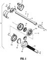
- system 10 may include an obturator assembly or optical access apparatus 11 and a cannula assembly 100 which is configured to at least partially receive the obturator assembly 11.
- the obturator assembly 11 includes an obturator housing 12 disposed in mechanical cooperation with an elongated obturator member or trocar 14, which defines a longitudinal axis "A-A.”
- the obturator member 14 extends distally from the obturator housing 12.
- obturator assembly and “optical access apparatus,” and the terms “obturator member,” “trocar” and “elongated obturator tubular member” are used interchangeably herein and are intended to include any or all of the mechanisms known in the art for separating tissue planes in a surgical procedure and for the blunt dissection of cavity linings and/or organs during a surgical procedure.
- the obturator member 14 includes an obturator shaft 18 mechanically engagable with the obturator housing 12.
- the obturator member 14 also includes an optical member or tunneling member 20 at the distal end of the obturator shaft 18.
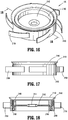
- the cannula assembly 100 of the surgical visualization system 10 includes a clear (i.e., transparent or translucent) elongated portion 102, defining a longitudinal axis "B-B," and a cover 110.
- the cover 110 encloses an insert seal assembly 130 and a zero-closure seal 150.
- the insert seal assembly 130 which is configured to provide a seal about a surgical instrument inserted therethrough, is disposed proximally of the zero-closure seal 150, which is configured to prevent gasses from proximally exiting cannula assembly 100 when in the absence of a surgical instrument inserted therethrough.
- cover 110 includes a proximal section 110a and a distal section 110b, which are selectively engageable with each other, as discussed below.
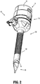
- a distal end of the optical access apparatus 11 may include a tunneling or optical member 20, at least a portion of which being translucent or transparent.
- tunneling or optical member 20 at least a portion of which being translucent or transparent.
- optical member optical member
- overmolded attachment are used interchangeably herein and are intended to include any or all of the mechanisms known in the art for blunt tip members utilized for attachment to obturator, trocar and cannula assemblies for separating tissue planes in a surgical procedure and for the blunt dissection of cavity linings and/or organs during a surgical procedure.
- optical member 20 may be substantially hollow to receive the distal end of an endoscope ( FIG. 6C ).
- a distal viewing tip of an endoscope may be brought into engagement with a sloped surface 201 within the optical member 20, as will be described hereinbelow.
- Improved optical characteristics of the system permit precise and accurate visual placement thereof into a body cavity. Accordingly, the access system may be suitable as an initial entry surgical access system.
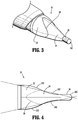
- the optical member 20 includes a proximal section 22, a central section 24, and an atraumatic guiding nub 26.
- An imaginary line 28 (shown to illustrate curvature) delineates the boundary between the proximal section 22 and the central section 24.
- the tunneling or optical member 20 is a bladeless tip configured for traversing and/or penetrating body tissue.
- the tunneling member 20 may be configured with for example, a sharp tip, a pointed tip, a pyramidal tip, a bladed tip, a conical tip, and/or a tip comprising one or more sharp edges or sharpened edges.
- the tunneling member 20 may be a radiused blunt tip, which may be helpful for traversing an existing body orifice, and/or relatively soft or fatty tissue.
- FIG. 4 illustrates a top view of the optical member 20.
- the proximal section 22 includes a pair of diametrically opposed convex surfaces 222
- the central section 24 includes a pair of diametrically opposed concave surfaces 242.
- the atraumatic guiding nub 26 extending distally from the central section 24, is generally cylindrical, and includes a rounded end 262.
- the rounded end 262 defines a radius of curvature dimensioned to be atraumatic to tissue.
- phantom lines that represent a cone a portion of both the proximal section 22 and the atraumatic guiding nub 26 of optical member 20 are outside of the dimensions of the cone.
- tunneling member 20 may include the atraumatic guiding nub 26 characterized by having a nipple configuration nose with a rounded tip.
- the atraumatic guiding nub or nose 26 may be generally tapered defining a simple curved arrangement.
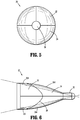
- an end or axial view of the optical member 20 illustrates the circular profile of the guiding nub 26, the oval profile of the central section 24, and the circular profile of the proximal section 22.
- FIG. 6 shows a side view of the optical member 20 radially offset 90° relative to the top view of FIG. 4 .
- the proximal section 22 of the optical member 20 further includes a pair of diametrically opposed outer surfaces 224 which are generally linear and/or convex.
- the central section 24 also includes a pair of opposed outer surfaces 244 which are convex.
- the central section 24 of the optical member 20 is inclusive of both concave surfaces 242 ( FIG. 4 ) and convex surfaces 244 ( FIG. 6 ) however, it is envisioned that the optical member 20 may include only one type of surface, either concave or convex (not shown). Alternatively, in embodiments, it is envisioned that rounded tip 226 may be more pointed than the embodiment illustrated.
- a portion of the proximal section 22, the central section 24, and the atraumatic guiding nub or tip 26 of optical member 20 are outside of the dimensions of the cone.
- the atraumatic guiding nub 26 permits initial insertion within an opening, e.g., a pre-cut scalpel incision, in the tissue and facilitates the advancement of the optical member 20 between the tissue layers to gently dissect tissue, e.g., without any cutting or incising of the tissue.
- an opening e.g., a pre-cut scalpel incision
- the central section 24 and the proximal portion 22 continue to gently enlarge the opening in tissue.
- FIG. 6A is a cross-sectional view of the optical member 20 taken at approximately the longitudinal midpoint thereof.
- the figure illustrates that the optical member 20 includes rounded outer surfaces 31 that function to help separate tissue along the tissue planes and minimize the potential of undesired or unintended piercing of tissue.
- the optical member 20 may be fabricated from a polymeric material and is transparent or translucent to permit passage of light rays.
- the optical member 20 is overmolded onto the obturator shaft 18 to connect the components.
- the obturator shaft 18 includes a distal shaft section which depends radially inwardly relative to the longitudinal axis A-A and includes at least one slot 207.
- the optical member 20 is molded to encapsulate the distal shaft section and is secured to the obturator shaft 18 by engaging the at least one slot upon curing of the polymeric material.
- the optical member 20 defines an internal chamfered or sloped surface 201 which is obliquely arranged relative to the longitudinal axis A-A.
- the chamfered surface 201 is able to be directly engaged by the outermost periphery of the distal end of the endoscope (see FIG. 6C ) such that light transmitted from regions of the endoscope radially within the outer periphery travel across an air gap prior to being received by the chamfered or sloped surface 201.
- the optical member 20 permits the passage of light rays to enable viewing (with the endoscope) tissue adjacent the optical member 20 during the insertion and/or advancement of the surgical visualization system 10.
- elongated tubular member 14 includes a first diameter "d" at a location 203 within a distal region 205.
- trocar 14 is configured for insertion through cannula assembly 100.
- cannula assemblies 100 typically vary in diameter (e.g., inner diameters of 11 mm, 12 mm, or 15 mm) depending on the surgical task to be performed, area of operation, preference of surgeon, etc.
- the obturator member 18 (of a trocar 14) having a corresponding diameter i.e., the outer diameter of the obturator member 18 is slightly smaller than the inner diameter of the cannula assembly 100
- obturator members 18 are typically manufactured with different diameters - one size obturator member 18 for each size cannula assembly 100.
- a single obturator member 18 (having one diameter "d" (notwithstanding the change in diameter at a distal portion 32 thereof, as discussed below) is configured for use with cannula assemblies 100 having different diameters.
- the optical member 20 is configured such that an outer surface 30 of its proximal portion 22 is dimensioned to provide a desired fit within the elongated portion 102 of cannula assembly 100. It is contemplated that a desired fit between trocar 14 and cannula 100 results in optical member 20 having little or no radial movement or "play" when inserted through cannula 100. More particularly, with reference to FIGS.
- distal portion 32 of obturator member 18 includes a radially outward flared portion 34, and optical member 20 is overmolded such that optical member 20 at least partially encapsulates flared portion 34.
- the thickness "t" of a wall 36 of optical member 20 is dimensioned to help ensure outer surface 30 of proximal portion 22 provides the desired fit between obturator member 11 and the elongated portion 102 of the cannula assembly 100.
- the obturator member 18 when a 15mm cannula is used, the obturator member 18 has an outer diameter slightly greater than 10 mm, and the widest portion (e.g., proximal portion 22) of the optical member 20 has an outer diameter slightly less than the inner diameter of the 15 mm cannula; when a 12mm cannula is used, obturator member 18 has an outer diameter slightly greater than 10 mm, and the widest portion of the optical member 20 has an outer diameter slightly less than the inner diameter of the 12 mm cannula; and when an 11mm cannula is used, the obturator member 18 has an outer diameter slightly greater than 10 mm, and the widest portion of the optical member 20 has an outer diameter slightly less than the inner diameter of the 11 mm cannula.
- a single diameter tube e.g., a 10 mm steel or polymeric tube
- obturator assemblies 11 for use with a variety of sizes (e.g., 11 mm, 12 mm and 15 mm) of cannula assemblies 100.
- manufacturing costs may be significantly reduced.
- the present disclosure also relates to a method of manufacturing surgical visualization systems 10, or components thereof.
- elongated tubular member 14 of the optical access apparatus 11 may be dimensioned and configured to receive therein any suitable endoscope ( FIG. 6C ) and/or laparoscope (not shown), which typically includes an imaging element and fiber optic light fibers (not illustrated).
- the endoscope may be positioned within optical access apparatus 11 and the assembled unit is advanced through an incision and into the body cavity. During the advancement within tissue, the endoscope permits constant visualization of the neighboring tissue thereby providing confirmation upon entering into the body cavity while also minimizing undesired contact or engagement with any underlying organs or other body tissues. Alternatively, in embodiments, the endoscope may be positioned within optical access apparatus 11 after the optical access apparatus 11 has been advanced into the body cavity.
- the endoscope may be any conventional scope suitable for endoscopic applications including, e.g., a laparoscope, arthroscope, colonoscope, etc.
- the endoscope may incorporate an optical train or lens arrangement which is capable of transmitting an image of an object from the distal or objective lens through the eyepiece or monitor for viewing by the surgeon.
- the endoscope may include an eyepiece at its proximal end, the endoscope additionally or alternatively may be connected to a monitor.
- the wall of the tunneling member 20 includes a thin-wall configuration.
- the thin-wall configuration enables light to travel through the material with reduced loss in intensity, thereby enhancing the visibility of tissue through the tunneling member 20 as the optical access apparatus 11 is advanced and placed into the targeted body cavity.
- the thin-wall configuration also reduces distortion of the image viewed through the tunneling member 20 and maintains the color accuracy of the viewed tissue.
- the wall thicknesses of tunneling member 20 may be from about 0.02 inches (about 0.5 mm) to about 0.025 inches (about 0.65 mm). In other embodiments, the tip wall may be thicker, for example, to provide additional strength.
- All transparent or translucent materials may have a light transmittance value of less than about 100%. That is, less than about 100% of the light incident on the material is transmitted directly through the material.
- a reduced wall thickness may reduce the loss of light or absorption thereby improving the image of the tissue through which the elongated tubular member 14 is advanced, and maintaining the color accuracy and fidelity of the observed tissue.
- the device may include a pair of vent holes (not shown) at the rounded end 262 of the optical access apparatus 11, through which an insufflating gas, such as carbon dioxide, flows into a body cavity, as discussed in greater detail below.
- an insufflating gas such as carbon dioxide
- the optical access apparatus 11 may be manufactured from any material known to those skilled in the art by any known molding techniques which is suitable for accessing body tissue.
- each of the components of the optical access apparatus 11 may include different materials.
- suitable materials may also include, for example, biocompatible metals such as stainless steel, titanium and the like, ceramics, silicones and the like.
- Some embodiments of the optical access apparatus 11 may further include a composite, for example, a fiber-reinforced polymer.
- a stronger material permits reducing a wall thickness of a component without reducing the strength thereof.
- some embodiments of a metal or composite elongated tubular member 14 are thinner than a corresponding polymer version, thereby increasing the diameter of a lumen thereof without increasing the outer diameter.
- elongated tubular member or obturator 14 may be transparent or translucent throughout its entire length. Alternatively, only tunneling member 20 of elongated tubular member 14 may be transparent or translucent.
- the elongated tubular member 14 may include a biocompatible metal material, for example, a stainless steel tube, and the tunneling member 20 may be a thermoplastic elastomeric, such as for example, LEXAN®, commercially available from SABIC Innovative Plastics Holding BV, insert molded onto the elongated tubular member.
- the metal tube may have a wall thickness as thin as about 0.003 inches (about 0.076 mm).
- the cannula 100 may include a rigid material.
- the obturator may include a rigid material and/or a flexible material because the obturator may be largely supported by the cannula during use.
- any suitable material for forming the tunneling member 20 as described above may be utilized.
- an elastomeric material may be configured to flow into the at least one slot or piercing 207 of the elongated tubular member 14.
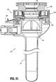
- the obturator housing 12 of the obturator assembly 11 includes an opening 160 ( FIG. 7 ) and a scope retention member 170 ( FIG. 8 ) adjacent the opening 160.
- scope retention member 170 is fabricated from an elastomeric material.
- Scope retention member 170 defines a central opening 172 for receiving the endoscope and includes four radial slits 174 extending outwardly from the central opening 172. The radial slits 174 permit flexure of the scope retention member 170 and enlargement of the central opening 172 upon insertion of the endoscope.
- the scope retention member 170 is adapted to engage the outer surface of the endoscope in frictional engagement therewith to assist in retaining the relative positioning of the endoscope within the obturator assembly 11.
- the cannula assembly 100 includes an elongated portion 102, defining a longitudinal axis "B-B," and a cover 110.
- the cover 110 which includes a proximal housing component 110a and a distal housing component 110b, encloses insert seal assembly 130 and a zero-closure seal 150.
- the insert seal assembly 130 is disposed proximally of the zero-closure seal 150. More particularly, proximal housing component 110a encloses insert seal assembly 130, and distal housing component 110b encloses zero-closure seal 150.
- the cover 110 is configured to mechanically engage a proximal portion of the elongated portion 102 and helps maintain the insert seal assembly 130 and the zero-closure seal 150 therein.
- Cover 110 also includes a pair of notches 126 ( FIG. 11 ) thereon. Notches 126 are configured to be mechanically engaged by a pair of latches 19 disposed on the obturator assembly 11 (see FIG. 1 ). The selective engagement between latches 19 and notches 126 enables a user to selectively lock and unlock the obturator assembly 11 to and from the cannula assembly 100.
- cover 110 includes a proximal housing component 110a and a distal housing component 110b.
- Proximal housing component 110a defines inner wall 1112 and outer wall 1114 disposed radially outwardly of the inner wall 1112.
- Inner wall 1112 defines central passage 1116 which is dimensioned to receive a surgical instrument.
- Outer wall 1114 defines first and second annular recesses 1120, 1122 adjacent its distal end. Recesses 1120, 1122 receive corresponding structure, e.g., annular lips 1124, 1126 of distal housing component 110b to facilitate connection of the two components.
- proximal housing component 110a may also incorporate locking tabs which engage corresponding structure of distal housing component 110b upon relative rotation of the components 110a, 110b to securely connect the components.
- a distal portion of outer wall 1114 of proximal housing component 110a includes a pair of ramps 1200, each of which being configured to engage a threaded portion 1300 (e.g., including male threads) and/or annular lips 1124, 1126 of distal housing component 110b.
- a threaded portion 1300 e.g., including male threads
- annular lips 1124, 1126 of distal housing component 110b are thereby affected through alignment and rotation of the components.
- proximal housing component 110a includes a stop 1210 adjacent each ramp 1200, which limits the rotational movement of distal housing component 110b with respect to proximal housing component 110a.
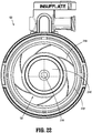
- the present disclosure includes a rotation prevention mechanism 1500.
- the rotation prevention mechanism 1500 is a mechanism that may prevent inadvertent relative rotation, and thus potential decoupling, of proximal housing component 110a and distal housing component 110b.
- the rotation prevention mechanism 1500 may include components that are integrally formed with one or both of the proximal housing component 110a and the distal housing component 110b. Additionally or alternatively, the rotation prevention mechanism 1500 may include components that are integrally formed with components that are fixedly connected to one or both of the proximal housing component 110a and the distal housing component 110b.
- FIGS. 9-14 provides an example of the rotation prevention mechanism 1500 which includes a first component that is integrally formed with the proximal housing component 110a and a second component that is fixedly connected to the distal housing component 110b.
- the rotation prevention mechanism 1500 includes components that are integrally formed with different components that are fixedly connected to either the proximal housing component 110a and the distal housing component 110b.
- the rotation prevention mechanism 1500 includes two components
- the rotation prevention mechanism 1500 includes only one component (e.g., a component that is part of or connected to a single one of the proximal housing component 110a and the distal housing component 110b), or includes more than two components (e.g., components that are part of or connected to other components in addition to the proximal housing component 110a and the distal housing component 110b).
- the rotation prevention mechanism 1500 which includes a first component 1502 and a second component 1508.
- the first component 1502 consists of a finger 1503 that is integrally formed with a circumferential edge of the proximal housing component 110a.
- the second component 1508 of the rotation prevention mechanism 1500 is a tab 1507 that is integrally formed with a circumferential edge of the distal housing component 110b.
- Tab 1507 includes a radially outward user-actuatable portion 1508 and a radially-inward locking portion 1509.
- the tab 1507 is configured for resilient movement relative to the distal housing component 110b about its point of attachment thereto, such that at least a portion of the tab 1507, e.g., the user-actuatable portion 1508, is moveable distally relative to the circumferential edge of the distal housing component 110b (see FIG. 21 , for example).
- proximal housing component 110a As the proximal housing component 110a is rotated in a first direction (e.g., clockwise when FIGS. 12 and 14 are viewed from above), a ramped surface 1504 of finger 1503 engages locking portion 1509 of tab 1507. Continued rotation of proximal housing component 110a causes finger 1503 to exert a force, e.g., a force directed in the radially outward direction, on locking portion 1509 of tab 1507. The radially outward force is sufficient to cause tab 1507 to move radially outward relative to the circumferential edge of the distal housing component 110b about its point of attachment thereto, from its first, biased position towards its second position.
- a force e.g., a force directed in the radially outward direction
- the radially outward force causes a portion, e.g., user actuatable portion 1508, of tab 1507 to move distally).
- the finger 1503 passes the tab 1507, and causes the locking portion 1509 tab 1507 to move back to its first, biased position and adjacent with a substantially perpendicular surface 1510 of finger 1503.
- proximal housing component 110a is effectively prevented from counter-clockwise rotation with respect to distal housing component 110b.
- proximal housing component 110a when sufficient rotation of proximal housing component 110a causes the finger 1503 to pass the tab 1507, a protrusion 1520 of the proximal housing component 110a contacts a stop 1522 of distal housing component 110b, thus effectively preventing additional clockwise rotation between the proximal housing component 110a and the distal housing component 110b. Accordingly, during the annular orientation of proximal housing component 110a and the distal housing component 110b that is illustrated in Figure 12 , both directions of rotation of the proximal housing component 110a are effectively prevented, and thus the proximal housing component 110a is rotationally fixed with respect to the distal housing component 110b.
- the rotation prevention mechanism 1500 automatically prevents the proximal housing component 110a from inadvertently rotating relative to, and thus inadvertently becoming disconnected from, the distal housing component 110b once the proximal housing component 110a reaches this locked position.
- the user may then exert a force, e.g., a force directed in the distal direction, on the tab 1507.
- a force e.g., a force directed in the distal direction
- This distally-directed force may be sufficient to cause the user actuatable portion 1508 the tab 1507 to move distally relative to the circumferential edge of the distal housing component 110b about its point of attachment thereto until the locking portion 1509 of tab 1507 is located radially outward of finger 1503.
- the proximal housing component 110a is no longer prevented from rotating, but rather is free to rotate, in a second direction (i.e., counter-clockwise when FIGS.
- the rotation prevention mechanism 1500 provides a selectively actuatable mechanism that, when actuated, enables a user to rotate and thereby disconnect proximal housing component 110a from distal housing component 110b. It is envisioned that upon or during removal of obturator assembly 11 from tissue, a user may desire to disconnect proximal housing component 110a from distal housing component 110b to allow the obturator assembly 11 to be fully removed from the elongated portion 102 of the cannula assembly 100 without coming out of engagement with the insert seal assembly 130, for example. Further details of the cover 110 and the rotation prevention mechanism 1500 are disclosed in U.S. Patent Application Serial No. 61/673,390, filed on July 19, 2012 , the entire contents of which being incorporated by reference herein.
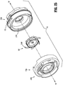
- the insert seal assembly 130 includes an elastomeric septum seal 2140, a lower seal support 2160 and an upper seal support 2180.
- Septum seal 2140 which is configured to provide a seal around the outer surface of an instrument passing therethrough, includes a flat seal portion 2142 having an orifice 2144 at or near its radial center, an annular wall 2146, and a peripheral seal 2148.
- Septum seal 2140 also includes a plurality of apertures 2150 annularly disposed on flat seal portion 2142 adjacent annular wall 2146.
- Lower seal support 2160 includes a substantially vertical collar portion 2162, a plurality of spring elements or spokes 2164 extending radially outwardly from collar portion 2162, a substantially horizontal or engagement surface 2166 extending radially inward from collar portion 2162, and an inner ring 2168 extending downwardly from an inner circumference of horizontal surface 2166.
- Horizontal surface 2166 includes a plurality of apertures 2170 annularly disposed therearound. When insert seal assembly 130 is assembled, apertures 2170 are longitudinally aligned with apertures 2150 of septum seal 2140.
- Upper seal support 2180 includes a ring-like, substantially horizontal surface 2182, an annular, substantially vertical wall 2184 depending downwardly from surface 2182, and a plurality of fingers 2186 extending downwardly from wall 2184.
- Fingers 2186, apertures 2150 of septum seal 2140, and apertures 2170 of lower seal support 2160 are longitudinally aligned, such that when insert seal assembly 130 is assembled, fingers 2186 extend through apertures 2150 of septum seal 2140 and through apertures 2170 of lower seal support 2160. Further, this engagement between fingers 2186, apertures 2150 of septum seal 2140, and apertures 2170 of lower seal support 2160 helps secure the three components together and helps prevent relative movement along and about the longitudinal axis B-B.
- insert seal assembly 130 is positioned within a portion of cover 110.
- insert seal assembly 130 is housed within proximal housing component 110a.
- insert seal assembly 130 is positioned between a first portion 2190 and a second portion 2192 of proximal housing component 110a, and is radially movable therein.
- First portion 2190 and second portion 2192 of proximal housing component 110a are selectively engageable with each other (e.g., via a snap-fit arrangement).
- at least one spoke 2164 is in contact with an inner wall 2191 of first portion 2190.
- Spokes 2164 are configured to help maintain orifice 2144 at or near the radial center within proximal housing component 110a, and to help prevent free lateral movement of septum seal 2140 within proximal housing component 110a. That is, spokes 2164 of lower seal support 2160 bias insert seal assembly 130 toward the radial center of proximal housing component 110a.
- the orifice 2144 of the septum seal 2140 which may otherwise move to an off-center location (as shown in FIG. 23 ), is urged toward the radial center of proximal housing component 110a, such that orifice 2144 is in a centered location for reception of a subsequently-inserted surgical instrument (e.g., a surgical stapling device).
- a subsequently-inserted surgical instrument e.g., a surgical stapling device
- the insert seal assembly 130' includes an elastomeric septum seal 2140', a return spring 2160', a lower seal retainer 2120', and an upper seal retainer 2180'.
- Septum seal 2140' which is configured to provide a seal around the outer surface of an instrument passing therethrough, includes a flat seal portion 2142' having an orifice 2144' at or near its radial center, an annular wall 2146', and a peripheral seal 2148'.
- Septum seal 2140' also includes a plurality of apertures 2150' annularly disposed on flat seal portion 2142' adjacent annular wall 2146'.
- the return spring 2160' includes a substantially vertical collar portion 2162' and a plurality of spring elements or spokes 2164' extending radially outwardly from the collar portion 2162'. Additionally, the return spring 2160' includes a plurality of spaced apart protrusions 2166' that extend from the vertical collar portion 2162' towards the center of the return spring 2160'. The plurality of spaced apart protrusions 2160' are sandwiched between the lower seal retainer 2120' and the upper seal retainer 2180', as shown in the assembled view of FIG. 28 .
- the return spring 2160' is more stable relative to the lower seal retainer 2120' and the upper seal retainer 2180' during use and less likely to be dislodged when the movement of an instrument within the aperture 2144' causes the insert seal assembly 130' to move within proximal housing component 110a.
- Upper seal support 2180' includes a ring-like, substantially horizontal surface 2182', an annular, substantially vertical wall 2184' depending downwardly from surface 2182', and a plurality of fingers 2186' extending downwardly from wall 2184'. Fingers 2186' and apertures 2150' of septum seal 2140' are longitudinally aligned, such that when insert seal assembly 130' is assembled, fingers 2186' extend through apertures 2150' of septum seal 2140'. Further, this engagement between fingers 2186' and apertures 2150' of septum seal 2140' assists in securing the two components together and helps prevent relative movement along and about the longitudinal axis B-B.
- each protrusion 2166' of return spring 2160' is located between corresponding fingers 2186' for limiting relative rotation between upper seal support 2180', septum seal 2140', and return spring 2160' (see FIG. 29 ).
- each finger 2186' frictionally engages a corresponding protrusion 2166' for securing the relative rotational positions between the return spring 2160', the septum seal 2140', and the upper seal support 2180'.
- insert seal assembly 130' is positioned within a portion of cover 110. Further details regarding positioning, use and function of insert seal assembly 130' are similar to the positioning, use and function of insert seal assembly 130, as discussed above. Additionally, and as can be appreciated, the apparatuses disclosed herein can include either insert seal assembly 130 or insert seal assembly 130'.
- the abdominal cavity is insufflated with a suitable biocompatible gas such as, e.g., CO 2 gas, to insufflate the body cavity and lift the body cavity wall away from the internal organs therein.
- a suitable biocompatible gas such as, e.g., CO 2 gas
- the insufflation may be performed with an insufflation needle or similar device as is conventional in the art.
- the system 10 may also be utilized in a space that has not been insufflated.
- an initial incision “I” is made in tissue "T" (e.g., skin) by a surgical instrument (e.g., a scalpel) (see FIG. 24 ).
- the incision "I” is preferably small, for example, within a range from about 2 mm to about 7 mm.
- the obturator assembly 11 of the surgical visualization system 10 is at least partially introduced within the cannula assembly 100 with the obturator member 14 extending through the aperture 2144 of the septum seal 2140 and through the zero-closure seal 150.
- the assembled unit is positioned within the initial incision and against the target tissue, e.g., the abdominal lining.
- an endoscope may be inserted through the obturator assembly 11 such that the distal viewing end of the endoscope is positioned against the chamfered surface of the optical member 20.
- the endoscope may be retained at this relative position within the obturator assembly 11 by the scope retention member 170.
- the optical member 20 is manipulated relative to the tissue whereby the atraumatic guiding nub 26 engages tissue and, in combination with the concave and/or convex outer surfaces 244, gently dissect or separate the tissue along a natural tissue plane to gain access to an underlying cavity in a non-traumatic fashion.
- the tissue adjacent the optical member 20 is viewed with the endoscope.
- the endoscope is utilized to view the path along which the system is advanced to ensure that any underlying tissue or organ site is prevented from contact with the obturator assembly 11 and also to confirm entry within the body cavity.
- the endoscope may be used to monitor the desired surgical procedure being performed within the cavity.
- the endoscope may be inserted into and secured in the obturator assembly 11 after the obturator assembly 11 has been positioned within tissue.
- the obturator assembly 11 may then be removed from the cannula assembly 100. Instruments may be introduced within the cannula assembly 100 to perform a surgical procedure.
Description
- The present disclosure relates to a visualization system and apparatus for tunneling through body tissue. More particularly, the present disclosure relates to an optical trocar which includes a transparent tunneling member which facilitates penetration of body tissue under direct observation.
- Endoscopic and laparoscopic minimally invasive procedures have been used for introducing medical devices inside a patient and for viewing portions of the patient's anatomy. Typically, to view a desired anatomical site, a surgeon may insert a rigid or flexible endoscope inside the patient to render images of the anatomical site. In endoscopic surgical procedures, surgery is performed in any hollow organ or tissue of the body through a small incision or through narrow endoscopic tubes (cannulas) inserted through a small entrance wound in the skin. In laparoscopic procedures, surgical operations in the abdomen are performed through small incisions (usually about 0.5 to about 1.5 cm). Laparoscopic and endoscopic procedures often require the surgeon to act on organs, tissues and vessels far removed from the incision, thereby requiring that any instruments used in such procedures be of sufficient size and length to permit remote operation.
- Typically, a trocar includes a cannula and a stylet or obturator. The cannula remains in place for use during the laparoscopic procedure, and the obturator includes a sharp tip for penetrating the body cavity. Most currently used trocars rely on protective tubes or relative retraction of the tip to prevent inadvertent contact with tissue.
- Accordingly, the present disclosure is directed to further improvements in laparoscopic or visualization instruments.
- The present disclosure relates to a surgical system comprising a first obturator assembly and a second obturator assembly. The first obturator assembly includes a first obturator member and a first optical member. The first optical member is disposed adjacent a distal portion of the first obturator member. The first obturator member has a first diameter. A proximal portion of the first optical member has a second diameter. The second diameter is greater than or equal to the first diameter. The second obturator assembly includes a second obturator member and a second optical member. The second optical member is disposed adjacent a distal portion of the second obturator member. The second obturator member has a third diameter. The third diameter is equal to the first diameter. A proximal portion of the second optical member has a fourth diameter. The fourth diameter is different from the second diameter.
- In disclosed embodiments, the surgical system further comprises a first cannula assembly. An inner diameter of an elongated portion of the first cannula assembly approximates the second diameter. Here, it is disclosed that the surgical system further comprises a second cannula assembly. An inner diameter of an elongated portion of the second cannula assembly approximates the fourth diameter. The inner diameter of the elongated portion of the second cannula assembly is different from the inner diameter of the elongated portion of the first cannula assembly.
- In disclosed embodiments, the surgical system further comprises a third obturator assembly including a third obturator member and a third optical member disposed adjacent a distal portion of the third obturator member. The third obturator member has a fifth diameter, which is equal to the first diameter. A proximal portion of the third optical member has a sixth diameter, which is different from the second diameter and the fourth diameter.
- In disclosed embodiments, the first diameter and the third diameter are each about 10 mm. Here, it is envisioned that second diameter is about 14 mm, and that the fourth diameter is about 10 mm.
- In disclosed embodiments, a distal portion of the first obturator member includes a radially outward flared portion.
- In disclosed embodiments, a distal portion of the first obturator member is encapsulated by the first optical member.
- The present disclosure also relates to a method of manufacturing a plurality of obturator assemblies. The method comprises providing a tube including a first diameter, providing a first obturator member including a portion of the tube, providing a second obturator member including a portion of the tube, providing a first optical member having a second diameter, and providing a second optical member having a third diameter, which is different from the second diameter. The method also comprises engaging the first obturator member and the first optical member, and engaging the second obturator member and the second optical member.
- In disclosed embodiments, engaging the first obturator member and the first optical member includes overmolding the first optical member onto the first obturator member.
- In disclosed embodiments, the first diameter is about 10 mm. It is further disclosed that the second diameter is about 14 mm. It is further disclosed that the third diameter is about 10 mm.
- In disclosed embodiments, the tube is made from at least one of steel and a polymeric material.
- In disclosed embodiments, a distal portion of the first obturator member includes a radially outward flared portion.
- In disclosed embodiments, a distal portion of the first obturator member is encapsulated by the first optical member.
- In disclosed embodiments, the method further comprises providing a third obturator member including a portion of the tube, providing a third optical member having a fourth diameter, which is different from the second diameter and the third diameter, and engaging the third obturator member and the third optical member.
- The present disclosure also relates to a surgical access device comprising an obturator assembly and a cannula assembly. The obturator assembly comprises an obturator member and a tip member disposed adjacent a distal portion of the obturator member. The obturator member has an outer diameter of about 10 mm. A portion of the tip member has an outer diameter of between about 14 mm and about 15 mm. The cannula assembly comprises an elongated portion configured to allow the obturator member and the tip member to slide therethrough. An inner diameter of the elongated portion approximates the outer diameter of the tip member.
- The present disclosure also relates to a seal assembly for use with a surgical instrument. The seal assembly comprises a housing, a septum seal, a lower seal support, an upper seal support, and a return spring. The septum seal is disposed within the housing and includes an orifice and a plurality of apertures. The orifice is configured for providing a seal about a portion of an instrument inserted therethrough. The lower seal support includes an engagement surface. The engagement surface is configured to engage a portion of the septum seal. The engagement surface includes a plurality of apertures extending therethrough. The upper seal support includes a plurality of fingers, wherein each of the plurality of fingers is configured to extend through a corresponding aperture of the septum seal. The return spring includes a collar portion and a plurality of spokes extending radially outward from the collar portion. At least a portion of the return spring, e.g., a plurality of spaced apart radially inwardly extending protrusions, may be sandwiched between the lower seal support and the upper seal support. The plurality of spokes is configured to bias the seal assembly toward a radial center of a housing.
- In disclosed embodiments, the septum seal includes a flat surface and an annular wall extending perpendicularly from a radial outer edge of the flat surface. Here, it is disclosed that the annular wall of the septum seal includes a lower portion in contact with the flat surface and an upper portion extending from the flat surface, and that the upper portion includes a peripheral seal in mechanical engagement therewith. Here, it is further disclosed that the peripheral seal extends radially outward from the upper portion of the annular wall.
- In disclosed embodiments, the collar portion of the return spring is configured to be received at least partially within an annular channel of the lower seal support. It is also disclosed that the annular collar of the return spring is configured to engage the annular wall of the septum seal. Here, it is disclosed that the peripheral seal of the septum seal is configured to extend proximally of and in contact with a proximal edge of the annular collar of the return spring. Here, it is further disclosed that the entirety of the septum seal comprises an elastomeric material, and that the entirety of the septum seal comprises the same material. It is further disclosed that the return spring further includes a plurality of protrusions extending radially inward from the collar portion, and that each protrusion cooperates with corresponding fingers of the upper seal support for controlling rotational movement between the return spring and the septum seal.
- The present disclosure also relates to a cannula assembly comprising a housing, an elongated portion extending distally from the housing and defining a longitudinal axis, and a seal assembly disposed at least partially within the housing. The seal assembly includes a septum seal, a lower seal support, an upper seal support, and a return spring. The septum seal includes an orifice and a plurality of apertures. The orifice is configured for providing a seal about a portion of an instrument inserted therethrough. The lower seal support includes an engagement surface. The engagement surface is configured to engage a portion of the septum seal. The engagement surface includes a plurality of apertures extending therethrough. The upper seal support includes a plurality of fingers, where each of the plurality of fingers is configured to extend through a corresponding aperture of the septum seal. The return spring includes a collar portion and a plurality of spokes extending radially outward from the collar portion. The return spring is configured to be received at least partially within a portion of the lower seal support. The plurality of spokes is configured to bias the seal assembly toward a radial center of the housing.
- In disclosed embodiments, the septum seal includes a flat surface and an annular wall extending perpendicularly from a radial outer edge of the flat surface. Here, it is disclosed that the annular wall of the septum seal includes a lower portion in contact with the flat surface and an upper portion extending from the flat surface, and where the upper portion includes peripheral seal in mechanical engagement therewith. Here, it is further disclosed that the peripheral seal extends radially outward from the upper portion of the annular wall.
- In disclosed embodiments, the collar portion of the return spring is configured to be received at least partially within an annular channel of the lower seal support. It is also disclosed that the annular collar of the return spring is configured to engage the annular wall of the septum seal. Here, it is disclosed that the peripheral seal of the septum seal is configured to extend proximally of and in contact with a proximal edge of the annular collar of the return spring. It is further disclosed that the return spring further includes a plurality of protrusions extending radially inward from the collar portion, and that each protrusion cooperates with corresponding fingers of the upper seal support for controlling rotational movement between the return spring and the septum seal.
- In disclosed embodiments, at least a portion of at least one spoke contacts an interior wall of the housing.
- In disclosed embodiments, the entirety of the septum seal is made from an elastomeric material.
- The present disclosure relates to a cannula assembly comprising a housing and an elongated portion extending distally from the housing. The housing comprises a proximal housing component, a distal housing component, and a rotation prevention mechanism. The distal housing component is rotatably connectable to the proximal housing component. The rotation prevention mechanism is configured to prevent inadvertent relative rotation between the proximal housing component and the distal housing component. The rotation prevention mechanism is configured for selective actuation by a user, such that, when actuated, the proximal housing component is permitted to rotate with respect to and be disconnectable from the distal housing component.
- In disclosed embodiments, the cannula assembly further comprises a seal disposed at least partially within the housing. Here, it is disclosed that the seal is accessible to a user when the proximal housing component and the distal housing component are disconnected from each other.
- In disclosed embodiments, the rotation prevention mechanism includes a first component disposed on the proximal housing component, and a second component disposed on the distal housing component. Here, it is disclosed that the first component of the rotation prevention mechanism includes a finger that is integrally formed on a circumferential edge of the proximal housing component. Here, it is disclosed that the second component of the rotation prevention mechanism includes a tab. A user actuatable portion of the tab is pivotable with respect to the distal housing component between a first position and a second position. Here, it is further disclosed that a locking portion of the tab is moveable into and out of engagement with the finger upon pivoting the user actuatable portion of the tab between its first position and its second position, and where engagement between the locking portion of the tab and the finger prevents one or two directions of rotation between the proximal housing component and the distal housing component.
- In disclosed embodiments, at least a portion of the tab is distally pivotable with respect to the distal housing component.
- In disclosed embodiments, after engagement between the proximal housing component and the distal housing component, a predetermined amount of rotation of the proximal housing component with respect to the distal component causes the proximal housing component to be locked in one direction of rotation with respect to the distal housing component.
- In disclosed embodiments, after engagement between the proximal housing component and the distal housing component, a predetermined amount of rotation of the proximal housing component with respect to the distal component causes the proximal housing component to be locked in both directions of rotation with respect to the distal housing component.
- The above and other aspects, features, and advantages of the present disclosure will become more apparent in light of the following detailed description when taken in conjunction with the accompanying drawings in which:
-
FIG. 1 is a perspective view with parts separated of a surgical visualization system in accordance with embodiments of the present disclosure illustrating the optical access apparatus and a cannula assembly; -
FIG. 2 is a perspective view of the surgical visualization system in accordance with the embodiment ofFIG. 1 ; -
FIG. 3 is an enlarged perspective view of the tunneling or optical member end of the access member of the optical access apparatus in accordance with the embodiment ofFIGS. 1-2 ; -
FIG. 4 is a top view of the optical member end ofFIG. 1 ; -
FIG. 5 is an axial view of the optical member ofFIG. 3 ; -
FIG. 6 is a side view of the optical member end radially offset 90° relative to the top view ofFIG. 4 ; -
FIG. 6A is a cross sectional view of the optical member ofFIG. 6 taken at approximately the longitudinal midpoint thereof; -
FIG. 6B is a cross sectional view of the elongated tubular member distal end region and optical member of the optical access apparatus ofFIG. 1 ; -
FIG. 6C is a cross sectional view of the elongated tubular member distal end region and optical member of the optical access apparatus ofFIG. 6B with an endoscope positioned therein; -
FIG. 7 is a perspective view of a cover and the cannula assembly ofFIG. 1 ; -
FIG. 8 is a perspective view of the cover of the cannula assembly ofFIG. 1 ; -
FIG. 9 is a perspective view of the cannula assembly showing a proximal housing component separated from a distal housing component; -
FIG. 10 is a perspective view of the distal housing component viewed from the proximal side; -
FIG. 11 is a perspective view of the proximal housing component; -
FIG. 12 is a cut-away perspective view taken along line 12-12 inFIG. 20 ; -
FIG. 13 is a cut-away perspective view taken along line 13-13 inFIG. 20 ; -
FIG. 14 is a cross-sectional view of a portion of the cannula assembly illustrating a portion of the proximal housing component engaging a portion of the distal housing component; -
FIG. 15 is a perspective, assembly view of the seal assembly and a portion of the housing; -
FIG. 16 is a perspective view of the seal assembly; -
FIG. 17 is a side view of the seal assembly; -
FIG. 18 is a cross-sectional view of the seal assembly taken along line 18-18 inFIG. 16 ; -
FIG. 19 is a perspective view with parts separated of the seal assembly; -
FIG. 20 is a cross-sectional view of the cannula assembly illustrating the tab in a first position; -
FIG. 21 is a cross-sectional view of the cannula assembly illustrating the tab in a second position; -
FIG. 22 is a cross-sectional view of a portion of the cannula assembly illustrating the seal assembly radially centered within the housing; -
FIG. 23 is a cross-sectional view of a portion of the cannula assembly illustrating an instrument inserted through the seal assembly, and the seal assembly being radially offset within the housing; -
FIG. 24 is a perspective view illustrating an endoscope positioned within the optical access apparatus and accessing body tissue; -
FIG. 25 is a perspective, assembly view of a seal assembly and a portion of the housing in accordance with embodiments of the present disclosure; -
FIG. 26 is a perspective view of the seal assembly ofFIG. 25 ; -
FIG. 27 is a side view of the seal assembly ofFIG. 25 ; -
FIG. 28 is a cross-sectional view of the seal assembly ofFIG. 25 taken along line 28-28 inFIG. 26 ; and -
FIG. 29 is a perspective view with parts separated of the seal assembly ofFIG. 25 . - Particular embodiments of the present disclosure are described hereinbelow with reference to the accompanying drawings; however, it is to be understood that the disclosed embodiments are merely exemplary of the disclosure and may be embodied in various forms. Well-known functions or constructions are not described in detail to avoid obscuring the present disclosure in unnecessary detail. Therefore, specific structural and functional details disclosed herein are not to be interpreted as limiting, but merely as a basis for the claims and as a representative basis for teaching one skilled in the art to variously employ the present disclosure in virtually any appropriately detailed structure. Like reference numerals refer to similar or identical elements throughout the description of the figures.
- As used herein, the term "distal" refers to that portion of the instrument, or component thereof which is farther from the user while the term "proximal" refers to that portion of the instrument or component thereof which is closer to the user.
- Various embodiments of the surgical visualization device and system disclosed herein may be employed in endoscopic, laparoscopic, open surgical procedures, interventional and/or intralumenal procedures such as GI sheathing (metabolic/bariatric) and/or banding, and/or for more advanced minimally invasive procedures such as those which employ a device that facilitates multiple instrument access through a single opening and permits a user to operate through a single entry point, i.e., navel, vagina and/or anus, where additional visualization due to compromising space, is required. In addition, the system of the present disclosure may be utilized for post-operative monitoring, diagnostics and combinations thereof.
- In embodiments, the visualization apparatus and system of the present disclosure may be utilized in lieu of or in addition to a traditional scope and/or surgical instrument, and the apparatus may be specifically designed for use with instruments including an endoscope and additional instruments such as graspers, staplers, forceps or the like introduced within a portal member to carry out the surgical procedure, and/or other access devices. An example of such a surgical portal is disclosed in
U.S. Patent Application Publication No. 2009/0093752 A1, filed October 2, 2008 . Additionally,U.S. Provisional Patent Application Serial No. 61/548,428 filed on October 18, 2011 - In embodiments, the device may be used to guide other instruments by sight or electronically to very precise anatomical sites, such as for example tumor and/or disease sites. In embodiments, for example, the apparatus may be utilized for complex thoracic surgeries where the apparatus may be positioned at the chest wall or lung directly for added visualization of critical vessels and/or pulmonary structures.
- Various embodiments of the visualization apparatus of the present disclosure may comprise devices inserted in a patient to provide visualization of the target site. These devices may be introduced into the patient using minimally invasive procedures through natural orifices such as those mentioned above, or via a device inserted through a trocar, for example, and may be adapted to provide images of the surgical site or anatomic location such as the lungs, liver, stomach, gall bladder, urinary tract, reproductive tract, and intestinal tissue, for example. Once positioned at the target site, the surgical visualization devices provide images that enable the surgeon to more accurately diagnose and provide more effective treatment of the diseased tissue. In embodiments, the visualization apparatus may be inserted into the tissue treatment region percutaneously. In other embodiments, the surgical visualization device may be introduced into the tissue treatment region endoscopically (e.g., laparoscopically and/or thoracoscopically), through small keyhole incisions via a trocar, or through a natural orifice.
- Embodiments of the surgical visualization devices may provide images of the desired tissue during in-vivo treatment procedures used to ablate or destroy live cancerous tissue, tumors, masses, lesions, and other abnormal tissue growths present at the tissue treatment site.
- In embodiments, a bladeless optical access system may be provided that permits separation of tissue planes in a surgical procedure and visualization of body tissue fibers as they are being separated, thereby permitting a controlled traversal across a body wall. In embodiments, a bladeless trocar may be provided that enables insufflation of a body cavity and contemporaneous visualization thereof through the distal tip of an obturator. In embodiments, the bladeless trocar or obturator may be provided for the blunt dissection of the abdominal lining during a surgical procedure.
- Referring now to
FIGS. 1 and2 , there is illustrated asurgical visualization system 10 in accordance with the present disclosure. In embodiments,system 10 may include an obturator assembly oroptical access apparatus 11 and acannula assembly 100 which is configured to at least partially receive theobturator assembly 11. Theobturator assembly 11 includes anobturator housing 12 disposed in mechanical cooperation with an elongated obturator member ortrocar 14, which defines a longitudinal axis "A-A." Theobturator member 14 extends distally from theobturator housing 12. The terms "obturator assembly" and "optical access apparatus," and the terms "obturator member," "trocar" and "elongated obturator tubular member" are used interchangeably herein and are intended to include any or all of the mechanisms known in the art for separating tissue planes in a surgical procedure and for the blunt dissection of cavity linings and/or organs during a surgical procedure. - The
obturator member 14 includes anobturator shaft 18 mechanically engagable with theobturator housing 12. Theobturator member 14 also includes an optical member or tunnelingmember 20 at the distal end of theobturator shaft 18. - The
cannula assembly 100 of thesurgical visualization system 10 includes a clear (i.e., transparent or translucent)elongated portion 102, defining a longitudinal axis "B-B," and acover 110. Thecover 110 encloses aninsert seal assembly 130 and a zero-closure seal 150. Theinsert seal assembly 130, which is configured to provide a seal about a surgical instrument inserted therethrough, is disposed proximally of the zero-closure seal 150, which is configured to prevent gasses from proximally exitingcannula assembly 100 when in the absence of a surgical instrument inserted therethrough. More particularly,cover 110 includes aproximal section 110a and adistal section 110b, which are selectively engageable with each other, as discussed below. - In embodiments, a distal end of the
optical access apparatus 11 may include a tunneling oroptical member 20, at least a portion of which being translucent or transparent. The terms "tunneling member," "optical member" and "overmolded attachment" are used interchangeably herein and are intended to include any or all of the mechanisms known in the art for blunt tip members utilized for attachment to obturator, trocar and cannula assemblies for separating tissue planes in a surgical procedure and for the blunt dissection of cavity linings and/or organs during a surgical procedure. - With particular reference to
FIGS. 3-6C ,optical member 20 may be substantially hollow to receive the distal end of an endoscope (FIG. 6C ). A distal viewing tip of an endoscope may be brought into engagement with asloped surface 201 within theoptical member 20, as will be described hereinbelow. Improved optical characteristics of the system permit precise and accurate visual placement thereof into a body cavity. Accordingly, the access system may be suitable as an initial entry surgical access system. - With reference to
FIGS. 3 and 4 , theoptical member 20 includes aproximal section 22, acentral section 24, and anatraumatic guiding nub 26. An imaginary line 28 (shown to illustrate curvature) delineates the boundary between theproximal section 22 and thecentral section 24. - In embodiments, the tunneling or
optical member 20 is a bladeless tip configured for traversing and/or penetrating body tissue. In other embodiments, the tunnelingmember 20 may be configured with for example, a sharp tip, a pointed tip, a pyramidal tip, a bladed tip, a conical tip, and/or a tip comprising one or more sharp edges or sharpened edges. In still other embodiments, the tunnelingmember 20 may be a radiused blunt tip, which may be helpful for traversing an existing body orifice, and/or relatively soft or fatty tissue. -
FIG. 4 illustrates a top view of theoptical member 20. As depicted, theproximal section 22 includes a pair of diametrically opposedconvex surfaces 222, and thecentral section 24 includes a pair of diametrically opposedconcave surfaces 242. The atraumatic guiding nub 26 extending distally from thecentral section 24, is generally cylindrical, and includes arounded end 262. Therounded end 262 defines a radius of curvature dimensioned to be atraumatic to tissue. Additionally, as shown in connection with phantom lines that represent a cone, a portion of both theproximal section 22 and the atraumatic guiding nub 26 ofoptical member 20 are outside of the dimensions of the cone. - In embodiments, tunneling
member 20 may include the atraumatic guiding nub 26 characterized by having a nipple configuration nose with a rounded tip. In embodiments, the atraumatic guiding nub ornose 26 may be generally tapered defining a simple curved arrangement. - With reference to
FIG. 5 , an end or axial view of theoptical member 20 illustrates the circular profile of the guidingnub 26, the oval profile of thecentral section 24, and the circular profile of theproximal section 22. -
FIG. 6 shows a side view of theoptical member 20 radially offset 90° relative to the top view ofFIG. 4 . As shown, theproximal section 22 of theoptical member 20 further includes a pair of diametrically opposedouter surfaces 224 which are generally linear and/or convex. Thecentral section 24 also includes a pair of opposedouter surfaces 244 which are convex. Thus, in embodiments, thecentral section 24 of theoptical member 20 is inclusive of both concave surfaces 242 (FIG. 4 ) and convex surfaces 244 (FIG. 6 ) however, it is envisioned that theoptical member 20 may include only one type of surface, either concave or convex (not shown). Alternatively, in embodiments, it is envisioned that rounded tip 226 may be more pointed than the embodiment illustrated. - Additionally, as shown in connection with the phantom lines in
Figure 6 that represent a cone, a portion of theproximal section 22, thecentral section 24, and the atraumatic guiding nub ortip 26 ofoptical member 20 are outside of the dimensions of the cone. - The atraumatic guiding nub 26 permits initial insertion within an opening, e.g., a pre-cut scalpel incision, in the tissue and facilitates the advancement of the
optical member 20 between the tissue layers to gently dissect tissue, e.g., without any cutting or incising of the tissue. After initial insertion and continued distal insertion, thecentral section 24 and theproximal portion 22 continue to gently enlarge the opening in tissue. -
FIG. 6A is a cross-sectional view of theoptical member 20 taken at approximately the longitudinal midpoint thereof. The figure illustrates that theoptical member 20 includes roundedouter surfaces 31 that function to help separate tissue along the tissue planes and minimize the potential of undesired or unintended piercing of tissue. - With reference to
FIGS. 6B and 6C , theoptical member 20 may be fabricated from a polymeric material and is transparent or translucent to permit passage of light rays. During assembly, theoptical member 20 is overmolded onto theobturator shaft 18 to connect the components. In particular, theobturator shaft 18 includes a distal shaft section which depends radially inwardly relative to the longitudinal axis A-A and includes at least oneslot 207. Theoptical member 20 is molded to encapsulate the distal shaft section and is secured to theobturator shaft 18 by engaging the at least one slot upon curing of the polymeric material. - In embodiments, the
optical member 20 defines an internal chamfered or slopedsurface 201 which is obliquely arranged relative to the longitudinal axis A-A. The chamferedsurface 201 is able to be directly engaged by the outermost periphery of the distal end of the endoscope (seeFIG. 6C ) such that light transmitted from regions of the endoscope radially within the outer periphery travel across an air gap prior to being received by the chamfered or slopedsurface 201. Theoptical member 20 permits the passage of light rays to enable viewing (with the endoscope) tissue adjacent theoptical member 20 during the insertion and/or advancement of thesurgical visualization system 10. - In embodiments,
elongated tubular member 14 includes a first diameter "d" at alocation 203 within adistal region 205. - Additionally, as discussed above,
trocar 14 is configured for insertion throughcannula assembly 100. Further,cannula assemblies 100 typically vary in diameter (e.g., inner diameters of 11 mm, 12 mm, or 15 mm) depending on the surgical task to be performed, area of operation, preference of surgeon, etc. Typically, once acannula assembly 100 having a particular diameter is selected, the obturator member 18 (of a trocar 14) having a corresponding diameter (i.e., the outer diameter of theobturator member 18 is slightly smaller than the inner diameter of the cannula assembly 100) is likewise chosen. That is,obturator members 18 are typically manufactured with different diameters - onesize obturator member 18 for eachsize cannula assembly 100. - In embodiments of the present disclosure, a single obturator member 18 (having one diameter "d" (notwithstanding the change in diameter at a
distal portion 32 thereof, as discussed below) is configured for use withcannula assemblies 100 having different diameters. Here, theoptical member 20 is configured such that anouter surface 30 of itsproximal portion 22 is dimensioned to provide a desired fit within theelongated portion 102 ofcannula assembly 100. It is contemplated that a desired fit betweentrocar 14 andcannula 100 results inoptical member 20 having little or no radial movement or "play" when inserted throughcannula 100. More particularly, with reference toFIGS. 6B and 6C ,distal portion 32 ofobturator member 18 includes a radially outward flaredportion 34, andoptical member 20 is overmolded such thatoptical member 20 at least partially encapsulates flaredportion 34. Further, the thickness "t" of awall 36 ofoptical member 20 is dimensioned to help ensureouter surface 30 ofproximal portion 22 provides the desired fit betweenobturator member 11 and theelongated portion 102 of thecannula assembly 100. - For example, when a 15mm cannula is used, the
obturator member 18 has an outer diameter slightly greater than 10 mm, and the widest portion (e.g., proximal portion 22) of theoptical member 20 has an outer diameter slightly less than the inner diameter of the 15 mm cannula; when a 12mm cannula is used,obturator member 18 has an outer diameter slightly greater than 10 mm, and the widest portion of theoptical member 20 has an outer diameter slightly less than the inner diameter of the 12 mm cannula; and when an 11mm cannula is used, theobturator member 18 has an outer diameter slightly greater than 10 mm, and the widest portion of theoptical member 20 has an outer diameter slightly less than the inner diameter of the 11 mm cannula. Thus, as can be appreciated, a single diameter tube (e.g., a 10 mm steel or polymeric tube) may be used for manufacturingseveral obturator assemblies 11 for use with a variety of sizes (e.g., 11 mm, 12 mm and 15 mm) ofcannula assemblies 100. As a result, manufacturing costs may be significantly reduced. The present disclosure also relates to a method of manufacturingsurgical visualization systems 10, or components thereof. - As mentioned above,
elongated tubular member 14 of theoptical access apparatus 11 may be dimensioned and configured to receive therein any suitable endoscope (FIG. 6C ) and/or laparoscope (not shown), which typically includes an imaging element and fiber optic light fibers (not illustrated). - The endoscope may be positioned within
optical access apparatus 11 and the assembled unit is advanced through an incision and into the body cavity. During the advancement within tissue, the endoscope permits constant visualization of the neighboring tissue thereby providing confirmation upon entering into the body cavity while also minimizing undesired contact or engagement with any underlying organs or other body tissues. Alternatively, in embodiments, the endoscope may be positioned withinoptical access apparatus 11 after theoptical access apparatus 11 has been advanced into the body cavity. - The endoscope may be any conventional scope suitable for endoscopic applications including, e.g., a laparoscope, arthroscope, colonoscope, etc. The endoscope may incorporate an optical train or lens arrangement which is capable of transmitting an image of an object from the distal or objective lens through the eyepiece or monitor for viewing by the surgeon. Thus, although the endoscope may include an eyepiece at its proximal end, the endoscope additionally or alternatively may be connected to a monitor.
- In embodiments, at least a portion of the wall of the tunneling
member 20 includes a thin-wall configuration. The thin-wall configuration enables light to travel through the material with reduced loss in intensity, thereby enhancing the visibility of tissue through the tunnelingmember 20 as theoptical access apparatus 11 is advanced and placed into the targeted body cavity. The thin-wall configuration also reduces distortion of the image viewed through the tunnelingmember 20 and maintains the color accuracy of the viewed tissue. In embodiments, the wall thicknesses of tunnelingmember 20 may be from about 0.02 inches (about 0.5 mm) to about 0.025 inches (about 0.65 mm). In other embodiments, the tip wall may be thicker, for example, to provide additional strength. - All transparent or translucent materials may have a light transmittance value of less than about 100%. That is, less than about 100% of the light incident on the material is transmitted directly through the material. For a given transparent or translucent material, as the wall thickness of the material increases, the amount of light that travels through the material decreases. In embodiments, a reduced wall thickness may reduce the loss of light or absorption thereby improving the image of the tissue through which the
elongated tubular member 14 is advanced, and maintaining the color accuracy and fidelity of the observed tissue. - The device may include a pair of vent holes (not shown) at the
rounded end 262 of theoptical access apparatus 11, through which an insufflating gas, such as carbon dioxide, flows into a body cavity, as discussed in greater detail below. - The
optical access apparatus 11 may be manufactured from any material known to those skilled in the art by any known molding techniques which is suitable for accessing body tissue. In embodiments, each of the components of theoptical access apparatus 11 may include different materials. In embodiments, suitable materials may also include, for example, biocompatible metals such as stainless steel, titanium and the like, ceramics, silicones and the like. Some embodiments of theoptical access apparatus 11 may further include a composite, for example, a fiber-reinforced polymer. In some embodiments, a stronger material permits reducing a wall thickness of a component without reducing the strength thereof. For example, some embodiments of a metal or composite elongatedtubular member 14 are thinner than a corresponding polymer version, thereby increasing the diameter of a lumen thereof without increasing the outer diameter. In embodiments, elongated tubular member orobturator 14 may be transparent or translucent throughout its entire length. Alternatively, only tunnelingmember 20 of elongatedtubular member 14 may be transparent or translucent. - In embodiments, the
elongated tubular member 14 may include a biocompatible metal material, for example, a stainless steel tube, and the tunnelingmember 20 may be a thermoplastic elastomeric, such as for example, LEXAN®, commercially available from SABIC Innovative Plastics Holding BV, insert molded onto the elongated tubular member. In embodiments, the metal tube may have a wall thickness as thin as about 0.003 inches (about 0.076 mm). - In embodiments, the
cannula 100 may include a rigid material. In embodiments, the obturator may include a rigid material and/or a flexible material because the obturator may be largely supported by the cannula during use. - The method of forming or overmolding the tunneling
member 20 to thedistal region 205 of theelongated tubular member 14 will now be discussed. In embodiments, any suitable material for forming the tunnelingmember 20 as described above may be utilized. In embodiments, an elastomeric material may be configured to flow into the at least one slot or piercing 207 of theelongated tubular member 14. - The
obturator housing 12 will now be discussed in more detail with reference toFIGS. 7 and 8 . Theobturator housing 12 of theobturator assembly 11 includes an opening 160 (FIG. 7 ) and a scope retention member 170 (FIG. 8 ) adjacent theopening 160. It is envisioned thatscope retention member 170 is fabricated from an elastomeric material.Scope retention member 170 defines acentral opening 172 for receiving the endoscope and includes fourradial slits 174 extending outwardly from thecentral opening 172. The radial slits 174 permit flexure of thescope retention member 170 and enlargement of thecentral opening 172 upon insertion of the endoscope. Thescope retention member 170 is adapted to engage the outer surface of the endoscope in frictional engagement therewith to assist in retaining the relative positioning of the endoscope within theobturator assembly 11. - The
cannula assembly 100 will now be discussed in detail with reference toFIGS. 9-14 . As mentioned above, thecannula assembly 100 includes anelongated portion 102, defining a longitudinal axis "B-B," and acover 110. Thecover 110, which includes aproximal housing component 110a and adistal housing component 110b, enclosesinsert seal assembly 130 and a zero-closure seal 150. Theinsert seal assembly 130 is disposed proximally of the zero-closure seal 150. More particularly,proximal housing component 110a enclosesinsert seal assembly 130, anddistal housing component 110b encloses zero-closure seal 150. - The
cover 110 is configured to mechanically engage a proximal portion of theelongated portion 102 and helps maintain theinsert seal assembly 130 and the zero-closure seal 150 therein. Cover 110 also includes a pair of notches 126 (FIG. 11 ) thereon.Notches 126 are configured to be mechanically engaged by a pair oflatches 19 disposed on the obturator assembly 11 (seeFIG. 1 ). The selective engagement betweenlatches 19 andnotches 126 enables a user to selectively lock and unlock theobturator assembly 11 to and from thecannula assembly 100. - With further regard to cover 110,
Figures 9-14 further illustrate the features of two-piece cover 110. As discussed above,cover 110 includes aproximal housing component 110a and adistal housing component 110b.Proximal housing component 110a definesinner wall 1112 andouter wall 1114 disposed radially outwardly of theinner wall 1112.Inner wall 1112 definescentral passage 1116 which is dimensioned to receive a surgical instrument. -
Outer wall 1114 defines first and secondannular recesses Recesses annular lips distal housing component 110b to facilitate connection of the two components. As can be appreciated,proximal housing component 110a may also incorporate locking tabs which engage corresponding structure ofdistal housing component 110b upon relative rotation of thecomponents - More particularly, a distal portion of
outer wall 1114 ofproximal housing component 110a includes a pair oframps 1200, each of which being configured to engage a threaded portion 1300 (e.g., including male threads) and/orannular lips distal housing component 110b. Thus coupling ofproximal housing component 110a anddistal housing component 110b is thereby affected through alignment and rotation of the components. Additionally,proximal housing component 110a includes astop 1210 adjacent eachramp 1200, which limits the rotational movement ofdistal housing component 110b with respect toproximal housing component 110a. - In order to prevent inadvertent relative rotation and thus potential decoupling of proximal housing component 1110a and
distal housing component 110b, the present disclosure includes arotation prevention mechanism 1500. - In general, the
rotation prevention mechanism 1500 is a mechanism that may prevent inadvertent relative rotation, and thus potential decoupling, ofproximal housing component 110a anddistal housing component 110b. In disclosed embodiments, therotation prevention mechanism 1500 may include components that are integrally formed with one or both of theproximal housing component 110a and thedistal housing component 110b. Additionally or alternatively, therotation prevention mechanism 1500 may include components that are integrally formed with components that are fixedly connected to one or both of theproximal housing component 110a and thedistal housing component 110b. - The embodiment shown and described herein in
FIGS. 9-14 provides an example of therotation prevention mechanism 1500 which includes a first component that is integrally formed with theproximal housing component 110a and a second component that is fixedly connected to thedistal housing component 110b. Alternate embodiments may include different arrangements, e.g., wherein therotation prevention mechanism 1500 includes components that are integrally formed with different components that are fixedly connected to either theproximal housing component 110a and thedistal housing component 110b. It should also be recognized that, while the example embodiment shown and discussed herein provides for an arrangement in which therotation prevention mechanism 1500 includes two components, other embodiments are envisioned in which therotation prevention mechanism 1500 includes only one component (e.g., a component that is part of or connected to a single one of theproximal housing component 110a and thedistal housing component 110b), or includes more than two components (e.g., components that are part of or connected to other components in addition to theproximal housing component 110a and thedistal housing component 110b). - Referring now to
FIGS. 9-14 , there is shown an example embodiment of therotation prevention mechanism 1500 which includes afirst component 1502 and asecond component 1508. As shown, thefirst component 1502 consists of afinger 1503 that is integrally formed with a circumferential edge of theproximal housing component 110a. In addition, as shown in this embodiment, thesecond component 1508 of therotation prevention mechanism 1500 is atab 1507 that is integrally formed with a circumferential edge of thedistal housing component 110b.Tab 1507 includes a radially outward user-actuatable portion 1508 and a radially-inward locking portion 1509. Thetab 1507 is configured for resilient movement relative to thedistal housing component 110b about its point of attachment thereto, such that at least a portion of thetab 1507, e.g., the user-actuatable portion 1508, is moveable distally relative to the circumferential edge of thedistal housing component 110b (seeFIG. 21 , for example). - In this way, as the
proximal housing component 110a is rotated in a first direction (e.g., clockwise whenFIGS. 12 and14 are viewed from above), a rampedsurface 1504 offinger 1503 engages lockingportion 1509 oftab 1507. Continued rotation ofproximal housing component 110a causesfinger 1503 to exert a force, e.g., a force directed in the radially outward direction, on lockingportion 1509 oftab 1507. The radially outward force is sufficient to causetab 1507 to move radially outward relative to the circumferential edge of thedistal housing component 110b about its point of attachment thereto, from its first, biased position towards its second position. (It is also envisioned that the radially outward force causes a portion, e.g.,user actuatable portion 1508, oftab 1507 to move distally). After a predetermined amount of rotation of theproximal housing component 110a, thefinger 1503 passes thetab 1507, and causes thelocking portion 1509tab 1507 to move back to its first, biased position and adjacent with a substantiallyperpendicular surface 1510 offinger 1503. As can be appreciated with reference toFigure 12 , whentab 1507 is in its first position,proximal housing component 110a is effectively prevented from counter-clockwise rotation with respect todistal housing component 110b. - Additionally, in the illustrated embodiment, when sufficient rotation of
proximal housing component 110a causes thefinger 1503 to pass thetab 1507, aprotrusion 1520 of theproximal housing component 110a contacts astop 1522 ofdistal housing component 110b, thus effectively preventing additional clockwise rotation between theproximal housing component 110a and thedistal housing component 110b. Accordingly, during the annular orientation ofproximal housing component 110a and thedistal housing component 110b that is illustrated inFigure 12 , both directions of rotation of theproximal housing component 110a are effectively prevented, and thus theproximal housing component 110a is rotationally fixed with respect to thedistal housing component 110b. - In this manner, the
rotation prevention mechanism 1500 automatically prevents theproximal housing component 110a from inadvertently rotating relative to, and thus inadvertently becoming disconnected from, thedistal housing component 110b once theproximal housing component 110a reaches this locked position. - Once a user determines that it would be desirable to disconnect and/or remove the
proximal housing component 110a from thedistal housing component 110b, the user may then exert a force, e.g., a force directed in the distal direction, on thetab 1507. This distally-directed force may be sufficient to cause theuser actuatable portion 1508 thetab 1507 to move distally relative to the circumferential edge of thedistal housing component 110b about its point of attachment thereto until the lockingportion 1509 oftab 1507 is located radially outward offinger 1503. In this position, theproximal housing component 110a is no longer prevented from rotating, but rather is free to rotate, in a second direction (i.e., counter-clockwise whenFIGS. 12 and14 are viewed from above) relative to thedistal housing component 110b. In this manner, therotation prevention mechanism 1500 provides a selectively actuatable mechanism that, when actuated, enables a user to rotate and thereby disconnectproximal housing component 110a fromdistal housing component 110b. It is envisioned that upon or during removal ofobturator assembly 11 from tissue, a user may desire to disconnectproximal housing component 110a fromdistal housing component 110b to allow theobturator assembly 11 to be fully removed from theelongated portion 102 of thecannula assembly 100 without coming out of engagement with theinsert seal assembly 130, for example. Further details of thecover 110 and therotation prevention mechanism 1500 are disclosed inU.S. Patent Application Serial No. 61/673,390, filed on July 19, 2012 - With reference to
FIGS. 15-19 , and with particular reference toFIG. 19 , theinsert seal assembly 130 includes anelastomeric septum seal 2140, alower seal support 2160 and anupper seal support 2180.Septum seal 2140, which is configured to provide a seal around the outer surface of an instrument passing therethrough, includes aflat seal portion 2142 having anorifice 2144 at or near its radial center, anannular wall 2146, and aperipheral seal 2148.Septum seal 2140 also includes a plurality ofapertures 2150 annularly disposed onflat seal portion 2142 adjacentannular wall 2146. -
Lower seal support 2160 includes a substantiallyvertical collar portion 2162, a plurality of spring elements orspokes 2164 extending radially outwardly fromcollar portion 2162, a substantially horizontal orengagement surface 2166 extending radially inward fromcollar portion 2162, and aninner ring 2168 extending downwardly from an inner circumference ofhorizontal surface 2166.Horizontal surface 2166 includes a plurality ofapertures 2170 annularly disposed therearound. When insertseal assembly 130 is assembled,apertures 2170 are longitudinally aligned withapertures 2150 ofseptum seal 2140. -
Upper seal support 2180 includes a ring-like, substantiallyhorizontal surface 2182, an annular, substantiallyvertical wall 2184 depending downwardly fromsurface 2182, and a plurality offingers 2186 extending downwardly fromwall 2184.Fingers 2186,apertures 2150 ofseptum seal 2140, andapertures 2170 oflower seal support 2160 are longitudinally aligned, such that wheninsert seal assembly 130 is assembled,fingers 2186 extend throughapertures 2150 ofseptum seal 2140 and throughapertures 2170 oflower seal support 2160. Further, this engagement betweenfingers 2186,apertures 2150 ofseptum seal 2140, andapertures 2170 oflower seal support 2160 helps secure the three components together and helps prevent relative movement along and about the longitudinal axis B-B. - With particular reference to
FIG. 15 , after assembly ofinsert seal assembly 130, insertseal assembly 130 is positioned within a portion ofcover 110. In particular, insertseal assembly 130 is housed withinproximal housing component 110a. Further, and with continued reference toFIG. 15 and with additional reference toFIGS. 20-23 , insertseal assembly 130 is positioned between afirst portion 2190 and asecond portion 2192 ofproximal housing component 110a, and is radially movable therein.First portion 2190 andsecond portion 2192 ofproximal housing component 110a are selectively engageable with each other (e.g., via a snap-fit arrangement). Further, at least one spoke 2164 is in contact with aninner wall 2191 offirst portion 2190.Spokes 2164 are configured to help maintainorifice 2144 at or near the radial center withinproximal housing component 110a, and to help prevent free lateral movement ofseptum seal 2140 withinproximal housing component 110a. That is,spokes 2164 oflower seal support 2160 biasinsert seal assembly 130 toward the radial center ofproximal housing component 110a. - Thus, upon removal of
obturator assembly 11 from thecannula assembly 100, theorifice 2144 of theseptum seal 2140, which may otherwise move to an off-center location (as shown inFIG. 23 ), is urged toward the radial center ofproximal housing component 110a, such thatorifice 2144 is in a centered location for reception of a subsequently-inserted surgical instrument (e.g., a surgical stapling device). - With reference to
FIGS. 25-29 , another embodiment of insert seal assembly 130' is shown. With particular reference toFIG. 29 , the insert seal assembly 130' includes an elastomeric septum seal 2140', a return spring 2160', a lower seal retainer 2120', and an upper seal retainer 2180'. Septum seal 2140', which is configured to provide a seal around the outer surface of an instrument passing therethrough, includes a flat seal portion 2142' having an orifice 2144' at or near its radial center, an annular wall 2146', and a peripheral seal 2148'. Septum seal 2140' also includes a plurality of apertures 2150' annularly disposed on flat seal portion 2142' adjacent annular wall 2146'. - The return spring 2160' includes a substantially vertical collar portion 2162' and a plurality of spring elements or spokes 2164' extending radially outwardly from the collar portion 2162'. Additionally, the return spring 2160' includes a plurality of spaced apart protrusions 2166' that extend from the vertical collar portion 2162' towards the center of the return spring 2160'. The plurality of spaced apart protrusions 2160' are sandwiched between the lower seal retainer 2120' and the upper seal retainer 2180', as shown in the assembled view of
FIG. 28 . By sandwiching the plurality of spaced apart protrusions 2160' between the lower seal retainer 2120' and the upper seal retainer 2180', the return spring 2160' is more stable relative to the lower seal retainer 2120' and the upper seal retainer 2180' during use and less likely to be dislodged when the movement of an instrument within the aperture 2144' causes the insert seal assembly 130' to move withinproximal housing component 110a. - Upper seal support 2180' includes a ring-like, substantially horizontal surface 2182', an annular, substantially vertical wall 2184' depending downwardly from surface 2182', and a plurality of fingers 2186' extending downwardly from wall 2184'. Fingers 2186' and apertures 2150' of septum seal 2140' are longitudinally aligned, such that when insert seal assembly 130' is assembled, fingers 2186' extend through apertures 2150' of septum seal 2140'. Further, this engagement between fingers 2186' and apertures 2150' of septum seal 2140' assists in securing the two components together and helps prevent relative movement along and about the longitudinal axis B-B. Additionally, the engagement of fingers 2186' with apertures 2150' aligns upper seal support 2180' with septum seal 2140'. Each protrusion 2166' of return spring 2160' is located between corresponding fingers 2186' for limiting relative rotation between upper seal support 2180', septum seal 2140', and return spring 2160' (see
FIG. 29 ). Alternatively, each finger 2186' frictionally engages a corresponding protrusion 2166' for securing the relative rotational positions between the return spring 2160', the septum seal 2140', and the upper seal support 2180'. - With particular reference to
FIG. 25 , after assembly of insert seal assembly 130', insert seal assembly 130' is positioned within a portion ofcover 110. Further details regarding positioning, use and function of insert seal assembly 130' are similar to the positioning, use and function ofinsert seal assembly 130, as discussed above. Additionally, and as can be appreciated, the apparatuses disclosed herein can include either insertseal assembly 130 or insert seal assembly 130'. - The use and function of the
system 10 will now be discussed. In embodiments, in laparoscopic surgery, the abdominal cavity is insufflated with a suitable biocompatible gas such as, e.g., CO2 gas, to insufflate the body cavity and lift the body cavity wall away from the internal organs therein. The insufflation may be performed with an insufflation needle or similar device as is conventional in the art. In alternative embodiments, thesystem 10 may also be utilized in a space that has not been insufflated. - In use, an initial incision "I" is made in tissue "T" (e.g., skin) by a surgical instrument (e.g., a scalpel) (see
FIG. 24 ). The incision "I" is preferably small, for example, within a range from about 2 mm to about 7 mm. Theobturator assembly 11 of thesurgical visualization system 10 is at least partially introduced within thecannula assembly 100 with theobturator member 14 extending through theaperture 2144 of theseptum seal 2140 and through the zero-closure seal 150. The assembled unit is positioned within the initial incision and against the target tissue, e.g., the abdominal lining. As discussed above, an endoscope may be inserted through theobturator assembly 11 such that the distal viewing end of the endoscope is positioned against the chamfered surface of theoptical member 20. The endoscope may be retained at this relative position within theobturator assembly 11 by thescope retention member 170. - The
optical member 20 is manipulated relative to the tissue whereby theatraumatic guiding nub 26 engages tissue and, in combination with the concave and/or convexouter surfaces 244, gently dissect or separate the tissue along a natural tissue plane to gain access to an underlying cavity in a non-traumatic fashion. During insertion, the tissue adjacent theoptical member 20 is viewed with the endoscope. During advancement ofsystem 10, the endoscope is utilized to view the path along which the system is advanced to ensure that any underlying tissue or organ site is prevented from contact with theobturator assembly 11 and also to confirm entry within the body cavity. - Once
system 10 is positioned at the desired location, the endoscope may be used to monitor the desired surgical procedure being performed within the cavity. In the alternative, the endoscope may be inserted into and secured in theobturator assembly 11 after theobturator assembly 11 has been positioned within tissue. Theobturator assembly 11 may then be removed from thecannula assembly 100. Instruments may be introduced within thecannula assembly 100 to perform a surgical procedure. - While various embodiments of the present disclosure have been shown and described herein, it will be obvious to those skilled in the art that these embodiments are provided by way of example only. Numerous variations, changes, and substitutions will now occur to those skilled in the art without departing from the present disclosure. Accordingly, it is intended that the invention be limited only by the scope of the appended claims.
Claims (12)
- A seal assembly (130) for use with a surgical instrument, the seal assembly (130) comprising:a housing (110a); anda septum seal (2140') disposed within the housing (110a), the septum seal (2140') including an orifice (2144') and a plurality of apertures (2150'), the orifice (2144') being configured for providing a seal about a portion of an instrument inserted therethrough;a lower seal support including an engagement surface, the engagement surface being configured to engage a portion of the septum seal (2140'), the engagement surface including a plurality of apertures extending therethrough;an upper seal support (2180') including a plurality of fingers (2186'), wherein each of the plurality of fingers (2186') is configured to extend through a corresponding aperture (2150') of the septum seal (2140');characterised in that it further comprises a return spring (2160') including a collar portion (2162') and a plurality of spokes (2164'), the plurality of spokes (2164') extending radially outward from the collar portion (2162'), at least a portion of the return spring (2160') being sandwiched between the lower seal support and the upper seal support (2180');wherein the plurality of spokes (2164') is configured to bias the seal assembly (130) toward a radial center of the housing (110a).
- The seal assembly (130) of Claim 1, wherein the septum seal (2140') includes a flat surface (2142') and an annular wall (2146') extending perpendicularly from a radial outer edge of the flat surface (2142);
- The seal assembly (130) of Claim 2 wherein the annular wall (2146') of the septum seal (2140') includes a lower portion in contact with the flat surface (2142') and an upper portion extending from the flat surface (2142'), and wherein the upper portion includes a peripheral seal (2148') in mechanical engagement therewith.
- The seal assembly (130) of Claim 2, wherein the peripheral seal (2148') extends radially outward from the upper portion of the annular wall (2146').
- The seal assembly (130) of any preceding claim, wherein the return spring (2160') includes a plurality of spaced apart protrusions (2166') that extend radially inwardly.
- The seal assembly (130) of Claim 5 wherein the plurality of spaced apart protrusions (2166') are sandwiched between the lower seal support and the upper seal support (2180').
- The seal assembly (130) of Claim 5 or Claim 6, wherein the peripheral seal (2148') of the septum seal (2140') is configured to extend proximally of and in contact with a proximal edge of the annular collar (2162') of the return spring (2160').
- The seal assembly (130) of any preceding claim wherein the entirety of the septum seal (2140') comprises an elastomeric material; or wherein the entirety of the septum seal (2140') comprises the same material.
- The seal assembly (130) of any preceding claim, wherein the return spring (2160') further includes a plurality of protrusions (2166') extending radially inward from the collar portion (2162'), and wherein each protrusion cooperates with corresponding fingers (2186') of the upper seal support (2180') for controlling rotational movement between the return spring (2160') and the septum seal (2140').
- The seal assembly (130) of anypreceding claim , wherein the collar portion (2162') of the return spring (2160') is configured to be received at least partially within an annular channel (2122') of the lower seal support.
- The seal assembly (130) of any preceeding claim, wherein the annular collar (2162') of the return spring (2160') is configured to engage the annular wall (2146') of the septum seal (2140).
- A cannula assembly (100) comprising:a housing (110);an elongated portion (102) extending distally from the housing (110) and defining a longitudinal axis (A-A); anda seal assembly (130) according to any preceding claim disposed at least partially within the housing (110).
Applications Claiming Priority (4)
| Application Number | Priority Date | Filing Date | Title |
|---|---|---|---|
| US201261707293P | 2012-09-28 | 2012-09-28 | |
| US201261707283P | 2012-09-28 | 2012-09-28 | |
| US201261707271P | 2012-09-28 | 2012-09-28 | |
| PCT/US2013/061831 WO2014052532A1 (en) | 2012-09-28 | 2013-09-26 | Optical trocar visualization system and apparatus |
Publications (3)
| Publication Number | Publication Date |
|---|---|
| EP2900153A1 EP2900153A1 (en) | 2015-08-05 |
| EP2900153A4 EP2900153A4 (en) | 2016-06-15 |
| EP2900153B1 true EP2900153B1 (en) | 2018-05-30 |
Family
ID=50388949
Family Applications (1)
| Application Number | Title | Priority Date | Filing Date |
|---|---|---|---|
| EP13841230.9A Active EP2900153B1 (en) | 2012-09-28 | 2013-09-26 | Optical trocar visualization system and apparatus |
Country Status (12)
| Country | Link |
|---|---|
| US (3) | US10022149B2 (en) |
| EP (1) | EP2900153B1 (en) |
| JP (3) | JP2015535712A (en) |
| KR (1) | KR20150063037A (en) |
| CN (2) | CN104717931B (en) |
| AU (1) | AU2013323567B2 (en) |
| BR (1) | BR112015007080A2 (en) |
| CA (1) | CA2879636C (en) |
| ES (1) | ES2682452T3 (en) |
| IN (1) | IN2015DN03137A (en) |
| RU (1) | RU2015103060A (en) |
| WO (1) | WO2014052532A1 (en) |
Cited By (1)
| Publication number | Priority date | Publication date | Assignee | Title |
|---|---|---|---|---|
| US11751908B2 (en) | 2020-06-19 | 2023-09-12 | Covidien Lp | Seal assembly for surgical access assemblies |
Families Citing this family (42)
| Publication number | Priority date | Publication date | Assignee | Title |
|---|---|---|---|---|
| WO2013167717A1 (en) * | 2012-05-09 | 2013-11-14 | EON Surgical Ltd. | Laparoscopic port |
| CA2879636C (en) | 2012-09-28 | 2020-06-09 | Covidien Lp | Optical trocar visualization system and apparatus |
| US10561302B2 (en) * | 2013-03-15 | 2020-02-18 | DePuy Synthes Products, Inc. | Viewing trocar with integrated prism for use with angled endoscope |
| CN105982719B (en) * | 2015-02-07 | 2018-10-12 | 周星 | The anti-reverse mechanism and puncture outfit of puncture outfit |
| WO2018071599A2 (en) * | 2016-10-11 | 2018-04-19 | Endeau, Inc. | Systems, methods and devices for performing water-aided endoscopy |
| US10874426B2 (en) | 2017-02-10 | 2020-12-29 | Covidien Lp | Seal assembly with integral filter and evacuation port |
| US20190059938A1 (en) | 2017-08-28 | 2019-02-28 | Covidien Lp | Access apparatus including seal component with protective guards |
| US20190216498A1 (en) | 2018-01-17 | 2019-07-18 | Covidien Lp | Surgical access device with integral filter and evacuation port |
| US11357540B2 (en) | 2018-02-16 | 2022-06-14 | Covidien Lp | Port fixation device |
| US10722111B2 (en) * | 2018-03-13 | 2020-07-28 | Covidien Lp | Optical trocar assembly |
| EP3833238A4 (en) * | 2018-08-09 | 2022-04-06 | Optical Spine | Translucent illuminated endoscopic probe |
| US20200100811A1 (en) | 2018-10-02 | 2020-04-02 | Covidien Lp | Multi lumen access device |
| US11457949B2 (en) | 2018-10-12 | 2022-10-04 | Covidien Lp | Surgical access device and seal guard for use therewith |
| US10736659B2 (en) | 2018-10-23 | 2020-08-11 | Covidien Lp | Optical trocar assembly |
| US20200205855A1 (en) | 2019-01-02 | 2020-07-02 | Covidien Lp | Surgical access device and sleeve stops for use therewith |
| US20200214740A1 (en) * | 2019-01-03 | 2020-07-09 | Covidien Lp | Seals for surgical access devices |
| CN109907800A (en) * | 2019-01-08 | 2019-06-21 | 罗和古 | A kind of visualization microtrauma puncture diagnosing and treating apparatus |
| US10792071B2 (en) | 2019-02-11 | 2020-10-06 | Covidien Lp | Seals for surgical access assemblies |
| US20200323556A1 (en) | 2019-04-15 | 2020-10-15 | Covidien Lp | Balloon trocar including a pin |
| US11259841B2 (en) | 2019-06-21 | 2022-03-01 | Covidien Lp | Seal assemblies for surgical access assemblies |
| US11357542B2 (en) * | 2019-06-21 | 2022-06-14 | Covidien Lp | Valve assembly and retainer for surgical access assembly |
| US11413065B2 (en) | 2019-06-28 | 2022-08-16 | Covidien Lp | Seal assemblies for surgical access assemblies |
| US11399865B2 (en) | 2019-08-02 | 2022-08-02 | Covidien Lp | Seal assemblies for surgical access assemblies |
| US11406420B2 (en) * | 2019-10-11 | 2022-08-09 | Covidien Lp | Two point contact flange for instrument seals |
| US11812991B2 (en) | 2019-10-18 | 2023-11-14 | Covidien Lp | Seal assemblies for surgical access assemblies |
| USD1018848S1 (en) * | 2019-11-04 | 2024-03-19 | Cilag Gmbh International | Trocar |
| US11642153B2 (en) | 2020-03-19 | 2023-05-09 | Covidien Lp | Instrument seal for surgical access assembly |
| US11541218B2 (en) | 2020-03-20 | 2023-01-03 | Covidien Lp | Seal assembly for a surgical access assembly and method of manufacturing the same |
| US11446058B2 (en) | 2020-03-27 | 2022-09-20 | Covidien Lp | Fixture device for folding a seal member |
| US20210315441A1 (en) * | 2020-04-09 | 2021-10-14 | Covidien Lp | Hydrophobic finish for medical devices |
| US11717321B2 (en) | 2020-04-24 | 2023-08-08 | Covidien Lp | Access assembly with retention mechanism |
| US11439430B2 (en) | 2020-05-11 | 2022-09-13 | Covidien Lp | Surgical access device with air release mechanism |
| US20210378703A1 (en) | 2020-06-04 | 2021-12-09 | Covidien Lp | Surgical access device including adjustable cannula portion |
| CN116056650A (en) * | 2020-07-14 | 2023-05-02 | 恩德奥公司 | Apparatus and method for performing water assisted endoscopy |
| US11717322B2 (en) | 2020-08-17 | 2023-08-08 | Covidien Lp | Flexible cannula having selective rigidity |
| US20220142672A1 (en) * | 2020-11-10 | 2022-05-12 | Covidien Lp | Surgical access device having plural zero closure valves |
| US11849969B2 (en) | 2020-12-04 | 2023-12-26 | Covidien Lp | Cannula with smoke evacuation housing |
| US11751907B2 (en) | 2021-04-13 | 2023-09-12 | Covidien Lp | Surgical access device with self-inflating balloon |
| US20220347454A1 (en) | 2021-05-03 | 2022-11-03 | Covidien Lp | Surgical access device having a hollow anchor |
| WO2023086587A1 (en) * | 2021-11-15 | 2023-05-19 | Conmed Corporation | Access ports for use with surgical robots |
| CN114504720A (en) * | 2022-01-29 | 2022-05-17 | 上海璞跃医疗器械有限公司 | Sheath implanting device and sheath implanting method |
| WO2024023652A1 (en) | 2022-07-27 | 2024-02-01 | Covidien Lp | Surgical access assembly |
Family Cites Families (144)
| Publication number | Priority date | Publication date | Assignee | Title |
|---|---|---|---|---|
| NL246896A (en) | 1958-12-30 | |||
| US3012128A (en) | 1959-02-18 | 1961-12-05 | John R Clamp | Electrical heating apparatus |
| US3002786A (en) | 1959-10-20 | 1961-10-03 | Raymond E Light | Combined utility table and seat |
| US4402683A (en) | 1981-12-28 | 1983-09-06 | Kopman Ercument A | Cannula introducer |
| US5308336A (en) | 1982-09-28 | 1994-05-03 | Applied Medical Resources | Seal protection mechanism |
| US4619643A (en) | 1983-07-25 | 1986-10-28 | Bai Chao Liang | Catheter |
| DE4035146A1 (en) | 1990-11-06 | 1992-05-07 | Riek Siegfried | INSTRUMENT FOR PENETRATING BODY TISSUE |
| US5685820A (en) | 1990-11-06 | 1997-11-11 | Partomed Medizintechnik Gmbh | Instrument for the penetration of body tissue |
| US5520610A (en) | 1991-05-31 | 1996-05-28 | Giglio; Steven R. | Self retaining retractor |
| US5385553A (en) | 1991-07-18 | 1995-01-31 | Applied Medical Resources Corporation | Trocar with floating septum seal |
| US5290245A (en) | 1992-04-16 | 1994-03-01 | Core Dynamics, Inc. | Valved cannula assembly |
| US5334150A (en) | 1992-11-17 | 1994-08-02 | Kaali Steven G | Visually directed trocar for laparoscopic surgical procedures and method of using same |
| US5314417A (en) | 1992-12-22 | 1994-05-24 | Ethicon, Inc. | Safety trocar |
| US6338730B1 (en) | 1993-02-04 | 2002-01-15 | Peter M. Bonutti | Method of using expandable cannula |
| US5407433A (en) | 1993-02-10 | 1995-04-18 | Origin Medsystems, Inc. | Gas-tight seal accommodating surgical instruments with a wide range of diameters |
| US5385552A (en) | 1993-03-11 | 1995-01-31 | Habley Medical Technology Corporation | Trocar with overlapping seal elements |
| US5346459A (en) | 1993-04-14 | 1994-09-13 | Minnesota Mining And Manufacturing Company | Trocar |
| US5549565A (en) | 1993-07-13 | 1996-08-27 | Symbiosis Corporation | Reusable surgical trocar with disposable valve assembly |
| US5366478A (en) | 1993-07-27 | 1994-11-22 | Ethicon, Inc. | Endoscopic surgical sealing device |
| US5338311A (en) | 1993-08-23 | 1994-08-16 | Mahurkar Sakharam D | Hypodermic needle assembly |
| US5609562A (en) | 1993-11-16 | 1997-03-11 | Worldwide Optical Trocar Licensing Corporation | Visually directed trocar and method |
| US5720761A (en) | 1993-11-16 | 1998-02-24 | Worldwide Optical Trocar Licensing Corp. | Visually directed trocar and method |
| DE4401237C2 (en) | 1994-01-18 | 1997-06-05 | Ruesch Willy Ag | Trocar device |
| US5538509A (en) | 1994-01-31 | 1996-07-23 | Richard-Allan Medical Industries, Inc. | Trocar assembly |
| US5476019A (en) | 1994-03-07 | 1995-12-19 | Sram Corporation | Rotatable handgrip actuating system |
| US5569205A (en) | 1994-07-14 | 1996-10-29 | Hart; Charles C. | Multiport trocar |
| US5514133A (en) | 1994-08-26 | 1996-05-07 | Golub; Robert | Access device for endoscopic surgery |
| US5672168A (en) | 1994-10-07 | 1997-09-30 | De La Torre; Roger A. | Laparoscopic access port for surgical instruments or the hand |
| US5893875A (en) | 1994-10-07 | 1999-04-13 | Tnco, Inc. | Surgical instrument with replaceable jaw assembly |
| US5569291A (en) | 1995-02-01 | 1996-10-29 | Ethicon Endo-Surgery, Inc. | Surgical penetration and dissection instrument |
| US5591192A (en) | 1995-02-01 | 1997-01-07 | Ethicon Endo-Surgery, Inc. | Surgical penetration instrument including an imaging element |
| US5569292A (en) | 1995-02-01 | 1996-10-29 | Ethicon Endo-Surgery, Inc. | Surgical penetration instrument with transparent blades and tip cover |
| US5720730A (en) | 1995-09-01 | 1998-02-24 | Blake, Iii; Joseph W. | Lubricated trocar valve |
| US5817034A (en) | 1995-09-08 | 1998-10-06 | United States Surgical Corporation | Apparatus and method for removing tissue |
| US5709671A (en) | 1995-10-16 | 1998-01-20 | Ethicon Endo-Surgery, Inc. | Trocar having an improved tip configuration |
| US5792113A (en) | 1996-12-12 | 1998-08-11 | Ethicon Endo-Surgerym Inc. | Universal seal for a trocar |
| CA2289101C (en) | 1997-05-02 | 2006-07-18 | David C. Racenet | Trocar seal system |
| US6485467B1 (en) | 1997-10-08 | 2002-11-26 | Medical Creative Technologies, Inc. | Extracorporeal pneumoperitoneum enclosure and method of use |
| US5989224A (en) * | 1998-02-23 | 1999-11-23 | Dexide Corporation | Universal seal for use with endoscopic cannula |
| US6093176A (en) | 1998-03-10 | 2000-07-25 | Core Dynamics, Inc. | Trocar with disposable valve and reusable cannula |
| US6749588B1 (en) | 1998-04-09 | 2004-06-15 | Becton Dickinson And Company | Catheter and introducer needle assembly with needle shield |
| US6736797B1 (en) | 1998-06-19 | 2004-05-18 | Unomedical A/S | Subcutaneous infusion set |
| US20020173748A1 (en) | 1998-10-29 | 2002-11-21 | Mcconnell Susan | Reservoir connector |
| DE19903328B4 (en) | 1999-01-28 | 2004-11-25 | Heckler & Koch Gmbh | Gun housing system for a self-loading rifle or a submachine gun |
| US7540839B2 (en) | 1999-10-14 | 2009-06-02 | Atropos Limited | Wound retractor |
| US6595946B1 (en) * | 2000-02-25 | 2003-07-22 | United States Surgical Corporation | Valve assembly |
| US6740064B1 (en) | 2000-05-08 | 2004-05-25 | Tyco Healthcare Group Lp | Reusable nonmetallic cannula |
| US6884253B1 (en) | 2000-05-16 | 2005-04-26 | Taut, Inc. | Penetrating tip for trocar assembly |
| US8398666B2 (en) | 2000-05-16 | 2013-03-19 | Teleflex Medical Incorporated | Penetrating tip for trocar assembly |
| WO2002001998A2 (en) | 2000-05-16 | 2002-01-10 | Taut, Inc. | Penetrating tip for trocar assembly |
| GB0012461D0 (en) * | 2000-05-24 | 2000-07-12 | Surgical Innovations Ltd | Surgical seal |
| US6811546B1 (en) | 2000-08-25 | 2004-11-02 | Origin Medsystems, Inc. | Endoscopic surgical access port and method |
| US6355028B2 (en) | 2000-10-11 | 2002-03-12 | Popcab,Llc | Stable port device for port off-pump beating heart coronary artery bypass surgery system |
| US20060020281A1 (en) | 2000-10-13 | 2006-01-26 | Smith Robert C | Valve assembly including diameter reduction structure for trocar |
| US20040006356A1 (en) * | 2001-10-19 | 2004-01-08 | Smith Robert C | Adaptor cap trocar assembly |
| US6942671B1 (en) * | 2000-11-06 | 2005-09-13 | Tyco Healthcare Group Lp | Surgical sealing apparatus |
| US6632237B2 (en) | 2001-01-11 | 2003-10-14 | Bio-Seal Tech, Inc. | Device and method for sealing a puncture in a blood vessel |
| US6835201B2 (en) | 2001-03-15 | 2004-12-28 | Neosurg Technologies, Inc. | Trocar |
| EP2428171B1 (en) | 2001-09-24 | 2014-02-19 | Applied Medical Resources Corporation | Bladeless Obturator |
| US7947058B2 (en) | 2001-09-24 | 2011-05-24 | Applied Medical Resources Corporation | Bladeless optical obturator |
| US6855128B2 (en) | 2001-09-25 | 2005-02-15 | Becton, Dickinson And Company | Dual blunting needle assembly |
| US7052454B2 (en) | 2001-10-20 | 2006-05-30 | Applied Medical Resources Corporation | Sealed surgical access device |
| US7438702B2 (en) | 2001-11-13 | 2008-10-21 | Applied Medical Resources Corporation | Multi-seal trocar system |
| US6830578B2 (en) | 2001-11-26 | 2004-12-14 | Neosurg Technologies, Inc. | Trocar |
| US6908459B2 (en) | 2001-12-07 | 2005-06-21 | Becton, Dickinson And Company | Needleless luer access connector |
| US7632250B2 (en) | 2002-05-10 | 2009-12-15 | Tyco Healthcare Group Lp | Introducer seal assembly |
| WO2003096879A2 (en) | 2002-05-16 | 2003-11-27 | Applied Medical Resources Corporation | Cone tip obturator |
| US7704260B2 (en) | 2002-09-17 | 2010-04-27 | Medtronic, Inc. | Low profile instrument immobilizer |
| US8147457B2 (en) | 2003-03-21 | 2012-04-03 | Ethicon Endo-Surgery, Inc. | Conical trocar seal |
| US20040267204A1 (en) | 2003-06-26 | 2004-12-30 | Brustowicz Robert M. | On-demand needle retaining and locking mechanism for use in intravenous catheter assemblies |
| US7985232B2 (en) | 2003-07-08 | 2011-07-26 | St. Jude Medical, Atrial Fibrillation Division, Inc. | Detachable hemostasis valve and splittable sheath assembly |
| JP4230841B2 (en) | 2003-07-30 | 2009-02-25 | 株式会社東芝 | Condenser |
| US6960164B2 (en) | 2003-08-01 | 2005-11-01 | Neosurg Technologies, Inc. | Obturator tip for a trocar |
| US20050070947A1 (en) | 2003-09-30 | 2005-03-31 | Franer Paul T. | Rotational latching system for a trocar |
| US8206411B2 (en) | 2003-09-30 | 2012-06-26 | Ethicon Endo-Surgery, Inc. | Trocar housing/stop-cock assembly |
| US8029475B2 (en) | 2003-09-30 | 2011-10-04 | Ethicon Endo-Surgery, Inc. | Reinforced seal assembly |
| US8012128B2 (en) | 2003-09-30 | 2011-09-06 | Ethicon Endo-Surgery Inc. | Button latching system for a trocar |
| US20050070850A1 (en) | 2003-09-30 | 2005-03-31 | Albrecht Thomas E. | Low-profile, recessed stop-cock valve for trocar assembly |
| US7494481B2 (en) | 2004-12-03 | 2009-02-24 | Medtronic Minimed, Inc. | Multi-position infusion set device and process |
| US7585288B2 (en) | 2004-01-23 | 2009-09-08 | Genico, Inc. | Trocar and cannula assembly having conical valve and related methods |
| US7320694B2 (en) | 2004-03-11 | 2008-01-22 | Coopersurgical, Inc. | Obturator tip |
| US20050209608A1 (en) | 2004-03-22 | 2005-09-22 | O'heeron Peter T | Trocar seal |
| US20050209607A1 (en) | 2004-03-22 | 2005-09-22 | John Lipchitz | Medical cannula assembly |
| CA2560154C (en) | 2004-04-05 | 2013-06-25 | Tyco Healthcare Group Lp | Surgical hand access apparatus |
| EP2545871B1 (en) | 2004-06-29 | 2015-02-11 | Applied Medical Resources Corporation | Insufflating optical surgical instrument |
| US20060211992A1 (en) | 2004-11-18 | 2006-09-21 | Laparoscopic Partners Llc | Surgical instrument seal assembly and triple lead thread |
| US20060217665A1 (en) | 2004-11-18 | 2006-09-28 | Laparoscopic Partners Llc | Surgical instrument seal assembly and triple lead thread |
| US7608082B2 (en) * | 2005-01-06 | 2009-10-27 | Tyco Healthcare Group Lp | Surgical seal for use in a surgical access apparatus |
| KR20080011179A (en) | 2005-03-30 | 2008-01-31 | 엑세스 싸이언티픽, 인크. | Vascular access |
| US7931624B2 (en) * | 2005-04-05 | 2011-04-26 | Tyco Healthcare Group Lp | Introducer seal assembly with low profile gimbal seal |
| US8118735B2 (en) | 2005-04-08 | 2012-02-21 | Ethicon Endo-Surgery, Inc. | Rotational control for a hand assisted laparoscopic seal assembly |
| US7591802B2 (en) * | 2005-04-29 | 2009-09-22 | Applied Medical Resources Corporation | Seal housing having anti-inversion features |
| US7988670B2 (en) | 2005-06-30 | 2011-08-02 | Tyco Healthcare Group Lp | Trocar assembly with rotatable obturator housing |
| US7794644B2 (en) | 2005-10-05 | 2010-09-14 | Applied Medical Resources Corporation | Thin-walled optical obturator |
| EP2000099A3 (en) | 2005-10-14 | 2009-07-29 | Applied Medical Resources Corporation | Surgical Access Port |
| WO2007098495A2 (en) | 2006-02-22 | 2007-08-30 | Applied Medical Resources Corporation | Trocar seal |
| US8147453B2 (en) | 2006-03-13 | 2012-04-03 | Applied Medical Resources Corporation | Balloon trocar |
| US8961406B2 (en) | 2009-03-06 | 2015-02-24 | Ethicon Endo-Surgery, Inc. | Surgical access devices and methods providing seal movement in predefined movement regions |
| US20100228096A1 (en) | 2009-03-06 | 2010-09-09 | Ethicon Endo-Surgery, Inc. | Methods and devices for providing access into a body cavity |
| US7789861B2 (en) | 2006-04-18 | 2010-09-07 | Ethicon Endo-Surgery, Inc. | Pleated trocar seal |
| KR20090037492A (en) | 2006-08-02 | 2009-04-15 | 우노메디컬 에이/에스 | Cannula and delivery device |
| JP5235017B2 (en) | 2006-08-25 | 2013-07-10 | テレフレックス メディカル インコーポレイテッド | Floating seal device with frame |
| DE102006042233B3 (en) | 2006-09-06 | 2008-03-06 | Tecpharma Licensing Ag | Needle guard with distal and proximal needle guard |
| US7798991B2 (en) * | 2006-11-14 | 2010-09-21 | Genico, Inc. | Trocar and cannula assembly having variable opening sealing gland and related methods |
| US7819800B2 (en) | 2006-12-15 | 2010-10-26 | Ethicon Endo-Surgery, Inc. | Fully automated iris seal for hand assisted laparoscopic surgical procedures |
| WO2008078170A1 (en) | 2006-12-21 | 2008-07-03 | Precimed, S.A. | Surgical tool holder and surgical tool |
| US7922696B2 (en) | 2007-01-24 | 2011-04-12 | Access Scientific, Inc. | Access device |
| US8070770B2 (en) | 2007-02-22 | 2011-12-06 | Ethicon Endo-Surgery, Inc. | Iris valve with novel locking mechanism |
| US7766822B2 (en) | 2007-03-06 | 2010-08-03 | Ethicon Endo Surgery, Inc. | Hand assisted laparoscopic seal assembly with a ratcheting mechanism |
| US8002786B2 (en) | 2007-03-09 | 2011-08-23 | Ethicon Endo-Surgery, Inc. | Hand assisted laparoscopic seal assembly with deflection feature |
| JP5525438B6 (en) | 2007-04-18 | 2023-12-15 | コヴィディエン リミテッド パートナーシップ | Trocar assembly with obturator isolation device |
| EP2146643A4 (en) | 2007-05-11 | 2012-05-30 | Applied Med Resources | Surgical retractor with gel pad |
| US7762990B2 (en) * | 2007-05-24 | 2010-07-27 | Tyco Healthcare Group Lp | Surgical access apparatus with centering mechanism |
| US8092431B2 (en) | 2007-05-24 | 2012-01-10 | Smith & Nephew, Inc. | Seal assembly for a cannula |
| CA2632369A1 (en) | 2007-05-31 | 2008-11-30 | Tyco Healthcare Group Lp | Access apparatus with shallow zero closure valve |
| US7918827B2 (en) | 2007-09-25 | 2011-04-05 | Tyco Healthcare Group Lp | Seal assembly for surgical access device |
| US8002788B2 (en) | 2007-10-05 | 2011-08-23 | Tyco Healthcare Group Lp | Two-mode bladeless trocar assembly |
| AU2009223316B2 (en) | 2008-03-14 | 2014-05-29 | Applied Medical Resources Corporation | Instrument seal |
| DE102008033374A1 (en) | 2008-07-09 | 2010-01-14 | Aesculap Ag | Surgical protection device for a surgical sealing element and surgical sealing system |
| DE202008009527U1 (en) | 2008-07-09 | 2008-10-02 | Aesculap Ag | Surgical protection device for a surgical sealing element and surgical sealing system |
| US7998118B2 (en) * | 2008-07-17 | 2011-08-16 | Tyco Healthcare Group Lp | Piston seal for single incision surgery |
| US8114053B2 (en) | 2008-07-17 | 2012-02-14 | Tyco Healthcare Group Lp | Port fixation with interlocking structure |
| US7988671B2 (en) | 2009-01-09 | 2011-08-02 | Applied Medical Resources Corporation | Pleated trocar shield |
| US20110276002A1 (en) | 2009-01-16 | 2011-11-10 | Bierman Steven F | Access device |
| US9737334B2 (en) | 2009-03-06 | 2017-08-22 | Ethicon Llc | Methods and devices for accessing a body cavity |
| US20100228090A1 (en) * | 2009-03-06 | 2010-09-09 | Ethicon Endo-Surgery, Inc. | Methods and devices for providing access into a body cavity |
| US9078697B2 (en) * | 2009-03-18 | 2015-07-14 | Covidien Lp | Surgical portal apparatus including movable housing |
| US8827958B2 (en) | 2009-05-12 | 2014-09-09 | Access Scientific, Llc | Access device with valve |
| US8932249B2 (en) | 2009-10-08 | 2015-01-13 | Ethicon Endo-Surgery, Inc. | Trocar assembly |
| US8491533B2 (en) | 2009-10-08 | 2013-07-23 | Ethicon Endo-Surgery, Inc. | Trocar assembly |
| US20110087159A1 (en) | 2009-10-08 | 2011-04-14 | Parihar Shailendra K | Trocar Assembly |
| US20110118833A1 (en) | 2009-11-15 | 2011-05-19 | Thoratec Corporation | Attachment device and method |
| CN101843518B (en) * | 2010-06-07 | 2011-10-05 | 常州威克医疗器械有限公司 | Disposable puncture device |
| US20120010569A1 (en) | 2010-07-08 | 2012-01-12 | Parihar Shailendra K | Access device with twist locking removable cap |
| US8597180B2 (en) | 2010-08-12 | 2013-12-03 | Covidien Lp | Expandable thoracic access port |
| ITRM20110169A1 (en) | 2011-04-01 | 2012-10-02 | Mysui S R L | HOLDING DEVICE FOR TROCAR AND RELATED TROCAR. |
| CN202313634U (en) * | 2011-11-07 | 2012-07-11 | 苏州天臣国际医疗科技有限公司 | Floating seal assembly |
| CA2879636C (en) * | 2012-09-28 | 2020-06-09 | Covidien Lp | Optical trocar visualization system and apparatus |
| WO2014116889A1 (en) | 2013-01-24 | 2014-07-31 | Covidien Lp | Surgical seal assembly including an overlapping guard structure for a seal |
| US20150065808A1 (en) | 2013-08-27 | 2015-03-05 | Hanshi Llc | Simplified arthroscopy cannula |
| US20150223833A1 (en) | 2014-02-13 | 2015-08-13 | Jared COFFEEN | Trocar seal assembly |
| GB201500328D0 (en) | 2015-01-09 | 2015-02-25 | Cannula sealing | |
| US10828065B2 (en) | 2017-08-28 | 2020-11-10 | Covidien Lp | Surgical access system |
| US20190059938A1 (en) | 2017-08-28 | 2019-02-28 | Covidien Lp | Access apparatus including seal component with protective guards |
-
2013
- 2013-09-26 CA CA2879636A patent/CA2879636C/en active Active
- 2013-09-26 RU RU2015103060A patent/RU2015103060A/en not_active Application Discontinuation
- 2013-09-26 EP EP13841230.9A patent/EP2900153B1/en active Active
- 2013-09-26 CN CN201380050916.1A patent/CN104717931B/en active Active
- 2013-09-26 BR BR112015007080A patent/BR112015007080A2/en not_active IP Right Cessation
- 2013-09-26 IN IN3137DEN2015 patent/IN2015DN03137A/en unknown
- 2013-09-26 KR KR1020157005707A patent/KR20150063037A/en not_active Application Discontinuation
- 2013-09-26 US US14/430,359 patent/US10022149B2/en active Active
- 2013-09-26 WO PCT/US2013/061831 patent/WO2014052532A1/en active Application Filing
- 2013-09-26 CN CN201710697221.2A patent/CN107361827B/en active Active
- 2013-09-26 JP JP2015534640A patent/JP2015535712A/en not_active Withdrawn
- 2013-09-26 AU AU2013323567A patent/AU2013323567B2/en not_active Ceased
- 2013-09-26 ES ES13841230.9T patent/ES2682452T3/en active Active
-
2018
- 2018-07-13 US US16/034,745 patent/US10588662B2/en active Active
- 2018-11-12 JP JP2018212022A patent/JP6585804B2/en active Active
- 2018-11-12 JP JP2018212023A patent/JP2019048121A/en active Pending
-
2020
- 2020-03-12 US US16/816,474 patent/US11529169B2/en active Active
Non-Patent Citations (1)
| Title |
|---|
| None * |
Cited By (1)
| Publication number | Priority date | Publication date | Assignee | Title |
|---|---|---|---|---|
| US11751908B2 (en) | 2020-06-19 | 2023-09-12 | Covidien Lp | Seal assembly for surgical access assemblies |
Also Published As
| Publication number | Publication date |
|---|---|
| CA2879636A1 (en) | 2014-03-03 |
| ES2682452T3 (en) | 2018-09-20 |
| US10588662B2 (en) | 2020-03-17 |
| EP2900153A4 (en) | 2016-06-15 |
| WO2014052532A1 (en) | 2014-04-03 |
| BR112015007080A2 (en) | 2017-07-04 |
| US20180317961A1 (en) | 2018-11-08 |
| JP2015535712A (en) | 2015-12-17 |
| CA2879636C (en) | 2020-06-09 |
| IN2015DN03137A (en) | 2015-10-02 |
| CN104717931A (en) | 2015-06-17 |
| JP2019018094A (en) | 2019-02-07 |
| US11529169B2 (en) | 2022-12-20 |
| CN107361827B (en) | 2020-08-04 |
| AU2013323567B2 (en) | 2017-07-06 |
| US20150216560A1 (en) | 2015-08-06 |
| CN107361827A (en) | 2017-11-21 |
| JP2019048121A (en) | 2019-03-28 |
| KR20150063037A (en) | 2015-06-08 |
| AU2013323567A1 (en) | 2015-02-05 |
| CN104717931B (en) | 2017-09-08 |
| RU2015103060A (en) | 2016-11-20 |
| EP2900153A1 (en) | 2015-08-05 |
| JP6585804B2 (en) | 2019-10-02 |
| US20200246043A1 (en) | 2020-08-06 |
| US10022149B2 (en) | 2018-07-17 |
Similar Documents
| Publication | Publication Date | Title |
|---|---|---|
| US11529169B2 (en) | Optical trocar visualization system and apparatus | |
| US11832849B2 (en) | Surgical access device | |
| CA2542225C (en) | Optical trocar with scope holding assembly | |
| US10813536B2 (en) | Optical trocar system | |
| JP5461660B2 (en) | Obturator assembly |
Legal Events
| Date | Code | Title | Description |
|---|---|---|---|
| PUAI | Public reference made under article 153(3) epc to a published international application that has entered the european phase |
Free format text: ORIGINAL CODE: 0009012 |
|
| 17P | Request for examination filed |
Effective date: 20150427 |
|
| AK | Designated contracting states |
Kind code of ref document: A1 Designated state(s): AL AT BE BG CH CY CZ DE DK EE ES FI FR GB GR HR HU IE IS IT LI LT LU LV MC MK MT NL NO PL PT RO RS SE SI SK SM TR |
|
| AX | Request for extension of the european patent |
Extension state: BA ME |
|
| RIN1 | Information on inventor provided before grant (corrected) |
Inventor name: HOLSTEN, HENRY Inventor name: SMITH, ROBERT Inventor name: EVANS, CHRISTOPHER |
|
| DAX | Request for extension of the european patent (deleted) | ||
| RIN1 | Information on inventor provided before grant (corrected) |
Inventor name: HOLSTEN, HENRY Inventor name: EVANS, CHRISTOPHER Inventor name: SMITH, ROBERT |
|
| RA4 | Supplementary search report drawn up and despatched (corrected) |
Effective date: 20160519 |
|
| RIC1 | Information provided on ipc code assigned before grant |
Ipc: A61B 17/02 20060101ALI20160512BHEP Ipc: A61B 17/34 20060101AFI20160512BHEP Ipc: A61M 39/06 20060101ALI20160512BHEP Ipc: A61B 17/00 20060101ALI20160512BHEP |
|
| GRAP | Despatch of communication of intention to grant a patent |
Free format text: ORIGINAL CODE: EPIDOSNIGR1 |
|
| INTG | Intention to grant announced |
Effective date: 20171219 |
|
| GRAS | Grant fee paid |
Free format text: ORIGINAL CODE: EPIDOSNIGR3 |
|
| GRAA | (expected) grant |
Free format text: ORIGINAL CODE: 0009210 |
|
| AK | Designated contracting states |
Kind code of ref document: B1 Designated state(s): AL AT BE BG CH CY CZ DE DK EE ES FI FR GB GR HR HU IE IS IT LI LT LU LV MC MK MT NL NO PL PT RO RS SE SI SK SM TR |
|
| REG | Reference to a national code |
Ref country code: GB Ref legal event code: FG4D |
|
| REG | Reference to a national code |
Ref country code: CH Ref legal event code: EP |
|
| REG | Reference to a national code |
Ref country code: AT Ref legal event code: REF Ref document number: 1002750 Country of ref document: AT Kind code of ref document: T Effective date: 20180615 |
|
| REG | Reference to a national code |
Ref country code: IE Ref legal event code: FG4D |
|
| REG | Reference to a national code |
Ref country code: DE Ref legal event code: R096 Ref document number: 602013038362 Country of ref document: DE |
|
| REG | Reference to a national code |
Ref country code: FR Ref legal event code: PLFP Year of fee payment: 6 |
|
| REG | Reference to a national code |
Ref country code: ES Ref legal event code: FG2A Ref document number: 2682452 Country of ref document: ES Kind code of ref document: T3 Effective date: 20180920 |
|
| REG | Reference to a national code |
Ref country code: NL Ref legal event code: MP Effective date: 20180530 |
|
| REG | Reference to a national code |
Ref country code: LT Ref legal event code: MG4D |
|
| PG25 | Lapsed in a contracting state [announced via postgrant information from national office to epo] |
Ref country code: SE Free format text: LAPSE BECAUSE OF FAILURE TO SUBMIT A TRANSLATION OF THE DESCRIPTION OR TO PAY THE FEE WITHIN THE PRESCRIBED TIME-LIMIT Effective date: 20180530 Ref country code: CY Free format text: LAPSE BECAUSE OF FAILURE TO SUBMIT A TRANSLATION OF THE DESCRIPTION OR TO PAY THE FEE WITHIN THE PRESCRIBED TIME-LIMIT Effective date: 20180530 Ref country code: FI Free format text: LAPSE BECAUSE OF FAILURE TO SUBMIT A TRANSLATION OF THE DESCRIPTION OR TO PAY THE FEE WITHIN THE PRESCRIBED TIME-LIMIT Effective date: 20180530 Ref country code: BG Free format text: LAPSE BECAUSE OF FAILURE TO SUBMIT A TRANSLATION OF THE DESCRIPTION OR TO PAY THE FEE WITHIN THE PRESCRIBED TIME-LIMIT Effective date: 20180830 Ref country code: NO Free format text: LAPSE BECAUSE OF FAILURE TO SUBMIT A TRANSLATION OF THE DESCRIPTION OR TO PAY THE FEE WITHIN THE PRESCRIBED TIME-LIMIT Effective date: 20180830 Ref country code: LT Free format text: LAPSE BECAUSE OF FAILURE TO SUBMIT A TRANSLATION OF THE DESCRIPTION OR TO PAY THE FEE WITHIN THE PRESCRIBED TIME-LIMIT Effective date: 20180530 |
|
| PG25 | Lapsed in a contracting state [announced via postgrant information from national office to epo] |
Ref country code: GR Free format text: LAPSE BECAUSE OF FAILURE TO SUBMIT A TRANSLATION OF THE DESCRIPTION OR TO PAY THE FEE WITHIN THE PRESCRIBED TIME-LIMIT Effective date: 20180831 Ref country code: HR Free format text: LAPSE BECAUSE OF FAILURE TO SUBMIT A TRANSLATION OF THE DESCRIPTION OR TO PAY THE FEE WITHIN THE PRESCRIBED TIME-LIMIT Effective date: 20180530 Ref country code: LV Free format text: LAPSE BECAUSE OF FAILURE TO SUBMIT A TRANSLATION OF THE DESCRIPTION OR TO PAY THE FEE WITHIN THE PRESCRIBED TIME-LIMIT Effective date: 20180530 Ref country code: RS Free format text: LAPSE BECAUSE OF FAILURE TO SUBMIT A TRANSLATION OF THE DESCRIPTION OR TO PAY THE FEE WITHIN THE PRESCRIBED TIME-LIMIT Effective date: 20180530 |
|
| REG | Reference to a national code |
Ref country code: AT Ref legal event code: MK05 Ref document number: 1002750 Country of ref document: AT Kind code of ref document: T Effective date: 20180530 |
|
| PG25 | Lapsed in a contracting state [announced via postgrant information from national office to epo] |
Ref country code: NL Free format text: LAPSE BECAUSE OF FAILURE TO SUBMIT A TRANSLATION OF THE DESCRIPTION OR TO PAY THE FEE WITHIN THE PRESCRIBED TIME-LIMIT Effective date: 20180530 |
|
| PG25 | Lapsed in a contracting state [announced via postgrant information from national office to epo] |
Ref country code: RO Free format text: LAPSE BECAUSE OF FAILURE TO SUBMIT A TRANSLATION OF THE DESCRIPTION OR TO PAY THE FEE WITHIN THE PRESCRIBED TIME-LIMIT Effective date: 20180530 Ref country code: AT Free format text: LAPSE BECAUSE OF FAILURE TO SUBMIT A TRANSLATION OF THE DESCRIPTION OR TO PAY THE FEE WITHIN THE PRESCRIBED TIME-LIMIT Effective date: 20180530 Ref country code: CZ Free format text: LAPSE BECAUSE OF FAILURE TO SUBMIT A TRANSLATION OF THE DESCRIPTION OR TO PAY THE FEE WITHIN THE PRESCRIBED TIME-LIMIT Effective date: 20180530 Ref country code: EE Free format text: LAPSE BECAUSE OF FAILURE TO SUBMIT A TRANSLATION OF THE DESCRIPTION OR TO PAY THE FEE WITHIN THE PRESCRIBED TIME-LIMIT Effective date: 20180530 Ref country code: PL Free format text: LAPSE BECAUSE OF FAILURE TO SUBMIT A TRANSLATION OF THE DESCRIPTION OR TO PAY THE FEE WITHIN THE PRESCRIBED TIME-LIMIT Effective date: 20180530 Ref country code: DK Free format text: LAPSE BECAUSE OF FAILURE TO SUBMIT A TRANSLATION OF THE DESCRIPTION OR TO PAY THE FEE WITHIN THE PRESCRIBED TIME-LIMIT Effective date: 20180530 Ref country code: SK Free format text: LAPSE BECAUSE OF FAILURE TO SUBMIT A TRANSLATION OF THE DESCRIPTION OR TO PAY THE FEE WITHIN THE PRESCRIBED TIME-LIMIT Effective date: 20180530 |
|
| PG25 | Lapsed in a contracting state [announced via postgrant information from national office to epo] |
Ref country code: SM Free format text: LAPSE BECAUSE OF FAILURE TO SUBMIT A TRANSLATION OF THE DESCRIPTION OR TO PAY THE FEE WITHIN THE PRESCRIBED TIME-LIMIT Effective date: 20180530 |
|
| REG | Reference to a national code |
Ref country code: DE Ref legal event code: R097 Ref document number: 602013038362 Country of ref document: DE |
|
| PLBE | No opposition filed within time limit |
Free format text: ORIGINAL CODE: 0009261 |
|
| STAA | Information on the status of an ep patent application or granted ep patent |
Free format text: STATUS: NO OPPOSITION FILED WITHIN TIME LIMIT |
|
| PG25 | Lapsed in a contracting state [announced via postgrant information from national office to epo] |
Ref country code: MC Free format text: LAPSE BECAUSE OF FAILURE TO SUBMIT A TRANSLATION OF THE DESCRIPTION OR TO PAY THE FEE WITHIN THE PRESCRIBED TIME-LIMIT Effective date: 20180530 |
|
| REG | Reference to a national code |
Ref country code: CH Ref legal event code: PL |
|
| 26N | No opposition filed |
Effective date: 20190301 |
|
| PG25 | Lapsed in a contracting state [announced via postgrant information from national office to epo] |
Ref country code: SI Free format text: LAPSE BECAUSE OF FAILURE TO SUBMIT A TRANSLATION OF THE DESCRIPTION OR TO PAY THE FEE WITHIN THE PRESCRIBED TIME-LIMIT Effective date: 20180530 |
|
| REG | Reference to a national code |
Ref country code: BE Ref legal event code: MM Effective date: 20180930 |
|
| PG25 | Lapsed in a contracting state [announced via postgrant information from national office to epo] |
Ref country code: LU Free format text: LAPSE BECAUSE OF NON-PAYMENT OF DUE FEES Effective date: 20180926 |
|
| PG25 | Lapsed in a contracting state [announced via postgrant information from national office to epo] |
Ref country code: BE Free format text: LAPSE BECAUSE OF NON-PAYMENT OF DUE FEES Effective date: 20180930 Ref country code: CH Free format text: LAPSE BECAUSE OF NON-PAYMENT OF DUE FEES Effective date: 20180930 Ref country code: LI Free format text: LAPSE BECAUSE OF NON-PAYMENT OF DUE FEES Effective date: 20180930 |
|
| PG25 | Lapsed in a contracting state [announced via postgrant information from national office to epo] |
Ref country code: AL Free format text: LAPSE BECAUSE OF FAILURE TO SUBMIT A TRANSLATION OF THE DESCRIPTION OR TO PAY THE FEE WITHIN THE PRESCRIBED TIME-LIMIT Effective date: 20180530 |
|
| PG25 | Lapsed in a contracting state [announced via postgrant information from national office to epo] |
Ref country code: MT Free format text: LAPSE BECAUSE OF NON-PAYMENT OF DUE FEES Effective date: 20180926 |
|
| PG25 | Lapsed in a contracting state [announced via postgrant information from national office to epo] |
Ref country code: TR Free format text: LAPSE BECAUSE OF FAILURE TO SUBMIT A TRANSLATION OF THE DESCRIPTION OR TO PAY THE FEE WITHIN THE PRESCRIBED TIME-LIMIT Effective date: 20180530 |
|
| PG25 | Lapsed in a contracting state [announced via postgrant information from national office to epo] |
Ref country code: PT Free format text: LAPSE BECAUSE OF FAILURE TO SUBMIT A TRANSLATION OF THE DESCRIPTION OR TO PAY THE FEE WITHIN THE PRESCRIBED TIME-LIMIT Effective date: 20180530 |
|
| PG25 | Lapsed in a contracting state [announced via postgrant information from national office to epo] |
Ref country code: HU Free format text: LAPSE BECAUSE OF FAILURE TO SUBMIT A TRANSLATION OF THE DESCRIPTION OR TO PAY THE FEE WITHIN THE PRESCRIBED TIME-LIMIT; INVALID AB INITIO Effective date: 20130926 Ref country code: MK Free format text: LAPSE BECAUSE OF NON-PAYMENT OF DUE FEES Effective date: 20180530 |
|
| PG25 | Lapsed in a contracting state [announced via postgrant information from national office to epo] |
Ref country code: IS Free format text: LAPSE BECAUSE OF FAILURE TO SUBMIT A TRANSLATION OF THE DESCRIPTION OR TO PAY THE FEE WITHIN THE PRESCRIBED TIME-LIMIT Effective date: 20180930 |
|
| PGFP | Annual fee paid to national office [announced via postgrant information from national office to epo] |
Ref country code: IT Payment date: 20200824 Year of fee payment: 8 |
|
| PG25 | Lapsed in a contracting state [announced via postgrant information from national office to epo] |
Ref country code: IT Free format text: LAPSE BECAUSE OF NON-PAYMENT OF DUE FEES Effective date: 20210926 |
|
| PGFP | Annual fee paid to national office [announced via postgrant information from national office to epo] |
Ref country code: IE Payment date: 20220819 Year of fee payment: 10 |
|
| PGFP | Annual fee paid to national office [announced via postgrant information from national office to epo] |
Ref country code: GB Payment date: 20230823 Year of fee payment: 11 |
|
| PGFP | Annual fee paid to national office [announced via postgrant information from national office to epo] |
Ref country code: FR Payment date: 20230822 Year of fee payment: 11 Ref country code: DE Payment date: 20230822 Year of fee payment: 11 |
|
| PGFP | Annual fee paid to national office [announced via postgrant information from national office to epo] |
Ref country code: ES Payment date: 20231002 Year of fee payment: 11 |