EP3539457A1 - Image rotation using software for endoscopic applications - Google Patents
Image rotation using software for endoscopic applications Download PDFInfo
- Publication number
- EP3539457A1 EP3539457A1 EP19162015.2A EP19162015A EP3539457A1 EP 3539457 A1 EP3539457 A1 EP 3539457A1 EP 19162015 A EP19162015 A EP 19162015A EP 3539457 A1 EP3539457 A1 EP 3539457A1
- Authority
- EP
- European Patent Office
- Prior art keywords
- image
- angle
- rotation
- piece
- hand
- Prior art date
- Legal status (The legal status is an assumption and is not a legal conclusion. Google has not performed a legal analysis and makes no representation as to the accuracy of the status listed.)
- Granted
Links
Images





Classifications
-
- H—ELECTRICITY
- H04—ELECTRIC COMMUNICATION TECHNIQUE
- H04N—PICTORIAL COMMUNICATION, e.g. TELEVISION
- H04N5/00—Details of television systems
- H04N5/222—Studio circuitry; Studio devices; Studio equipment
- H04N5/262—Studio circuits, e.g. for mixing, switching-over, change of character of image, other special effects ; Cameras specially adapted for the electronic generation of special effects
- H04N5/2628—Alteration of picture size, shape, position or orientation, e.g. zooming, rotation, rolling, perspective, translation
-
- A—HUMAN NECESSITIES
- A61—MEDICAL OR VETERINARY SCIENCE; HYGIENE
- A61B—DIAGNOSIS; SURGERY; IDENTIFICATION
- A61B1/00—Instruments for performing medical examinations of the interior of cavities or tubes of the body by visual or photographical inspection, e.g. endoscopes; Illuminating arrangements therefor
- A61B1/00002—Operational features of endoscopes
- A61B1/00004—Operational features of endoscopes characterised by electronic signal processing
- A61B1/00006—Operational features of endoscopes characterised by electronic signal processing of control signals
-
- A—HUMAN NECESSITIES
- A61—MEDICAL OR VETERINARY SCIENCE; HYGIENE
- A61B—DIAGNOSIS; SURGERY; IDENTIFICATION
- A61B1/00—Instruments for performing medical examinations of the interior of cavities or tubes of the body by visual or photographical inspection, e.g. endoscopes; Illuminating arrangements therefor
- A61B1/00002—Operational features of endoscopes
- A61B1/00004—Operational features of endoscopes characterised by electronic signal processing
- A61B1/00009—Operational features of endoscopes characterised by electronic signal processing of image signals during a use of endoscope
- A61B1/000095—Operational features of endoscopes characterised by electronic signal processing of image signals during a use of endoscope for image enhancement
-
- A—HUMAN NECESSITIES
- A61—MEDICAL OR VETERINARY SCIENCE; HYGIENE
- A61B—DIAGNOSIS; SURGERY; IDENTIFICATION
- A61B1/00—Instruments for performing medical examinations of the interior of cavities or tubes of the body by visual or photographical inspection, e.g. endoscopes; Illuminating arrangements therefor
- A61B1/00002—Operational features of endoscopes
- A61B1/00043—Operational features of endoscopes provided with output arrangements
- A61B1/00045—Display arrangement
-
- A—HUMAN NECESSITIES
- A61—MEDICAL OR VETERINARY SCIENCE; HYGIENE
- A61B—DIAGNOSIS; SURGERY; IDENTIFICATION
- A61B1/00—Instruments for performing medical examinations of the interior of cavities or tubes of the body by visual or photographical inspection, e.g. endoscopes; Illuminating arrangements therefor
- A61B1/04—Instruments for performing medical examinations of the interior of cavities or tubes of the body by visual or photographical inspection, e.g. endoscopes; Illuminating arrangements therefor combined with photographic or television appliances
- A61B1/05—Instruments for performing medical examinations of the interior of cavities or tubes of the body by visual or photographical inspection, e.g. endoscopes; Illuminating arrangements therefor combined with photographic or television appliances characterised by the image sensor, e.g. camera, being in the distal end portion
-
- H—ELECTRICITY
- H04—ELECTRIC COMMUNICATION TECHNIQUE
- H04N—PICTORIAL COMMUNICATION, e.g. TELEVISION
- H04N23/00—Cameras or camera modules comprising electronic image sensors; Control thereof
- H04N23/50—Constructional details
-
- H—ELECTRICITY
- H04—ELECTRIC COMMUNICATION TECHNIQUE
- H04N—PICTORIAL COMMUNICATION, e.g. TELEVISION
- H04N23/00—Cameras or camera modules comprising electronic image sensors; Control thereof
- H04N23/50—Constructional details
- H04N23/54—Mounting of pick-up tubes, electronic image sensors, deviation or focusing coils
-
- H—ELECTRICITY
- H04—ELECTRIC COMMUNICATION TECHNIQUE
- H04N—PICTORIAL COMMUNICATION, e.g. TELEVISION
- H04N23/00—Cameras or camera modules comprising electronic image sensors; Control thereof
- H04N23/50—Constructional details
- H04N23/555—Constructional details for picking-up images in sites, inaccessible due to their dimensions or hazardous conditions, e.g. endoscopes or borescopes
-
- H—ELECTRICITY
- H04—ELECTRIC COMMUNICATION TECHNIQUE
- H04N—PICTORIAL COMMUNICATION, e.g. TELEVISION
- H04N23/00—Cameras or camera modules comprising electronic image sensors; Control thereof
- H04N23/60—Control of cameras or camera modules
- H04N23/68—Control of cameras or camera modules for stable pick-up of the scene, e.g. compensating for camera body vibrations
- H04N23/681—Motion detection
- H04N23/6812—Motion detection based on additional sensors, e.g. acceleration sensors
Definitions
- the hand-piece may comprise an image sensor(s). Image information is optically transmitted along the length of the endoscope, after which it is focused upon the sensor via an optical coupler.
- the endoscope is free to rotate with respect to the image sensor and the operator will typically exploit this fact to cover a greater range of a scene of a surgical site when using endoscopes with a non-zero viewing angle.
- the orientation of the image as seen on the viewing display or monitor depends on the orientation of the hand-piece unit with respect to the scene. Generally the user or operator of the hand-piece wishes the vertical direction in the image to be the same direction as their own upright direction.
- an improved endoscope design concept involves placing an image sensor within the endoscope itself and transmitting the image data to the remainder of the camera system electrically.
- the image sensor may be placed within a distal end of the endoscope.
- the challenge for such a system is to maintain high image quality using a sensor that is space constrained.
- This challenge may be overcome by a system that incorporates a monochrome image sensor with minimal peripheral circuitry, connection pads and logic.
- Color information is provided by pulsing different frames with different wavelengths of light using, e.g., laser or LED light sources.
- the image sensor is able to capture frames within 1/120 s or less, thereby producing full color video at a rate of 60Hz or higher.
- Another challenge arising from this approach is in providing a final image orientation for a user, which still reflects the hand-piece orientation with respect to the scene.
- One, purely mechanical approach is to have the sensor be rigidly coupled to the hand-piece and to rotate the endoscope, including the lens stack, at the front end independently. This may be accomplished by incorporating two concentric tubes. The system allows for a distal prism to rotate, which changes the angle of view of the user or operator, while the sensor remains fixed at a constant location. This allows the device to be used in the same manner as expected by a user or operator experienced in using conventional rigid endoscopy systems.
- the user or operator may rotate an outer lumen, thereby changing the angle of view, while the sensor remains in a fixed position and the image viewable on screen remains at a constant horizon.
- the prism may rotate while the sensor does not rotate, such that the user does not lose orientation.
- This disclosure extends to an alternative approach in which the sensor is rigidly coupled, along with the lens stack, to a single tube while the digital images are rotated in the image signal processing pipeline or chain (ISP).
- the disclosure contemplates using a digital representation of the angle of the endoscope tube with respect to the hand-piece that is continuously available to the ISP during operation.
- the disclosure also extends to a solution for endoscopy applications in which the image sensor is resident at the distal end of the endoscope.
- an image sensor located in the distal end of an endoscopic device there are challenges present, which are not at issue when the imaging sensor is located remotely from the distal end of the endoscopic device. For example, when a user or operator rotates or changes the angle of the endoscopic device, which is common during a surgery, the image sensor will change orientation and the image horizon shown on screen will also change. What is needed are devices and systems that accommodate an image sensor being located in the distal end of the endoscopic device without changing the orientation and maintaining a constant image horizon for the user or operator. As will be seen, the disclosure provides devices and systems that can do this in an efficient and elegant manner.
- ASICs application specific integrated circuits
- the mechanical structure of the endoscope 100 of the disclosure comprises a hand-piece unit 110 and an endoscope tube 120, which freely rotate relative to each other.
- the endoscope may also comprise an electrical cable 130 attached to the hand-piece 110.
- a light cable 150 may be attached to the endoscope 120.
- An image sensor 140 may be located within the hand-piece 110 or the endoscope tube 120, such that the rotation of the hand-piece 110 relative to the endoscope tube 120 creates an image horizon that may change depending upon the user's orientation of the hand-piece 110.
- the image sensor 140 may be located in the distal end of the endoscope tube 120, such that the rotation of the hand-piece 110 relative to the endoscope tube 120 creates an image horizon that may change depending upon the user's orientation of the hand-piece 110.
- the disclosure may utilize the following devices, methods and systems to detect an angle of the hand-piece 110 with respect to the endoscope tube 120.
- a rotation-detecting Hall-effect sensor 112 may be located in the hand-piece 110.
- the sensor 112 may be used to detect the angle of a diametrically-polarized, magnetic annulus or disk 114 illustrated in FIG. 2 .
- This type of Hall-effect sensor 112 produces a voltage, which indicates the direction of the magnetic field and may be used to determine the angle of the annulus or disk 114 and thus, the angle of the endoscope tube 120.
- a potentiometer 212 may be integrated into the junction between the hand-piece 110 and endoscope tube 120 illustrated in FIG. 1 .
- the potentiometer 212 illustrated in FIG. 3 may comprise a carbon track or filament 213 that may be rigidly attached to the endoscope tube 120.
- the potentiometer 212 may further comprise a wiper 214 that may be rigidly attached to the hand-piece 110. It will be appreciated that the resistance may be measured between one end of the potentiometer 212 and the wiper 214, which will then indicate the angle for the configuration illustrated in FIG. 3 .
- a potential divider arrangement may also be used for which the voltage seen at the wiper 214 will provide the angle measurement.
- a combination of an LED or similar light source 312 and a light detector 313, such as a photodiode or a phototransistor, may be incorporated into, or may be part of, or may be attached to the hand-piece 110.
- a continuous reflecting annulus or disk 314, with variable reflectivity, may be rigidly attached to the scope 120.
- the reflectivity may vary linearly with the angle, or a set of mirrors of suitably varying reflectivity, may be located at regular angular intervals.
- the amount of light from the light source 312, such as an LED source or other light source, reflected back at or to the light detector 313 indicates the angle.
- any pertinent resultant voltage 300 is fed to an analog-digital converter (ADC) or digitizer 400.
- ADC analog-digital converter
- the digital number is then relayed to the ISP or the camera processing chain.
- the angle-sensing elements (112, 114; 212, 213, 214; and 312, 313, 314) discussed above may be placed into or as part of a fixed hand-piece 110 where the scope 120 rotates with respect to the fixed hand-piece system, which is illustrated best in FIGS. 5 and 6 . In FIG. 6 , the hand-piece 110 has been removed for purposes of clarity only.
- the system may comprise a fixed hand-piece component 110 or set of components with a cylindrical opening on the distal end of the hand-piece. Within the cylindrical opening the scope 120 is restrained in the axial direction, but allowed to rotate about the axis.
- the system may further comprise an interface component 160 that may be fixed to the hand-piece 110, a rotation sleeve 170, a rotation post 175, supporting electronics and circuitry 142 for the image sensor 140, a sensor wire harness 144, a lens stack 180, which includes a distal prism, located distally of the scope tube 120, and a lens holder 182. A method is shown in FIG.
- the rotation post 175 allows the user to rotate the scope 120 in a way that is similar to rotating a conventional scope (as shown in FIG. 1 ). As the rotation post 175 rotates, the entire scope assembly also rotates, including the distal imaging sensor 140 and attached lens stack 180. As can be seen, the viewing angle dictated by the distal prism changes and allows the user a broader or different view of the surgical scene.
- the rotating and fixed components of the angle detection system can be mounted to the rotation sleeve 170 and hand-piece 110, respectively.
- the digital angle information may be made available to the image processing chain where it is sampled periodically (e.g., each frame) and quantized appropriately to, e.g., 5° or 10°, units.
- a degree of hysteresis is required.
- One approach is to only allow an image transformation if the same quantized angle has been observed consistently within the previous n samples, where n would be tuned to the satisfaction of the user.
- the void pixels can be filled by nearest neighbor substitution, which has a resolution and artifact penalty, or by interpolation (e.g., bilinear or bicubic), requiring an occupancy investigation in their localities.
- FIGS. 7A and 7B the figures illustrate a perspective view and a side view, respectively, of an implementation of a monolithic sensor 700 having a plurality of pixel arrays for producing a three dimensional image in accordance with the teachings and principles of the disclosure.
- Such an implementation may be desirable for three dimensional image capture, wherein the two pixel arrays 702 and 704 may be offset during use.
- a first pixel array 702 and a second pixel array 704 may be dedicated to receiving a predetermined range of wave lengths of electromagnetic radiation, wherein the first pixel array 702 is dedicated to a different range of wave length electromagnetic radiation than the second pixel array 704.
- FIGS. 8A and 8B illustrate a perspective view and a side view, respectively, of an implementation of an imaging sensor 800 built on a plurality of substrates.
- a plurality of pixel columns 804 forming the pixel array are located on the first substrate 802 and a plurality of circuit columns 808 are located on a second substrate 806.
- the electrical connection and communication between one column of pixels to its associated or corresponding column of circuitry are also illustrated in the figure.
- an image sensor which might otherwise be manufactured with its pixel array and supporting circuitry on a single, monolithic substrate/chip, may have the pixel array separated from all or a majority of the supporting circuitry.
- the disclosure may use at least two substrates/chips, which will be stacked together using three-dimensional stacking technology.
- the first 802 of the two substrates/chips may be processed using an image CMOS process.
- the first substrate/chip 802 may be comprised either of a pixel array exclusively or a pixel array surrounded by limited circuitry.
- the second or subsequent substrate/chip 806 may be processed using any process, and does not have to be from an image CMOS process.
- the second substrate/chip 806 may be, but is not limited to, a highly dense digital process in order to integrate a variety and number of functions in a very limited space or area on the substrate/chip, or a mixed-mode or analog process in order to integrate for example precise analog functions, or a RF process in order to implement wireless capability, or MEMS (Micro-Electro-Mechanical Systems) in order to integrate MEMS devices.
- MEMS Micro-Electro-Mechanical Systems
- the image CMOS substrate/chip 802 may be stacked with the second or subsequent substrate/chip 806 using any three-dimensional technique.
- the second substrate/chip 806 may support most, or a majority, of the circuitry that would have otherwise been implemented in the first image CMOS chip 802 (if implemented on a monolithic substrate/chip) as peripheral circuits and therefore have increased the overall system area while keeping the pixel array size constant and optimized to the fullest extent possible.
- the electrical connection between the two substrates/chips may be done through interconnects 803 and 805, which may be wirebonds, bump and/or TSV (Through Silicon Via).
- FIGS. 9A and 9B illustrate a perspective view and a side view, respectively, of an implementation of an imaging sensor 900 having a plurality of pixel arrays for producing a three dimensional image.
- the three dimensional image sensor may be built on a plurality of substrates and may comprise the plurality of pixel arrays and other associated circuitry, wherein a plurality of pixel columns 904a forming the first pixel array and a plurality of pixel columns 904b forming a second pixel array are located on respective substrates 902a and 902b, respectively, and a plurality of circuit columns 908a and 908b are located on a separate substrate 906. Also illustrated are the electrical connections and communications between columns of pixels to associated or corresponding column of circuitry.
- teachings and principles of the disclosure may be used in a reusable device platform, a limited use device platform, a re-posable use device platform, or a single-use/disposable device platform without departing from the scope of the disclosure. It will be appreciated that in a re-usable device platform an end-user is responsible for cleaning and sterilization of the device. In a limited use device platform the device can be used for some specified amount of times before becoming inoperable. Typical new device is delivered sterile with additional uses requiring the end-user to clean and sterilize before additional uses.
- a third-party may reprocess the device (e.g., cleans, packages and sterilizes) a single-use device for additional uses at a lower cost than a new unit.
- a device is provided sterile to the operating room and used only once before being disposed of.
- teachings and principles of the disclosure may include any and all wavelengths of electromagnetic energy, including the visible and non-visible spectrums, such as infrared (IR), ultraviolet (UV), and X-ray.
- IR infrared
- UV ultraviolet
- X-ray X-ray
Landscapes
- Health & Medical Sciences (AREA)
- Life Sciences & Earth Sciences (AREA)
- Engineering & Computer Science (AREA)
- Surgery (AREA)
- Signal Processing (AREA)
- Multimedia (AREA)
- Radiology & Medical Imaging (AREA)
- Heart & Thoracic Surgery (AREA)
- Optics & Photonics (AREA)
- Pathology (AREA)
- Biophysics (AREA)
- Physics & Mathematics (AREA)
- Biomedical Technology (AREA)
- Nuclear Medicine, Radiotherapy & Molecular Imaging (AREA)
- Medical Informatics (AREA)
- Molecular Biology (AREA)
- Animal Behavior & Ethology (AREA)
- General Health & Medical Sciences (AREA)
- Public Health (AREA)
- Veterinary Medicine (AREA)
- Endoscopes (AREA)
- Instruments For Viewing The Inside Of Hollow Bodies (AREA)
Abstract
Description
- Advances in technology have provided advances in imaging capabilities for medical use. One area that has enjoyed some of the most beneficial advances is that of endoscopic surgical procedures because of the advances in the components that make up an endoscope.
- Conventional, digital video systems used for laparoscopy, arthroscopy, ENT, gynecology and urology are based upon conventional, rigid endoscopes, which are optically and mechanically coupled to a separate hand-piece unit. The hand-piece may comprise an image sensor(s). Image information is optically transmitted along the length of the endoscope, after which it is focused upon the sensor via an optical coupler. The endoscope is free to rotate with respect to the image sensor and the operator will typically exploit this fact to cover a greater range of a scene of a surgical site when using endoscopes with a non-zero viewing angle. The orientation of the image as seen on the viewing display or monitor depends on the orientation of the hand-piece unit with respect to the scene. Generally the user or operator of the hand-piece wishes the vertical direction in the image to be the same direction as their own upright direction.
- Non-limiting and non-exhaustive implementations of the disclosure are described with reference to the following figures, wherein like reference numerals refer to like parts throughout the various views unless otherwise specified. Advantages of the disclosure will become better understood with regard to the following description and accompanying drawings where:
-
FIG. 1 illustrates an endoscopic device in accordance with the principles and teachings of the disclosure; -
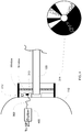
FIG. 2 illustrates an embodiment of an angle sensor in accordance with the principles and teachings of the disclosure; -
FIG.3 illustrates an embodiment of an angle sensor in accordance with the principles and teachings of the disclosure; -
FIG. 4 illustrates an embodiment of an angle sensor in accordance with the principles and teachings of the disclosure; -
FIG. 5 illustrates one implementation of the endoscopic device, showing the ability of the outer lumen, along with a distal lens, prism, and sensor, of the endoscope to rotate to create a wide angle field of vision; -
FIG. 6 illustrates one implementation of the endoscopic device, showing the ability of the outer lumen, along with a distal lens, prism, and sensor of the endoscope to rotate to create a wide angle field of vision; -
FIGS. 7A and 7B illustrate a perspective view and a side view, respectively, of an implementation of a monolithic sensor having a plurality of pixel arrays for producing a three dimensional image in accordance with the teachings and principles of the disclosure; -
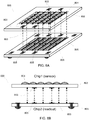
FIGS. 8A and 8B illustrate a perspective view and a side view, respectively, of an implementation of an imaging sensor built on a plurality of substrates, wherein a plurality of pixel columns forming the pixel array are located on the first substrate and a plurality of circuit columns are located on a second substrate and showing an electrical connection and communication between one column of pixels to its associated or corresponding column of circuitry; and -
FIGS. 9A and 9B illustrate a perspective view and a side view, respectively, of an implementation of an imaging sensor having a plurality of pixel arrays for producing a three dimensional image, wherein the plurality of pixel arrays and the image sensor are built on a plurality of substrates. - For reasons of cost and simplicity, an improved endoscope design concept involves placing an image sensor within the endoscope itself and transmitting the image data to the remainder of the camera system electrically. In an implementation of the disclosure, the image sensor may be placed within a distal end of the endoscope. The challenge for such a system is to maintain high image quality using a sensor that is space constrained. This challenge may be overcome by a system that incorporates a monochrome image sensor with minimal peripheral circuitry, connection pads and logic. Color information is provided by pulsing different frames with different wavelengths of light using, e.g., laser or LED light sources. The image sensor is able to capture frames within 1/120 s or less, thereby producing full color video at a rate of 60Hz or higher.
- Another challenge arising from this approach is in providing a final image orientation for a user, which still reflects the hand-piece orientation with respect to the scene. One, purely mechanical approach is to have the sensor be rigidly coupled to the hand-piece and to rotate the endoscope, including the lens stack, at the front end independently. This may be accomplished by incorporating two concentric tubes. The system allows for a distal prism to rotate, which changes the angle of view of the user or operator, while the sensor remains fixed at a constant location. This allows the device to be used in the same manner as expected by a user or operator experienced in using conventional rigid endoscopy systems. The user or operator may rotate an outer lumen, thereby changing the angle of view, while the sensor remains in a fixed position and the image viewable on screen remains at a constant horizon. The prism may rotate while the sensor does not rotate, such that the user does not lose orientation.
- This disclosure extends to an alternative approach in which the sensor is rigidly coupled, along with the lens stack, to a single tube while the digital images are rotated in the image signal processing pipeline or chain (ISP). The disclosure contemplates using a digital representation of the angle of the endoscope tube with respect to the hand-piece that is continuously available to the ISP during operation. Several approaches to this are possible, as described more fully herein.
- The disclosure also extends to a solution for endoscopy applications in which the image sensor is resident at the distal end of the endoscope. With an image sensor located in the distal end of an endoscopic device, there are challenges present, which are not at issue when the imaging sensor is located remotely from the distal end of the endoscopic device. For example, when a user or operator rotates or changes the angle of the endoscopic device, which is common during a surgery, the image sensor will change orientation and the image horizon shown on screen will also change. What is needed are devices and systems that accommodate an image sensor being located in the distal end of the endoscopic device without changing the orientation and maintaining a constant image horizon for the user or operator. As will be seen, the disclosure provides devices and systems that can do this in an efficient and elegant manner.
- In the following description of the disclosure, reference is made to the accompanying drawings, which form a part hereof, and in which is shown by way of illustration specific implementations in which the disclosure may be practiced. It is understood that other implementations may be utilized and structural changes may be made without departing from the scope of the disclosure.
- It must be noted that, as used in this specification and the appended claims, the singular forms "a," "an," and "the" include plural referents unless the context clearly dictates otherwise.
- As used herein, the terms "comprising," "including," "containing," "characterized by," and grammatical equivalents thereof are inclusive or open-ended terms that do not exclude additional, unrecited elements or method steps.
- Further, where appropriate, functions described herein can be performed in one or more of: hardware, software, firmware, digital components, or analog components. For example, one or more application specific integrated circuits (ASICs) can be programmed to carry out one or more of the systems and procedures described herein. Certain terms are used throughout the following description and Claims to refer to particular system components. As one skilled in the art will appreciate, components may be referred to by different names. This document does not intend to distinguish between components that differ in name, but not function.
- Referring now to
FIG. 1 , an endoscopic device of the disclosure is illustrated. The mechanical structure of theendoscope 100 of the disclosure comprises a hand-piece unit 110 and anendoscope tube 120, which freely rotate relative to each other. As illustrated best inFIG. 1 , the endoscope may also comprise anelectrical cable 130 attached to the hand-piece 110. Alight cable 150 may be attached to theendoscope 120. Animage sensor 140 may be located within the hand-piece 110 or theendoscope tube 120, such that the rotation of the hand-piece 110 relative to theendoscope tube 120 creates an image horizon that may change depending upon the user's orientation of the hand-piece 110. In an implementation, theimage sensor 140 may be located in the distal end of theendoscope tube 120, such that the rotation of the hand-piece 110 relative to theendoscope tube 120 creates an image horizon that may change depending upon the user's orientation of the hand-piece 110. To compensate for this changing orientation, the disclosure may utilize the following devices, methods and systems to detect an angle of the hand-piece 110 with respect to theendoscope tube 120. - Referring now to
FIG. 2 , in one implementation, a rotation-detecting Hall-effect sensor 112 may be located in the hand-piece 110. Thesensor 112 may be used to detect the angle of a diametrically-polarized, magnetic annulus ordisk 114 illustrated inFIG. 2 . This type of Hall-effect sensor 112 produces a voltage, which indicates the direction of the magnetic field and may be used to determine the angle of the annulus ordisk 114 and thus, the angle of theendoscope tube 120. - Referring now to
FIG. 3 , in one implementation, apotentiometer 212 may be integrated into the junction between the hand-piece 110 andendoscope tube 120 illustrated inFIG. 1 . Thepotentiometer 212 illustrated inFIG. 3 may comprise a carbon track orfilament 213 that may be rigidly attached to theendoscope tube 120. Thepotentiometer 212 may further comprise awiper 214 that may be rigidly attached to the hand-piece 110. It will be appreciated that the resistance may be measured between one end of thepotentiometer 212 and thewiper 214, which will then indicate the angle for the configuration illustrated inFIG. 3 . A potential divider arrangement may also be used for which the voltage seen at thewiper 214 will provide the angle measurement. - Referring now to
FIG. 4 , in one implementation, a combination of an LED or similarlight source 312 and alight detector 313, such as a photodiode or a phototransistor, may be incorporated into, or may be part of, or may be attached to the hand-piece 110. A continuous reflecting annulus ordisk 314, with variable reflectivity, may be rigidly attached to thescope 120. The reflectivity may vary linearly with the angle, or a set of mirrors of suitably varying reflectivity, may be located at regular angular intervals. The amount of light from thelight source 312, such as an LED source or other light source, reflected back at or to thelight detector 313 indicates the angle. - For each of the implementations discussed above, any pertinent
resultant voltage 300 is fed to an analog-digital converter (ADC) ordigitizer 400. The digital number is then relayed to the ISP or the camera processing chain. The angle-sensing elements (112, 114; 212, 213, 214; and 312, 313, 314) discussed above may be placed into or as part of a fixed hand-piece 110 where thescope 120 rotates with respect to the fixed hand-piece system, which is illustrated best inFIGS. 5 and6 . InFIG. 6 , the hand-piece 110 has been removed for purposes of clarity only. - As illustrated in
FIGS. 5 and6 , the system may comprise a fixed hand-piece component 110 or set of components with a cylindrical opening on the distal end of the hand-piece. Within the cylindrical opening thescope 120 is restrained in the axial direction, but allowed to rotate about the axis. In addition to the components mentioned with respect toFIG. 1 , the system may further comprise aninterface component 160 that may be fixed to the hand-piece 110, arotation sleeve 170, arotation post 175, supporting electronics andcircuitry 142 for theimage sensor 140, asensor wire harness 144, alens stack 180, which includes a distal prism, located distally of thescope tube 120, and alens holder 182. A method is shown inFIG. 6 where the combination of therotation sleeve 170 androtation post 175 act to constrain thescope 120 axially. There may be additional material between theinterface component 160 and therotation sleeve 170 to either add or reduce friction to achieve a torque that is low enough to be ergonomically pleasing, but high enough to prevent accidental rotation. - The
rotation post 175 allows the user to rotate thescope 120 in a way that is similar to rotating a conventional scope (as shown inFIG. 1 ). As therotation post 175 rotates, the entire scope assembly also rotates, including thedistal imaging sensor 140 and attachedlens stack 180. As can be seen, the viewing angle dictated by the distal prism changes and allows the user a broader or different view of the surgical scene. - For each embodiment, the rotating and fixed components of the angle detection system can be mounted to the
rotation sleeve 170 and hand-piece 110, respectively. - It will be appreciated that the digital angle information may be made available to the image processing chain where it is sampled periodically (e.g., each frame) and quantized appropriately to, e.g., 5° or 10°, units. In order to prevent rapid angular oscillation of the final image between adjacent angles, a degree of hysteresis is required. One approach is to only allow an image transformation if the same quantized angle has been observed consistently within the previous n samples, where n would be tuned to the satisfaction of the user.
- The basis of rotation of an image plane through angle θ is described by the following transformation:


- This approach results in multiple candidate cases and void pixels, however. The void pixels can be filled by nearest neighbor substitution, which has a resolution and artifact penalty, or by interpolation (e.g., bilinear or bicubic), requiring an occupancy investigation in their localities.
- A more practical approach is afforded by taking each final integer pixel location and applying the inverse rotation transformation to arrive at real-number coordinates within the original plane:


- Since pixel data within that plane are known to be at all integer coordinates, it is straightforward to derive an interpolated image content estimate. This interpolation can again either be bilinear or bicubic, e.g., Bilinear interpolation requires knowing only the closest four pixels, (two in each dimension). They are identified as (Xa, Ya ), (Xa, Yb ), (Xb, Ya ) and (Xb, Yb ), where:


- Referring now to
FIGS. 7A and 7B , the figures illustrate a perspective view and a side view, respectively, of an implementation of amonolithic sensor 700 having a plurality of pixel arrays for producing a three dimensional image in accordance with the teachings and principles of the disclosure. Such an implementation may be desirable for three dimensional image capture, wherein the twopixel arrays first pixel array 702 and asecond pixel array 704 may be dedicated to receiving a predetermined range of wave lengths of electromagnetic radiation, wherein thefirst pixel array 702 is dedicated to a different range of wave length electromagnetic radiation than thesecond pixel array 704. -
FIGS. 8A and 8B illustrate a perspective view and a side view, respectively, of an implementation of animaging sensor 800 built on a plurality of substrates. As illustrated, a plurality ofpixel columns 804 forming the pixel array are located on thefirst substrate 802 and a plurality ofcircuit columns 808 are located on asecond substrate 806. Also illustrated in the figure are the electrical connection and communication between one column of pixels to its associated or corresponding column of circuitry. In one implementation, an image sensor, which might otherwise be manufactured with its pixel array and supporting circuitry on a single, monolithic substrate/chip, may have the pixel array separated from all or a majority of the supporting circuitry. The disclosure may use at least two substrates/chips, which will be stacked together using three-dimensional stacking technology. The first 802 of the two substrates/chips may be processed using an image CMOS process. The first substrate/chip 802 may be comprised either of a pixel array exclusively or a pixel array surrounded by limited circuitry. The second or subsequent substrate/chip 806 may be processed using any process, and does not have to be from an image CMOS process. The second substrate/chip 806 may be, but is not limited to, a highly dense digital process in order to integrate a variety and number of functions in a very limited space or area on the substrate/chip, or a mixed-mode or analog process in order to integrate for example precise analog functions, or a RF process in order to implement wireless capability, or MEMS (Micro-Electro-Mechanical Systems) in order to integrate MEMS devices. The image CMOS substrate/chip 802 may be stacked with the second or subsequent substrate/chip 806 using any three-dimensional technique. The second substrate/chip 806 may support most, or a majority, of the circuitry that would have otherwise been implemented in the first image CMOS chip 802 (if implemented on a monolithic substrate/chip) as peripheral circuits and therefore have increased the overall system area while keeping the pixel array size constant and optimized to the fullest extent possible. The electrical connection between the two substrates/chips may be done throughinterconnects -
FIGS. 9A and 9B illustrate a perspective view and a side view, respectively, of an implementation of animaging sensor 900 having a plurality of pixel arrays for producing a three dimensional image. The three dimensional image sensor may be built on a plurality of substrates and may comprise the plurality of pixel arrays and other associated circuitry, wherein a plurality ofpixel columns 904a forming the first pixel array and a plurality ofpixel columns 904b forming a second pixel array are located onrespective substrates circuit columns separate substrate 906. Also illustrated are the electrical connections and communications between columns of pixels to associated or corresponding column of circuitry. - It will be appreciated that the teachings and principles of the disclosure may be used in a reusable device platform, a limited use device platform, a re-posable use device platform, or a single-use/disposable device platform without departing from the scope of the disclosure. It will be appreciated that in a re-usable device platform an end-user is responsible for cleaning and sterilization of the device. In a limited use device platform the device can be used for some specified amount of times before becoming inoperable. Typical new device is delivered sterile with additional uses requiring the end-user to clean and sterilize before additional uses. In a re-posable use device platform a third-party may reprocess the device (e.g., cleans, packages and sterilizes) a single-use device for additional uses at a lower cost than a new unit. In a single-use/disposable device platform a device is provided sterile to the operating room and used only once before being disposed of.
- Additionally, the teachings and principles of the disclosure may include any and all wavelengths of electromagnetic energy, including the visible and non-visible spectrums, such as infrared (IR), ultraviolet (UV), and X-ray.
- The foregoing description has been presented for the purposes of illustration and description. It is not intended to be exhaustive or to limit the disclosure to the precise form disclosed. Many modifications and variations are possible in light of the above teaching. Further, it should be noted that any or all of the aforementioned alternate implementations may be used in any combination desired to form additional hybrid implementations of the disclosure.
- Further, although specific implementations of the disclosure have been described and illustrated, the disclosure is not to be limited to the specific forms or arrangements of parts so described and illustrated. The scope of the disclosure is to be defined by the claims appended hereto, any future claims submitted here and in different applications, and their equivalents.
-
- 1. An endoscopic device comprising:
- a hand-piece;
- a proximal portion and a distal portion comprising a tip;
- a lumen;
- an image sensor disposed within the lumen for providing visualization of an area, wherein the image sensor is at the distal portion near the tip of the endoscope;
- an angle sensor for detecting an angle of rotation of the hand-piece relative to the lumen;
- wherein the lumen is rotatable about an axis of the endoscope and with respect to the hand-piece.
- 2. The endoscopic device of aspect 1, wherein the angle sensor is a rotation-detecting Hall-effect sensor.
- 3. The endoscopic device of
aspect 2, wherein the rotation-detecting Hall-effect sensor is located in the hand-piece. - 4: The endoscopic device of
aspect 2, wherein the device further comprises a diametrically-polarized magnetic annulus and wherein the rotation-detecting Hall-effect sensor produces a voltage that is used to detect an angle of the diametrically-polarized, magnetic annulus. - 5. The endoscopic device of aspect 1, wherein the angle sensor produces a voltage that is used to detect an angle of rotation of the hand-piece relative to the lumen.
- 6. The endoscopic device of aspect 1, wherein the angle sensor is a potentiometer.
- 7. The endoscopic device of aspect 6, wherein the potentiometer comprises a carbon filament, wherein the carbon filament of the potentiometer is disposed on said lumen.
- 8. The endoscopic device of aspect 1, where the angle sensor comprises a light source and a photo diode that rotate relative to a gradient disc.
- 9. The endoscopic device of aspect 8, wherein said photo diode detects the electromagnetic energy from said light source that is reflected by said gradient disc.
- 10. The endoscopic device of aspect 1, wherein said image sensor incorporates a two-dimensional array of pixels capable of detecting electromagnetic radiation.
- 11. The endoscopic device of aspect 1, wherein the device comprises an image signal processing pipeline, wherein a process resides for the purpose of performing image rotation transformations upon images captured by the image sensor.
- 12. The endoscopic device of aspect 11, wherein said image rotation transformation comprises taking each initial pixel's integer x,y coordinates and transforming them to final, real number pixel coordinates by applying a rotation kernel.
- 13. The endoscopic device of aspect 12, wherein said image rotation transformation further comprises truncating the final, real number pixel coordinates to integer values, then assigning values to blank pixels in the final image using the values of nearby, filled pixels.
- 14. The endoscopic device of aspect 13, wherein said assignment is performed using bilinear interpolation.
- 15. The endoscopic device of aspect 13, wherein said assignment is performed using bicubic interpolation.
- 16. The endoscopic device of aspect 13, wherein said assignment is performed using nearest neighbor substitution.
- 17. The endoscopic device of aspect 11, wherein said image rotation transformation comprises taking each final pixel's integer x,y coordinates and transforming them to initial real number x,y coordinates by applying an inverse rotation kernel.
- 18. The endoscopic device of aspect 17, wherein said image rotation transformation further comprises estimating a pixel value at the initial real number x,y coordinates, using data from the closest integer coordinate locations.
- 19. The endoscopic device of aspect 18, wherein said estimation is performed using nearest neighbor substitution.
- 20. The endoscopic device of aspect 18, wherein said estimation is performed using bilinear interpolation.
- 21. The endoscopic device of aspect 18, wherein said estimation is performed using bicubic interpolation.
- 22. An endoscopic system comprising:
- an endoscope unit comprising:
- a hand-piece;
- a proximal portion and a distal portion comprising a tip;
- a lumen;
- an image sensor disposed within the lumen for providing visualization of an area, wherein the image sensor is at the distal portion near the tip of the endoscope;
- wherein said image sensor incorporates a two dimensional array of pixels capable of detecting electromagnetic radiation;
- an angle sensor for detecting an angle of rotation of the hand-piece relative to the lumen, wherein the lumen is rotatable about an axis of the endoscope and with respect to the hand-piece; and
- an image signal processing pipeline, wherein a process resides for the purpose of performing rotation transformations upon images captured by the image sensor.
- an endoscope unit comprising:
- 23. A method of rotating an image in an endoscopic application comprising:
- providing an endoscope unit comprising:
- a hand-piece;
- a proximal portion and a distal portion comprising a tip;
- a lumen;
- an image sensor disposed within the lumen for providing visualization of an area, wherein the image sensor is at the distal portion near the tip of the endoscope;
- wherein said image sensor incorporates a two dimensional array of pixels capable of detecting electromagnetic radiation;
- detecting an angle of rotation of the hand-piece relative to the lumen using an angle sensor, wherein the lumen is rotatable about an axis of the endoscope and with respect to the hand-piece; and
- performing image rotation transformations upon images captured by the image sensor using an image signal processing pipeline, wherein a process resides in said image signal processing pipeline.
- providing an endoscope unit comprising:
- 24. The method of aspect 23, wherein the step of performing image rotation transformation comprises taking each initial pixel's integer x,y coordinates and transforming them to final, real number pixel coordinates by applying a rotation kernel.
- 25. The method of aspect 24, wherein said image rotation transformation further comprises truncating the final, real number pixel coordinates to integer values, then assigning values to blank pixels in the final image using the values of nearby, filled pixels.
- 26. The method of aspect 25, wherein said assignment is performed using bilinear interpolation.
- 27. The method of aspect 25, wherein said assignment is performed using bicubic interpolation.
- 28. The method of aspect25, wherein said assignment is performed using nearest neighbor substitution.
- 29. The method of aspect 23, wherein the step of performing image rotation transformation comprises taking each final pixel's integer x,y coordinates and transforming them to initial real number x,y coordinates by applying an inverse rotation kernel.
- 30. The method of aspect 29, wherein said image rotation transformation further comprises estimating a pixel value at the initial real number x,y coordinates, using the data from the closest integer coordinate locations.
- 31. The method of aspect 29, wherein said estimation is performed using nearest neighbor substitution.
- 32. The method of aspect 29, wherein said estimation is performed using bilinear interpolation.
- 33. The method of aspect29, wherein said estimation is performed using bicubic interpolation.
Claims (14)
- An endoscopic system comprising:a light source that pulses different wavelengths of light in different exposure frames; andan endoscope, wherein the endoscope comprises:a hand-piece (110);a proximal portion and a distal portion comprising a tip;an endoscope tube (120) having a lumen, the endoscope tube (120) rotatably attached to the hand-piece (110);a monochrome image sensor (140) that captures the light in each of the different exposure frames, wherein the monochrome image sensor is disposed within the lumen of the endoscope tube (120) for providing visualization of an area, wherein the monochrome image sensor (140) is positioned at the distal portion near the tip of the endoscope tube (120), wherein the image sensor is configured to capture image frames within 1/120s or less thereby providing full color video at a rate of 60hz or higher;an angle sensor for detecting an angle of rotation of the endoscope tube (120) with respect to the hand-piece (110);wherein the endoscope tube (120) is rotatable about an axis of the endoscope tube (120) and with respect to the hand-piece (110), such that the rotation of the hand-piece (110) relative to the endoscope tube (120) creates an image horizon that changes depending upon the user's orientation of the hand-piece (110); andan image signal processing pipeline for performing rotation transformations upon images that are captured by the monochrome image sensor (140) based on the angle of rotation detected by the angle sensor, wherein a digital representation of the angle of the endoscope tube (120) with respect to the hand-piece (110) is continuously available during operation to the image signal processing pipeline, and wherein the image signal processing pipeline is configured to inversely rotate the images with respect to the angle of rotation detected by the angle sensor to maintain a constant image horizon for a user on a display.
- The endoscopic system of claim 1, wherein optionally the angle sensor:(a) is a rotation-detecting Hall-effect sensor, wherein optionally and preferably:the rotation-detecting Hall-effect sensor is located in the hand-piece; orthe device further comprises a diametrically-polarized magnetic annulus and wherein the rotation-detecting Hall-effect sensor produces a voltage that is used to detect an angle of the diametrically-polarized, magnetic annulus; or(b) produces a voltage that is used to detect an angle of rotation of the hand-piece relative to the endoscope tube; or(c) is a potentiometer, wherein optionally and preferably the potentiometer comprises a carbon filament, wherein the carbon filament of the potentiometer is disposed on said endoscope tube; or(d) comprises a light source and a photo diode that rotate relative to a gradient disc, wherein optionally and preferably said photo diode detects the electromagnetic energy from said light source that is reflected by said gradient disc.
- The endoscopic system of claim 1, wherein said monochrome image sensor incorporates a two-dimensional array of pixels capable of detecting electromagnetic radiation.
- The endoscopic system of claim 1, wherein said image rotation transformation comprises taking each initial pixel's integer x,y coordinates and transforming them to final, real number pixel coordinates by applying a rotation kernel;
wherein optionally said image rotation transformation further comprises truncating the final, real number pixel coordinates to integer values, then assigning values to blank pixels in the final image using the values of nearby, filled pixels;
wherein optionally and preferably:said assignment is performed using bilinear interpolation; orsaid assignment is performed using bicubic interpolation; orsaid assignment is performed using nearest neighbor substitution. - The endoscopic system of claim 1, wherein said image rotation transformation comprises taking each final pixel's integer x,y coordinates and transforming them to initial real number x,y coordinates by applying an inverse rotation kernel;
wherein optionally said image rotation transformation further comprises estimating a pixel value at the initial real number x,y coordinates, using data from the closest integer coordinate locations;
wherein optionally and preferably:said estimation is performed using nearest neighbor substitution; orsaid estimation is performed using bilinear interpolation; orsaid estimation is performed using bicubic interpolation. - The endoscopic system of claim 1, wherein the digital representation of the angle is made available to and sampled periodically by the image processing pipeline, wherein the digital representation of the angle is quantized in units;
wherein a degree of hysteresis is performed to prevent rapid angular oscillation of the final image between adjacent angles, wherein an image transformation is performed only if the same quantized angle has been observed consistently within the previous "n" samples, where "n" is tunable by a user. - A method of rotating an image in an endoscopic application comprising:providing an endoscopic system comprising:a light source that pulses different wavelengths of light in different exposure frames; andan endoscope, wherein the endoscope comprises:a hand-piece (110);a proximal portion and a distal portion comprising a tip;an endoscope tube (120) having a lumen, the endoscope tube (120) rotatably attached to the hand-piece (110);a monochrome image sensor (140) that captures the light in each of the different exposure frames, wherein the monochrome image sensor is disposed within the lumen of the endoscope tube (120) for providing visualization of an area, wherein the monochrome image sensor (140) is positioned at the distal portion near the tip of the endoscope tube (120), wherein the image sensor is configured to capture image frames within 1/120s or less thereby providing full color video at a rate of 60hz or higher;wherein said monochrome image sensor incorporates a two-dimensional array of pixels capable of detecting electromagnetic radiation;detecting an angle of rotation of the hand-piece relative to the endoscope tube (120) using an angle sensor, wherein the endoscope tube (120) is rotatable about an axis of the endoscope tube (120) and with respect to the hand-piece (110)), such that the rotation of the hand-piece (110) relative to the endoscope tube (120) creates an image horizon that changes depending upon the user's orientation of the hand-piece (110); andperforming image rotation transformations upon images captured by the monochrome image sensor (140) based on the angle of rotation detected by the angle sensor using an image signal processing pipeline, wherein a digital representation of the angle of the endoscope tube (120) with respect to the hand-piece (110) is continuously available during operation to the image signal processing pipeline, and wherein the image signal processing pipeline is configured to inversely rotate the images with respect to the angle of rotation detected by the angle sensor to maintain a constant image horizon for a user on a display.
- The method of claim 7, wherein the step of performing image rotation transformation comprises taking each initial pixel's integer x,y coordinates and transforming them to final, real number pixel coordinates by applying a rotation kernel.
- The method of claim 8, wherein said image rotation transformation further comprises truncating the final, real number pixel coordinates to integer values, then assigning values to blank pixels in the final image using the values of nearby, filled pixels.
- The method of claim 9, wherein optionally:said assignment is performed using bilinear interpolation; orsaid assignment is performed using bicubic interpolation; orsaid assignment is performed using nearest neighbor substitution.
- The method of claim 7, wherein the step of performing image rotation transformation comprises taking each final pixel's integer x,y coordinates and transforming them to initial real number x,y coordinates by applying an inverse rotation kernel.
- The method of claim 11, wherein said image rotation transformation further comprises estimating a pixel value at the initial real number x,y coordinates, using the data from the closest integer coordinate locations.
- The method of claim 12, wherein optionally:said estimation is performed using nearest neighbor substitution; orsaid estimation is performed using bilinear interpolation; orsaid estimation is performed using bicubic interpolation.
- The method of claim 7, wherein the digital representation of the angle is made available to and sampled periodically by the image processing pipeline, wherein the digital representation of the angle is quantized in units;
wherein a degree of hysteresis is performed to prevent rapid angular oscillation of the final image between adjacent angles, wherein an image transformation is performed only if the same quantized angle has been observed consistently within the previous "n" samples, where "n" is tunable by a user.
Applications Claiming Priority (3)
| Application Number | Priority Date | Filing Date | Title |
|---|---|---|---|
| US201361792119P | 2013-03-15 | 2013-03-15 | |
| PCT/US2014/029655 WO2014145019A1 (en) | 2013-03-15 | 2014-03-14 | Image rotation using software for endoscopic applications |
| EP14763366.3A EP2967302A4 (en) | 2013-03-15 | 2014-03-14 | Image rotation using software for endoscopic applications |
Related Parent Applications (1)
| Application Number | Title | Priority Date | Filing Date |
|---|---|---|---|
| EP14763366.3A Division EP2967302A4 (en) | 2013-03-15 | 2014-03-14 | Image rotation using software for endoscopic applications |
Publications (2)
| Publication Number | Publication Date |
|---|---|
| EP3539457A1 true EP3539457A1 (en) | 2019-09-18 |
| EP3539457B1 EP3539457B1 (en) | 2021-12-08 |
Family
ID=51537861
Family Applications (2)
| Application Number | Title | Priority Date | Filing Date |
|---|---|---|---|
| EP19162015.2A Not-in-force EP3539457B1 (en) | 2013-03-15 | 2014-03-14 | Image rotation using software for endoscopic applications |
| EP14763366.3A Ceased EP2967302A4 (en) | 2013-03-15 | 2014-03-14 | Image rotation using software for endoscopic applications |
Family Applications After (1)
| Application Number | Title | Priority Date | Filing Date |
|---|---|---|---|
| EP14763366.3A Ceased EP2967302A4 (en) | 2013-03-15 | 2014-03-14 | Image rotation using software for endoscopic applications |
Country Status (6)
| Country | Link |
|---|---|
| US (2) | US10362240B2 (en) |
| EP (2) | EP3539457B1 (en) |
| JP (1) | JP6339172B2 (en) |
| AU (1) | AU2014233497B2 (en) |
| CA (1) | CA2907171A1 (en) |
| WO (1) | WO2014145019A1 (en) |
Cited By (1)
| Publication number | Priority date | Publication date | Assignee | Title |
|---|---|---|---|---|
| EP4169469A1 (en) | 2021-10-25 | 2023-04-26 | Erbe Vision GmbH | Laparoskopic camera arrangement and method for camera alignment error correction |
Families Citing this family (33)
| Publication number | Priority date | Publication date | Assignee | Title |
|---|---|---|---|---|
| US10616491B2 (en) | 2013-02-01 | 2020-04-07 | Deka Products Limited Partnership | Endoscope with pannable camera and related method |
| EP3539457B1 (en) | 2013-03-15 | 2021-12-08 | DePuy Synthes Products, Inc. | Image rotation using software for endoscopic applications |
| US10390689B2 (en) * | 2014-03-17 | 2019-08-27 | Intuitive Surgical Operations, Inc. | Angled endoscope tip image capture unit |
| WO2015151543A1 (en) * | 2014-03-31 | 2015-10-08 | ソニー・オリンパスメディカルソリューションズ株式会社 | Operating device for medical apparatus |
| CN105769249B (en) * | 2014-12-24 | 2019-06-11 | 珂纳医疗科技(苏州)有限公司 | photoacoustic imaging endoscope |
| KR20250172897A (en) * | 2015-09-01 | 2025-12-09 | 데카 프로덕츠 리미티드 파트너쉽 | Endoscope with pannable camera and related method |
| US12150636B2 (en) | 2015-09-04 | 2024-11-26 | Medos International Sárl | Surgical instrument connectors and related methods |
| CN113143355A (en) | 2015-09-04 | 2021-07-23 | 美多斯国际有限公司 | Multi-shield spinal access system |
| US11439380B2 (en) | 2015-09-04 | 2022-09-13 | Medos International Sarl | Surgical instrument connectors and related methods |
| US11672562B2 (en) | 2015-09-04 | 2023-06-13 | Medos International Sarl | Multi-shield spinal access system |
| US10987129B2 (en) | 2015-09-04 | 2021-04-27 | Medos International Sarl | Multi-shield spinal access system |
| US11744447B2 (en) | 2015-09-04 | 2023-09-05 | Medos International | Surgical visualization systems and related methods |
| US10337987B2 (en) | 2017-06-16 | 2019-07-02 | Canon U.S.A. , Inc. | Radial-line scanning spectrometer with two-dimensional sensor |
| WO2019136172A1 (en) * | 2018-01-03 | 2019-07-11 | Xenocor, Inc. | Angled borescopes with digital image orientation |
| US11712149B2 (en) * | 2018-02-14 | 2023-08-01 | Suzhou Acuvu Medical Technology Co, Ltd. | Endoscopy devices and methods of use |
| JP7595027B2 (en) | 2019-04-30 | 2024-12-05 | テルモ カーディオバスキュラー システムズ コーポレイション | Endoscopic vessel harvesting device with gyro sensor for rotating the camera view - Patents.com |
| US11141052B2 (en) * | 2019-06-20 | 2021-10-12 | Cilag Gmbh International | Image rotation in an endoscopic fluorescence imaging system |
| US11671691B2 (en) | 2019-06-20 | 2023-06-06 | Cilag Gmbh International | Image rotation in an endoscopic laser mapping imaging system |
| US11134832B2 (en) * | 2019-06-20 | 2021-10-05 | Cilag Gmbh International | Image rotation in an endoscopic hyperspectral, fluorescence, and laser mapping imaging system |
| US11172811B2 (en) * | 2019-06-20 | 2021-11-16 | Cilag Gmbh International | Image rotation in an endoscopic fluorescence imaging system |
| JP7426248B2 (en) * | 2020-01-29 | 2024-02-01 | ソニー・オリンパスメディカルソリューションズ株式会社 | Medical control device and medical observation system |
| US11497382B1 (en) | 2020-04-27 | 2022-11-15 | Canon U.S.A., Inc. | Apparatus and method for endoscopic image orientation control |
| ES3033069T3 (en) * | 2020-10-16 | 2025-07-30 | Resnent Llc | Endoscope attachment mechanisms and methods of use |
| US12070196B2 (en) | 2020-11-23 | 2024-08-27 | Medos International Sarl | Arthroscopic medical implements and assemblies |
| US20220160220A1 (en) * | 2020-11-23 | 2022-05-26 | Medos International Sárl | Arthroscopic medical implements and assemblies |
| EP4251084A4 (en) * | 2020-11-24 | 2024-10-02 | Auris Health, Inc. | Visualization adjustments for instrument roll |
| WO2022176943A1 (en) * | 2021-02-22 | 2022-08-25 | パナソニックIpマネジメント株式会社 | Intraoral camera system and image display method |
| US20240090922A1 (en) * | 2021-05-05 | 2024-03-21 | Intravu Inc. | Miniature Angle-View Endoscope with Image Orientation Correction |
| US12527460B2 (en) | 2021-10-27 | 2026-01-20 | Meditrina, Inc. | Endoscopic imaging and control system |
| US20230128846A1 (en) * | 2021-10-27 | 2023-04-27 | Meditrina, Inc. | Endoscopic imaging and control system |
| US12238265B2 (en) | 2022-12-12 | 2025-02-25 | Cilag Gmbh International | Optical filter for improved multispectral imaging performance in stereo camera |
| US12316965B2 (en) | 2023-02-27 | 2025-05-27 | Cilag Gmbh International | Adaptive overlay stabilization of false color overlay heatmaps |
| US12470831B2 (en) | 2023-08-23 | 2025-11-11 | Cilag Gmbh International | Variable image sensor settings on a per-frame basis |
Citations (3)
| Publication number | Priority date | Publication date | Assignee | Title |
|---|---|---|---|---|
| WO2005031433A1 (en) * | 2003-09-26 | 2005-04-07 | Tidal Photonics, Inc. | Apparatus and methods relating to color imaging endoscope systems |
| US6916286B2 (en) * | 2001-08-09 | 2005-07-12 | Smith & Nephew, Inc. | Endoscope with imaging probe |
| US20080159653A1 (en) * | 2006-12-28 | 2008-07-03 | Microvision | Rotation compensation and image stabilization system |
Family Cites Families (59)
| Publication number | Priority date | Publication date | Assignee | Title |
|---|---|---|---|---|
| JPS57164031A (en) | 1981-04-01 | 1982-10-08 | Olympus Optical Co | Light source apparatus for endoscope |
| JPS5970381A (en) * | 1982-10-15 | 1984-04-20 | Olympus Optical Co Ltd | Endoscope video system |
| JP3164609B2 (en) | 1990-10-31 | 2001-05-08 | オリンパス光学工業株式会社 | Endoscope device |
| US5241170A (en) | 1992-02-19 | 1993-08-31 | Itt Corporation | Fiber optic imaging device and methods |
| JPH06209904A (en) * | 1993-01-14 | 1994-08-02 | Olympus Optical Co Ltd | Endoscope |
| AU687045B2 (en) * | 1993-03-31 | 1998-02-19 | Luma Corporation | Managing information in an endoscopy system |
| US5624398A (en) * | 1996-02-08 | 1997-04-29 | Symbiosis Corporation | Endoscopic robotic surgical tools and methods |
| JP3782532B2 (en) * | 1997-01-07 | 2006-06-07 | オリンパス株式会社 | Stereoscopic electronic endoscope |
| US7453490B2 (en) * | 1997-01-31 | 2008-11-18 | Gyrus Acmi, Inc. | Correction of image signals characteristic of non-uniform images in an endoscopic imaging system |
| US6073043A (en) * | 1997-12-22 | 2000-06-06 | Cormedica Corporation | Measuring position and orientation using magnetic fields |
| AU3893299A (en) * | 1998-05-13 | 1999-11-29 | Inbae Yoon | Penetrating endoscope and endoscopic surgical instrument with cmos image sensor and display |
| US6485414B1 (en) | 1998-07-13 | 2002-11-26 | Ceramoptec Industries, Inc. | Color video diagnostic system for mini-endoscopes |
| US6419626B1 (en) * | 1998-08-12 | 2002-07-16 | Inbae Yoon | Surgical instrument endoscope with CMOS image sensor and physical parameter sensor |
| DE19839188C2 (en) | 1998-08-28 | 2003-08-21 | Storz Endoskop Gmbh Schaffhaus | endoscope |
| US6902527B1 (en) | 1999-05-18 | 2005-06-07 | Olympus Corporation | Endoscope system with charge multiplying imaging device and automatic gain control |
| DE29910795U1 (en) | 1999-06-21 | 1999-09-02 | Richard Wolf Gmbh, 75438 Knittlingen | Electronic endoscope |
| US6373568B1 (en) | 1999-08-06 | 2002-04-16 | Cambridge Research & Instrumentation, Inc. | Spectral imaging system |
| US6471637B1 (en) | 1999-09-24 | 2002-10-29 | Karl Storz Imaging, Inc. | Image orientation for endoscopic video displays |
| US7037258B2 (en) | 1999-09-24 | 2006-05-02 | Karl Storz Imaging, Inc. | Image orientation for endoscopic video displays |
| US6272269B1 (en) | 1999-11-16 | 2001-08-07 | Dn Labs Inc. | Optical fiber/waveguide illumination system |
| US20010030744A1 (en) | 1999-12-27 | 2001-10-18 | Og Technologies, Inc. | Method of simultaneously applying multiple illumination schemes for simultaneous image acquisition in an imaging system |
| US6961461B2 (en) | 2000-05-17 | 2005-11-01 | Tidal Photonics, Inc. | Apparatus and method for measurement, encoding and displaying of object color for digital imaging |
| JP2001174897A (en) * | 2000-10-13 | 2001-06-29 | Yoshida Dental Mfg Co Ltd | Ccd camera for dentistry |
| JP4390096B2 (en) | 2001-07-06 | 2009-12-24 | 富士フイルム株式会社 | Endoscope device |
| US6921920B2 (en) | 2001-08-31 | 2005-07-26 | Smith & Nephew, Inc. | Solid-state light source |
| US6692431B2 (en) | 2001-09-07 | 2004-02-17 | Smith & Nephew, Inc. | Endoscopic system with a solid-state light source |
| US6899675B2 (en) | 2002-01-15 | 2005-05-31 | Xillix Technologies Corp. | Fluorescence endoscopy video systems with no moving parts in the camera |
| JP3831273B2 (en) * | 2002-02-05 | 2006-10-11 | オリンパス株式会社 | Electronic endoscope |
| EP1499235B1 (en) | 2002-04-17 | 2016-08-17 | Covidien LP | Endoscope structures and techniques for navigating to a target in branched structure |
| US7794394B2 (en) | 2002-05-22 | 2010-09-14 | Beth Israel Deaconess Medical Center | Device for wavelength-selective imaging |
| US7578786B2 (en) | 2003-04-01 | 2009-08-25 | Boston Scientific Scimed, Inc. | Video endoscope |
| JP2007500546A (en) | 2003-07-28 | 2007-01-18 | ディー オウルド、マイケル | Coaxially illuminated laser endoscope probe and active numerical aperture control |
| CA2581668A1 (en) | 2003-09-26 | 2005-04-07 | Tidal Photonics, Inc | Apparatus and methods relating to expanded dynamic range imaging endoscope systems |
| US7326205B2 (en) * | 2004-01-16 | 2008-02-05 | St. Jude Medical, Atrial Fibrillation Division, Inc. | Surgical device with brush electrode and methods for electrosurgical treatment |
| US7976462B2 (en) * | 2004-04-06 | 2011-07-12 | Integrated Endoscopy, Inc. | Endoscope designs and methods of manufacture |
| US8517921B2 (en) * | 2004-04-16 | 2013-08-27 | Gyrus Acmi, Inc. | Endoscopic instrument having reduced diameter flexible shaft |
| JP2005328970A (en) * | 2004-05-19 | 2005-12-02 | Olympus Corp | Endoscope apparatus |
| US8556806B2 (en) | 2004-09-24 | 2013-10-15 | Vivid Medical, Inc. | Wavelength multiplexing endoscope |
| US8480566B2 (en) | 2004-09-24 | 2013-07-09 | Vivid Medical, Inc. | Solid state illumination for endoscopy |
| EP1983883B1 (en) | 2006-02-07 | 2015-11-18 | Boston Scientific Limited | Medical device light source |
| US8248413B2 (en) * | 2006-09-18 | 2012-08-21 | Stryker Corporation | Visual navigation system for endoscopic surgery |
| JP5199634B2 (en) * | 2007-10-02 | 2013-05-15 | オリンパス株式会社 | Measuring endoscope system |
| JP5121506B2 (en) * | 2008-02-29 | 2013-01-16 | キヤノン株式会社 | Image processing apparatus, image processing method, program, and storage medium |
| DE102008033506A1 (en) * | 2008-07-07 | 2010-01-14 | Karl Storz Gmbh & Co. Kg | Video endoscope with switchable semiconductor light sources |
| US9518815B2 (en) * | 2008-08-06 | 2016-12-13 | Haas Automation, Inc. | Rotary position encoder for rotatable shafts |
| DE102008057734B4 (en) * | 2008-11-17 | 2016-07-28 | Digital Endoscopy Gmbh | Videoscope |
| US8357175B2 (en) | 2008-12-16 | 2013-01-22 | Nico Corporation | Positioning system for tissue removal device |
| EP2429376B1 (en) * | 2009-05-08 | 2016-10-19 | Boston Scientific Scimed, Inc. | Endoscope with distal tip having encased optical components and display orientation capabilities |
| JP5396178B2 (en) * | 2009-07-13 | 2014-01-22 | 富士フイルム株式会社 | Endoscope apparatus and endoscope system |
| US8444272B2 (en) | 2010-01-25 | 2013-05-21 | Corning Incorporated | Multi-projector system using multiplexed illumination |
| JP5393554B2 (en) | 2010-03-23 | 2014-01-22 | 富士フイルム株式会社 | Electronic endoscope system |
| JP5438571B2 (en) | 2010-03-24 | 2014-03-12 | 富士フイルム株式会社 | Electronic endoscope system |
| US20120004508A1 (en) | 2010-07-02 | 2012-01-05 | Mcdowall Ian | Surgical illuminator with dual spectrum fluorescence |
| WO2012021212A1 (en) | 2010-08-10 | 2012-02-16 | Boston Scientific Scimed, Inc. | Endoscopic system for enhanced visualization |
| WO2012116339A1 (en) | 2011-02-24 | 2012-08-30 | Olive Medical Corporation | Imaging sensor providing improved visualization for surgical scopes |
| KR20120114895A (en) | 2011-04-08 | 2012-10-17 | 삼성전자주식회사 | Endoscope apparatus and image acquisition method of the endoscope |
| CA2835870A1 (en) * | 2011-05-12 | 2012-11-15 | Olive Medical Corporation | Pixel array area optimization using stacking scheme for hybrid image sensor with minimal vertical interconnects |
| US20130155305A1 (en) | 2011-12-19 | 2013-06-20 | Sony Corporation | Orientation of illustration in electronic display device according to image of actual object being illustrated |
| EP3539457B1 (en) | 2013-03-15 | 2021-12-08 | DePuy Synthes Products, Inc. | Image rotation using software for endoscopic applications |
-
2014
- 2014-03-14 EP EP19162015.2A patent/EP3539457B1/en not_active Not-in-force
- 2014-03-14 JP JP2016503183A patent/JP6339172B2/en not_active Expired - Fee Related
- 2014-03-14 EP EP14763366.3A patent/EP2967302A4/en not_active Ceased
- 2014-03-14 CA CA2907171A patent/CA2907171A1/en not_active Abandoned
- 2014-03-14 US US14/214,412 patent/US10362240B2/en active Active
- 2014-03-14 WO PCT/US2014/029655 patent/WO2014145019A1/en not_active Ceased
- 2014-03-14 AU AU2014233497A patent/AU2014233497B2/en not_active Ceased
-
2019
- 2019-07-11 US US16/509,297 patent/US12003880B2/en active Active
Patent Citations (3)
| Publication number | Priority date | Publication date | Assignee | Title |
|---|---|---|---|---|
| US6916286B2 (en) * | 2001-08-09 | 2005-07-12 | Smith & Nephew, Inc. | Endoscope with imaging probe |
| WO2005031433A1 (en) * | 2003-09-26 | 2005-04-07 | Tidal Photonics, Inc. | Apparatus and methods relating to color imaging endoscope systems |
| US20080159653A1 (en) * | 2006-12-28 | 2008-07-03 | Microvision | Rotation compensation and image stabilization system |
Non-Patent Citations (6)
| Title |
|---|
| ANONYMOUS: "Olympus Microscopy Resource Center | Geometrical Transformation - Java Tutorial", 31 December 2012 (2012-12-31), XP055294458, Retrieved from the Internet <URL:http://www.olympusmicro.com/primer/java/digitalimaging/processing/geometricaltransformation/index.html> [retrieved on 20160809] * |
| ANONYMOUS: "Potentiometergeber - Wikipedia", 8 October 2012 (2012-10-08), XP055294467, Retrieved from the Internet <URL:https://de.wikipedia.org/w/index.php?title=Potentiometergeber&oldid=109084688> [retrieved on 20160809] * |
| ANONYMOUS: "Resolver (electrical) - Wikipedia, the free encyclopedia", 2 March 2013 (2013-03-02), XP055294466, Retrieved from the Internet <URL:https://en.wikipedia.org/w/index.php?title=Resolver_(electrical)&oldid=541673781> [retrieved on 20160809] * |
| ANONYMOUS: "Rotary encoder - Wikipedia, the free encyclopedia", 5 March 2013 (2013-03-05), XP055294463, Retrieved from the Internet <URL:https://en.wikipedia.org/w/index.php?title=Rotary_encoder&oldid=542165237> [retrieved on 20160809] * |
| DAVID EBERLY: "Integer-Based Rotations of Images Contents", 2 March 2008 (2008-03-02), pages 1 - 5, XP055294442, Retrieved from the Internet <URL:http://www.geometrictools.com/Documentation/IntegerBasedRotation.pdf> [retrieved on 20160809] * |
| HÖLLER KURT ET AL: "Endoscopic Orientation Correction", 20 September 2009, INTERNATIONAL CONFERENCE ON COMPUTER ANALYSIS OF IMAGES AND PATTERNS. CAIP 2017: COMPUTER ANALYSIS OF IMAGES AND PATTERNS; [LECTURE NOTES IN COMPUTER SCIENCE; LECT.NOTES COMPUTER], SPRINGER, BERLIN, HEIDELBERG, PAGE(S) 459 - 466, ISBN: 978-3-642-17318-9, XP047462706 * |
Cited By (2)
| Publication number | Priority date | Publication date | Assignee | Title |
|---|---|---|---|---|
| EP4169469A1 (en) | 2021-10-25 | 2023-04-26 | Erbe Vision GmbH | Laparoskopic camera arrangement and method for camera alignment error correction |
| US12599288B2 (en) | 2021-10-25 | 2026-04-14 | Erbe Vision Gmbh | Endoscopic camera arrangement and method for camera alignment error correction |
Also Published As
| Publication number | Publication date |
|---|---|
| US10362240B2 (en) | 2019-07-23 |
| US20190356867A1 (en) | 2019-11-21 |
| US12003880B2 (en) | 2024-06-04 |
| EP3539457B1 (en) | 2021-12-08 |
| AU2014233497A1 (en) | 2015-11-05 |
| JP6339172B2 (en) | 2018-06-06 |
| JP2016514498A (en) | 2016-05-23 |
| WO2014145019A1 (en) | 2014-09-18 |
| CA2907171A1 (en) | 2014-09-18 |
| EP2967302A4 (en) | 2016-09-14 |
| US20140285644A1 (en) | 2014-09-25 |
| EP2967302A1 (en) | 2016-01-20 |
| AU2014233497B2 (en) | 2018-11-08 |
Similar Documents
| Publication | Publication Date | Title |
|---|---|---|
| US12003880B2 (en) | Image rotation using software for endoscopic applications | |
| US7783133B2 (en) | Rotation compensation and image stabilization system | |
| JP6419774B2 (en) | Minimizing image sensor I/O and conductor count in endoscopic applications | |
| JP7230808B2 (en) | Imaging element and imaging device | |
| US20110251456A1 (en) | Method and Apparatus For Viewing A Body Cavity | |
| EP2244626B1 (en) | Radial scanner imaging system | |
| HK1219641A1 (en) | Calibration using distal cap | |
| JP2016518880A (en) | Rigidly coupled image sensor and endoscope mechanical image rotation | |
| US10799210B1 (en) | Dental imaging apparatus and method | |
| CN110381804B (en) | Endoscopic equipment | |
| US9510739B2 (en) | Endoscope small imaging system | |
| US20170041576A1 (en) | Medical imaging device, medical image acquisition system, and endoscope device | |
| WO2007101187A2 (en) | Methods and apparatuses for selecting and displaying an image with the best focus | |
| US8050520B2 (en) | Method for creating a pixel image from sampled data of a scanned beam imager | |
| JP2018506317A (en) | Multiple view element endoscope system that synchronizes the motion of multiple sensors | |
| US20140146130A1 (en) | Dual sensor imaging system | |
| JPH02140133A (en) | Electronic endoscope device for dental root | |
| HK1235646A1 (en) | Radial scanner imaging system |
Legal Events
| Date | Code | Title | Description |
|---|---|---|---|
| PUAI | Public reference made under article 153(3) epc to a published international application that has entered the european phase |
Free format text: ORIGINAL CODE: 0009012 |
|
| STAA | Information on the status of an ep patent application or granted ep patent |
Free format text: STATUS: THE APPLICATION HAS BEEN PUBLISHED |
|
| AC | Divisional application: reference to earlier application |
Ref document number: 2967302 Country of ref document: EP Kind code of ref document: P |
|
| AK | Designated contracting states |
Kind code of ref document: A1 Designated state(s): AL AT BE BG CH CY CZ DE DK EE ES FI FR GB GR HR HU IE IS IT LI LT LU LV MC MK MT NL NO PL PT RO RS SE SI SK SM TR |
|
| STAA | Information on the status of an ep patent application or granted ep patent |
Free format text: STATUS: REQUEST FOR EXAMINATION WAS MADE |
|
| 17P | Request for examination filed |
Effective date: 20200318 |
|
| RBV | Designated contracting states (corrected) |
Designated state(s): AL AT BE BG CH CY CZ DE DK EE ES FI FR GB GR HR HU IE IS IT LI LT LU LV MC MK MT NL NO PL PT RO RS SE SI SK SM TR |
|
| GRAP | Despatch of communication of intention to grant a patent |
Free format text: ORIGINAL CODE: EPIDOSNIGR1 |
|
| STAA | Information on the status of an ep patent application or granted ep patent |
Free format text: STATUS: GRANT OF PATENT IS INTENDED |
|
| INTG | Intention to grant announced |
Effective date: 20210326 |
|
| GRAJ | Information related to disapproval of communication of intention to grant by the applicant or resumption of examination proceedings by the epo deleted |
Free format text: ORIGINAL CODE: EPIDOSDIGR1 |
|
| STAA | Information on the status of an ep patent application or granted ep patent |
Free format text: STATUS: REQUEST FOR EXAMINATION WAS MADE |
|
| GRAP | Despatch of communication of intention to grant a patent |
Free format text: ORIGINAL CODE: EPIDOSNIGR1 |
|
| STAA | Information on the status of an ep patent application or granted ep patent |
Free format text: STATUS: GRANT OF PATENT IS INTENDED |
|
| INTC | Intention to grant announced (deleted) | ||
| INTG | Intention to grant announced |
Effective date: 20210826 |
|
| GRAS | Grant fee paid |
Free format text: ORIGINAL CODE: EPIDOSNIGR3 |
|
| GRAA | (expected) grant |
Free format text: ORIGINAL CODE: 0009210 |
|
| STAA | Information on the status of an ep patent application or granted ep patent |
Free format text: STATUS: THE PATENT HAS BEEN GRANTED |
|
| AC | Divisional application: reference to earlier application |
Ref document number: 2967302 Country of ref document: EP Kind code of ref document: P |
|
| AK | Designated contracting states |
Kind code of ref document: B1 Designated state(s): AL AT BE BG CH CY CZ DE DK EE ES FI FR GB GR HR HU IE IS IT LI LT LU LV MC MK MT NL NO PL PT RO RS SE SI SK SM TR |
|
| REG | Reference to a national code |
Ref country code: GB Ref legal event code: FG4D |
|
| REG | Reference to a national code |
Ref country code: AT Ref legal event code: REF Ref document number: 1453118 Country of ref document: AT Kind code of ref document: T Effective date: 20211215 Ref country code: CH Ref legal event code: EP |
|
| REG | Reference to a national code |
Ref country code: DE Ref legal event code: R096 Ref document number: 602014081701 Country of ref document: DE |
|
| REG | Reference to a national code |
Ref country code: IE Ref legal event code: FG4D |
|
| REG | Reference to a national code |
Ref country code: NL Ref legal event code: FP |
|
| REG | Reference to a national code |
Ref country code: LT Ref legal event code: MG9D |
|
| PG25 | Lapsed in a contracting state [announced via postgrant information from national office to epo] |
Ref country code: RS Free format text: LAPSE BECAUSE OF FAILURE TO SUBMIT A TRANSLATION OF THE DESCRIPTION OR TO PAY THE FEE WITHIN THE PRESCRIBED TIME-LIMIT Effective date: 20211208 Ref country code: LT Free format text: LAPSE BECAUSE OF FAILURE TO SUBMIT A TRANSLATION OF THE DESCRIPTION OR TO PAY THE FEE WITHIN THE PRESCRIBED TIME-LIMIT Effective date: 20211208 Ref country code: FI Free format text: LAPSE BECAUSE OF FAILURE TO SUBMIT A TRANSLATION OF THE DESCRIPTION OR TO PAY THE FEE WITHIN THE PRESCRIBED TIME-LIMIT Effective date: 20211208 Ref country code: BG Free format text: LAPSE BECAUSE OF FAILURE TO SUBMIT A TRANSLATION OF THE DESCRIPTION OR TO PAY THE FEE WITHIN THE PRESCRIBED TIME-LIMIT Effective date: 20220308 |
|
| REG | Reference to a national code |
Ref country code: AT Ref legal event code: MK05 Ref document number: 1453118 Country of ref document: AT Kind code of ref document: T Effective date: 20211208 |
|
| PG25 | Lapsed in a contracting state [announced via postgrant information from national office to epo] |
Ref country code: SE Free format text: LAPSE BECAUSE OF FAILURE TO SUBMIT A TRANSLATION OF THE DESCRIPTION OR TO PAY THE FEE WITHIN THE PRESCRIBED TIME-LIMIT Effective date: 20211208 Ref country code: NO Free format text: LAPSE BECAUSE OF FAILURE TO SUBMIT A TRANSLATION OF THE DESCRIPTION OR TO PAY THE FEE WITHIN THE PRESCRIBED TIME-LIMIT Effective date: 20220308 Ref country code: LV Free format text: LAPSE BECAUSE OF FAILURE TO SUBMIT A TRANSLATION OF THE DESCRIPTION OR TO PAY THE FEE WITHIN THE PRESCRIBED TIME-LIMIT Effective date: 20211208 Ref country code: HR Free format text: LAPSE BECAUSE OF FAILURE TO SUBMIT A TRANSLATION OF THE DESCRIPTION OR TO PAY THE FEE WITHIN THE PRESCRIBED TIME-LIMIT Effective date: 20211208 Ref country code: GR Free format text: LAPSE BECAUSE OF FAILURE TO SUBMIT A TRANSLATION OF THE DESCRIPTION OR TO PAY THE FEE WITHIN THE PRESCRIBED TIME-LIMIT Effective date: 20220309 Ref country code: ES Free format text: LAPSE BECAUSE OF FAILURE TO SUBMIT A TRANSLATION OF THE DESCRIPTION OR TO PAY THE FEE WITHIN THE PRESCRIBED TIME-LIMIT Effective date: 20211208 |
|
| PGFP | Annual fee paid to national office [announced via postgrant information from national office to epo] |
Ref country code: NL Payment date: 20220215 Year of fee payment: 9 |
|
| PG25 | Lapsed in a contracting state [announced via postgrant information from national office to epo] |
Ref country code: SM Free format text: LAPSE BECAUSE OF FAILURE TO SUBMIT A TRANSLATION OF THE DESCRIPTION OR TO PAY THE FEE WITHIN THE PRESCRIBED TIME-LIMIT Effective date: 20211208 Ref country code: SK Free format text: LAPSE BECAUSE OF FAILURE TO SUBMIT A TRANSLATION OF THE DESCRIPTION OR TO PAY THE FEE WITHIN THE PRESCRIBED TIME-LIMIT Effective date: 20211208 Ref country code: RO Free format text: LAPSE BECAUSE OF FAILURE TO SUBMIT A TRANSLATION OF THE DESCRIPTION OR TO PAY THE FEE WITHIN THE PRESCRIBED TIME-LIMIT Effective date: 20211208 Ref country code: PT Free format text: LAPSE BECAUSE OF FAILURE TO SUBMIT A TRANSLATION OF THE DESCRIPTION OR TO PAY THE FEE WITHIN THE PRESCRIBED TIME-LIMIT Effective date: 20220408 Ref country code: EE Free format text: LAPSE BECAUSE OF FAILURE TO SUBMIT A TRANSLATION OF THE DESCRIPTION OR TO PAY THE FEE WITHIN THE PRESCRIBED TIME-LIMIT Effective date: 20211208 Ref country code: CZ Free format text: LAPSE BECAUSE OF FAILURE TO SUBMIT A TRANSLATION OF THE DESCRIPTION OR TO PAY THE FEE WITHIN THE PRESCRIBED TIME-LIMIT Effective date: 20211208 |
|
| PG25 | Lapsed in a contracting state [announced via postgrant information from national office to epo] |
Ref country code: PL Free format text: LAPSE BECAUSE OF FAILURE TO SUBMIT A TRANSLATION OF THE DESCRIPTION OR TO PAY THE FEE WITHIN THE PRESCRIBED TIME-LIMIT Effective date: 20211208 Ref country code: AT Free format text: LAPSE BECAUSE OF FAILURE TO SUBMIT A TRANSLATION OF THE DESCRIPTION OR TO PAY THE FEE WITHIN THE PRESCRIBED TIME-LIMIT Effective date: 20211208 |
|
| REG | Reference to a national code |
Ref country code: DE Ref legal event code: R097 Ref document number: 602014081701 Country of ref document: DE |
|
| PG25 | Lapsed in a contracting state [announced via postgrant information from national office to epo] |
Ref country code: IS Free format text: LAPSE BECAUSE OF FAILURE TO SUBMIT A TRANSLATION OF THE DESCRIPTION OR TO PAY THE FEE WITHIN THE PRESCRIBED TIME-LIMIT Effective date: 20220408 |
|
| PLBE | No opposition filed within time limit |
Free format text: ORIGINAL CODE: 0009261 |
|
| STAA | Information on the status of an ep patent application or granted ep patent |
Free format text: STATUS: NO OPPOSITION FILED WITHIN TIME LIMIT |
|
| PG25 | Lapsed in a contracting state [announced via postgrant information from national office to epo] |
Ref country code: MC Free format text: LAPSE BECAUSE OF FAILURE TO SUBMIT A TRANSLATION OF THE DESCRIPTION OR TO PAY THE FEE WITHIN THE PRESCRIBED TIME-LIMIT Effective date: 20211208 Ref country code: DK Free format text: LAPSE BECAUSE OF FAILURE TO SUBMIT A TRANSLATION OF THE DESCRIPTION OR TO PAY THE FEE WITHIN THE PRESCRIBED TIME-LIMIT Effective date: 20211208 Ref country code: AL Free format text: LAPSE BECAUSE OF FAILURE TO SUBMIT A TRANSLATION OF THE DESCRIPTION OR TO PAY THE FEE WITHIN THE PRESCRIBED TIME-LIMIT Effective date: 20211208 |
|
| REG | Reference to a national code |
Ref country code: CH Ref legal event code: PL |
|
| 26N | No opposition filed |
Effective date: 20220909 |
|
| PG25 | Lapsed in a contracting state [announced via postgrant information from national office to epo] |
Ref country code: SI Free format text: LAPSE BECAUSE OF FAILURE TO SUBMIT A TRANSLATION OF THE DESCRIPTION OR TO PAY THE FEE WITHIN THE PRESCRIBED TIME-LIMIT Effective date: 20211208 |
|
| REG | Reference to a national code |
Ref country code: BE Ref legal event code: MM Effective date: 20220331 |
|
| PG25 | Lapsed in a contracting state [announced via postgrant information from national office to epo] |
Ref country code: LU Free format text: LAPSE BECAUSE OF NON-PAYMENT OF DUE FEES Effective date: 20220314 Ref country code: LI Free format text: LAPSE BECAUSE OF NON-PAYMENT OF DUE FEES Effective date: 20220331 Ref country code: IE Free format text: LAPSE BECAUSE OF NON-PAYMENT OF DUE FEES Effective date: 20220314 Ref country code: CH Free format text: LAPSE BECAUSE OF NON-PAYMENT OF DUE FEES Effective date: 20220331 |
|
| PG25 | Lapsed in a contracting state [announced via postgrant information from national office to epo] |
Ref country code: BE Free format text: LAPSE BECAUSE OF NON-PAYMENT OF DUE FEES Effective date: 20220331 |
|
| REG | Reference to a national code |
Ref country code: NL Ref legal event code: MM Effective date: 20230401 |
|
| PG25 | Lapsed in a contracting state [announced via postgrant information from national office to epo] |
Ref country code: NL Free format text: LAPSE BECAUSE OF NON-PAYMENT OF DUE FEES Effective date: 20230401 |
|
| PG25 | Lapsed in a contracting state [announced via postgrant information from national office to epo] |
Ref country code: MK Free format text: LAPSE BECAUSE OF FAILURE TO SUBMIT A TRANSLATION OF THE DESCRIPTION OR TO PAY THE FEE WITHIN THE PRESCRIBED TIME-LIMIT Effective date: 20211208 Ref country code: CY Free format text: LAPSE BECAUSE OF FAILURE TO SUBMIT A TRANSLATION OF THE DESCRIPTION OR TO PAY THE FEE WITHIN THE PRESCRIBED TIME-LIMIT Effective date: 20211208 |
|
| PGFP | Annual fee paid to national office [announced via postgrant information from national office to epo] |
Ref country code: DE Payment date: 20240130 Year of fee payment: 11 Ref country code: GB Payment date: 20240201 Year of fee payment: 11 |
|
| PG25 | Lapsed in a contracting state [announced via postgrant information from national office to epo] |
Ref country code: HU Free format text: LAPSE BECAUSE OF FAILURE TO SUBMIT A TRANSLATION OF THE DESCRIPTION OR TO PAY THE FEE WITHIN THE PRESCRIBED TIME-LIMIT; INVALID AB INITIO Effective date: 20140314 |
|
| PGFP | Annual fee paid to national office [announced via postgrant information from national office to epo] |
Ref country code: IT Payment date: 20240212 Year of fee payment: 11 Ref country code: FR Payment date: 20240213 Year of fee payment: 11 |
|
| PG25 | Lapsed in a contracting state [announced via postgrant information from national office to epo] |
Ref country code: MT Free format text: LAPSE BECAUSE OF FAILURE TO SUBMIT A TRANSLATION OF THE DESCRIPTION OR TO PAY THE FEE WITHIN THE PRESCRIBED TIME-LIMIT Effective date: 20211208 |
|
| REG | Reference to a national code |
Ref country code: DE Ref legal event code: R119 Ref document number: 602014081701 Country of ref document: DE |
|
| GBPC | Gb: european patent ceased through non-payment of renewal fee |
Effective date: 20250314 |
|
| PG25 | Lapsed in a contracting state [announced via postgrant information from national office to epo] |
Ref country code: TR Free format text: LAPSE BECAUSE OF FAILURE TO SUBMIT A TRANSLATION OF THE DESCRIPTION OR TO PAY THE FEE WITHIN THE PRESCRIBED TIME-LIMIT Effective date: 20211208 |
|
| PG25 | Lapsed in a contracting state [announced via postgrant information from national office to epo] |
Ref country code: DE Free format text: LAPSE BECAUSE OF NON-PAYMENT OF DUE FEES Effective date: 20251001 |
|
| PG25 | Lapsed in a contracting state [announced via postgrant information from national office to epo] |
Ref country code: GB Free format text: LAPSE BECAUSE OF NON-PAYMENT OF DUE FEES Effective date: 20250314 |
|
| PG25 | Lapsed in a contracting state [announced via postgrant information from national office to epo] |
Ref country code: IT Free format text: LAPSE BECAUSE OF NON-PAYMENT OF DUE FEES Effective date: 20250314 Ref country code: FR Free format text: LAPSE BECAUSE OF NON-PAYMENT OF DUE FEES Effective date: 20250331 |