EP3539021B1 - Formation and manipulation of test data in a database system - Google Patents
Formation and manipulation of test data in a database system Download PDFInfo
- Publication number
- EP3539021B1 EP3539021B1 EP17804736.1A EP17804736A EP3539021B1 EP 3539021 B1 EP3539021 B1 EP 3539021B1 EP 17804736 A EP17804736 A EP 17804736A EP 3539021 B1 EP3539021 B1 EP 3539021B1
- Authority
- EP
- European Patent Office
- Prior art keywords
- tenant
- data
- sandbox
- original
- key
- Prior art date
- Legal status (The legal status is an assumption and is not a legal conclusion. Google has not performed a legal analysis and makes no representation as to the accuracy of the status listed.)
- Active
Links
- 238000012360 testing method Methods 0.000 title description 26
- 230000015572 biosynthetic process Effects 0.000 title description 2
- 244000035744 Hura crepitans Species 0.000 claims description 311
- 238000000034 method Methods 0.000 claims description 51
- 238000013507 mapping Methods 0.000 claims description 22
- 230000003190 augmentative effect Effects 0.000 claims description 12
- 238000004519 manufacturing process Methods 0.000 description 31
- 230000008520 organization Effects 0.000 description 12
- 238000004891 communication Methods 0.000 description 8
- 230000008569 process Effects 0.000 description 7
- 238000004590 computer program Methods 0.000 description 6
- 230000002688 persistence Effects 0.000 description 6
- 238000013500 data storage Methods 0.000 description 5
- 230000003287 optical effect Effects 0.000 description 5
- 238000013519 translation Methods 0.000 description 5
- 238000012217 deletion Methods 0.000 description 4
- 230000037430 deletion Effects 0.000 description 4
- 238000012986 modification Methods 0.000 description 4
- 230000004048 modification Effects 0.000 description 4
- 230000004044 response Effects 0.000 description 4
- 230000001413 cellular effect Effects 0.000 description 3
- 230000008859 change Effects 0.000 description 3
- 238000007792 addition Methods 0.000 description 2
- 238000011161 development Methods 0.000 description 2
- 239000000835 fiber Substances 0.000 description 2
- 230000006870 function Effects 0.000 description 2
- 238000007726 management method Methods 0.000 description 2
- 238000012545 processing Methods 0.000 description 2
- 239000007787 solid Substances 0.000 description 2
- 238000013475 authorization Methods 0.000 description 1
- 230000005540 biological transmission Effects 0.000 description 1
- 230000001419 dependent effect Effects 0.000 description 1
- 230000000694 effects Effects 0.000 description 1
- 238000009429 electrical wiring Methods 0.000 description 1
- 230000005670 electromagnetic radiation Effects 0.000 description 1
- 238000005516 engineering process Methods 0.000 description 1
- 230000003116 impacting effect Effects 0.000 description 1
- 230000003993 interaction Effects 0.000 description 1
- 230000007774 longterm Effects 0.000 description 1
- 230000007246 mechanism Effects 0.000 description 1
- 239000012092 media component Substances 0.000 description 1
- 230000006855 networking Effects 0.000 description 1
- 230000002093 peripheral effect Effects 0.000 description 1
- 230000002085 persistent effect Effects 0.000 description 1
- 230000000717 retained effect Effects 0.000 description 1
- 239000004065 semiconductor Substances 0.000 description 1
Images


Classifications
-
- G—PHYSICS
- G06—COMPUTING; CALCULATING OR COUNTING
- G06F—ELECTRIC DIGITAL DATA PROCESSING
- G06F11/00—Error detection; Error correction; Monitoring
- G06F11/36—Preventing errors by testing or debugging software
- G06F11/3664—Environments for testing or debugging software
-
- G—PHYSICS
- G06—COMPUTING; CALCULATING OR COUNTING
- G06F—ELECTRIC DIGITAL DATA PROCESSING
- G06F16/00—Information retrieval; Database structures therefor; File system structures therefor
- G06F16/20—Information retrieval; Database structures therefor; File system structures therefor of structured data, e.g. relational data
- G06F16/21—Design, administration or maintenance of databases
-
- G—PHYSICS
- G06—COMPUTING; CALCULATING OR COUNTING
- G06F—ELECTRIC DIGITAL DATA PROCESSING
- G06F11/00—Error detection; Error correction; Monitoring
- G06F11/36—Preventing errors by testing or debugging software
- G06F11/3668—Software testing
- G06F11/3696—Methods or tools to render software testable
-
- G—PHYSICS
- G06—COMPUTING; CALCULATING OR COUNTING
- G06F—ELECTRIC DIGITAL DATA PROCESSING
- G06F16/00—Information retrieval; Database structures therefor; File system structures therefor
- G06F16/20—Information retrieval; Database structures therefor; File system structures therefor of structured data, e.g. relational data
- G06F16/24—Querying
- G06F16/245—Query processing
Definitions
- Test systems are typically formed for applications, and are separate from production systems. Such systems, which can be referred to as "sandboxes," may be used to test new features and versions of the applications.
- live production data cannot be used for sandboxing because the testing would corrupt the production data. Therefore, separate copies of customer data are made that are used for testing and development.
- Creating the separate copies of the database for a typical sandbox system is slow, consumes a significant amount of computational resources, is prone to error and can take up substantial data storage resources. In many cases, it is not practical to copy all of data in a single transaction, so the copied data may not be transactionally consistent.
- the testing of the application may not be successful in determining the operational functionality of the features of the application, because the sandbox data being used in testing may not be accurate.
- the inconsistent data can be reconciled before the sandbox can be used, which can be time consuming and require substantial processor and memory resources.
- US 2014/0379677 A1 describes a network-based system, which comprises a server machine, a production database and a test database.
- the server machine comprises a communication module, a production database module, which communicates with the production database to process requests related to the production database received by the communication module, and a test database module, which communicates with the test database to process requests received by the communication module related to the test database.
- the test database module also communicates with the production database to read data. Requests to the system are received and processed by the communication module, which also determines whether the request is a test request or a request to the production database.
- a test query is carried out both by the production database and the test database and the records found in the queries both in the production database and in the test database are returned. If a record is to be modified in response to a test request, the record is modified in the test database and a modification of the production database is prevented.
- US 2016/0048844 A1 describes license management in a multi-tenant database, wherein tenants have a sandbox that can be utilized with the multitenant environment.
- the sandbox is on a different logical database than the production database.
- the sandbox and the production organization i.e. the tenant to which this sandbox relates, act as independent organizations in the multi-tenant environment.
- a copy of the production organization as of the time of creation is made.
- the sandbox organization and the production organization of are isolated so that operations performed in the sandbox do not affect the production organization and vice versa.
- it is proposed to fetch the license data through a messaging service that makes a cross-instance call e.g. using the Simple Object Access Protocol (SOAP).
- SOAP Simple Object Access Protocol
- Implementations of the disclosed subject matter can create and run a sandbox based on input from one or more authorized users that are associated with one or more tenants of a database system without having to duplicate production data or operate on duplicated production data.
- a sandbox can be established more quickly than known sandboxes at much lower cost in terms of processor resources, data storage and persistence resources, and/or datapath (e.g., communication network) resources. Since the disclosed system reads production data, it is inherently accurate and no consistency checks or other corrective measures need to be taken with respect to the data being tested. It can also produce more accurate test results for an application because the integrity of the data being tested can be better than in known sandbox implementations.
- one or more authorized users that are associated with one or more tenants of a database system create a sandbox tenant for a database.
- An authorized user of the database system may be a user that has security access rights to one or more tenants of the database system.
- the user may provide a password and/or other information (e.g., security code, bioinformatics, or the like) to the database system, which may determine whether the user is an authorized user based on the provided information. If the provided information matches stored information of the database system, the user may be determined to be an authorized user and may be granted access to the database system.
- the sandbox tenant may have access to data associated with sandbox tenant keys, while an original (non-sandbox) tenant has access to data associated with original tenant keys.
- the range of keys associated with a tenant e.g., an original tenant, a sandbox tenant, or the like
- one tenant has no access to another tenant's namespace.
- a combination of hardware and software can create a correspondence between certain sandbox tenant keys and original tenant keys to provide the sandbox tenant read access to point in time data associated with the original tenant. In this way, the sandbox tenant can use original tenant data without having to copy the original tenant data to the sandbox tenant's namespace. This point in time data can be used by the sandbox to test the application.
- New transaction data generated by the sandbox tenant is written to the sandbox tenant namespace not accessible to the original tenant.
- New transaction data generated by the original tenant is written to original tenant namespace not accessible to the sandbox tenant.
- new sandbox tenant data does not corrupt original tenant (production) data
- new original tenant data e.g., which is referred to as subsequent immutable original tenant data
- An implementation can be used with a relational database that stores persistent contents of records, e.g., in a Log Structured Merge (LSM) tree.
- LSM Log Structured Merge
- authorized users associated with one or more tenants of the database systems of the disclosed implementations can more quickly create and run sandboxes that use only a fraction of the data storage and persistence resources, processor resources, and/or datapath (e.g., communication network) resources used by traditional sandbox systems.
- datapath e.g., communication network
- applications can be run on servers for production systems, and test systems may be separate from the production systems.
- the test systems may be used to test new features and/or versions of the applications.
- the production system applications may be run on a company's or an organization's servers (i.e., running an application "on premises"), or by running an application in a cloud-based computing environment (e.g., where the servers are remote from the company's or organization's servers).
- Implementations of the disclosed subject matter provide systems and methods for authorized users associated with one or more tenants of a database system to create sandboxes, which use at least a portion company data, organization data, and/or customer data (i.e., the production data) for testing and development by creating sandbox data based on the production data, without altering the production data.
- customer data may refer to any portion of company data and/or organization data.
- One or more features of the application may be tested using the sandbox data. Once the features of the application have been tested, the sandbox can be deleted without impacting the production data.
- the sandbox may be deleted by removing references (e.g., pointers) to the sandbox data.
- the removal of the references in a sandbox deletion operation may be instantaneous, and utilizes fewer processor, data storage, and/or datapath resources than with traditional sandboxing systems.
- the references of the sandbox data may not be copied forward in a data merge operation to maintain the references, so the sandbox may be effectively removed, as there are no longer any active references to the sandbox.
- the process of sandboxing customer data involves creating a new tenant for the sandbox on a destination database instance.
- the tenant data is copied to the target database instance while the tenant is "live" on the source instance.
- the tenant can be activated on the destination database instance, which may include, for example, the sandbox.
- the disclosed implementations overcome important limitations in traditional sandboxing technology. More specifically, creating a traditional sandbox is slow, in that it takes time to copy all of the necessary data, and check to see if the copied data is consistent with the original data set. Such traditional systems and methods are also resource-heavy (i.e., they require a substantial amount of computing, datapath, network, and/or storage resources to copy an entire set of data), and error prone. For example, the data may not be copied correctly, may be missing portions of data, data may be corrupted, or the like. That is, creating a sandbox using traditional systems and methods involves copying all the rows for the tenant into a new sandboxed tenant.
- Copying row-by-row may be slow and resource intensive, on both the source and the target database, and it may effectively double the tenant's storage. It is also not practical to copy all of a tenant's data in a single transaction, so there may be a complicated process of reconciling inconsistent data before the sandbox can be made available to the customer.
- systems and methods may more quickly generate a sandbox and use substantially less storage space than with traditional sandboxing systems.
- the systems and methods of the disclosed subject matter generate a sandbox with data that may be fully consistent without having to perform error checking, as may need to be performed when using standard sandboxing methods.
- an implementation of the disclosed subject matter may implement a sandbox using an immutable storage such as a LSM tree, a single key space rooted by a tenant identifier (i.e., "tenant ID"), and by using persistence virtualization.
- the persistence may be made up of extents.
- an "extent” refers to a region of storage, typically continuous within a storage medium, which may be used to store data. Extents may be immutable and may be ordered by key. That is, the extents may be immutable in that they may not be modified after they are created, such that the region and data associated with the extent within the storage medium are not updated, but may be deleted in the future.
- the extents that are no longer referred to in sandbox data may be deleted, as the references may not be copied forward in a data merge operation to maintain the references. That is, the sandbox and its extents may be effectively removed, as there are no longer any active references to the sandbox.
- New data can be added to the database, and new extents can be created. Extents can be stored in a shared storage that may be analogous to a distributed filesystem.
- An extent reference may be used as a logical reference to a physical extent that is stored in physical storage (e.g., a storage device), and may be used to virtualize access to the physical storage.
- an authorized user of the database system that is associated with the source tenant may request that a new extent reference may be added for each extent that contains keys for the source tenant, with instructions to translate the tenant IDs in a key range from the source (i.e., an original tenant) to the target (i.e., a new sandbox tenant).
- the translation can map certain read operations issued by requests generated from users associated with the new sandbox tenant onto original tenant data as of a point in time.
- the point in time data can be delineated by the key range. Subsequent transactions written by the original tenant may have no effect on the point in time data being referenced for the transactions.
- Write operations by the sandbox tenant may be stored under a different key (the sandbox tenant key) than the original tenant data, so sandbox write operations do not corrupt any original data.
- This allows for quick formation of a sandbox, as it only requires metadata changes and copying of metadata, and no underlying data needs to be copied. This may be desirable over typical sandbox systems, which require substantial resources to copy tenant data and store it in a new location for a sandbox, and determine if the data has been accurately copied.
- the resources utilized in traditional sandboxing systems and methods may include increased storage device capacity, processor overhead in managing the copying and determining if it was accurately performed, time needed to copy and to check the accuracy, and the like.
- a method for an authorized user of a database system that is associated with an original tenant to create a sandbox for the original tenant at a point in time, the original tenant having original tenant data stored in an immutable storage associated with an original tenant identifier, the original tenant data as of the sandbox creation point in time being a virtual snapshot of the original tenant data accessible by a sandbox tenant, where the sandbox tenant data may be changed without changing the original tenant data, and the original tenant data may be changed without changing the sandbox tenant data.
- the method includes creating a sandbox tenant identifier.
- the virtual snapshot is such that the original tenant data is made available to a sandbox tenant so that the sandbox tenant accesses the original tenant data in the same manner as if a copy of the original tenant data was made, without copying underlying data.
- a sandbox tenant may be created at the request of the associated authorized user by associating the sandbox tenant identifier with the virtual snapshot of the original tenant data and with sandbox data created by the sandbox tenant subsequent to the sandbox creation point in time.
- the sandbox data created and/or modified by the sandbox tenant subsequent to the sandbox creation point in time is inaccessible to the original tenant.
- new or updated original tenant data may be created and are associated with the original tenant identifier stored in the immutable storage.
- This subsequent new or updated original tenant data is not accessible to users who are accessing the sandbox tenant. Users of the original tenant access tenant data created both before and after the sandbox creation point in time that is stored in the immutable storage. That is, authorized users associated with the original tenant can read and write data the same way as they could before the sandbox was created.
- the subsequent original tenant data is written as new or updated original tenant data and this new or updated data does not alter older original tenant data stored in the immutable storage.
- a system having at least one storage device is provided so that one or more authorized users associated with an original tenant in the database system may create a sandbox for the original tenant at a point in time. This is done by creating a new sandbox tenant identifier.
- the original tenant may have tenant data stored in an immutable storage of the at least one storage device associated with the original tenant identifier.
- the original tenant data as of the sandbox creation point in time, may be used to provide a virtual snapshot of immutable original tenant data that the implementation makes accessible to a sandbox tenant.
- the original tenant data may be made available to a sandbox tenant so that the sandbox tenant can access the original tenant data in the same manner as if a copy of the original tenant data was made. Similarly, the original tenant may also access the same original tenant data. Neither can change this virtual snapshot, as the underlying data of the virtual snapshot is immutable.
- changes and/or additions submitted either to the original tenant data or the sandbox tenant data are not stored so as to overwrite or otherwise replace the original tenant data. Subsequently, changes and/or additions made by authorized users associated with either the original tenant or the snapshot tenant can be stored without changing the virtual snapshot. Rather, data for the original tenant is stored in immutable extents and data for the sandbox tenancy may be stored in separate immutable extents as disclosed in further detail herein. Mechanisms, such as pointers or the like, to these additional extents may permit the original tenant data to be changed and/or augmented without changing the sandbox tenant data.
- the system creates a sandbox tenant identifier, and creates the sandbox tenant by associating the sandbox tenant identifier with access to the virtual snapshot of the tenant data and with data created by authorized users of the sandbox tenant (e.g., in an application and/or with the database system, or the like) subsequent to the sandbox creation point in time.
- the data created by the sandbox tenant and/or the authorized user of the database system associated with the sandbox tenant subsequent to the sandbox creation point in time is inaccessible to the original tenant.
- the system creates immutable tenant data associated with the original tenant identifier stored in the immutable storage of the at least one storage device.
- This subsequent immutable original tenant data is not accessible to the sandbox tenant.
- the original tenant and/or the authorized user of the database system associated with the original tenant may access original tenant data created both before and after the sandbox creation point in time that is stored in the immutable storage.
- the subsequent immutable original tenant data is created as new original tenant data that does not alter other tenant data (e.g., the original and the sandbox tenant data) stored in the immutable storage.
- the authorized user associated with the original tenant of the database system has access to the subsequent immutable original tenant data and the new original tenant data.
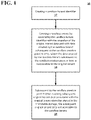
- FIG. 1 shows an example method 10 of creating a sandbox and creating subsequent immutable tenant data according to an implementation of the disclosed subject matter.
- the method 10 may be used by the authorized user associated with an original tenant in the database system to create a sandbox for the original tenant at a point in time.
- the method 10 may be used in connection with the systems shown in FIGS. 3A-6 , as described in detail below.
- the original tenant has original tenant data stored in an immutable storage (e.g., the physical storage shown in FIGS 3A-3B , storage 810 of second computer 800 shown in FIG. 5 , database systems 1200a-d of FIG. 6 , and the like) associated with a tenant identifier.
- the sandbox tenant data as of the sandbox creation point in time is a virtual snapshot of the original tenant data and is accessible to the sandbox tenant.
- the sandbox tenant data is changed without changing the original tenant data, and the original tenant data is changed without changing the sandbox tenant data.
- the snapshot is virtual in that both the original tenant and the sandbox use the same immutable data for data (or versions of data that existed as of the creation of the sandbox).
- a sandbox tenant identifier is created at operation 12.
- the sandbox tenant identifier is created by a database system, such as a server, cloud server, and/or database, or the like.
- the sandbox tenant identifier may be created by the system 100 shown in FIGS. 3A-3B , the server 502 and/or server 504 shown in FIG. 4A , the central component 700 and/or the second computer 800 shown in FIG. 5 , and/or database systems 1200a-1200d shown in FIG. 6 .
- the database system creates a sandbox tenant by associating the sandbox tenant identifier with the virtual snapshot of the original tenant data.
- the sandbox tenant is associated with an authorized user of the database system.
- the sandbox tenant identifier is associated with sandbox data created by the sandbox tenant subsequent to the sandbox creation point in time.
- the sandbox data created by the sandbox tenant subsequent to the sandbox creation point in time is inaccessible to the original tenant.
- the database system ceates subsequent original tenant data associated with the original tenant identifier stored in the immutable storage (e.g., the physical storage shown in FIGS 3A-3B , storage 810 of second computer 800 shown in FIG. 5 , database systems 1200a-d of FIG. 6 , and the like).
- the subsequent original tenant data is created by the database system by an authorized user that is associated with the original tenant. For example, one or more applications controlled by the authorized user associated with the original tenant may perform one or more operations that create the subsequent original tenant data.
- the subsequent immutable original tenant data is not accessible to the sandbox tenant.
- the original tenant accesses original tenant data created both before and after the sandbox creation point in time that is stored in the immutable storage.
- the subsequent immutable original tenant data is written as new original tenant data that does not alter older original tenant data (e.g., the original and the sandbox tenant data) stored in the immutable storage and the original tenant cannot access the data that is created or augmented by the sandbox tenant.
- FIG. 2A shows an example method 20 of receiving a query and operating on data from the immutable storage by dynamic mapping a tenant identifier according to an implementation of the disclosed subject matter.
- the method 20 may be used in connection with the method 10 described above and shown in FIG. 1 .
- the database system may receive a query including a key indicating the sandbox tenant.
- the database system may be a server, cloud server, and/or database, or the like.
- the database system that receives a query may be system 100 shown in FIGS. 3A-3B , server 502 and/or server 504 shown in FIG. 4A , central component 700 and/or a second computer 800 shown in FIG. 5 , and/or database systems 1200a-1200d shown in FIG. 6 .
- the query may be generated, by for example, computer 600 shown in FIG. 5 .
- the database system may operate on data from the immutable storage identified by the key for the sandbox tenant by dynamically mapping a primary key indicating the sandbox tenant to a primary key indicating the original tenant if the primary key identifies a transaction that is part of the virtual sandbox, i.e., the contents of the record being sought was created before the sandbox was created.
- the immutable storage may be the storage shown in FIGS 3A-3B , the storage 810 of second computer 800 shown in FIG. 5 , database systems 1200a-d of FIG. 6 , and the like.
- FIG. 2B shows an example method of retrieving and translating data from the immutable storage, and performing an operation on the translated data according to an implementation of the disclosed subject matter.
- FIG. 2B shows the example operations that may be part of operation 22 of method 20 shown in FIG. 2A and described above.
- the database system may retrieve data from the immutable storage based on the mapped key.
- the database system may be may be system 100 shown in FIGS. 3A-3B , server 502 and/or server 504 shown in FIG. 4A , central component 700 and/or a second computer 800 shown in FIG. 5 , and/or database systems 1200a-1200d shown in FIG. 6
- the immutable storage may be the physical storage shown in FIGS 3A-3B , storage 810 of second computer 800 shown in FIG. 5 , database systems 1200a-d of FIG. 6 , and the like.
- the database system may translate the keys for the data from the immutable storage indicated by the key of the original tenant to a key indicating the sandbox tenant.
- the data remains in the immutable storage and is not duplicated, but the data is associated with the sandbox tenant. That is, the keys of the original tenant are mapped to the keys of the sandbox tenant so that the sandbox tenant may access the data created before the creation of the sandbox may be accessible to users of the sandbox.
- keys for data created by the sandbox tenant are not translated and may point to data in extents that are only accessible to the sandbox tenant and are not available to the original tenant.
- the database system may perform an operation on the translated data at operation 28, and may store data resulting from the performed operation in the immutable storage that is associated with the key of the sandbox tenant at operation 30.
- the database system may, in some implementations, store the data in the immutable storage using a LSM tree data structure.
- Operations on the data associated with the sandbox may include, for example, the manipulation of the data based on one or more functions of the application being tested. That is, the data may be manipulated based on the version of the application being tested and/or a new function that has been added to the application to be tested. However, modifications to that data being tested are not accessible to users associated only with the original tenant.
- the manipulated data is associated with the key of the sandbox tenant, and stored in the immutable storage.
- the example method 20 shown in FIG. 2B may include returning the data from the immutable storage for the sandbox tenant based on the dynamic mapping of the key indicating the sandbox tenant.
- the database system may, in some implementations, receive a query including a key indicating the sandbox tenant and may operate on data from the immutable storage identified by the key for the sandbox tenant.
- the query may be received from an authorized user of the database system that is associated with the sandbox tenant.
- the data may be returned from the immutable storage for the sandbox tenant based on the dynamic mapping of the key indicating the sandbox tenant.
- the database system used in connection with the method 10 may receive an operation to delete the sandbox tenant.
- an authorized user associated with the sandbox tenant may provide a delete request to the database system.
- the database system may remove, from the immutable storage, at least one key associated with the sandbox tenant without changing the original tenant data.
- the removing the at least one key may be performed by removing a key range from the immutable storage without removing physical data stored in the immutable storage. That is, references to the immutable storage for one or more keys of the key range may be removed, but the data previously associated with the removed references may be retained in the immutable storage if there are also keys for that data for the original tenant.
- removing at least one key associated with the sandbox tenant may include removing extent references from the immutable storage for the sandbox tenant data that have original tenant key mappings associated with them. This deletion operation may be performed on the sandbox tenant when there have been no changes to the sandbox tenant data in the immutable storage after the sandbox creation point in time.
- the removing the at least one key by the database system may include removing extent references from the immutable storage for a key range of the sandbox tenant data.
- this deletion operation may be performed when there have been changes to the sandbox tenant data in the immutable storage. This operation may be to replace existing extent references of the original tenant data so as to not include the removed extent references of the sandbox tenant data.
- FIG. 3A shows an example system and method of storing and retrieving data using a virtualization layer according to an implementation of the disclosed subject matter.
- the system 100 may be a single computing device, or may include multiple connected computing devices, and may be, for example, a laptop, a desktop, an individual server, a server cluster, a server farm, or a distributed server system, or may be a virtual computing device or system, or any suitable combination of physical and virtual systems. For simplicity, components such as the processor, short and long term storage, the operating system, much of the database management system are not shown.
- the server system 100 may be part of a computing system and network infrastructure, or may be otherwise connected to the computing system and network infrastructure, including a larger server network which may include other server systems similar to the server system 100.
- the system 100 may be the computer 600, central component 700, and or the second computer 800 shown in FIG. 5 , and/or one or more of the database systems 1200a-1200d shown in FIG. 6 .
- the system 100 may store transactions as immutable versions of given records. Immutable versions of contents of records already stored on the server system may be unchanged until the contents are deleted (if ever) from the server system. That is, a received transaction may create a new version of the contents of the record to be stored in the server system, instead of altering the contents of the record.
- multiple versions of a record e.g., records having different contents
- the use of identical keys for versions of a given record may allow for the changing of data stored in the relational database.
- each version of the physical record may be immutable; i.e., it is either not deleted or is not deleted over an arbitrarily long period of time that may be months, years or decades.
- a later version of a record with an identical key to an earlier version of the record may indicate a change in the data value for that record (i.e., the change in contents of the record).
- a transaction may create a record or delete a record (i.e., create contents or delete contents), but the deletion of the record may not remove the transactions.
- An access layer 105 of the system 100 may have a database storage engine 110, which may accept a query for the database system (e.g., central component 700 shown in FIG. 5 and/or database systems 1200a-1200d shown in FIG. 6 ) from a computing device (e.g., computer 600 and/or a second computer 800 shown in FIG. 5 ).
- the database storage engine 110 may receive a query for an organization within a first namespace of data within a database system.
- the database storage engine 110 may be any suitable combination of hardware and software on the server system 100 for receiving queries for the database system, and retrieving data related to the received query.
- the system 100 may include a virtualization layer 115, which may have an extent reference 120.
- the extent reference 120 may be part of the central component 700 shown in FIG. 5 and/or database systems 1200a-1200d shown in FIG. 6 .
- the extent reference 120 may be any suitable combination of hardware and software on the server system 100 to perform as the virtualization layer 115 between the database storage engine 110 and physical storage 127 (e.g., where extents may be stored as part of extent 130, as described below).
- the physical storage 127 may be semiconductor memory, a solid state drive (SSD), hard disk drive, optical memory, an optical storage device, or any other suitable physical data storage medium, or some combination thereof.
- the extent reference 120 may be for a first namespace.
- the extent reference 120 may receive a query from the database storage engine 110 via the virtualization layer 115 to find data.
- the query may be received from an authorized user of the database system that is associated with at least one tenant.
- the virtualization layer 115 may interpret the query so as to locate the requested data of the query in the physical storage 127 of the system 100 which may store extents. That is, the virtualization layer 115 may retrieve the data requested by the query from the extent 130, and may return the data to the database storage engine 110 which may provide it to the computing device which may the query of the database system.
- FIG. 3B shows retrieving data from the sandbox of a database system by translating the keys for the data according to an implementation of the disclosed subject matter.
- the system 100 of FIG. 3B may be similar to that shown in FIG. 3A , but FIG. 3B may include extent reference 125 as part of the virtualization layer 115, as described in detail below.
- a sandbox may be created for a first (original) tenant (i.e., a first namespace).
- a first namespace i.e., a first namespace
- an authorized user of the database system that is associated with at least the first (original) tenant may issue a command to the database system to create the sandbox (i.e., the second namespace). That is, by using the data of the first namespace, a second namespace may be created, which may form the extent reference 125.
- the data of both the first and second namespaces may be stored in the physical storage 127 of system 100.
- the first and second namespaces may refer entirely or partly to the same stored data.
- the database storage engine 110 may receive a query from the authorized user for data associated with the second namespace.
- the extent reference 125 which may be for the second namespace, may receive the query for the data associated with the second namespace.
- the data stored in the physical storage 127 is the same data.
- the virtualization layer 115 may find the data for the first namespace in the extent 130 based on the query received from the authorized user of the database system.
- the data returned to the extent reference 125 is data for the first namespace.
- the virtualization layer 115 may translate the first namespace data into second namespace data by mapping keys from the first namespace to keys in the second namespace.
- the translated second namespace data may be provided to the database storage engine 110 from the extent reference 125 via the virtualization layer 115.
- the database storage engine 110 may return the second namespace data to the computing device of the authorized database user from which the query was received.
- extent references may be used to determine whether to retrieve pre-sandbox data or post-sandbox data in response to a query.
- the virtual snapshot is a collection of extent references.
- Data created prior to the sandbox may have extent references that point to extents with the original tenant data.
- New sandbox data i.e., subsequent sandbox tenant data that is created after the creation of the sandbox
- Sandbox tenant data (i.e., data associated with a sandbox at the creation of the sandbox) may be associated with extent references that indicate that they contain the sandbox key range.
- the extent references for the sandbox tenant data may point to an extent which has the original keys (i.e., keys to original tenant data that existed at the time of the creation of the sandbox), as well as additional translation information.
- a query may be received by the access layer 105.
- the access layer 105 may determine that the query is for a first namespace for an organization (i.e., for original tenant data associated with an original tenant) based on a predicate in the query.
- queries on behalf of the tenant include a predicate specifying the tenant.
- the predicate indicating the tenant may be explicit, where the predicate may be included before the query retrieves information from the database (e.g., database 1200a, 1200b, 1200c, and/or 1200d shown in FIG. 6 ), or the predicate may be implicit in the way in which a connection is established with a database.
- the access layer 105 may request that the virtualization layer 115 retrieve data requested by the query from the physical storage 127.
- the extent reference 120 of the virtualization layer 115 may point to the extent 130 in the physical storage 127.
- the data stored in the physical storage 127 may be retrieved based on the extent pointed to, and provided in response to the query.
- the access layer 105 may request that the virtualization layer 115 retrieve the data requested by the query from the physical storage 127 based on a determination that the predicate in the query is associated with the second namespace (i.e., the data associated with the sandbox tenant).
- the extent reference 125 which includes the predicate in the query (i.e., for the sandbox key range), may point to the extent 130 in the physical storage 127, which has the original keys (e.g., for the data for the first namespace).
- the returned data of the first namespace from the extent 130 is translated by using the translation information included with the extent reference 125. That is, the returned data for the first namespace may be translated to second namespace data with the translation information included with the extent reference 125.
- the data for the second namespace (e.g., data that is associated with the extent reference 125) may be returned to the access layer 105 in response to the query received by the access layer 105, as described in detail above in connection with FIG. 3B .
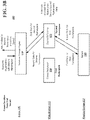
- FIGS. 4A-4B show an example of a system 500 that may be used in connection with forming a sandbox according to an implementation of the disclosed subject matter.
- FIGS. 4A-4B show a remapping of a tenant with multiple keys according to an implementation of the disclosed subject matter.
- the system 500 may be a database system, server system, cloud server system, or the like.
- the system 500 may include server 502, server 504, store 510, and catalog 520.
- the servers 502, 504 may have the same persistence, or may have different a different persistence from one another.
- the store 510 which may be shared by the servers 502 and 504, may be any suitable combination of hardware and software on the system 500 for storing key ranges for data in extents associated with the server 502 and/or the server 504.
- the store 510 may include extent 511, which may be associated with server 502, and extent 512, which may be associated with server 504.
- the catalog 520 may be may be any suitable combination of hardware and software on the system 500 for storing data extents and data extent references.
- server 502 may be associated with the extent 511 in store 510, the extent 511 having tenant IDs of 10, 11, 62, and 98, where each tenant ID number has a key that starts with the tenant ID number.
- the tenant ID of 62 may have multiple keys in a key range, where the keys all start with 62. That is, in this example, 62 may be the leading portion of a key, with a complete key being made of different components, and may be the tenant ID.
- the server 504 may be associated extent 512, having tenant IDs 33, 34, 44, and 66, where each tenant ID number has a key that starts with the tenant ID number.
- the extent 511 associated with the server 502 may have a key range of key ([first key], [last key]) of key (10, 98), and the extent 512 associated with the second server 504 may have a key range of key (33, 66).
- data extents 522 may map to the data extents 511 and 512 for the servers 502 and 504.
- the ID for the extent 511 may be 0x21
- the key start may be 10 (i.e., which matches that of the extent 511 in the store 510)
- the key end may be 98 (i.e., which matches that of the extent 511 in the store 510).
- Data extent references 524 may be references to the data extents (e.g., data extents 522), and may include information about an associated server (e.g., server 502 or 504).
- Row 525 of the data extent references 524 may include similar information for ID 0x21 of the data extents 522, but may include the EID (extent ID) as 0x21, and may indicate that the server having the key start of 10 and the key end of 98 is server 502.
- the data extent references 524 show a state of the extents prior to having tenant ID 62 of the extent 511 associated with the server 502 be sandboxed as tenant ID 63.
- the data extent references 524 may reflect the changes to server 504.
- the extent 512 i.e., the extent having EID for 0x88
- the extent 512 may be split into two key ranges.
- the data extent references 524 may be updated so that the extent of row 526 (i.e., the extent 512) may have a key start of 33 and a key end of 44 (i.e., a key range of (33, 44), and the extent of row 528 (i.e., the extent 512) may have a key start of 66 and a key end of 66 (i.e., a key range of (66, 66)). That is, key range 33-44 of the extent 512 is in a first segment, and the key range starting and ending with key 66 is a second segment. As shown in FIG. 4B , the server 504 may point to the key range of (33, 44), as well as point to the key range of (66, 66), in extent 512.
- a row 527 may be inserted between row 526 and row 528 of the data extent reference 524.
- Row 527 may have the extent 511 (i.e., the extent having the extent ID of 0x21, much like row 525 for server 502), and may have a key start of 63 and a key end of 63, and may indicate the mapping of the tenant ID 62 to the tenant ID 63.
- the data extent reference 524 may include the key range (10, 98) associated with the server 502, and the key ranges (33, 44), (63, 63), and (66, 66) associated with the server 504. That is, FIG. 4A may show the state of the data extent references 524 before the mapping of tenant 62 to tenant 63, and FIG.
- the server 504 may point to the key range of (33, 44) and the key range (66, 66) of the extent 512, as well as the key range (62, 62) of the extent 511.
- FIG. 5 is an example computer 600 suitable for implementing implementations of the presently disclosed subject matter.
- the computer 600 may be a single computer in a network of multiple computers.
- the computer 600 may communicate with a central or distributed component 700 (e.g., server, cloud server, database, cluster, application server, etc.).
- the central component 700 may communicate with one or more other computers such as the second computer 800, which may include a storage device 810.
- the second computer 800 may be a server, cloud server, or the like.
- the storage 810 may use any suitable combination of any suitable volatile and non-volatile physical storage mediums, including, for example, hard disk drives, solid state drives, optical media, flash memory, tape drives, registers, and random access memory, or the like, or any combination thereof.
- Data may be stored in any suitable format in, for example, the storage 810, using any suitable filesystem or storage scheme or hierarchy.
- the storage 810 may store data using a log structured merge (LSM) tree with multiple levels.
- LSM log structured merge
- the storage may be organized into separate log structured merge trees for each instance of a database for a tenant.
- contents of all records on a particular server or system may be stored within a single log structured merge tree, in which case unique tenant identifiers associated with versions of records may be used to distinguish between data for each tenant as disclosed herein. More recent transactions may be stored at the highest or top level of the tree and older transactions may be stored at lower levels of the tree.
- the most recent transaction or version for each record i.e., contents of each record
- the information obtained to and/or from a central component 700 may be isolated for each computer such that computer 600 may not share information with computer 800. Alternatively or in addition, computer 600 may communicate directly with the second computer 800.
- the computer 600 includes a bus 610 which interconnects major components of the computer 600, such as a central processor 640, a memory 670 (typically RAM, but which may also include ROM, flash RAM, or the like), an input/output controller 680, a user display 620, such as a display or touch screen via a display adapter, a user input interface 660, which may include one or more controllers and associated user input or devices such as a keyboard, mouse, WiFi/cellular radios, touchscreen, microphone/speakers and the like, and may be closely coupled to the I/O controller 680, fixed storage 630, such as a hard drive, flash storage, Fibre Channel network, SAN device, SCSI device, and the like, and a removable media component 650 operative to control and receive an optical disk, flash drive, and the like.
- a bus 610 which interconnects major components of the computer 600, such as a central processor 640, a memory 670 (typically RAM, but which may also include ROM, flash RAM, or the like
- the bus 610 enable data communication between the central processor 640 and the memory 670, which may include read-only memory (ROM) or flash memory (neither shown), and random access memory (RAM) (not shown), as previously noted.
- the RAM can include the main memory into which the operating system and application programs are loaded.
- the ROM or flash memory can contain, among other code, the Basic Input-Output system (BIOS) which controls basic hardware operation such as the interaction with peripheral components.
- BIOS Basic Input-Output system
- Applications resident with the computer 600 can be stored on and accessed via a computer readable medium, such as a hard disk drive (e.g., fixed storage 630), an optical drive, floppy disk, or other storage medium 650.
- the fixed storage 630 may be integral with the computer 600 or may be separate and accessed through other interfaces.
- a network interface 690 may provide a direct connection to a remote server via a telephone link, to the Internet via an internet service provider (ISP), or a direct connection to a remote server via a direct network link to the Internet via a POP (point of presence) or other technique.
- the network interface 690 may provide such connection using wireless techniques, including digital cellular telephone connection, Cellular Digital Packet Data (CDPD) connection, digital satellite data connection or the like.
- CDPD Cellular Digital Packet Data
- the network interface 690 may enable the computer to communicate with other computers via one or more local, wide-area, or other networks, as shown in FIG. 6 .
- FIG. 6 shows an example network arrangement according to an implementation of the disclosed subject matter.
- Each of database systems 1200 may be operable to host multiple instances of a database, where each instance is accessible only to users associated with a particular tenant.
- Each of the database systems may constitute a cluster of computers along with a storage area network (not shown), load balancers and backup servers along with firewalls, other security systems, and authentication systems.
- Some of the instances at any of systems 1200 may be live or production instances processing and committing transactions received from users or from computing elements (not shown) for ingesting and providing data for storage in the instances.
- One or more of the database systems 1200a-1200d may create a sandbox for an original tenant at any time.
- one or more authorized users of the database systems 1200a-1200d that are associated with the original tenant may request that a sandbox be created by one of the database systems 1200a-1200d.
- the system may include at least one storage device, such as in FIG. 6 .
- the storage may include memory 670, fixed storage 630, removable media 650, a storage device included with the central component 700 and/or the second computer 800, and/or one or more storage devices associated with one or more of the database systems 1200a-1200d.
- the original tenant may have original tenant data stored in an immutable storage of the at least one storage device associated with an original tenant identifier.
- the original tenant data as of the sandbox creation point in time may be used to create a virtual snapshot of the original tenant data accessible by a sandbox tenant.
- the new or updated sandbox tenant data can be stored in the storage device or elsewhere (e.g., such as a cache storage system, networked storage device, or the like) and can be changed without changing the original tenant data that existed as of the time of the creation of the sandbox, and the original tenant data can be changed or updated without changing the sandbox tenant data.
- neither the sandbox tenant nor the original tenant may alter the data in the virtual snapshot as subsequent updates for the sandbox tenant and the original tenant may be stored separately in different portions of the LSM storage.
- the virtual snapshot may be created by noting a time stamp or other time identifier as of the creation of the sandbox tenant. Thereafter, both the sandbox tenant and original tenant will interpret primary key requests for versions of the data before the time stamp by accessing the appropriate version based on the key in the pool of the data stored before the time stamp. Keys for the respective tenants accessing data created or updated after the time stamp will be interpreted to access the appropriate data created by only the sandbox tenant or the original tenant.
- each transaction in the database may have a unique transaction number associated with it that is monotonically increasing for each subsequent transaction and the system may note the most recently created transaction identifier in lieu of the time stamp.
- the one or more servers may create a sandbox tenant identifier, and may create the sandbox tenant by associating the sandbox tenant identifier with the virtual snapshot of the original tenant data and with sandbox data created by the sandbox tenant subsequent to the sandbox creation point in time.
- the sandbox data created by the sandbox tenant subsequent to the sandbox creation point in time may be inaccessible to the original tenant.
- the systems shown in FIGS. 5-6 may create subsequent original tenant data associated with the original tenant identifier stored in the immutable storage of the storage device. This subsequent original tenant data may not be accessible to the sandbox tenant.
- the original tenant may access original tenant data created both before and after the sandbox creation point in time that is stored in the immutable storage, and the subsequent sandbox tenant data may be created as new tenant data that does not alter other tenant data stored in the immutable storage.
- the one or more servers of the systems shown in FIGS. 5-6 may receive a query including a key indicating the sandbox tenant operating on data from the immutable storage identified by the key for the sandbox tenant by dynamically mapping the key indicating the sandbox tenant to a key indicating the original tenant.
- the keys may include a time stamp or sequence indicator as described above.
- the time stamp or sequence indicator may be examined by the database system to determine if the time stamp or sequence identifier indicates that the sandbox tenant is seeking to access data created before the creation of the sandbox tenant. In that case, the key is dynamically mapped to the appropriate data that may be accessed by both the original tenant and the sandbox tenant.
- the one or more servers of the systems shown in FIGS. 5-6 may receive the data from the immutable storage for the sandbox tenant from the at least one storage device (e.g., the storage device associated with central component 700, the second computer 800, and/or the database systems 1200a-1200d) based on the dynamic mapping of the key indicating the sandbox tenant.
- the at least one storage device e.g., the storage device associated with central component 700, the second computer 800, and/or the database systems 1200a-1200d
- the one or more servers of the systems shown in FIGS. 5-6 may operate on data so as to retrieve data from the immutable storage based on the mapped key.
- the servers may translate the data from the immutable storage indicated by the key of the original tenant to data of the key indicating the sandbox tenant and perform an operation on the translated data.
- the data resulting from the performed operation may be in the immutable storage of a device that is associated with the key of the sandbox tenant, such as the storage device associated with central component 700, second computer 800, and/or one or more of the database systems 1200a-1200d.
- the one or more servers of the systems shown in FIGS. 5-6 may receive a query (e.g., from computer 600 shown in FIG. 5 , or the like) including a key indicating the original tenant, and may operate on data from the immutable storage of the at least one storage device identified by the key for the original tenant.
- the one or more servers receives the data from the immutable storage from the at least one storage device for the sandbox tenant based on the dynamic mapping of the key indicating the sandbox tenant.
- the servers of FIGS. 5-6 may receive (e.g., from computer 600 shown in FIG. 5 , or the like) an operation to delete the sandbox tenant.
- the one or more servers of FIGS. 5-6 may remove, from the immutable storage of the at least one storage device (e.g., a storage device associated with central component 700, the second computer 800, and/or the database systems 1200a-1200d), the key associated with the sandbox tenant without changing the original tenant data.
- the at least one storage device e.g., a storage device associated with central component 700, the second computer 800, and/or the database systems 1200a-1200d
- the server of FIGS. 5-6 may remove a key range from the immutable storage (e.g., a storage device associated with central component 700, the second computer 800, and/or the database systems 1200a-1200d) without removing physical data stored in the immutable storage.
- the server of FIGS. 5-6 may remove extent references from the immutable storage for the sandbox tenant data that have tenant mapping associated with them when there have been no changes to the sandbox tenant data in the immutable storage after the sandbox creation point in time.
- 5-6 may remove extent references from the immutable storage for a key range of the sandbox tenant data when there have been changes to the sandbox tenant data in the immutable storage so as to replace existing extent references of the original tenant data so as to not include the removed extent references of the sandbox tenant data.
- the one or more servers shown in FIGS. 5-6 may store the data in the immutable storage of the at least one storage device (e.g., a storage device associated with central component 700, the second computer 800, and/or the database systems 1200a-1200d) using a log-structured merge tree data structure.
- the at least one storage device e.g., a storage device associated with central component 700, the second computer 800, and/or the database systems 1200a-1200d
- a log-structured merge tree data structure e.g., a storage device associated with central component 700, the second computer 800, and/or the database systems 1200a-1200d
- the systems and methods of the disclosed subject matter may be for single tenancy and/or multi-tenancy systems.
- Multi-tenancy systems may allow various tenants, which may be, for example, users, groups of users, or organizations, to access their own records on the server system through software tools or instances on the server system that may be shared among the various tenants.
- the contents of records for each tenant may be part of a database for that tenant. Contents of records for multiple tenants may all be stored together within the same server system, but each tenant may only be able to access contents of records which belong to, or were created by, that tenant.
- This may allow a server system to enable multi-tenancy without having to store each tenants' contents of records separately, for example, on separate servers or server systems.
- the database for a tenant may be, for example, a relational database, hierarchical database, or any other suitable database type. All records stored on the server system may be stored in any suitable structure, including, for example, a LSM tree.
- a record as disclosed herein may be identified by a key-value pair in the instance of a multi-tenant system.
- the databases may not have notions of tenancy.
- Tenancy in the databases may be created by one or more virtual overlays, so that a user may view, access, and/or perform operations for a tenancy associated with an authorized user of a database system.
- the value may be, for example, the contents of a row of a table of a relational database, an identification of a row in a table of a relational database, or any other suitable value.
- the key may be an identifier for the record, and may in any suitable form, such as, for example, an alphanumeric sequence. Portions of the key may provide information about the contents of the record.
- a portion of the key may be a tenant identifier, which may uniquely identify the tenant to whom the contents of the record belongs.
- Other portions of the key may identify, for example, a table number and identification of a row, for example, when the value of a record is the contents of a row, or table number, index number on the table, and an identification of indexed columns when the value is the identification of a row.
- a multitenant system may have various tenant instances on server systems distributed throughout a network with a computing system at each node.
- the live or production database instance of each tenant may only have its transactions processed at one computer system.
- the computing system for processing the transactions of that instance may also process transactions of other instances for other tenants.
- implementations of the presently disclosed subject matter may include or be implemented in the form of computer-implemented processes and apparatuses for practicing those processes. Implementations also may be implemented in the form of a computer program product having computer program code containing instructions implemented in non-transitory and/or tangible media, such as floppy diskettes, CD-ROMs, hard drives, USB (universal serial bus) drives, or any other machine readable storage medium, wherein, when the computer program code is loaded into and executed by a computer, the computer becomes an apparatus for practicing implementations of the disclosed subject matter.
- Implementations also may be implemented in the form of computer program code, for example, whether stored in a storage medium, loaded into and/or executed by a computer, or transmitted over some transmission medium, such as over electrical wiring or cabling, through fiber optics, or via electromagnetic radiation, wherein when the computer program code is loaded into and executed by a computer, the computer becomes an apparatus for practicing implementations of the disclosed subject matter.
- the computer program code segments configure the microprocessor to create specific logic circuits.
- a set of computer-readable instructions stored on a computer-readable storage medium may be implemented by a general-purpose processor, which may transform the general-purpose processor or a device containing the general-purpose processor into a special-purpose device configured to implement or carry out the instructions.
- Implementations may be implemented using hardware that may include a processor, such as a general purpose microprocessor and/or an Application Specific Integrated Circuit (ASIC) that implements all or part of the techniques according to implementations of the disclosed subject matter in hardware and/or firmware.
- the processor may be coupled to memory, such as RAM, ROM, flash memory, a hard disk or any other device capable of storing electronic information.
- the memory may store instructions adapted to be executed by the processor to perform the techniques according to implementations of the disclosed subject matter.
Description
- Test systems are typically formed for applications, and are separate from production systems. Such systems, which can be referred to as "sandboxes," may be used to test new features and versions of the applications. In known systems, live production data cannot be used for sandboxing because the testing would corrupt the production data. Therefore, separate copies of customer data are made that are used for testing and development. Creating the separate copies of the database for a typical sandbox system is slow, consumes a significant amount of computational resources, is prone to error and can take up substantial data storage resources. In many cases, it is not practical to copy all of data in a single transaction, so the copied data may not be transactionally consistent. In that case, the testing of the application may not be successful in determining the operational functionality of the features of the application, because the sandbox data being used in testing may not be accurate. In some cases, the inconsistent data can be reconciled before the sandbox can be used, which can be time consuming and require substantial processor and memory resources.
-
US 2014/0379677 A1 describes a network-based system, which comprises a server machine, a production database and a test database. The server machine comprises a communication module, a production database module, which communicates with the production database to process requests related to the production database received by the communication module, and a test database module, which communicates with the test database to process requests received by the communication module related to the test database. The test database module also communicates with the production database to read data. Requests to the system are received and processed by the communication module, which also determines whether the request is a test request or a request to the production database. According to this document, a test query is carried out both by the production database and the test database and the records found in the queries both in the production database and in the test database are returned. If a record is to be modified in response to a test request, the record is modified in the test database and a modification of the production database is prevented. -
US 2016/0048844 A1 describes license management in a multi-tenant database, wherein tenants have a sandbox that can be utilized with the multitenant environment. The sandbox is on a different logical database than the production database. The sandbox and the production organization, i.e. the tenant to which this sandbox relates, act as independent organizations in the multi-tenant environment. At the time of creating or refreshing the sandbox, a copy of the production organization as of the time of creation is made. After this point in time, the sandbox organization and the production organization of are isolated so that operations performed in the sandbox do not affect the production organization and vice versa. In order to make licenses of the production organization available to the sandbox, it is proposed to fetch the license data through a messaging service that makes a cross-instance call, e.g. using the Simple Object Access Protocol (SOAP). - The accompanying drawings, which are included to provide a further understanding of the disclosed subject matter, are incorporated in and constitute a part of this specification. The drawings also illustrate implementations of the disclosed subject matter and together with the detailed description serve to explain the principles of implementations of the disclosed subject matter. No attempt is made to show structural details in more detail than may be necessary for a fundamental understanding of the disclosed subject matter and various ways in which it may be practiced.
-
FIG. 1 shows an example method of creating a sandbox for sandbox tenant data and creating subsequent immutable original tenant data for an original tenant according to an implementation of the disclosed subject matter. -
FIG. 2A shows an example method of receiving a query and operating on data from the immutable storage by dynamic mapping a tenant identifier according to an implementation of the disclosed subject matter. -
FIG. 2B shows an example method of retrieving and translating data from the immutable storage, and performing an operation on the translated data according to an implementation of the disclosed subject matter. -
FIG. 3A shows an example system and method of storing and retrieving data using a virtualization layer according to an implementation of the disclosed subject matter. -
FIG. 3B shows retrieving data from the sandbox of a database system by translating the data according to an implementation of the disclosed subject matter. -
FIGS. 4A-4B show an example of a system architecture that may be used in connection with a sandbox according to an implementation of the disclosed subject matter. -
FIG. 5 shows a computer according to an implementation of the disclosed subject matter. -
FIG. 6 shows a network configuration according to an implementation of the disclosed subject matter. - The object of the invention is solved by the features of the independent claims. Further embodiments are the subject-matter of the dependent claims.
- Implementations of the disclosed subject matter can create and run a sandbox based on input from one or more authorized users that are associated with one or more tenants of a database system without having to duplicate production data or operate on duplicated production data. Such a sandbox can be established more quickly than known sandboxes at much lower cost in terms of processor resources, data storage and persistence resources, and/or datapath (e.g., communication network) resources. Since the disclosed system reads production data, it is inherently accurate and no consistency checks or other corrective measures need to be taken with respect to the data being tested. It can also produce more accurate test results for an application because the integrity of the data being tested can be better than in known sandbox implementations.
- In implementations of the sandbox, one or more authorized users that are associated with one or more tenants of a database system create a sandbox tenant for a database. An authorized user of the database system may be a user that has security access rights to one or more tenants of the database system. For example, the user may provide a password and/or other information (e.g., security code, bioinformatics, or the like) to the database system, which may determine whether the user is an authorized user based on the provided information. If the provided information matches stored information of the database system, the user may be determined to be an authorized user and may be granted access to the database system.
- The sandbox tenant may have access to data associated with sandbox tenant keys, while an original (non-sandbox) tenant has access to data associated with original tenant keys. The range of keys associated with a tenant (e.g., an original tenant, a sandbox tenant, or the like) can be all or part of a tenant namespace. Ordinarily, one tenant has no access to another tenant's namespace. However, in implementations of the described subject matter, a combination of hardware and software can create a correspondence between certain sandbox tenant keys and original tenant keys to provide the sandbox tenant read access to point in time data associated with the original tenant. In this way, the sandbox tenant can use original tenant data without having to copy the original tenant data to the sandbox tenant's namespace. This point in time data can be used by the sandbox to test the application.
- New transaction data generated by the sandbox tenant is written to the sandbox tenant namespace not accessible to the original tenant. New transaction data generated by the original tenant is written to original tenant namespace not accessible to the sandbox tenant. In this way, new sandbox tenant data does not corrupt original tenant (production) data, and new original tenant data (e.g., which is referred to as subsequent immutable original tenant data) does not corrupt the test data being read and written by the sandbox to test the application. An implementation can be used with a relational database that stores persistent contents of records, e.g., in a Log Structured Merge (LSM) tree.
- In accordance with this arrangement, authorized users associated with one or more tenants of the database systems of the disclosed implementations can more quickly create and run sandboxes that use only a fraction of the data storage and persistence resources, processor resources, and/or datapath (e.g., communication network) resources used by traditional sandbox systems.
- In general, applications can be run on servers for production systems, and test systems may be separate from the production systems. The test systems may be used to test new features and/or versions of the applications. The production system applications may be run on a company's or an organization's servers (i.e., running an application "on premises"), or by running an application in a cloud-based computing environment (e.g., where the servers are remote from the company's or organization's servers).
- Implementations of the disclosed subject matter provide systems and methods for authorized users associated with one or more tenants of a database system to create sandboxes, which use at least a portion company data, organization data, and/or customer data (i.e., the production data) for testing and development by creating sandbox data based on the production data, without altering the production data. As used throughout, customer data may refer to any portion of company data and/or organization data.
- One or more features of the application may be tested using the sandbox data. Once the features of the application have been tested, the sandbox can be deleted without impacting the production data. The sandbox may be deleted by removing references (e.g., pointers) to the sandbox data. The removal of the references in a sandbox deletion operation may be instantaneous, and utilizes fewer processor, data storage, and/or datapath resources than with traditional sandboxing systems. In some implementations, the references of the sandbox data may not be copied forward in a data merge operation to maintain the references, so the sandbox may be effectively removed, as there are no longer any active references to the sandbox.
- With traditional systems and methods, the process of sandboxing customer data involves creating a new tenant for the sandbox on a destination database instance. The tenant data is copied to the target database instance while the tenant is "live" on the source instance. With the traditional systems and methods, it is necessary to run a consistency check to determine if copied data is transactionally consistent. Upon completion of the consistency check, the tenant can be activated on the destination database instance, which may include, for example, the sandbox.
- The disclosed implementations overcome important limitations in traditional sandboxing technology. More specifically, creating a traditional sandbox is slow, in that it takes time to copy all of the necessary data, and check to see if the copied data is consistent with the original data set. Such traditional systems and methods are also resource-heavy (i.e., they require a substantial amount of computing, datapath, network, and/or storage resources to copy an entire set of data), and error prone. For example, the data may not be copied correctly, may be missing portions of data, data may be corrupted, or the like. That is, creating a sandbox using traditional systems and methods involves copying all the rows for the tenant into a new sandboxed tenant. Copying row-by-row may be slow and resource intensive, on both the source and the target database, and it may effectively double the tenant's storage. It is also not practical to copy all of a tenant's data in a single transaction, so there may be a complicated process of reconciling inconsistent data before the sandbox can be made available to the customer.
- In implementations of the disclosed subject matter, systems and methods are provided that may more quickly generate a sandbox and use substantially less storage space than with traditional sandboxing systems. The systems and methods of the disclosed subject matter generate a sandbox with data that may be fully consistent without having to perform error checking, as may need to be performed when using standard sandboxing methods.
- As described in detail below, an implementation of the disclosed subject matter may implement a sandbox using an immutable storage such as a LSM tree, a single key space rooted by a tenant identifier (i.e., "tenant ID"), and by using persistence virtualization. The persistence may be made up of extents. As understood in the art and as used herein, an "extent" refers to a region of storage, typically continuous within a storage medium, which may be used to store data. Extents may be immutable and may be ordered by key. That is, the extents may be immutable in that they may not be modified after they are created, such that the region and data associated with the extent within the storage medium are not updated, but may be deleted in the future. For example, the extents that are no longer referred to in sandbox data may be deleted, as the references may not be copied forward in a data merge operation to maintain the references. That is, the sandbox and its extents may be effectively removed, as there are no longer any active references to the sandbox. New data can be added to the database, and new extents can be created. Extents can be stored in a shared storage that may be analogous to a distributed filesystem.
- An extent reference may be used as a logical reference to a physical extent that is stored in physical storage (e.g., a storage device), and may be used to virtualize access to the physical storage. To create a sandbox according to the systems and methods of the disclosed subject matter, an authorized user of the database system that is associated with the source tenant may request that a new extent reference may be added for each extent that contains keys for the source tenant, with instructions to translate the tenant IDs in a key range from the source (i.e., an original tenant) to the target (i.e., a new sandbox tenant). The translation can map certain read operations issued by requests generated from users associated with the new sandbox tenant onto original tenant data as of a point in time. The point in time data can be delineated by the key range. Subsequent transactions written by the original tenant may have no effect on the point in time data being referenced for the transactions. Write operations by the sandbox tenant may be stored under a different key (the sandbox tenant key) than the original tenant data, so sandbox write operations do not corrupt any original data. This allows for quick formation of a sandbox, as it only requires metadata changes and copying of metadata, and no underlying data needs to be copied. This may be desirable over typical sandbox systems, which require substantial resources to copy tenant data and store it in a new location for a sandbox, and determine if the data has been accurately copied. The resources utilized in traditional sandboxing systems and methods may include increased storage device capacity, processor overhead in managing the copying and determining if it was accurately performed, time needed to copy and to check the accuracy, and the like.
- In an implementation of the disclosed subject matter, a method is provided for an authorized user of a database system that is associated with an original tenant to create a sandbox for the original tenant at a point in time, the original tenant having original tenant data stored in an immutable storage associated with an original tenant identifier, the original tenant data as of the sandbox creation point in time being a virtual snapshot of the original tenant data accessible by a sandbox tenant, where the sandbox tenant data may be changed without changing the original tenant data, and the original tenant data may be changed without changing the sandbox tenant data. The method includes creating a sandbox tenant identifier. The virtual snapshot is such that the original tenant data is made available to a sandbox tenant so that the sandbox tenant accesses the original tenant data in the same manner as if a copy of the original tenant data was made, without copying underlying data. A sandbox tenant may be created at the request of the associated authorized user by associating the sandbox tenant identifier with the virtual snapshot of the original tenant data and with sandbox data created by the sandbox tenant subsequent to the sandbox creation point in time. The sandbox data created and/or modified by the sandbox tenant subsequent to the sandbox creation point in time is inaccessible to the original tenant.
- Subsequent to the sandbox creation point in time, new or updated original tenant data may be created and are associated with the original tenant identifier stored in the immutable storage. This subsequent new or updated original tenant data is not accessible to users who are accessing the sandbox tenant. Users of the original tenant access tenant data created both before and after the sandbox creation point in time that is stored in the immutable storage. That is, authorized users associated with the original tenant can read and write data the same way as they could before the sandbox was created. The subsequent original tenant data is written as new or updated original tenant data and this new or updated data does not alter older original tenant data stored in the immutable storage.
- In an implementation of the disclosed subject matter, a system having at least one storage device is provided so that one or more authorized users associated with an original tenant in the database system may create a sandbox for the original tenant at a point in time. This is done by creating a new sandbox tenant identifier. The original tenant may have tenant data stored in an immutable storage of the at least one storage device associated with the original tenant identifier. The original tenant data, as of the sandbox creation point in time, may be used to provide a virtual snapshot of immutable original tenant data that the implementation makes accessible to a sandbox tenant. That is, the original tenant data may be made available to a sandbox tenant so that the sandbox tenant can access the original tenant data in the same manner as if a copy of the original tenant data was made. Similarly, the original tenant may also access the same original tenant data. Neither can change this virtual snapshot, as the underlying data of the virtual snapshot is immutable.
- However, changes and/or additions submitted either to the original tenant data or the sandbox tenant data are not stored so as to overwrite or otherwise replace the original tenant data. Subsequently, changes and/or additions made by authorized users associated with either the original tenant or the snapshot tenant can be stored without changing the virtual snapshot. Rather, data for the original tenant is stored in immutable extents and data for the sandbox tenancy may be stored in separate immutable extents as disclosed in further detail herein. Mechanisms, such as pointers or the like, to these additional extents may permit the original tenant data to be changed and/or augmented without changing the sandbox tenant data. The system creates a sandbox tenant identifier, and creates the sandbox tenant by associating the sandbox tenant identifier with access to the virtual snapshot of the tenant data and with data created by authorized users of the sandbox tenant (e.g., in an application and/or with the database system, or the like) subsequent to the sandbox creation point in time. The data created by the sandbox tenant and/or the authorized user of the database system associated with the sandbox tenant subsequent to the sandbox creation point in time is inaccessible to the original tenant. Subsequent to the sandbox creation point in time, the system creates immutable tenant data associated with the original tenant identifier stored in the immutable storage of the at least one storage device. This subsequent immutable original tenant data is not accessible to the sandbox tenant. The original tenant and/or the authorized user of the database system associated with the original tenant may access original tenant data created both before and after the sandbox creation point in time that is stored in the immutable storage. The subsequent immutable original tenant data is created as new original tenant data that does not alter other tenant data (e.g., the original and the sandbox tenant data) stored in the immutable storage. The authorized user associated with the original tenant of the database system has access to the subsequent immutable original tenant data and the new original tenant data.
-
FIG. 1 shows anexample method 10 of creating a sandbox and creating subsequent immutable tenant data according to an implementation of the disclosed subject matter. - In particular, the
method 10 may be used by the authorized user associated with an original tenant in the database system to create a sandbox for the original tenant at a point in time. Themethod 10 may be used in connection with the systems shown inFIGS. 3A-6 , as described in detail below. The original tenant has original tenant data stored in an immutable storage (e.g., the physical storage shown inFIGS 3A-3B ,storage 810 ofsecond computer 800 shown inFIG. 5 ,database systems 1200a-d ofFIG. 6 , and the like) associated with a tenant identifier. In themethod 10, the sandbox tenant data as of the sandbox creation point in time is a virtual snapshot of the original tenant data and is accessible to the sandbox tenant. The sandbox tenant data is changed without changing the original tenant data, and the original tenant data is changed without changing the sandbox tenant data. The snapshot is virtual in that both the original tenant and the sandbox use the same immutable data for data (or versions of data that existed as of the creation of the sandbox). - A sandbox tenant identifier is created at
operation 12. The sandbox tenant identifier is created by a database system, such as a server, cloud server, and/or database, or the like. For example, the sandbox tenant identifier may be created by thesystem 100 shown inFIGS. 3A-3B , theserver 502 and/orserver 504 shown inFIG. 4A , thecentral component 700 and/or thesecond computer 800 shown inFIG. 5 , and/ordatabase systems 1200a-1200d shown inFIG. 6 . - At operation 14, the database system creates a sandbox tenant by associating the sandbox tenant identifier with the virtual snapshot of the original tenant data. The sandbox tenant is associated with an authorized user of the database system. The sandbox tenant identifier is associated with sandbox data created by the sandbox tenant subsequent to the sandbox creation point in time. The sandbox data created by the sandbox tenant subsequent to the sandbox creation point in time is inaccessible to the original tenant.
- At
operation 16, subsequent to the sandbox creation point in time, the database system ceates subsequent original tenant data associated with the original tenant identifier stored in the immutable storage (e.g., the physical storage shown inFIGS 3A-3B ,storage 810 ofsecond computer 800 shown inFIG. 5 ,database systems 1200a-d ofFIG. 6 , and the like). The subsequent original tenant data is created by the database system by an authorized user that is associated with the original tenant. For example, one or more applications controlled by the authorized user associated with the original tenant may perform one or more operations that create the subsequent original tenant data. The subsequent immutable original tenant data is not accessible to the sandbox tenant. That is, the original tenant accesses original tenant data created both before and after the sandbox creation point in time that is stored in the immutable storage. The subsequent immutable original tenant data is written as new original tenant data that does not alter older original tenant data (e.g., the original and the sandbox tenant data) stored in the immutable storage and the original tenant cannot access the data that is created or augmented by the sandbox tenant. -
FIG. 2A shows anexample method 20 of receiving a query and operating on data from the immutable storage by dynamic mapping a tenant identifier according to an implementation of the disclosed subject matter. In some implementations, themethod 20 may be used in connection with themethod 10 described above and shown inFIG. 1 . Atoperation 21, the database system may receive a query including a key indicating the sandbox tenant. The database system may be a server, cloud server, and/or database, or the like. For example, the database system that receives a query may besystem 100 shown inFIGS. 3A-3B ,server 502 and/orserver 504 shown inFIG. 4A ,central component 700 and/or asecond computer 800 shown inFIG. 5 , and/ordatabase systems 1200a-1200d shown inFIG. 6 . The query may be generated, by for example,computer 600 shown inFIG. 5 . - At
operation 22, the database system may operate on data from the immutable storage identified by the key for the sandbox tenant by dynamically mapping a primary key indicating the sandbox tenant to a primary key indicating the original tenant if the primary key identifies a transaction that is part of the virtual sandbox, i.e., the contents of the record being sought was created before the sandbox was created. The immutable storage may be the storage shown inFIGS 3A-3B , thestorage 810 ofsecond computer 800 shown inFIG. 5 ,database systems 1200a-d ofFIG. 6 , and the like. -
FIG. 2B shows an example method of retrieving and translating data from the immutable storage, and performing an operation on the translated data according to an implementation of the disclosed subject matter. In particular,FIG. 2B shows the example operations that may be part ofoperation 22 ofmethod 20 shown inFIG. 2A and described above. Atoperation 24, as shown inFIG. 2B , the database system may retrieve data from the immutable storage based on the mapped key. As described above, the database system may be may besystem 100 shown inFIGS. 3A-3B ,server 502 and/orserver 504 shown inFIG. 4A ,central component 700 and/or asecond computer 800 shown inFIG. 5 , and/ordatabase systems 1200a-1200d shown inFIG. 6 , and the immutable storage may be the physical storage shown inFIGS 3A-3B ,storage 810 ofsecond computer 800 shown inFIG. 5 ,database systems 1200a-d ofFIG. 6 , and the like. - At
operation 26, the database system may translate the keys for the data from the immutable storage indicated by the key of the original tenant to a key indicating the sandbox tenant. For this translation operation, the data remains in the immutable storage and is not duplicated, but the data is associated with the sandbox tenant. That is, the keys of the original tenant are mapped to the keys of the sandbox tenant so that the sandbox tenant may access the data created before the creation of the sandbox may be accessible to users of the sandbox. However, keys for data created by the sandbox tenant are not translated and may point to data in extents that are only accessible to the sandbox tenant and are not available to the original tenant. - The database system may perform an operation on the translated data at
operation 28, and may store data resulting from the performed operation in the immutable storage that is associated with the key of the sandbox tenant atoperation 30. The database system may, in some implementations, store the data in the immutable storage using a LSM tree data structure. Operations on the data associated with the sandbox may include, for example, the manipulation of the data based on one or more functions of the application being tested. That is, the data may be manipulated based on the version of the application being tested and/or a new function that has been added to the application to be tested. However, modifications to that data being tested are not accessible to users associated only with the original tenant. The manipulated data is associated with the key of the sandbox tenant, and stored in the immutable storage. In some implementations, theexample method 20 shown inFIG. 2B may include returning the data from the immutable storage for the sandbox tenant based on the dynamic mapping of the key indicating the sandbox tenant. - In performing the
method 10 ofFIG. 2A , the database system may, in some implementations, receive a query including a key indicating the sandbox tenant and may operate on data from the immutable storage identified by the key for the sandbox tenant. The query may be received from an authorized user of the database system that is associated with the sandbox tenant. The data may be returned from the immutable storage for the sandbox tenant based on the dynamic mapping of the key indicating the sandbox tenant. - In some implementations, the database system used in connection with the
method 10 may receive an operation to delete the sandbox tenant. For example, an authorized user associated with the sandbox tenant may provide a delete request to the database system. Upon receipt of the request, the database system may remove, from the immutable storage, at least one key associated with the sandbox tenant without changing the original tenant data. The removing the at least one key may be performed by removing a key range from the immutable storage without removing physical data stored in the immutable storage. That is, references to the immutable storage for one or more keys of the key range may be removed, but the data previously associated with the removed references may be retained in the immutable storage if there are also keys for that data for the original tenant. - When performing an operation to delete a sandbox tenant, removing at least one key associated with the sandbox tenant may include removing extent references from the immutable storage for the sandbox tenant data that have original tenant key mappings associated with them. This deletion operation may be performed on the sandbox tenant when there have been no changes to the sandbox tenant data in the immutable storage after the sandbox creation point in time.
- In another implementation of performing an operation to delete a sandbox tenant, the removing the at least one key by the database system may include removing extent references from the immutable storage for a key range of the sandbox tenant data. In contrast to the implementation described above, this deletion operation may be performed when there have been changes to the sandbox tenant data in the immutable storage. This operation may be to replace existing extent references of the original tenant data so as to not include the removed extent references of the sandbox tenant data.
-
FIG. 3A shows an example system and method of storing and retrieving data using a virtualization layer according to an implementation of the disclosed subject matter. Thesystem 100 may be a single computing device, or may include multiple connected computing devices, and may be, for example, a laptop, a desktop, an individual server, a server cluster, a server farm, or a distributed server system, or may be a virtual computing device or system, or any suitable combination of physical and virtual systems. For simplicity, components such as the processor, short and long term storage, the operating system, much of the database management system are not shown. Theserver system 100 may be part of a computing system and network infrastructure, or may be otherwise connected to the computing system and network infrastructure, including a larger server network which may include other server systems similar to theserver system 100. In some implementations, thesystem 100 may be thecomputer 600,central component 700, and or thesecond computer 800 shown inFIG. 5 , and/or one or more of thedatabase systems 1200a-1200d shown inFIG. 6 . - The
system 100 may store transactions as immutable versions of given records. Immutable versions of contents of records already stored on the server system may be unchanged until the contents are deleted (if ever) from the server system. That is, a received transaction may create a new version of the contents of the record to be stored in the server system, instead of altering the contents of the record. Thus, it may be possible for multiple versions of a record (e.g., records having different contents) as disclosed herein to have identical keys. The use of identical keys for versions of a given record may allow for the changing of data stored in the relational database. As such, each version of the physical record may be immutable; i.e., it is either not deleted or is not deleted over an arbitrarily long period of time that may be months, years or decades. For example, a later version of a record with an identical key to an earlier version of the record may indicate a change in the data value for that record (i.e., the change in contents of the record). Alternatively, a transaction may create a record or delete a record (i.e., create contents or delete contents), but the deletion of the record may not remove the transactions. - An
access layer 105 of thesystem 100 may have adatabase storage engine 110, which may accept a query for the database system (e.g.,central component 700 shown inFIG. 5 and/ordatabase systems 1200a-1200d shown inFIG. 6 ) from a computing device (e.g.,computer 600 and/or asecond computer 800 shown inFIG. 5 ). For example, thedatabase storage engine 110 may receive a query for an organization within a first namespace of data within a database system. Thedatabase storage engine 110 may be any suitable combination of hardware and software on theserver system 100 for receiving queries for the database system, and retrieving data related to the received query. - The
system 100 may include avirtualization layer 115, which may have anextent reference 120. In some implementations, theextent reference 120 may be part of thecentral component 700 shown inFIG. 5 and/ordatabase systems 1200a-1200d shown inFIG. 6 . Theextent reference 120 may be any suitable combination of hardware and software on theserver system 100 to perform as thevirtualization layer 115 between thedatabase storage engine 110 and physical storage 127 (e.g., where extents may be stored as part ofextent 130, as described below). Thephysical storage 127 may be semiconductor memory, a solid state drive (SSD), hard disk drive, optical memory, an optical storage device, or any other suitable physical data storage medium, or some combination thereof. - As shown in
FIG. 3A , theextent reference 120 may be for a first namespace. Theextent reference 120 may receive a query from thedatabase storage engine 110 via thevirtualization layer 115 to find data. The query may be received from an authorized user of the database system that is associated with at least one tenant. Thevirtualization layer 115 may interpret the query so as to locate the requested data of the query in thephysical storage 127 of thesystem 100 which may store extents. That is, thevirtualization layer 115 may retrieve the data requested by the query from theextent 130, and may return the data to thedatabase storage engine 110 which may provide it to the computing device which may the query of the database system. -
FIG. 3B shows retrieving data from the sandbox of a database system by translating the keys for the data according to an implementation of the disclosed subject matter. Thesystem 100 ofFIG. 3B may be similar to that shown inFIG. 3A , butFIG. 3B may includeextent reference 125 as part of thevirtualization layer 115, as described in detail below. - A sandbox may be created for a first (original) tenant (i.e., a first namespace). For example, an authorized user of the database system that is associated with at least the first (original) tenant may issue a command to the database system to create the sandbox (i.e., the second namespace). That is, by using the data of the first namespace, a second namespace may be created, which may form the
extent reference 125. The data of both the first and second namespaces may be stored in thephysical storage 127 ofsystem 100. The first and second namespaces may refer entirely or partly to the same stored data. - After the sandbox is created in the example shown in
FIG. 3B , thedatabase storage engine 110 may receive a query from the authorized user for data associated with the second namespace. Theextent reference 125, which may be for the second namespace, may receive the query for the data associated with the second namespace. In the example, although the sandbox has been created for the second namespace, the data stored in thephysical storage 127 is the same data. Thus, thevirtualization layer 115 may find the data for the first namespace in theextent 130 based on the query received from the authorized user of the database system. The data returned to theextent reference 125 is data for the first namespace. Thevirtualization layer 115 may translate the first namespace data into second namespace data by mapping keys from the first namespace to keys in the second namespace. As shown inFIG. 3B , the translated second namespace data may be provided to thedatabase storage engine 110 from theextent reference 125 via thevirtualization layer 115. Thedatabase storage engine 110 may return the second namespace data to the computing device of the authorized database user from which the query was received. - In the examples shown in
FIGS. 3A-3B , extent references may be used to determine whether to retrieve pre-sandbox data or post-sandbox data in response to a query. As disclosed throughout, the virtual snapshot is a collection of extent references. Data created prior to the sandbox may have extent references that point to extents with the original tenant data. New sandbox data (i.e., subsequent sandbox tenant data that is created after the creation of the sandbox) may be associated with an extent reference that points to an extent which includes the sandbox keys (i.e., the key range of the sandbox). Sandbox tenant data (i.e., data associated with a sandbox at the creation of the sandbox) may be associated with extent references that indicate that they contain the sandbox key range. The extent references for the sandbox tenant data may point to an extent which has the original keys (i.e., keys to original tenant data that existed at the time of the creation of the sandbox), as well as additional translation information. - For example, as show in
FIG. 3A , a query may be received by theaccess layer 105. Theaccess layer 105 may determine that the query is for a first namespace for an organization (i.e., for original tenant data associated with an original tenant) based on a predicate in the query. In the example ofFIG. 3 , it is assumed that queries on behalf of the tenant include a predicate specifying the tenant. The predicate indicating the tenant may be explicit, where the predicate may be included before the query retrieves information from the database (e.g.,database FIG. 6 ), or the predicate may be implicit in the way in which a connection is established with a database. If the query is in the key range of the original tenant data (as shown inFIG. 3A ) based on the extent references that point to the extents with the original tenant data, theaccess layer 105 may request that thevirtualization layer 115 retrieve data requested by the query from thephysical storage 127. To retrieve the data, theextent reference 120 of thevirtualization layer 115 may point to theextent 130 in thephysical storage 127. As described above in connection withFIG. 3A , the data stored in thephysical storage 127 may be retrieved based on the extent pointed to, and provided in response to the query. - If the predicate in the query is associated with the key range of the sandbox (e.g., the second namespace), as shown in the example of
FIG. 3B , theaccess layer 105 may request that thevirtualization layer 115 retrieve the data requested by the query from thephysical storage 127 based on a determination that the predicate in the query is associated with the second namespace (i.e., the data associated with the sandbox tenant). Theextent reference 125, which includes the predicate in the query (i.e., for the sandbox key range), may point to theextent 130 in thephysical storage 127, which has the original keys (e.g., for the data for the first namespace). The returned data of the first namespace from theextent 130 is translated by using the translation information included with theextent reference 125. That is, the returned data for the first namespace may be translated to second namespace data with the translation information included with theextent reference 125. The data for the second namespace (e.g., data that is associated with the extent reference 125) may be returned to theaccess layer 105 in response to the query received by theaccess layer 105, as described in detail above in connection withFIG. 3B . -
FIGS. 4A-4B show an example of asystem 500 that may be used in connection with forming a sandbox according to an implementation of the disclosed subject matter. In particular,FIGS. 4A-4B show a remapping of a tenant with multiple keys according to an implementation of the disclosed subject matter. Thesystem 500 may be a database system, server system, cloud server system, or the like. Thesystem 500 may includeserver 502,server 504,store 510, andcatalog 520. Theservers store 510, which may be shared by theservers system 500 for storing key ranges for data in extents associated with theserver 502 and/or theserver 504. Thestore 510 may include extent 511, which may be associated withserver 502, and extent 512, which may be associated withserver 504. Thecatalog 520 may be may be any suitable combination of hardware and software on thesystem 500 for storing data extents and data extent references. - In the example shown in
FIG. 4A ,server 502 may be associated with the extent 511 instore 510, the extent 511 having tenant IDs of 10, 11, 62, and 98, where each tenant ID number has a key that starts with the tenant ID number. For example, the tenant ID of 62 may have multiple keys in a key range, where the keys all start with 62. That is, in this example, 62 may be the leading portion of a key, with a complete key being made of different components, and may be the tenant ID. Theserver 504 may be associated extent 512, havingtenant IDs server 502 may have a key range of key ([first key], [last key]) of key (10, 98), and the extent 512 associated with thesecond server 504 may have a key range of key (33, 66). - In the
catalog 520,data extents 522 may map to the data extents 511 and 512 for theservers data extents 522, the ID for the extent 511 may be 0x21, and the key start may be 10 (i.e., which matches that of the extent 511 in the store 510), and the key end may be 98 (i.e., which matches that of the extent 511 in the store 510). Similarly, the ID for the extent 512 for theserver 504 in thedata extents 522 may be 0x88, the key start may be 33 (i.e., which matches that of the extent 512 in the store 510), and the key end may be 66 (i.e., which matches that of the extent 512 in thestore 510. Data extent references 524 may be references to the data extents (e.g., data extents 522), and may include information about an associated server (e.g.,server 502 or 504). Row 525 of the data extent references 524 may include similar information for ID 0x21 of thedata extents 522, but may include the EID (extent ID) as 0x21, and may indicate that the server having the key start of 10 and the key end of 98 isserver 502. - In the example shown in
FIG. 4A , the data extent references 524 show a state of the extents prior to havingtenant ID 62 of the extent 511 associated with theserver 502 be sandboxed astenant ID 63. To map thetenant ID 62 of the extent 511 associated with theserver 502 to thetenant ID 63 to be added, the data extent references 524 may reflect the changes toserver 504. In particular, as shown inFIG. 4B inrows FIG. 4B , theserver 504 may point to the key range of (33, 44), as well as point to the key range of (66, 66), in extent 512. - As shown in
FIG. 4B , arow 527 may be inserted betweenrow 526 and row 528 of thedata extent reference 524. Row 527 may have the extent 511 (i.e., the extent having the extent ID of 0x21, much likerow 525 for server 502), and may have a key start of 63 and a key end of 63, and may indicate the mapping of thetenant ID 62 to thetenant ID 63. Thedata extent reference 524 may include the key range (10, 98) associated with theserver 502, and the key ranges (33, 44), (63, 63), and (66, 66) associated with theserver 504. That is,FIG. 4A may show the state of the data extent references 524 before the mapping oftenant 62 to tenant 63, andFIG. 4B may show the state of the data extent references after the mapping. As shown inFIG 4B , theserver 504 may point to the key range of (33, 44) and the key range (66, 66) of the extent 512, as well as the key range (62, 62) of the extent 511. - Implementations of the presently disclosed subject matter may be implemented in and used with a variety of component and network architectures.
FIG. 5 is anexample computer 600 suitable for implementing implementations of the presently disclosed subject matter. As discussed in further detail herein, thecomputer 600 may be a single computer in a network of multiple computers. As shown inFIG. 5 , thecomputer 600 may communicate with a central or distributed component 700 (e.g., server, cloud server, database, cluster, application server, etc.). Thecentral component 700 may communicate with one or more other computers such as thesecond computer 800, which may include astorage device 810. Thesecond computer 800 may be a server, cloud server, or the like. Thestorage 810 may use any suitable combination of any suitable volatile and non-volatile physical storage mediums, including, for example, hard disk drives, solid state drives, optical media, flash memory, tape drives, registers, and random access memory, or the like, or any combination thereof. - Data may be stored in any suitable format in, for example, the
storage 810, using any suitable filesystem or storage scheme or hierarchy. For example, thestorage 810 may store data using a log structured merge (LSM) tree with multiple levels. Further, if the systems shown inFIGS. 5-6 are multitenant systems, the storage may be organized into separate log structured merge trees for each instance of a database for a tenant. Alternatively, contents of all records on a particular server or system may be stored within a single log structured merge tree, in which case unique tenant identifiers associated with versions of records may be used to distinguish between data for each tenant as disclosed herein. More recent transactions may be stored at the highest or top level of the tree and older transactions may be stored at lower levels of the tree. Alternatively, the most recent transaction or version for each record (i.e., contents of each record) may be stored at the highest level of the tree and prior versions or prior transactions at lower levels of the tree. - The information obtained to and/or from a
central component 700 may be isolated for each computer such thatcomputer 600 may not share information withcomputer 800. Alternatively or in addition,computer 600 may communicate directly with thesecond computer 800. - The computer (e.g., user computer, enterprise computer, etc.) 600 includes a bus 610 which interconnects major components of the
computer 600, such as acentral processor 640, a memory 670 (typically RAM, but which may also include ROM, flash RAM, or the like), an input/output controller 680, auser display 620, such as a display or touch screen via a display adapter, a user input interface 660, which may include one or more controllers and associated user input or devices such as a keyboard, mouse, WiFi/cellular radios, touchscreen, microphone/speakers and the like, and may be closely coupled to the I/O controller 680, fixedstorage 630, such as a hard drive, flash storage, Fibre Channel network, SAN device, SCSI device, and the like, and aremovable media component 650 operative to control and receive an optical disk, flash drive, and the like. - The bus 610 enable data communication between the
central processor 640 and thememory 670, which may include read-only memory (ROM) or flash memory (neither shown), and random access memory (RAM) (not shown), as previously noted. The RAM can include the main memory into which the operating system and application programs are loaded. The ROM or flash memory can contain, among other code, the Basic Input-Output system (BIOS) which controls basic hardware operation such as the interaction with peripheral components. Applications resident with thecomputer 600 can be stored on and accessed via a computer readable medium, such as a hard disk drive (e.g., fixed storage 630), an optical drive, floppy disk, orother storage medium 650. - The fixed
storage 630 may be integral with thecomputer 600 or may be separate and accessed through other interfaces. A network interface 690 may provide a direct connection to a remote server via a telephone link, to the Internet via an internet service provider (ISP), or a direct connection to a remote server via a direct network link to the Internet via a POP (point of presence) or other technique. The network interface 690 may provide such connection using wireless techniques, including digital cellular telephone connection, Cellular Digital Packet Data (CDPD) connection, digital satellite data connection or the like. For example, the network interface 690 may enable the computer to communicate with other computers via one or more local, wide-area, or other networks, as shown inFIG. 6 . - Many other devices or components (not shown) may be connected in a similar manner (e.g., data cache systems, application servers, communication network switches, firewall devices, authentication and/or authorization servers, computer and/or network security systems, and the like). Conversely, all of the components shown in
FIG. 6 need not be present to practice the present disclosure. The components can be interconnected in different ways from that shown. The operation of a computer such as that shown in FIG. 10 is readily known in the art and is not discussed in detail in this application. Code to implement the present disclosure can be stored in computer-readable storage media such as one or more of thememory 670, fixedstorage 630,removable media 650, or on a remote storage location. -
FIG. 6 shows an example network arrangement according to an implementation of the disclosed subject matter. Fourseparate database systems 1200a-d at different nodes in the network represented bycloud 1202 communicate with each other through networking links 1204 and with users (not shown). Each of database systems 1200 may be operable to host multiple instances of a database, where each instance is accessible only to users associated with a particular tenant. Each of the database systems may constitute a cluster of computers along with a storage area network (not shown), load balancers and backup servers along with firewalls, other security systems, and authentication systems. Some of the instances at any of systems 1200 may be live or production instances processing and committing transactions received from users or from computing elements (not shown) for ingesting and providing data for storage in the instances. - One or more of the
database systems 1200a-1200d may create a sandbox for an original tenant at any time. For example, one or more authorized users of thedatabase systems 1200a-1200d that are associated with the original tenant may request that a sandbox be created by one of thedatabase systems 1200a-1200d. The system, for example 1200c, may include at least one storage device, such as inFIG. 6 . For example, the storage may includememory 670, fixedstorage 630,removable media 650, a storage device included with thecentral component 700 and/or thesecond computer 800, and/or one or more storage devices associated with one or more of thedatabase systems 1200a-1200d. The original tenant may have original tenant data stored in an immutable storage of the at least one storage device associated with an original tenant identifier. The original tenant data as of the sandbox creation point in time may be used to create a virtual snapshot of the original tenant data accessible by a sandbox tenant. The new or updated sandbox tenant data can be stored in the storage device or elsewhere (e.g., such as a cache storage system, networked storage device, or the like) and can be changed without changing the original tenant data that existed as of the time of the creation of the sandbox, and the original tenant data can be changed or updated without changing the sandbox tenant data. Further, neither the sandbox tenant nor the original tenant may alter the data in the virtual snapshot as subsequent updates for the sandbox tenant and the original tenant may be stored separately in different portions of the LSM storage. - The virtual snapshot may be created by noting a time stamp or other time identifier as of the creation of the sandbox tenant. Thereafter, both the sandbox tenant and original tenant will interpret primary key requests for versions of the data before the time stamp by accessing the appropriate version based on the key in the pool of the data stored before the time stamp. Keys for the respective tenants accessing data created or updated after the time stamp will be interpreted to access the appropriate data created by only the sandbox tenant or the original tenant. Alternatively, rather than using time stamps, each transaction in the database may have a unique transaction number associated with it that is monotonically increasing for each subsequent transaction and the system may note the most recently created transaction identifier in lieu of the time stamp.
- The one or more servers, such as those shown in
FIGS. 5-6 , may create a sandbox tenant identifier, and may create the sandbox tenant by associating the sandbox tenant identifier with the virtual snapshot of the original tenant data and with sandbox data created by the sandbox tenant subsequent to the sandbox creation point in time. The sandbox data created by the sandbox tenant subsequent to the sandbox creation point in time may be inaccessible to the original tenant. Subsequent to the sandbox creation point in time, the systems shown inFIGS. 5-6 may create subsequent original tenant data associated with the original tenant identifier stored in the immutable storage of the storage device. This subsequent original tenant data may not be accessible to the sandbox tenant. The original tenant may access original tenant data created both before and after the sandbox creation point in time that is stored in the immutable storage, and the subsequent sandbox tenant data may be created as new tenant data that does not alter other tenant data stored in the immutable storage. - The one or more servers of the systems shown in
FIGS. 5-6 may receive a query including a key indicating the sandbox tenant operating on data from the immutable storage identified by the key for the sandbox tenant by dynamically mapping the key indicating the sandbox tenant to a key indicating the original tenant. For example, the keys may include a time stamp or sequence indicator as described above. For the sandbox tenant, the time stamp or sequence indicator may be examined by the database system to determine if the time stamp or sequence identifier indicates that the sandbox tenant is seeking to access data created before the creation of the sandbox tenant. In that case, the key is dynamically mapped to the appropriate data that may be accessed by both the original tenant and the sandbox tenant. On the other hand, if the time stamp or sequence identifier in the request indicates that the data was created or updated after the creation of the tenant, the request is not so mapped and instead accesses the appropriate transaction that is only accessible to the sandbox tenant. The one or more servers of the systems shown inFIGS. 5-6 may receive the data from the immutable storage for the sandbox tenant from the at least one storage device (e.g., the storage device associated withcentral component 700, thesecond computer 800, and/or thedatabase systems 1200a-1200d) based on the dynamic mapping of the key indicating the sandbox tenant. - The one or more servers of the systems shown in
FIGS. 5-6 may operate on data so as to retrieve data from the immutable storage based on the mapped key. The servers may translate the data from the immutable storage indicated by the key of the original tenant to data of the key indicating the sandbox tenant and perform an operation on the translated data. The data resulting from the performed operation may be in the immutable storage of a device that is associated with the key of the sandbox tenant, such as the storage device associated withcentral component 700,second computer 800, and/or one or more of thedatabase systems 1200a-1200d. - The one or more servers of the systems shown in
FIGS. 5-6 may receive a query (e.g., fromcomputer 600 shown inFIG. 5 , or the like) including a key indicating the original tenant, and may operate on data from the immutable storage of the at least one storage device identified by the key for the original tenant. The one or more servers receives the data from the immutable storage from the at least one storage device for the sandbox tenant based on the dynamic mapping of the key indicating the sandbox tenant. - The servers of
FIGS. 5-6 may receive (e.g., fromcomputer 600 shown inFIG. 5 , or the like) an operation to delete the sandbox tenant. The one or more servers ofFIGS. 5-6 may remove, from the immutable storage of the at least one storage device (e.g., a storage device associated withcentral component 700, thesecond computer 800, and/or thedatabase systems 1200a-1200d), the key associated with the sandbox tenant without changing the original tenant data. - In some implementations, the server of
FIGS. 5-6 may remove a key range from the immutable storage (e.g., a storage device associated withcentral component 700, thesecond computer 800, and/or thedatabase systems 1200a-1200d) without removing physical data stored in the immutable storage. The server ofFIGS. 5-6 may remove extent references from the immutable storage for the sandbox tenant data that have tenant mapping associated with them when there have been no changes to the sandbox tenant data in the immutable storage after the sandbox creation point in time. The server ofFIGS. 5-6 may remove extent references from the immutable storage for a key range of the sandbox tenant data when there have been changes to the sandbox tenant data in the immutable storage so as to replace existing extent references of the original tenant data so as to not include the removed extent references of the sandbox tenant data. - In some implementations, the one or more servers shown in
FIGS. 5-6 may store the data in the immutable storage of the at least one storage device (e.g., a storage device associated withcentral component 700, thesecond computer 800, and/or thedatabase systems 1200a-1200d) using a log-structured merge tree data structure. - The systems and methods of the disclosed subject matter may be for single tenancy and/or multi-tenancy systems. Multi-tenancy systems may allow various tenants, which may be, for example, users, groups of users, or organizations, to access their own records on the server system through software tools or instances on the server system that may be shared among the various tenants. The contents of records for each tenant may be part of a database for that tenant. Contents of records for multiple tenants may all be stored together within the same server system, but each tenant may only be able to access contents of records which belong to, or were created by, that tenant. This may allow a server system to enable multi-tenancy without having to store each tenants' contents of records separately, for example, on separate servers or server systems. The database for a tenant may be, for example, a relational database, hierarchical database, or any other suitable database type. All records stored on the server system may be stored in any suitable structure, including, for example, a LSM tree.
- A record as disclosed herein may be identified by a key-value pair in the instance of a multi-tenant system. In the implementations discussed above, the databases may not have notions of tenancy. Tenancy in the databases may be created by one or more virtual overlays, so that a user may view, access, and/or perform operations for a tenancy associated with an authorized user of a database system. The value may be, for example, the contents of a row of a table of a relational database, an identification of a row in a table of a relational database, or any other suitable value. The key may be an identifier for the record, and may in any suitable form, such as, for example, an alphanumeric sequence. Portions of the key may provide information about the contents of the record. For example, a portion of the key may be a tenant identifier, which may uniquely identify the tenant to whom the contents of the record belongs. Other portions of the key may identify, for example, a table number and identification of a row, for example, when the value of a record is the contents of a row, or table number, index number on the table, and an identification of indexed columns when the value is the identification of a row.
- Further, a multitenant system may have various tenant instances on server systems distributed throughout a network with a computing system at each node. The live or production database instance of each tenant may only have its transactions processed at one computer system. The computing system for processing the transactions of that instance may also process transactions of other instances for other tenants.
- More generally, various implementations of the presently disclosed subject matter may include or be implemented in the form of computer-implemented processes and apparatuses for practicing those processes. Implementations also may be implemented in the form of a computer program product having computer program code containing instructions implemented in non-transitory and/or tangible media, such as floppy diskettes, CD-ROMs, hard drives, USB (universal serial bus) drives, or any other machine readable storage medium, wherein, when the computer program code is loaded into and executed by a computer, the computer becomes an apparatus for practicing implementations of the disclosed subject matter. Implementations also may be implemented in the form of computer program code, for example, whether stored in a storage medium, loaded into and/or executed by a computer, or transmitted over some transmission medium, such as over electrical wiring or cabling, through fiber optics, or via electromagnetic radiation, wherein when the computer program code is loaded into and executed by a computer, the computer becomes an apparatus for practicing implementations of the disclosed subject matter. When implemented on a general-purpose microprocessor, the computer program code segments configure the microprocessor to create specific logic circuits. In some configurations, a set of computer-readable instructions stored on a computer-readable storage medium may be implemented by a general-purpose processor, which may transform the general-purpose processor or a device containing the general-purpose processor into a special-purpose device configured to implement or carry out the instructions. Implementations may be implemented using hardware that may include a processor, such as a general purpose microprocessor and/or an Application Specific Integrated Circuit (ASIC) that implements all or part of the techniques according to implementations of the disclosed subject matter in hardware and/or firmware. The processor may be coupled to memory, such as RAM, ROM, flash memory, a hard disk or any other device capable of storing electronic information. The memory may store instructions adapted to be executed by the processor to perform the techniques according to implementations of the disclosed subject matter.
- The foregoing description, for purpose of explanation, has been described with reference to specific implementations. However, the illustrative discussions above are not intended to be exhaustive or to limit implementations of the disclosed subject matter to the precise forms disclosed. Many modifications and variations are possible in view of the above teachings. The implementations were chosen and described in order to explain the principles of implementations of the disclosed subject matter and their practical applications, to thereby enable others skilled in the art to utilize those implementations as well as various implementations with various modifications as may be suited to the particular use contemplated.
Claims (15)
- A computerized method for creating a sandbox for an original tenant of a database system at a point in time, the original tenant having original tenant data stored in an immutable storage of the database system associated with an original tenant identifier, the original tenant data as of the sandbox creation point in time being a virtual snapshot of the original tenant data to be made accessible to a sandbox tenant, where sandbox tenant data can be changed or augmented without changing or augmenting the original tenant data, and the original tenant data can be changed or augmented without changing or augmenting the sandbox tenant data, comprising:creating (12), via the database system, a sandbox tenant identifier;creating (14) a sandbox tenant by associating the sandbox tenant identifier with the virtual snapshot of the original tenant data and with sandbox tenant data created by the sandbox tenant subsequent to the sandbox creation point in time, wherein the sandbox tenant data created by the sandbox tenant subsequent to the sandbox creation point in time is inaccessible to the original tenant;subsequent to the sandbox creation point in time, creating (16) subsequent original tenant data associated with the original tenant identifier stored in the immutable storage, the subsequent original tenant data not being accessible to the sandbox tenant, wherein the original tenant may access original tenant data created both before and after the sandbox creation point in time that is stored in the immutable storage, and wherein the subsequent original tenant data is written as new original tenant data that does not alter older original tenant data stored in the immutable storage.
- The method of claim 1, further comprising:receiving a query including a key indicating the sandbox tenant; andoperating on data from the immutable storage identified by the key for the sandbox tenant by dynamically mapping the key indicating the sandbox tenant to a key indicating the original tenant,
- The method of claim 2, wherein the method further comprises:returning the data from the immutable storage for the sandbox tenant based on the dynamic mapping of the key indicating the sandbox tenant; and/orwherein the operating on data comprises:retrieving data from the immutable storage based on the mapped key;translating data from the immutable storage indicated by the key of the original tenant to data of the key indicating the sandbox tenant;performing an operation on the translated data; andstoring resultant data from the performed operation in the immutable storage that is associated with the key of the sandbox tenant.
- The method of claim 1, further comprising:receiving a query including a key indicating the sandbox tenant; andoperating on data from the immutable storage identified by the key for the sandbox tenant, especially wherein the method further comprisesreturning the data from the immutable storage for the sandbox tenant based on the dynamic mapping of the key indicating the sandbox tenant.
- The method of claim 1, further comprising:receiving an operation to delete the sandbox tenant; andremoving, from the immutable storage, at least one key associated with the sandbox tenant without changing or augmenting the original tenant data.
- The method of claim 5, wherein the removing the at least one key comprises:removing a key range from the immutable storage without removing physical data stored in the immutable storage; orwherein the removing the at least one key comprises:removing extent references from the immutable storage for the sandbox tenant data that have original tenant mapping associated with them when there have been no changes to the sandbox tenant data in the immutable storage after the sandbox creation point in time; orwherein the removing the at least one key comprises:
when there have been changes to the sandbox tenant data in the immutable storage that replace existing extent references of the original tenant data, removing extent references from the immutable storage for a key range of the sandbox tenant data so as to not include the removed extent references of the sandbox tenant data. - The method of claim 1, further comprising:
storing the data in the immutable storage using a log-structured merge tree data structure. - A system to create a sandbox for an original tenant at a point in time, the system comprising:at least one storage device, the original tenant having original tenant data stored in an immutable storage of the at least one storage device associated with an original tenant identifier, the original tenant data as of the sandbox creation point in time being a virtual snapshot of the original tenant data accessible to a sandbox tenant, where sandbox tenant data can be stored in the at least one storage device and can be changed or augmented without changing or augmenting the original tenant data, and the original tenant data can be changed or augmented without changing or augmenting the sandbox tenant data; andone or more servers for the original tenant and the sandbox tenant that are communicatively coupled to the at least one storage device, the one or more servers to create a sandbox tenant identifier, to create the sandbox tenant by associating the sandbox tenant identifier with the virtual snapshot of the original tenant data and with data created by the sandbox tenant subsequent to the sandbox creation point in time, wherein the data created by the sandbox tenant subsequent to the sandbox creation point in time is inaccessible to the original tenant, and subsequent to the sandbox creation point in time, to create subsequent original tenant data associated with the original tenant identifier stored in the immutable storage of the at least one storage device, the subsequent original tenant data not accessible to the sandbox tenant, wherein the original tenant may access tenant data created both before and after the sandbox creation point in time that is stored in the immutable storage, and wherein the subsequent original tenant data is written as new original tenant data that does not alter older original tenant data stored in the immutable storage.
- The system of claim 8, wherein the one or more servers receives a query including a key indicating the sandbox tenant operating on data from the immutable storage identified by the key for the sandbox tenant by dynamically mapping the key indicating the sandbox tenant to a key indicating the original tenant.
- The system of claim 9, wherein the one or more servers receives the data from the immutable storage for the sandbox tenant from the at least one storage device based on the dynamic mapping of the key indicating the sandbox tenant; and/or
wherein the one or more servers operates on data so as to retrieve data from the immutable storage based on the mapped key, translate data from the immutable storage indicated by the key of the original tenant to data of the key indicating the sandbox tenant, perform an operation on the translated data, and store resultant data from the performed operation in the immutable storage in the at least one storage device that is associated with the key of the sandbox tenant. - The system of claim 8, wherein the one or more servers receives a query including a key indicating the sandbox tenant, and operates on data from the immutable storage of the at least one storage device identified by the key for the sandbox tenant, especially wherein the one or more servers receives the data from the immutable storage from the at least one storage device for the sandbox tenant based on the dynamic mapping of the key indicating the sandbox tenant.
- The system of claim 8, wherein the one or more servers receives an operation to delete the sandbox tenant, and removes, from the immutable storage of the at least one storage device, the key associated with the sandbox tenant without changing or augmenting the original tenant data.
- The system of claim 12, wherein the one or more servers removes a key range from the immutable storage without removing physical data stored in the immutable storage; orwherein the one or more servers removes extent references from the immutable storage for the sandbox tenant data that have original tenant mapping associated with them when there have been no changes to the sandbox tenant data in the immutable storage after the sandbox creation point in time; orwherein, when there have been changes to the sandbox tenant data in the immutable storage that replace existing extent references of the original tenant data, the one or more servers removes extent references from the immutable storage for a key range of the sandbox tenant data so as to not include the removed extent references of the sandbox tenant data.
- The system of claim 8, wherein the one or more servers stores the data in the immutable storage of the at least one storage device using a log-structured merge tree data structure
- A computer-readable storage medium comprising instructions which, when executed by a computer, cause the computer to carry out the steps of a method according to one of claims 1 to 7.
Applications Claiming Priority (2)
| Application Number | Priority Date | Filing Date | Title |
|---|---|---|---|
| US15/345,914 US10241896B2 (en) | 2016-11-08 | 2016-11-08 | Formation and manipulation of test data in a database system |
| PCT/US2017/060352 WO2018089344A1 (en) | 2016-11-08 | 2017-11-07 | Formation and manipulation of test data in a database system |
Publications (2)
| Publication Number | Publication Date |
|---|---|
| EP3539021A1 EP3539021A1 (en) | 2019-09-18 |
| EP3539021B1 true EP3539021B1 (en) | 2022-06-01 |
Family
ID=60473640
Family Applications (1)
| Application Number | Title | Priority Date | Filing Date |
|---|---|---|---|
| EP17804736.1A Active EP3539021B1 (en) | 2016-11-08 | 2017-11-07 | Formation and manipulation of test data in a database system |
Country Status (7)
| Country | Link |
|---|---|
| US (2) | US10241896B2 (en) |
| EP (1) | EP3539021B1 (en) |
| JP (1) | JP7090606B2 (en) |
| CN (1) | CN109952564B (en) |
| AU (1) | AU2017356901B2 (en) |
| CA (1) | CA3043001A1 (en) |
| WO (1) | WO2018089344A1 (en) |
Families Citing this family (17)
| Publication number | Priority date | Publication date | Assignee | Title |
|---|---|---|---|---|
| US10979521B2 (en) | 2018-04-12 | 2021-04-13 | Pearson Management Services Limited | Systems and methods for stacked-microservice based content provisioning |
| US10963454B2 (en) | 2018-09-24 | 2021-03-30 | Salesforce.Com, Inc. | System and method for bulk removal of records in a database |
| US11151110B2 (en) | 2018-09-24 | 2021-10-19 | Salesforce.Com, Inc. | Identification of records for post-cloning tenant identifier translation |
| US11663207B2 (en) * | 2018-09-24 | 2023-05-30 | Salesforce, Inc. | Translation of tenant identifiers |
| US11238174B2 (en) | 2019-01-31 | 2022-02-01 | Salesforce.Com, Inc. | Systems and methods of database encryption in a multitenant database management system |
| US11409904B2 (en) * | 2019-04-18 | 2022-08-09 | Microsoft Technology Licensing, Llc | User interface for building a data privacy pipeline and contractual agreement to share data |
| US11321294B2 (en) | 2019-09-09 | 2022-05-03 | Salesforce.Com, Inc. | Database index repair |
| US11442960B2 (en) * | 2019-12-17 | 2022-09-13 | Verizon Patent And Licensing Inc. | Edge key value store for a distributed platform |
| US11526465B2 (en) * | 2019-12-18 | 2022-12-13 | Salesforce.Com, Inc. | Generating hash trees for database schemas |
| US11483150B2 (en) | 2020-06-01 | 2022-10-25 | Salesforce.Com, Inc. | Private key cache in secure enclave |
| US11361106B2 (en) | 2020-09-01 | 2022-06-14 | Microsoft Technology Licensing, Llc | Chaining, triggering, and enforcing entitlements |
| CN112434284B (en) * | 2020-10-29 | 2022-05-17 | 格物钛(上海)智能科技有限公司 | Machine learning training platform implementation based on sandbox environment |
| KR102360061B1 (en) * | 2020-11-17 | 2022-02-09 | 쿠팡 주식회사 | Systems and methods for improving database query efficiency. |
| US11741050B2 (en) | 2021-01-29 | 2023-08-29 | Salesforce, Inc. | Cloud storage class-based variable cache availability |
| US11625386B2 (en) | 2021-01-29 | 2023-04-11 | Salesforce.Com, Inc. | Fast skip list purge |
| US11922145B2 (en) | 2022-03-01 | 2024-03-05 | Microsoft Technology Licensing, Llc | Initiating data privacy pipelines using reusable templates |
| CN114595159B (en) * | 2022-05-10 | 2022-09-02 | 太平金融科技服务(上海)有限公司 | Test data generation method, device, equipment and storage medium |
Citations (4)
| Publication number | Priority date | Publication date | Assignee | Title |
|---|---|---|---|---|
| WO2011049840A1 (en) * | 2009-10-21 | 2011-04-28 | Delphix Corp. | Datacenter workflow automation scenarios using virtual databases |
| WO2011049839A1 (en) * | 2009-10-21 | 2011-04-28 | Delphix Corp. | Virtual database system |
| US20110225217A1 (en) * | 2010-03-15 | 2011-09-15 | Salesforce.Com, Inc. | System, method and computer program product for deploying an update between environments of a multi-tenant on-demand database system |
| US20130042146A1 (en) * | 2011-07-01 | 2013-02-14 | Salesforce.Com, Inc. | Testing data silo |
Family Cites Families (17)
| Publication number | Priority date | Publication date | Assignee | Title |
|---|---|---|---|---|
| JPH05224992A (en) * | 1992-02-13 | 1993-09-03 | Hitachi Ltd | Program test device |
| JP3497053B2 (en) * | 1996-11-13 | 2004-02-16 | 株式会社日立製作所 | Processing method in online database management system and online database management system |
| US6038639A (en) * | 1997-09-09 | 2000-03-14 | Storage Technology Corporation | Data file storage management system for snapshot copy operations |
| US7101172B2 (en) * | 2002-08-30 | 2006-09-05 | Emerson Electric Co. | Apparatus and methods for variable furnace control |
| KR100439675B1 (en) * | 2002-10-24 | 2004-07-14 | 한국전자통신연구원 | An efficient snapshot technique for shated large storage |
| US20050091658A1 (en) * | 2003-10-24 | 2005-04-28 | Microsoft Corporation | Operating system resource protection |
| US9208188B2 (en) * | 2009-02-17 | 2015-12-08 | Microsoft Technology Licensing, Llc | Tenant management of a hosted multi-tenant application |
| US8479286B2 (en) * | 2009-12-15 | 2013-07-02 | Mcafee, Inc. | Systems and methods for behavioral sandboxing |
| US8706772B2 (en) * | 2010-12-30 | 2014-04-22 | Sap Ag | Strict tenant isolation in multi-tenant enabled systems |
| WO2012142854A1 (en) * | 2011-04-18 | 2012-10-26 | 北京新媒传信科技有限公司 | Application service platform system and implementation method thereof |
| US9721116B2 (en) | 2013-06-24 | 2017-08-01 | Sap Se | Test sandbox in production systems during productive use |
| US10860237B2 (en) * | 2014-06-24 | 2020-12-08 | Oracle International Corporation | Storage integrated snapshot cloning for database |
| US20160048844A1 (en) | 2014-08-15 | 2016-02-18 | Salesforce.Com, Inc. | Techniques, architectures and mechanisms for management of electronic licensure |
| WO2016117007A1 (en) * | 2015-01-19 | 2016-07-28 | 株式会社日立製作所 | Database system and database management method |
| KR102378367B1 (en) * | 2015-03-20 | 2022-03-24 | 한국전자통신연구원 | Distributed file system |
| US9904538B2 (en) * | 2015-08-24 | 2018-02-27 | International Business Machines Corporation | Maintenance of multi-tenant software programs |
| CN106027545B (en) * | 2016-06-27 | 2019-02-19 | 西安空间无线电技术研究所 | A kind of robust steganography method based on virtual data |
-
2016
- 2016-11-08 US US15/345,914 patent/US10241896B2/en active Active
-
2017
- 2017-11-07 WO PCT/US2017/060352 patent/WO2018089344A1/en unknown
- 2017-11-07 JP JP2019523038A patent/JP7090606B2/en active Active
- 2017-11-07 EP EP17804736.1A patent/EP3539021B1/en active Active
- 2017-11-07 AU AU2017356901A patent/AU2017356901B2/en active Active
- 2017-11-07 CA CA3043001A patent/CA3043001A1/en active Pending
- 2017-11-07 CN CN201780069069.1A patent/CN109952564B/en active Active
-
2019
- 2019-01-31 US US16/263,067 patent/US20190163613A1/en not_active Abandoned
Patent Citations (4)
| Publication number | Priority date | Publication date | Assignee | Title |
|---|---|---|---|---|
| WO2011049840A1 (en) * | 2009-10-21 | 2011-04-28 | Delphix Corp. | Datacenter workflow automation scenarios using virtual databases |
| WO2011049839A1 (en) * | 2009-10-21 | 2011-04-28 | Delphix Corp. | Virtual database system |
| US20110225217A1 (en) * | 2010-03-15 | 2011-09-15 | Salesforce.Com, Inc. | System, method and computer program product for deploying an update between environments of a multi-tenant on-demand database system |
| US20130042146A1 (en) * | 2011-07-01 | 2013-02-14 | Salesforce.Com, Inc. | Testing data silo |
Also Published As
| Publication number | Publication date |
|---|---|
| CN109952564B (en) | 2022-06-21 |
| CA3043001A1 (en) | 2018-05-17 |
| US20180129585A1 (en) | 2018-05-10 |
| EP3539021A1 (en) | 2019-09-18 |
| US20190163613A1 (en) | 2019-05-30 |
| JP7090606B2 (en) | 2022-06-24 |
| US10241896B2 (en) | 2019-03-26 |
| JP2020502626A (en) | 2020-01-23 |
| AU2017356901A1 (en) | 2019-05-23 |
| CN109952564A (en) | 2019-06-28 |
| AU2017356901B2 (en) | 2020-12-24 |
| WO2018089344A1 (en) | 2018-05-17 |
Similar Documents
| Publication | Publication Date | Title |
|---|---|---|
| EP3539021B1 (en) | Formation and manipulation of test data in a database system | |
| CN110799960B (en) | System and method for database tenant migration | |
| US10621071B2 (en) | Formation and manipulation of test data in a database system | |
| US20200201745A1 (en) | Formation and manipulation of test data in a database system | |
| US10083196B2 (en) | Creating secure virtual databases storing masked data | |
| US11238174B2 (en) | Systems and methods of database encryption in a multitenant database management system | |
| US8386445B2 (en) | Reorganizing database tables | |
| US20170024409A1 (en) | Deduplicating extents across systems | |
| AU2018290753B2 (en) | Systems and methods of creation and deletion of tenants within a database | |
| US9111114B1 (en) | Method of transforming database system privileges to object privileges |
Legal Events
| Date | Code | Title | Description |
|---|---|---|---|
| STAA | Information on the status of an ep patent application or granted ep patent |
Free format text: STATUS: UNKNOWN |
|
| STAA | Information on the status of an ep patent application or granted ep patent |
Free format text: STATUS: THE INTERNATIONAL PUBLICATION HAS BEEN MADE |
|
| PUAI | Public reference made under article 153(3) epc to a published international application that has entered the european phase |
Free format text: ORIGINAL CODE: 0009012 |
|
| STAA | Information on the status of an ep patent application or granted ep patent |
Free format text: STATUS: REQUEST FOR EXAMINATION WAS MADE |
|
| 17P | Request for examination filed |
Effective date: 20190418 |
|
| AK | Designated contracting states |
Kind code of ref document: A1 Designated state(s): AL AT BE BG CH CY CZ DE DK EE ES FI FR GB GR HR HU IE IS IT LI LT LU LV MC MK MT NL NO PL PT RO RS SE SI SK SM TR |
|
| AX | Request for extension of the european patent |
Extension state: BA ME |
|
| DAV | Request for validation of the european patent (deleted) | ||
| DAX | Request for extension of the european patent (deleted) | ||
| REG | Reference to a national code |
Ref country code: DE Ref legal event code: R079 Ref document number: 602017058079 Country of ref document: DE Free format text: PREVIOUS MAIN CLASS: G06F0017300000 Ipc: G06F0016210000 |
|
| GRAP | Despatch of communication of intention to grant a patent |
Free format text: ORIGINAL CODE: EPIDOSNIGR1 |
|
| STAA | Information on the status of an ep patent application or granted ep patent |
Free format text: STATUS: GRANT OF PATENT IS INTENDED |
|
| RIC1 | Information provided on ipc code assigned before grant |
Ipc: G06F 16/21 20190101AFI20210622BHEP Ipc: G06F 16/245 20190101ALI20210622BHEP |
|
| INTG | Intention to grant announced |
Effective date: 20210714 |
|
| GRAJ | Information related to disapproval of communication of intention to grant by the applicant or resumption of examination proceedings by the epo deleted |
Free format text: ORIGINAL CODE: EPIDOSDIGR1 |
|
| STAA | Information on the status of an ep patent application or granted ep patent |
Free format text: STATUS: REQUEST FOR EXAMINATION WAS MADE |
|
| GRAP | Despatch of communication of intention to grant a patent |
Free format text: ORIGINAL CODE: EPIDOSNIGR1 |
|
| STAA | Information on the status of an ep patent application or granted ep patent |
Free format text: STATUS: GRANT OF PATENT IS INTENDED |
|
| INTC | Intention to grant announced (deleted) | ||
| INTG | Intention to grant announced |
Effective date: 20211213 |
|
| GRAS | Grant fee paid |
Free format text: ORIGINAL CODE: EPIDOSNIGR3 |
|
| GRAA | (expected) grant |
Free format text: ORIGINAL CODE: 0009210 |
|
| STAA | Information on the status of an ep patent application or granted ep patent |
Free format text: STATUS: THE PATENT HAS BEEN GRANTED |
|
| AK | Designated contracting states |
Kind code of ref document: B1 Designated state(s): AL AT BE BG CH CY CZ DE DK EE ES FI FR GB GR HR HU IE IS IT LI LT LU LV MC MK MT NL NO PL PT RO RS SE SI SK SM TR |
|
| REG | Reference to a national code |
Ref country code: GB Ref legal event code: FG4D |
|
| REG | Reference to a national code |
Ref country code: AT Ref legal event code: REF Ref document number: 1495883 Country of ref document: AT Kind code of ref document: T Effective date: 20220615 Ref country code: CH Ref legal event code: EP |
|
| REG | Reference to a national code |
Ref country code: IE Ref legal event code: FG4D |
|
| REG | Reference to a national code |
Ref country code: DE Ref legal event code: R096 Ref document number: 602017058079 Country of ref document: DE |
|
| REG | Reference to a national code |
Ref country code: LT Ref legal event code: MG9D |
|
| REG | Reference to a national code |
Ref country code: NL Ref legal event code: MP Effective date: 20220601 |
|
| PG25 | Lapsed in a contracting state [announced via postgrant information from national office to epo] |
Ref country code: SE Free format text: LAPSE BECAUSE OF FAILURE TO SUBMIT A TRANSLATION OF THE DESCRIPTION OR TO PAY THE FEE WITHIN THE PRESCRIBED TIME-LIMIT Effective date: 20220601 Ref country code: NO Free format text: LAPSE BECAUSE OF FAILURE TO SUBMIT A TRANSLATION OF THE DESCRIPTION OR TO PAY THE FEE WITHIN THE PRESCRIBED TIME-LIMIT Effective date: 20220901 Ref country code: LT Free format text: LAPSE BECAUSE OF FAILURE TO SUBMIT A TRANSLATION OF THE DESCRIPTION OR TO PAY THE FEE WITHIN THE PRESCRIBED TIME-LIMIT Effective date: 20220601 Ref country code: HR Free format text: LAPSE BECAUSE OF FAILURE TO SUBMIT A TRANSLATION OF THE DESCRIPTION OR TO PAY THE FEE WITHIN THE PRESCRIBED TIME-LIMIT Effective date: 20220601 Ref country code: GR Free format text: LAPSE BECAUSE OF FAILURE TO SUBMIT A TRANSLATION OF THE DESCRIPTION OR TO PAY THE FEE WITHIN THE PRESCRIBED TIME-LIMIT Effective date: 20220902 Ref country code: FI Free format text: LAPSE BECAUSE OF FAILURE TO SUBMIT A TRANSLATION OF THE DESCRIPTION OR TO PAY THE FEE WITHIN THE PRESCRIBED TIME-LIMIT Effective date: 20220601 Ref country code: ES Free format text: LAPSE BECAUSE OF FAILURE TO SUBMIT A TRANSLATION OF THE DESCRIPTION OR TO PAY THE FEE WITHIN THE PRESCRIBED TIME-LIMIT Effective date: 20220601 Ref country code: BG Free format text: LAPSE BECAUSE OF FAILURE TO SUBMIT A TRANSLATION OF THE DESCRIPTION OR TO PAY THE FEE WITHIN THE PRESCRIBED TIME-LIMIT Effective date: 20220901 |
|
| REG | Reference to a national code |
Ref country code: AT Ref legal event code: MK05 Ref document number: 1495883 Country of ref document: AT Kind code of ref document: T Effective date: 20220601 |
|
| PG25 | Lapsed in a contracting state [announced via postgrant information from national office to epo] |
Ref country code: RS Free format text: LAPSE BECAUSE OF FAILURE TO SUBMIT A TRANSLATION OF THE DESCRIPTION OR TO PAY THE FEE WITHIN THE PRESCRIBED TIME-LIMIT Effective date: 20220601 Ref country code: PL Free format text: LAPSE BECAUSE OF FAILURE TO SUBMIT A TRANSLATION OF THE DESCRIPTION OR TO PAY THE FEE WITHIN THE PRESCRIBED TIME-LIMIT Effective date: 20220601 Ref country code: LV Free format text: LAPSE BECAUSE OF FAILURE TO SUBMIT A TRANSLATION OF THE DESCRIPTION OR TO PAY THE FEE WITHIN THE PRESCRIBED TIME-LIMIT Effective date: 20220601 |
|
| PG25 | Lapsed in a contracting state [announced via postgrant information from national office to epo] |
Ref country code: NL Free format text: LAPSE BECAUSE OF FAILURE TO SUBMIT A TRANSLATION OF THE DESCRIPTION OR TO PAY THE FEE WITHIN THE PRESCRIBED TIME-LIMIT Effective date: 20220601 |
|
| PG25 | Lapsed in a contracting state [announced via postgrant information from national office to epo] |
Ref country code: SM Free format text: LAPSE BECAUSE OF FAILURE TO SUBMIT A TRANSLATION OF THE DESCRIPTION OR TO PAY THE FEE WITHIN THE PRESCRIBED TIME-LIMIT Effective date: 20220601 Ref country code: SK Free format text: LAPSE BECAUSE OF FAILURE TO SUBMIT A TRANSLATION OF THE DESCRIPTION OR TO PAY THE FEE WITHIN THE PRESCRIBED TIME-LIMIT Effective date: 20220601 Ref country code: RO Free format text: LAPSE BECAUSE OF FAILURE TO SUBMIT A TRANSLATION OF THE DESCRIPTION OR TO PAY THE FEE WITHIN THE PRESCRIBED TIME-LIMIT Effective date: 20220601 Ref country code: PT Free format text: LAPSE BECAUSE OF FAILURE TO SUBMIT A TRANSLATION OF THE DESCRIPTION OR TO PAY THE FEE WITHIN THE PRESCRIBED TIME-LIMIT Effective date: 20221003 Ref country code: EE Free format text: LAPSE BECAUSE OF FAILURE TO SUBMIT A TRANSLATION OF THE DESCRIPTION OR TO PAY THE FEE WITHIN THE PRESCRIBED TIME-LIMIT Effective date: 20220601 Ref country code: CZ Free format text: LAPSE BECAUSE OF FAILURE TO SUBMIT A TRANSLATION OF THE DESCRIPTION OR TO PAY THE FEE WITHIN THE PRESCRIBED TIME-LIMIT Effective date: 20220601 Ref country code: AT Free format text: LAPSE BECAUSE OF FAILURE TO SUBMIT A TRANSLATION OF THE DESCRIPTION OR TO PAY THE FEE WITHIN THE PRESCRIBED TIME-LIMIT Effective date: 20220601 |
|
| PG25 | Lapsed in a contracting state [announced via postgrant information from national office to epo] |
Ref country code: IS Free format text: LAPSE BECAUSE OF FAILURE TO SUBMIT A TRANSLATION OF THE DESCRIPTION OR TO PAY THE FEE WITHIN THE PRESCRIBED TIME-LIMIT Effective date: 20221001 |
|
| REG | Reference to a national code |
Ref country code: DE Ref legal event code: R097 Ref document number: 602017058079 Country of ref document: DE |
|
| PG25 | Lapsed in a contracting state [announced via postgrant information from national office to epo] |
Ref country code: AL Free format text: LAPSE BECAUSE OF FAILURE TO SUBMIT A TRANSLATION OF THE DESCRIPTION OR TO PAY THE FEE WITHIN THE PRESCRIBED TIME-LIMIT Effective date: 20220601 |
|
| PLBE | No opposition filed within time limit |
Free format text: ORIGINAL CODE: 0009261 |
|
| STAA | Information on the status of an ep patent application or granted ep patent |
Free format text: STATUS: NO OPPOSITION FILED WITHIN TIME LIMIT |
|
| PG25 | Lapsed in a contracting state [announced via postgrant information from national office to epo] |
Ref country code: DK Free format text: LAPSE BECAUSE OF FAILURE TO SUBMIT A TRANSLATION OF THE DESCRIPTION OR TO PAY THE FEE WITHIN THE PRESCRIBED TIME-LIMIT Effective date: 20220601 |
|
| 26N | No opposition filed |
Effective date: 20230302 |
|
| PG25 | Lapsed in a contracting state [announced via postgrant information from national office to epo] |
Ref country code: SI Free format text: LAPSE BECAUSE OF FAILURE TO SUBMIT A TRANSLATION OF THE DESCRIPTION OR TO PAY THE FEE WITHIN THE PRESCRIBED TIME-LIMIT Effective date: 20220601 |
|
| PG25 | Lapsed in a contracting state [announced via postgrant information from national office to epo] |
Ref country code: MC Free format text: LAPSE BECAUSE OF FAILURE TO SUBMIT A TRANSLATION OF THE DESCRIPTION OR TO PAY THE FEE WITHIN THE PRESCRIBED TIME-LIMIT Effective date: 20220601 |
|
| REG | Reference to a national code |
Ref country code: CH Ref legal event code: PL |
|
| P01 | Opt-out of the competence of the unified patent court (upc) registered |
Effective date: 20230528 |
|
| REG | Reference to a national code |
Ref country code: BE Ref legal event code: MM Effective date: 20221130 |
|
| PG25 | Lapsed in a contracting state [announced via postgrant information from national office to epo] |
Ref country code: LI Free format text: LAPSE BECAUSE OF NON-PAYMENT OF DUE FEES Effective date: 20221130 Ref country code: CH Free format text: LAPSE BECAUSE OF NON-PAYMENT OF DUE FEES Effective date: 20221130 |
|
| PG25 | Lapsed in a contracting state [announced via postgrant information from national office to epo] |
Ref country code: LU Free format text: LAPSE BECAUSE OF NON-PAYMENT OF DUE FEES Effective date: 20221107 |
|
| PG25 | Lapsed in a contracting state [announced via postgrant information from national office to epo] |
Ref country code: IE Free format text: LAPSE BECAUSE OF NON-PAYMENT OF DUE FEES Effective date: 20221107 |
|
| PG25 | Lapsed in a contracting state [announced via postgrant information from national office to epo] |
Ref country code: BE Free format text: LAPSE BECAUSE OF NON-PAYMENT OF DUE FEES Effective date: 20221130 |
|
| PGFP | Annual fee paid to national office [announced via postgrant information from national office to epo] |
Ref country code: GB Payment date: 20231115 Year of fee payment: 7 |
|
| PG25 | Lapsed in a contracting state [announced via postgrant information from national office to epo] |
Ref country code: IT Free format text: LAPSE BECAUSE OF FAILURE TO SUBMIT A TRANSLATION OF THE DESCRIPTION OR TO PAY THE FEE WITHIN THE PRESCRIBED TIME-LIMIT Effective date: 20220601 |
|
| PGFP | Annual fee paid to national office [announced via postgrant information from national office to epo] |
Ref country code: FR Payment date: 20231129 Year of fee payment: 7 Ref country code: DE Payment date: 20231116 Year of fee payment: 7 |
|
| PG25 | Lapsed in a contracting state [announced via postgrant information from national office to epo] |
Ref country code: HU Free format text: LAPSE BECAUSE OF FAILURE TO SUBMIT A TRANSLATION OF THE DESCRIPTION OR TO PAY THE FEE WITHIN THE PRESCRIBED TIME-LIMIT; INVALID AB INITIO Effective date: 20171107 |