EP3538471B1 - Mobile work platform, land vehicle comprising such mobile work platform and method of using such mobile work platform - Google Patents
Mobile work platform, land vehicle comprising such mobile work platform and method of using such mobile work platform Download PDFInfo
- Publication number
- EP3538471B1 EP3538471B1 EP17868779.4A EP17868779A EP3538471B1 EP 3538471 B1 EP3538471 B1 EP 3538471B1 EP 17868779 A EP17868779 A EP 17868779A EP 3538471 B1 EP3538471 B1 EP 3538471B1
- Authority
- EP
- European Patent Office
- Prior art keywords
- mobile work
- work platform
- platform
- assembly
- magnet
- Prior art date
- Legal status (The legal status is an assumption and is not a legal conclusion. Google has not performed a legal analysis and makes no representation as to the accuracy of the status listed.)
- Active
Links
Images




Classifications
-
- B—PERFORMING OPERATIONS; TRANSPORTING
- B66—HOISTING; LIFTING; HAULING
- B66F—HOISTING, LIFTING, HAULING OR PUSHING, NOT OTHERWISE PROVIDED FOR, e.g. DEVICES WHICH APPLY A LIFTING OR PUSHING FORCE DIRECTLY TO THE SURFACE OF A LOAD
- B66F11/00—Lifting devices specially adapted for particular uses not otherwise provided for
- B66F11/04—Lifting devices specially adapted for particular uses not otherwise provided for for movable platforms or cabins, e.g. on vehicles, permitting workmen to place themselves in any desired position for carrying out required operations
-
- B—PERFORMING OPERATIONS; TRANSPORTING
- B66—HOISTING; LIFTING; HAULING
- B66F—HOISTING, LIFTING, HAULING OR PUSHING, NOT OTHERWISE PROVIDED FOR, e.g. DEVICES WHICH APPLY A LIFTING OR PUSHING FORCE DIRECTLY TO THE SURFACE OF A LOAD
- B66F17/00—Safety devices, e.g. for limiting or indicating lifting force
- B66F17/006—Safety devices, e.g. for limiting or indicating lifting force for working platforms
-
- B—PERFORMING OPERATIONS; TRANSPORTING
- B66—HOISTING; LIFTING; HAULING
- B66F—HOISTING, LIFTING, HAULING OR PUSHING, NOT OTHERWISE PROVIDED FOR, e.g. DEVICES WHICH APPLY A LIFTING OR PUSHING FORCE DIRECTLY TO THE SURFACE OF A LOAD
- B66F11/00—Lifting devices specially adapted for particular uses not otherwise provided for
- B66F11/04—Lifting devices specially adapted for particular uses not otherwise provided for for movable platforms or cabins, e.g. on vehicles, permitting workmen to place themselves in any desired position for carrying out required operations
- B66F11/044—Working platforms suspended from booms
-
- B—PERFORMING OPERATIONS; TRANSPORTING
- B66—HOISTING; LIFTING; HAULING
- B66F—HOISTING, LIFTING, HAULING OR PUSHING, NOT OTHERWISE PROVIDED FOR, e.g. DEVICES WHICH APPLY A LIFTING OR PUSHING FORCE DIRECTLY TO THE SURFACE OF A LOAD
- B66F17/00—Safety devices, e.g. for limiting or indicating lifting force
Definitions
- Various embodiments relate to safety devices for mobile work platforms.
- the documents US20130233645 and US2015008073 disclose safety devices for mobile work platforms.
- the documents WO2012001353 , US3521216 , US4554420 , US3921530 and US2654869 were cited during prosecution.
- WO2012/001353 discloses a mobile work platform assembly according to the preamble of claim 1.
- the invention is defined by claims 1-10 relating to a mobile work platform assembly, by claim 11 relating to a land vehicle assembly and claim 12 relating to a method for selecting a caution mode of a mobile work platform.
- FIG. 1 illustrates a mobile work platform assembly referenced generally by numeral 10.
- the mobile work platform assembly 10 is adapted to be mounted to a land vehicle, such as an aerial lift, as is known in the art, and will be described further in a subsequent embodiment.
- the mobile work platform assembly 10 includes a platform 12 sized to receive an operator upon the platform 12.
- a frame assembly 14 is provided upon the platform 12.
- the frame assembly 14 provides a frame of guard rails that extend around a perimeter of the platform 12 to contain an operator within the frame assembly 14.
- a door 16 is provided upon the frame assembly 14 to permit operator ingress to, and egress from, the frame assembly 14.
- a control panel assembly 18 is provided upon the mobile work platform assembly 10.
- the control panel assembly 18 includes hand controls 20 and a foot switch 22.
- the foot switch 22 is labeled FS in the circuit diagram of Figure 3 .
- the control panel assembly 18 is in communication with the associated land vehicle to control movement of the vehicle and the work platform assembly 10 relative to an underlying support surface.
- the control panel assembly 18 may control transportation of the land vehicle upon the underlying support surface.
- the control panel assembly 18 may also control a lift mechanism for adjusting an elevation of the work platform assembly 10.
- the control panel assembly 18 permits the operator to move the work platform assembly 10 adjacent to an otherwise unreachable work region.
- the work platform assembly 10 provides a remote platform 12 for the operator to conduct work upon the associated work region.
- the work platform assembly 10 includes a caution or safety device 24 to minimize involuntary operation of the control panel assembly 18, referred to as an operator protection system 24.
- an operator may inadvertently contact the control panel assembly 18.
- the safety device 24 minimizes involuntary operation of the control panel assembly 18 to minimize involuntary operation of the land vehicle and lift so that actuation of the safety device 24 disrupts control of the land vehicle and the lift.
- an operator may operate the control panel assembly 18 to move the work platform assembly 10 while overlooking or unaware of an obstacle.
- the operator protection system 24 protects the operator from being trapped between an external structure and the control panel assembly 18 by stopping the movement of the work platform assembly 10 once the caution device 24 is activated.
- This operator protection system 24 is a robust system that is unobtrusive, does not block the operator's view of the control panel assembly 18, and provides additional workspace upon the platform 12, once the operator protection system 24 is initiated.
- the operator protection system 24 includes a pair of brackets 26, 28 that extend into from the frame assembly 14 into a workspace within the perimeter of the frame assembly 14.
- the operator protection system 24 includes a trigger cable 30 with a proximal end 32 ( Figure 1 ) that is connected to the right bracket 28.
- a magnet 34 is connected to a distal end of the cable 30.
- the magnet 34 affixes within a receptacle 36 on the left bracket 26.
- An inductive or proximity sensor 38 is provided in the receptacle 36 adjacent to the mounting surface of the magnet 34 to detect the presence of the magnet 34.
- the pair of brackets 26, 28 are provided on the frame 14, the trigger cable 30 may be connected to any support structure on the work platform assembly 10.
- the cable 30 is attached at the distal end with the magnet 34 to a ferrous connection in the receptacle 36 of the left bracket 26.
- the proximal end 32 is attached to the right bracket 28 and pretensioned slightly so as to give some movement to the cable 30, yet dislodge the magnet 34 from the receptacle 36 once additional tension is applied to the cable 30.
- the position of the magnet 34 is detected by the proximity switch 38, which is labeled LS for limit switch in the circuit diagram of Figure 3 .
- the limit switch LS, 38 is monitored by a processor or electronic control unit (ECU) in Figure 3 .
- ECU electronice control unit
- the ECU In response to the activation of the proximity switch 38, the ECU initiates a caution or safety mode. In the caution mode, the ECU terminates movement of the work platform assembly 10 by stopping all motion of the land vehicle and the lift. The ECU also initiates an audio and visual alarm by initiating a horn ( Figure 3 ) and strobe light emitting diodes (LEDs) (also Figure 3 ).
- a horn Figure 3
- LEDs strobe light emitting diodes
- the prior art has offered machine controls that are mounted on a pivoting or movable mount that trips a switch once displaced from normal operating position.
- This prior art system requires the operator to be pressed into the controls to stop movement of the machine.
- This prior art system does not allow any additional space for the operator after the switch has been tripped.
- This prior art system may also create opportunities for the pivot / movable mount to become contaminated by debris or corrosion causing malfunctions and requiring maintenance and repair.
- the prior art has also offered a pressure sensitive bar or switch mounted in front of the control panel.
- This prior art system requires the operator to be pressed into the pressure bar to stop movement of the machine.
- This prior art system does not provide additional space for the operator after the switch is tripped.
- the pressure sensitive bar is also within the workspace and may be accidentally tripped thereby creating nuisance mobility stoppages.
- the prior art has also offered a pressure sensitive bar or switch mounted a distance above a leading edge of the controls on a breakaway mount.
- This prior art system requires the operator to be pressed into the pressure bar to stop movement of the machine. Due to the nature of the breakaway system, this prior art system is vulnerable to breakage in a construction environment. In addition, this prior art system creates an obstruction when viewing the operator controls.
- the operator protection system 24 provides simplicity over the prior art by providing a device that utilizes no moving switch contacts and allows the proximity switch 38 to be concealed in a protected location within the receptacle 36.
- the operator protector system 24 also provides enhanced visibility over the prior art. By utilizing the cable 30 to actuate the switch 38, visual obstructions of the control panel assembly 18 are minimized. Due to the visibility improvement, the operator protection system 24 allows the switch 38 to be located in an optimal position for actuation when needed, and creates additional workspace for the operator between the cable 30 and the control panel assembly 18 once the cable 30 has been disconnected from the receptacle 36.
- the cable 30 is illustrated and described, any suitable flexible member is contemplated, such as a chain, rope, or the like.
- the operator protection system 24 is easily resettable, without requiring tools or replacement parts. For example, when the operator trips the protection system 24, but is not in danger, the operator can simply grab ahold of the magnet 34 and reinsert it into the receptacle 36, and the mobile work platform assembly 10 returns to normal operation.
- FIG 4 illustrates a land vehicle 50 according to an embodiment.
- the land vehicle 50 includes a lift arm 52, which supports a mobile work platform assembly 54 according to another embodiment.
- the mobile work platform assembly 54 is illustrated in Figures 4-7 .
- the mobile work platform assembly 54 includes a platform 56 ( Figure 6 ), a frame assembly 58, and a control panel assembly 60.
- a pair of brackets 62, 64 is mounted to the frame assembly 58.
- An operator protection system 66 is mounted to the pair of brackets 62, 64.
- a socket 68 is supported upon the right bracket 64.
- the socket 68 includes a bore 70 and a pair or spring-loaded ball bearings 72.
- the operator protection system 66 includes a cable 74.
- a distal end of the cable 74 is provided with a threaded stud 76 for connection to a plug 78.
- the plug 78 is sized to be received in the socket 68.
- a groove 80 is formed in the plug 78 to receive the ball bearings 72 to retain the plug 78 in the socket 68.
- a limit switch is provided in the socket 68 to detect the presence of the plug 78.
- a limit switch 82 is provided on the left bracket 62.
- a proximal end of the cable 74 is connected to the limit switch 82.
- the cable 74 is tensioned so that the limit switch is freely maintained in a neutral position.
- the control panel assembly 60 permits operation of the land vehicle 50 and lift arm 52.
- the tension of the cable 74 can be adjusted by the position of the plug 78 upon the threaded stud 76. If the cable 74 is pushed or pulled, the limit switch 82 is actuated, thereby informing the control panel assembly 60 of a caution event, whereby the control panel assembly 60 discontinues operation of the land vehicle 50 and lift arm 52 while providing a light and sound alarm.
- the plug 78 is removed from the socket 68, thereby dropping the cable 74 and providing additional workspace for the operator.
- the plug 78 and cable 74 have sufficient weight to keep the switch 82 in the caution position until reinstalled into the socket 68.
- one plug 78 and socket 68 connection is illustrated and described, both ends of the cable 74 may be connected with plug 78 and socket 68 connections, with limit switches in one or both sockets 68.
- a cable 74 is illustrated and described, any barrier member for manual disconnection from the frame assembly 58 may be employed.
- the operator protection system 66 is easily resettable, without requiring tools or replacement parts. For example, when the operator trips the protection system 66, but is not in danger, the operator can simply grab ahold of the plug 78 and reinsert it into the socket 70, and the mobile work platform assembly 10 returns to normal operation.
Landscapes
- Engineering & Computer Science (AREA)
- Structural Engineering (AREA)
- Life Sciences & Earth Sciences (AREA)
- Geology (AREA)
- Mechanical Engineering (AREA)
- Component Parts Of Construction Machinery (AREA)
- Forklifts And Lifting Vehicles (AREA)
- Jib Cranes (AREA)
- Manipulator (AREA)
- Automatic Assembly (AREA)
- Train Traffic Observation, Control, And Security (AREA)
Description
- This application claims the benefit of
U.S. provisional application Serial No. 62/421,537 filed November 14, 2016 - Various embodiments relate to safety devices for mobile work platforms.
- The documents
US20130233645 andUS2015008073 disclose safety devices for mobile work platforms. The documentsWO2012001353 ,US3521216 ,US4554420 ,US3921530 andUS2654869 were cited during prosecution.WO2012/001353 discloses a mobile work platform assembly according to the preamble ofclaim 1. - The invention is defined by claims 1-10 relating to a mobile work platform assembly, by claim 11 relating to a land vehicle assembly and
claim 12 relating to a method for selecting a caution mode of a mobile work platform. -
-
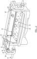
FIGURE 1 is a front perspective view of a mobile work platform assembly according to an embodiment; -
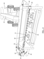
FIGURE 2 is an enlarged front perspective view of a control panel of the mobile work platform assembly ofFigure 1 ; -
FIGURE 3 is a circuit diagram of the control panel of the mobile work platform assembly ofFigure 1 ; -
FIGURE 4 is a front perspective view of mobile work platform assembly according to another embodiment; -
FIGURE 5 is an enlarged front perspective view of a connector assembly of the mobile work platform assembly ofFigure 4 ; -
FIGURE 6 is an enlarged side perspective view of the connector assembly ofFigure 5 ; and -
FIGURE 7 is an enlarged front perspective view of another connector assembly of the mobile work platform assembly ofFigure 4 . - As required, detailed embodiments of the present invention are disclosed herein; however, it is to be understood that the disclosed embodiments are merely exemplary of the invention that may be embodied in various and alternative forms. The figures are not necessarily to scale; some features may be exaggerated or minimized to show details of particular components. Therefore, specific structural and functional details disclosed herein are not to be interpreted as limiting, but merely as a representative basis for teaching one skilled in the art to variously employ the present invention.
-
Figure 1 illustrates a mobile work platform assembly referenced generally by numeral 10. The mobile work platform assembly 10 is adapted to be mounted to a land vehicle, such as an aerial lift, as is known in the art, and will be described further in a subsequent embodiment. The mobile work platform assembly 10 includes aplatform 12 sized to receive an operator upon theplatform 12. Aframe assembly 14 is provided upon theplatform 12. Theframe assembly 14 provides a frame of guard rails that extend around a perimeter of theplatform 12 to contain an operator within theframe assembly 14. Adoor 16 is provided upon theframe assembly 14 to permit operator ingress to, and egress from, theframe assembly 14. - Referring now to
Figures 1 and2 , acontrol panel assembly 18 is provided upon the mobile work platform assembly 10. Thecontrol panel assembly 18 includeshand controls 20 and afoot switch 22. Thefoot switch 22 is labeled FS in the circuit diagram ofFigure 3 . Referring back toFigures 1 and2 , thecontrol panel assembly 18 is in communication with the associated land vehicle to control movement of the vehicle and the work platform assembly 10 relative to an underlying support surface. For example, thecontrol panel assembly 18 may control transportation of the land vehicle upon the underlying support surface. Thecontrol panel assembly 18 may also control a lift mechanism for adjusting an elevation of the work platform assembly 10. Thecontrol panel assembly 18 permits the operator to move the work platform assembly 10 adjacent to an otherwise unreachable work region. The work platform assembly 10 provides aremote platform 12 for the operator to conduct work upon the associated work region. - The work platform assembly 10 includes a caution or
safety device 24 to minimize involuntary operation of thecontrol panel assembly 18, referred to as anoperator protection system 24. During a work operation, an operator may inadvertently contact thecontrol panel assembly 18. Thesafety device 24 minimizes involuntary operation of thecontrol panel assembly 18 to minimize involuntary operation of the land vehicle and lift so that actuation of thesafety device 24 disrupts control of the land vehicle and the lift. - Additionally, an operator may operate the
control panel assembly 18 to move the work platform assembly 10 while overlooking or unaware of an obstacle. Theoperator protection system 24 protects the operator from being trapped between an external structure and thecontrol panel assembly 18 by stopping the movement of the work platform assembly 10 once thecaution device 24 is activated. Thisoperator protection system 24 is a robust system that is unobtrusive, does not block the operator's view of thecontrol panel assembly 18, and provides additional workspace upon theplatform 12, once theoperator protection system 24 is initiated. - The
operator protection system 24 includes a pair ofbrackets frame assembly 14 into a workspace within the perimeter of theframe assembly 14. Theoperator protection system 24 includes atrigger cable 30 with a proximal end 32 (Figure 1 ) that is connected to theright bracket 28. With reference now toFigure 2 , amagnet 34 is connected to a distal end of thecable 30. Themagnet 34 affixes within areceptacle 36 on theleft bracket 26. An inductive orproximity sensor 38 is provided in thereceptacle 36 adjacent to the mounting surface of themagnet 34 to detect the presence of themagnet 34. Although, the pair ofbrackets frame 14, thetrigger cable 30 may be connected to any support structure on the work platform assembly 10. - The
cable 30 is attached at the distal end with themagnet 34 to a ferrous connection in thereceptacle 36 of theleft bracket 26. Theproximal end 32 is attached to theright bracket 28 and pretensioned slightly so as to give some movement to thecable 30, yet dislodge themagnet 34 from thereceptacle 36 once additional tension is applied to thecable 30. Referring now toFigures 1-3 , the position of themagnet 34 is detected by theproximity switch 38, which is labeled LS for limit switch in the circuit diagram ofFigure 3 . The limit switch LS, 38 is monitored by a processor or electronic control unit (ECU) inFigure 3 . When thetrigger cable 30 is pushed upon, thecable 30 translates themagnet 34 away from a ferrous attachment in thereceptacle 36. Removal of themagnet 34 activates theproximity switch 38. - In response to the activation of the
proximity switch 38, the ECU initiates a caution or safety mode. In the caution mode, the ECU terminates movement of the work platform assembly 10 by stopping all motion of the land vehicle and the lift. The ECU also initiates an audio and visual alarm by initiating a horn (Figure 3 ) and strobe light emitting diodes (LEDs) (alsoFigure 3 ). - The prior art has offered machine controls that are mounted on a pivoting or movable mount that trips a switch once displaced from normal operating position. This prior art system requires the operator to be pressed into the controls to stop movement of the machine. This prior art system does not allow any additional space for the operator after the switch has been tripped. This prior art system may also create opportunities for the pivot / movable mount to become contaminated by debris or corrosion causing malfunctions and requiring maintenance and repair.
- The prior art has also offered a pressure sensitive bar or switch mounted in front of the control panel. This prior art system requires the operator to be pressed into the pressure bar to stop movement of the machine. This prior art system does not provide additional space for the operator after the switch is tripped. The pressure sensitive bar is also within the workspace and may be accidentally tripped thereby creating nuisance mobility stoppages.
- The prior art has also offered a pressure sensitive bar or switch mounted a distance above a leading edge of the controls on a breakaway mount. This prior art system requires the operator to be pressed into the pressure bar to stop movement of the machine. Due to the nature of the breakaway system, this prior art system is vulnerable to breakage in a construction environment. In addition, this prior art system creates an obstruction when viewing the operator controls.
- Some prior art systems require an operator to replace parts that require tools for the replacement, in order to reset the system.
- The
operator protection system 24 provides simplicity over the prior art by providing a device that utilizes no moving switch contacts and allows theproximity switch 38 to be concealed in a protected location within thereceptacle 36. Theoperator protector system 24 also provides enhanced visibility over the prior art. By utilizing thecable 30 to actuate theswitch 38, visual obstructions of thecontrol panel assembly 18 are minimized. Due to the visibility improvement, theoperator protection system 24 allows theswitch 38 to be located in an optimal position for actuation when needed, and creates additional workspace for the operator between thecable 30 and thecontrol panel assembly 18 once thecable 30 has been disconnected from thereceptacle 36. Although thecable 30 is illustrated and described, any suitable flexible member is contemplated, such as a chain, rope, or the like. Although onemagnet 34 andsensor 38 is illustrated and described, any number of magnet connections with sensors may be employed. Theoperator protection system 24 is easily resettable, without requiring tools or replacement parts. For example, when the operator trips theprotection system 24, but is not in danger, the operator can simply grab ahold of themagnet 34 and reinsert it into thereceptacle 36, and the mobile work platform assembly 10 returns to normal operation. -
Figure 4 illustrates aland vehicle 50 according to an embodiment. Theland vehicle 50 includes alift arm 52, which supports a mobilework platform assembly 54 according to another embodiment. The mobilework platform assembly 54 is illustrated inFigures 4-7 . The mobilework platform assembly 54 includes a platform 56 (Figure 6 ), aframe assembly 58, and acontrol panel assembly 60. - A pair of
brackets frame assembly 58. Anoperator protection system 66 is mounted to the pair ofbrackets Figures 4-6 asocket 68 is supported upon theright bracket 64. Referring specifically toFigure 6 , thesocket 68 includes abore 70 and a pair or spring-loadedball bearings 72. Referring again toFigures 4-6 , theoperator protection system 66 includes acable 74. A distal end of thecable 74 is provided with a threadedstud 76 for connection to aplug 78. Theplug 78 is sized to be received in thesocket 68. Agroove 80 is formed in theplug 78 to receive theball bearings 72 to retain theplug 78 in thesocket 68. According to one embodiment, a limit switch is provided in thesocket 68 to detect the presence of theplug 78. - Referring now to
Figures 4 and7 , alimit switch 82 is provided on theleft bracket 62. A proximal end of thecable 74 is connected to thelimit switch 82. Thecable 74 is tensioned so that the limit switch is freely maintained in a neutral position. At the neutral position, thecontrol panel assembly 60 permits operation of theland vehicle 50 andlift arm 52. The tension of thecable 74 can be adjusted by the position of theplug 78 upon the threadedstud 76. If thecable 74 is pushed or pulled, thelimit switch 82 is actuated, thereby informing thecontrol panel assembly 60 of a caution event, whereby thecontrol panel assembly 60 discontinues operation of theland vehicle 50 andlift arm 52 while providing a light and sound alarm. If the displacement of thecable 74 is more than a stroke of thelimit switch 82, theplug 78 is removed from thesocket 68, thereby dropping thecable 74 and providing additional workspace for the operator. Theplug 78 andcable 74 have sufficient weight to keep theswitch 82 in the caution position until reinstalled into thesocket 68. Although oneplug 78 andsocket 68 connection is illustrated and described, both ends of thecable 74 may be connected withplug 78 andsocket 68 connections, with limit switches in one or bothsockets 68. Although acable 74 is illustrated and described, any barrier member for manual disconnection from theframe assembly 58 may be employed. Theoperator protection system 66 is easily resettable, without requiring tools or replacement parts. For example, when the operator trips theprotection system 66, but is not in danger, the operator can simply grab ahold of theplug 78 and reinsert it into thesocket 70, and the mobile work platform assembly 10 returns to normal operation. - While various embodiments are described above, it is not intended that these embodiments describe all possible forms of the invention as claimed. Rather, the words used in the specification are words of description rather than limitation, and it is understood that various changes may be made without departing from the scope of the invention as claimed. Additionally, the features of various implementing embodiments may be combined to form further embodiments of the invention as claimed.
Claims (12)
- A mobile work platform assembly (10) comprising:a platform (12) adapted to be mounted to a vehicle (50), sized to receive an operator thereupon;a control panel (18) supported upon the platform (12);a caution switch supported upon the platform (12) in electrical communication with the control panel (18) to provide a caution signal to the control panel (18) indicative of a caution event;a flexible member (30) connected to the caution switch to extend across the control panel (18) and spaced apart from the control panel (18) so that a predetermined force upon the flexible member (30) actuates the caution switch;wherein the platform (12) provides an operator workspace; andwherein a manual force upon the flexible member (30) expands the operator workspace;characterized in that the mobile work platform assembly (10) further comprises a magnet (34) connected to one of an end of the flexible member (30) and the platform (12) to attach the flexible member (30) to the platform (12).
- The mobile work platform assembly (10) of claim 1 wherein the caution switch cooperates with the magnet (34) to detect a presence and removal of the magnet (34) from the platform (12).
- The mobile work platform assembly (10) of claim 1 wherein the magnet (34) is connected to the end of the flexible member (30), and the platform (12) is formed from a ferrous material to attach the magnet (34) to the platform (12).
- The mobile work platform assembly (10) of claim 3 wherein a receptacle is formed into the platform (12), sized to receive the magnet (34).
- The mobile work platform assembly (10) of claim 4 wherein the caution switch comprises an inductive sensor oriented in the receptacle adjacent to a mounting surface of the magnet (34) to detect a presence and removal of the magnet (34).
- The mobile work platform assembly (10) of claim 1 wherein the caution switch comprises a limit switch connected to a first end of the flexible member (30) and the platform (12).
- The mobile work platform assembly (10) of claim 1 wherein the flexible member (30) comprises a cable to minimize visual obstruction of the control panel (18).
- The mobile work platform assembly (10) of claim 7 wherein the cable is pretensioned to permit limited flexibility of the cable upon receipt of a force that is less than the predetermined force.
- The mobile work platform assembly (10) of claim 1 further comprising an alarm supported upon the platform (12) in electrical communication with the control panel (18), wherein the control panel (18) is programmed to initiate the alarm in response to receipt of the caution event signal.
- The mobile work platform assembly (10) of claim 1 further comprising:. a frame assembly (14) provided upon the platform (12), the frame assembly (14) providing a frame of guard rails that extend around a perimeter of the platform (12) ; and. a pair of right and left brackets (26, 28) extending from the frame assembly (14) into the operator workspace within a perimeter of the frame assembly (14)10, wherein the flexible member (30) includes a trigger cable (30) with a proximal end (32) that is connected to the right bracket (28), the magnet (34) being connected to a distal end of the trigger cable (30) and affixes within a receptacle (36) on the left bracket (26), an inductive or proximity sensor (38) being provided in the receptacle (36) adjacent to a mounting surface of the magnet (34) to detect the presence of the magnet (34).
- A land vehicle assembly comprising:a land vehicle (50);a mobile work platform assembly (10) according to claim 1;wherein the land vehicle (50) supports the platform (12) and is in electrical communication with the control panel (18),wherein the control panel (18) is programmed to:control at least one mobile operation of the land vehicle (50), anddiscontinue the at least one mobile operation of the land vehicle (50) in response to receipt of the caution event signal.
- A method for selecting a caution mode of a mobile work platform (12), the method comprising:. providing a mobile work platform assembly (10) according to claim 1;. extending the flexible member (30) across the control panel (18);. connecting the flexible member (30) to the caution switch;the method being characterized by connecting an end of the flexible member (30) to the platform (12) with a magnet (34) so that a predetermined force upon the flexible member (30) actuates the caution switch ; andby discontinuing a mobile function of the mobile work platform (12) in response to receipt of a caution signal from the caution switch.
Priority Applications (1)
| Application Number | Priority Date | Filing Date | Title |
|---|---|---|---|
| EP23167479.7A EP4234473B1 (en) | 2016-11-14 | 2017-11-14 | SAFETY EQUIPMENT FOR MOBILE WORK PLATFORMS |
Applications Claiming Priority (3)
| Application Number | Priority Date | Filing Date | Title |
|---|---|---|---|
| US201662421537P | 2016-11-14 | 2016-11-14 | |
| US15/808,257 US10549975B2 (en) | 2016-11-14 | 2017-11-09 | Safety device for mobile work platforms |
| PCT/US2017/061440 WO2018089965A1 (en) | 2016-11-14 | 2017-11-14 | Safety device for mobile work platforms |
Related Child Applications (2)
| Application Number | Title | Priority Date | Filing Date |
|---|---|---|---|
| EP23167479.7A Division EP4234473B1 (en) | 2016-11-14 | 2017-11-14 | SAFETY EQUIPMENT FOR MOBILE WORK PLATFORMS |
| EP23167479.7A Division-Into EP4234473B1 (en) | 2016-11-14 | 2017-11-14 | SAFETY EQUIPMENT FOR MOBILE WORK PLATFORMS |
Publications (3)
| Publication Number | Publication Date |
|---|---|
| EP3538471A1 EP3538471A1 (en) | 2019-09-18 |
| EP3538471A4 EP3538471A4 (en) | 2020-07-01 |
| EP3538471B1 true EP3538471B1 (en) | 2023-06-14 |
Family
ID=62107207
Family Applications (2)
| Application Number | Title | Priority Date | Filing Date |
|---|---|---|---|
| EP17868779.4A Active EP3538471B1 (en) | 2016-11-14 | 2017-11-14 | Mobile work platform, land vehicle comprising such mobile work platform and method of using such mobile work platform |
| EP23167479.7A Active EP4234473B1 (en) | 2016-11-14 | 2017-11-14 | SAFETY EQUIPMENT FOR MOBILE WORK PLATFORMS |
Family Applications After (1)
| Application Number | Title | Priority Date | Filing Date |
|---|---|---|---|
| EP23167479.7A Active EP4234473B1 (en) | 2016-11-14 | 2017-11-14 | SAFETY EQUIPMENT FOR MOBILE WORK PLATFORMS |
Country Status (6)
| Country | Link |
|---|---|
| US (4) | US10549975B2 (en) |
| EP (2) | EP3538471B1 (en) |
| CN (3) | CN113387305B (en) |
| AU (2) | AU2017357105B2 (en) |
| CA (1) | CA3043330A1 (en) |
| WO (1) | WO2018089965A1 (en) |
Families Citing this family (10)
| Publication number | Priority date | Publication date | Assignee | Title |
|---|---|---|---|---|
| US11383963B2 (en) | 2017-03-03 | 2022-07-12 | Jlg Industries, Inc. | Obstacle detection system for an aerial work platform |
| CN106744557B (en) * | 2017-03-17 | 2023-02-28 | 浙江鼎力机械股份有限公司 | Aerial work platform with electronic induction safety protection device |
| CN109827063A (en) * | 2019-03-28 | 2019-05-31 | 湖南运想重工有限公司 | A detachable pull-rope safety protection device and an aerial work platform |
| CN110562886B (en) * | 2019-09-16 | 2024-05-31 | 浙江鼎力机械股份有限公司 | Anti-extrusion device and aerial work platform |
| FR3100805B1 (en) * | 2019-09-17 | 2021-08-13 | Manitou Bf | Platform, in particular lifting platform |
| WO2021062952A1 (en) | 2019-09-30 | 2021-04-08 | 湖南中联重科智能高空作业机械有限公司 | Anti-extrusion device for movable operating platform, push-rod-type anti-extrusion device, and high-altitude operation machine |
| US11691859B2 (en) * | 2021-01-21 | 2023-07-04 | Oshkosh Corporation | Lift device with user contact sensor |
| WO2022159601A1 (en) * | 2021-01-21 | 2022-07-28 | Oshkosh Corporation | Lift device with user contact sensor |
| CN114314465A (en) * | 2021-12-30 | 2022-04-12 | 湖南星邦智能装备股份有限公司 | An early warning system for preventing people from trapping in a work bar |
| CN114920184B (en) * | 2022-06-10 | 2022-11-25 | 湖北脉辉金茂机械有限公司 | Aerial working platform based on vertical location of cable |
Family Cites Families (39)
| Publication number | Priority date | Publication date | Assignee | Title |
|---|---|---|---|---|
| US2654869A (en) | 1950-04-17 | 1953-10-06 | Jr Ralph L Mudd | Electric swivel plug |
| US3171183A (en) * | 1961-06-20 | 1965-03-02 | James R Johnston | Utility fastener |
| US3090948A (en) * | 1961-10-31 | 1963-05-21 | Norman C Cremer | Receptacle plug to protect appliance theft |
| US3396814A (en) * | 1966-06-13 | 1968-08-13 | Edward V. Garnett | Power ladder and safety device for workman's basket |
| US3521216A (en) | 1968-06-19 | 1970-07-21 | Manuel Jerair Tolegian | Magnetic plug and socket assembly |
| US3921530A (en) | 1971-05-05 | 1975-11-25 | Us Navy | Electrical trip wire switch |
| GB1519357A (en) * | 1976-11-11 | 1978-07-26 | Dzus Fastener Europe | Fasteners |
| US4205619A (en) * | 1978-08-28 | 1980-06-03 | Mock George W Jr | Automatic flare signal apparatus |
| USRE31400E (en) * | 1979-02-21 | 1983-10-04 | Mark Industries | Self propelled and extensible boom |
| US4554420A (en) | 1984-05-01 | 1985-11-19 | Westinghouse Electric Corp. | Electrical switch |
| CN1016119B (en) * | 1985-04-01 | 1992-04-01 | 西屋电器公司 | Electrical switch |
| US4947009A (en) * | 1987-10-28 | 1990-08-07 | Mcgill Manufacturing Company, Inc. | Conscious effort safety switch |
| US5255714A (en) * | 1992-11-13 | 1993-10-26 | Perfecting Services, Inc. | Quick-action fluid coupling |
| US5622237A (en) * | 1995-10-30 | 1997-04-22 | Rollgliss, Inc. | Portable hoist system |
| US6269606B1 (en) * | 1999-05-21 | 2001-08-07 | Mccown Samps H. | Assembly and method for straightening a ground retaining wall |
| US7887104B1 (en) * | 2004-08-16 | 2011-02-15 | Hollis Wilson | Quick connect and disconnect coupler |
| US8262098B2 (en) * | 2008-02-05 | 2012-09-11 | Robert Bosch Gmbh | Rotary tool system with centering member |
| GB2457908A (en) * | 2008-02-28 | 2009-09-02 | Blue Sky Access Ltd | A safety device for an aerial lift |
| CN201236131Y (en) * | 2008-05-23 | 2009-05-13 | 杭州爱知工程车辆有限公司 | Intelligent control system of high-altitude operation car and high-altitude operation car thereof |
| GB2472441B (en) * | 2009-08-07 | 2013-02-13 | Niftylift Ltd | Control system,preferably for enhanced operator safety |
| GB201011136D0 (en) * | 2010-07-02 | 2010-08-18 | Blue Sky Access Ltd | An aerial lift with safety device |
| US10124999B2 (en) * | 2010-12-20 | 2018-11-13 | Jlg Industries, Inc. | Opto-electric system of enhanced operator control station protection |
| JP5727622B2 (en) | 2010-12-20 | 2015-06-03 | ジェイエルジー インダストリーズ インク.Jlg Industries Inc. | Work platform with protection against persistent involuntary operations (negligible operations) |
| US10029899B2 (en) * | 2010-12-20 | 2018-07-24 | Jlg Industries, Inc. | Work platform with protection against sustained involuntary operation |
| WO2012109444A2 (en) * | 2011-02-09 | 2012-08-16 | Baillargeon Paul D | Warning and message delivery and logging system utilizable in the monitoring of fall arresting and prevention devices and method of same |
| US20120294672A1 (en) * | 2011-05-17 | 2012-11-22 | Real Hicks Properties, Llc | Tripod Adapter for Shooting Rests and Other Accessories |
| US9597475B2 (en) * | 2011-07-15 | 2017-03-21 | Jack C McPhearson | Fast connect device for oxygen humidity bottles and other medical containers |
| US9010355B1 (en) * | 2011-10-11 | 2015-04-21 | Bert J. Achez | Easy-flow flushing system |
| US8665106B2 (en) * | 2011-12-13 | 2014-03-04 | Lina HEIDVALL | Personal audio cable alarm device |
| GB2497803B (en) | 2011-12-21 | 2014-12-03 | Bluesky Solutions Ltd | Aerial lift with safety device and alarm |
| US9089723B2 (en) * | 2012-02-06 | 2015-07-28 | Sapheco, LLC | Safety Protection apparatus for personnel on oil drilling derricks |
| EP2789262B1 (en) * | 2013-04-12 | 2018-06-13 | Logicdata Electronic&Software Entwicklungs GmbH | Adjustable seating furniture with hand-switch arrangement and assembly method for an adjustable seating furniture |
| FR3007401B1 (en) * | 2013-06-25 | 2015-07-03 | Haulotte Group | LIFT BOOM WITH SAFE CONTROL UNIT |
| DE102014118066A1 (en) * | 2014-12-08 | 2016-06-09 | Endress + Hauser Conducta Gesellschaft für Mess- und Regeltechnik mbH + Co. KG | Method and connector for informing a process control center about disconnecting a sensor from a transmitter |
| US10099909B2 (en) * | 2015-05-15 | 2018-10-16 | Quanta Associates, L.P. | Aerialift safety device and fall restraint |
| US20180207667A1 (en) * | 2015-09-02 | 2018-07-26 | Rohm And Haas Company | Water cleanout tool and method for foam gun dispenser |
| WO2021041708A1 (en) * | 2019-08-28 | 2021-03-04 | Oshkosh Corporation | Fall arrest system |
| WO2022159601A1 (en) * | 2021-01-21 | 2022-07-28 | Oshkosh Corporation | Lift device with user contact sensor |
| US11691859B2 (en) * | 2021-01-21 | 2023-07-04 | Oshkosh Corporation | Lift device with user contact sensor |
-
2017
- 2017-11-09 US US15/808,257 patent/US10549975B2/en active Active
- 2017-11-14 CN CN202110661572.4A patent/CN113387305B/en active Active
- 2017-11-14 CA CA3043330A patent/CA3043330A1/en active Pending
- 2017-11-14 EP EP17868779.4A patent/EP3538471B1/en active Active
- 2017-11-14 AU AU2017357105A patent/AU2017357105B2/en active Active
- 2017-11-14 CN CN202311788160.2A patent/CN117602552A/en active Pending
- 2017-11-14 WO PCT/US2017/061440 patent/WO2018089965A1/en not_active Ceased
- 2017-11-14 EP EP23167479.7A patent/EP4234473B1/en active Active
- 2017-11-14 CN CN201780070396.9A patent/CN109952266B/en not_active Ceased
-
2019
- 2019-12-20 US US16/723,432 patent/US11161726B2/en active Active
-
2021
- 2021-10-15 US US17/502,541 patent/US20220033237A1/en active Pending
-
2023
- 2023-08-10 AU AU2023214303A patent/AU2023214303B2/en active Active
-
2024
- 2024-10-21 US US18/921,330 patent/US20250042707A1/en active Pending
Also Published As
| Publication number | Publication date |
|---|---|
| CN113387305A (en) | 2021-09-14 |
| EP4234473A2 (en) | 2023-08-30 |
| WO2018089965A1 (en) | 2018-05-17 |
| AU2017357105A1 (en) | 2019-05-30 |
| EP3538471A4 (en) | 2020-07-01 |
| US11161726B2 (en) | 2021-11-02 |
| US10549975B2 (en) | 2020-02-04 |
| CN117602552A (en) | 2024-02-27 |
| US20180134534A1 (en) | 2018-05-17 |
| CN113387305B (en) | 2024-01-09 |
| CN109952266A (en) | 2019-06-28 |
| AU2023214303B2 (en) | 2025-06-05 |
| EP4234473B1 (en) | 2026-05-20 |
| CA3043330A1 (en) | 2018-05-17 |
| US20250042707A1 (en) | 2025-02-06 |
| BR112019009613A2 (en) | 2019-08-13 |
| CN109952266B (en) | 2021-06-15 |
| EP4234473A3 (en) | 2023-10-11 |
| AU2017357105B2 (en) | 2023-05-11 |
| US20200122990A1 (en) | 2020-04-23 |
| EP3538471A1 (en) | 2019-09-18 |
| AU2023214303A1 (en) | 2023-08-31 |
| US20220033237A1 (en) | 2022-02-03 |
Similar Documents
| Publication | Publication Date | Title |
|---|---|---|
| AU2023214303B2 (en) | Safety device for mobile work platforms | |
| US12428279B2 (en) | Anti-entrapment device for scissor lifts | |
| EP2588402B1 (en) | An aerial lift with safety device | |
| KR101511900B1 (en) | Wireless safety tripod for vehicle | |
| GB2481709A (en) | Load sensitive safety device for an aerial lift | |
| US6104305A (en) | Pole alarm system | |
| US10340095B2 (en) | Safety-switch device for use on a movable device | |
| EP3260172A1 (en) | Security gear adapted to be worn by an operator to be secured from falling off an aerial work platform | |
| WO2008102225A3 (en) | Device for sensing electric hazards | |
| CN210620166U (en) | Anti-extrusion device and aerial work platform | |
| KR101193372B1 (en) | The safety stick for the heavy vehicles | |
| US20230030999A1 (en) | Construction Vehicle Safety Mechanism | |
| BR112019009613B1 (en) | MOBILE WORK PLATFORM ASSEMBLY AND GROUND VEHICLE ASSEMBLY | |
| JP3353111B2 (en) | Pole-shaped alarm device | |
| ITFO20080023A1 (en) | DEVICE FOR VERIFICATION OF THE VISUAL FIELD AVAILABLE TO THE LEADERS OF INDUSTRIAL MACHINES, AGRICULTURAL AND EARTH MOVEMENT |
Legal Events
| Date | Code | Title | Description |
|---|---|---|---|
| STAA | Information on the status of an ep patent application or granted ep patent |
Free format text: STATUS: THE INTERNATIONAL PUBLICATION HAS BEEN MADE |
|
| PUAI | Public reference made under article 153(3) epc to a published international application that has entered the european phase |
Free format text: ORIGINAL CODE: 0009012 |
|
| STAA | Information on the status of an ep patent application or granted ep patent |
Free format text: STATUS: REQUEST FOR EXAMINATION WAS MADE |
|
| 17P | Request for examination filed |
Effective date: 20190514 |
|
| AK | Designated contracting states |
Kind code of ref document: A1 Designated state(s): AL AT BE BG CH CY CZ DE DK EE ES FI FR GB GR HR HU IE IS IT LI LT LU LV MC MK MT NL NO PL PT RO RS SE SI SK SM TR |
|
| AX | Request for extension of the european patent |
Extension state: BA ME |
|
| DAV | Request for validation of the european patent (deleted) | ||
| DAX | Request for extension of the european patent (deleted) | ||
| A4 | Supplementary search report drawn up and despatched |
Effective date: 20200603 |
|
| RIC1 | Information provided on ipc code assigned before grant |
Ipc: G08B 21/02 20060101ALI20200527BHEP Ipc: B66F 11/04 20060101ALI20200527BHEP Ipc: B66F 17/00 20060101ALI20200527BHEP Ipc: B66C 15/06 20060101AFI20200527BHEP |
|
| GRAP | Despatch of communication of intention to grant a patent |
Free format text: ORIGINAL CODE: EPIDOSNIGR1 |
|
| STAA | Information on the status of an ep patent application or granted ep patent |
Free format text: STATUS: GRANT OF PATENT IS INTENDED |
|
| INTG | Intention to grant announced |
Effective date: 20230303 |
|
| GRAS | Grant fee paid |
Free format text: ORIGINAL CODE: EPIDOSNIGR3 |
|
| GRAA | (expected) grant |
Free format text: ORIGINAL CODE: 0009210 |
|
| STAA | Information on the status of an ep patent application or granted ep patent |
Free format text: STATUS: THE PATENT HAS BEEN GRANTED |
|
| AK | Designated contracting states |
Kind code of ref document: B1 Designated state(s): AL AT BE BG CH CY CZ DE DK EE ES FI FR GB GR HR HU IE IS IT LI LT LU LV MC MK MT NL NO PL PT RO RS SE SI SK SM TR |
|
| REG | Reference to a national code |
Ref country code: CH Ref legal event code: EP |
|
| REG | Reference to a national code |
Ref country code: DE Ref legal event code: R096 Ref document number: 602017070307 Country of ref document: DE |
|
| P01 | Opt-out of the competence of the unified patent court (upc) registered |
Effective date: 20230530 |
|
| REG | Reference to a national code |
Ref country code: AT Ref legal event code: REF Ref document number: 1579124 Country of ref document: AT Kind code of ref document: T Effective date: 20230715 |
|
| REG | Reference to a national code |
Ref country code: NL Ref legal event code: FP |
|
| REG | Reference to a national code |
Ref country code: LT Ref legal event code: MG9D |
|
| PG25 | Lapsed in a contracting state [announced via postgrant information from national office to epo] |
Ref country code: SE Free format text: LAPSE BECAUSE OF FAILURE TO SUBMIT A TRANSLATION OF THE DESCRIPTION OR TO PAY THE FEE WITHIN THE PRESCRIBED TIME-LIMIT Effective date: 20230614 Ref country code: NO Free format text: LAPSE BECAUSE OF FAILURE TO SUBMIT A TRANSLATION OF THE DESCRIPTION OR TO PAY THE FEE WITHIN THE PRESCRIBED TIME-LIMIT Effective date: 20230914 Ref country code: ES Free format text: LAPSE BECAUSE OF FAILURE TO SUBMIT A TRANSLATION OF THE DESCRIPTION OR TO PAY THE FEE WITHIN THE PRESCRIBED TIME-LIMIT Effective date: 20230614 |
|
| REG | Reference to a national code |
Ref country code: AT Ref legal event code: MK05 Ref document number: 1579124 Country of ref document: AT Kind code of ref document: T Effective date: 20230614 |
|
| PG25 | Lapsed in a contracting state [announced via postgrant information from national office to epo] |
Ref country code: RS Free format text: LAPSE BECAUSE OF FAILURE TO SUBMIT A TRANSLATION OF THE DESCRIPTION OR TO PAY THE FEE WITHIN THE PRESCRIBED TIME-LIMIT Effective date: 20230614 Ref country code: LV Free format text: LAPSE BECAUSE OF FAILURE TO SUBMIT A TRANSLATION OF THE DESCRIPTION OR TO PAY THE FEE WITHIN THE PRESCRIBED TIME-LIMIT Effective date: 20230614 Ref country code: LT Free format text: LAPSE BECAUSE OF FAILURE TO SUBMIT A TRANSLATION OF THE DESCRIPTION OR TO PAY THE FEE WITHIN THE PRESCRIBED TIME-LIMIT Effective date: 20230614 Ref country code: HR Free format text: LAPSE BECAUSE OF FAILURE TO SUBMIT A TRANSLATION OF THE DESCRIPTION OR TO PAY THE FEE WITHIN THE PRESCRIBED TIME-LIMIT Effective date: 20230614 Ref country code: GR Free format text: LAPSE BECAUSE OF FAILURE TO SUBMIT A TRANSLATION OF THE DESCRIPTION OR TO PAY THE FEE WITHIN THE PRESCRIBED TIME-LIMIT Effective date: 20230915 |
|
| PG25 | Lapsed in a contracting state [announced via postgrant information from national office to epo] |
Ref country code: FI Free format text: LAPSE BECAUSE OF FAILURE TO SUBMIT A TRANSLATION OF THE DESCRIPTION OR TO PAY THE FEE WITHIN THE PRESCRIBED TIME-LIMIT Effective date: 20230614 |
|
| PG25 | Lapsed in a contracting state [announced via postgrant information from national office to epo] |
Ref country code: SK Free format text: LAPSE BECAUSE OF FAILURE TO SUBMIT A TRANSLATION OF THE DESCRIPTION OR TO PAY THE FEE WITHIN THE PRESCRIBED TIME-LIMIT Effective date: 20230614 |
|
| PG25 | Lapsed in a contracting state [announced via postgrant information from national office to epo] |
Ref country code: IS Free format text: LAPSE BECAUSE OF FAILURE TO SUBMIT A TRANSLATION OF THE DESCRIPTION OR TO PAY THE FEE WITHIN THE PRESCRIBED TIME-LIMIT Effective date: 20231014 |
|
| PG25 | Lapsed in a contracting state [announced via postgrant information from national office to epo] |
Ref country code: SM Free format text: LAPSE BECAUSE OF FAILURE TO SUBMIT A TRANSLATION OF THE DESCRIPTION OR TO PAY THE FEE WITHIN THE PRESCRIBED TIME-LIMIT Effective date: 20230614 Ref country code: SK Free format text: LAPSE BECAUSE OF FAILURE TO SUBMIT A TRANSLATION OF THE DESCRIPTION OR TO PAY THE FEE WITHIN THE PRESCRIBED TIME-LIMIT Effective date: 20230614 Ref country code: RO Free format text: LAPSE BECAUSE OF FAILURE TO SUBMIT A TRANSLATION OF THE DESCRIPTION OR TO PAY THE FEE WITHIN THE PRESCRIBED TIME-LIMIT Effective date: 20230614 Ref country code: PT Free format text: LAPSE BECAUSE OF FAILURE TO SUBMIT A TRANSLATION OF THE DESCRIPTION OR TO PAY THE FEE WITHIN THE PRESCRIBED TIME-LIMIT Effective date: 20231016 Ref country code: IS Free format text: LAPSE BECAUSE OF FAILURE TO SUBMIT A TRANSLATION OF THE DESCRIPTION OR TO PAY THE FEE WITHIN THE PRESCRIBED TIME-LIMIT Effective date: 20231014 Ref country code: EE Free format text: LAPSE BECAUSE OF FAILURE TO SUBMIT A TRANSLATION OF THE DESCRIPTION OR TO PAY THE FEE WITHIN THE PRESCRIBED TIME-LIMIT Effective date: 20230614 Ref country code: CZ Free format text: LAPSE BECAUSE OF FAILURE TO SUBMIT A TRANSLATION OF THE DESCRIPTION OR TO PAY THE FEE WITHIN THE PRESCRIBED TIME-LIMIT Effective date: 20230614 Ref country code: AT Free format text: LAPSE BECAUSE OF FAILURE TO SUBMIT A TRANSLATION OF THE DESCRIPTION OR TO PAY THE FEE WITHIN THE PRESCRIBED TIME-LIMIT Effective date: 20230614 |
|
| PG25 | Lapsed in a contracting state [announced via postgrant information from national office to epo] |
Ref country code: PL Free format text: LAPSE BECAUSE OF FAILURE TO SUBMIT A TRANSLATION OF THE DESCRIPTION OR TO PAY THE FEE WITHIN THE PRESCRIBED TIME-LIMIT Effective date: 20230614 |
|
| REG | Reference to a national code |
Ref country code: DE Ref legal event code: R097 Ref document number: 602017070307 Country of ref document: DE |
|
| PLBE | No opposition filed within time limit |
Free format text: ORIGINAL CODE: 0009261 |
|
| STAA | Information on the status of an ep patent application or granted ep patent |
Free format text: STATUS: NO OPPOSITION FILED WITHIN TIME LIMIT |
|
| PG25 | Lapsed in a contracting state [announced via postgrant information from national office to epo] |
Ref country code: DK Free format text: LAPSE BECAUSE OF FAILURE TO SUBMIT A TRANSLATION OF THE DESCRIPTION OR TO PAY THE FEE WITHIN THE PRESCRIBED TIME-LIMIT Effective date: 20230614 |
|
| PG25 | Lapsed in a contracting state [announced via postgrant information from national office to epo] |
Ref country code: SI Free format text: LAPSE BECAUSE OF FAILURE TO SUBMIT A TRANSLATION OF THE DESCRIPTION OR TO PAY THE FEE WITHIN THE PRESCRIBED TIME-LIMIT Effective date: 20230614 |
|
| 26N | No opposition filed |
Effective date: 20240315 |
|
| PG25 | Lapsed in a contracting state [announced via postgrant information from national office to epo] |
Ref country code: SI Free format text: LAPSE BECAUSE OF FAILURE TO SUBMIT A TRANSLATION OF THE DESCRIPTION OR TO PAY THE FEE WITHIN THE PRESCRIBED TIME-LIMIT Effective date: 20230614 Ref country code: IT Free format text: LAPSE BECAUSE OF FAILURE TO SUBMIT A TRANSLATION OF THE DESCRIPTION OR TO PAY THE FEE WITHIN THE PRESCRIBED TIME-LIMIT Effective date: 20230614 |
|
| PG25 | Lapsed in a contracting state [announced via postgrant information from national office to epo] |
Ref country code: MC Free format text: LAPSE BECAUSE OF FAILURE TO SUBMIT A TRANSLATION OF THE DESCRIPTION OR TO PAY THE FEE WITHIN THE PRESCRIBED TIME-LIMIT Effective date: 20230614 |
|
| PG25 | Lapsed in a contracting state [announced via postgrant information from national office to epo] |
Ref country code: LU Free format text: LAPSE BECAUSE OF NON-PAYMENT OF DUE FEES Effective date: 20231114 |
|
| PG25 | Lapsed in a contracting state [announced via postgrant information from national office to epo] |
Ref country code: MC Free format text: LAPSE BECAUSE OF FAILURE TO SUBMIT A TRANSLATION OF THE DESCRIPTION OR TO PAY THE FEE WITHIN THE PRESCRIBED TIME-LIMIT Effective date: 20230614 Ref country code: LU Free format text: LAPSE BECAUSE OF NON-PAYMENT OF DUE FEES Effective date: 20231114 |
|
| REG | Reference to a national code |
Ref country code: BE Ref legal event code: MM Effective date: 20231130 |
|
| REG | Reference to a national code |
Ref country code: IE Ref legal event code: MM4A |
|
| PG25 | Lapsed in a contracting state [announced via postgrant information from national office to epo] |
Ref country code: IE Free format text: LAPSE BECAUSE OF NON-PAYMENT OF DUE FEES Effective date: 20231114 |
|
| PG25 | Lapsed in a contracting state [announced via postgrant information from national office to epo] |
Ref country code: BE Free format text: LAPSE BECAUSE OF NON-PAYMENT OF DUE FEES Effective date: 20231130 |
|
| PG25 | Lapsed in a contracting state [announced via postgrant information from national office to epo] |
Ref country code: IE Free format text: LAPSE BECAUSE OF NON-PAYMENT OF DUE FEES Effective date: 20231114 Ref country code: BE Free format text: LAPSE BECAUSE OF NON-PAYMENT OF DUE FEES Effective date: 20231130 |
|
| PG25 | Lapsed in a contracting state [announced via postgrant information from national office to epo] |
Ref country code: BG Free format text: LAPSE BECAUSE OF FAILURE TO SUBMIT A TRANSLATION OF THE DESCRIPTION OR TO PAY THE FEE WITHIN THE PRESCRIBED TIME-LIMIT Effective date: 20230614 |
|
| PG25 | Lapsed in a contracting state [announced via postgrant information from national office to epo] |
Ref country code: BG Free format text: LAPSE BECAUSE OF FAILURE TO SUBMIT A TRANSLATION OF THE DESCRIPTION OR TO PAY THE FEE WITHIN THE PRESCRIBED TIME-LIMIT Effective date: 20230614 |
|
| PG25 | Lapsed in a contracting state [announced via postgrant information from national office to epo] |
Ref country code: CY Free format text: LAPSE BECAUSE OF FAILURE TO SUBMIT A TRANSLATION OF THE DESCRIPTION OR TO PAY THE FEE WITHIN THE PRESCRIBED TIME-LIMIT; INVALID AB INITIO Effective date: 20171114 |
|
| PG25 | Lapsed in a contracting state [announced via postgrant information from national office to epo] |
Ref country code: HU Free format text: LAPSE BECAUSE OF FAILURE TO SUBMIT A TRANSLATION OF THE DESCRIPTION OR TO PAY THE FEE WITHIN THE PRESCRIBED TIME-LIMIT; INVALID AB INITIO Effective date: 20171114 |
|
| REG | Reference to a national code |
Ref country code: CH Ref legal event code: U11 Free format text: ST27 STATUS EVENT CODE: U-0-0-U10-U11 (AS PROVIDED BY THE NATIONAL OFFICE) Effective date: 20251201 |
|
| PG25 | Lapsed in a contracting state [announced via postgrant information from national office to epo] |
Ref country code: TR Free format text: LAPSE BECAUSE OF FAILURE TO SUBMIT A TRANSLATION OF THE DESCRIPTION OR TO PAY THE FEE WITHIN THE PRESCRIBED TIME-LIMIT Effective date: 20230614 |
|
| PGFP | Annual fee paid to national office [announced via postgrant information from national office to epo] |
Ref country code: NL Payment date: 20251119 Year of fee payment: 9 |
|
| PGFP | Annual fee paid to national office [announced via postgrant information from national office to epo] |
Ref country code: DE Payment date: 20251119 Year of fee payment: 9 |
|
| PGFP | Annual fee paid to national office [announced via postgrant information from national office to epo] |
Ref country code: GB Payment date: 20251121 Year of fee payment: 9 |
|
| PGFP | Annual fee paid to national office [announced via postgrant information from national office to epo] |
Ref country code: FR Payment date: 20251126 Year of fee payment: 9 |
|
| PGFP | Annual fee paid to national office [announced via postgrant information from national office to epo] |
Ref country code: CH Payment date: 20251201 Year of fee payment: 9 |