EP3537624A1 - Beam determination method, downlink transmission demodulation method, user equipment and base station - Google Patents
Beam determination method, downlink transmission demodulation method, user equipment and base station Download PDFInfo
- Publication number
- EP3537624A1 EP3537624A1 EP17867952.8A EP17867952A EP3537624A1 EP 3537624 A1 EP3537624 A1 EP 3537624A1 EP 17867952 A EP17867952 A EP 17867952A EP 3537624 A1 EP3537624 A1 EP 3537624A1
- Authority
- EP
- European Patent Office
- Prior art keywords
- base station
- transmission
- beams
- downlink control
- transmission beam
- Prior art date
- Legal status (The legal status is an assumption and is not a legal conclusion. Google has not performed a legal analysis and makes no representation as to the accuracy of the status listed.)
- Withdrawn
Links
Images





Classifications
-
- H—ELECTRICITY
- H04—ELECTRIC COMMUNICATION TECHNIQUE
- H04B—TRANSMISSION
- H04B7/00—Radio transmission systems, i.e. using radiation field
- H04B7/02—Diversity systems; Multi-antenna system, i.e. transmission or reception using multiple antennas
- H04B7/04—Diversity systems; Multi-antenna system, i.e. transmission or reception using multiple antennas using two or more spaced independent antennas
- H04B7/06—Diversity systems; Multi-antenna system, i.e. transmission or reception using multiple antennas using two or more spaced independent antennas at the transmitting station
- H04B7/0613—Diversity systems; Multi-antenna system, i.e. transmission or reception using multiple antennas using two or more spaced independent antennas at the transmitting station using simultaneous transmission
- H04B7/0615—Diversity systems; Multi-antenna system, i.e. transmission or reception using multiple antennas using two or more spaced independent antennas at the transmitting station using simultaneous transmission of weighted versions of same signal
- H04B7/0619—Diversity systems; Multi-antenna system, i.e. transmission or reception using multiple antennas using two or more spaced independent antennas at the transmitting station using simultaneous transmission of weighted versions of same signal using feedback from receiving side
- H04B7/0621—Feedback content
- H04B7/0626—Channel coefficients, e.g. channel state information [CSI]
-
- H—ELECTRICITY
- H04—ELECTRIC COMMUNICATION TECHNIQUE
- H04B—TRANSMISSION
- H04B7/00—Radio transmission systems, i.e. using radiation field
- H04B7/02—Diversity systems; Multi-antenna system, i.e. transmission or reception using multiple antennas
- H04B7/04—Diversity systems; Multi-antenna system, i.e. transmission or reception using multiple antennas using two or more spaced independent antennas
- H04B7/06—Diversity systems; Multi-antenna system, i.e. transmission or reception using multiple antennas using two or more spaced independent antennas at the transmitting station
-
- H—ELECTRICITY
- H04—ELECTRIC COMMUNICATION TECHNIQUE
- H04B—TRANSMISSION
- H04B7/00—Radio transmission systems, i.e. using radiation field
- H04B7/02—Diversity systems; Multi-antenna system, i.e. transmission or reception using multiple antennas
- H04B7/04—Diversity systems; Multi-antenna system, i.e. transmission or reception using multiple antennas using two or more spaced independent antennas
- H04B7/06—Diversity systems; Multi-antenna system, i.e. transmission or reception using multiple antennas using two or more spaced independent antennas at the transmitting station
- H04B7/0613—Diversity systems; Multi-antenna system, i.e. transmission or reception using multiple antennas using two or more spaced independent antennas at the transmitting station using simultaneous transmission
- H04B7/0615—Diversity systems; Multi-antenna system, i.e. transmission or reception using multiple antennas using two or more spaced independent antennas at the transmitting station using simultaneous transmission of weighted versions of same signal
- H04B7/0617—Diversity systems; Multi-antenna system, i.e. transmission or reception using multiple antennas using two or more spaced independent antennas at the transmitting station using simultaneous transmission of weighted versions of same signal for beam forming
-
- H—ELECTRICITY
- H04—ELECTRIC COMMUNICATION TECHNIQUE
- H04B—TRANSMISSION
- H04B7/00—Radio transmission systems, i.e. using radiation field
- H04B7/02—Diversity systems; Multi-antenna system, i.e. transmission or reception using multiple antennas
- H04B7/04—Diversity systems; Multi-antenna system, i.e. transmission or reception using multiple antennas using two or more spaced independent antennas
- H04B7/06—Diversity systems; Multi-antenna system, i.e. transmission or reception using multiple antennas using two or more spaced independent antennas at the transmitting station
- H04B7/0613—Diversity systems; Multi-antenna system, i.e. transmission or reception using multiple antennas using two or more spaced independent antennas at the transmitting station using simultaneous transmission
- H04B7/0615—Diversity systems; Multi-antenna system, i.e. transmission or reception using multiple antennas using two or more spaced independent antennas at the transmitting station using simultaneous transmission of weighted versions of same signal
- H04B7/0619—Diversity systems; Multi-antenna system, i.e. transmission or reception using multiple antennas using two or more spaced independent antennas at the transmitting station using simultaneous transmission of weighted versions of same signal using feedback from receiving side
- H04B7/0621—Feedback content
-
- H—ELECTRICITY
- H04—ELECTRIC COMMUNICATION TECHNIQUE
- H04B—TRANSMISSION
- H04B7/00—Radio transmission systems, i.e. using radiation field
- H04B7/02—Diversity systems; Multi-antenna system, i.e. transmission or reception using multiple antennas
- H04B7/04—Diversity systems; Multi-antenna system, i.e. transmission or reception using multiple antennas using two or more spaced independent antennas
- H04B7/06—Diversity systems; Multi-antenna system, i.e. transmission or reception using multiple antennas using two or more spaced independent antennas at the transmitting station
- H04B7/0613—Diversity systems; Multi-antenna system, i.e. transmission or reception using multiple antennas using two or more spaced independent antennas at the transmitting station using simultaneous transmission
- H04B7/0615—Diversity systems; Multi-antenna system, i.e. transmission or reception using multiple antennas using two or more spaced independent antennas at the transmitting station using simultaneous transmission of weighted versions of same signal
- H04B7/0619—Diversity systems; Multi-antenna system, i.e. transmission or reception using multiple antennas using two or more spaced independent antennas at the transmitting station using simultaneous transmission of weighted versions of same signal using feedback from receiving side
- H04B7/0621—Feedback content
- H04B7/063—Parameters other than those covered in groups H04B7/0623 - H04B7/0634, e.g. channel matrix rank or transmit mode selection
-
- H—ELECTRICITY
- H04—ELECTRIC COMMUNICATION TECHNIQUE
- H04B—TRANSMISSION
- H04B7/00—Radio transmission systems, i.e. using radiation field
- H04B7/02—Diversity systems; Multi-antenna system, i.e. transmission or reception using multiple antennas
- H04B7/04—Diversity systems; Multi-antenna system, i.e. transmission or reception using multiple antennas using two or more spaced independent antennas
- H04B7/06—Diversity systems; Multi-antenna system, i.e. transmission or reception using multiple antennas using two or more spaced independent antennas at the transmitting station
- H04B7/0686—Hybrid systems, i.e. switching and simultaneous transmission
- H04B7/0695—Hybrid systems, i.e. switching and simultaneous transmission using beam selection
- H04B7/06952—Selecting one or more beams from a plurality of beams, e.g. beam training, management or sweeping
- H04B7/06966—Selecting one or more beams from a plurality of beams, e.g. beam training, management or sweeping using beam correspondence; using channel reciprocity, e.g. downlink beam training based on uplink sounding reference signal [SRS]
-
- H—ELECTRICITY
- H04—ELECTRIC COMMUNICATION TECHNIQUE
- H04B—TRANSMISSION
- H04B7/00—Radio transmission systems, i.e. using radiation field
- H04B7/02—Diversity systems; Multi-antenna system, i.e. transmission or reception using multiple antennas
- H04B7/04—Diversity systems; Multi-antenna system, i.e. transmission or reception using multiple antennas using two or more spaced independent antennas
- H04B7/08—Diversity systems; Multi-antenna system, i.e. transmission or reception using multiple antennas using two or more spaced independent antennas at the receiving station
-
- H—ELECTRICITY
- H04—ELECTRIC COMMUNICATION TECHNIQUE
- H04B—TRANSMISSION
- H04B7/00—Radio transmission systems, i.e. using radiation field
- H04B7/02—Diversity systems; Multi-antenna system, i.e. transmission or reception using multiple antennas
- H04B7/04—Diversity systems; Multi-antenna system, i.e. transmission or reception using multiple antennas using two or more spaced independent antennas
- H04B7/08—Diversity systems; Multi-antenna system, i.e. transmission or reception using multiple antennas using two or more spaced independent antennas at the receiving station
- H04B7/0868—Hybrid systems, i.e. switching and combining
- H04B7/088—Hybrid systems, i.e. switching and combining using beam selection
Definitions
- the present disclosure relates to a field of communications, and in particular to a determination method, a downlink transmission demodulation method performed in a communication system, and corresponding user equipment and base station.
- a beam forming technique in the UE and the base station that is, both the base station and the UE may use a plurality of beams for signal transmission and reception.
- Each transmission beam of the base station and each reception beam of the UE may form one downlink beam pair, and each reception beam of the base station and each transmission beam of the UE may form one uplink beam pair.
- neither the signal transmitted through each downlink beam pair can obtain good reception quality at the UE, nor the signal transmitted through each uplink beam pair can obtain good reception quality at the base station.
- a beam determination method performed by a user equipment in a communication system including a base station and a user equipment, the base station having a plurality of transmission beams, the method comprising: transmitting, to the base station, CSI feedback for a transmission beam of the base station; determining, according to the CSI feedback for the transmission beam of the base station within a preset time window, a first transmission beam of the base station in all transmission beams of the base station having CSI feedback within the preset time window, and receiving, through a first reception beam corresponding to the first transmission beam, downlink control information transmitted by the base station through the first transmission beam.
- the transmission beam may be a CSI-RS based beam or a Synchronization Signal Block (SS block) based beam.
- SS block Synchronization Signal Block
- a beam determination method performed by a base station in a communication system including a base station and a user equipment, the base station having a plurality of transmission beams, the method comprising: receiving CSI feedback transmitted by the user equipment for the transmission beam of the base station; determining, according to the CSI feedback for the transmission beam of the base station within a preset time window, a first transmission beam of the base station in all transmission beams of the base station having CSI feedback within the preset time window, and transmitting downlink control information through the first transmission beam.
- a user equipment the user equipment being in a communication system, the communication system further including a base station, the base station having a plurality of transmission beams, wherein the user equipment comprising: a feedback unit configured to transmit CSI feedback for a transmission beam of the base station to the base station; a beam determination unit configured to determine, according to the CSI feedback for the transmission beam of the base station within a preset time window, a first transmission beam of the base station in all transmission beams of the base station having CSI feedback within the preset time window, and receiving, through a first reception beam corresponding to the first transmission beam, downlink control information transmitted by the base station through the first transmission beam.
- a base station is provided, the base station being in a communication system, the communication system further including a user equipment, the base station having a plurality of transmission beams, and the base station comprising: a reception unit configured to receive CSI feedback transmitted by the user equipment for the transmission beam of the base station; a first transmission unit configured to determine, according to the CSI feedback for the transmission beam of the base station within a preset time window, a first transmission beam of the base station in all transmission beams of the base station having CSI feedback within the preset time window, and transmitting downlink control information through the first transmission beam.
- a demodulation method for downlink transmission performed by a user equipment in a communication system including a base station and a user equipment, the base station having a plurality of transmission beams, the method comprising: determining M preferred beams in the plurality of transmission beams of the base station; receiving, through one or more reception beams corresponding to any one or more of N preferred beams in the M preferred beams, downlink control information transmitted by the base station, wherein N ⁇ M, the base station transmitting signaling including same downlink control information through the N preferred beams during the transmission time period of the downlink control information.
- a demodulation method for downlink transmission performed by a base station in a communication system including a base station and a user equipment, the base station having a plurality of transmission beams, the method comprising: determining M preferred beams in the plurality of transmission beams of the base station; transmitting signaling including same downlink control information through N preferred beams in the M preferred beams, where N ⁇ M.
- a user equipment the user equipment being in a communication system, the communication system further including a base station, the base station having a plurality of transmission beams, wherein the user equipment comprising: a first preference selection unit, configured to determine M preferred beams in the plurality of transmission beams of the base station; an information reception unit configured to receive, through one or more reception beams corresponding to any one or more of N preferred beams in the M preferred beams, downlink control information transmitted by the base station, wherein N ⁇ M, the base station transmitting signaling including same downlink control information through the N preferred beams during the transmission time period of the downlink control information.
- a first preference selection unit configured to determine M preferred beams in the plurality of transmission beams of the base station
- an information reception unit configured to receive, through one or more reception beams corresponding to any one or more of N preferred beams in the M preferred beams, downlink control information transmitted by the base station, wherein N ⁇ M, the base station transmitting signaling including same downlink control information through the N preferred beams during
- a base station the base station being in a communication system, the communication system further including a user equipment, the base station having a plurality of transmission beams, wherein the base station comprising: a second preference selection unit configured to determine M preferred beams in the plurality of transmission beams of the base station; a second transmission unit configured to transmit signaling including same downlink control information through N preferred beams in the M preferred beams, where N ⁇ M.
- a demodulation method for downlink transmission performed by a user equipment in a communication system including a base station and a user equipment, the base station having a plurality of transmission beams, the method comprising: determining relations between blind decoding candidate resource blocks in a search space configuration and the transmission beams of the base station, the blind decoding candidate resource blocks including one or more time-frequency elements; determining the transmission beam of the base station on the blind decoding candidate resource blocks according to the relations, and receiving downlink control information transmitted by the base station using reception beams corresponding to the transmission beams of the base station, to obtain resource blocks corresponding to the downlink control information and a corresponding second transmission beam.
- a demodulation method for downlink transmission performed by a base station in a communication system including a base station and a user equipment, the base station having a plurality of transmission beams, the method comprising: determining relations between blind decoding PDCCH candidate resource blocks in a search space configuration and the transmission beams of the base station, the blind decoding PDCCH candidate resource blocks including one or more time-frequency elements; determining a second transmission beam for transmitting downlink control information, and transmitting the downlink control information on the blind decoding candidate resource blocks corresponding to the determined second transmission beam according to the relations.
- a user equipment the user equipment being in a communication system, the communication system further including a base station, the base station having a plurality of transmission beams, and the user equipment comprising: a first relation determination unit configured to determine relations between blind decoding PDCCH candidate resource blocks in a search space configuration and the transmission beams of the base station, the blind decoding candidate resource blocks including one or more time-frequency elements; a blind decoding reception unit configured to determine the transmission beam of the base station on the blind decoding candidate resource blocks according to the relations, and receiving downlink control information transmitted by the base station using reception beams corresponding to the transmission beams of the base station, to obtain resource blocks corresponding to the downlink control information and a corresponding second transmission beam.
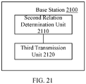
- a base station is provided, he base station being in a communication system, the communication system further including a user equipment, the base station having a plurality of transmission beams, wherein the base station comprising: a second relation determination unit configured to determine relations between blind decoding candidate resource blocks in a search space configuration and the transmission beams of the base station, the blind decoding candidate resource blocks including one or more time-frequency elements; a third transmission unit configured to determine a second transmission beam for transmitting downlink control information, and transmitting the downlink control information on the blind decoding candidate resource blocks corresponding to the determined second transmission beam according to the relations.
- the beam determination method, the demodulation method for the downlink transmission, and the corresponding user equipment and the base station performed by the communication system can enable the user equipment to determine the transmission beam of the base station through information interaction with the base station, and receive and decode, through selecting corresponding reception beam according to the determined transmission beam of the base station, the downlink control information and the downlink data information transmitted by the base station, thereby improving transmission quality of the information in the communication network.
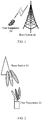
- the wireless communication system may include a base station 10 and a user equipment (UE) 20.
- the UE 20 may receive a downlink PDCCH and PDSCH transmitted by the base station 10.
- the base station 10 may be a transmission and reception point (TRP), or may schedule and manage a plurality of TRPs with a same central processor.
- TRP transmission and reception point
- the base station 10 may have a plurality of directional antennas, that is, a plurality of transmission beams, so that signals may be transmitted to the UE by using the plurality of transmission beams.
- the UE 20 may have a plurality of directional antennas, that is, a plurality of reception beams, so that signals transmitted by the base station may be received with the plurality of reception beams.
- the UE 20 may use all the reception beams to receive information transmitted by the base station, or may select a certain number of reception beams among all the reception beams to receive the information, and may also use a plurality of reception beams to form a quasi-omnidirectional antenna to receive the information.
- the UE 20 may have an omnidirectional antenna, so that the information is transmitted and received with only one beam (omnidirectional beam).
- a beam determination method of the embodiment of the present disclosure is applicable to both a scenario in which the UE 20 has a plurality of reception beams and a scenario in which the UE 20 has an omnidirectional antenna.
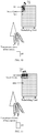
- FIG. 2 shows an exemplary diagram of information transmission according to an embodiment of the present disclosure.
- the base station 10 may form a plurality of transmission beams and the UE 20 may form a plurality of reception beams
- the UE 20 when the base station 10 transmits downlink control information (PDCCH) and/or downlink data information (PDSCH) to the UE 20, the UE 20 wants to know the transmission beam used by the base station 10 and preferably select reception beam corresponding to the transmission beam from the plurality of reception beams of UE to improve reception quality of the information. Therefore, it is necessary to enable the UE 20 to learn the transmission beam used by the base station for transmitting downlink information.
- PDCCH downlink control information
- PDSCH downlink data information
- Embodiments of the present disclosure provide a beam determination method for the base station and the user equipment, to enable the UE 20 to determine transmission beam used by the base station for transmitting the downlink control information and the downlink data information by utilizing information interaction between the base station 10 and the UE 20.
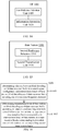
- FIG. 3 shows a beam determination method performed by a LTE according to the first embodiment of the present disclosure.
- the LTE can determine available transmission beam of the base station and reception beam of the UE corresponding to the available transmission beam, and receive downlink control information and downlink data information transmitted by the base station with this reception beam.
- step S301 CSI feedback for all or part of the transmission beams of the base station is transmitted to the base station. Specifically, for all or part of the transmission beams of the base station, the UE feeds back their corresponding CSI (Channel State Information) to the base station.
- the CSI fed back by the UE may be periodic feedback or non-periodic feedback.
- step S302 the UE determines, according to the CSI feedback for the transmission beams of the base station within a preset time window, a first transmission beam of the base station in all transmission beams of the base station for which there are CSI feedback within the range of the preset time window, and receives, through a first reception beam corresponding to the first transmission beam, the downlink control information transmitted by the base station through the first transmission beam.
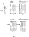
- FIG. 4 shows a schematic diagram of selecting corresponding transmission and reception beams at a base station side and a UE side according to the CSI feedback, respectively, in one embodiment of the present disclosure.
- the preset time window x may be predetermined and defined by LTE specification, or configured by RRC (Radio Resource Control) signaling.
- the preset time window x is a sliding window in one embodiment of the present disclosure.
- the length of the preset time window may be a fixed length x, while x being sliding change over the entire time axis, and for the base station, after the end of each time window of length x, the first transmission beam for transmitting downlink information is re-updated.
- the UE may also judge the first transmission beam available to the base station according to the predetermined rule after the end of each sliding time window x.
- the UE may expect to determine the first transmission beam available to the base station after a preset delay period y following each time window x, in order to have sufficient processing time to have a same understanding of beam update with the base station.
- This delay period y may also be predetermined and defined by the LTE specification, or configured by RRC signaling.
- the selection of the first transmission beam of the base station may follow a plurality of predetermined rules.
- the first transmission beam of the base station may be selected according to a parameter indicating a channel state in the CSI feedback for the transmission beams of the base station.
- the parameter indicating a channel state may be a CQI (Channel Quality Indicator).
- the method for determining the first transmission beam of the base station may include: selecting from the plurality of transmission beams of the base station, within the preset time window, a beam with a highest CQI as the first transmission beam; selecting, within the preset time window, a beam with a highest average CQI as the first transmission beam when the plurality of transmission beams of the base station have multiple CSI feedback and a plurality of CQI values are obtained; selecting from the plurality of transmission beams of the base station, within the preset time window, a beam whose CQI is greater than a predetermined threshold or a threshold configured by RRC and whose corresponding CSI feedback time is closest (that is, closest to an end point of the preset time window), as the first transmission beam; selecting, within the preset time window, a beam whose CQI is greater than the predetermined threshold for over a reference number of times and whose corresponding CSI feedback time is closest to the end point of the preset time window, or a beam whose average CQI is greater
- both the base station side and the UE side will follow the same rule to determine the transmission beam of the base station.
- the CQI value of the CSI feedback of the UE is 10; for the transmission beam b, the CQI value fed back by the UE is 13; for the transmission beam c, the CQI value fed back by the UE is 16; then again for the transmission beam a, the CQI value fed back by the UE is 11.
- the first transmission beam available to the base station may be selected according to the predetermined rule; while at the UE side, the first transmission beam available to the base station is determined after the preset delay period y following the preset time window of length x.
- the predetermined rule is to select the transmission beam with the highest CQI value
- both the base station side and the UE side will follow this rule to select the transmission beam c of the base station as the first transmission beam
- the UE side will receive, after having selected the transmission beam c as the first transmission beam of the base station, through the first reception beam 3 corresponding to the transmission beam c, the downlink information transmitted by the base station through the first transmission beam c.
- both the base station side and the UE side will select the transmission beam a as the first transmission beam, and the UE side will receive, through the first transmission beam 1 corresponding to the transmission beam a, the downlink control information transmitted by the base station.
- the predetermined threshold for example, 9
- the UE side may receive downlink control information (DCI) transmitted by the base station through a physical downlink control channel (PDCCH).
- DCI downlink control information
- the base station may have the following two options for a transmission mode of a physical downlink shared channel (PDSCH): 1) carrying out the PDSCH transmission through the above first transmission beam; 2) indicating the transmission beam for PDSCH transmission by information that indicates beams included in the DCI transmitted by the first transmission beam, and transmitting the downlink data information through the determined beam.
- PDSCH physical downlink shared channel
- the UE also needs to determine the transmission beams of the base station for PDSCH transmission for the above two modes of the base station respectively, and select the preferred reception beam corresponding thereto to receive the downlink data information.
- the transmission beam may be a CSI-RS based beam or an SS block based beam.
- the information that indicates a beam in the PDCCH beam in a RRC configuration signaling used for configuring relations of a beam-search space time-frequency resources related to PDCCH beam sweeping ,or in the DCI may include one or more of beam information (beam-index), channel state information reference signal port (CSI-RS port), channel state information reference signal configuration (CSI-RS configuration), beam reference signal configuration, codebook, code word, precoding information indication and Synchronization Signal (SS) block index.
- beam information beam-index
- CSI-RS port channel state information reference signal port
- CSI-RS configuration channel state information reference signal configuration
- codebook codebook
- code word code word
- precoding information indication precoding information indication
- the beam determination method performed in the communication system can enable the user equipment to determine the transmission beam of the base station by utilizing information interaction with the base station, and select, via its determined transmission beam of base station, the corresponding reception beam to receive the downlink control information an d the downlink data information transmitted by the base station, thereby improving transmission quality of the information in communication network.
- FIG. 6 shows the beam determination method performed by the base station according to the first embodiment of the present disclosure.
- the base station can determine the available transmission beam of the base station, and transmit the downlink control information and downlink data information through the transmission beam.
- the base station receives CSI feedback transmitted by the user equipment for all or part of the transmission beams of the base station. Specifically, for all or part of the transmission beams of the base station, the UE feeds back their corresponding CSI (channel state information) to the base station.
- the CSI fed back by the UE may be periodic feedback or non-periodic feedback.
- step S602 the base station determines, according to the CSI feedback for the transmission beams of the base station within a preset time window, a f ⁇ rst transmission beam of the base station in all transmission beams of the base station having CSI feedback within the range of the preset time window, and transmits the downlink control information through the first transmission beam.
- FIG. 4 shows the schematic diagram of selecting corresponding transmit and reception beams at the base station side and the UE side according to the CSI feedback, respectively, in one embodiment of the present disclosure. Wherein, before data transmission, it has been determined that three preferred transmission beams a, b, and c for the user in total at the base station side, and the reception beams corresponding to the transmission beams respectively at the UE side are 1, 2, and 3.
- the available transmission beam that meets the predetermined rule is selected at the base station side as the first transmission beam according to the CSI feedback of the UE for its respective transmission beams in the past preset time window x, and the downlink control information is transmitted through the selected first transmission beam.
- the preset time window x may be predetermined and defined by the LTE specification, or configured by the RRC (Radio Resource Control) signaling.
- FIG. 5 shows the schematic diagram of an example in which the preset time window x is the sliding window in one embodiment of the present disclosure.
- the length of the preset time window may be the fixed length x, while x being sliding change over the entire time axis, and for the base station, after the end of each time window of length x, the first transmission beam for transmitting downlink information is re-updated.
- the UE may also judge the first transmission beam available to the base station according to the predetermined rule after the end of each sliding time window x.
- the selection of the first transmission beam of the base station may follow the plurality of predetermined rules.
- the first transmission beam of the base station may be selected according to the parameter indicating a channel state in the CSI feedback for the transmission beams of the base station.
- the parameter indicating the channel state may be the CQI (Channel Quality Indicator).
- the method for determining the first transmission beam of the base station may include: selecting from the plurality of transmission beams of the base station, within the preset time window, the beam with a highest CQI as the first transmission beam; selecting, within the preset time window, the beam with the highest average CQI as the first transmission beam when the plurality of transmission beams of the base station have multiple CSI feedback and a plurality of CQI values are obtained; selecting from the plurality of transmission beams of the base station, within the preset time window, the beam whose CQI is greater than a predetermined threshold or a threshold configured by RRC and whose corresponding CSI feedback time is closest (that is, closest to the end point of the preset time window), as the first transmission beam; selecting, within the preset time window, the beam whose CQI is greater than the predetermined threshold for over a reference number of times and whose corresponding CSI feedback time is closest to the end point of the preset time window, or the beam whose average CQI is greater than the predetermined threshold and
- both the base station side and the UE side will follow the same rule to determine the transmission beam of the base station.
- the CQI value of the CSI feedback of the UE is 10; for the transmission beam b, the CQI value fed back by the UE is 13; for the transmission beam c, the CQI value fed back by the UE is 16; then again for the transmission beam a, the CQI value fed back by the UE is 11.
- the first transmission beam available to the base station may be selected according to the predetermined rule; while at the UE side, the first transmission beam available to the base station is determined after the preset delay period y following the preset time window of length x.
- the predetermined rule is to select the transmission beam with the highest CQI value
- both the base station side and the UE side will follow this rule to select the transmission beam c of the base station as the first transmission beam
- the UE side will receive, after having selected the transmission beam c as the first transmission beam of the base station, through the first reception beam 3 corresponding to the transmission beam c, the downlink information transmitted by the base station through the first transmission beam c.
- both the base station side and the UE side will select the transmission beam a as the first transmission beam, and the UE side will receive, through the first transmission beam 1 corresponding to the transmission beam a, the downlink control information transmitted by the base station.
- the predetermined threshold for example, 9
- the downlink information transmitted by the base station side may be the DCI transmitted through the physical downlink control channel (PDCCH).
- the base station when it is determined that the base station carries out PDCCH transmission through the first transmission beam, the base station may have the following two options for a transmission mode of a physical downlink shared channel (PDSCH): 1) carrying out the PDSCH transmission through the above first transmission beam; 2) indicating the transmission beam for PDSCH transmission by information that indicates beams included in the DCI transmitted by the first transmission beam, and transmitting the downlink data information through the determined beam.
- PDSCH physical downlink shared channel
- the UE also needs to determine the transmission beams of the base station for PDSCH transmission for the above two modes of the base station respectively, and select the preferred reception beam corresponding thereto to receive the downlink data information.
- the transmission beam may be a CSI-RS based beam or an SS block based beam.
- the information that indicates a beam in the PDCCH beam in a RRC configuration signaling used for configuring relations of a beam-search space time-frequency resources related to PDCCH beam sweeping ,or in the DCI may include one or more of beam information (beam-index), channel state information reference signal port (CSI-RS port), channel state information reference signal configuration (CSI-RS configuration), beam reference signal configuration, codebook, code word, precoding information indication and Synchronization Signal (SS) block index.
- beam information beam-index
- CSI-RS port channel state information reference signal port
- CSI-RS configuration channel state information reference signal configuration
- codebook codebook
- code word code word
- precoding information indication precoding information indication
- the beam determination method performed in the communication system can enable the user equipment to determine the transmission beam of the base station by utilizing information interaction with the base station, and select, via its determined transmission beam of base station, the corresponding reception beam to receive the downlink control information and the downlink data information transmitted by the base station , thereby improving transmission quality of the information in communication network.
- the UE may perform the beam determination method described above. Since the operation of the UE is substantially the same as the respective steps of the beam determination method described above, only a brief description of the UE is made herein, and a repeated description of the same content is omitted.
- a UE 700 includes a feedback unit 710 and a beam determination unit 720. It needs to be appreciated that FIG. 7 only shows means related to the embodiment of the present disclosure, while other means are omitted. But this is merely illustrative, and the UE 700 may include other means as needed.
- the feedback unit 710 may transmit CSI feedback for all or part of the transmission beams of the base station to the base station. Specifically, for all or part of the transmission beams of the base station, the feedback unit 710 feeds back their corresponding CSI (channel state information) to the base station.
- the CSI fed back by the UE may be periodic feedback or non-periodic feedback.
- the beam determination unit 720 may determine, according to the CSI feedback for the transmission beams of the base station within the preset time window, the first transmission beam of the base station in all transmission beams of the base station having CSI feedback within the preset time window, and receiving, through the first reception beam corresponding to the first transmission beam, downlink control information transmitted by the base station through the first transmission beam.
- FIG. 4 shows the schematic diagram of selecting corresponding transmit and reception beams at the base station side and the UE side according to the CSI feedback, respectively, in one embodiment of the present disclosure.
- the available transmission beam that meets the predetermined rule is selected at the base station side as the first transmission beam according to the CSI feedback of the UE for its respective transmission beams in the past preset time window x, and the downlink control information is transmitted through the selected first transmission beam.
- the preset time window x may be predetermined and defined by the LTE specification, or configured by the RRC (Radio Resource Control) signaling.
- the length of the preset time window may be the fixed length x, while x being sliding change over the entire time axis, and for the base station, after the end of each time window of length x, the first transmission beam for transmitting downlink information is re-updated.
- the UE may also judge the first transmission beam available to the base station according to the predetermined rule after the end of each sliding time window x.
- the UE may expect to determine the first transmission beam available to the base station after the preset delay period y following each time window x, in order to have sufficient processing time to have the same understanding of beam update with the base station.
- This delay period y may also be predetermined and defined by the LTE specification or configured by RRC signaling.
- the beam determination unit 720 may expect to determine the first transmission beam available to the base station after a preset delay period y following each time window x, in order to have sufficient processing time to have a same understanding of beam update with the base station.
- This delay period y may also be predetermined and defined by the LTE specification or configured by RRC signaling.
- the selection of the first transmission beam of the base station may follow the plurality of predetermined rules.
- the first transmission beam of the base station may be selected according to the parameter indicating a channel state in the CSI feedback for the transmission beams of the base station.
- the parameter indicating the channel state may be the CQI (Channel Quality Indicator).
- the method for determining the first transmission beam of the base station may include: selecting from the plurality of transmission beams of the base station, within the preset time window, the beam with a highest CQI as the first transmission beam; selecting, within the preset time window, the beam with the highest average CQI as the first transmission beam when the plurality of transmission beams of the base station have multiple CSI feedback and a plurality of CQI values are obtained; selecting from the plurality of transmission beams of the base station, within the preset time window, the beam whose CQI is greater than a predetermined threshold or a threshold configured by RRC and whose corresponding CSI feedback time is closest (that is, closest to the end point of the preset time window), as the first transmission beam; selecting, within the preset time window, the beam whose CQI is greater than the predetermined threshold for over a reference number of times and whose corresponding CSI feedback time is closest to the end point of the preset time window, or the beam whose average CQI is greater than the predetermined threshold and
- both the base station side and the UE side will follow the same rule to determine the transmission beam of the base station.
- the CQI value of the CSI feedback of the UE is 10; for the transmission beam b, the CQI value fed back by the UE is 13; for the transmission beam c, the CQI value fed back by the UE is 16; then again for the transmission beam a, the CQI value fed back by the UE is 11.
- the first transmission beam available to the base station may be selected according to the predetermined rule; while at the UE side, the first transmission beam available to the base station is determined by the beam determination unit 720 after the preset delay period y following the preset time window of length x.
- both the base station side and the UE side will follow this rule to select the transmission beam c of the base station as the first transmission beam, and the beam determination unit 720 at the UE side will receive, after having selected the transmission beam c as the first transmission beam of the base station, through the first reception beam 3 corresponding to the transmission beam c, the downlink information transmitted by the base station through the first transmission beam c.
- both the base station side and the UE side will select the transmission beam a as the first transmission beam, and the beam determination unit 720 at the UE side will receive, through the first transmission beam 1 corresponding to the transmission beam a, the downlink control information transmitted by the base station.
- the predetermined threshold for example, 9
- the beam determination unit 720 on the UE side may receive downlink control information (DCI) transmitted by the base station through the physical downlink control channel (PDCCH).
- DCI downlink control information
- the base station when it is determined that the base station carries out PDCCH transmission through the first transmission beam, the base station may have the following two options for a transmission mode of a physical downlink shared channel (PDSCH): 1) carrying out the PDSCH transmission through the above first transmission beam; 2) indicating the transmission beam for PDSCH transmission by information that indicates beams included in the DCI transmitted by the first transmission beam, and transmitting the downlink data information through the determined beam.
- PDSCH physical downlink shared channel
- the beam determination unit 720 also needs to determine the transmission beams of the base station for PDSCH transmission for the above two modes of the base station respectively, and select the preferred reception beam corresponding thereto to receive the downlink data information.
- the transmission beam may be a CSI-RS based beam or an SS block based beam.
- the information that indicates a beam in the PDCCH beam in a RRC configuration signaling used for configuring relations of a beam-search space time-frequency resources related to PDCCH beam sweeping, or in the DCI may include one or more of beam information (beam-index), channel state information reference signal port (CSI-RS port), channel state information reference signal configuration (CSI-RS configuration), beam reference signal configuration, codebook, code word, precoding information indication and Synchronization Signal (SS) block index.
- beam information beam-index
- CSI-RS port channel state information reference signal port
- CSI-RS configuration channel state information reference signal configuration
- codebook codebook
- code word code word
- precoding information indication precoding information indication
- the UE in the communication system can enable the user equipment to determine the transmission beam of the base station by utilizing information interaction with the base station, and select, via its determined transmission beam of base station, the corresponding reception beam to receive the downlink control information and the downlink data information transmitted by the base station, thereby improving transmission quality of the information in communication network.
- the base station may perform the beam determination method described above. Since the operation of the base station is substantially the same as the respective steps of the beam determination method described above, only a brief description of the UE is made herein, and a repeated description of the same content is omitted.
- a base station 800 includes a reception unit 810 and a first transmission unit 820. It needs to be appreciated that FIG. 8 only shows means related to embodiment of the present disclosure, while other means are omitted. But this is merely illustrative, and base station 800 may include other means as needed.
- the reception unit 810 receives CSI feedback transmitted by the user equipment for all or part of the transmission beams of the base station. Specifically, for all or part of the base station to transmission beams, the UE feeds back their corresponding CSI (channel state information) to the base station.
- the CSI fed back by the UE may be periodic feedback or non-periodic feedback.
- the first transmission unit 820 determines, according to the CSI feedback for the transmission beam of the base station within the preset time window, the first transmission beam of the base station in all transmission beams of the base station having CSI feedback within the preset time window, and transmitting the downlink control information through the first transmission beam.
- FIG. 4 shows the schematic diagram of selecting corresponding transmit and reception beams at the base station side and the UE side according to the CSI feedback, respectively, in one embodiment of the present disclosure. Wherein, before data transmission, it has been determined that three preferred transmission beams a, b, and c for the user in total at the base station side, and the reception beams corresponding to the transmission beams respectively at the UE side are 1, 2, and 3. As shown in FIG.
- the first transmission unit 820 at the base station side selects the available transmission beam that meets the predetermined rule as the first transmission beam according to the CSI feedback of the UE for its respective transmission beams in the past preset time window x, and transmits the downlink control information through the selected first transmission beam.
- the preset time window x may be predetermined, and defined by the LTE specification or configured by the RRC (Radio Resource Control) signaling.
- FIG. 5 shows the schematic diagram of an example in which the preset time window x is the sliding window in one embodiment of the present disclosure.
- the length of the preset time window may be the fixed length x, while x being sliding change over the entire time axis, and for the base station, after the end of each time window of length x, the first transmission beam for transmitting downlink information is re-updated by the first transmission unit 820.
- the UE may also judge the first transmission beam available to the base station according to the predetermined rule after the end of each sliding time window x.
- the selection of the first transmission beam of the base station by the first transmission unit 820 may follow the plurality of predetermined rules.
- the first transmission beam of the base station may be selected according to the parameter indicating a channel state in the CSI feedback for the transmission beams of the base station.
- the parameter indicating the channel state may be the CQI (Channel Quality Indicator).
- the method for determining the first transmission beam of the base station may include: selecting from the plurality of transmission beams of the base station, within the preset time window, the beam with a highest CQI as the first transmission beam; selecting, within the preset time window, the beam with the highest average CQI as the first transmission beam when the plurality of transmission beams of the base station have multiple CSI feedback and a plurality of CQI values are obtained; selecting from the plurality of transmission beams of the base station, within the preset time window, the beam whose CQI is greater than a predetermined threshold or a threshold configured by RRC and whose corresponding CSI feedback time is closest (that is, closest to the end point of the preset time window), as the first transmission beam; selecting, within the preset time window, the beam whose CQI is greater than the predetermined threshold for over a reference number of times and whose corresponding CSI feedback time is closest to the end point of the preset time window, or the beam whose average CQI is greater than the predetermined threshold and
- both the base station side and the UE side will follow the same rule to determine the transmission beam of the base station.
- the CQI value of the CSI feedback of the UE is 10; for the transmission beam b, the CQI value fed back by the UE is 13; for the transmission beam c, the CQI value fed back by the UE is 16; then again for the transmission beam a, the CQI value fed back by the UE is 11.
- the first transmission beam available to the base station may be selected by the first transmission unit 820 according to the predetermined rule; while at the UE side, the first transmission beam available to the base station is determined after the preset delay period y following the preset time window of length x.
- both the first transmission unit 820 at the base station side and the UE side will follow this rule to select the transmission beam c of the base station as the first transmission beam, and the UE side will receive, after having selected the transmission beam c as the first transmission beam of the base station, through the first reception beam 3 corresponding to the transmission beam c, the downlink information transmitted by the base station through the first transmission beam c.
- both the first transmission unit 820 at the base station side and the UE side will select the transmission beam a as the first transmission beam, and the UE side will receive, through the first transmission beam 1 corresponding to the transmission beam a, the downlink information transmitted by the base station.
- the predetermined threshold for example, 9
- the downlink information transmitted by the first transmission unit 820 at the base station side may be the DCI transmitted through the physical downlink control channel (PDCCH).
- the first transmission unit 820 at the base station may have the following two options for a transmission mode of a physical downlink shared channel (PDSCH): 1) carrying out the PDSCH transmission through the above first transmission beam; 2) indicating the transmission beam for PDSCH transmission by information that indicates beams included in the DCI transmitted by the first transmission beam, and transmitting the downlink data information through the determined beam.
- PDSCH physical downlink shared channel
- the UE also needs to separately determine the transmission beams of the base station for PDSCH transmission for the above two modes of the base station, and select the preferred reception beam corresponding thereto to receive the downlink data information.
- the transmission beam may be a CSI-RS based beam or an SS block based beam.
- the information that indicates a beam in the PDCCH beam in a RRC configuration signaling used for configuring relations of a beam-search space time-frequency resources related to PDCCH beam sweeping ,or in the DCI may include one or more of beam information (beam-index), channel state information reference signal port (CSI-RS port), channel state information reference signal configuration (CSI-RS configuration), beam reference signal configuration, codebook, code word, precoding information indication and Synchronization Signal (SS) block index.
- beam information beam-index
- CSI-RS port channel state information reference signal port
- CSI-RS configuration channel state information reference signal configuration
- codebook codebook
- code word code word
- precoding information indication precoding information indication
- the base station in the communication system provided according to the embodiment of the present disclosure can enable the user equipment to determine the transmission beam of the base station utilizing information interaction with the base station, and select, via its determined transmission beam of base station, the corresponding reception beam to receive the downlink control information and the downlink data information transmitted by the base station, thereby improving transmission quality of the information in communication network.
- FIG. 9 shows the demodulation method of downlink transmission performed by a UE according to the second embodiment of the present disclosure.
- the UE may determine a preset number N of preferred beams among M preferred beams in a plurality of transmission beams of the base station as well as reception beams of the UE corresponding to the preferred beams, and receive, with any one or more reception beams, downlink control information transmitted by the base station.
- the M preferred beams in the plurality of transmission beams of the base station are determined. Specifically before the downlink data transmission, the base station side and the UE side have jointly determined the M beams by using various methods, as beams that the base station may select when dynamically scheduling the UE. Wherein, both the UE side and the base station side may select M preferred beams from the plurality of transmission beams of the base station through a predetermined rule, and the selection basis may be according to previous channel state information or respective channel parameter values, or the like.
- the UE may transmit information of the M preferred beams to the base station; and when the M preferred beams are determined by the base station, the base station may also transmit the information of the preferred beams to the UE.
- the base station may configure the users to carry out feedback, and then the UEs may report to the base station the channel state parameter information such as their corresponding CSI or the like.
- step S902 the UE receives, through one or more reception beams corresponding to any one or more of N preferred beams in the M preferred beams, the downlink control information transmitted by the base station, wherein N ⁇ M, and the base station transmits signaling including the same downlink control information through the N preferred beams during the transmission time period of the downlink control information.
- the UE and the base station may also select again from the M preferred beams of the base station transmission beams according to a preset or configured beam configuration or the number of beams. For example, the UE may further select N beams (N ⁇ M) from the M preferred beams, so that the base station transmits the downlink control information through the N beams.
- N is the maximum number of repeated transmissions of the downlink control information transmitted on different beams.
- the configuration of the preset given number of N or the N beams herein may be defined by a LTE specification, or may be notified by broadcast information, for example, a master information block (MIB) or a system information block (SIB), or configured by a RRC signal.
- MIB master information block
- SIB system information block
- the base station will transmit a signaling including the downlink control information with the N preferred beams after learning the N preferred beams in the M preferred beams.
- the downlink control information contents transmitted by the base station through each of the N preferred beams are all the same. Therefore, at the UE side, the downlink control information transmitted by the base station may be received through the reception beams corresponding to any one or more of the N preferred beams. It may be known according to the transmitting manner in which the base station transmits the downlink control information in the embodiment of the present disclosure, the same downlink control information transmitted by the base station may be obtained regardless of the corresponding reception beam through which the UE receives.
- the UE and the base station do not need to select again in the M preferred beams, but directly carry out information transmission according to the determined M preferred beams.
- the UE may receive the downlink control information through the reception beams corresponding to one or more of the M preferred beams, and the UE may receive the same downlink control information for each corresponding reception beam.
- transmission of the signaling including the downlink control information transmitted by the base station side on different beams may be multiplexed according to a manner of code division multiplexing (CDM), time division multiplexing (TDM), or frequency division multiplexing (FDM), so that the signaling is transmitted in the manner of code division multiplexing, time division multiplexing or frequency division multiplexing on different beams at the base station side.
- CDM code division multiplexing
- TDM time division multiplexing
- FDM frequency division multiplexing
- the UE needs to carry out searching and information receiving in the search space with different beam sweeping patterns.
- the beam sweeping pattern herein may be preset by standard or defined by broadcast information or RRC or the like.
- the beam sweeping pattern is a CDM beam sweeping.
- FIG. 10 shows an exemplary diagram of search space CDM beam sweeping in the embodiment of the present disclosure.
- a horizontal axis represents time and a vertical axis represents frequency.
- search spaces of three preferred transmission beams a, b, and c of the base station are on the same time/frequency resources, and the RRC configures a plurality of beam-search space time/frequency resources related to PDCCH beam sweeping.
- the search space corresponding to each beam will all include the same DCI information.
- the UE will acquire the DCI information regardless of searching in the search space corresponding to a, b or c, and the UE may learn the transmission beams of the PDSCH through the information that indicates beams in the DCI by further decoding the DCI.
- the beam sweeping pattern is a TDM beam sweeping.
- FIG. 11 shows an exemplary diagram of search space TDM beam sweeping in the embodiment of the present disclosure.
- a horizontal axis represents time and a vertical axis represents frequency.
- the search spaces of the three preferred transmission beams a, b, and c of the base station are on different time resources, and the RRC configures a beam-search space time/frequency resource related to the PDCCH beam sweeping.
- the search space corresponding to each beam will all include the same DCI information.
- the UE will acquire the DCI information regardless of searching in the search space corresponding to a, b or c, and the UE may learn the transmission beams of the PDSCH through the information that indicates beams in the DCI by further decoding the DCI.
- the beam sweeping pattern is a FDM beam sweeping.
- FIG. 12 shows an exemplary diagram of search space FDM beam sweeping in the embodiment of the present disclosure.
- a horizontal axis represents time and a vertical axis represents frequency.
- the search spaces of the three preferred transmission beams a, b, and c of the base station are on different frequency resources, and the RRC configures a beam-search space time/frequency resource related to the PDCCH beam sweeping.
- the search space corresponding to each beam will all include the same DCI information.
- the UE will acquire the DCI information regardless of searching in the search space corresponding to a, b or c, and the UE may learn the transmission beams of the PDSCH through the information that indicates beams in the DCI by further decoding the DCI.
- the transmission beam may be a CSI-RS based beam or an SS block based beam.
- the information that indicates a beam in the PDCCH beam in a RRC configuration signaling used for configuring relations of a beam-search space time-frequency resources related to PDCCH beam sweeping ,or in the DCI may include one or more of beam information (beam-index), channel state information reference signal port (CSI-RS port), channel state information reference signal configuration (CSI-RS configuration), beam reference signal configuration, codebook, code word, precoding information indication and Synchronization Signal (SS) block index.
- the base station may inform the UE the transmission beam of the base station for transmitting downlink data information by the information that indicates beams included in the downlink control information. That is, the base station includes information for indicating the transmission beam of the PDSCH in the DCI, and transmits the DCI to the UE through all the N preferred beams.
- the base station may inform the UE the transmission beam of the PDSCH transmission adopted by the base station.
- the demodulation method for downlink transmission performed in the communication system can enable the user equipment to utilize the information interaction between the user equipment and the base station to determine the preferred beams in the plurality of transmission beams of the base station and the reception beams of the UE corresponding to the preferred beams, and utilize any one or more reception beams to receive the downlink control information transmitted by the base station , thereby improving the transmission quality of the information in the communication network.
- FIG. 13 shows the demodulation method of downlink transmission performed by the base station according to the second embodiment of the present disclosure.
- the base station may learn the preferred beam used by the base station to transmit the downlink control information, and transmit the downlink information through all the preferred transmission beams.
- step S1301 M preferred beams in a plurality of transmission beams of the base station are determined. Specifically, before the downlink data transmission, the base station side and the UE side have jointly determined the M beams by using various methods, as beams that the base station may select when dynamically scheduling the UE. Wherein, both the UE side and the base station side may select M preferred beams from the plurality of transmission beams of the base station through a predetermined rule, and the selection basis may be according to previous channel state information or respective channel parameter values, or the like.
- the UE may transmit information of the M preferred beams to the base station; and when the M preferred beams are determined by the base station, the base station may also transmit the information of the preferred beams to the UE.
- the base station may configure the users to carry out feedback, and then the base station may receive reported from the UE the channel state parameter information such as their corresponding CSI or the like.
- the base station may transmit signaling including the same downlink control information through N preferred beams in the M preferred beams, where N ⁇ M.
- both the UE and the base station may select again from the M preferred beams transmitted by the base station according to the preset number of beams.
- the UE may further select N beams (N ⁇ M) from the M preferred beams according to the preset or configured beam configuration or the number of beams, so that the base station transmits the downlink control information through the N beams.
- N is the maximum number of repeated transmissions of the downlink control information transmitted on different beams.
- the configuration of the preset given number of N or the N beams herein may be defined by the LTE specifications, or may be notified by broadcast information, for example, the MIB or the SIB, or configured by the RRC signal.
- the base station will transmit a signaling including the downlink control information with the N preferred beams after learning the N preferred beams in the M preferred beams.
- the downlink control information contents transmitted by the base station through each of the N preferred beams are all the same.
- the downlink control information transmitted by the base station may be received through the reception beams corresponding to any one or more of the N preferred beams. It may be known according to the transmitting manner in which the base station transmits the downlink control information in the embodiment of the present disclosure, the same downlink control information transmitted by the base station may be obtained regardless of the corresponding reception beam through which the UE receives.
- the UE and the base station do not need to select again in the M preferred beams, but directly carry out information transmission according to the determined M preferred beams.
- the UE may receive the downlink control information through the reception beams corresponding to one or more of the M preferred beams, and the UE may receive the same downlink control information for each corresponding reception beam.
- transmission of the signaling including the downlink control information transmitted by the base station side on different beams may be multiplexed according to a manner of code division multiplexing (CDM), time division multiplexing (TDM), or frequency division multiplexing (FDM), so that the signaling is transmitted in the manner of code division multiplexing, time division multiplexing or frequency division multiplexing on different beams at the base station side.
- CDM code division multiplexing
- TDM time division multiplexing
- FDM frequency division multiplexing
- the UE needs to carry out searching and information receiving in the search space with different beam sweeping patterns.
- the beam sweeping pattern herein may be preset by standard or defined by broadcast information or RRC or the like.
- the beam sweeping pattern is the CDM beam sweeping.
- FIG. 10 shows an exemplary diagram of search space CDM beam sweeping in the embodiment of the present disclosure.
- a horizontal axis represents time and a vertical axis represents frequency
- search spaces of three preferred transmission beams a, b, and c of the base station are on the same time/frequency resources, and the RRC configures the plurality of beam-search space time/frequency resources related to PDCCH beam sweeping.
- the search space corresponding to each beam will all include the same DCI information.
- the UE will acquire the DCI information regardless of searching in the search space corresponding to a, b or c, and the UE may learn the transmission beams of the PDSCH through the information that indicates beams in the DCI by further decoding the DCI.
- the beam sweeping pattern is the TDM beam sweeping.
- FIG. 11 shows an exemplary diagram of search space TDM beam sweeping in the embodiment of the present disclosure.
- a horizontal axis represents time and a vertical axis represents frequency.
- the search spaces of the three preferred transmission beams a, b, and c of the base station are on different time resources, and the RRC configures the beam-search space time/frequency resource related to the PDCCH beam sweeping.
- the search space corresponding to each beam will all include the same DCI information.
- the UE will acquire the DCI information regardless of searching in the search space corresponding to a, b or c, and the UE may learn the transmission beams of the PDSCH through the information that indicates beams in the DCI by further decoding the DCI.
- the beam sweeping pattern is the FDM beam sweeping.
- FIG. 12 shows an exemplary diagram of search space FDM beam sweeping in the embodiment of the present disclosure.
- a horizontal axis represents time and a vertical axis represents frequency.
- the search spaces of the three preferred transmission beams a, b, and c of the base station are on different frequency resources, and the RRC configures the beam-search space time/frequency resource related to the PDCCH beam sweeping.
- the search space corresponding to each beam will all include the same DCI information.
- the UE will acquire the DCI information regardless of searching in the search space corresponding to a, b or c, and the UE may learn the transmission beams of the PDSCH through the information that indicates beams in the DCI by further decoding the DCI.
- the transmission beam may be a CSI-RS based beam or an SS block based beam.
- the information that indicates a beam in the PDCCH beam in a RRC configuration signaling used for configuring relations of a beam-search space time-frequency resources related to PDCCH beam sweeping ,or in the DCI may include one or more of beam information (beam-index), channel state information reference signal port (CSI-RS port), channel state information reference signal configuration (CSI-RS configuration), beam reference signal configuration, codebook, code word, precoding information indication and Synchronization Signal (SS) block index.
- the base station may inform the UE the transmission beam of the base station for transmitting downlink data information by the information that indicates beams included in the downlink control information. That is, the base station includes information for indicating the transmission beam of the PDSCH in the DCI, and transmits the DCI to the UE through all the N preferred beams.
- the base station may inform the UE the transmission beam of the PDSCH transmission adopted by the base station.
- the demodulation method for downlink transmission performed in the communication system can enable the user equipment to utilize the information interaction between the user equipment and the base station to determine the preferred beams in the plurality of transmission beams of the base station and the reception beams of the UE corresponding to the preferred beams, and utilize any one or more reception beams to receive the downlink control information transmitted by the base station , thereby improving the transmission quality of the information in the communication network.
- the UE may perform the demodulation method for the downlink transmission described above. Since the operation of the UE is substantially the same as respective steps of the demodulation method for the downlink transmission described above, only a brief description thereof is made herein, and a repeated description of the same content is omitted.
- a UE 1400 includes a first preference selection unit 1410 and an information reception unit 1420. It needs to be appreciated that FIG. 14 only shows means related to the embodiment of the present disclosure, while other means are omitted. But this is merely illustrative, and the UE 1400 may include other means as needed.
- the first preference selection unit 1410 is configured to determine M preferred beams in a plurality of transmission beams of the base station. Specifically, before the downlink data transmission, the base station side and the UE side have jointly determined the M beams by using various methods, as beams that the base station may select when dynamically scheduling the UE. Wherein, both the UE side and the base station side may select M preferred beams from the plurality of transmission beams of the base station through a predetermined rule, and the selection basis may be according to previous channel state information or respective channel parameter values, or the like.
- the UE may transmit information of the M preferred beams to the base station; and when the M preferred beams are determined by the base station, the base station may also transmit the information of the preferred beams to the UE.
- the base station may configure the users to carry out feedback, and then the UEs may report to the base station the channel state parameter information such as their corresponding CSI or the like.
- the information reception unit 1420 is configured to receive, through one or more reception beams corresponding to any one or more of N preferred beams in the M preferred beams, the downlink control information transmitted by the base station, wherein N ⁇ M, the base station transmitting signaling including the same downlink control information through the N preferred beams during the transmission time period of the downlink control information.
- the UE and the base station may also select again from the M preferred beams of the base station transmission beams according to a preset or configured beam configuration or the number of beams.
- the information reception unit 1420 of the UE may further select N beams (N ⁇ M) from the M preferred beams, so that the base station transmits the downlink control information through the N beams.
- N is the maximum number of repeated transmissions of the downlink control information transmitted on different beams.
- the configuration of the preset given number of N or the N beams herein may be defined by the LTE specification, or may be notified by broadcast information, for example, the MIB or the SIB, or configured by the RRC signal.
- the base station will transmit a signaling including the downlink control information with the N preferred beams after learning the N preferred beams in the M preferred beams.
- the downlink control information contents transmitted by the base station through each of the N preferred beams are all the same. Therefore, at the UE side, the downlink control information transmitted by the base station may be received by the information reception unit 1420 through the reception beams corresponding to any one or more of the N preferred beams. It may be known according to the transmitting manner in which the base station transmits the downlink control information in the embodiment of the present disclosure, the same downlink control information transmitted by the base station may be obtained regardless of the corresponding reception beam through which the information reception unit 1420 of the UE receives.
- the UE and the base station do not need to select again in the M preferred beams, but directly carry out information transmission according to the determined M preferred beams.
- the information reception unit 1420 of the UE may receive the downlink control information through the reception beams corresponding to one or more of the M preferred beams, and the UE may receive the same downlink control information for each corresponding reception beam.
- transmission of the signaling including the downlink control information transmitted by the base station side on different beams may be multiplexed according to a manner of code division multiplexing (CDM), time division multiplexing (TDM), or frequency division multiplexing (FDM), so that the signaling is transmitted in the manner of code division multiplexing, time division multiplexing or frequency division multiplexing on different beams at the base station side.
- CDM code division multiplexing
- TDM time division multiplexing
- FDM frequency division multiplexing
- the information reception unit 1420 of the UE needs to carry out searching and information receiving in the search space with different beam sweeping patterns.
- the beam sweeping pattern herein may be preset by standard or defined by broadcast information or RRC or the like.
- the beam sweeping pattern is the CDM beam sweeping.
- FIG. 10 shows an exemplary diagram of search space CDM beam sweeping in the embodiment of the present disclosure.
- a horizontal axis represents time and a vertical axis represents frequency.
- search spaces of three preferred transmission beams a, b, and c of the base station are on the same time/frequency resources, and the RRC configures the plurality of beam-search space time/frequency resources related to PDCCH beam sweeping.
- the search space corresponding to each beam will all include the same DCI information.
- the information reception unit 1420 of the UE will acquire the DCI information regardless of searching in the search space corresponding to a, b or c, and the UE may learn the transmission beams of the PDSCH through the information that indicates beams in the DCI by further decoding the DCI.
- the beam sweeping pattern is the TDM beam sweeping.
- FIG. 11 shows an exemplary diagram of search space TDM beam sweeping in the embodiment of the present disclosure.
- a horizontal axis represents time and a vertical axis represents frequency.
- the search spaces of the three preferred transmission beams a, b, and c of the base station are on different time resources, and the RRC configures the beam-search space time/frequency resource related to the PDCCH beam sweeping.
- the search space corresponding to each beam will all include the same DCI information.
- the information reception unit 1420 of the UE will acquire the DCI information regardless of searching in the search space corresponding to a, b or c, and the UE may learn the transmission beams of the PDSCH through the information that indicates beams in the DCI by further decoding the DCI.
- the beam sweeping pattern is the FDM beam sweeping.
- FIG. 12 shows an exemplary diagram of search space FDM beam sweeping in the embodiment of the present disclosure.
- a horizontal axis represents time and a vertical axis represents frequency.
- the search spaces of the three preferred transmission beams a, b, and c of the base station are on different frequency resources, and the RRC configures the beam-search space time/frequency resource related to the PDCCH beam sweeping.
- the search space corresponding to each beam will all include the same DCI information.
- the information reception unit 1420 of the UE will acquire the DCI information regardless of searching in the search space corresponding to a, b or c, and the UE may learn the transmission beams of the PDSCH through the information that indicates beams in the DCI by further decoding the DCI.
- the transmission beam may be a CSI-RS based beam or an SS block based beam.
- the information that indicates a beam in the PDCCH beam in a RRC configuration signaling used for configuring relations of a beam-search space time-frequency resources related to PDCCH beam sweeping ,or in the DCI may include one or more of beam information (beam-index), channel state information reference signal port (CSI-RS port), channel state information reference signal configuration (CSI-RS configuration), beam reference signal configuration, codebook, code word, precoding information indication and Synchronization Signal (SS) block index.
- the base station may inform the UE the transmission beam of the base station for transmitting downlink data information by the information that indicates beams included in the downlink control information. That is, the base station includes information for indicating the transmission beam of the PDSCH in the DCI, and transmits the DCI to the UE through all the N preferred beams.
- the transmission beam of the PDSCH transmission adopted by the base station may be learned by the information reception unit 1420.
- the UE in the communication system can enable the user equipment to utilize the information interaction between the user equipment and the base station to determine the preferred beams in the plurality of transmission beams of the base station and the reception beams of the UE corresponding to the preferred beams, and utilize any one or more reception beams to receive the downlink control information transmitted by the base station , thereby improving the transmission quality of the information in the communication network.
- the base station may perform the demodulation method for the downlink transmission described above. Since the operation of the base station is substantially the same as respective steps of the demodulation method for the downlink transmission described above, only a brief description thereof is made herein, and a repeated description of the same content is omitted.
- a base station 1500 includes a second preference selection unit 1510 and a second transmission unit 1520. It needs to be appreciated that FIG. 15 only shows means related to embodiments of the present disclosure, while other means are omitted, but this is merely illustrative, and base station 1500 may include other means as needed.
- the second preference selection unit 1510 determines M preferred beams in a plurality of transmission beams of the base station. Specifically, before the downlink data transmission, the base station side and the UE side have jointly determined the M beams by using various methods, as beams that the base station may select when dynamically scheduling the UE. Wherein, both the UE side and the base station side may select M preferred beams from the plurality of transmission beams of the base station through a predetermined rule, and the selection basis may be according to previous channel state information or respective channel parameter values, or the like.
- the UE may transmit information of the M preferred beams to the base station; and when the M preferred beams are determined by the base station, the second preference selection unit 1510 of the base station may also transmit the information of the preferred beams to the UE.
- the base station may configure the users to carry out feedback, and then the base station may receive reported from the UE the channel state parameter information such as their corresponding CSI or the like.
- the second transmission unit 1520 transmits signaling including the same downlink control information through N preferred beams in the M preferred beams, where N ⁇ M.
- both the UE and the base station may select again from the M preferred beams transmitted by the base station according to the preset or configured beam configuration or the number of beams.
- the UE may further select N beams (N ⁇ M) from the M preferred beams, so that the base station transmits the downlink control information through the N beams.
- N is the maximum number of repeated transmissions of the downlink control information transmitted on different beams.
- the configuration of the preset given number of N or the N beams herein may be defined by the LTE specifications, or may be notified by broadcast information, for example, the MIB or the SIB, or configured by the RRC signal.
- the second transmission unit 1520 of the base station will transmit a signaling including the downlink control information with the N preferred beams after learning the N preferred beams in the M preferred beams.
- the downlink control information contents transmitted by the second transmission unit 1520 through each of the N preferred beams are all the same.
- the downlink control information transmitted by the base station may be received through the reception beams corresponding to any one or more of the N preferred beams. It may be known according to the transmitting manner in which the base station transmits the downlink control information in the embodiment of the present disclosure, the same downlink control information transmitted by the base station may be obtained regardless of the corresponding reception beam through which the UE receives.
- the UE and the base station do not need to select again in the M preferred beams, but directly carry out information transmission according to the determined M preferred beams.
- the UE may receive the downlink control information through the reception beams corresponding to one or more of the M preferred beams, and the UE may receive the same downlink control information for each corresponding reception beam.
- transmission of the signaling including the downlink control information transmitted by the second transmission unit 1520 of the base station side on different beams may be multiplexed according to a manner of code division multiplexing (CDM), time division multiplexing (TDM), or frequency division multiplexing (FDM), so that the signaling is transmitted in the manner of code division multiplexing, time division multiplexing or frequency division multiplexing on different beams at the base station side.
- CDM code division multiplexing
- TDM time division multiplexing
- FDM frequency division multiplexing
- the UE needs to carry out searching and information receiving in the search space with different beam sweeping patterns.
- the beam sweeping pattern herein may be preset by standard or defined by broadcast information or RRC or the like.
- the beam sweeping pattern is the CDM beam sweeping.
- FIG. 10 shows an exemplary diagram of search space CDM beam sweeping in the embodiment of the present disclosure.
- a horizontal axis represents time and a vertical axis represents frequency.
- search spaces of three preferred transmission beams a, b, and c of the base station are on the same time/frequency resources, and the RRC configures the plurality of beam-search space time/frequency resources related to PDCCH beam sweeping.
- the search space corresponding to each beam will all include the same DCI information.
- the UE will acquire the DCI information regardless of searching in the search space corresponding to a, b or c, and the UE may learn the transmission beams of the PDSCH through the information that indicates beams in the DCI by further decoding the DCI.
- the beam sweeping pattern is the TDM beam sweeping.
- FIG. 11 shows an exemplary diagram of search space TDM beam sweeping in the embodiment of the present disclosure.
- a horizontal axis represents time and a vertical axis represents frequency.
- the search spaces of the three preferred transmission beams a, b, and c of the base station are on different time resources, and the RRC configures the beam-search space time/frequency resource related to the PDCCH beam sweeping.
- the search space corresponding to each beam will all include the same DCI information.
- the UE will acquire the DCI information regardless of searching in the search space corresponding to a, b or c, and the UE may learn the transmission beams of the PDSCH through the information that indicates beams in the DCI by further decoding the DCI.
- the beam sweeping pattern is the FDM beam sweeping.
- FIG. 12 shows an exemplary diagram of search space FDM beam sweeping in the embodiment of the present disclosure.
- a horizontal axis represents time and a vertical axis represents frequency.
- the search spaces of the three preferred transmission beams a, b, and c of the base station are on different frequency resources, and the RRC configures the beam-search space time/frequency resource related to the PDCCH beam sweeping.
- the search space corresponding to each beam will all include the same DCI information.
- the UE will acquire the DCI information regardless of searching in the search space corresponding to a, b or c, and the UE may learn the transmission beams of the PDSCH through the information that indicates beams in the DCI by further decoding the DCI.
- the transmission beam may be the CSI-RS based beam or the SS block based beam.
- the information that indicates beams in the RRC configuration signaling or in the DCI, being in the PDCCH beam and used for configuring relations of the beam-search space time-frequency resource related to PDCCH beam sweeping may include one or more of beam information (beam-index), channel state information reference signal port (CSI-RS port), channel state information reference signal configuration (CSI-RS configuration), beam reference signal configuration, codebook, code word, precoding information indication and SS block index
- the second transmission unit 1520 may inform the UE the transmission beam of the base station for transmitting downlink data information by the information that indicates beams included in the downlink control information. That is, the base station includes information for indicating the transmission beam of the PDSCH in the DCI, and transmits the DCI to the UE through all the N preferred beams. At the UE side, by decoding the received DCI content, the transmission beam of the PDSCH transmission adopted by the base station may be learned.
- the base station in the communication system provided according to the embodiment of the present disclosure can enable the user equipment to utilize the information interaction between the user equipment and the base station to determine the preferred beams in the plurality of transmission beams of the base station and the reception beams of the UE corresponding to the preferred beams, and utilize any one or more reception beams to receive the downlink control information transmitted by the base station , thereby improving the transmission quality of the information in the communication network.
- FIG. 16 shows the demodulation method of downlink transmission performed by a UE according to the third embodiment of the present disclosure.
- the UE determines relations between candidate resource blocks of a blind decoding (BD) PDCCH in a search space configuration and the transmission beams of the base station, the blind decoding candidate resource blocks including one or more time-frequency elements.
- the relations between the blind decoding candidate resource blocks in the search space configuration and the transmission beams of the base station may be configured by the base station and notified to the UE by broadcast information (for example, MIB or SIB), or RRC signal.
- the UE determines the transmission beams of the base station on each blind decoding PDCCH candidate resource block according to the relations, and receives each blind decoding PDCCH candidate resource block using the reception beams corresponding to the transmission beams of the base station, to obtain resource blocks corresponding to the downlink control information and a corresponding second transmission beam.
- the base station may select the second transmission beam for transmitting downlink information, and transmit the downlink control information on the blind decoding candidate resource block corresponding to the transmission beam according to the relations.
- the UE may judge the corresponding transmission beam of the base station according to the relations, and search and attempt to receive information on the blind decoding candidate resource block with the reception beam corresponding to the transmission beam, so as to receive the downlink control information and its corresponding blind decoding candidate resource block and the corresponding second transmission beam of the base station.
- the UE does not receive the downlink control information on one blind decoding candidate resource block, it means that the base station does not select the transmission beam corresponding to the blind decoding candidate resource block to transmit information; and when the UE receives the downlink control information on one blind decoding candidate resource block, it means that the base station transmits the downlink control information with its corresponding second transmission beam.
- the method of the embodiment of the present invention may ensure the communication quality of the communication system.
- the blind decoding candidate resource blocks may have different aggregation levels (AL), and the blind decoding candidate resource blocks include different numbers of time-frequency elements at different aggregation levels.
- AL aggregation levels
- the aggregation levels may be changed compared to the LTE.
- the present invention is suitable for candidate resource blocks of the PDCCH of aggregation levels under any definition, and is also applicable to candidate resource blocks of the PDCCH that does not have the aggregation level.
- FIG. 17 shows a schematic diagram of a configuration of relations between the blind decoding candidate resource blocks and the transmission beams of the base station in the embodiment of the present disclosure.
- the candidate resource blocks may be arranged firstly by time domain resources and then by frequency domain resources, inside the PDCCH region, that is, the search space, or may be arranged firstly by the frequency domain resources and then by the time domain resources.
- FIG. 17 is an example of first arranging the time domain resource and then the frequency domain resource. As shown in FIG. 17 , there are three preferred transmission beams a, b, and c for the user in total at the base station side.
- the six candidate resource blocks may respectively correspond to the three transmission beams a, b, and c of the base station, and each candidate resource block may include one time-frequency element.
- each candidate resource block is twice the candidate resource block with aggregation level 1, and each includes two time-frequency elements, and the six candidate resource blocks may also correspond to the three transmission beams a, b, and c of the base station, respectively.
- each candidate resource block is four times of the candidate resource block with aggregation level 1, and each includes four time-frequency elements, and the two candidate resource blocks respectively correspond to the two transmission beams a and b of the base station.
- each candidate resource block is eight times of the candidate resource block with aggregation level 1, and each includes eight time-frequency elements, and the two candidate resource blocks respectively correspond to the two transmission beams b and c of the base station.
- the base station may determine the resource block corresponding to the second transmission beam according to the search space configuration in FIG. 17 after determining the aggregation level and the second transmission beam for transmitting the downlink control information.
- the base station when the base station, for example, determines to transmit the downlink information with a certain transmission beam as the second transmission beam according to channel condition, and the aggregation level is x, it may transmit according to the blind decoding candidate resource block with aggregation level x corresponding to the second transmission beam in the search space configuration.
- the UE when the UE carries out beam sweeping on the search space, for different blind decoding candidate resource blocks with different aggregation levels and their corresponding transmission beams, different reception beams will be selected to sweep. That is, for the resource block on which the base station actually transmits a downlink control channel, the UE will select the corresponding preferred reception beam to decode the resource block, thereby ensuring the information transmission quality.
- the base station when the base station transmits the downlink control channel on the resource block with aggregation level 2 using the transmission beam c, it may transmit according to the resource block corresponding to the transmission beam c and the aggregation level 2 in the search space configuration.
- the UE when the UE carries out beam sweeping on the search space, it will select different reception beams to sweep respectively for different blind decoding candidate resource blocks with the aggregation levels 1, 2, 4, and 8, where, when the UE sweeps to the blind decoding candidate resource block with aggregation level 2 corresponding to the transmission beam c, a preferred reception beam 3 corresponding to the transmission beam c will be selected to decode the resource block, thereby obtaining the downlink control information.
- FIG. 18 shows a schematic diagram of the configuration of the relations between the blind decoding candidate resource blocks and the transmission beams of the base station in the embodiment of the present disclosure, and the order of the search space is first arranging the time domain resource and then the frequency domain resource.
- the base station side may also have three preferred transmission beams a, b, c for the user in total.
- the aggregation level of the blind decoding candidate resource blocks is 1, six candidate resource blocks may respectively correspond to the three transmission beams a, b, and c of the base station, and each candidate resource block may include one time-frequency element.
- each candidate resource block is twice the candidate resource block with aggregation level 1, and each includes two time-trequency elements, and the six candidate resource blocks may also correspond to the three transmission beams a, b, and c of the base station, respectively.
- each candidate resource block is four times of the candidate resource block with aggregation level 1, and each includes four time-frequency elements, and the two candidate resource blocks respectively correspond to the two transmission beams a and b of the base station.
- each candidate resource block is eight times of the candidate resource block with aggregation level 1, and each includes eight time-frequency elements, and the two candidate resource blocks respectively correspond to the two transmission beams b and c of the base station.
- the base station may determine the resource block corresponding to the second transmission beam according to the search space configuration in FIG. 17 after determining the aggregation level and the second transmission beam for transmitting the downlink control information. For example, when the base station, for example, determines to transmit the downlink information with a certain transmission beam as the second transmission beam according to channel condition, and the aggregation level is x, it may transmit according to the blind decoding candidate resource block with aggregation level x corresponding to the second transmission beam in the search space configuration.
- the UE carries out beam sweeping on the search space, for different blind decoding candidate resource blocks with different aggregation levels and their corresponding transmission beams, different reception beams will be selected to sweep.
- the UE will select the corresponding preferred reception beam to decode the resource block, thereby ensuring the information transmission quality. For example, when the base station transmits the downlink control channel on the resource block with aggregation level 2 using the transmission beam c, it may transmit according to the resource block corresponding to the transmission beam c and the aggregation level 2 in the search space configuration.
- the UE when the UE carries out beam sweeping on the search space, for different blind decoding candidate resource blocks with aggregation levels 1, 2, 4, and 8, different reception beams will be selected respectively to sweep, wherein, when the UE sweeps to the blind decoding candidate resource block with aggregation level 2 corresponding to the transmission beam c , a preferred reception beam 3 corresponding to the transmission beam c will be selected to decode the resource block, thereby obtaining the downlink control information.
- the base station when the base station transmits PDCCH interaction information through the transmission beams, the base station may have the following two options for the transmitting mode of a physical downlink shared channel (PDSCH): 1) carrying out the PDSCH transmission through the above second transmission beam; 2) indicating the transmission beam for PDSCH transmission by information that indicates beams included in the DCI transmitted by the second transmission beams, and transmitting downlink data information through the determined beam.
- PDSCH physical downlink shared channel
- the UE also needs to separately determine the transmission beam of the base station for PDSCH transmission for the above two methods of the base station, and select the preferred reception beam corresponding thereto to receive.
- the DCI will not include information that indicates the beam, and the UE will judge that the PDSCH will transmit through the same second transmission beam as the PDCCH, and select the second reception beam to receive the downlink data information; and for the second case, when the UE decodes the DCI, the UE will determine the transmission beam of the PDSCH according to the information that indicates the beam included in the DCI and receive the downlink data information.
- the transmission beam may be a CSI-RS based beam or an SS block based beam.
- the information that indicates a beam in the PDCCH beam in a RRC configuration signaling used for configuring relations of a beam-search space time-frequency resources related to PDCCH beam sweeping ,or in the DCI may include one or more of beam information (beam-index), channel state information reference signal port (CSI-RS port), channel state information reference signal configuration (CSI-RS configuration), beam reference signal configuration, codebook, code word, precoding information indication and Synchronization Signal (SS) block index.
- beam information beam-index
- CSI-RS port channel state information reference signal port
- CSI-RS configuration channel state information reference signal configuration
- codebook codebook
- code word code word
- precoding information indication precoding information indication
- the demodulation method for the downlink transmission performed in the communication system can enable the user equipment to receive the downlink information transmitted by the base station with the preferred reception beam during beam sweeping through the preset search space configuration, thereby improving the transmission quality of the information in the communication network.
- FIG. 19 shows the demodulation method of the downlink transmission performed by the base station according to the third embodiment of the present disclosure.
- the base station may determine, according to the relations between the blind decoding candidate resource blocks in the search space configuration and the transmission beams of the base station, the blind decoding candidate resource block corresponding to the transmission beam used by the base station for transmitting the downlink information, and transmit the downlink control information accordingly.
- the base station determines the relations between the blind decoding (BD) PDCCH candidate resource blocks in the search space configuration and the transmission beams of the base station, the blind decoding candidate resource blocks including one or more time-frequency elements.
- the relations between the blind decoding candidate resource blocks in the search space configuration and the transmission beams of the base station may be configured by the base station, and notified to the UE by broadcast information (for example, MIB or SIB), or RRC signal, or may be predefined by the LTE specification.
- the base station determines second transmission beam for transmitting the downlink control information, and transmits the downlink control information on the blind decoding candidate resource blocks corresponding to the determined second transmission beam according to the relations. Specifically, after determining the preconfigured relations between the blind decoding candidate resource blocks in the search space configuration and the transmission beams of the base station, the base station may select the second transmission beam for transmitting downlink information, and transmit the downlink control information on the blind decoding candidate resource block corresponding to the transmission beam according to the relations.
- the UE may judge the corresponding transmission beam of the base station according to the relations, and search and attempt to receive information on the blind decoding candidate resource block with the reception beam corresponding to the transmission beam, so as to receive the downlink control information and its corresponding blind decoding candidate resource block and the corresponding second transmission beam of the base station.
- the UE does not receive the downlink control information on one blind decoding candidate resource block, it means that the base station does not select the transmission beam corresponding to the blind decoding candidate resource block to transmit information; and when the UE receives the downlink control information on one blind decoding candidate resource block, it means that the base station transmits the downlink control information with its corresponding second transmission beam .
- the method of the embodiment of the present invention may ensure the communication quality of the communication system.
- the blind decoding candidate resource blocks may have different aggregation levels (AL), and the blind decoding candidate resource blocks include different numbers of time-frequency elements at different aggregation levels.
- AL aggregation levels
- the aggregation levels may be changed compared to the LTE.
- the present invention is suitable for candidate resource blocks of the PDCCH of aggregation levels under any definition, and is also applicable to candidate resource blocks of the PDCCH that does not have the aggregation level.
- FIG. 17 shows a schematic diagram of a search space configuration of relations between the blind decoding candidate resource blocks and the transmission beams of the base station in the embodiment of the present disclosure.
- the candidate resource blocks may be inside the PDCCH region (that is, the search space) by first arranging a time domain resource and then a frequency domain resource, or may be inside the PDCCH region by first arranging the frequency domain resource and then the time domain resource.
- FIG. 17 is an example of first arranging the time domain resource and then the frequency domain resource.
- the base station side has three preferred transmission beams a, b, and c for the user in total.
- each candidate resource block may respectively correspond to the three transmission beams a, b, and c of the base station, and each candidate resource block may include one time-frequency element.
- each candidate resource block is twice the candidate resource block with aggregation level 1, and each includes two time-frequency elements, and the six candidate resource blocks may also correspond to the three transmission beams a, b, and c of the base station, respectively.
- each candidate resource block is four times of the candidate resource block with aggregation level 1, and each includes four time-frequency elements, and the two candidate resource blocks respectively correspond to the two transmission beams a and b of the base station.
- each candidate resource block is eight times of the candidate resource block with aggregation level 1, and each includes eight time-frequency elements, and the two candidate resource blocks respectively correspond to the two transmission beams b and c of the base station.
- the base station may determine the resource block corresponding to the second transmission beam according to the search space configuration in FIG. 17 after determining the aggregation level and the second transmission beam for transmitting the downlink control information.
- the base station when the base station, for example, determines to transmit the downlink information with a certain transmission beam as the second transmission beam according to channel condition, and the aggregation level is x, it may transmit according to the blind decoding candidate resource block with aggregation level x corresponding to the second transmission beam in the search space configuration.
- the UE when the UE carries out beam sweeping on the search space, for different blind decoding candidate resource blocks with different aggregation levels and their corresponding transmission beams, different reception beams will be selected to sweep. That is, for the resource block on which the base station actually transmits the downlink control channel, the UE will select the corresponding preferred reception beam to decode the resource block, thereby ensuring the information transmission quality.
- the base station when it transmits the downlink control channel on the resource block with aggregation level 2 using the transmission beam c, it may transmit according to the resource block corresponding to the transmission beam c and the aggregation level 2 in the search space configuration.
- the UE when the UE carries out beam sweeping on the search space, for different blind decoding candidate resource blocks with aggregation levels 1, 2, 4, and 8, different reception beams will be selected respectively to sweep, wherein, when the UE sweeps to the blind decoding candidate resource block with aggregation level 2 corresponding to the transmission beam c , a preferred reception beam 3 corresponding to the transmission beam c will be selected to decode the resource block, thereby obtaining the downlink control information.
- FIG. 18 shows a schematic diagram of the search space configuration of the relations between the blind decoding candidate resource blocks and the transmission beams of the base station in the embodiment of the present disclosure, and the order of the search space is first arranging the time domain resource and then the frequency domain resource.
- the base station side may also have three preferred transmission beams a, b, c for the user in total.
- the aggregation level of the blind decoding candidate resource blocks is 1, six candidate resource blocks may respectively correspond to the three transmission beams a, b, and c of the base station, and each candidate resource block may include one time-frequency element.
- each candidate resource block is twice the candidate resource block with aggregation level 1, and each includes two time-frequency elements, and the six candidate resource blocks may also correspond to the three transmission beams a, b, and c of the base station, respectively.
- each candidate resource block is four times of the candidate resource block with aggregation level 1, and each includes four time-frequency elements, and the two candidate resource blocks respectively correspond to the two transmission beams a and b of the base station.
- each candidate resource block is eight times of the candidate resource block with aggregation level 1, and each includes eight time-frequency elements, and the two candidate resource blocks respectively correspond to the two transmission beams b and c of the base station.
- the base station may determine the resource block corresponding to the second transmission beam according to the search space configuration in FIG. 17 after determining the aggregation level and the second transmission beam for transmitting the downlink control information. For example, when the base station, for example, determines to transmit the downlink information with a certain transmission beam as the second transmission beam according to channel condition, and the aggregation level is x, it may transmit according to the blind decoding candidate resource block with aggregation level x corresponding to the second transmission beam in the search space configuration.
- the UE carries out beam sweeping on the search space, for different blind decoding candidate resource blocks with different aggregation levels and their corresponding transmission beams, different reception beams will be selected to sweep.
- the UE will select the corresponding preferred reception beam to decode the resource block, thereby ensuring the information transmission quality. For example, when the base station transmits the downlink control channel on the resource block with aggregation level 2 using the transmission beam c, it may transmit according to the resource block corresponding to the transmission beam c and the aggregation level 2 in the search space configuration.
- the UE when the UE carries out beam sweeping on the search space, for different blind decoding candidate resource blocks with aggregation levels 1, 2, 4, and 8, different reception beams will be selected respectively to sweep, wherein, when the UE sweeps to the blind decoding candidate resource block with aggregation level 2 corresponding to the transmission beam c , a preferred reception beam 3 corresponding to the transmission beam c will be selected to decode the resource block, thereby obtaining the downlink control information.
- the base station when the base station transmits PDCCH interaction information through the transmission beams, the base station may have the following two options for the transmitting mode of a physical downlink shared channel (PDSCH): 1) carrying out the PDSCH transmission through the above the second transmission beam; 2) indicating the transmission beam for PDSCH transmission by information that indicates beams included in the DCI transmitted by the second transmission beams, and transmitting downlink data information through the determined beam.
- PDSCH physical downlink shared channel
- the UE also needs to separately determine the transmission beam of the base station for PDSCH transmission for the above two methods of the base station, and select the preferred reception beam corresponding thereto to receive.
- the DCI will not include information that indicates the beam, and the UE will judge that the PDSCH will transmit through the same second transmission beam as the PDCCH, and select the second reception beam to receive the downlink data information; and for the second case, when the UE decodes the DCI, the UE will determine the transmission beam of the PDSCH according to the information that indicates the beam included in the DCI and receive the downlink data information.
- the transmission beam may be a CSI-RS based beam or an SS block based beam.
- the information that indicates a beam in the PDCCH beam in a RRC configuration signaling used for configuring relations of a beam-search space time-frequency resources related to PDCCH beam sweeping ,or in the DCI may include one or more of beam information (beam-index), channel state information reference signal port (CSI-RS port), channel state information reference signal configuration (CSI-RS configuration), beam reference signal configuration, codebook, code word, precoding information indication and Synchronization Signal (SS) block index.
- beam information beam-index
- CSI-RS port channel state information reference signal port
- CSI-RS configuration channel state information reference signal configuration
- codebook codebook
- code word code word
- precoding information indication precoding information indication
- the demodulation method for the downlink transmission performed in the communication system can enable the user equipment to receive the downlink information transmitted by the base station with the preferred reception beam during beam sweeping through the preset search space configuration, thereby improving the transmission quality of the information in the communication network.
- the UE may perform the demodulation method for the downlink transmission described above. Since the operation of the UE is substantially the same as respective steps of the demodulation method for the downlink transmission described above, only a brief description thereof is made herein, and a repeated description of the same content is omitted.
- a UE 2000 includes a first relation determination unit 2010 and a blind decoding reception unit 2020. It needs to be appreciated that FIG. 20 only shows means related to embodiments of the present disclosure, while other means are omitted, but this is merely illustrative, and the UE 2000 may include other means as needed.
- the first relation determination unit 2010 may determine the relations between the blind decoding (BD) PDCCH candidate resource blocks in the search space configuration and the transmission beams of the base station, the blind decoding candidate resource blocks including one or more time-frequency elements.
- the relations between the blind decoding candidate resource blocks in the search space configuration and the transmission beams of the base station may be configured by the base station, and notified to the UE by broadcast information (for example, MIB or SIB), or RRC signal, or may be predefined by the LTE specification.
- the blind decoding reception unit 2020 may determine, on each blind decoding PDCCH candidate resource block according to the relations, the transmission beam of the base station, and receive, with the reception beams corresponding to the transmission beams of the base station, each blind decoding PDCCH candidate resource block, to obtain blind decoding candidate resource blocks corresponding to the downlink control information and the corresponding second transmission beam. Specifically, after determining the preconfigured relations between the blind decoding candidate resource blocks in the search space configuration and the transmission beams of the base station, the base station may select the second transmission beam for transmitting downlink information, and transmit the downlink control information on the blind decoding candidate resource block corresponding to the transmission beam according to the relations.
- the blind decoding reception unit 2020 may judge the corresponding transmission beam of the base station according to the relations, and search and attempt to receive information on the blind decoding candidate resource block with the reception beam corresponding to the transmission beam, so as to receive the downlink control information and its corresponding blind decoding candidate resource block and the corresponding second transmission beam of the base station.
- the blind decoding reception unit 2020 When the blind decoding reception unit 2020 does not receive the downlink control information on one blind decoding candidate resource block, it means that the base station does not select the transmission beam corresponding to the blind decoding candidate resource block to transmit information; and when the blind decoding reception unit 2020 receives the downlink control information on one blind decoding candidate resource block, it means that the base station transmits the downlink control information with its corresponding second transmission beam . Since the blind decoding reception unit 2020 has determined the transmission beam of the base station corresponding to the blind decoding candidate resource block according to the foregoing relations and has selected the preferred second reception beam corresponding to the second transmission beam to receive the information, the method of the embodiment of the present invention may ensure the communication quality of the communication system.
- the blind decoding candidate resource blocks may have different aggregation levels (AL), and the blind decoding candidate resource blocks include different numbers of time-frequency elements at different aggregation levels.
- AL aggregation levels
- the aggregation levels may be changed compared to the LTE.
- the present invention is suitable for candidate resource blocks of the PDCCH of aggregation levels under any definition, and is also applicable to candidate resource blocks of the PDCCH that does not have the aggregation level.
- FIG. 17 shows a schematic diagram of a search space configuration of relations between the blind decoding candidate resource blocks and the transmission beams of the base station in the embodiment of the present disclosure.
- the candidate resource blocks may be inside the PDCCH region, that is, the search space, by first arranging a time domain resource and then a frequency domain resource, or may be inside the PDCCH region by first arranging the frequency domain resource and then the time domain resource.
- FIG. 17 is an example of first arranging the time domain resource and then the frequency domain resource.
- the base station side has three preferred transmission beams a, b, and c for the user in total.
- each candidate resource block may respectively correspond to the three transmission beams a, b, and c of the base station, and each candidate resource block may include one time-frequency element.
- each candidate resource block is twice the candidate resource block with aggregation level 1, and each includes two time-frequency elements, and the six candidate resource blocks may also correspond to the three transmission beams a, b, and c of the base station, respectively.
- each candidate resource block is four times of the candidate resource block with aggregation level 1, and each includes four time-frequency elements, and the two candidate resource blocks respectively correspond to the two transmission beams a and b of the base station.
- each candidate resource block is eight times of the candidate resource block with aggregation level 1, and each includes eight time-frequency elements, and the two candidate resource blocks respectively correspond to the two transmission beams b and c of the base station.
- the base station may determine the resource block corresponding to the second transmission beam according to the search space configuration in FIG. 17 after determining the aggregation level and the second transmission beam for transmitting the downlink control information.
- the base station when the base station, for example, determines to transmit the downlink information with a certain transmission beam as the second transmission beam according to channel condition, and the aggregation level is x, it may transmit according to the blind decoding candidate resource block with aggregation level x corresponding to the second transmission beam in the search space configuration.
- the UE when the UE carries out beam sweeping on the search space, for different blind decoding candidate resource blocks with different aggregation levels and their corresponding transmission beams, different reception beams will be selected to sweep. That is, for the resource block on which the base station actually transmits the downlink control channel, the UE will select the corresponding preferred reception beam to decode the resource block, thereby ensuring the information transmission quality.
- the base station when it transmits the downlink control channel on the resource block with aggregation level 2 using the transmission beam c, it may transmit according to the resource block corresponding to the transmission beam c and the aggregation level 2 in the search space configuration.
- the UE when the UE carries out beam sweeping on the search space, for different blind decoding candidate resource blocks with aggregation levels 1, 2, 4, and 8, different reception beams will be selected respectively to sweep, wherein, when the UE sweeps to the blind decoding candidate resource block with aggregation level 2 corresponding to the transmission beam c , a preferred reception beam 3 corresponding to the transmission beam c will be selected to decode the resource block, thereby obtaining the downlink control information.
- FIG. 18 shows a schematic diagram of the search space configuration of the relations between the blind decoding candidate resource blocks and the transmission beams of the base station in the embodiment of the present disclosure, and the order of the search space is first arranging the time domain resource and then the frequency domain resource.
- the base station side may also have three preferred transmission beams a, b, c for the user in total.
- the aggregation level of the blind decoding candidate resource blocks is 1, six candidate resource blocks may respectively correspond to the three transmission beams a, b, and c of the base station, and each candidate resource block may include one time-frequency element.
- each candidate resource block is twice the candidate resource block with aggregation level 1, and each includes two time-frequency elements, and the six candidate resource blocks may also correspond to the three transmission beams a, b, and c of the base station, respectively.
- each candidate resource block is four times of the candidate resource block with aggregation level 1, and each includes four time-frequency elements, and the two candidate resource blocks respectively correspond to the two transmission beams a and b of the base station.
- each candidate resource block is eight times of the candidate resource block with aggregation level 1, and each includes eight time-frequency elements, and the two candidate resource blocks respectively correspond to the two transmission beams b and c of the base station.
- the base station may determine the resource block corresponding to the second transmission beam according to the search space configuration in FIG. 17 after determining the aggregation level and the second transmission beam for transmitting the downlink control information. For example, when the base station, for example, determines to transmit the downlink information with a certain transmission beam as the second transmission beam according to channel condition, and the aggregation level is x, it may transmit according to the blind decoding candidate resource block with aggregation level x corresponding to the second transmission beam in the search space configuration.
- the UE carries out beam sweeping on the search space, for different blind decoding candidate resource blocks with different aggregation levels and their corresponding transmission beams, different reception beams will be selected to sweep.
- the UE will select the corresponding preferred reception beam to decode the resource block, thereby ensuring the information transmission quality. For example, when the base station transmits the downlink control channel on the resource block with aggregation level 2 using the transmission beam c, it may transmit according to the resource block corresponding to the transmission beam c and the aggregation level 2 in the search space configuration.
- the UE when the UE carries out beam sweeping on the search space, for different blind decoding candidate resource blocks with aggregation levels 1, 2, 4, and 8, different reception beams will be selected respectively to sweep, wherein, when the UE sweeps to the blind decoding candidate resource block with aggregation level 2 corresponding to the transmission beam c , a preferred reception beam 3 corresponding to the transmission beam c will be selected to decode the resource block, thereby obtaining the downlink control information.
- the base station when the base station transmits PDCCH interaction information through the transmission beams, the base station may have the following two options for the transmitting mode of a physical downlink shared channel (PDSCH): 1) carrying out the PDSCH transmission through the above the second transmission beam; 2) indicating the transmission beam for PDSCH transmission by information that indicates beams included in the DCI transmitted by the second transmission beams, and transmitting downlink data information through the determined beam.
- PDSCH physical downlink shared channel
- the blind decoding reception unit 2020 of the UE also needs to separately determine the transmission beam of the base station for PDSCH transmission for the above two methods of the base station, and select the preferred reception beam corresponding thereto to receive.
- the DCI will not include information that indicates the beam
- the blind decoding reception unit 2020 of the UE will judge that the PDSCH will transmit through the same second transmission beam as the PDCCH, and select the second reception beam to receive the downlink data information
- the LTE will determine the transmission beam of the PDSCH according to the information that indicates the beam included in the DCI and receive the downlink data information.
- the transmission beam may be a CSI-RS based beam or an SS block based beam.
- the information that indicates a beam in the PDCCH beam in a RRC configuration signaling used for configuring relations of a beam-search space time-frequency resources related to PDCCH beam sweeping ,or in the DCI may include one or more of beam information (beam-index), channel state information reference signal port (CSI-RS port), channel state information reference signal configuration (CSI-RS configuration), beam reference signal configuration, codebook, code word, precoding information indication and Synchronization Signal (SS) block index.
- beam information beam-index
- CSI-RS port channel state information reference signal port
- CSI-RS configuration channel state information reference signal configuration
- codebook codebook
- code word code word
- precoding information indication precoding information indication
- the UE in the communication system can enable the user equipment to receive the downlink information transmitted by the base station with the preferred reception beam during beam sweeping through the preset search space configuration, thereby improving the transmission quality of the information in the communication network.
- the base station may perform the demodulation method for the downlink transmission described above. Since the operation of the base station is substantially the same as respective steps of the demodulation method for the downlink transmission described above, only a brief description thereof is made herein, and a repeated description of the same content is omitted.
- a base station 2100 includes a second relation determination unit 2110 and a third transmission unit 2120. It needs to be appreciated that FIG. 21 only shows means related to the embodiments of the present disclosure, while other means are omitted, but this is merely illustrative, and the base station 2100 may include other means as needed.
- the second relation determination unit 2110 can be used for determining the relations between the blind decoding (BD) PDCCH candidate resource blocks in the search space configuration and the transmission beams of the base station, the blind decoding candidate resource blocks including one or more time-frequency elements.
- the relations between the blind decoding candidate resource blocks in the search space configuration and the transmission beams of the base station may be configured by the base station, and notified to the UE by broadcast information (for example, MIB or SIB), or RRC signal, or may be predefined by the LTE specification.
- the third transmission unit 2120 determines second transmission beam for transmitting the downlink control information, and transmits the downlink control information on the blind decoding candidate resource blocks corresponding to the determined second transmission beam according to the relations. Specifically, after determining the preconfigured relations between the blind decoding candidate resource blocks in the search space configuration and the transmission beams of the base station, the third transmission unit 2120 may select the second transmission beam for transmitting downlink information, and transmit the downlink control information on the blind decoding candidate resource block corresponding to the transmission beam according to the relations.
- the UE may judge the corresponding transmission beam of the base station according to the relations, and search and attempt to receive information on the blind decoding candidate resource block with the reception beam corresponding to the transmission beam, so as to receive the downlink control information and its corresponding blind decoding candidate resource block and the corresponding second transmission beam of the base station.
- the UE does not receive the downlink control information on one blind decoding candidate resource block, it means that the base station does not select the transmission beam corresponding to the blind decoding candidate resource block to transmit information; and when the UE receives the downlink control information on one blind decoding candidate resource block, it means that the base station transmits the downlink control information with its corresponding second transmission beam .
- the method of the embodiment of the present invention may ensure the communication quality of the communication system.
- the blind decoding candidate resource blocks may have different aggregation levels (AL), and the blind decoding candidate resource blocks include different numbers of time-frequency elements at different aggregation levels.
- AL aggregation levels
- the aggregation levels may be changed compared to the LTE.
- the present invention is suitable for candidate resource blocks of the PDCCH of aggregation levels under any definition, and is also applicable to candidate resource blocks of the PDCCH that does not have the aggregation level.
- FIG. 17 shows a schematic diagram of a search space configuration of relations between the blind decoding candidate resource blocks and the transmission beams of the base station in the embodiment of the present disclosure.
- the candidate resource blocks may be inside the PDCCH region, that is, the search space, by first arranging a time domain resource and then a frequency domain resource, or may be inside the PDCCH region by first arranging the frequency domain resource and then the time domain resource.
- FIG. 17 is an example of first arranging the time domain resource and then the frequency domain resource.
- the base station side has three preferred transmission beams a, b, and c for the user in total.
- each candidate resource block may respectively correspond to the three transmission beams a, b, and c of the base station, and each candidate resource block may include one time-frequency element.
- each candidate resource block is twice the candidate resource block with aggregation level 1, and each includes two time-frequency elements, and the six candidate resource blocks may also correspond to the three transmission beams a, b, and c of the base station, respectively.
- each candidate resource block is four times of the candidate resource block with aggregation level 1, and each includes four time-frequency elements, and the two candidate resource blocks respectively correspond to the two transmission beams a and b of the base station.
- each candidate resource block is eight times of the candidate resource block with aggregation level 1, and each includes eight time-frequency elements, and the two candidate resource blocks respectively correspond to the two transmission beams b and c of the base station.
- the base station may determine the resource block corresponding to the second transmission beam according to the search space configuration in FIG. 17 after determining the aggregation level and the second transmission beam for transmitting the downlink control information.
- the base station when the base station, for example, determines to transmit the downlink information with a certain transmission beam as the second transmission beam according to channel condition, and the aggregation level is x, it may transmit according to the blind decoding candidate resource block with aggregation level x corresponding to the second transmission beam in the search space configuration.
- the UE when the UE carries out beam sweeping on the search space, for different blind decoding candidate resource blocks with different aggregation levels and their corresponding transmission beams, different reception beams will be selected to sweep. That is, for the resource block on which the base station actually transmits the downlink control channel, the UE will select the corresponding preferred reception beam to decode the resource block, thereby ensuring the information transmission quality.
- the base station when it transmits the downlink control channel on the resource block with aggregation level 2 using the transmission beam c, it may transmit according to the resource block corresponding to the transmission beam c and the aggregation level 2 in the search space configuration.
- the UE when the UE carries out beam sweeping on the search space, for different blind decoding candidate resource blocks with aggregation levels 1, 2, 4, and 8, different reception beams will be selected respectively to sweep, wherein, when the UE sweeps to the blind decoding candidate resource block with aggregation level 2 corresponding to the transmission beam c , a preferred reception beam 3 corresponding to the transmission beam c will be selected to decode the resource block, thereby obtaining the downlink control information.
- FIG. 18 shows a schematic diagram of the search space configuration of the relations between the blind decoding candidate resource blocks and the transmission beams of the base station in the embodiment of the present disclosure, and the order of the search space is first arranging the time domain resource and then the frequency domain resource.
- the base station side may also have three preferred transmission beams a, b, c for the user in total.
- the aggregation level of the blind decoding candidate resource blocks is 1, six candidate resource blocks may respectively correspond to the three transmission beams a, b, and c of the base station, and each candidate resource block may include one time-frequency element.
- each candidate resource block is twice the candidate resource block with aggregation level 1, and each includes two time-frequency elements, and the six candidate resource blocks may also correspond to the three transmission beams a, b, and c of the base station, respectively.
- each candidate resource block is four times of the candidate resource block with aggregation level 1, and each includes four time-frequency elements, and the two candidate resource blocks respectively correspond to the two transmission beams a and b of the base station.
- each candidate resource block is eight times of the candidate resource block with aggregation level 1, and each includes eight time-frequency elements, and the two candidate resource blocks respectively correspond to the two transmission beams b and c of the base station.
- the base station may determine the resource block corresponding to the second transmission beam according to the search space configuration in FIG. 17 after determining the aggregation level and the second transmission beam for transmitting the downlink control information. For example, when the base station, for example, determines to transmit the downlink information with a certain transmission beam as the second transmission beam according to channel condition, and the aggregation level is x, it may transmit according to the blind decoding candidate resource block with aggregation level x corresponding to the second transmission beam in the search space configuration.
- the UE carries out beam sweeping on the search space, for different blind decoding candidate resource blocks with different aggregation levels and their corresponding transmission beams , different reception beams will be selected to sweep.
- the UE will select the corresponding preferred reception beam to decode the resource block, thereby ensuring the information transmission quality. For example, when the base station transmits the downlink control channel on the resource block with aggregation level 2 using the transmission beam c, it may transmit according to the resource block corresponding to the transmission beam c and the aggregation level 2 in the search space configuration.
- the UE when the UE carries out beam sweeping on the search space, for different blind decoding candidate resource blocks with aggregation levels 1, 2, 4, and 8, different reception beams will be selected respectively to sweep, wherein, when the LTE sweeps to the blind decoding candidate resource block with aggregation level 2 corresponding to the transmission beam c , a preferred reception beam 3 corresponding to the transmission beam c will be selected to decode the resource block, thereby obtaining the downlink control information.
- the base station when the third transmission unit 2120 of the base station transmits PDCCH interaction information through the transmission beams, the base station may have the following two options for the transmitting mode of a physical downlink shared channel (PDSCH): 1) carrying out the PDSCH transmission through the above the second transmission beam; 2) indicating the transmission beam for PDSCH transmission by information that indicates beams included in the DCI transmitted by the second transmission beams, and transmitting downlink data information through the determined beam.
- PDSCH physical downlink shared channel
- the UE also needs to separately determine the transmission beam of the base station for PDSCH transmission for the above two methods of the base station, and select the preferred reception beam corresponding thereto to receive.
- the DCI transmitted by the third transmission unit 2120 will not include information that indicates the beam, and the UE will judge that the PDSCH will transmit through the same second transmission beam as the PDCCH, and select the second reception beam to receive the downlink data information; and for the second case, when the UE decodes the DCI, the UE will determine the transmission beam of the PDSCH according to the information that indicates the beam included in the DCI and receive the downlink data information
- the transmission beam may be a CSI-RS based beam or an SS block based beam.
- the information that indicates a beam in the PDCCH beam in a RRC configuration signaling used for configuring relations of a beam-search space time-frequency resources related to PDCCH beam sweeping ,or in the DCI may include one or more of beam information (beam-index), channel state information reference signal port (CSI-RS port), channel state information reference signal configuration (CSI-RS configuration), beam reference signal configuration, codebook, code word, precoding information indication and Synchronization Signal (SS) block index.
- beam information beam-index
- CSI-RS port channel state information reference signal port
- CSI-RS configuration channel state information reference signal configuration
- codebook codebook
- code word code word
- precoding information indication precoding information indication
- the base station in the communication system can enable the user equipment to receive the downlink information transmitted by the base station with the preferred reception beam during beam sweeping through the preset search space configuration, thereby improving the transmission quality of the information in the communication network.
Landscapes
- Engineering & Computer Science (AREA)
- Computer Networks & Wireless Communication (AREA)
- Signal Processing (AREA)
- Physics & Mathematics (AREA)
- Mathematical Physics (AREA)
- Mobile Radio Communication Systems (AREA)
Abstract
Description
- The present disclosure relates to a field of communications, and in particular to a determination method, a downlink transmission demodulation method performed in a communication system, and corresponding user equipment and base station.
- In a high-frequency scenario of 5G or in a scenario where a user equipment (UE) is connected to a 5G transmission and reception point (base station) or a long-term evolution (LTE) base station through dual connectivity, it is proposed to use a beam forming technique in the UE and the base station, that is, both the base station and the UE may use a plurality of beams for signal transmission and reception. Each transmission beam of the base station and each reception beam of the UE may form one downlink beam pair, and each reception beam of the base station and each transmission beam of the UE may form one uplink beam pair. However, neither the signal transmitted through each downlink beam pair can obtain good reception quality at the UE, nor the signal transmitted through each uplink beam pair can obtain good reception quality at the base station.
- Therefore, in order to improve the performance of a wireless communication system, in a transmission process of downlink control information and downlink data information, it is required to determine a preferred transmission beam of the base station and a preferred reception beam of the UE, so that the UE may use the preferred beam in the process of receiving downlink information transmitted by the base station. However, neither how to determine the preferred transmission beam of the base station and the preferred reception beam of the UE has not been proposed yet, nor how to demodulate the downlink control information and the downlink data information in downlink transmission to improve transmission quality.
- According to one embodiment of the present disclosure, there is provided a beam determination method performed by a user equipment in a communication system including a base station and a user equipment, the base station having a plurality of transmission beams, the method comprising: transmitting, to the base station, CSI feedback for a transmission beam of the base station; determining, according to the CSI feedback for the transmission beam of the base station within a preset time window, a first transmission beam of the base station in all transmission beams of the base station having CSI feedback within the preset time window, and receiving, through a first reception beam corresponding to the first transmission beam, downlink control information transmitted by the base station through the first transmission beam. The transmission beam may be a CSI-RS based beam or a Synchronization Signal Block (SS block) based beam.
- According to another embodiment of the present disclosure, there is provided a beam determination method performed by a base station in a communication system including a base station and a user equipment, the base station having a plurality of transmission beams, the method comprising: receiving CSI feedback transmitted by the user equipment for the transmission beam of the base station; determining, according to the CSI feedback for the transmission beam of the base station within a preset time window, a first transmission beam of the base station in all transmission beams of the base station having CSI feedback within the preset time window, and transmitting downlink control information through the first transmission beam.
- According to another embodiment of the present disclosure, there is provided a user equipment, the user equipment being in a communication system, the communication system further including a base station, the base station having a plurality of transmission beams, wherein the user equipment comprising: a feedback unit configured to transmit CSI feedback for a transmission beam of the base station to the base station; a beam determination unit configured to determine, according to the CSI feedback for the transmission beam of the base station within a preset time window, a first transmission beam of the base station in all transmission beams of the base station having CSI feedback within the preset time window, and receiving, through a first reception beam corresponding to the first transmission beam, downlink control information transmitted by the base station through the first transmission beam.
- According to another embodiment of the present disclosure, a base station is provided, the base station being in a communication system, the communication system further including a user equipment, the base station having a plurality of transmission beams, and the base station comprising: a reception unit configured to receive CSI feedback transmitted by the user equipment for the transmission beam of the base station; a first transmission unit configured to determine, according to the CSI feedback for the transmission beam of the base station within a preset time window, a first transmission beam of the base station in all transmission beams of the base station having CSI feedback within the preset time window, and transmitting downlink control information through the first transmission beam.
- According to another embodiment of the present disclosure, there is provided a demodulation method for downlink transmission performed by a user equipment in a communication system including a base station and a user equipment, the base station having a plurality of transmission beams, the method comprising: determining M preferred beams in the plurality of transmission beams of the base station; receiving, through one or more reception beams corresponding to any one or more of N preferred beams in the M preferred beams, downlink control information transmitted by the base station, wherein N≤M, the base station transmitting signaling including same downlink control information through the N preferred beams during the transmission time period of the downlink control information.
- According to another embodiment of the present disclosure, there is provided a demodulation method for downlink transmission performed by a base station in a communication system including a base station and a user equipment, the base station having a plurality of transmission beams, the method comprising: determining M preferred beams in the plurality of transmission beams of the base station; transmitting signaling including same downlink control information through N preferred beams in the M preferred beams, where N ≤M.
- According to another embodiment of the present disclosure, there is provided a user equipment, the user equipment being in a communication system, the communication system further including a base station, the base station having a plurality of transmission beams, wherein the user equipment comprising: a first preference selection unit, configured to determine M preferred beams in the plurality of transmission beams of the base station; an information reception unit configured to receive, through one or more reception beams corresponding to any one or more of N preferred beams in the M preferred beams, downlink control information transmitted by the base station, wherein N ≤ M, the base station transmitting signaling including same downlink control information through the N preferred beams during the transmission time period of the downlink control information.
- According to another embodiment of the present disclosure, there is provided a base station, the base station being in a communication system, the communication system further including a user equipment, the base station having a plurality of transmission beams, wherein the base station comprising: a second preference selection unit configured to determine M preferred beams in the plurality of transmission beams of the base station; a second transmission unit configured to transmit signaling including same downlink control information through N preferred beams in the M preferred beams, where N≤M.
- According to another embodiment of the present disclosure, there is provided a demodulation method for downlink transmission performed by a user equipment in a communication system including a base station and a user equipment, the base station having a plurality of transmission beams, the method comprising: determining relations between blind decoding candidate resource blocks in a search space configuration and the transmission beams of the base station, the blind decoding candidate resource blocks including one or more time-frequency elements; determining the transmission beam of the base station on the blind decoding candidate resource blocks according to the relations, and receiving downlink control information transmitted by the base station using reception beams corresponding to the transmission beams of the base station, to obtain resource blocks corresponding to the downlink control information and a corresponding second transmission beam.
- According to another embodiment of the present disclosure, there is provided a demodulation method for downlink transmission performed by a base station in a communication system including a base station and a user equipment, the base station having a plurality of transmission beams, the method comprising: determining relations between blind decoding PDCCH candidate resource blocks in a search space configuration and the transmission beams of the base station, the blind decoding PDCCH candidate resource blocks including one or more time-frequency elements; determining a second transmission beam for transmitting downlink control information, and transmitting the downlink control information on the blind decoding candidate resource blocks corresponding to the determined second transmission beam according to the relations.
- According to another embodiment of the present disclosure, there is provided a user equipment, the user equipment being in a communication system, the communication system further including a base station, the base station having a plurality of transmission beams, and the user equipment comprising: a first relation determination unit configured to determine relations between blind decoding PDCCH candidate resource blocks in a search space configuration and the transmission beams of the base station, the blind decoding candidate resource blocks including one or more time-frequency elements; a blind decoding reception unit configured to determine the transmission beam of the base station on the blind decoding candidate resource blocks according to the relations, and receiving downlink control information transmitted by the base station using reception beams corresponding to the transmission beams of the base station, to obtain resource blocks corresponding to the downlink control information and a corresponding second transmission beam.
- According to another embodiment of the present disclosure, a base station is provided, he base station being in a communication system, the communication system further including a user equipment, the base station having a plurality of transmission beams, wherein the base station comprising: a second relation determination unit configured to determine relations between blind decoding candidate resource blocks in a search space configuration and the transmission beams of the base station, the blind decoding candidate resource blocks including one or more time-frequency elements; a third transmission unit configured to determine a second transmission beam for transmitting downlink control information, and transmitting the downlink control information on the blind decoding candidate resource blocks corresponding to the determined second transmission beam according to the relations.
- The beam determination method, the demodulation method for the downlink transmission, and the corresponding user equipment and the base station performed by the communication system according to embodiments of the present disclosure, can enable the user equipment to determine the transmission beam of the base station through information interaction with the base station, and receive and decode, through selecting corresponding reception beam according to the determined transmission beam of the base station, the downlink control information and the downlink data information transmitted by the base station, thereby improving transmission quality of the information in the communication network.
- The above and other objects, features and advantages of the present disclosure will become more apparent by describing embodiments of the present disclosure in more details with reference to the drawings. The drawings are intended to provide a further understanding of the embodiments of the present disclosure, and to constitute a part of the specification, and are used to explain the present disclosure together with the embodiments of the present disclosure, and do not constitute a limitation for the present disclosure. In the drawings, the same reference numerals generally refer to the same parts or steps.
-
FIG. 1 is a schematic diagram of a mobile communication system according to an embodiment of the present disclosure; -
FIG. 2 schematically shows an exemplary diagram of information transmission of an embodiment of the present disclosure; -
FIG. 3 is a flowchart of a beam determination method performed by a user equipment according to a first embodiment of the present disclosure; -
FIG. 4 shows a schematic diagram of selecting transmission and reception beam at a base station side and a UE side respectively, in a first embodiment of the present disclosure; -
FIG. 5 shows a schematic diagram of an example in which a preset time window x is a sliding window in a first embodiment of the present disclosure; -
FIG. 6 shows a flowchart of a beam determination method performed by a base station according to a first embodiment of the present disclosure; -
FIG. 7 shows a block diagram of a structure of a UE according to a first embodiment of the present disclosure; -
FIG. 8 shows a block diagram of a structure of a base station according to a first embodiment of the present disclosure; -
FIG 9 shows a flowchart of a beam determination method performed by a user equipment according to a second embodiment of the present disclosure; -
FIG. 10 shows an exemplary diagram of search space CDM beam sweeping in a second embodiment of the present disclosure; -
FIG. 11 shows an exemplary diagram of search space TDM beam sweeping in a second embodiment of the present disclosure; -
FIG. 12 shows an exemplary diagram of search space FDM beam sweeping in a second embodiment of the present disclosure; -
FIG. 13 shows a flowchart of a beam determination method performed by a base station according to a second embodiment of the present disclosure; -
FIG. 14 shows a block diagram of a structure of a UE according to a second embodiment of the present disclosure; -
FIG. 15 shows a block diagram of a structure of a base station according to a second embodiment of the present disclosure; -
FIG. 16 shows a flowchart of a beam determination method performed by a user equipment according to a third embodiment of the present disclosure; -
FIG. 17 shows a schematic diagram of a search space configuration of a blind decoding candidate resource block in a third embodiment of the present disclosure; -
FIG. 18 shows a schematic diagram of a search space configuration of a blind decoding candidate resource block in a third embodiment of the present disclosure; -
FIG. 19 shows a flowchart of a beam determination method performed by a base station according to a third embodiment of the present disclosure; -
FIG. 20 shows a block diagram of a structure of a UE of a third embodiment of the present disclosure; -
FIG. 21 shows a block diagram of a structure of a base station of a third embodiment of the present disclosure. - In order to make the objects, technical solutions and advantages of the present disclosure more apparent, exemplary embodiments according to the present disclosure will be described in detail below with reference to the drawings. It is apparent that the described embodiments are only a part of the embodiments of the present disclosure, and not all of the embodiments of the present disclosure. It should be understood that the present disclosure is not limited to the exemplary embodiments described herein. Based on the embodiments of the present disclosure described in the present disclosure, all other embodiments obtained by a person skilled in the art without creative work are intended to fall within the protection scope of the present disclosure.
- Firstly a wireless communication system according to an embodiment of the present disclosure is described with reference to
FIG. 1 . As shown inFIG. 1 , the wireless communication system may include abase station 10 and a user equipment (UE) 20. The UE 20 may receive a downlink PDCCH and PDSCH transmitted by thebase station 10. It needs to be appreciated that although one base station and one UE are shown inFIG. 1 , this is merely illustrative and the wireless communication system may include one or more base stations and one or more UEs. Moreover, thebase station 10 may be a transmission and reception point (TRP), or may schedule and manage a plurality of TRPs with a same central processor. Hereinafter, terms "base station" and "TRP" can be used interchangeably. - In the above process, the
base station 10 may have a plurality of directional antennas, that is, a plurality of transmission beams, so that signals may be transmitted to the UE by using the plurality of transmission beams. Moreover, in some scenarios, the UE 20 may have a plurality of directional antennas, that is, a plurality of reception beams, so that signals transmitted by the base station may be received with the plurality of reception beams. Herein, the UE 20 may use all the reception beams to receive information transmitted by the base station, or may select a certain number of reception beams among all the reception beams to receive the information, and may also use a plurality of reception beams to form a quasi-omnidirectional antenna to receive the information. In some other scenarios, the UE 20 may have an omnidirectional antenna, so that the information is transmitted and received with only one beam (omnidirectional beam). A beam determination method of the embodiment of the present disclosure is applicable to both a scenario in which the UE 20 has a plurality of reception beams and a scenario in which the UE 20 has an omnidirectional antenna. -
FIG. 2 shows an exemplary diagram of information transmission according to an embodiment of the present disclosure. As shown inFIG. 2 , in the case that thebase station 10 may form a plurality of transmission beams and the UE 20 may form a plurality of reception beams, when thebase station 10 transmits downlink control information (PDCCH) and/or downlink data information (PDSCH) to the UE 20, the UE 20 wants to know the transmission beam used by thebase station 10 and preferably select reception beam corresponding to the transmission beam from the plurality of reception beams of UE to improve reception quality of the information. Therefore, it is necessary to enable the UE 20 to learn the transmission beam used by the base station for transmitting downlink information. - Embodiments of the present disclosure provide a beam determination method for the base station and the user equipment, to enable the UE 20 to determine transmission beam used by the base station for transmitting the downlink control information and the downlink data information by utilizing information interaction between the
base station 10 and the UE 20. - Hereinafter, a beam determination method according to the first embodiment of the present disclosure, in which a base station has a plurality of transmission beams, will be described.
-
FIG. 3 shows a beam determination method performed by a LTE according to the first embodiment of the present disclosure. Through this method, the LTE can determine available transmission beam of the base station and reception beam of the UE corresponding to the available transmission beam, and receive downlink control information and downlink data information transmitted by the base station with this reception beam. - As shown in
FIG. 3 , in step S301, CSI feedback for all or part of the transmission beams of the base station is transmitted to the base station. Specifically, for all or part of the transmission beams of the base station, the UE feeds back their corresponding CSI (Channel State Information) to the base station. The CSI fed back by the UE may be periodic feedback or non-periodic feedback. - In step S302, the UE determines, according to the CSI feedback for the transmission beams of the base station within a preset time window, a first transmission beam of the base station in all transmission beams of the base station for which there are CSI feedback within the range of the preset time window, and receives, through a first reception beam corresponding to the first transmission beam, the downlink control information transmitted by the base station through the first transmission beam.
FIG. 4 shows a schematic diagram of selecting corresponding transmission and reception beams at a base station side and a UE side according to the CSI feedback, respectively, in one embodiment of the present disclosure. Wherein, before data transmission, it has been determined that three preferred transmission beams a, b, and c for the user in total at the base station side, and the reception beams corresponding to the transmission beams respectively at the UE side are 1, 2, and 3. As shown inFIG. 4 , an available transmission beam that meets a predetermined rule is selected at the base station side as the first transmission beam according to the CSI feedback of the UE for its respective transmission beams in a past preset time window x, and the downlink control information is transmitted through the selected first transmission beam. In one embodiment of the present disclosure, the preset time window x may be predetermined and defined by LTE specification, or configured by RRC (Radio Resource Control) signaling.FIG. 5 shows a schematic diagram of an example in which the preset time window x is a sliding window in one embodiment of the present disclosure. Specifically, the length of the preset time window may be a fixed length x, while x being sliding change over the entire time axis, and for the base station, after the end of each time window of length x, the first transmission beam for transmitting downlink information is re-updated. Correspondingly, the UE may also judge the first transmission beam available to the base station according to the predetermined rule after the end of each sliding time window x. Returning toFIG. 4 , in a preferred embodiment, the UE may expect to determine the first transmission beam available to the base station after a preset delay period y following each time window x, in order to have sufficient processing time to have a same understanding of beam update with the base station. This delay period y may also be predetermined and defined by the LTE specification, or configured by RRC signaling. - In the foregoing embodiment, the selection of the first transmission beam of the base station may follow a plurality of predetermined rules. For example, the first transmission beam of the base station may be selected according to a parameter indicating a channel state in the CSI feedback for the transmission beams of the base station. Alternatively, the parameter indicating a channel state may be a CQI (Channel Quality Indicator). Specifically, the method for determining the first transmission beam of the base station may include: selecting from the plurality of transmission beams of the base station, within the preset time window, a beam with a highest CQI as the first transmission beam; selecting, within the preset time window, a beam with a highest average CQI as the first transmission beam when the plurality of transmission beams of the base station have multiple CSI feedback and a plurality of CQI values are obtained; selecting from the plurality of transmission beams of the base station, within the preset time window, a beam whose CQI is greater than a predetermined threshold or a threshold configured by RRC and whose corresponding CSI feedback time is closest (that is, closest to an end point of the preset time window), as the first transmission beam; selecting, within the preset time window, a beam whose CQI is greater than the predetermined threshold for over a reference number of times and whose corresponding CSI feedback time is closest to the end point of the preset time window, or a beam whose average CQI is greater than the predetermined threshold and whose corresponding CSI feedback time is closest to the end point of the preset time window, as the first transmission beam, when the plurality of transmission beams of the base station have a plurality of CSI feedback. Herein, once a beam selection rule is determined, both the base station side and the UE side will follow the same rule to determine the transmission beam of the base station. For example, in the embodiment shown in
FIG. 4 , in the time window x, for the transmission beam a of the base station, the CQI value of the CSI feedback of the UE is 10; for the transmission beam b, the CQI value fed back by the UE is 13; for the transmission beam c, the CQI value fed back by the UE is 16; then again for the transmission beam a, the CQI value fed back by the UE is 11. At the base station side, after the end of the time window of length x, the first transmission beam available to the base station may be selected according to the predetermined rule; while at the UE side, the first transmission beam available to the base station is determined after the preset delay period y following the preset time window of length x. In this embodiment, when the predetermined rule is to select the transmission beam with the highest CQI value, both the base station side and the UE side will follow this rule to select the transmission beam c of the base station as the first transmission beam, and the UE side will receive, after having selected the transmission beam c as the first transmission beam of the base station, through the first reception beam 3 corresponding to the transmission beam c, the downlink information transmitted by the base station through the first transmission beam c. When the predetermined rule is to select a beam whose CQI is greater than the predetermined threshold (for example, 9) and whose corresponding CSI feedback time is closest, both the base station side and the UE side will select the transmission beam a as the first transmission beam, and the UE side will receive, through thefirst transmission beam 1 corresponding to the transmission beam a, the downlink control information transmitted by the base station. - In one embodiment of the present disclosure, the UE side may receive downlink control information (DCI) transmitted by the base station through a physical downlink control channel (PDCCH). Moreover, in the embodiment of the present disclosure, when it is determined that the base station carries out PDCCH transmission through the first transmission beam, the base station may have the following two options for a transmission mode of a physical downlink shared channel (PDSCH): 1) carrying out the PDSCH transmission through the above first transmission beam; 2) indicating the transmission beam for PDSCH transmission by information that indicates beams included in the DCI transmitted by the first transmission beam, and transmitting the downlink data information through the determined beam. Correspondingly, the UE also needs to determine the transmission beams of the base station for PDSCH transmission for the above two modes of the base station respectively, and select the preferred reception beam corresponding thereto to receive the downlink data information. The transmission beam may be a CSI-RS based beam or an SS block based beam. The information that indicates a beam in the PDCCH beam in a RRC configuration signaling used for configuring relations of a beam-search space time-frequency resources related to PDCCH beam sweeping ,or in the DCI, may include one or more of beam information (beam-index), channel state information reference signal port (CSI-RS port), channel state information reference signal configuration (CSI-RS configuration), beam reference signal configuration, codebook, code word, precoding information indication and Synchronization Signal (SS) block index.
- The beam determination method performed in the communication system according to the embodiment of the present disclosure can enable the user equipment to determine the transmission beam of the base station by utilizing information interaction with the base station, and select, via its determined transmission beam of base station, the corresponding reception beam to receive the downlink control information an d the downlink data information transmitted by the base station, thereby improving transmission quality of the information in communication network.
- Hereinafter, a beam determination method performed by the base station according to the first embodiment of the present disclosure will be described. Since most of the operations of the method have been described above in describing the beam determination method performed by the UE, the description of the same content is omitted herein to avoid redundancy.
-
FIG. 6 shows the beam determination method performed by the base station according to the first embodiment of the present disclosure. Through this method, the base station can determine the available transmission beam of the base station, and transmit the downlink control information and downlink data information through the transmission beam. - As shown in
FIG. 6 , in step S601, the base station receives CSI feedback transmitted by the user equipment for all or part of the transmission beams of the base station. Specifically, for all or part of the transmission beams of the base station, the UE feeds back their corresponding CSI (channel state information) to the base station. The CSI fed back by the UE may be periodic feedback or non-periodic feedback. - In step S602, the base station determines, according to the CSI feedback for the transmission beams of the base station within a preset time window, a fírst transmission beam of the base station in all transmission beams of the base station having CSI feedback within the range of the preset time window, and transmits the downlink control information through the first transmission beam.
FIG. 4 shows the schematic diagram of selecting corresponding transmit and reception beams at the base station side and the UE side according to the CSI feedback, respectively, in one embodiment of the present disclosure. Wherein, before data transmission, it has been determined that three preferred transmission beams a, b, and c for the user in total at the base station side, and the reception beams corresponding to the transmission beams respectively at the UE side are 1, 2, and 3. As shown inFIG. 4 , the available transmission beam that meets the predetermined rule is selected at the base station side as the first transmission beam according to the CSI feedback of the UE for its respective transmission beams in the past preset time window x, and the downlink control information is transmitted through the selected first transmission beam. In one embodiment of the present disclosure, the preset time window x may be predetermined and defined by the LTE specification, or configured by the RRC (Radio Resource Control) signaling.FIG. 5 shows the schematic diagram of an example in which the preset time window x is the sliding window in one embodiment of the present disclosure. Specifically, the length of the preset time window may be the fixed length x, while x being sliding change over the entire time axis, and for the base station, after the end of each time window of length x, the first transmission beam for transmitting downlink information is re-updated. Correspondingly, the UE may also judge the first transmission beam available to the base station according to the predetermined rule after the end of each sliding time window x. - In the foregoing embodiment, the selection of the first transmission beam of the base station may follow the plurality of predetermined rules. For example, the first transmission beam of the base station may be selected according to the parameter indicating a channel state in the CSI feedback for the transmission beams of the base station. Alternatively, the parameter indicating the channel state may be the CQI (Channel Quality Indicator). Specifically, the method for determining the first transmission beam of the base station may include: selecting from the plurality of transmission beams of the base station, within the preset time window, the beam with a highest CQI as the first transmission beam; selecting, within the preset time window, the beam with the highest average CQI as the first transmission beam when the plurality of transmission beams of the base station have multiple CSI feedback and a plurality of CQI values are obtained; selecting from the plurality of transmission beams of the base station, within the preset time window, the beam whose CQI is greater than a predetermined threshold or a threshold configured by RRC and whose corresponding CSI feedback time is closest (that is, closest to the end point of the preset time window), as the first transmission beam; selecting, within the preset time window, the beam whose CQI is greater than the predetermined threshold for over a reference number of times and whose corresponding CSI feedback time is closest to the end point of the preset time window, or the beam whose average CQI is greater than the predetermined threshold and whose corresponding CSI feedback time is closest to the end point of the preset time window, as the first transmission beam, when the plurality of transmission beams of the base station have the plurality of CSI feedback. Herein, once the beam selection rule is determined, both the base station side and the UE side will follow the same rule to determine the transmission beam of the base station. For example, in the embodiment shown in
FIG. 4 , in the time window x, for the transmission beam a of the base station, the CQI value of the CSI feedback of the UE is 10; for the transmission beam b, the CQI value fed back by the UE is 13; for the transmission beam c, the CQI value fed back by the UE is 16; then again for the transmission beam a, the CQI value fed back by the UE is 11. At the base station side, after the end of the time window of length x, the first transmission beam available to the base station may be selected according to the predetermined rule; while at the UE side, the first transmission beam available to the base station is determined after the preset delay period y following the preset time window of length x. In this embodiment, when the predetermined rule is to select the transmission beam with the highest CQI value, both the base station side and the UE side will follow this rule to select the transmission beam c of the base station as the first transmission beam, and the UE side will receive, after having selected the transmission beam c as the first transmission beam of the base station, through the first reception beam 3 corresponding to the transmission beam c, the downlink information transmitted by the base station through the first transmission beam c. When the predetermined rule is to select the beam whose CQI is greater than the predetermined threshold (for example, 9) and whose corresponding CSI feedback time is closest, both the base station side and the UE side will select the transmission beam a as the first transmission beam, and the UE side will receive, through thefirst transmission beam 1 corresponding to the transmission beam a, the downlink control information transmitted by the base station. - In one embodiment of the present disclosure, the downlink information transmitted by the base station side may be the DCI transmitted through the physical downlink control channel (PDCCH). Moreover, in the embodiment of the present disclosure, when it is determined that the base station carries out PDCCH transmission through the first transmission beam, the base station may have the following two options for a transmission mode of a physical downlink shared channel (PDSCH): 1) carrying out the PDSCH transmission through the above first transmission beam; 2) indicating the transmission beam for PDSCH transmission by information that indicates beams included in the DCI transmitted by the first transmission beam, and transmitting the downlink data information through the determined beam. Correspondingly, the UE also needs to determine the transmission beams of the base station for PDSCH transmission for the above two modes of the base station respectively, and select the preferred reception beam corresponding thereto to receive the downlink data information. The transmission beam may be a CSI-RS based beam or an SS block based beam. The information that indicates a beam in the PDCCH beam in a RRC configuration signaling used for configuring relations of a beam-search space time-frequency resources related to PDCCH beam sweeping ,or in the DCI, may include one or more of beam information (beam-index), channel state information reference signal port (CSI-RS port), channel state information reference signal configuration (CSI-RS configuration), beam reference signal configuration, codebook, code word, precoding information indication and Synchronization Signal (SS) block index.
- The beam determination method performed in the communication system according to the embodiment of the present disclosure can enable the user equipment to determine the transmission beam of the base station by utilizing information interaction with the base station, and select, via its determined transmission beam of base station, the corresponding reception beam to receive the downlink control information and the downlink data information transmitted by the base station , thereby improving transmission quality of the information in communication network.
- Hereinafter, the UE according to the first embodiment of the present disclosure will be described with reference to
FIG. 7 . The UE may perform the beam determination method described above. Since the operation of the UE is substantially the same as the respective steps of the beam determination method described above, only a brief description of the UE is made herein, and a repeated description of the same content is omitted. - As shown in
FIG. 7 , aUE 700 includes afeedback unit 710 and abeam determination unit 720. It needs to be appreciated thatFIG. 7 only shows means related to the embodiment of the present disclosure, while other means are omitted. But this is merely illustrative, and theUE 700 may include other means as needed. - The
feedback unit 710 may transmit CSI feedback for all or part of the transmission beams of the base station to the base station. Specifically, for all or part of the transmission beams of the base station, thefeedback unit 710 feeds back their corresponding CSI (channel state information) to the base station. The CSI fed back by the UE may be periodic feedback or non-periodic feedback. - The
beam determination unit 720 may determine, according to the CSI feedback for the transmission beams of the base station within the preset time window, the first transmission beam of the base station in all transmission beams of the base station having CSI feedback within the preset time window, and receiving, through the first reception beam corresponding to the first transmission beam, downlink control information transmitted by the base station through the first transmission beam.FIG. 4 shows the schematic diagram of selecting corresponding transmit and reception beams at the base station side and the UE side according to the CSI feedback, respectively, in one embodiment of the present disclosure. Wherein, before data transmission, it has been determined that three preferred transmission beams a, b, and c for the user in total at the base station side, and the reception beams corresponding to the transmission beams respectively at the UE side are 1, 2, and 3. As shown inFIG. 4 , the available transmission beam that meets the predetermined rule is selected at the base station side as the first transmission beam according to the CSI feedback of the UE for its respective transmission beams in the past preset time window x, and the downlink control information is transmitted through the selected first transmission beam. In one embodiment of the present disclosure, the preset time window x may be predetermined and defined by the LTE specification, or configured by the RRC (Radio Resource Control) signaling.FIG. 5 shows the schematic diagram of an example in which the preset time window x is the sliding window in one embodiment of the present disclosure. Specifically the length of the preset time window may be the fixed length x, while x being sliding change over the entire time axis, and for the base station, after the end of each time window of length x, the first transmission beam for transmitting downlink information is re-updated. Correspondingly, the UE may also judge the first transmission beam available to the base station according to the predetermined rule after the end of each sliding time window x. Returning toFIG. 4 , in the preferred embodiment, the UE may expect to determine the first transmission beam available to the base station after the preset delay period y following each time window x, in order to have sufficient processing time to have the same understanding of beam update with the base station. This delay period y may also be predetermined and defined by the LTE specification or configured by RRC signaling. Returning toFIG. 4 , in the preferred embodiment, thebeam determination unit 720 may expect to determine the first transmission beam available to the base station after a preset delay period y following each time window x, in order to have sufficient processing time to have a same understanding of beam update with the base station. This delay period y may also be predetermined and defined by the LTE specification or configured by RRC signaling. - In the foregoing embodiment, the selection of the first transmission beam of the base station may follow the plurality of predetermined rules. For example, the first transmission beam of the base station may be selected according to the parameter indicating a channel state in the CSI feedback for the transmission beams of the base station. Alternatively, the parameter indicating the channel state may be the CQI (Channel Quality Indicator). Specifically, the method for determining the first transmission beam of the base station may include: selecting from the plurality of transmission beams of the base station, within the preset time window, the beam with a highest CQI as the first transmission beam; selecting, within the preset time window, the beam with the highest average CQI as the first transmission beam when the plurality of transmission beams of the base station have multiple CSI feedback and a plurality of CQI values are obtained; selecting from the plurality of transmission beams of the base station, within the preset time window, the beam whose CQI is greater than a predetermined threshold or a threshold configured by RRC and whose corresponding CSI feedback time is closest (that is, closest to the end point of the preset time window), as the first transmission beam; selecting, within the preset time window, the beam whose CQI is greater than the predetermined threshold for over a reference number of times and whose corresponding CSI feedback time is closest to the end point of the preset time window, or the beam whose average CQI is greater than the predetermined threshold and whose corresponding CSI feedback time is closest to the end point of the preset time window, as the first transmission beam, when the plurality of transmission beams of the base station have the plurality of CSI feedback. Herein, once the beam selection rule is determined, both the base station side and the UE side will follow the same rule to determine the transmission beam of the base station. For example, in the embodiment shown in
FIG. 4 , in the time window x, for the transmission beam a of the base station, the CQI value of the CSI feedback of the UE is 10; for the transmission beam b, the CQI value fed back by the UE is 13; for the transmission beam c, the CQI value fed back by the UE is 16; then again for the transmission beam a, the CQI value fed back by the UE is 11. At the base station side, after the end of the time window of length x, the first transmission beam available to the base station may be selected according to the predetermined rule; while at the UE side, the first transmission beam available to the base station is determined by thebeam determination unit 720 after the preset delay period y following the preset time window of length x. In this embodiment, when the predetermined rule is to select the transmission beam with the highest CQI value, both the base station side and the UE side will follow this rule to select the transmission beam c of the base station as the first transmission beam, and thebeam determination unit 720 at the UE side will receive, after having selected the transmission beam c as the first transmission beam of the base station, through the first reception beam 3 corresponding to the transmission beam c, the downlink information transmitted by the base station through the first transmission beam c. When the predetermined rule is to select the beam whose CQI is greater than the predetermined threshold (for example, 9) and whose corresponding CSI feedback time is closest, both the base station side and the UE side will select the transmission beam a as the first transmission beam, and thebeam determination unit 720 at the UE side will receive, through thefirst transmission beam 1 corresponding to the transmission beam a, the downlink control information transmitted by the base station. - In one embodiment of the present disclosure, the
beam determination unit 720 on the UE side may receive downlink control information (DCI) transmitted by the base station through the physical downlink control channel (PDCCH). Moreover, in the embodiment of the present disclosure, when it is determined that the base station carries out PDCCH transmission through the first transmission beam, the base station may have the following two options for a transmission mode of a physical downlink shared channel (PDSCH): 1) carrying out the PDSCH transmission through the above first transmission beam; 2) indicating the transmission beam for PDSCH transmission by information that indicates beams included in the DCI transmitted by the first transmission beam, and transmitting the downlink data information through the determined beam. Correspondingly, thebeam determination unit 720 also needs to determine the transmission beams of the base station for PDSCH transmission for the above two modes of the base station respectively, and select the preferred reception beam corresponding thereto to receive the downlink data information. The transmission beam may be a CSI-RS based beam or an SS block based beam. The information that indicates a beam in the PDCCH beam in a RRC configuration signaling used for configuring relations of a beam-search space time-frequency resources related to PDCCH beam sweeping, or in the DCI, may include one or more of beam information (beam-index), channel state information reference signal port (CSI-RS port), channel state information reference signal configuration (CSI-RS configuration), beam reference signal configuration, codebook, code word, precoding information indication and Synchronization Signal (SS) block index. - The UE in the communication system provided according to the embodiment of the present disclosure can enable the user equipment to determine the transmission beam of the base station by utilizing information interaction with the base station, and select, via its determined transmission beam of base station, the corresponding reception beam to receive the downlink control information and the downlink data information transmitted by the base station, thereby improving transmission quality of the information in communication network.
- Hereinafter, the base station according to the first embodiment of the present disclosure will be described with reference to
FIG. 8 . The base station may perform the beam determination method described above. Since the operation of the base station is substantially the same as the respective steps of the beam determination method described above, only a brief description of the UE is made herein, and a repeated description of the same content is omitted. - As shown in
FIG. 8 , abase station 800 includes areception unit 810 and afirst transmission unit 820. It needs to be appreciated thatFIG. 8 only shows means related to embodiment of the present disclosure, while other means are omitted. But this is merely illustrative, andbase station 800 may include other means as needed. - The
reception unit 810 receives CSI feedback transmitted by the user equipment for all or part of the transmission beams of the base station. Specifically, for all or part of the base station to transmission beams, the UE feeds back their corresponding CSI (channel state information) to the base station. The CSI fed back by the UE may be periodic feedback or non-periodic feedback. - The
first transmission unit 820 determines, according to the CSI feedback for the transmission beam of the base station within the preset time window, the first transmission beam of the base station in all transmission beams of the base station having CSI feedback within the preset time window, and transmitting the downlink control information through the first transmission beam.FIG. 4 shows the schematic diagram of selecting corresponding transmit and reception beams at the base station side and the UE side according to the CSI feedback, respectively, in one embodiment of the present disclosure. Wherein, before data transmission, it has been determined that three preferred transmission beams a, b, and c for the user in total at the base station side, and the reception beams corresponding to the transmission beams respectively at the UE side are 1, 2, and 3. As shown inFIG. 4 , thefirst transmission unit 820 at the base station side selects the available transmission beam that meets the predetermined rule as the first transmission beam according to the CSI feedback of the UE for its respective transmission beams in the past preset time window x, and transmits the downlink control information through the selected first transmission beam. In one embodiment of the present disclosure, the preset time window x may be predetermined, and defined by the LTE specification or configured by the RRC (Radio Resource Control) signaling.FIG. 5 shows the schematic diagram of an example in which the preset time window x is the sliding window in one embodiment of the present disclosure. Specifically, the length of the preset time window may be the fixed length x, while x being sliding change over the entire time axis, and for the base station, after the end of each time window of length x, the first transmission beam for transmitting downlink information is re-updated by thefirst transmission unit 820. Correspondingly, the UE may also judge the first transmission beam available to the base station according to the predetermined rule after the end of each sliding time window x. - In the foregoing embodiment, the selection of the first transmission beam of the base station by the
first transmission unit 820 may follow the plurality of predetermined rules. For example, the first transmission beam of the base station may be selected according to the parameter indicating a channel state in the CSI feedback for the transmission beams of the base station. Alternatively, the parameter indicating the channel state may be the CQI (Channel Quality Indicator). Specifically, the method for determining the first transmission beam of the base station may include: selecting from the plurality of transmission beams of the base station, within the preset time window, the beam with a highest CQI as the first transmission beam; selecting, within the preset time window, the beam with the highest average CQI as the first transmission beam when the plurality of transmission beams of the base station have multiple CSI feedback and a plurality of CQI values are obtained; selecting from the plurality of transmission beams of the base station, within the preset time window, the beam whose CQI is greater than a predetermined threshold or a threshold configured by RRC and whose corresponding CSI feedback time is closest (that is, closest to the end point of the preset time window), as the first transmission beam; selecting, within the preset time window, the beam whose CQI is greater than the predetermined threshold for over a reference number of times and whose corresponding CSI feedback time is closest to the end point of the preset time window, or the beam whose average CQI is greater than the predetermined threshold and whose corresponding CSI feedback time is closest to the end point of the preset time window, as the first transmission beam, when the plurality of transmission beams of the base station have the plurality of CSI feedback. Herein, once the beam selection rule is determined, both the base station side and the UE side will follow the same rule to determine the transmission beam of the base station. For example, in the embodiment shown inFIG. 4 , in the time window x, for the transmission beam a of the base station, the CQI value of the CSI feedback of the UE is 10; for the transmission beam b, the CQI value fed back by the UE is 13; for the transmission beam c, the CQI value fed back by the UE is 16; then again for the transmission beam a, the CQI value fed back by the UE is 11. At the base station side, after the end of the time window of length x, the first transmission beam available to the base station may be selected by thefirst transmission unit 820 according to the predetermined rule; while at the UE side, the first transmission beam available to the base station is determined after the preset delay period y following the preset time window of length x. In this embodiment, when the predetermined rule is to select the transmission beam with the highest CQI value, both thefirst transmission unit 820 at the base station side and the UE side will follow this rule to select the transmission beam c of the base station as the first transmission beam, and the UE side will receive, after having selected the transmission beam c as the first transmission beam of the base station, through the first reception beam 3 corresponding to the transmission beam c, the downlink information transmitted by the base station through the first transmission beam c. When the predetermined rule is to select the beam whose CQI is greater than the predetermined threshold (for example, 9) and whose corresponding CSI feedback time is closest, both thefirst transmission unit 820 at the base station side and the UE side will select the transmission beam a as the first transmission beam, and the UE side will receive, through thefirst transmission beam 1 corresponding to the transmission beam a, the downlink information transmitted by the base station. - In one embodiment of the present disclosure, the downlink information transmitted by the
first transmission unit 820 at the base station side may be the DCI transmitted through the physical downlink control channel (PDCCH). Moreover, in the embodiment of the present disclosure, when it is determined that the base station carries out PDCCH transmission through the first transmission beam, thefirst transmission unit 820 at the base station may have the following two options for a transmission mode of a physical downlink shared channel (PDSCH): 1) carrying out the PDSCH transmission through the above first transmission beam; 2) indicating the transmission beam for PDSCH transmission by information that indicates beams included in the DCI transmitted by the first transmission beam, and transmitting the downlink data information through the determined beam. Correspondingly, the UE also needs to separately determine the transmission beams of the base station for PDSCH transmission for the above two modes of the base station, and select the preferred reception beam corresponding thereto to receive the downlink data information. The transmission beam may be a CSI-RS based beam or an SS block based beam. The information that indicates a beam in the PDCCH beam in a RRC configuration signaling used for configuring relations of a beam-search space time-frequency resources related to PDCCH beam sweeping ,or in the DCI, may include one or more of beam information (beam-index), channel state information reference signal port (CSI-RS port), channel state information reference signal configuration (CSI-RS configuration), beam reference signal configuration, codebook, code word, precoding information indication and Synchronization Signal (SS) block index. - The base station in the communication system provided according to the embodiment of the present disclosure can enable the user equipment to determine the transmission beam of the base station utilizing information interaction with the base station, and select, via its determined transmission beam of base station, the corresponding reception beam to receive the downlink control information and the downlink data information transmitted by the base station, thereby improving transmission quality of the information in communication network.
- Hereinafter, a demodulation method of downlink transmission according to a second embodiment of the present disclosure, in which a base station has a plurality of transmission beams, will be described.
-
FIG. 9 shows the demodulation method of downlink transmission performed by a UE according to the second embodiment of the present disclosure. Through this method, the UE may determine a preset number N of preferred beams among M preferred beams in a plurality of transmission beams of the base station as well as reception beams of the UE corresponding to the preferred beams, and receive, with any one or more reception beams, downlink control information transmitted by the base station. - As shown in
FIG. 9 , in step S901, the M preferred beams in the plurality of transmission beams of the base station are determined. Specifically before the downlink data transmission, the base station side and the UE side have jointly determined the M beams by using various methods, as beams that the base station may select when dynamically scheduling the UE. Wherein, both the UE side and the base station side may select M preferred beams from the plurality of transmission beams of the base station through a predetermined rule, and the selection basis may be according to previous channel state information or respective channel parameter values, or the like. When the M preferred beams are determined by the UE, the UE may transmit information of the M preferred beams to the base station; and when the M preferred beams are determined by the base station, the base station may also transmit the information of the preferred beams to the UE. For example, as shown inFIG. 4 of the embodiment described above, the three transmission beams a, b and c at the base station side are the preferred beams mentioned herein. For the M preferred beams, the base station may configure the users to carry out feedback, and then the UEs may report to the base station the channel state parameter information such as their corresponding CSI or the like. - In step S902, the UE receives, through one or more reception beams corresponding to any one or more of N preferred beams in the M preferred beams, the downlink control information transmitted by the base station, wherein N ≤ M, and the base station transmits signaling including the same downlink control information through the N preferred beams during the transmission time period of the downlink control information.
- The UE and the base station may also select again from the M preferred beams of the base station transmission beams according to a preset or configured beam configuration or the number of beams. For example, the UE may further select N beams (N ≤ M) from the M preferred beams, so that the base station transmits the downlink control information through the N beams. N is the maximum number of repeated transmissions of the downlink control information transmitted on different beams The configuration of the preset given number of N or the N beams herein may be defined by a LTE specification, or may be notified by broadcast information, for example, a master information block (MIB) or a system information block (SIB), or configured by a RRC signal. In the embodiment of the present invention, the base station will transmit a signaling including the downlink control information with the N preferred beams after learning the N preferred beams in the M preferred beams. Wherein, the downlink control information contents transmitted by the base station through each of the N preferred beams are all the same. Therefore, at the UE side, the downlink control information transmitted by the base station may be received through the reception beams corresponding to any one or more of the N preferred beams. It may be known according to the transmitting manner in which the base station transmits the downlink control information in the embodiment of the present disclosure, the same downlink control information transmitted by the base station may be obtained regardless of the corresponding reception beam through which the UE receives.
- Certainly, in one embodiment of the present disclosure, the base station may also transmit signaling including the same downlink control information in the M preferred beams, that is, a case where N=M. At this time, the UE and the base station do not need to select again in the M preferred beams, but directly carry out information transmission according to the determined M preferred beams. Correspondingly, the UE may receive the downlink control information through the reception beams corresponding to one or more of the M preferred beams, and the UE may receive the same downlink control information for each corresponding reception beam.
- In the embodiment of the present disclosure, transmission of the signaling including the downlink control information transmitted by the base station side on different beams may be multiplexed according to a manner of code division multiplexing (CDM), time division multiplexing (TDM), or frequency division multiplexing (FDM), so that the signaling is transmitted in the manner of code division multiplexing, time division multiplexing or frequency division multiplexing on different beams at the base station side. Correspondingly, the UE needs to carry out searching and information receiving in the search space with different beam sweeping patterns. The beam sweeping pattern herein may be preset by standard or defined by broadcast information or RRC or the like.
- Specifically, in a first implementation of the embodiment of the disclosure, the beam sweeping pattern is a CDM beam sweeping.
FIG. 10 shows an exemplary diagram of search space CDM beam sweeping in the embodiment of the present disclosure. As shown inFIG. 10 , in one scheduling unit, a horizontal axis represents time and a vertical axis represents frequency. At this time, search spaces of three preferred transmission beams a, b, and c of the base station are on the same time/frequency resources, and the RRC configures a plurality of beam-search space time/frequency resources related to PDCCH beam sweeping. Wherein, the search space corresponding to each beam will all include the same DCI information. That is to say, the UE will acquire the DCI information regardless of searching in the search space corresponding to a, b or c, and the UE may learn the transmission beams of the PDSCH through the information that indicates beams in the DCI by further decoding the DCI. - In a second implementation of the embodiment of the present disclosure, the beam sweeping pattern is a TDM beam sweeping.
FIG. 11 shows an exemplary diagram of search space TDM beam sweeping in the embodiment of the present disclosure. As shown inFIG. 11 , in one scheduling unit, a horizontal axis represents time and a vertical axis represents frequency. At this time, the search spaces of the three preferred transmission beams a, b, and c of the base station are on different time resources, and the RRC configures a beam-search space time/frequency resource related to the PDCCH beam sweeping. Wherein, the search space corresponding to each beam will all include the same DCI information. That is to say, the UE will acquire the DCI information regardless of searching in the search space corresponding to a, b or c, and the UE may learn the transmission beams of the PDSCH through the information that indicates beams in the DCI by further decoding the DCI. - In a third implementation of the embodiment of the disclosure, the beam sweeping pattern is a FDM beam sweeping.
FIG. 12 shows an exemplary diagram of search space FDM beam sweeping in the embodiment of the present disclosure. As shown inFIG. 12 , in one scheduling unit, a horizontal axis represents time and a vertical axis represents frequency. At this time, the search spaces of the three preferred transmission beams a, b, and c of the base station are on different frequency resources, and the RRC configures a beam-search space time/frequency resource related to the PDCCH beam sweeping. Wherein, the search space corresponding to each beam will all include the same DCI information. That is to say, the UE will acquire the DCI information regardless of searching in the search space corresponding to a, b or c, and the UE may learn the transmission beams of the PDSCH through the information that indicates beams in the DCI by further decoding the DCI. - The transmission beam may be a CSI-RS based beam or an SS block based beam. The information that indicates a beam in the PDCCH beam in a RRC configuration signaling used for configuring relations of a beam-search space time-frequency resources related to PDCCH beam sweeping ,or in the DCI, may include one or more of beam information (beam-index), channel state information reference signal port (CSI-RS port), channel state information reference signal configuration (CSI-RS configuration), beam reference signal configuration, codebook, code word, precoding information indication and Synchronization Signal (SS) block index.
- In one embodiment of the present disclosure, the base station may inform the UE the transmission beam of the base station for transmitting downlink data information by the information that indicates beams included in the downlink control information. That is, the base station includes information for indicating the transmission beam of the PDSCH in the DCI, and transmits the DCI to the UE through all the N preferred beams. At the UE side, by decoding the received DCI content, the transmission beam of the PDSCH transmission adopted by the base station may be learned.
- The demodulation method for downlink transmission performed in the communication system provided according to the embodiment of the present disclosure can enable the user equipment to utilize the information interaction between the user equipment and the base station to determine the preferred beams in the plurality of transmission beams of the base station and the reception beams of the UE corresponding to the preferred beams, and utilize any one or more reception beams to receive the downlink control information transmitted by the base station , thereby improving the transmission quality of the information in the communication network.
- Hereinafter, a demodulation method of downlink transmission performed by the base station according to the second embodiment of the present disclosure will be described. Since most of the operations of the method have been described above in describing the demodulation method of downlink transmission performed by the UE, the description of the same content is omitted herein to avoid redundancy.
-
FIG. 13 shows the demodulation method of downlink transmission performed by the base station according to the second embodiment of the present disclosure. Through this method, the base station may learn the preferred beam used by the base station to transmit the downlink control information, and transmit the downlink information through all the preferred transmission beams. - As shown in
FIG. 13 , in step S1301, M preferred beams in a plurality of transmission beams of the base station are determined. Specifically, before the downlink data transmission, the base station side and the UE side have jointly determined the M beams by using various methods, as beams that the base station may select when dynamically scheduling the UE. Wherein, both the UE side and the base station side may select M preferred beams from the plurality of transmission beams of the base station through a predetermined rule, and the selection basis may be according to previous channel state information or respective channel parameter values, or the like. When the M preferred beams are determined by the UE, the UE may transmit information of the M preferred beams to the base station; and when the M preferred beams are determined by the base station, the base station may also transmit the information of the preferred beams to the UE. For example, as shown inFIG. 4 of the embodiment described above, the three transmission beams a, b and c at the base station side are the preferred beams mentioned herein. For the M preferred beams, the base station may configure the users to carry out feedback, and then the base station may receive reported from the UE the channel state parameter information such as their corresponding CSI or the like. - In step S1302, the base station may transmit signaling including the same downlink control information through N preferred beams in the M preferred beams, where N ≤ M. Wherein, both the UE and the base station may select again from the M preferred beams transmitted by the base station according to the preset number of beams. For example, the UE may further select N beams (N ≤ M) from the M preferred beams according to the preset or configured beam configuration or the number of beams, so that the base station transmits the downlink control information through the N beams. N is the maximum number of repeated transmissions of the downlink control information transmitted on different beams. The configuration of the preset given number of N or the N beams herein may be defined by the LTE specifications, or may be notified by broadcast information, for example, the MIB or the SIB, or configured by the RRC signal. In the embodiment of the present invention, the base station will transmit a signaling including the downlink control information with the N preferred beams after learning the N preferred beams in the M preferred beams. Wherein, the downlink control information contents transmitted by the base station through each of the N preferred beams are all the same. Correspondingly, at the UE side, the downlink control information transmitted by the base station may be received through the reception beams corresponding to any one or more of the N preferred beams. It may be known according to the transmitting manner in which the base station transmits the downlink control information in the embodiment of the present disclosure, the same downlink control information transmitted by the base station may be obtained regardless of the corresponding reception beam through which the UE receives.
- Certainly, in one embodiment of the present disclosure, the base station may also transmit signaling including the same downlink control information in the M preferred beams, that is, a case where N=M. At this time, the UE and the base station do not need to select again in the M preferred beams, but directly carry out information transmission according to the determined M preferred beams. Correspondingly, the UE may receive the downlink control information through the reception beams corresponding to one or more of the M preferred beams, and the UE may receive the same downlink control information for each corresponding reception beam.
- In the embodiment of the present disclosure, transmission of the signaling including the downlink control information transmitted by the base station side on different beams may be multiplexed according to a manner of code division multiplexing (CDM), time division multiplexing (TDM), or frequency division multiplexing (FDM), so that the signaling is transmitted in the manner of code division multiplexing, time division multiplexing or frequency division multiplexing on different beams at the base station side. Correspondingly, the UE needs to carry out searching and information receiving in the search space with different beam sweeping patterns. The beam sweeping pattern herein may be preset by standard or defined by broadcast information or RRC or the like.
- Specifically, in the first implementation of the embodiment of the disclosure, the beam sweeping pattern is the CDM beam sweeping.
FIG. 10 shows an exemplary diagram of search space CDM beam sweeping in the embodiment of the present disclosure. As shown inFIG. 10 , in one scheduling unit, a horizontal axis represents time and a vertical axis represents frequency At this time, search spaces of three preferred transmission beams a, b, and c of the base station are on the same time/frequency resources, and the RRC configures the plurality of beam-search space time/frequency resources related to PDCCH beam sweeping. Wherein, the search space corresponding to each beam will all include the same DCI information. That is to say, the UE will acquire the DCI information regardless of searching in the search space corresponding to a, b or c, and the UE may learn the transmission beams of the PDSCH through the information that indicates beams in the DCI by further decoding the DCI. - In the second implementation of the embodiment of the present disclosure, the beam sweeping pattern is the TDM beam sweeping.
FIG. 11 shows an exemplary diagram of search space TDM beam sweeping in the embodiment of the present disclosure. As shown inFIG. 11 , in one scheduling unit, a horizontal axis represents time and a vertical axis represents frequency. At this time, the search spaces of the three preferred transmission beams a, b, and c of the base station are on different time resources, and the RRC configures the beam-search space time/frequency resource related to the PDCCH beam sweeping. Wherein, the search space corresponding to each beam will all include the same DCI information. That is to say, the UE will acquire the DCI information regardless of searching in the search space corresponding to a, b or c, and the UE may learn the transmission beams of the PDSCH through the information that indicates beams in the DCI by further decoding the DCI. - In the third implementation of the embodiment of the disclosure, the beam sweeping pattern is the FDM beam sweeping.
FIG. 12 shows an exemplary diagram of search space FDM beam sweeping in the embodiment of the present disclosure. As shown inFIG. 12 , in one scheduling unit, a horizontal axis represents time and a vertical axis represents frequency. At this time, the search spaces of the three preferred transmission beams a, b, and c of the base station are on different frequency resources, and the RRC configures the beam-search space time/frequency resource related to the PDCCH beam sweeping. Wherein, the search space corresponding to each beam will all include the same DCI information. That is to say, the UE will acquire the DCI information regardless of searching in the search space corresponding to a, b or c, and the UE may learn the transmission beams of the PDSCH through the information that indicates beams in the DCI by further decoding the DCI. - The transmission beam may be a CSI-RS based beam or an SS block based beam. The information that indicates a beam in the PDCCH beam in a RRC configuration signaling used for configuring relations of a beam-search space time-frequency resources related to PDCCH beam sweeping ,or in the DCI, may include one or more of beam information (beam-index), channel state information reference signal port (CSI-RS port), channel state information reference signal configuration (CSI-RS configuration), beam reference signal configuration, codebook, code word, precoding information indication and Synchronization Signal (SS) block index.
- In one embodiment of the present disclosure, the base station may inform the UE the transmission beam of the base station for transmitting downlink data information by the information that indicates beams included in the downlink control information. That is, the base station includes information for indicating the transmission beam of the PDSCH in the DCI, and transmits the DCI to the UE through all the N preferred beams. At the UE side, by decoding the received DCI content, the transmission beam of the PDSCH transmission adopted by the base station may be learned.
- The demodulation method for downlink transmission performed in the communication system provided according to the embodiment of the present disclosure can enable the user equipment to utilize the information interaction between the user equipment and the base station to determine the preferred beams in the plurality of transmission beams of the base station and the reception beams of the UE corresponding to the preferred beams, and utilize any one or more reception beams to receive the downlink control information transmitted by the base station , thereby improving the transmission quality of the information in the communication network.
- Hereinafter, the UE according to the second embodiment of the present disclosure will be described with reference to
FIG. 14 . The UE may perform the demodulation method for the downlink transmission described above. Since the operation of the UE is substantially the same as respective steps of the demodulation method for the downlink transmission described above, only a brief description thereof is made herein, and a repeated description of the same content is omitted. - As shown in
FIG. 14 , aUE 1400 includes a firstpreference selection unit 1410 and aninformation reception unit 1420. It needs to be appreciated thatFIG. 14 only shows means related to the embodiment of the present disclosure, while other means are omitted. But this is merely illustrative, and theUE 1400 may include other means as needed. - The first
preference selection unit 1410 is configured to determine M preferred beams in a plurality of transmission beams of the base station. Specifically, before the downlink data transmission, the base station side and the UE side have jointly determined the M beams by using various methods, as beams that the base station may select when dynamically scheduling the UE. Wherein, both the UE side and the base station side may select M preferred beams from the plurality of transmission beams of the base station through a predetermined rule, and the selection basis may be according to previous channel state information or respective channel parameter values, or the like. When the M preferred beams are determined by the firstpreference selection unit 1410 of the UE, the UE may transmit information of the M preferred beams to the base station; and when the M preferred beams are determined by the base station, the base station may also transmit the information of the preferred beams to the UE. For example, as shown inFIG. 4 of the embodiment described above, the three transmission beams a, b and c at the base station side are the preferred beams mentioned herein. Optically, for the M preferred beams, the base station may configure the users to carry out feedback, and then the UEs may report to the base station the channel state parameter information such as their corresponding CSI or the like. - The
information reception unit 1420 is configured to receive, through one or more reception beams corresponding to any one or more of N preferred beams in the M preferred beams, the downlink control information transmitted by the base station, wherein N ≤M, the base station transmitting signaling including the same downlink control information through the N preferred beams during the transmission time period of the downlink control information. - The UE and the base station may also select again from the M preferred beams of the base station transmission beams according to a preset or configured beam configuration or the number of beams. For example, the
information reception unit 1420 of the UE may further select N beams (N ≤ M) from the M preferred beams, so that the base station transmits the downlink control information through the N beams. N is the maximum number of repeated transmissions of the downlink control information transmitted on different beams. The configuration of the preset given number of N or the N beams herein may be defined by the LTE specification, or may be notified by broadcast information, for example, the MIB or the SIB, or configured by the RRC signal. In the embodiment of the present invention, the base station will transmit a signaling including the downlink control information with the N preferred beams after learning the N preferred beams in the M preferred beams. Wherein, the downlink control information contents transmitted by the base station through each of the N preferred beams are all the same. Therefore, at the UE side, the downlink control information transmitted by the base station may be received by theinformation reception unit 1420 through the reception beams corresponding to any one or more of the N preferred beams. It may be known according to the transmitting manner in which the base station transmits the downlink control information in the embodiment of the present disclosure, the same downlink control information transmitted by the base station may be obtained regardless of the corresponding reception beam through which theinformation reception unit 1420 of the UE receives. - Certainly, in one embodiment of the present disclosure, the base station may also transmit signaling including the same downlink control information in the M preferred beams, that is, a case where N=M. At this time, the UE and the base station do not need to select again in the M preferred beams, but directly carry out information transmission according to the determined M preferred beams. Correspondingly, the
information reception unit 1420 of the UE may receive the downlink control information through the reception beams corresponding to one or more of the M preferred beams, and the UE may receive the same downlink control information for each corresponding reception beam. - In the embodiment of the present disclosure, transmission of the signaling including the downlink control information transmitted by the base station side on different beams may be multiplexed according to a manner of code division multiplexing (CDM), time division multiplexing (TDM), or frequency division multiplexing (FDM), so that the signaling is transmitted in the manner of code division multiplexing, time division multiplexing or frequency division multiplexing on different beams at the base station side. Correspondingly, the
information reception unit 1420 of the UE needs to carry out searching and information receiving in the search space with different beam sweeping patterns. The beam sweeping pattern herein may be preset by standard or defined by broadcast information or RRC or the like. - Specifically, in the first implementation of the embodiment of the disclosure, the beam sweeping pattern is the CDM beam sweeping.
FIG. 10 shows an exemplary diagram of search space CDM beam sweeping in the embodiment of the present disclosure. As shown inFIG. 10 , in one scheduling unit, a horizontal axis represents time and a vertical axis represents frequency. At this time, search spaces of three preferred transmission beams a, b, and c of the base station are on the same time/frequency resources, and the RRC configures the plurality of beam-search space time/frequency resources related to PDCCH beam sweeping. Wherein, the search space corresponding to each beam will all include the same DCI information. That is to say, theinformation reception unit 1420 of the UE will acquire the DCI information regardless of searching in the search space corresponding to a, b or c, and the UE may learn the transmission beams of the PDSCH through the information that indicates beams in the DCI by further decoding the DCI. - In the second implementation of the embodiment of the present disclosure, the beam sweeping pattern is the TDM beam sweeping.
FIG. 11 shows an exemplary diagram of search space TDM beam sweeping in the embodiment of the present disclosure. As shown inFIG. 11 , in one scheduling unit, a horizontal axis represents time and a vertical axis represents frequency. At this time, the search spaces of the three preferred transmission beams a, b, and c of the base station are on different time resources, and the RRC configures the beam-search space time/frequency resource related to the PDCCH beam sweeping. Wherein, the search space corresponding to each beam will all include the same DCI information. That is to say, theinformation reception unit 1420 of the UE will acquire the DCI information regardless of searching in the search space corresponding to a, b or c, and the UE may learn the transmission beams of the PDSCH through the information that indicates beams in the DCI by further decoding the DCI. - In the third implementation of the embodiment of the disclosure, the beam sweeping pattern is the FDM beam sweeping.
FIG. 12 shows an exemplary diagram of search space FDM beam sweeping in the embodiment of the present disclosure. As shown inFIG. 12 , in one scheduling unit, a horizontal axis represents time and a vertical axis represents frequency. At this time, the search spaces of the three preferred transmission beams a, b, and c of the base station are on different frequency resources, and the RRC configures the beam-search space time/frequency resource related to the PDCCH beam sweeping. Wherein, the search space corresponding to each beam will all include the same DCI information. That is to say, theinformation reception unit 1420 of the UE will acquire the DCI information regardless of searching in the search space corresponding to a, b or c, and the UE may learn the transmission beams of the PDSCH through the information that indicates beams in the DCI by further decoding the DCI. - The transmission beam may be a CSI-RS based beam or an SS block based beam. The information that indicates a beam in the PDCCH beam in a RRC configuration signaling used for configuring relations of a beam-search space time-frequency resources related to PDCCH beam sweeping ,or in the DCI, may include one or more of beam information (beam-index), channel state information reference signal port (CSI-RS port), channel state information reference signal configuration (CSI-RS configuration), beam reference signal configuration, codebook, code word, precoding information indication and Synchronization Signal (SS) block index.
- In one embodiment of the present disclosure, the base station may inform the UE the transmission beam of the base station for transmitting downlink data information by the information that indicates beams included in the downlink control information. That is, the base station includes information for indicating the transmission beam of the PDSCH in the DCI, and transmits the DCI to the UE through all the N preferred beams. At the UE side, by decoding the received DCI content, the transmission beam of the PDSCH transmission adopted by the base station may be learned by the
information reception unit 1420. - The UE in the communication system provided according to the embodiment of the present disclosure can enable the user equipment to utilize the information interaction between the user equipment and the base station to determine the preferred beams in the plurality of transmission beams of the base station and the reception beams of the UE corresponding to the preferred beams, and utilize any one or more reception beams to receive the downlink control information transmitted by the base station , thereby improving the transmission quality of the information in the communication network.
- Hereinafter, the base station according to the second embodiment of the present disclosure will be described with reference to
FIG. 15 . The base station may perform the demodulation method for the downlink transmission described above. Since the operation of the base station is substantially the same as respective steps of the demodulation method for the downlink transmission described above, only a brief description thereof is made herein, and a repeated description of the same content is omitted. - As shown in
FIG. 15 , abase station 1500 includes a second preference selection unit 1510 and asecond transmission unit 1520. It needs to be appreciated thatFIG. 15 only shows means related to embodiments of the present disclosure, while other means are omitted, but this is merely illustrative, andbase station 1500 may include other means as needed. - The second preference selection unit 1510 determines M preferred beams in a plurality of transmission beams of the base station. Specifically, before the downlink data transmission, the base station side and the UE side have jointly determined the M beams by using various methods, as beams that the base station may select when dynamically scheduling the UE. Wherein, both the UE side and the base station side may select M preferred beams from the plurality of transmission beams of the base station through a predetermined rule, and the selection basis may be according to previous channel state information or respective channel parameter values, or the like. When the M preferred beams are determined by the UE, the UE may transmit information of the M preferred beams to the base station; and when the M preferred beams are determined by the base station, the second preference selection unit 1510 of the base station may also transmit the information of the preferred beams to the UE. For example, as shown in
FIG. 4 of the embodiment described above, the three transmission beams a, b and c at the base station side are the preferred beams mentioned herein. Optically, for the M preferred beams, the base station may configure the users to carry out feedback, and then the base station may receive reported from the UE the channel state parameter information such as their corresponding CSI or the like. - The
second transmission unit 1520 transmits signaling including the same downlink control information through N preferred beams in the M preferred beams, where N ≤ M. Wherein, both the UE and the base station may select again from the M preferred beams transmitted by the base station according to the preset or configured beam configuration or the number of beams. For example, the UE may further select N beams (N ≤ M) from the M preferred beams, so that the base station transmits the downlink control information through the N beams. N is the maximum number of repeated transmissions of the downlink control information transmitted on different beams. The configuration of the preset given number of N or the N beams herein may be defined by the LTE specifications, or may be notified by broadcast information, for example, the MIB or the SIB, or configured by the RRC signal. In the embodiment of the present invention, thesecond transmission unit 1520 of the base station will transmit a signaling including the downlink control information with the N preferred beams after learning the N preferred beams in the M preferred beams. Wherein, the downlink control information contents transmitted by thesecond transmission unit 1520 through each of the N preferred beams are all the same. Correspondingly, at the UE side, the downlink control information transmitted by the base station may be received through the reception beams corresponding to any one or more of the N preferred beams. It may be known according to the transmitting manner in which the base station transmits the downlink control information in the embodiment of the present disclosure, the same downlink control information transmitted by the base station may be obtained regardless of the corresponding reception beam through which the UE receives. - Certainly, in one embodiment of the present disclosure, the
second transmission unit 1520 may also transmit signaling including the same downlink control information in the M preferred beams, that is, a case where N=M. At this time, the UE and the base station do not need to select again in the M preferred beams, but directly carry out information transmission according to the determined M preferred beams. Correspondingly, the UE may receive the downlink control information through the reception beams corresponding to one or more of the M preferred beams, and the UE may receive the same downlink control information for each corresponding reception beam. - In the embodiment of the present disclosure, transmission of the signaling including the downlink control information transmitted by the
second transmission unit 1520 of the base station side on different beams may be multiplexed according to a manner of code division multiplexing (CDM), time division multiplexing (TDM), or frequency division multiplexing (FDM), so that the signaling is transmitted in the manner of code division multiplexing, time division multiplexing or frequency division multiplexing on different beams at the base station side. Correspondingly, the UE needs to carry out searching and information receiving in the search space with different beam sweeping patterns. The beam sweeping pattern herein may be preset by standard or defined by broadcast information or RRC or the like. - Specifically, in the first implementation of the embodiment of the disclosure, the beam sweeping pattern is the CDM beam sweeping.
FIG. 10 shows an exemplary diagram of search space CDM beam sweeping in the embodiment of the present disclosure. As shown inFIG. 10 , in one scheduling unit, a horizontal axis represents time and a vertical axis represents frequency. At this time, search spaces of three preferred transmission beams a, b, and c of the base station are on the same time/frequency resources, and the RRC configures the plurality of beam-search space time/frequency resources related to PDCCH beam sweeping. Wherein, the search space corresponding to each beam will all include the same DCI information. That is to say, the UE will acquire the DCI information regardless of searching in the search space corresponding to a, b or c, and the UE may learn the transmission beams of the PDSCH through the information that indicates beams in the DCI by further decoding the DCI. - In the second implementation of the embodiment of the present disclosure, the beam sweeping pattern is the TDM beam sweeping.
FIG. 11 shows an exemplary diagram of search space TDM beam sweeping in the embodiment of the present disclosure. As shown inFIG. 11 , in one scheduling unit, a horizontal axis represents time and a vertical axis represents frequency. At this time, the search spaces of the three preferred transmission beams a, b, and c of the base station are on different time resources, and the RRC configures the beam-search space time/frequency resource related to the PDCCH beam sweeping. Wherein, the search space corresponding to each beam will all include the same DCI information. That is to say, the UE will acquire the DCI information regardless of searching in the search space corresponding to a, b or c, and the UE may learn the transmission beams of the PDSCH through the information that indicates beams in the DCI by further decoding the DCI. - In the third implementation of the embodiment of the disclosure, the beam sweeping pattern is the FDM beam sweeping.
FIG. 12 shows an exemplary diagram of search space FDM beam sweeping in the embodiment of the present disclosure. As shown inFIG. 12 , in one scheduling unit, a horizontal axis represents time and a vertical axis represents frequency. At this time, the search spaces of the three preferred transmission beams a, b, and c of the base station are on different frequency resources, and the RRC configures the beam-search space time/frequency resource related to the PDCCH beam sweeping. Wherein, the search space corresponding to each beam will all include the same DCI information. That is to say, the UE will acquire the DCI information regardless of searching in the search space corresponding to a, b or c, and the UE may learn the transmission beams of the PDSCH through the information that indicates beams in the DCI by further decoding the DCI. - Wherein, the transmission beam may be the CSI-RS based beam or the SS block based beam. The information that indicates beams in the RRC configuration signaling or in the DCI, being in the PDCCH beam and used for configuring relations of the beam-search space time-frequency resource related to PDCCH beam sweeping, may include one or more of beam information (beam-index), channel state information reference signal port (CSI-RS port), channel state information reference signal configuration (CSI-RS configuration), beam reference signal configuration, codebook, code word, precoding information indication and SS block index
- In one embodiment of the present disclosure, the
second transmission unit 1520 may inform the UE the transmission beam of the base station for transmitting downlink data information by the information that indicates beams included in the downlink control information. That is, the base station includes information for indicating the transmission beam of the PDSCH in the DCI, and transmits the DCI to the UE through all the N preferred beams. At the UE side, by decoding the received DCI content, the transmission beam of the PDSCH transmission adopted by the base station may be learned. - The base station in the communication system provided according to the embodiment of the present disclosure can enable the user equipment to utilize the information interaction between the user equipment and the base station to determine the preferred beams in the plurality of transmission beams of the base station and the reception beams of the UE corresponding to the preferred beams, and utilize any one or more reception beams to receive the downlink control information transmitted by the base station , thereby improving the transmission quality of the information in the communication network.
- Hereinafter, a demodulation method of downlink transmission according to the third embodiment of the present disclosure, in which a base station has a plurality of transmission beams, will be described.
-
FIG. 16 shows the demodulation method of downlink transmission performed by a UE according to the third embodiment of the present disclosure. With this method, through the relations between blind decoding candidate resource blocks in a predetermined search space and transmission beams of the base station, the UE searches in the search space by utilizing corresponding reception beams to receive downlink control information transmitted by the base station. - As shown in
FIG. 16 , in step S1601, the UE determines relations between candidate resource blocks of a blind decoding (BD) PDCCH in a search space configuration and the transmission beams of the base station, the blind decoding candidate resource blocks including one or more time-frequency elements. Specifically, the relations between the blind decoding candidate resource blocks in the search space configuration and the transmission beams of the base station may be configured by the base station and notified to the UE by broadcast information (for example, MIB or SIB), or RRC signal. - In step S1602, the UE determines the transmission beams of the base station on each blind decoding PDCCH candidate resource block according to the relations, and receives each blind decoding PDCCH candidate resource block using the reception beams corresponding to the transmission beams of the base station, to obtain resource blocks corresponding to the downlink control information and a corresponding second transmission beam. Specifically, after determining the preconfigured relations between the blind decoding candidate resource blocks in the search space configuration and the transmission beams of the base station, the base station may select the second transmission beam for transmitting downlink information, and transmit the downlink control information on the blind decoding candidate resource block corresponding to the transmission beam according to the relations. After learning the preconfigured relations, for each blind decoding candidate resource block, the UE may judge the corresponding transmission beam of the base station according to the relations, and search and attempt to receive information on the blind decoding candidate resource block with the reception beam corresponding to the transmission beam, so as to receive the downlink control information and its corresponding blind decoding candidate resource block and the corresponding second transmission beam of the base station. When the UE does not receive the downlink control information on one blind decoding candidate resource block, it means that the base station does not select the transmission beam corresponding to the blind decoding candidate resource block to transmit information; and when the UE receives the downlink control information on one blind decoding candidate resource block, it means that the base station transmits the downlink control information with its corresponding second transmission beam. Since the UE has determined the transmission beam of the base station corresponding to the blind decoding candidate resource block according to the foregoing relations and has selected the preferred second reception beam corresponding to the second transmission beam to receive the information, the method of the embodiment of the present invention may ensure the communication quality of the communication system.
- In one embodiment of the present disclosure, the blind decoding candidate resource blocks may have different aggregation levels (AL), and the blind decoding candidate resource blocks include different numbers of time-frequency elements at different aggregation levels. For example, there are four type aggregation levels in LTE, which are 1/2/4/8, respectively. In 5G, the aggregation levels may be changed compared to the LTE. Certainly, the present invention is suitable for candidate resource blocks of the PDCCH of aggregation levels under any definition, and is also applicable to candidate resource blocks of the PDCCH that does not have the aggregation level.
FIG. 17 shows a schematic diagram of a configuration of relations between the blind decoding candidate resource blocks and the transmission beams of the base station in the embodiment of the present disclosure. In a scheduling unit, the search space has different configurations corresponding to the aggregation levels AL=1, 2, 4, and 8. The candidate resource blocks may be arranged firstly by time domain resources and then by frequency domain resources, inside the PDCCH region, that is, the search space, or may be arranged firstly by the frequency domain resources and then by the time domain resources. Wherein,FIG. 17 is an example of first arranging the time domain resource and then the frequency domain resource. As shown inFIG. 17 , there are three preferred transmission beams a, b, and c for the user in total at the base station side. When the aggregation level of the blind decoding candidate resource blocks is 1, the six candidate resource blocks may respectively correspond to the three transmission beams a, b, and c of the base station, and each candidate resource block may include one time-frequency element. When the aggregation level is 2, each candidate resource block is twice the candidate resource block withaggregation level 1, and each includes two time-frequency elements, and the six candidate resource blocks may also correspond to the three transmission beams a, b, and c of the base station, respectively. When the aggregation level is 4, each candidate resource block is four times of the candidate resource block withaggregation level 1, and each includes four time-frequency elements, and the two candidate resource blocks respectively correspond to the two transmission beams a and b of the base station. When the aggregation level is 8, each candidate resource block is eight times of the candidate resource block withaggregation level 1, and each includes eight time-frequency elements, and the two candidate resource blocks respectively correspond to the two transmission beams b and c of the base station. When transmitting the downlink control information, the base station may determine the resource block corresponding to the second transmission beam according to the search space configuration inFIG. 17 after determining the aggregation level and the second transmission beam for transmitting the downlink control information. For example, when the base station, for example, determines to transmit the downlink information with a certain transmission beam as the second transmission beam according to channel condition, and the aggregation level is x, it may transmit according to the blind decoding candidate resource block with aggregation level x corresponding to the second transmission beam in the search space configuration. Correspondingly, when the UE carries out beam sweeping on the search space, for different blind decoding candidate resource blocks with different aggregation levels and their corresponding transmission beams, different reception beams will be selected to sweep. That is, for the resource block on which the base station actually transmits a downlink control channel, the UE will select the corresponding preferred reception beam to decode the resource block, thereby ensuring the information transmission quality. For example, when the base station transmits the downlink control channel on the resource block withaggregation level 2 using the transmission beam c, it may transmit according to the resource block corresponding to the transmission beam c and theaggregation level 2 in the search space configuration. Correspondingly, when the UE carries out beam sweeping on the search space, it will select different reception beams to sweep respectively for different blind decoding candidate resource blocks with theaggregation levels aggregation level 2 corresponding to the transmission beam c, a preferred reception beam 3 corresponding to the transmission beam c will be selected to decode the resource block, thereby obtaining the downlink control information. -
FIG. 18 shows a schematic diagram of the configuration of the relations between the blind decoding candidate resource blocks and the transmission beams of the base station in the embodiment of the present disclosure, and the order of the search space is first arranging the time domain resource and then the frequency domain resource. Similar to the example ofFIG. 17 , in the scheduling unit, the search space has different configurations corresponding to the aggregation levels AL=1, 2, 4, 8. As shown inFig. 18 , the base station side may also have three preferred transmission beams a, b, c for the user in total. When the aggregation level of the blind decoding candidate resource blocks is 1, six candidate resource blocks may respectively correspond to the three transmission beams a, b, and c of the base station, and each candidate resource block may include one time-frequency element. When the aggregation level is 2, each candidate resource block is twice the candidate resource block withaggregation level 1, and each includes two time-trequency elements, and the six candidate resource blocks may also correspond to the three transmission beams a, b, and c of the base station, respectively. When the aggregation level is 4, each candidate resource block is four times of the candidate resource block withaggregation level 1, and each includes four time-frequency elements, and the two candidate resource blocks respectively correspond to the two transmission beams a and b of the base station. When the aggregation level is 8, each candidate resource block is eight times of the candidate resource block withaggregation level 1, and each includes eight time-frequency elements, and the two candidate resource blocks respectively correspond to the two transmission beams b and c of the base station. When transmitting the downlink control information, the base station may determine the resource block corresponding to the second transmission beam according to the search space configuration inFIG. 17 after determining the aggregation level and the second transmission beam for transmitting the downlink control information. For example, when the base station, for example, determines to transmit the downlink information with a certain transmission beam as the second transmission beam according to channel condition, and the aggregation level is x, it may transmit according to the blind decoding candidate resource block with aggregation level x corresponding to the second transmission beam in the search space configuration. Correspondingly, when the UE carries out beam sweeping on the search space, for different blind decoding candidate resource blocks with different aggregation levels and their corresponding transmission beams, different reception beams will be selected to sweep. That is, for the resource block on which the base station actually transmits a downlink control channel, the UE will select the corresponding preferred reception beam to decode the resource block, thereby ensuring the information transmission quality. For example, when the base station transmits the downlink control channel on the resource block withaggregation level 2 using the transmission beam c, it may transmit according to the resource block corresponding to the transmission beam c and theaggregation level 2 in the search space configuration. Correspondingly, when the UE carries out beam sweeping on the search space, for different blind decoding candidate resource blocks withaggregation levels aggregation level 2 corresponding to the transmission beam c , a preferred reception beam 3 corresponding to the transmission beam c will be selected to decode the resource block, thereby obtaining the downlink control information. - In one embodiment of the present disclosure, when the base station transmits PDCCH interaction information through the transmission beams, the base station may have the following two options for the transmitting mode of a physical downlink shared channel (PDSCH): 1) carrying out the PDSCH transmission through the above second transmission beam; 2) indicating the transmission beam for PDSCH transmission by information that indicates beams included in the DCI transmitted by the second transmission beams, and transmitting downlink data information through the determined beam. Correspondingly, the UE also needs to separately determine the transmission beam of the base station for PDSCH transmission for the above two methods of the base station, and select the preferred reception beam corresponding thereto to receive. Wherein, for the first case, the DCI will not include information that indicates the beam, and the UE will judge that the PDSCH will transmit through the same second transmission beam as the PDCCH, and select the second reception beam to receive the downlink data information; and for the second case, when the UE decodes the DCI, the UE will determine the transmission beam of the PDSCH according to the information that indicates the beam included in the DCI and receive the downlink data information. The transmission beam may be a CSI-RS based beam or an SS block based beam. The information that indicates a beam in the PDCCH beam in a RRC configuration signaling used for configuring relations of a beam-search space time-frequency resources related to PDCCH beam sweeping ,or in the DCI, may include one or more of beam information (beam-index), channel state information reference signal port (CSI-RS port), channel state information reference signal configuration (CSI-RS configuration), beam reference signal configuration, codebook, code word, precoding information indication and Synchronization Signal (SS) block index.
- The demodulation method for the downlink transmission performed in the communication system according to the embodiment of the present disclosure can enable the user equipment to receive the downlink information transmitted by the base station with the preferred reception beam during beam sweeping through the preset search space configuration, thereby improving the transmission quality of the information in the communication network.
- Hereinafter, the demodulation method of the downlink transmission performed by the base station according to the third embodiment of the present disclosure will be described. Since most of the operations of the method have been described above in describing the demodulation method for the downlink transmission performed by the UE, the description of the same content is omitted herein to avoid redundancy.
-
FIG. 19 shows the demodulation method of the downlink transmission performed by the base station according to the third embodiment of the present disclosure. Through this method, the base station may determine, according to the relations between the blind decoding candidate resource blocks in the search space configuration and the transmission beams of the base station, the blind decoding candidate resource block corresponding to the transmission beam used by the base station for transmitting the downlink information, and transmit the downlink control information accordingly. - As shown in
FIG. 19 , in step S1901, the base station determines the relations between the blind decoding (BD) PDCCH candidate resource blocks in the search space configuration and the transmission beams of the base station, the blind decoding candidate resource blocks including one or more time-frequency elements. Specifically, the relations between the blind decoding candidate resource blocks in the search space configuration and the transmission beams of the base station may be configured by the base station, and notified to the UE by broadcast information (for example, MIB or SIB), or RRC signal, or may be predefined by the LTE specification. - In step S1902, the base station determines second transmission beam for transmitting the downlink control information, and transmits the downlink control information on the blind decoding candidate resource blocks corresponding to the determined second transmission beam according to the relations. Specifically, after determining the preconfigured relations between the blind decoding candidate resource blocks in the search space configuration and the transmission beams of the base station, the base station may select the second transmission beam for transmitting downlink information, and transmit the downlink control information on the blind decoding candidate resource block corresponding to the transmission beam according to the relations. After learning the preconfigured relations, for each blind decoding candidate resource block, the UE may judge the corresponding transmission beam of the base station according to the relations, and search and attempt to receive information on the blind decoding candidate resource block with the reception beam corresponding to the transmission beam, so as to receive the downlink control information and its corresponding blind decoding candidate resource block and the corresponding second transmission beam of the base station. When the UE does not receive the downlink control information on one blind decoding candidate resource block, it means that the base station does not select the transmission beam corresponding to the blind decoding candidate resource block to transmit information; and when the UE receives the downlink control information on one blind decoding candidate resource block, it means that the base station transmits the downlink control information with its corresponding second transmission beam . Since the UE has determined the transmission beam of the base station corresponding to the blind decoding candidate resource block according to the foregoing relations and has selected the preferred second reception beam corresponding to the second transmission beam to receive the information, the method of the embodiment of the present invention may ensure the communication quality of the communication system.
- In one embodiment of the present disclosure, the blind decoding candidate resource blocks may have different aggregation levels (AL), and the blind decoding candidate resource blocks include different numbers of time-frequency elements at different aggregation levels. For example, there are four type aggregation levels in LTE, which are 1/2/4/8, respectively. In 5G, the aggregation levels may be changed compared to the LTE. Certainly, the present invention is suitable for candidate resource blocks of the PDCCH of aggregation levels under any definition, and is also applicable to candidate resource blocks of the PDCCH that does not have the aggregation level.
FIG. 17 shows a schematic diagram of a search space configuration of relations between the blind decoding candidate resource blocks and the transmission beams of the base station in the embodiment of the present disclosure. In a scheduling unit, the search space has different configurations corresponding to the aggregation levels AL=1, 2, 4, and 8. The candidate resource blocks may be inside the PDCCH region (that is, the search space) by first arranging a time domain resource and then a frequency domain resource, or may be inside the PDCCH region by first arranging the frequency domain resource and then the time domain resource. Wherein,FIG. 17 is an example of first arranging the time domain resource and then the frequency domain resource. As shown inFIG. 17 , the base station side has three preferred transmission beams a, b, and c for the user in total. When the aggregation level of the blind decoding candidate resource blocks is 1, six candidate resource blocks may respectively correspond to the three transmission beams a, b, and c of the base station, and each candidate resource block may include one time-frequency element. When the aggregation level is 2, each candidate resource block is twice the candidate resource block withaggregation level 1, and each includes two time-frequency elements, and the six candidate resource blocks may also correspond to the three transmission beams a, b, and c of the base station, respectively. When the aggregation level is 4, each candidate resource block is four times of the candidate resource block withaggregation level 1, and each includes four time-frequency elements, and the two candidate resource blocks respectively correspond to the two transmission beams a and b of the base station. When the aggregation level is 8, each candidate resource block is eight times of the candidate resource block withaggregation level 1, and each includes eight time-frequency elements, and the two candidate resource blocks respectively correspond to the two transmission beams b and c of the base station. When transmitting the downlink control information, the base station may determine the resource block corresponding to the second transmission beam according to the search space configuration inFIG. 17 after determining the aggregation level and the second transmission beam for transmitting the downlink control information. For example, when the base station, for example, determines to transmit the downlink information with a certain transmission beam as the second transmission beam according to channel condition, and the aggregation level is x, it may transmit according to the blind decoding candidate resource block with aggregation level x corresponding to the second transmission beam in the search space configuration. Correspondingly, when the UE carries out beam sweeping on the search space, for different blind decoding candidate resource blocks with different aggregation levels and their corresponding transmission beams, different reception beams will be selected to sweep. That is, for the resource block on which the base station actually transmits the downlink control channel, the UE will select the corresponding preferred reception beam to decode the resource block, thereby ensuring the information transmission quality. For example, when the base station transmits the downlink control channel on the resource block withaggregation level 2 using the transmission beam c, it may transmit according to the resource block corresponding to the transmission beam c and theaggregation level 2 in the search space configuration. Correspondingly, when the UE carries out beam sweeping on the search space, for different blind decoding candidate resource blocks withaggregation levels aggregation level 2 corresponding to the transmission beam c , a preferred reception beam 3 corresponding to the transmission beam c will be selected to decode the resource block, thereby obtaining the downlink control information. -
FIG. 18 shows a schematic diagram of the search space configuration of the relations between the blind decoding candidate resource blocks and the transmission beams of the base station in the embodiment of the present disclosure, and the order of the search space is first arranging the time domain resource and then the frequency domain resource. Similar to the example ofFIG. 17 , in the scheduling unit, the search space has different configurations corresponding to the aggregation levels AL=1, 2, 4, 8. As shown inFig. 18 , the base station side may also have three preferred transmission beams a, b, c for the user in total. When the aggregation level of the blind decoding candidate resource blocks is 1, six candidate resource blocks may respectively correspond to the three transmission beams a, b, and c of the base station, and each candidate resource block may include one time-frequency element. When the aggregation level is 2, each candidate resource block is twice the candidate resource block withaggregation level 1, and each includes two time-frequency elements, and the six candidate resource blocks may also correspond to the three transmission beams a, b, and c of the base station, respectively. When the aggregation level is 4, each candidate resource block is four times of the candidate resource block withaggregation level 1, and each includes four time-frequency elements, and the two candidate resource blocks respectively correspond to the two transmission beams a and b of the base station. When the aggregation level is 8, each candidate resource block is eight times of the candidate resource block withaggregation level 1, and each includes eight time-frequency elements, and the two candidate resource blocks respectively correspond to the two transmission beams b and c of the base station. When transmitting the downlink control information, the base station may determine the resource block corresponding to the second transmission beam according to the search space configuration inFIG. 17 after determining the aggregation level and the second transmission beam for transmitting the downlink control information. For example, when the base station, for example, determines to transmit the downlink information with a certain transmission beam as the second transmission beam according to channel condition, and the aggregation level is x, it may transmit according to the blind decoding candidate resource block with aggregation level x corresponding to the second transmission beam in the search space configuration. Correspondingly, when the UE carries out beam sweeping on the search space, for different blind decoding candidate resource blocks with different aggregation levels and their corresponding transmission beams, different reception beams will be selected to sweep. That is, for the resource block on which the base station actually transmits a downlink control channel, the UE will select the corresponding preferred reception beam to decode the resource block, thereby ensuring the information transmission quality. For example, when the base station transmits the downlink control channel on the resource block withaggregation level 2 using the transmission beam c, it may transmit according to the resource block corresponding to the transmission beam c and theaggregation level 2 in the search space configuration. Correspondingly when the UE carries out beam sweeping on the search space, for different blind decoding candidate resource blocks withaggregation levels aggregation level 2 corresponding to the transmission beam c , a preferred reception beam 3 corresponding to the transmission beam c will be selected to decode the resource block, thereby obtaining the downlink control information. - In one embodiment of the present disclosure, when the base station transmits PDCCH interaction information through the transmission beams, the base station may have the following two options for the transmitting mode of a physical downlink shared channel (PDSCH): 1) carrying out the PDSCH transmission through the above the second transmission beam; 2) indicating the transmission beam for PDSCH transmission by information that indicates beams included in the DCI transmitted by the second transmission beams, and transmitting downlink data information through the determined beam. Correspondingly, the UE also needs to separately determine the transmission beam of the base station for PDSCH transmission for the above two methods of the base station, and select the preferred reception beam corresponding thereto to receive. Wherein, for the first case, the DCI will not include information that indicates the beam, and the UE will judge that the PDSCH will transmit through the same second transmission beam as the PDCCH, and select the second reception beam to receive the downlink data information; and for the second case, when the UE decodes the DCI, the UE will determine the transmission beam of the PDSCH according to the information that indicates the beam included in the DCI and receive the downlink data information. The transmission beam may be a CSI-RS based beam or an SS block based beam. The information that indicates a beam in the PDCCH beam in a RRC configuration signaling used for configuring relations of a beam-search space time-frequency resources related to PDCCH beam sweeping ,or in the DCI, may include one or more of beam information (beam-index), channel state information reference signal port (CSI-RS port), channel state information reference signal configuration (CSI-RS configuration), beam reference signal configuration, codebook, code word, precoding information indication and Synchronization Signal (SS) block index.
- The demodulation method for the downlink transmission performed in the communication system according to the embodiment of the present disclosure can enable the user equipment to receive the downlink information transmitted by the base station with the preferred reception beam during beam sweeping through the preset search space configuration, thereby improving the transmission quality of the information in the communication network.
- Hereinafter, the UE according to the third embodiment of the present disclosure will be described with reference to
FIG. 20 . The UE may perform the demodulation method for the downlink transmission described above. Since the operation of the UE is substantially the same as respective steps of the demodulation method for the downlink transmission described above, only a brief description thereof is made herein, and a repeated description of the same content is omitted. - As shown in
FIG. 20 , aUE 2000 includes a firstrelation determination unit 2010 and a blinddecoding reception unit 2020. It needs to be appreciated thatFIG. 20 only shows means related to embodiments of the present disclosure, while other means are omitted, but this is merely illustrative, and theUE 2000 may include other means as needed. - The first
relation determination unit 2010 may determine the relations between the blind decoding (BD) PDCCH candidate resource blocks in the search space configuration and the transmission beams of the base station, the blind decoding candidate resource blocks including one or more time-frequency elements. Specifically, the relations between the blind decoding candidate resource blocks in the search space configuration and the transmission beams of the base station may be configured by the base station, and notified to the UE by broadcast information (for example, MIB or SIB), or RRC signal, or may be predefined by the LTE specification. - The blind
decoding reception unit 2020 may determine, on each blind decoding PDCCH candidate resource block according to the relations, the transmission beam of the base station, and receive, with the reception beams corresponding to the transmission beams of the base station, each blind decoding PDCCH candidate resource block, to obtain blind decoding candidate resource blocks corresponding to the downlink control information and the corresponding second transmission beam. Specifically, after determining the preconfigured relations between the blind decoding candidate resource blocks in the search space configuration and the transmission beams of the base station, the base station may select the second transmission beam for transmitting downlink information, and transmit the downlink control information on the blind decoding candidate resource block corresponding to the transmission beam according to the relations. After learning the preconfigured relations, for each blind decoding candidate resource block, the blinddecoding reception unit 2020 may judge the corresponding transmission beam of the base station according to the relations, and search and attempt to receive information on the blind decoding candidate resource block with the reception beam corresponding to the transmission beam, so as to receive the downlink control information and its corresponding blind decoding candidate resource block and the corresponding second transmission beam of the base station. When the blinddecoding reception unit 2020 does not receive the downlink control information on one blind decoding candidate resource block, it means that the base station does not select the transmission beam corresponding to the blind decoding candidate resource block to transmit information; and when the blinddecoding reception unit 2020 receives the downlink control information on one blind decoding candidate resource block, it means that the base station transmits the downlink control information with its corresponding second transmission beam . Since the blinddecoding reception unit 2020 has determined the transmission beam of the base station corresponding to the blind decoding candidate resource block according to the foregoing relations and has selected the preferred second reception beam corresponding to the second transmission beam to receive the information, the method of the embodiment of the present invention may ensure the communication quality of the communication system. - In one embodiment of the present disclosure, the blind decoding candidate resource blocks may have different aggregation levels (AL), and the blind decoding candidate resource blocks include different numbers of time-frequency elements at different aggregation levels. For example, there are four type aggregation levels in LTE, which are 1/2/4/8, respectively. In 5G, the aggregation levels may be changed compared to the LTE. Certainly, the present invention is suitable for candidate resource blocks of the PDCCH of aggregation levels under any definition, and is also applicable to candidate resource blocks of the PDCCH that does not have the aggregation level.
FIG. 17 shows a schematic diagram of a search space configuration of relations between the blind decoding candidate resource blocks and the transmission beams of the base station in the embodiment of the present disclosure. In a scheduling unit, the search space has different configurations corresponding to the aggregation levels AL=1, 2, 4, and 8. The candidate resource blocks may be inside the PDCCH region, that is, the search space, by first arranging a time domain resource and then a frequency domain resource, or may be inside the PDCCH region by first arranging the frequency domain resource and then the time domain resource. Wherein,FIG. 17 is an example of first arranging the time domain resource and then the frequency domain resource. As shown inFIG. 17 , the base station side has three preferred transmission beams a, b, and c for the user in total. When the aggregation level of the blind decoding candidate resource blocks is 1, six candidate resource blocks may respectively correspond to the three transmission beams a, b, and c of the base station, and each candidate resource block may include one time-frequency element. When the aggregation level is 2, each candidate resource block is twice the candidate resource block withaggregation level 1, and each includes two time-frequency elements, and the six candidate resource blocks may also correspond to the three transmission beams a, b, and c of the base station, respectively. When the aggregation level is 4, each candidate resource block is four times of the candidate resource block withaggregation level 1, and each includes four time-frequency elements, and the two candidate resource blocks respectively correspond to the two transmission beams a and b of the base station. When the aggregation level is 8, each candidate resource block is eight times of the candidate resource block withaggregation level 1, and each includes eight time-frequency elements, and the two candidate resource blocks respectively correspond to the two transmission beams b and c of the base station. When transmitting the downlink control information, the base station may determine the resource block corresponding to the second transmission beam according to the search space configuration inFIG. 17 after determining the aggregation level and the second transmission beam for transmitting the downlink control information. For example, when the base station, for example, determines to transmit the downlink information with a certain transmission beam as the second transmission beam according to channel condition, and the aggregation level is x, it may transmit according to the blind decoding candidate resource block with aggregation level x corresponding to the second transmission beam in the search space configuration. Correspondingly, when the UE carries out beam sweeping on the search space, for different blind decoding candidate resource blocks with different aggregation levels and their corresponding transmission beams, different reception beams will be selected to sweep. That is, for the resource block on which the base station actually transmits the downlink control channel, the UE will select the corresponding preferred reception beam to decode the resource block, thereby ensuring the information transmission quality. For example, when the base station transmits the downlink control channel on the resource block withaggregation level 2 using the transmission beam c, it may transmit according to the resource block corresponding to the transmission beam c and theaggregation level 2 in the search space configuration. Correspondingly, when the UE carries out beam sweeping on the search space, for different blind decoding candidate resource blocks withaggregation levels aggregation level 2 corresponding to the transmission beam c , a preferred reception beam 3 corresponding to the transmission beam c will be selected to decode the resource block, thereby obtaining the downlink control information. -
FIG. 18 shows a schematic diagram of the search space configuration of the relations between the blind decoding candidate resource blocks and the transmission beams of the base station in the embodiment of the present disclosure, and the order of the search space is first arranging the time domain resource and then the frequency domain resource. Similar to the example ofFIG. 17 , in the scheduling unit, the search space has different configurations corresponding to the aggregation levels AL=1, 2, 4, 8. As shown inFig. 18 , the base station side may also have three preferred transmission beams a, b, c for the user in total. When the aggregation level of the blind decoding candidate resource blocks is 1, six candidate resource blocks may respectively correspond to the three transmission beams a, b, and c of the base station, and each candidate resource block may include one time-frequency element. When the aggregation level is 2, each candidate resource block is twice the candidate resource block withaggregation level 1, and each includes two time-frequency elements, and the six candidate resource blocks may also correspond to the three transmission beams a, b, and c of the base station, respectively. When the aggregation level is 4, each candidate resource block is four times of the candidate resource block withaggregation level 1, and each includes four time-frequency elements, and the two candidate resource blocks respectively correspond to the two transmission beams a and b of the base station. When the aggregation level is 8, each candidate resource block is eight times of the candidate resource block withaggregation level 1, and each includes eight time-frequency elements, and the two candidate resource blocks respectively correspond to the two transmission beams b and c of the base station. When transmitting the downlink control information, the base station may determine the resource block corresponding to the second transmission beam according to the search space configuration inFIG. 17 after determining the aggregation level and the second transmission beam for transmitting the downlink control information. For example, when the base station, for example, determines to transmit the downlink information with a certain transmission beam as the second transmission beam according to channel condition, and the aggregation level is x, it may transmit according to the blind decoding candidate resource block with aggregation level x corresponding to the second transmission beam in the search space configuration. Correspondingly, when the UE carries out beam sweeping on the search space, for different blind decoding candidate resource blocks with different aggregation levels and their corresponding transmission beams, different reception beams will be selected to sweep. That is, for the resource block on which the base station actually transmits a downlink control channel, the UE will select the corresponding preferred reception beam to decode the resource block, thereby ensuring the information transmission quality. For example, when the base station transmits the downlink control channel on the resource block withaggregation level 2 using the transmission beam c, it may transmit according to the resource block corresponding to the transmission beam c and theaggregation level 2 in the search space configuration. Correspondingly, when the UE carries out beam sweeping on the search space, for different blind decoding candidate resource blocks withaggregation levels aggregation level 2 corresponding to the transmission beam c , a preferred reception beam 3 corresponding to the transmission beam c will be selected to decode the resource block, thereby obtaining the downlink control information. - In one embodiment of the present disclosure, when the base station transmits PDCCH interaction information through the transmission beams, the base station may have the following two options for the transmitting mode of a physical downlink shared channel (PDSCH): 1) carrying out the PDSCH transmission through the above the second transmission beam; 2) indicating the transmission beam for PDSCH transmission by information that indicates beams included in the DCI transmitted by the second transmission beams, and transmitting downlink data information through the determined beam. Correspondingly, the blind
decoding reception unit 2020 of the UE also needs to separately determine the transmission beam of the base station for PDSCH transmission for the above two methods of the base station, and select the preferred reception beam corresponding thereto to receive. Wherein, for the first case, the DCI will not include information that indicates the beam, and the blinddecoding reception unit 2020 of the UE will judge that the PDSCH will transmit through the same second transmission beam as the PDCCH, and select the second reception beam to receive the downlink data information; and for the second case, when the blinddecoding reception unit 2020 of the UE decodes the DCI, the LTE will determine the transmission beam of the PDSCH according to the information that indicates the beam included in the DCI and receive the downlink data information. The transmission beam may be a CSI-RS based beam or an SS block based beam. The information that indicates a beam in the PDCCH beam in a RRC configuration signaling used for configuring relations of a beam-search space time-frequency resources related to PDCCH beam sweeping ,or in the DCI, may include one or more of beam information (beam-index), channel state information reference signal port (CSI-RS port), channel state information reference signal configuration (CSI-RS configuration), beam reference signal configuration, codebook, code word, precoding information indication and Synchronization Signal (SS) block index. - The UE in the communication system according to the embodiment of the present disclosure can enable the user equipment to receive the downlink information transmitted by the base station with the preferred reception beam during beam sweeping through the preset search space configuration, thereby improving the transmission quality of the information in the communication network.
- Hereinafter, the base station according to the third embodiment of the present disclosure will be described with reference to
FIG. 21 . The base station may perform the demodulation method for the downlink transmission described above. Since the operation of the base station is substantially the same as respective steps of the demodulation method for the downlink transmission described above, only a brief description thereof is made herein, and a repeated description of the same content is omitted. - As shown in
FIG. 21 , abase station 2100 includes a secondrelation determination unit 2110 and athird transmission unit 2120. It needs to be appreciated thatFIG. 21 only shows means related to the embodiments of the present disclosure, while other means are omitted, but this is merely illustrative, and thebase station 2100 may include other means as needed. - The second
relation determination unit 2110 can be used for determining the relations between the blind decoding (BD) PDCCH candidate resource blocks in the search space configuration and the transmission beams of the base station, the blind decoding candidate resource blocks including one or more time-frequency elements. Specifically, the relations between the blind decoding candidate resource blocks in the search space configuration and the transmission beams of the base station may be configured by the base station, and notified to the UE by broadcast information (for example, MIB or SIB), or RRC signal, or may be predefined by the LTE specification. - The
third transmission unit 2120 determines second transmission beam for transmitting the downlink control information, and transmits the downlink control information on the blind decoding candidate resource blocks corresponding to the determined second transmission beam according to the relations. Specifically, after determining the preconfigured relations between the blind decoding candidate resource blocks in the search space configuration and the transmission beams of the base station, thethird transmission unit 2120 may select the second transmission beam for transmitting downlink information, and transmit the downlink control information on the blind decoding candidate resource block corresponding to the transmission beam according to the relations. After learning the preconfigured relations, for each blind decoding candidate resource block, the UE may judge the corresponding transmission beam of the base station according to the relations, and search and attempt to receive information on the blind decoding candidate resource block with the reception beam corresponding to the transmission beam, so as to receive the downlink control information and its corresponding blind decoding candidate resource block and the corresponding second transmission beam of the base station. When the UE does not receive the downlink control information on one blind decoding candidate resource block, it means that the base station does not select the transmission beam corresponding to the blind decoding candidate resource block to transmit information; and when the UE receives the downlink control information on one blind decoding candidate resource block, it means that the base station transmits the downlink control information with its corresponding second transmission beam . Since the UE has determined the transmission beam of the base station corresponding to the blind decoding candidate resource block according to the foregoing relations and has selected the preferred second reception beam corresponding to the second transmission beam to receive the information, the method of the embodiment of the present invention may ensure the communication quality of the communication system. - In one embodiment of the present disclosure, the blind decoding candidate resource blocks may have different aggregation levels (AL), and the blind decoding candidate resource blocks include different numbers of time-frequency elements at different aggregation levels. For example, there are four type aggregation levels in LTE, which are 1/2/4/8, respectively. In 5G, the aggregation levels may be changed compared to the LTE. Certainly, the present invention is suitable for candidate resource blocks of the PDCCH of aggregation levels under any definition, and is also applicable to candidate resource blocks of the PDCCH that does not have the aggregation level.
FIG. 17 shows a schematic diagram of a search space configuration of relations between the blind decoding candidate resource blocks and the transmission beams of the base station in the embodiment of the present disclosure. In a scheduling unit, the search space has different configurations corresponding to the aggregation levels AL=1, 2, 4, and 8. The candidate resource blocks may be inside the PDCCH region, that is, the search space, by first arranging a time domain resource and then a frequency domain resource, or may be inside the PDCCH region by first arranging the frequency domain resource and then the time domain resource. Wherein,FIG. 17 is an example of first arranging the time domain resource and then the frequency domain resource. As shown inFIG. 17 , the base station side has three preferred transmission beams a, b, and c for the user in total. When the aggregation level of the blind decoding candidate resource blocks is 1, six candidate resource blocks may respectively correspond to the three transmission beams a, b, and c of the base station, and each candidate resource block may include one time-frequency element. When the aggregation level is 2, each candidate resource block is twice the candidate resource block withaggregation level 1, and each includes two time-frequency elements, and the six candidate resource blocks may also correspond to the three transmission beams a, b, and c of the base station, respectively. When the aggregation level is 4, each candidate resource block is four times of the candidate resource block withaggregation level 1, and each includes four time-frequency elements, and the two candidate resource blocks respectively correspond to the two transmission beams a and b of the base station. When the aggregation level is 8, each candidate resource block is eight times of the candidate resource block withaggregation level 1, and each includes eight time-frequency elements, and the two candidate resource blocks respectively correspond to the two transmission beams b and c of the base station. When transmitting the downlink control information, the base station may determine the resource block corresponding to the second transmission beam according to the search space configuration inFIG. 17 after determining the aggregation level and the second transmission beam for transmitting the downlink control information. For example, when the base station, for example, determines to transmit the downlink information with a certain transmission beam as the second transmission beam according to channel condition, and the aggregation level is x, it may transmit according to the blind decoding candidate resource block with aggregation level x corresponding to the second transmission beam in the search space configuration. Correspondingly, when the UE carries out beam sweeping on the search space, for different blind decoding candidate resource blocks with different aggregation levels and their corresponding transmission beams, different reception beams will be selected to sweep. That is, for the resource block on which the base station actually transmits the downlink control channel, the UE will select the corresponding preferred reception beam to decode the resource block, thereby ensuring the information transmission quality. For example, when the base station transmits the downlink control channel on the resource block withaggregation level 2 using the transmission beam c, it may transmit according to the resource block corresponding to the transmission beam c and theaggregation level 2 in the search space configuration. Correspondingly, when the UE carries out beam sweeping on the search space, for different blind decoding candidate resource blocks withaggregation levels aggregation level 2 corresponding to the transmission beam c , a preferred reception beam 3 corresponding to the transmission beam c will be selected to decode the resource block, thereby obtaining the downlink control information. -
FIG. 18 shows a schematic diagram of the search space configuration of the relations between the blind decoding candidate resource blocks and the transmission beams of the base station in the embodiment of the present disclosure, and the order of the search space is first arranging the time domain resource and then the frequency domain resource. Similar to the example ofFIG. 17 , in the scheduling unit, the search space has different configurations corresponding to the aggregation levels AL=1, 2, 4, 8. As shown inFig. 18 , the base station side may also have three preferred transmission beams a, b, c for the user in total. When the aggregation level of the blind decoding candidate resource blocks is 1, six candidate resource blocks may respectively correspond to the three transmission beams a, b, and c of the base station, and each candidate resource block may include one time-frequency element. When the aggregation level is 2, each candidate resource block is twice the candidate resource block withaggregation level 1, and each includes two time-frequency elements, and the six candidate resource blocks may also correspond to the three transmission beams a, b, and c of the base station, respectively. When the aggregation level is 4, each candidate resource block is four times of the candidate resource block withaggregation level 1, and each includes four time-frequency elements, and the two candidate resource blocks respectively correspond to the two transmission beams a and b of the base station. When the aggregation level is 8, each candidate resource block is eight times of the candidate resource block withaggregation level 1, and each includes eight time-frequency elements, and the two candidate resource blocks respectively correspond to the two transmission beams b and c of the base station. When transmitting the downlink control information, the base station may determine the resource block corresponding to the second transmission beam according to the search space configuration inFIG. 17 after determining the aggregation level and the second transmission beam for transmitting the downlink control information. For example, when the base station, for example, determines to transmit the downlink information with a certain transmission beam as the second transmission beam according to channel condition, and the aggregation level is x, it may transmit according to the blind decoding candidate resource block with aggregation level x corresponding to the second transmission beam in the search space configuration. Correspondingly, when the UE carries out beam sweeping on the search space, for different blind decoding candidate resource blocks with different aggregation levels and their corresponding transmission beams , different reception beams will be selected to sweep. That is, for the resource block on which the base station actually transmits a downlink control channel, the UE will select the corresponding preferred reception beam to decode the resource block, thereby ensuring the information transmission quality. For example, when the base station transmits the downlink control channel on the resource block withaggregation level 2 using the transmission beam c, it may transmit according to the resource block corresponding to the transmission beam c and theaggregation level 2 in the search space configuration. Correspondingly when the UE carries out beam sweeping on the search space, for different blind decoding candidate resource blocks withaggregation levels aggregation level 2 corresponding to the transmission beam c , a preferred reception beam 3 corresponding to the transmission beam c will be selected to decode the resource block, thereby obtaining the downlink control information. - In one embodiment of the present disclosure, when the
third transmission unit 2120 of the base station transmits PDCCH interaction information through the transmission beams, the base station may have the following two options for the transmitting mode of a physical downlink shared channel (PDSCH): 1) carrying out the PDSCH transmission through the above the second transmission beam; 2) indicating the transmission beam for PDSCH transmission by information that indicates beams included in the DCI transmitted by the second transmission beams, and transmitting downlink data information through the determined beam. Correspondingly, the UE also needs to separately determine the transmission beam of the base station for PDSCH transmission for the above two methods of the base station, and select the preferred reception beam corresponding thereto to receive. Wherein, for the first case, the DCI transmitted by thethird transmission unit 2120 will not include information that indicates the beam, and the UE will judge that the PDSCH will transmit through the same second transmission beam as the PDCCH, and select the second reception beam to receive the downlink data information; and for the second case, when the UE decodes the DCI, the UE will determine the transmission beam of the PDSCH according to the information that indicates the beam included in the DCI and receive the downlink data information The transmission beam may be a CSI-RS based beam or an SS block based beam. The information that indicates a beam in the PDCCH beam in a RRC configuration signaling used for configuring relations of a beam-search space time-frequency resources related to PDCCH beam sweeping ,or in the DCI, may include one or more of beam information (beam-index), channel state information reference signal port (CSI-RS port), channel state information reference signal configuration (CSI-RS configuration), beam reference signal configuration, codebook, code word, precoding information indication and Synchronization Signal (SS) block index. - The base station in the communication system according to the embodiment of the present disclosure can enable the user equipment to receive the downlink information transmitted by the base station with the preferred reception beam during beam sweeping through the preset search space configuration, thereby improving the transmission quality of the information in the communication network.
- It should be noted that, in this specification, the terms "comprise", "include" or any other variants are intended to cover a non-exclusive inclusion, so that a process, method, item, or device that comprises a series of elements includes not only those elements, but also other elements not explicitly listed, or also includes elements that are inherent to the process, method, item, or device. In the absence of more restrictions, an element that is defined by the phrase "comprising a ..." does not exclude the presence of additional equivalent elements in the process, method, item, or device that comprises the elements.
- Finally, it should also be noted that the series of processes described above include not only processes that are performed in time series in the order described herein, but also processes that are performed in parallel or separately, rather than in chronological order.
- Through the description of the above embodiments, those skilled in the art may clearly understand that the present disclosure may be implemented by means of software plus a necessary hardware platform, and certainly, may be implemented by hardware entirely. Based on such understanding, all or part of the technical solutions of the present disclosure contributing to the background may be embodied in the form of a computer software product, and the computer software product may be stored in a storage medium such as a ROM/RAM, a magnetic disk, an optical disk, or the like, and includes instructions for causing one computer device, which may be a personal computer, a server, or a network device, or the like, to perform the methods described in various embodiments or portions of the embodiments of the present disclosure.
- The present disclosure has been described in detail above. The specific embodiments are used herein to explain the principles and implementations of the present disclosure. The description of the above embodiments is only for helping to understand the method and the core ideas of the present disclosure. At the same time, for those skilled in the art, there may be changes in the specific implementations and application scopes according to the idea of the present disclosure. In conclusion, the content of the specification should not be construed as limitation of the present disclosure.
Claims (27)
- A beam determination method performed by a user equipment in a communication system including a base station and the user equipment, the base station having a plurality of transmission beams, the method comprising:transmitting, to the base station, CSI feedbacks for the transmission beams of the base station;determining, according to the CSI feedbacks for the transmission beams of the base station within a preset time window, a first transmission beam of the base station from all transmission beams of the base station for which there are CSI feedbacks within the preset time window, and receiving, through a first reception beam corresponding to the first transmission beam, downlink control information transmitted by the base station through the first transmission beam.
- The method of claim 1, wherein
the preset time window is predetermined or configured by RRC signaling. - The method of claim 1, wherein the determining, according to the CSI feedback for the transmission beam of the base station within the preset time window, a first transmission beam of the base station from all transmission beams of the base station having CSI feedback within the preset time window includes:
determining the first transmission beam of the base station after a preset delay period following the preset time window. - The method of claim 1, wherein the determining, according to the CSI feedback for the transmission beam of the base station within the preset time window, a first transmission beam of the base station from all transmission beams of the base stations having CSI feedback within the preset time window includes:
selecting the first transmission beam of the base station according to a parameter indicating a channel state in the CSI feedback for the transmission beams of the base station. - The method of claim 4, wherein
the parameter indicating a channel state is a CQI;
the determining a first transmission beam of the base station includes:selecting from the plurality of transmission beams of the base station, within the preset time window, a beam having a highest CQI as the first transmission beam;selecting, within the preset time window, a beam having a highest average CQI as the first transmission beam when the plurality of transmission beams of the base station have a plurality of CSI feedback;selecting from the plurality of transmission beams of the base station, within the preset time window, a beam whose CQI is greater than a predetermined threshold and corresponding CSI feedback time is closest to an end point of the preset time window, as the first transmission beam; orselecting, within the preset time window, a beam whose CQI is greater than the predetermined threshold for over a reference number of times or whose average CQI is greater than the predetermined threshold, and the corresponding CSI feedback time is closest to the end point of the preset time window, as the first transmission beam, when the plurality of transmission beams of the base station have the plurality of CSI feedback. - The method of any of claims 1-5, wherein the method further includes:receiving, through the first reception beam corresponding to the first transmission beam, downlink data information transmitted by the base station through the first transmission beam, ; ordetermining a transmission beam which is used by the base station to transmit the downlink data information by information indicating a beam for the downlink data channel included in received downlink control information.
- A beam determination method performed by a base station in a communication system including a base station and a user equipment, the base station having a plurality of transmission beams, the method comprising:receiving CSI feedback transmitted by the user equipment for the transmission beam of the base station;determining, according to the CSI feedback for the transmission beams of the base station within a preset time window, a first transmission beam of the base station from all transmission beams of the base station having CSI feedback within the preset time window, and transmitting downlink control information through the first transmission beam.
- The method of claim 7, wherein
the preset time window is predetermined or configured by RRC signaling. - The method of claim 7 or 8, wherein the method further includes:transmitting downlink data information to the user equipment through the first transmission beam; ornotifying the transmission beam for transmitting the downlink data information to the user equipment, by information indicating a beam for downlink data channel included in the downlink control information.
- A user equipment in a communication system, the communication system further including a base station having a plurality of transmission beams, wherein the user equipment comprises:a feedback unit configured to transmit CSI feedbacks for the transmission beam of the base station to the base station;a beam determination unit configured to determine, according to the CSI feedback for the transmission beam of the base station within a preset time window, a first transmission beam of the base station from all transmission beams of the base station for which there are CSI feedbacks within the preset time window, and receiving, through a first reception beam corresponding to the first transmission beam, downlink control information transmitted by the base station through the first transmission beam.
- A base station in a communication system, the communication system further including a user equipment, the base station having a plurality of transmission beams, wherein the base station comprises:a reception unit configured to receive CSI feedback transmitted by the user equipment for the transmission beams of the base station;a first transmission unit configured to determine, according to the CSI feedback for the transmission beam of the base station within a preset time window, a first transmission beam of the base station from all transmission beams of the base station for which there are CSI feedback within the preset time window, and transmitting downlink control information through the first transmission beam.
- A demodulation method for downlink transmission performed by a user equipment in a communication system including a base station and the user equipment, the base station having a plurality of transmission beams, the method comprising:determining M preferred beams in the plurality of transmission beams of the base station;receiving, through one or more reception beams corresponding to any one or more of N preferred beams in the M preferred beams, downlink control information transmitted by the base station, wherein N≤M, the base station transmitting signaling including same downlink control information through the N preferred beams during a transmission time period of the downlink control information.
- The method of claim 12, wherein the method further includes:
selecting the N preferred beams in the M preferred beams of the base station by CSI feedback for the transmission beams of the base station, so that the base station transmits the downlink control information through the N preferred beams. - The method of claim 13, wherein
N is predetermined or configured by broadcast information or RRC signaling. - The method of any of claims 12-14, wherein the method further includes:
determining a transmission beam for the base station to transmit the downlink data information by information indicating a beam for downlink data channel included in a received downlink control information. - A demodulation method for downlink transmission performed by a base station in a communication system including a base station and a user equipment, the base station having a plurality of transmission beams, the method comprising:determining M preferred beams in the plurality of transmission beams of the base station;transmitting signaling including same downlink control information through N preferred beams in the M preferred beams, where N≤M.
- The method of claim 16, wherein the method further includes:
notifying the transmission beam for transmitting downlink data information to the user equipment, by information indicating a beam for downlink data channel included in the downlink control information. - A user equipment in a communication system, the communication system further including a base station having a plurality of transmission beams, wherein the user equipment comprises:a first preference selection unit, configured to determine M preferred beams in the plurality of transmission beams of the base station;an information reception unit configured to receive, through one or more reception beams corresponding to any one or more of N preferred beams in the M preferred beams, downlink control information transmitted by the base station, wherein N≤M, the base station transmitting signaling including same downlink control information through the N preferred beams during a transmission time period of the downlink control information.
- A base station in a communication system, the communication system further including a user equipment, the base station having a plurality of transmission beams, wherein the base station comprises:a second preference selection unit configured to determine M preferred beams in the plurality of transmission beams of the base station; anda second transmission unit configured to transmit signaling including same downlink control information through N preferred beams in the M preferred beams, where N≤M.
- A demodulating method for downlink transmission performed by a user equipment in a communication system including a base station and the user equipment, the base station having a plurality of transmission beams, the method comprising:determining relations between blind decoding candidate resource blocks in a search space configuration and the transmission beams of the base station, the blind decoding candidate resource blocks including one or more time-frequency elements;determining a transmission beam of the base station on the blind decoding candidate resource blocks according to the relations, and receiving downlink control information transmitted by the base station using a reception beam corresponding to the transmission beam of the base station, to obtain resource blocks corresponding to the downlink control information and a corresponding second transmission beam.
- The method of claim 20, wherein
the relations between the blind decoding candidate resource blocks and the transmission beams of the base station are predetermined or configured by broadcast information or RRC signaling. - The method of claim 20 or 21, wherein the method further includes:receiving downlink data information transmitted by the base station through a second reception beam corresponding to the second transmission beam; ordetermining a transmission beam for the base station to transmit the downlink data information by information indicating a beam for downlink data channel included in a received downlink control information.
- A demodulating method for downlink transmission performed by a base station in a communication system including a base station and a user equipment, the base station having a plurality of transmission beams, the method comprising:determining relations between blind decoding candidate resource blocks in a search space configuration and the transmission beams of the base station, the blind decoding candidate resource blocks including one or more time-frequency elements;determining a second transmission beam for transmitting downlink control information, and transmitting the downlink control information on the blind decoding candidate resource blocks corresponding to the determined second transmission beam according to the relations.
- The method of claim 23, wherein the method further includes:
the relations between the blind decoding candidate resource blocks and the transmission beams of the base station are predetermined or configured by broadcast information or RRC signaling. - The method of claim 23 or 24, wherein the method further includes:transmitting downlink data information to the user equipment through the determined second transmission beam; ornotifying the transmission beam for transmitting the downlink data information to the user equipment by information indicating beams included in the downlink control information.
- A user equipment in a communication system, the communication system further including a base station having a plurality of transmission beams, the user equipment comprising:a first relation determination unit configured to determine relations between blind decoding candidate resource blocks in a search space configuration and the transmission beams of the base station, the blind decoding candidate resource blocks including one or more time-frequency elements;a blind decoding reception unit configured to determine a transmission beam of the base station on the blind decoding candidate resource blocks according to the relations, and receiving downlink control information transmitted by the base station using a reception beam corresponding to the transmission beam of the base station, to obtain resource blocks corresponding to the downlink control information and a corresponding second transmission beam.
- Abase station, the base station being in a communication system, the communication system further including a user equipment, the base station having a plurality of transmission beams, wherein the base station comprising:a second relation determination unit configured to determine relations between blind decoding candidate resource blocks in a search space configuration and the transmission beams of the base station, the blind decoding candidate resource blocks including one or more time-frequency elements;a third transmission unit configured to determine a second transmission beam for transmitting downlink control information, and transmitting the downlink control information on the blind decoding candidate resource blocks corresponding to the determined second transmission beam according to the relations.
Applications Claiming Priority (2)
| Application Number | Priority Date | Filing Date | Title |
|---|---|---|---|
| CN201610973697.XA CN108023629A (en) | 2016-11-03 | 2016-11-03 | Wave beam determines method, downlink transfer demodulation method, user equipment and base station |
| PCT/CN2017/108336 WO2018082520A1 (en) | 2016-11-03 | 2017-10-30 | Beam determination method, downlink transmission demodulation method, user equipment and base station |
Publications (2)
| Publication Number | Publication Date |
|---|---|
| EP3537624A1 true EP3537624A1 (en) | 2019-09-11 |
| EP3537624A4 EP3537624A4 (en) | 2020-05-13 |
Family
ID=62076619
Family Applications (1)
| Application Number | Title | Priority Date | Filing Date |
|---|---|---|---|
| EP17867952.8A Withdrawn EP3537624A4 (en) | 2016-11-03 | 2017-10-30 | BEAM DETERMINATION METHOD, DOWNLINK TRANSMISSION DEMODULATION METHOD, USER EQUIPMENT AND BASE STATION |
Country Status (5)
| Country | Link |
|---|---|
| US (1) | US10972165B2 (en) |
| EP (1) | EP3537624A4 (en) |
| JP (1) | JP2020500466A (en) |
| CN (2) | CN108023629A (en) |
| WO (1) | WO2018082520A1 (en) |
Families Citing this family (18)
| Publication number | Priority date | Publication date | Assignee | Title |
|---|---|---|---|---|
| CN107872293B (en) * | 2016-09-28 | 2023-04-07 | 华为技术有限公司 | Signal transmission method and device |
| CN109644347B (en) * | 2016-12-23 | 2021-01-08 | Oppo广东移动通信有限公司 | Method for transmitting control channel, network equipment and terminal equipment |
| CN108260134B (en) * | 2016-12-28 | 2023-12-29 | 华为技术有限公司 | A method and device for downlink beam adjustment |
| US11523376B2 (en) | 2017-01-05 | 2022-12-06 | Huawei Technologies Co., Ltd. | Method for downlink control channel design |
| WO2018143760A1 (en) * | 2017-02-06 | 2018-08-09 | 엘지전자 주식회사 | Measurement performing method and user equipment |
| RU2734100C1 (en) * | 2017-03-15 | 2020-10-13 | Гуандун Оппо Мобайл Телекоммьюникейшнс Корп., Лтд. | Method of transmitting signal, terminal device and network device |
| CN110603853B (en) * | 2017-05-05 | 2020-11-27 | 中兴通讯股份有限公司 | Techniques for conveying synchronization signal timing information |
| CN109391294A (en) * | 2017-08-02 | 2019-02-26 | 华为技术有限公司 | It is a kind of instruction and information determine method and apparatus |
| US11510149B2 (en) * | 2017-11-10 | 2022-11-22 | Nokia Technologies Oy | Closed loop power control for beam specific uplink traffic transmission |
| CN112313986B (en) * | 2018-06-22 | 2024-07-12 | 上海诺基亚贝尔股份有限公司 | Method, apparatus and computer readable medium for RRM measurements |
| CN110958038A (en) | 2018-09-27 | 2020-04-03 | 索尼公司 | Electronic device, communication method, and storage medium |
| CN110535596B (en) | 2018-11-02 | 2022-07-12 | 中兴通讯股份有限公司 | Control channel detection method, control channel detection device, information element transmission method, information element transmission device, information element transmission equipment and medium |
| KR102783682B1 (en) * | 2019-01-08 | 2025-03-21 | 베이징 시아오미 모바일 소프트웨어 컴퍼니 리미티드 | Downlink data receiving method, transmission method, device and storage medium |
| BR112021013120A2 (en) * | 2019-01-08 | 2021-09-14 | Beijing Xiaomi Mobile Software Co., Ltd. | DOWNLINK DATA RECEIVING METHOD AND DEVICE, DOWNLINK DATA SENDING METHOD AND DEVICE AND STORAGE MEDIA |
| WO2020160692A1 (en) * | 2019-02-09 | 2020-08-13 | Qualcomm Incorporated | Control information reliability improvement through multi-beam transmissions |
| US20240098726A1 (en) * | 2020-11-26 | 2024-03-21 | Beijing Xiaomi Mobile Software Co., Ltd. | Signal transmission method |
| EP4258773A4 (en) * | 2020-12-07 | 2024-02-21 | Beijing Xiaomi Mobile Software Co., Ltd. | COMMUNICATION METHOD, COMMUNICATION DEVICE AND STORAGE MEDIUM |
| US12470276B2 (en) * | 2020-12-28 | 2025-11-11 | Ntt Docomo, Inc. | Terminal and base station |
Family Cites Families (24)
| Publication number | Priority date | Publication date | Assignee | Title |
|---|---|---|---|---|
| US8396035B2 (en) * | 2009-04-24 | 2013-03-12 | Futurewei Technologies, Inc. | System and method for communications using time-frequency space enabled coordinated beam switching |
| CN101605395B (en) * | 2009-07-06 | 2010-12-08 | 北京邮电大学 | Feedback method of channel state information in multi-user MIMO system |
| US8265552B2 (en) * | 2010-08-31 | 2012-09-11 | Verizon Patent And Licensing Inc. | Beam selection in a multiple beam antenna in a fixed wireless CPE |
| KR101847400B1 (en) * | 2011-09-01 | 2018-04-10 | 삼성전자주식회사 | Apparatus and method for selecting best beam in wireless communication system |
| JP6238305B2 (en) * | 2011-09-16 | 2017-11-29 | サムスン エレクトロニクス カンパニー リミテッド | Beam allocation apparatus and method in wireless communication system |
| CN103166734B (en) * | 2011-12-14 | 2017-08-25 | 华为技术有限公司 | The acquisition methods and device of channel condition information |
| US9077415B2 (en) * | 2011-12-19 | 2015-07-07 | Samsung Electronics Co., Ltd. | Apparatus and method for reference symbol transmission in an OFDM system |
| JP5554799B2 (en) * | 2012-03-19 | 2014-07-23 | 株式会社Nttドコモ | Radio base station apparatus, user terminal, radio communication system, and radio communication method |
| US20130286960A1 (en) * | 2012-04-30 | 2013-10-31 | Samsung Electronics Co., Ltd | Apparatus and method for control channel beam management in a wireless system with a large number of antennas |
| EP2936702B1 (en) * | 2012-12-21 | 2021-08-25 | Samsung Electronics Co., Ltd. | Method and apparatus for transmitting and receiving control channel by beamforming in a wireless communication system |
| JP2014131201A (en) * | 2012-12-28 | 2014-07-10 | Ntt Docomo Inc | Radio base station, user terminal, radio communication method and radio communication system |
| WO2014117352A1 (en) * | 2013-01-31 | 2014-08-07 | Qualcomm Incorporated | 3d mimo csi feedback based on virtual elevation ports |
| KR102079590B1 (en) | 2013-05-03 | 2020-02-21 | 삼성전자주식회사 | A method and apparatus for measuring channel information and feedback in a communication system using beamforming |
| US9882620B2 (en) * | 2014-09-24 | 2018-01-30 | Mediatek Inc. | Synchronization in a beamforming system |
| US10251071B2 (en) * | 2014-09-26 | 2019-04-02 | Mediatek Inc. | Incremental scheduling for wireless communication system with beamforming |
| US20160105817A1 (en) * | 2014-10-10 | 2016-04-14 | Telefonaktiebolaget L M Ericsson (Publ) | Method for csi feedback |
| CN107005299B (en) * | 2014-10-10 | 2021-10-15 | 瑞典爱立信有限公司 | Methods for CSI Feedback |
| CN107211296B (en) * | 2015-01-20 | 2020-11-03 | Lg电子株式会社 | Method and apparatus for activating/deactivating cell in wireless communication system |
| US10349438B2 (en) | 2015-03-17 | 2019-07-09 | Qualcomm Incorporated | Scheduling enhancements for contention-based shared frequency spectrum |
| CN105245261B (en) * | 2015-06-26 | 2019-05-21 | 上海华为技术有限公司 | A kind of beam forming device and method |
| EP3338376A1 (en) * | 2015-08-17 | 2018-06-27 | Nokia Solutions and Networks Oy | User device beam selection for scheduled uplink transmission in wireless networks |
| WO2017065666A1 (en) * | 2015-10-13 | 2017-04-20 | Telefonaktiebolaget Lm Ericsson (Publ) | Dynamical search space alterations |
| IL262783B (en) * | 2016-05-11 | 2022-08-01 | Idac Holdings Inc | Systems and methods for beamformed uplink transmission |
| US10462739B2 (en) * | 2016-06-21 | 2019-10-29 | Samsung Electronics Co., Ltd. | Transmissions of physical downlink control channels in a communication system |
-
2016
- 2016-11-03 CN CN201610973697.XA patent/CN108023629A/en active Pending
-
2017
- 2017-10-30 JP JP2019522474A patent/JP2020500466A/en active Pending
- 2017-10-30 US US16/347,083 patent/US10972165B2/en active Active
- 2017-10-30 WO PCT/CN2017/108336 patent/WO2018082520A1/en not_active Ceased
- 2017-10-30 CN CN201780068263.8A patent/CN109923798B/en active Active
- 2017-10-30 EP EP17867952.8A patent/EP3537624A4/en not_active Withdrawn
Also Published As
| Publication number | Publication date |
|---|---|
| CN109923798A (en) | 2019-06-21 |
| US10972165B2 (en) | 2021-04-06 |
| WO2018082520A1 (en) | 2018-05-11 |
| US20190268056A1 (en) | 2019-08-29 |
| CN108023629A (en) | 2018-05-11 |
| JP2020500466A (en) | 2020-01-09 |
| EP3537624A4 (en) | 2020-05-13 |
| CN109923798B (en) | 2023-06-06 |
Similar Documents
| Publication | Publication Date | Title |
|---|---|---|
| US10972165B2 (en) | Beam determination method, downlink transmission demodulation method, user equipment and base station | |
| US11888665B2 (en) | Sounding reference signal (SRS) design for cellular time division duplex (TDD) mmWave systems | |
| AU2021202357B2 (en) | System and method for communications beam recovery | |
| EP3713130B1 (en) | Method and apparatus for configuring reference signal channel characteristics, and communication device | |
| US8780863B2 (en) | Systems and methods for control channel transmission and reception | |
| US9467262B2 (en) | Method for configuring reference signal, UE, and eNB | |
| US10985829B2 (en) | Beam management systems and methods | |
| CA3055797C (en) | Method and apparatus for transmitting reference signal, and method and apparatus for receiving reference signal | |
| JP2019521543A5 (en) | ||
| US10454560B2 (en) | Beam management systems and methods | |
| US9253791B2 (en) | Method and apparatus of reference signal dropping | |
| CN110912665A (en) | Method and device for data transmission | |
| KR102574954B1 (en) | Method and apparatus of tranceiving a reference signal in a communication system | |
| KR20110132595A (en) | System and method for dynamic cell selection and resource mapping for COMP combined transmission | |
| CN108111276A (en) | Reference signal configuration method and device | |
| KR20230046083A (en) | Method and apparatus for beam management in a wireless communication system | |
| US9325466B2 (en) | Signaling for ePDCCH resource mapping in the support of CoMP | |
| KR20230043710A (en) | Control signaling for uplink frequency selective precoding | |
| CN119895735A (en) | Method and apparatus for beam reporting in a wireless communication system | |
| US9510336B2 (en) | Wireless communication system, terminal, transmission station, and wireless communication program | |
| CN119968782A (en) | Method and apparatus for sending or receiving a sounding reference signal in a wireless communication system | |
| CN120660371A (en) | System and method for radio environment notification |
Legal Events
| Date | Code | Title | Description |
|---|---|---|---|
| STAA | Information on the status of an ep patent application or granted ep patent |
Free format text: STATUS: THE INTERNATIONAL PUBLICATION HAS BEEN MADE |
|
| PUAI | Public reference made under article 153(3) epc to a published international application that has entered the european phase |
Free format text: ORIGINAL CODE: 0009012 |
|
| STAA | Information on the status of an ep patent application or granted ep patent |
Free format text: STATUS: REQUEST FOR EXAMINATION WAS MADE |
|
| 17P | Request for examination filed |
Effective date: 20190531 |
|
| AK | Designated contracting states |
Kind code of ref document: A1 Designated state(s): AL AT BE BG CH CY CZ DE DK EE ES FI FR GB GR HR HU IE IS IT LI LT LU LV MC MK MT NL NO PL PT RO RS SE SI SK SM TR |
|
| AX | Request for extension of the european patent |
Extension state: BA ME |
|
| DAV | Request for validation of the european patent (deleted) | ||
| DAX | Request for extension of the european patent (deleted) | ||
| RIN1 | Information on inventor provided before grant (corrected) |
Inventor name: WANG, JING Inventor name: NAGATA, SATOSHI Inventor name: JIANG, HUILING Inventor name: LIU, LIU Inventor name: TAKEDA, KAZUKI |
|
| A4 | Supplementary search report drawn up and despatched |
Effective date: 20200415 |
|
| RIC1 | Information provided on ipc code assigned before grant |
Ipc: H04B 7/08 20060101ALI20200407BHEP Ipc: H04B 7/06 20060101AFI20200407BHEP |
|
| STAA | Information on the status of an ep patent application or granted ep patent |
Free format text: STATUS: EXAMINATION IS IN PROGRESS |
|
| 17Q | First examination report despatched |
Effective date: 20210615 |
|
| STAA | Information on the status of an ep patent application or granted ep patent |
Free format text: STATUS: THE APPLICATION HAS BEEN WITHDRAWN |
|
| 18W | Application withdrawn |
Effective date: 20211019 |