EP3537538B1 - Tragbare flachbildschirm-satellitenantenne - Google Patents
Tragbare flachbildschirm-satellitenantenne Download PDFInfo
- Publication number
- EP3537538B1 EP3537538B1 EP19161828.9A EP19161828A EP3537538B1 EP 3537538 B1 EP3537538 B1 EP 3537538B1 EP 19161828 A EP19161828 A EP 19161828A EP 3537538 B1 EP3537538 B1 EP 3537538B1
- Authority
- EP
- European Patent Office
- Prior art keywords
- antenna
- container
- lid
- apparatus defined
- transparent material
- Prior art date
- Legal status (The legal status is an assumption and is not a legal conclusion. Google has not performed a legal analysis and makes no representation as to the accuracy of the status listed.)
- Active
Links
Images






Classifications
-
- H—ELECTRICITY
- H01—ELECTRIC ELEMENTS
- H01Q—ANTENNAS, i.e. RADIO AERIALS
- H01Q9/00—Electrically-short antennas having dimensions not more than twice the operating wavelength and consisting of conductive active radiating elements
- H01Q9/04—Resonant antennas
- H01Q9/0407—Substantially flat resonant element parallel to ground plane, e.g. patch antenna
- H01Q9/0442—Substantially flat resonant element parallel to ground plane, e.g. patch antenna with particular tuning means
-
- H—ELECTRICITY
- H01—ELECTRIC ELEMENTS
- H01Q—ANTENNAS, i.e. RADIO AERIALS
- H01Q1/00—Details of, or arrangements associated with, antennas
- H01Q1/27—Adaptation for use in or on movable bodies
-
- H—ELECTRICITY
- H01—ELECTRIC ELEMENTS
- H01Q—ANTENNAS, i.e. RADIO AERIALS
- H01Q1/00—Details of, or arrangements associated with, antennas
- H01Q1/42—Housings not intimately mechanically associated with radiating elements, e.g. radome
-
- H—ELECTRICITY
- H01—ELECTRIC ELEMENTS
- H01Q—ANTENNAS, i.e. RADIO AERIALS
- H01Q21/00—Antenna arrays or systems
- H01Q21/0006—Particular feeding systems
- H01Q21/0037—Particular feeding systems linear waveguide fed arrays
- H01Q21/0043—Slotted waveguides
- H01Q21/005—Slotted waveguides arrays
- H01Q21/0056—Conically or cylindrically arrayed
-
- H—ELECTRICITY
- H01—ELECTRIC ELEMENTS
- H01Q—ANTENNAS, i.e. RADIO AERIALS
- H01Q21/00—Antenna arrays or systems
- H01Q21/06—Arrays of individually energised antenna units similarly polarised and spaced apart
- H01Q21/061—Two dimensional planar arrays
- H01Q21/065—Patch antenna array
-
- H—ELECTRICITY
- H01—ELECTRIC ELEMENTS
- H01Q—ANTENNAS, i.e. RADIO AERIALS
- H01Q3/00—Arrangements for changing or varying the orientation or the shape of the directional pattern of the waves radiated from an antenna or antenna system
- H01Q3/26—Arrangements for changing or varying the orientation or the shape of the directional pattern of the waves radiated from an antenna or antenna system varying the relative phase or relative amplitude of energisation between two or more active radiating elements; varying the distribution of energy across a radiating aperture
- H01Q3/30—Arrangements for changing or varying the orientation or the shape of the directional pattern of the waves radiated from an antenna or antenna system varying the relative phase or relative amplitude of energisation between two or more active radiating elements; varying the distribution of energy across a radiating aperture varying the relative phase between the radiating elements of an array
- H01Q3/34—Arrangements for changing or varying the orientation or the shape of the directional pattern of the waves radiated from an antenna or antenna system varying the relative phase or relative amplitude of energisation between two or more active radiating elements; varying the distribution of energy across a radiating aperture varying the relative phase between the radiating elements of an array by electrical means
Definitions
- Embodiments of the present invention relate to the field of antennas for wireless communication; more particularly, embodiments of the present invention relate to a portable container for satellite antenna that includes a radio-frequency (RF) transparent lid.
- RF radio-frequency
- VSATs Very Small Aperture Terminals
- Many deployable VSATs are not capable of on-the-move operations and must be manually or mechanically pointed (by hand or electrical actuators) at the satellite.
- a communication terminal includes a radome, an array of radio frequency (RF) elements and a foam layer disposed therebetween.
- the foam layer includes a first side and a second side opposite the first side, wherein the array of RF elements and the radome are coupled to the foam layer via the first side and the second side, respectively.
- the communication device provides a contiguous structure between the radome and the array of RF elements.
- the radome may comprise dielectric materials that are transparent to RF signals.
- US 2017/0187101 A1 describes techniques and mechanisms to provide a motor vehicle with connectivity for satellite communications.
- the problems of the related art are solved by a portable satellite antenna apparatus having the features of claim 1.
- the portable satellite antenna apparatus comprises a flat panel antenna and a container to house the antenna, the container having at least one radio-frequency (RF) transparent material through which the antenna is operable to transmit and receive satellite communications. Additional features for advantageous embodiments of the present invention are provided in the dependent claims.
- Embodiments of a portable flat panel antenna and method for using the same are disclosed.
- the flat panel antenna is contained in and transported in a ruggedized rapidly deployable and self-contained container.
- the container comprises a network system capable of establishing and bridging multiple terrestrial and on-orbit networks in fixed and on-the-move environments.
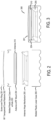
- FIG. 1 illustrates one embodiment of a portable satellite antenna system.
- the portable satellite antenna system comprises a container to house a satellite antenna.
- the container has a radio-frequency (RF) transparent lid 101 and a lower case 103.
- RF transparent lid 101 and lower case 103 house antenna 102.
- antenna 102 comprises a flat-panel electronically steered antenna. Examples of such antennas are described in more detail below. The embodiments disclosed herein are not limited to use with the antennas described below, and other types of antennas may be used.
- the systems include a flat-panel antenna that is not electronically steered.
- RF transparent lid 101 or portion thereof, comprises an RF transparent material through which antenna 102 is operable to transmit and receive satellite communications when lid 101 is on top of or otherwise covering the surface of antenna 102.
- antenna 102 is able to transmit and receive satellite communications through the RF transparent portion of lid 101 during closed-container operation when the container is closed.
- lid 101 operates as a radome of antenna 102.
- the tuning of the material is also a function of its thickness and the distance of lid 101 from the transmit and receive surface of antenna 102.
- the thickness of lid 101 and distance of lid 101 from the surface of antenna 102 is such that it doesn't impede transmit and receive satellite communications of antenna 102. Such communications are not impeded if signals at the antenna's designed frequency or frequency band of operation are minimally attenuated or reflected by lid 101.
- the distance between lid 101 and the surface of antenna 102 is dependent on the material used for the radome and the tuning.
- the distance between lid 101 and the surface of antenna 102 is between 1 ⁇ 4"-1/2" and is a function of radome tuning/thickness and could be greater.
- the design of lid 101 incorporates both RF and mechanical/environmental requirements.
- Several design approaches are available to the designer to address specific system requirements. For example, if the lid has minimal mechanical requirements, a very thin skin (e.g., ⁇ 0.05 wavelength) of thermoplastic material can be used, while if structural rigidity is required, a solid half wave wall design (wherein the dielectric thickness of the wall is 1 ⁇ 2 wavelength) or sandwich construction may be appropriate.
- a specific design necessarily includes consideration of material dielectric properties, design approach, and antenna RF requirements. Design selections inherently embody tradeoffs between these typically conflicting requirements.
- RF transparent lid 101 operates as the upper case that works with lower case 103 to form a closed container.
- the closed container is structurally sound such that it may be placed on any of its sides.
- RF transparent lid 101 comprises a material that is RF transparent and is structurally strong enough to support the container for transporting antenna 102.
- the material is also light-weight to enable the container with antenna 102 to be easily transported.
- the outer or externally exposed surface of lid 101 has a convex shape.
- the convex surface prevents liquids (e.g., rain water) from pooling on top of lid 101, which would cause attenuation in the transmit and receive satellite signals.
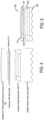
- RF mount 204 is coupled to an antenna hinge mechanism 205.
- antenna hinge mechanism 205 allows the antenna to be positioned (e.g., inclined) when the container is open and antenna 210 is exposed.
- Hinge mechanism 205 is coupled or otherwise attached to lower case 206. Note that in alternative embodiments, lower case 206 is a different material than upper case 203.
- the antenna is a rapidly deployable networking system.
- the rapidly deployable networking system supports personnel, organizations and agencies with establishment of, connectivity to and bridging of a broad range of terrestrial and on-orbit networks.
- the system supports traditional VSAT networks through the satellite terminal with the ability to connect to LEO and GEO satellite constellations.
- additional terrestrial and airborne network connections are created and bridges to enable full-spectrum communications in a deployed environment.
- the entire system is capable of operating as a self-contained and self-powered system (e.g., lithium ion batteries, solar panels. etc.) or may be connected to available power sources.
- Embodiments of the antenna include one or more of the following advantages.
- the antenna configuration enables a portable solution for communications on the pause (COTP) or communications on the move (COTM) operation without a custom mounting solution, designed to operate from within the container.
- the container is designed with D rings so that tie downs may be used to mount the antenna to a platform, such as, for example, a vehicle or vessel.
- Time from deployment to operations is approximately 5 minutes and typically does not require a subject matter expert. Average time for traditional VSATs from deployment to operations is approximately 90 minutes (minimum) and requires a SATCOM technician.
- the interconnected network architecture allows for communication from anywhere in the world to anywhere in the world.
- a disaster recovery individual in a disaster zone can communicate via push to talk radios to personnel within range of the radio as well as support personnel on a cellular telephone on another continent without changing devices or physically connecting to a different network. This reduces the handheld communications equipment personnel must carry but allows assured communication.
- the antenna includes a coarse alignment mechanism. Because of the accurate pointing, acquisition, and tracking capabilities of flat panel antenna, a precise alignment mechanism is not needed for the surface of the antenna. That is, embodiments of the container containing a flat panel antenna with electronic scanning, in conjunction with an RF-transparent material in the lid of the case, provide a unique capability to operate with the lid of the case on, with the case resting flat on the ground, thereby providing for inconspicuous use. Therefore, adversaries will not be able to see the antenna, or distinguish the case as a piece of satellite communications equipment. Imagery intelligence will only reveal a non-descript, black case.
- the case used to house the antenna has a thin profile, which is a distinct advantage over existing portable airtight, watertight temperature-controlled packaging and protective systems used for dish-type VSAT.
- the thin case profile and wheel assembly is non-obvious because it is enabled by the flat-panel antenna.
- the case, including the wheels, enables the antenna system to be easily roll through doorways and other narrow spaces.
- the techniques described above may be used with flat panel antennas. Embodiments of such flat panel antennas are disclosed.
- the flat panel antennas include one or more arrays of antenna elements on an antenna aperture.
- the antenna elements comprise liquid crystal cells.
- the flat panel antenna is a cylindrically fed antenna that includes matrix drive circuitry to uniquely address and drive each of the antenna elements that are not placed in rows and columns. In one embodiment, the elements are placed in rings.
- the antenna aperture having the one or more arrays of antenna elements is comprised of multiple segments coupled together. When coupled together, the combination of the segments form closed concentric rings of antenna elements. In one embodiment, the concentric rings are concentric with respect to the antenna feed.
- the flat panel antenna is part of a metamaterial antenna system.
- a metamaterial antenna system for communications satellite earth stations are described.
- the antenna system is a component or subsystem of a satellite earth station (ES) operating on a mobile platform (e.g., aeronautical, maritime, land, etc.) that operates using either Ka-band frequencies or Ku-band frequencies for civil commercial satellite communications.
- ES satellite earth station
- mobile platform e.g., aeronautical, maritime, land, etc.
- embodiments of the antenna system also can be used in earth stations that are not on mobile platforms (e.g., fixed or transportable earth stations).
- the antenna system uses surface scattering metamaterial technology to form and steer transmit and receive beams through separate antennas.
- the antenna systems are analog systems, in contrast to antenna systems that employ digital signal processing to electrically form and steer beams (such as phased array antennas).
- the antenna system is comprised of three functional subsystems: (1) a wave guiding structure consisting of a cylindrical wave feed architecture; (2) an array of wave scattering metamaterial unit cells that are part of antenna elements; and (3) a control structure to command formation of an adjustable radiation field (beam) from the metamaterial scattering elements using holographic principles.
- a wave guiding structure consisting of a cylindrical wave feed architecture
- an array of wave scattering metamaterial unit cells that are part of antenna elements
- a control structure to command formation of an adjustable radiation field (beam) from the metamaterial scattering elements using holographic principles.
- FIG. 6 illustrates the schematic of one embodiment of a cylindrically fed holographic radial aperture antenna.
- the antenna aperture has one or more arrays 601 of antenna elements 603 that are placed in concentric rings around an input feed 602 of the cylindrically fed antenna.
- antenna elements 603 are radio frequency (RF) resonators that radiate RF energy.
- antenna elements 603 comprise both Rx and Tx irises that are interleaved and distributed on the whole surface of the antenna aperture.
- Such Rx and Tx irises, or slots may be in groups of three or more sets where each set is for a separately and simultaneously controlled band. Examples of such antenna elements with irises are described in greater detail below. Note that the RF resonators described herein may be used in antennas that do not include a cylindrical feed.
- the antenna includes a coaxial feed that is used to provide a cylindrical wave feed via input feed 602.
- the cylindrical wave feed architecture feeds the antenna from a central point with an excitation that spreads outward in a cylindrical manner from the feed point. That is, a cylindrically fed antenna creates an outward travelling concentric feed wave. Even so, the shape of the cylindrical feed antenna around the cylindrical feed can be circular, square or any shape. In another embodiment, a cylindrically fed antenna creates an inward travelling feed wave. In such a case, the feed wave most naturally comes from a circular structure.
- antenna elements 603 comprise irises and the aperture antenna of Figure 6 is used to generate a main beam shaped by using excitation from a cylindrical feed wave for radiating irises through tunable liquid crystal (LC) material.
- the antenna can be excited to radiate a horizontally or vertically polarized electric field at desired scan angles.
- the antenna elements comprise a group of patch antennas.
- This group of patch antennas comprises an array of scattering metamaterial elements.
- each scattering element in the antenna system is part of a unit cell that consists of a lower conductor, a dielectric substrate and an upper conductor that embeds a complementary electric inductive-capacitive resonator ("complementary electric LC" or "CELC”) that is etched in or deposited onto the upper conductor.
- CELC complementary electric inductive-capacitive resonator
- LC in the context of CELC refers to inductance-capacitance, as opposed to liquid crystal.
- a liquid crystal is disposed in the gap around the scattering element. This LC is driven by the direct drive embodiments described above.
- liquid crystal is encapsulated in each unit cell and separates the lower conductor associated with a slot from an upper conductor associated with its patch.
- Liquid crystal has a permittivity that is a function of the orientation of the molecules comprising the liquid crystal, and the orientation of the molecules (and thus the permittivity) can be controlled by adjusting the bias voltage across the liquid crystal.
- the liquid crystal integrates an on/off switch for the transmission of energy from the guided wave to the CELC. When switched on, the CELC emits an electromagnetic wave like an electrically small dipole antenna. Note that the teachings herein are not limited to having a liquid crystal that operates in a binary fashion with respect to energy transmission.
- the feed geometry of this antenna system allows the antenna elements to be positioned at forty-five-degree (45°) angles to the vector of the wave in the wave feed. Note that other positions may be used (e.g., at 40° angles). This position of the elements enables control of the free space wave received by or transmitted/radiated from the elements.
- the antenna elements are arranged with an inter-element spacing that is less than a free-space wavelength of the operating frequency of the antenna. For example, if there are four scattering elements per wavelength, the elements in the 30 GHz transmit antenna will be approximately 2.5 mm (i.e., 1/4th the 10mm free-space wavelength of 30 GHz).
- the two sets of elements are perpendicular to each other and simultaneously have equal amplitude excitation if controlled to the same tuning state. Rotating them +/-45 degrees relative to the feed wave excitation achieves both desired features at once. Rotating one set 0 degrees and the other 90 degrees would achieve the perpendicular goal, but not the equal amplitude excitation goal. Note that 0 and 90 degrees may be used to achieve isolation when feeding the array of antenna elements in a single structure from two sides.
- the amount of radiated power from each unit cell is controlled by applying a voltage to the patch (potential across the LC channel) using a controller. Traces to each patch are used to provide the voltage to the patch antenna. The voltage is used to tune or detune the capacitance and thus the resonance frequency of individual elements to effectuate beam forming. The voltage required is dependent on the liquid crystal mixture being used.
- the voltage tuning characteristic of liquid crystal mixtures is mainly described by a threshold voltage at which the liquid crystal starts to be affected by the voltage and the saturation voltage, above which an increase of the voltage does not cause major tuning in liquid crystal. These two characteristic parameters can change for different liquid crystal mixtures.
- a matrix drive is used to apply voltage to the patches in order to drive each cell separately from all the other cells without having a separate connection for each cell (direct drive). Because of the high density of elements, the matrix drive is an efficient way to address each cell individually.
- the control structure for the antenna system has 2 main components: the antenna array controller, which includes drive electronics, for the antenna system, is below the wave scattering structure (of surface scattering antenna elements such as described herein), while the matrix drive switching array is interspersed throughout the radiating RF array in such a way as to not interfere with the radiation.
- the drive electronics for the antenna system comprise commercial off-the shelf LCD controls used in commercial television appliances that adjust the bias voltage for each scattering element by adjusting the amplitude or duty cycle of an AC bias signal to that element.
- the generation of a focused beam by the metamaterial array of elements can be explained by the phenomenon of constructive and destructive interference.
- Individual electromagnetic waves sum up (constructive interference) if they have the same phase when they meet in free space and waves cancel each other (destructive interference) if they are in opposite phase when they meet in free space.
- the slots in a slotted antenna are positioned so that each successive slot is positioned at a different distance from the excitation point of the guided wave, the scattered wave from that element will have a different phase than the scattered wave of the previous slot. If the slots are spaced one quarter of a guided wavelength apart, each slot will scatter a wave with a one fourth phase delay from the previous slot.
- a liquid crystal is injected in the gap around the scattering element.
- Liquid crystal is encapsulated in each unit cell and separates the lower conductor associated with a slot from an upper conductor associated with its patch.
- Liquid crystal has a permittivity that is a function of the orientation of the molecules comprising the liquid crystal, and the orientation of the molecules (and thus the permittivity) can be controlled by adjusting the bias voltage across the liquid crystal. Using this property, the liquid crystal acts as an on/off switch for the transmission of energy from the guided wave to the CELC. When switched on, the CELC emits an electromagnetic wave like an electrically small dipole antenna.
- Controlling the thickness of the LC increases the beam switching speed.
- a fifty percent (50%) reduction in the gap between the lower and the upper conductor results in a fourfold increase in speed.
- the thickness of the liquid crystal results in a beam switching speed of approximately fourteen milliseconds (14ms).
- the LC is doped in a manner well-known in the art to improve responsiveness so that a seven millisecond (7ms) requirement can be met.
- the CELC element is responsive to a magnetic field that is applied parallel to the plane of the CELC element and perpendicular to the CELC gap complement.
- a voltage is applied to the liquid crystal in the metamaterial scattering unit cell, the magnetic field component of the guided wave induces a magnetic excitation of the CELC, which, in turn, produces an electromagnetic wave in the same frequency as the guided wave.
- the phase of the electromagnetic wave generated by a single CELC can be selected by the position of the CELC on the vector of the guided wave.
- Each cell generates a wave in phase with the guided wave parallel to the CELC. Because the CELCs are smaller than the wave length, the output wave has the same phase as the phase of the guided wave as it passes beneath the CELC.
- the cylindrical feed geometry of this antenna system allows the CELC elements to be positioned at forty-five-degree (45°) angles to the vector of the wave in the wave feed. This position of the elements enables control of the polarization of the free space wave generated from or received by the elements.
- the CELCs are arranged with an inter-element spacing that is less than a free-space wavelength of the operating frequency of the antenna. For example, if there are four scattering elements per wavelength, the elements in the 30 GHz transmit antenna will be approximately 2.5 mm (i.e., 1/4th the 10mm free-space wavelength of 30 GHz).
- the CELCs are implemented with patch antennas that include a patch co-located over a slot with liquid crystal between the two.
- the metamaterial antenna acts like a slotted (scattering) wave guide. With a slotted wave guide, the phase of the output wave depends on the location of the slot in relation to the guided wave.
- the antenna elements are placed on the cylindrical feed antenna aperture in a way that allows for a systematic matrix drive circuit.
- the placement of the cells includes placement of the transistors for the matrix drive.
- Figure 12 illustrates one embodiment of the placement of matrix drive circuitry with respect to antenna elements.
- row controller 1701 is coupled to transistors 1711 and 1712, via row select signals Row1 and Row2, respectively, and column controller 1702 is coupled to transistors 1711 and 1712 via column select signal Column1.
- Transistor 1711 is also coupled to antenna element 1721 via connection to patch 1731, while transistor 1712 is coupled to antenna element 1722 via connection to patch 1732.
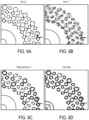
- the cells are placed on concentric rings and each of the cells is connected to a transistor that is placed beside the cell and acts as a switch to drive each cell separately.
- the matrix drive circuitry is built in order to connect every transistor with a unique address as the matrix drive approach requires. Because the matrix drive circuit is built by row and column traces (similar to LCDs) but the cells are placed on rings, there is no systematic way to assign a unique address to each transistor. This mapping problem results in very complex circuitry to cover all the transistors and leads to a significant increase in the number of physical traces to accomplish the routing. Because of the high density of cells, those traces disturb the RF performance of the antenna due to coupling effect. Also, due to the complexity of traces and high packing density, the routing of the traces cannot be accomplished by commercially available layout tools.
- the matrix drive circuitry is predefined before the cells and transistors are placed. This ensures a minimum number of traces that are necessary to drive all the cells, each with a unique address. This strategy reduces the complexity of the drive circuitry and simplifies the routing, which subsequently improves the RF performance of the antenna.
- the cells are placed on a regular rectangular grid composed of rows and columns that describe the unique address of each cell.
- the cells are grouped and transformed to concentric circles while maintaining their address and connection to the rows and columns as defined in the first step.
- a goal of this transformation is not only to put the cells on rings but also to keep the distance between cells and the distance between rings constant over the entire aperture. In order to accomplish this goal, there are several ways to group the cells.
- a TFT package is used to enable placement and unique addressing in the matrix drive.
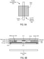
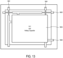
- Figure 13 illustrates one embodiment of a TFT package. Referring to Figure 13 , a TFT and a hold capacitor 1803 is shown with input and output ports. There are two input ports connected to traces 1801 and two output ports connected to traces 1802 to connect the TFTs together using the rows and columns.
- the row and column traces cross in 90° angles to reduce, and potentially minimize, the coupling between the row and column traces.
- the row and column traces are on different layers.
- FIG. 14 is a block diagram of an embodiment of a communication system having simultaneous transmit and receive paths. While only one transmit path and one receive path are shown, the communication system may include more than one transmit path and/or more than one receive path.
- antenna 1401 includes two spatially interleaved antenna arrays operable independently to transmit and receive simultaneously at different frequencies as described above.
- antenna 1401 is coupled to diplexer 1445.
- the coupling may be by one or more feeding networks.
- diplexer 1445 combines the two signals and the connection between antenna 1401 and diplexer 1445 is a single broad-band feeding network that can carry both frequencies.
- Diplexer 1445 is coupled to a low noise block down converter (LNBs) 1427, which performs a noise filtering function and a down conversion and amplification function in a manner well-known in the art.
- LNB 1427 is in an out-door unit (ODU).
- ODU out-door unit
- LNB 1427 is integrated into the antenna apparatus.
- LNB 1427 is coupled to a modem 1460, which is coupled to computing system 1440 (e.g., a computer system, modem, etc.).
- Modem 1460 includes an analog-to-digital converter (ADC) 1422, which is coupled to LNB 1427, to convert the received signal output from diplexer 1445 into digital format. Once converted to digital format, the signal is demodulated by demodulator 1423 and decoded by decoder 1424 to obtain the encoded data on the received wave. The decoded data is then sent to controller 1425, which sends it to computing system 1440.
- ADC analog-to-digital converter
- Modem 1460 also includes an encoder 1430 that encodes data to be transmitted from computing system 1440.
- the encoded data is modulated by modulator 1431 and then converted to analog by digital-to-analog converter (DAC) 1432.
- DAC digital-to-analog converter
- the analog signal is then filtered by a BUC (up-convert and high pass amplifier) 1433 and provided to one port of diplexer 1445.
- BUC 1433 is in an out-door unit (ODU).
- Diplexer 1445 operating in a manner well-known in the art provides the transmit signal to antenna 1401 for transmission.
- Controller 1450 controls antenna 1401, including the two arrays of antenna elements on the single combined physical aperture.
- the communication system would be modified to include the combiner/arbiter described above. In such a case, the combiner/arbiter after the modem but before the BUC and LNB.
- the full duplex communication system shown in Figure 14 has a number of applications, including but not limited to, internet communication, vehicle communication (including software updating), etc.
- Example 1 is a portable satellite antenna apparatus comprising a flat panel antenna and a container to house the antenna, the container having at least one radio-frequency (RF) transparent material through which the antenna is operable to transmit and receive satellite communications.
- RF radio-frequency
- Example 2 is the antenna apparatus of example 1 that may optionally include that the at least one RF transparent material comprises a lid of the container.
- Example 3 is the antenna apparatus of example 2 that may optionally include that the lid is operable as a radome of the antenna.
- Example 4 is the antenna apparatus of example 1 that may optionally include that the at least one RF transparent material comprises plastic or fiberglass.
- Example 5 is the antenna apparatus of example 1 that may optionally include that the at least one RF transparent material is tuned to frequencies at which the antenna is designed to operate.
- Example 6 is the antenna apparatus of example 1 that may optionally include that the at least one RF transparent material has a convex shape with respect to a surface of the antenna through which the antenna transmits and receives the satellite communications.
- Example 7 is the antenna apparatus of example 1 that may optionally include that an externally exposed portion of the at least one RF transparent material has a hydrophobic coating.
- Example 8 is the antenna apparatus of example 1 that may optionally include that the antenna is operable to transmit and receive satellite communications through the at least one RF transparent material during closed-container operation when the container is closed.
- Example 9 is a portable satellite antenna apparatus comprising a flat panel antenna and a container to house the antenna, the container having at least one RF transparent lid through which the antenna is operable to transmit and receive satellite communications, wherein the lid comprises a material that is a predetermined distance from the antenna surface and tuned to frequencies at which the antenna is designed to operate, wherein the antenna is operable to transmit and receive satellite communications through the at least one RF transparent lid for closed-container operation when the container is closed.
Landscapes
- Variable-Direction Aerials And Aerial Arrays (AREA)
Claims (13)
- Eine tragbare Satellitenantennenvorrichtung, umfassend:eine Flachantenne (102); undein Gehäuse (110), um die Antenne (102) aufzunehmen, wobei das Gehäuse (110) mindestens ein radiofrequenz- (RF) transparentes Material aufweist, durch das die Antenne (102) zum Senden und Empfangen von Satellitenkommunikationen betreibbar ist, wobei das mindestens eine RF-transparente Material einen Deckel (101) des Gehäuses (110) aufweist, der sich in einem Abstand von der Flachantenne befindet und oberhalb der Antenne (102) abnehmbar ist, um das Gehäuse (110) für einen Betrieb zu öffnen, bei dem die Antenne betreibbar ist, Satellitenkommunikationen zu senden und empfangen, wenn das Gehäuse offen ist, wobei die Antenne (102) betreibbar ist, Satellitenkommunikationen durch das mindestens eine RF-transparente Material während des Geschlossenes-Gehäuse-Betriebs zu senden und empfangen, wenn das Gehäuse (110) geschlossen ist.
- Die Vorrichtung gemäß Anspruch 1, wobei das mindestens eine RF-transparente Material Kunststoff oder Glasfaser aufweist.
- Die Vorrichtung gemäß einem der Ansprüche 1 bis 2, wobei das mindestens eine RF-transparente Material auf Frequenzen abgestimmt ist, auf deren Betrieb die Antenne (102) ausgelegt ist.
- Die Vorrichtung gemäß einem der Ansprüche 1 bis 3, wobei das mindestens eine RF-transparente Material eine konvexe Form in Bezug auf eine Oberfläche der Antenne (102) aufweist, durch die die Antenne (102) die Satellitenkommunikationen sendet und empfängt.
- Die Vorrichtung gemäß einem der Ansprüche 1 bis 4, wobei ein nach außen freiliegender Teil des mindestens einen RF-transparenten Materials eine hydrophobe Beschichtung aufweist.
- Die Vorrichtung gemäß einem der Ansprüche 1 bis 5, wobei der Deckel (101) ein Material aufweist, das einen vorbestimmten Abstand von der Oberfläche der Antenne (102) hat, wenn das Gehäuse geschlossen ist, und auf Frequenzen abgestimmt ist, auf die der Betrieb der Antenne (102) ausgelegt ist, wobei die Antenne (102) betreibbar ist, um die Satellitenkommunikationen durch den mindestens einen RF-transparenten Deckel (101) für den Geschlossenes-Gehäuse-Betrieb zu senden und empfangen, wenn das Gehäuse (110) geschlossen ist.
- Die Vorrichtung gemäß Anspruch 6, wobei das mindestens eine RF-transparente Material Kunststoff oder Glasfaser aufweist.
- Die Vorrichtung gemäß einem der Ansprüche 6 oder 7, wobei das mindestens eine RF-transparente Material eine konvexe Form in Bezug auf eine Oberfläche der Antenne (102) aufweist, durch die die Antenne (102) die Satellitenkommunikationen sendet und empfängt.
- Die Vorrichtung gemäß einem der Ansprüche 6 bis 8, wobei ein nach außen freiliegender Teil des mindestens einen RF-transparenten Materials eine hydrophobe Beschichtung aufweist.
- Die Vorrichtung gemäß einem der Ansprüche 6 bis 9, wobei das Material eine Dicke aufweist, die eine schützende Hülle und eine Strukturunterstützung für das Gehäuse (110) als Transportkoffer bietet, während es die RF-Übertragung nicht behindert.
- Die Vorrichtung gemäß einem der Ansprüche 6 bis 10, weiter aufweisend ein schnell einsetzbares und eigenständiges Netzwerksystem.
- Die Vorrichtung gemäß Anspruch 1, wobei der Deckel (101) von der Antenne (102) so beabstandet ist, dass mittels des Deckels (101) verursachte Deckelreflexionen während des Geschlossenes-Gehäuse-Betriebs nicht destruktiv mit den Feldern in der Antenne (102) wechselwirken.
- Die Vorrichtung gemäß Anspruch 1, wobei der Deckel (101) von der Antenne (102) um 1,0 Wellenlängen beabstandet ist, so dass mittels des Deckels (101) verursachte Deckelreflexionen während des Geschlossenes-Gehäuse-Betriebs mit den Feldern in der Antenne (102) konstruktiv wechselwirken.
Applications Claiming Priority (2)
| Application Number | Priority Date | Filing Date | Title |
|---|---|---|---|
| US201862641120P | 2018-03-09 | 2018-03-09 | |
| US16/295,204 US11063362B2 (en) | 2018-03-09 | 2019-03-07 | Portable flat-panel satellite antenna |
Publications (2)
| Publication Number | Publication Date |
|---|---|
| EP3537538A1 EP3537538A1 (de) | 2019-09-11 |
| EP3537538B1 true EP3537538B1 (de) | 2025-07-02 |
Family
ID=65763325
Family Applications (1)
| Application Number | Title | Priority Date | Filing Date |
|---|---|---|---|
| EP19161828.9A Active EP3537538B1 (de) | 2018-03-09 | 2019-03-11 | Tragbare flachbildschirm-satellitenantenne |
Country Status (3)
| Country | Link |
|---|---|
| US (1) | US11063362B2 (de) |
| EP (1) | EP3537538B1 (de) |
| ES (1) | ES3036707T3 (de) |
Families Citing this family (7)
| Publication number | Priority date | Publication date | Assignee | Title |
|---|---|---|---|---|
| US10461421B1 (en) * | 2019-05-07 | 2019-10-29 | Bao Tran | Cellular system |
| US11012147B1 (en) * | 2020-01-16 | 2021-05-18 | M2SL Corporation | Multi-mode communication adapter system with smartphone protector mechanism and method of operation thereof |
| US11223127B2 (en) | 2020-01-22 | 2022-01-11 | UTVATE Corporation | Reduced scan loss antenna systems for communicating with satellites at low elevation angles |
| US12355158B1 (en) | 2021-07-08 | 2025-07-08 | Lockheed Martin Corporation | Vivaldi antenna structures with concurrent transmit and receive |
| US12148999B1 (en) | 2021-07-08 | 2024-11-19 | Lockheed Martin Corporation | Multimode vivaldi antenna structures |
| US11936112B1 (en) | 2022-05-05 | 2024-03-19 | Lockheed Martin Corporation | Aperture antenna structures with concurrent transmit and receive |
| US12284025B2 (en) | 2022-05-11 | 2025-04-22 | Bao Tran | Mobile satellite communication system |
Family Cites Families (5)
| Publication number | Priority date | Publication date | Assignee | Title |
|---|---|---|---|---|
| US9637248B2 (en) * | 2013-03-15 | 2017-05-02 | The Boeing Company | Component deployment system |
| US9887456B2 (en) | 2014-02-19 | 2018-02-06 | Kymeta Corporation | Dynamic polarization and coupling control from a steerable cylindrically fed holographic antenna |
| US9722305B2 (en) * | 2015-08-20 | 2017-08-01 | Google Inc. | Balanced multi-layer printed circuit board for phased-array antenna |
| US20170187101A1 (en) | 2015-12-23 | 2017-06-29 | Tom Freeman | Device system and method for providing mobile satellite communication |
| US10535919B2 (en) * | 2016-05-24 | 2020-01-14 | Kymeta Corporation | Low-profile communication terminal and method of providing same |
-
2019
- 2019-03-07 US US16/295,204 patent/US11063362B2/en active Active
- 2019-03-11 ES ES19161828T patent/ES3036707T3/es active Active
- 2019-03-11 EP EP19161828.9A patent/EP3537538B1/de active Active
Also Published As
| Publication number | Publication date |
|---|---|
| US20190280387A1 (en) | 2019-09-12 |
| ES3036707T3 (en) | 2025-09-23 |
| US11063362B2 (en) | 2021-07-13 |
| EP3537538A1 (de) | 2019-09-11 |
Similar Documents
| Publication | Publication Date | Title |
|---|---|---|
| US12542354B1 (en) | Broad tunable bandwidth radial line slot antenna | |
| US20220328962A1 (en) | Impedance matching for an aperture antenna | |
| US10886635B2 (en) | Combined antenna apertures allowing simultaneous multiple antenna functionality | |
| US11063362B2 (en) | Portable flat-panel satellite antenna | |
| US11700054B2 (en) | Modular metasurface antenna with high instantaneous bandwidth | |
| US11705634B2 (en) | Single-layer wide angle impedance matching (WAIM) | |
| US11601192B2 (en) | Multi-beam metasurface antenna | |
| US20190097299A1 (en) | Integrated transceiver for antenna systems | |
| US11811489B2 (en) | Adaptive and learning motion mitigation for uplink power control | |
| US11799211B2 (en) | Multiband guiding structures for antennas | |
| US20200328515A1 (en) | Non-circular center-fed antenna and method for using the same | |
| US11855347B2 (en) | Radial feed segmentation using wedge plates radial waveguide |
Legal Events
| Date | Code | Title | Description |
|---|---|---|---|
| PUAI | Public reference made under article 153(3) epc to a published international application that has entered the european phase |
Free format text: ORIGINAL CODE: 0009012 |
|
| STAA | Information on the status of an ep patent application or granted ep patent |
Free format text: STATUS: THE APPLICATION HAS BEEN PUBLISHED |
|
| AK | Designated contracting states |
Kind code of ref document: A1 Designated state(s): AL AT BE BG CH CY CZ DE DK EE ES FI FR GB GR HR HU IE IS IT LI LT LU LV MC MK MT NL NO PL PT RO RS SE SI SK SM TR |
|
| AX | Request for extension of the european patent |
Extension state: BA ME |
|
| STAA | Information on the status of an ep patent application or granted ep patent |
Free format text: STATUS: REQUEST FOR EXAMINATION WAS MADE |
|
| 17P | Request for examination filed |
Effective date: 20200305 |
|
| RBV | Designated contracting states (corrected) |
Designated state(s): AL AT BE BG CH CY CZ DE DK EE ES FI FR GB GR HR HU IE IS IT LI LT LU LV MC MK MT NL NO PL PT RO RS SE SI SK SM TR |
|
| STAA | Information on the status of an ep patent application or granted ep patent |
Free format text: STATUS: EXAMINATION IS IN PROGRESS |
|
| 17Q | First examination report despatched |
Effective date: 20210806 |
|
| GRAP | Despatch of communication of intention to grant a patent |
Free format text: ORIGINAL CODE: EPIDOSNIGR1 |
|
| STAA | Information on the status of an ep patent application or granted ep patent |
Free format text: STATUS: GRANT OF PATENT IS INTENDED |
|
| INTG | Intention to grant announced |
Effective date: 20250121 |
|
| GRAS | Grant fee paid |
Free format text: ORIGINAL CODE: EPIDOSNIGR3 |
|
| GRAA | (expected) grant |
Free format text: ORIGINAL CODE: 0009210 |
|
| STAA | Information on the status of an ep patent application or granted ep patent |
Free format text: STATUS: THE PATENT HAS BEEN GRANTED |
|
| AK | Designated contracting states |
Kind code of ref document: B1 Designated state(s): AL AT BE BG CH CY CZ DE DK EE ES FI FR GB GR HR HU IE IS IT LI LT LU LV MC MK MT NL NO PL PT RO RS SE SI SK SM TR |
|
| REG | Reference to a national code |
Ref country code: GB Ref legal event code: FG4D |
|
| REG | Reference to a national code |
Ref country code: CH Ref legal event code: EP |
|
| REG | Reference to a national code |
Ref country code: DE Ref legal event code: R096 Ref document number: 602019071845 Country of ref document: DE |
|
| REG | Reference to a national code |
Ref country code: IE Ref legal event code: FG4D |
|
| REG | Reference to a national code |
Ref country code: ES Ref legal event code: FG2A Ref document number: 3036707 Country of ref document: ES Kind code of ref document: T3 Effective date: 20250923 |
|
| REG | Reference to a national code |
Ref country code: NL Ref legal event code: MP Effective date: 20250702 |
|
| PG25 | Lapsed in a contracting state [announced via postgrant information from national office to epo] |
Ref country code: PT Free format text: LAPSE BECAUSE OF FAILURE TO SUBMIT A TRANSLATION OF THE DESCRIPTION OR TO PAY THE FEE WITHIN THE PRESCRIBED TIME-LIMIT Effective date: 20251103 |
|
| PG25 | Lapsed in a contracting state [announced via postgrant information from national office to epo] |
Ref country code: NL Free format text: LAPSE BECAUSE OF FAILURE TO SUBMIT A TRANSLATION OF THE DESCRIPTION OR TO PAY THE FEE WITHIN THE PRESCRIBED TIME-LIMIT Effective date: 20250702 |
|
| REG | Reference to a national code |
Ref country code: AT Ref legal event code: MK05 Ref document number: 1810358 Country of ref document: AT Kind code of ref document: T Effective date: 20250702 |
|
| PG25 | Lapsed in a contracting state [announced via postgrant information from national office to epo] |
Ref country code: IS Free format text: LAPSE BECAUSE OF FAILURE TO SUBMIT A TRANSLATION OF THE DESCRIPTION OR TO PAY THE FEE WITHIN THE PRESCRIBED TIME-LIMIT Effective date: 20251102 |
|
| PG25 | Lapsed in a contracting state [announced via postgrant information from national office to epo] |
Ref country code: NO Free format text: LAPSE BECAUSE OF FAILURE TO SUBMIT A TRANSLATION OF THE DESCRIPTION OR TO PAY THE FEE WITHIN THE PRESCRIBED TIME-LIMIT Effective date: 20251002 |
|
| REG | Reference to a national code |
Ref country code: LT Ref legal event code: MG9D |
|
| PG25 | Lapsed in a contracting state [announced via postgrant information from national office to epo] |
Ref country code: AT Free format text: LAPSE BECAUSE OF FAILURE TO SUBMIT A TRANSLATION OF THE DESCRIPTION OR TO PAY THE FEE WITHIN THE PRESCRIBED TIME-LIMIT Effective date: 20250702 |
|
| PG25 | Lapsed in a contracting state [announced via postgrant information from national office to epo] |
Ref country code: FI Free format text: LAPSE BECAUSE OF FAILURE TO SUBMIT A TRANSLATION OF THE DESCRIPTION OR TO PAY THE FEE WITHIN THE PRESCRIBED TIME-LIMIT Effective date: 20250702 |
|
| PG25 | Lapsed in a contracting state [announced via postgrant information from national office to epo] |
Ref country code: HR Free format text: LAPSE BECAUSE OF FAILURE TO SUBMIT A TRANSLATION OF THE DESCRIPTION OR TO PAY THE FEE WITHIN THE PRESCRIBED TIME-LIMIT Effective date: 20250702 |
|
| PG25 | Lapsed in a contracting state [announced via postgrant information from national office to epo] |
Ref country code: GR Free format text: LAPSE BECAUSE OF FAILURE TO SUBMIT A TRANSLATION OF THE DESCRIPTION OR TO PAY THE FEE WITHIN THE PRESCRIBED TIME-LIMIT Effective date: 20251003 |
|
| PG25 | Lapsed in a contracting state [announced via postgrant information from national office to epo] |
Ref country code: CZ Free format text: LAPSE BECAUSE OF FAILURE TO SUBMIT A TRANSLATION OF THE DESCRIPTION OR TO PAY THE FEE WITHIN THE PRESCRIBED TIME-LIMIT Effective date: 20250702 Ref country code: SE Free format text: LAPSE BECAUSE OF FAILURE TO SUBMIT A TRANSLATION OF THE DESCRIPTION OR TO PAY THE FEE WITHIN THE PRESCRIBED TIME-LIMIT Effective date: 20250702 |
|
| PG25 | Lapsed in a contracting state [announced via postgrant information from national office to epo] |
Ref country code: LV Free format text: LAPSE BECAUSE OF FAILURE TO SUBMIT A TRANSLATION OF THE DESCRIPTION OR TO PAY THE FEE WITHIN THE PRESCRIBED TIME-LIMIT Effective date: 20250702 |
|
| PG25 | Lapsed in a contracting state [announced via postgrant information from national office to epo] |
Ref country code: PL Free format text: LAPSE BECAUSE OF FAILURE TO SUBMIT A TRANSLATION OF THE DESCRIPTION OR TO PAY THE FEE WITHIN THE PRESCRIBED TIME-LIMIT Effective date: 20250702 Ref country code: BG Free format text: LAPSE BECAUSE OF FAILURE TO SUBMIT A TRANSLATION OF THE DESCRIPTION OR TO PAY THE FEE WITHIN THE PRESCRIBED TIME-LIMIT Effective date: 20250702 |
|
| PG25 | Lapsed in a contracting state [announced via postgrant information from national office to epo] |
Ref country code: RS Free format text: LAPSE BECAUSE OF FAILURE TO SUBMIT A TRANSLATION OF THE DESCRIPTION OR TO PAY THE FEE WITHIN THE PRESCRIBED TIME-LIMIT Effective date: 20251002 |
|
| PG25 | Lapsed in a contracting state [announced via postgrant information from national office to epo] |
Ref country code: SM Free format text: LAPSE BECAUSE OF FAILURE TO SUBMIT A TRANSLATION OF THE DESCRIPTION OR TO PAY THE FEE WITHIN THE PRESCRIBED TIME-LIMIT Effective date: 20250702 |
|
| PGFP | Annual fee paid to national office [announced via postgrant information from national office to epo] |
Ref country code: GB Payment date: 20260327 Year of fee payment: 8 |
|
| PG25 | Lapsed in a contracting state [announced via postgrant information from national office to epo] |
Ref country code: DK Free format text: LAPSE BECAUSE OF FAILURE TO SUBMIT A TRANSLATION OF THE DESCRIPTION OR TO PAY THE FEE WITHIN THE PRESCRIBED TIME-LIMIT Effective date: 20250702 |
|
| PGFP | Annual fee paid to national office [announced via postgrant information from national office to epo] |
Ref country code: DE Payment date: 20260327 Year of fee payment: 8 |
|
| PGFP | Annual fee paid to national office [announced via postgrant information from national office to epo] |
Ref country code: IT Payment date: 20260319 Year of fee payment: 8 |
|
| PGFP | Annual fee paid to national office [announced via postgrant information from national office to epo] |
Ref country code: FR Payment date: 20260325 Year of fee payment: 8 |
|
| PG25 | Lapsed in a contracting state [announced via postgrant information from national office to epo] |
Ref country code: SK Free format text: LAPSE BECAUSE OF FAILURE TO SUBMIT A TRANSLATION OF THE DESCRIPTION OR TO PAY THE FEE WITHIN THE PRESCRIBED TIME-LIMIT Effective date: 20250702 Ref country code: EE Free format text: LAPSE BECAUSE OF FAILURE TO SUBMIT A TRANSLATION OF THE DESCRIPTION OR TO PAY THE FEE WITHIN THE PRESCRIBED TIME-LIMIT Effective date: 20250702 |
|
| PLBE | No opposition filed within time limit |
Free format text: ORIGINAL CODE: 0009261 |
|
| STAA | Information on the status of an ep patent application or granted ep patent |
Free format text: STATUS: NO OPPOSITION FILED WITHIN TIME LIMIT |