EP3537275A1 - Information display device, information display method, and program - Google Patents
Information display device, information display method, and program Download PDFInfo
- Publication number
- EP3537275A1 EP3537275A1 EP17867810.8A EP17867810A EP3537275A1 EP 3537275 A1 EP3537275 A1 EP 3537275A1 EP 17867810 A EP17867810 A EP 17867810A EP 3537275 A1 EP3537275 A1 EP 3537275A1
- Authority
- EP
- European Patent Office
- Prior art keywords
- sub
- widgets
- widget
- condition
- information
- Prior art date
- Legal status (The legal status is an assumption and is not a legal conclusion. Google has not performed a legal analysis and makes no representation as to the accuracy of the status listed.)
- Granted
Links
Images



Classifications
-
- G—PHYSICS
- G06—COMPUTING OR CALCULATING; COUNTING
- G06F—ELECTRIC DIGITAL DATA PROCESSING
- G06F3/00—Input arrangements for transferring data to be processed into a form capable of being handled by the computer; Output arrangements for transferring data from processing unit to output unit, e.g. interface arrangements
- G06F3/01—Input arrangements or combined input and output arrangements for interaction between user and computer
- G06F3/048—Interaction techniques based on graphical user interfaces [GUI]
- G06F3/0484—Interaction techniques based on graphical user interfaces [GUI] for the control of specific functions or operations, e.g. selecting or manipulating an object, an image or a displayed text element, setting a parameter value or selecting a range
- G06F3/04847—Interaction techniques to control parameter settings, e.g. interaction with sliders or dials
-
- G—PHYSICS
- G06—COMPUTING OR CALCULATING; COUNTING
- G06F—ELECTRIC DIGITAL DATA PROCESSING
- G06F11/00—Error detection; Error correction; Monitoring
- G06F11/30—Monitoring
- G06F11/32—Monitoring with visual or acoustical indication of the functioning of the machine
-
- G—PHYSICS
- G06—COMPUTING OR CALCULATING; COUNTING
- G06F—ELECTRIC DIGITAL DATA PROCESSING
- G06F3/00—Input arrangements for transferring data to be processed into a form capable of being handled by the computer; Output arrangements for transferring data from processing unit to output unit, e.g. interface arrangements
- G06F3/01—Input arrangements or combined input and output arrangements for interaction between user and computer
- G06F3/048—Interaction techniques based on graphical user interfaces [GUI]
- G06F3/0481—Interaction techniques based on graphical user interfaces [GUI] based on specific properties of the displayed interaction object or a metaphor-based environment, e.g. interaction with desktop elements like windows or icons, or assisted by a cursor's changing behaviour or appearance
-
- G—PHYSICS
- G06—COMPUTING OR CALCULATING; COUNTING
- G06F—ELECTRIC DIGITAL DATA PROCESSING
- G06F3/00—Input arrangements for transferring data to be processed into a form capable of being handled by the computer; Output arrangements for transferring data from processing unit to output unit, e.g. interface arrangements
- G06F3/01—Input arrangements or combined input and output arrangements for interaction between user and computer
- G06F3/048—Interaction techniques based on graphical user interfaces [GUI]
- G06F3/0481—Interaction techniques based on graphical user interfaces [GUI] based on specific properties of the displayed interaction object or a metaphor-based environment, e.g. interaction with desktop elements like windows or icons, or assisted by a cursor's changing behaviour or appearance
- G06F3/04817—Interaction techniques based on graphical user interfaces [GUI] based on specific properties of the displayed interaction object or a metaphor-based environment, e.g. interaction with desktop elements like windows or icons, or assisted by a cursor's changing behaviour or appearance using icons
-
- G—PHYSICS
- G06—COMPUTING OR CALCULATING; COUNTING
- G06F—ELECTRIC DIGITAL DATA PROCESSING
- G06F3/00—Input arrangements for transferring data to be processed into a form capable of being handled by the computer; Output arrangements for transferring data from processing unit to output unit, e.g. interface arrangements
- G06F3/01—Input arrangements or combined input and output arrangements for interaction between user and computer
- G06F3/048—Interaction techniques based on graphical user interfaces [GUI]
- G06F3/0484—Interaction techniques based on graphical user interfaces [GUI] for the control of specific functions or operations, e.g. selecting or manipulating an object, an image or a displayed text element, setting a parameter value or selecting a range
- G06F3/0486—Drag-and-drop
-
- H—ELECTRICITY
- H04—ELECTRIC COMMUNICATION TECHNIQUE
- H04R—LOUDSPEAKERS, MICROPHONES, GRAMOPHONE PICK-UPS OR LIKE ACOUSTIC ELECTROMECHANICAL TRANSDUCERS; ELECTRIC HEARING AIDS; PUBLIC ADDRESS SYSTEMS
- H04R3/00—Circuits for transducers
-
- G—PHYSICS
- G06—COMPUTING OR CALCULATING; COUNTING
- G06F—ELECTRIC DIGITAL DATA PROCESSING
- G06F2201/00—Indexing scheme relating to error detection, to error correction, and to monitoring
- G06F2201/81—Threshold
Definitions
- the present invention in some embodiments thereof, relates to an information display apparatus, an information display method and a program that display information.
- An application program described in Non Patent Literature 1 has a function to perform a remote control and remote monitoring of a plurality of amplifiers.
- the application program accepts, for example, a setting of a threshold value for a temperature of a heat sink. With the application program, a warning is emitted when the temperature of the heat sink exceeds the threshold value.
- Non Patent Literature 1 Network Amp Manager, [online], [Searched on Sept. 30, 2016], Internet ⁇ URL:http//www.yamahaproaudio.com/japan/ja/products/perip herals/applications/networkampmanager/features.jsp>
- Non Patent Literature 1 the application program described in Non Patent Literature 1 is the one that performs individual management of a plurality of devices, and thus has been unable to perform management of as far as the entire system. As the number of devices within a system increases, the number of objects to manage increases; then, it becomes difficult to perform management of the entire system.
- the present invention in some embodiments thereof, is directed to providing an information display apparatus, an information display method and a program that are capable of performing management of an entire system.
- An information display apparatus includes a display portion and a control portion.
- the display portion displays widgets that include a main widget and a plurality of sub-widgets that indicate a state of a device or a state of a function installed on the device.
- the control portion executes: a process of placing a plurality of sub-widgets against the main widget; a process of setting the device or the function that is associated with each of the plurality of sub-widgets; a process of setting a condition for the device or a condition for the function that is associated with each of the plurality of sub-widgets; and a process of setting a relationship between conditions set for the plurality of sub-widgets and a condition set for the main widget.
- the information display apparatus is capable of performing management of an entire system.
- An information display apparatus sets a main widget that integrates a plurality of sub-widgets. Also, the information display apparatus sets a condition for each sub-widget, and sets a relationship between conditions for the sub-widget and the main widget. Thus, by performing management of the main widget, the user can perform management of states of a plurality of devices or functions that are allocated to a plurality of sub-widgets.
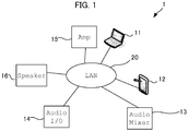
- Fig. 1 is a block diagram showing a configuration of a sound system.
- the sound system includes a laptop PC 11, a tablet PC 12, an audio mixer 13, an audio I/O unit 14, an amplifier 15, a speaker 16 and a LAN (Local Area Network) 20.
- the laptop PC 11, the tablet PC 12, the audio mixer 13, the audio I/O unit 14, the amplifier 15 and the speaker 16 are connected to each other through the LAN 20.
- connection mode for each device is not limited to a network connection through a LAN.
- each device may be connected through a MIDI (Musical Instrument Digital Interface).
- MIDI Musical Instrument Digital Interface
- the laptop PC 11 and the tablet PC 12 are respectively examples of the information display apparatus of the present invention, and are general purpose computers (information processing devices).
- Fig. 2 is a block diagram showing a configuration of the PC 11.
- the laptop PC 11 includes a display 101, a user interface (I/F) 102, a CPU 103, a flash ROM 104, a RAM 105 and a network interface (I/F) 106. These components are connected to a bus 151.
- the tablet PC 12 also has a configuration similar to that of the laptop PC 11.
- the display 101 consists of, for example, a LCD (Liquid Crystal Display), and displays various information.
- the user I/F 102 consists of, for example, a mouse, a keyboard, a touch panel and/or the like, and receives user's operation.
- the CPU 103 corresponds to a control portion, an information obtaining portion and so forth of the present invention.
- the CPU 103 reads out a program that is stored in the flash ROM 104, which is a storage medium, into the RAM 105 and realizes a predetermined function.
- the CPU 103 realizes a GUI by causing the display 101 to display an image of an operation portion (receiving portion) for receiving a user's operation and then by receiving, through the user I/F 102, a selection operation or the like to an image of the operation portion.
- the program is not necessarily stored in the flash ROM 104 in the own apparatus, but may be stored in a storage medium in an external device such as a server or the like, as is well-known. In such a case, the CPU 103 may each time read out the program from the server into the RAM 105 to execute.
- Fig. 3 is an example of a GUI displayed on the display 101. With the GUI shown in this example, the user performs operations such as placement of widgets, setting of devices or functions that are to be associated with the widgets, and so forth.
- a widget is an element to constitute a GUI.
- an alert indicator 85, an ON/OFF button 86, a slider 87, a knob 88 and a meter 89 are displayed.
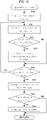
- Fig. 4 is a flow chart showing an operation of the CPU 103.
- the CPU 103 on receiving edit instructions of widgets through the user I/F 102, causes an edit screen shown in Fig. 3 to open (S11).
- the CPU 103 places a main widget (S12) at first.
- the main widget is a widget that integrates a plurality of below-mentioned sub-widgets into one.
- the alert indicator 85, the ON/OFF button 86, the slider 87, the knob 88 and the meter 89 are each correspond to a main widget.
- the user can, as indicated on the right side in the edit screen in the diagram, place main widgets that are going to be used by drugging and dropping a plurality of main widgets.
- the CPU 103 determines whether or not the user has selected a main widget (S13). If the user does not select a main widget (S13, No), the CPU 103 repeats the determination of S13. If the user selects a main widget (S13, Yes), the CPU 103, as shown in Fig. 5 , causes a balloon for sub-widgets to be displayed (S14), and then causes the sub-widgets to be displayed in the balloon (S15). For example, in Fig. 5 , since the user has selected the alert indicator 85, the CPU 103 causes a balloon image 850 corresponding to the alert indicator 85 to be displayed. Then, the CPU 103 causes a plurality of sub-widgets to be displayed inside the balloon image 850.
- the CPU 103 causes four sub-widgets consisting of a sub-indicator 851, a sub-indicator 852, a sub-indicator 853 and a sub-indicator 854 to be displayed.
- the number of sub-widgets displayed in the balloon image 850 can also be specified by the user, and so can deletion or addition thereof be made.
- Each sub-widget is associated with a predetermined device or a predetermined function.
- the sub-indicator 851 is associated with the amplifier 15
- the sub-indicator 852 is associated with the audio mixer 13
- the sub-indicator 853 is associated with the speaker 16
- the sub-indicator 854 is associated with the audio I/O unit 14.
- a sub-widget can even be associated with, instead of an entire device, one constituent of the device (for example, a heat sink for one channel of the amplifier, or the like).
- each sub-widget can be associated with a predetermined function (for example, a level controller) installed on each device.
- the laptop PC 11 may detect devices inside the system by performing a network search or the like and then automatically associate each sub-widget with each device; otherwise, the user may manually associate any sub-widget with any device or any function.
- the laptop PC 11 may, for example, obtain information on a device name (for example, computer name, MAC address, IP address, or the like) and then associate a sub-widget with the device name.
- Fig. 6 is a flow chart showing an editing operation of a sub-widget
- Fig. 7 is a diagram showing an example of an edit screen.
- the CPU 103 determines whether or not the user has selected a sub-widget (S21). If the user does not select a sub-widget, the CPU 103 repeats the determination of S13 (S21, No). If the user has selected each sub-widget and has given edit instructions (S21, Yes), the CPU 103 causes the sub-widget edit screen as shown in Fig. 7 to be displayed, and receives each editing operation (S22).
- the user can edit device name (Model), Device Identifier, function name (Parameter), channel number (Channel), condition and so forth.
- the device name is automatically inputted by contacting the target device and so on; otherwise, the user can edit freely.
- the device identifier although an IP address is displayed in the example of Fig. 7 , a MAC address or specific identification information such as serial number or the like may be used, instead.
- a function name becomes capable of being edited when a sub-widget is associated with a predetermined function in a predetermined device.
- "Output Level" is displayed as the function name.
- the channel number corresponds to a channel number for the parameter that is associated with the sub-widget. In this example, channel 1 is set. Therefore, the sub-indicator 852 becomes a widget to indicate a state (alert) of the level controller of the output channel 1 of the audio mixer 13.
- the condition (threshold value) indicated in the bottom line means a condition that is set for the sub-widget.
- each predetermined condition is set.
- the sub-indicator 851 is associated with the heat sink for the channel 1 of the amplifier 15. Since the sub-indicator 851 is an alert indicator, for the sub-indicator 851 an alert condition is set.
- a condition of +5dB is set as a level of the output channel 1. Thus, when the level of the output channel 1 of the audio mixer 13 becomes greater than or equal to +5dB, the condition for the sub-indicator 852 is met.
- the CPU 103 performs an alert notification by causing a corresponding widget (indicator) to be turned on or blinked. Otherwise, the CPU 103 may perform an alert notification by causing an indication color of the indicator to change.
- the indication color becomes yellow in a case where the level becomes greater than or equal to +3dB, and red in a case where the level becomes greater than or equal to +5dB.
- Fig. 8 is a flow chart showing an operation of the CPU 103 in a case of setting a relationship between conditions set for the sub-widgets and a condition set for the main widget.
- Fig. 9 is a diagram showing an example of a relationship setting screen.
- the CPU 103 determines whether or not the user has selected a relationship setting button 859 (S31). If the user does not select the relationship setting button 859, the CPU 103 repeats the determination of S31 (S31, No). If the user selects the relationship setting button 859 (S31, Yes), the CPU 103 causes a screen for setting a relationship between conditions set for the sub-widgets and a condition set for the main widget as shown in Fig. 9 to be displayed (S32).
- the user selects, as the relationship between conditions set for the sub-widgets and a condition set for the main widget, a logical expression of the conditions set for a plurality of sub-widgets, for example.
- a logical expression of the conditions set for a plurality of sub-widgets for example.
- the user selects one from among "AND”, “OR”, “XOR” and "XNOR”.
- the CPU 103 decides, as the relationship, that the condition for the main widget is met when all the conditions for the sub-widgets are met.
- the alert condition for the alert indicator 85 as the main widget is met when all the alert conditions for the sub-indicator 851, the sub-indicator 852, the sub-indicator 853 and the sub-indicator 854 are met.
- the CPU 103 decides, as the relationship, that the condition for the main widget is met when a condition for any one corresponding sub-widget is met.
- the CPU 103 decides, as the relationship, that the condition for the main widget is met when states of all the sub-widgets match. That is, the alert condition for the alert indicator 85 as the main widget is met when all the alert conditions for the sub-indicator 851, the sub-indicator 852, the sub-indicator 853 and the sub-indicator 854 are met, or when all the alert conditions for the sub-indicator 851, the sub-indicator 852, the sub-indicator 853 and the sub-indicator 854 are not met.
- the CPU 103 decides, as the relationship, that the condition for the main widget is met when states of the sub-widgets are different from each other. That is, the CPU 103 decides that the condition for the main widget is met when at least any one of the alert conditions for the sub-indicator 851, the sub-indicator 852, the sub-indicator 853 and the sub-indicator 854 are not met while the alert condition(s) for the other sub-indicator(s) are met, or when at least any one of the alert conditions for the sub-indicator 851, the sub-indicator 852, the sub-indicator 853 and the sub-indicator 854 are met while the alert condition(s) for the other sub-indicator (s) are not met.
- the user may also set a relationship such that the condition for the main widget is met when the number of the sub-widgets the conditions for which are met reaches a predetermined number (3, for example). Further, it is also possible to set multi-step relationships with the indication color of the main widget being changed multi-stepwise. On decision that a first-step condition for the main widget is met when the conditions for two sub-widgets are met, the indication color of the main widget (alert indicator 85) is changed to yellow. On decision that a second-step condition for the main widget is met when the conditions for all the sub-widgets are met, the indication color of the main widget (alert indicator 85) is changed to red.
- the user can cause an alert notification when a specific condition for a specific device or a specific function is met.
- setting of greater than or equal to 0dB is also acceptable, so that it is possible to cause the level of the output signal to be greater than that of the input signal.
- the greater-than-or-equal-to-zero dB setting for a fader of a certain portion on the sound system influence slightly; however, if many greater-than-or-equal-to-zero dB settings are made for a plurality of portions, there is a possibility that the signal level increases substantially.
- the user sets the condition for each sub-widget such that each fader value is greater than or equal to 0dB, and sets "AND" as the relationship. This makes it possible to perform an alert notification on decision that the condition for the main widget is met when the fader values for a plurality of faders become greater than or equal to 0dB simultaneously.
- Fig. 10 is a flow chart showing an operation of the PC in an operating mode.
- Fig. 11A, Fig. 11B and Fig. 11C are diagrams showing an example of the display screen in the operating mode.
- the operating mode may be carried out in the laptop PC 11, in this embodiment, it is assumed that the operation shown in Fig. 10 is carried out in the tablet PC 12 that has increased portability.
- the tablet PC 12 has a configuration same or similar to that of the laptop PC 11 shown in Fig. 2 .
- the CPU 103 obtains information on each device or each function thereof that is connected through the network (S41).
- a parameter value level, temperature, power consumption, load impedance or the like
- a parameter value for a function as a management target is transmitted from each device.
- the CPU 103 comparing an obtained present value for each device or each function with a condition (threshold value) set for each sub-widget to check if or not a condition for each sub-widget is met (S42).
- the CPU 103 on determining that a condition for a sub-widget is met (S42, Yes), causes the state of the relevant sub-widget to change (S43).
- the CPU 103 on determining that a condition for a sub-widget is not met (S42, No), omits the processing of S43.
- Fig. 11A since the main widgets are displayed but no sub-widget is displayed on the management screen, it is not possible to be visually recognized that there is a change in state of any sub-widget until the condition for a main widget is met.
- the CPU 103 determines whether or not a condition for a main widget is met (S44).
- the CPU 103 determines that the condition for the main widget is met when one or more conditions for the sub-widgets meet the above-mentioned relationship (logical expression).
- the CPU 103 causes the indication of the main widget to change (S45). For example, as shown in Fig. 11B , the CPU 103 causes the alert indicator 85 to be turned on.
- the CPU 103 on determining that the condition for the main widget is not met (S44, No), repeats form the processing of S41.
- the CPU 103 After completing the processing of S45, the CPU 103 further determines whether or not the selection of a main widget has been made (S46). When a main widget is selected (S46, Yes), the CPU 103 causes sub-widgets corresponding to the selected main widget to be displayed (S47). The CPU 103, on determining that a main widget is not selected (S46, No), omits the processing of S47.
- the CPU causes the sub-indicator 851, the sub-indicator 852, the sub-indicator 853 and the sub-indicator 854 to be displayed.
- a device name is displayed for each sub-widget.
- names for these function and channel are also displayed.
- both the alert indicator 85 and the sub-indicator 852 are in turn-on states.
- Fig. 11D in a case where the level controller of the input channel 1 is assigned to the sub-indicator 851, where the level controller of the output channel 1 is assigned to the sub-indicator 852, and where a gain of a compressor of the input channel 1 is assigned to the sub-indicator 853, and when "AND" is set as the relationship with the main widget, the alert indicator 85 remains turned-off even when the level of the output channel 1 of the audio mixer 13 exceeds a predetermined threshold value.
- the sound system according to the embodiment of the present invention makes it possible to manage a plurality of any devices or any functions integrally through the main widget even when the number of the devices increases.
- a procedure that each device performs an operation of comparing a present value with a condition (threshold value) for a sub-widget and that if the condition is met (if the threshold value is exceeded by the present value) information to the effect that the condition is met is transmitted from the device to the tablet PC 12 may be acceptable.
- such a procedure that the tablet PC 12 compares a present value obtained from a certain device with the condition whereas from another device if the condition for the sub-widget is met (if the threshold value is exceeded by the present value) information to the effect that the condition is met is transmitted to the tablet PC 12 may be acceptable.
- the ON/OFF button 86, the slider 87, the knob 88 and the meter 89 meet the conditions for the main widgets when values for the respective sub-widgets meet predetermined conditions.
- the display of the ON/OFF button 86 can be changed to "ON" state when the devices (or the functions) associated with all the sub-widgets are turned on.
- the value (fader value) of the slider 87 indicates - ⁇ dB when fader values associated with all the sub-widgets (a plurality of faders) are not greater than a predetermined threshold value (for example, 0dB), and that the value of the slider 87 indicates 0dB when the fader values associated with all the sub-widgets exceeds a predetermined threshold value (for example, 0dB).
- a predetermined threshold value for example, 0dB
- a predetermined threshold value for example, 0dB
- the user can deem that settings that exceed 0dB are made at the same time at a plurality of portions when the value of the slider 87 of the main widget changes to 0dB.
- the value of the knob 88 indicates a minimum value when gains associated with all the sub-widgets (a plurality of knobs) are not greater than threshold values, and that the value of the knob 88 indicates a maximum value when the values of the knobs associated with all the sub-widgets exceed the threshold values.
Landscapes
- Engineering & Computer Science (AREA)
- Theoretical Computer Science (AREA)
- General Engineering & Computer Science (AREA)
- Physics & Mathematics (AREA)
- General Physics & Mathematics (AREA)
- Human Computer Interaction (AREA)
- Acoustics & Sound (AREA)
- Signal Processing (AREA)
- Quality & Reliability (AREA)
- User Interface Of Digital Computer (AREA)
- Circuit For Audible Band Transducer (AREA)
Abstract
Description
- The present invention, in some embodiments thereof, relates to an information display apparatus, an information display method and a program that display information.
- An application program described in
Non Patent Literature 1 has a function to perform a remote control and remote monitoring of a plurality of amplifiers. The application program accepts, for example, a setting of a threshold value for a temperature of a heat sink. With the application program, a warning is emitted when the temperature of the heat sink exceeds the threshold value. - [Non Patent Literature 1] Network Amp Manager, [online], [Searched on Sept. 30, 2016], Internet <URL:http//www.yamahaproaudio.com/japan/ja/products/perip herals/applications/networkampmanager/features.jsp>
- However, the application program described in
Non Patent Literature 1 is the one that performs individual management of a plurality of devices, and thus has been unable to perform management of as far as the entire system. As the number of devices within a system increases, the number of objects to manage increases; then, it becomes difficult to perform management of the entire system. - On that account, the present invention, in some embodiments thereof, is directed to providing an information display apparatus, an information display method and a program that are capable of performing management of an entire system.
- An information display apparatus includes a display portion and a control portion. The display portion displays widgets that include a main widget and a plurality of sub-widgets that indicate a state of a device or a state of a function installed on the device. The control portion executes: a process of placing a plurality of sub-widgets against the main widget; a process of setting the device or the function that is associated with each of the plurality of sub-widgets; a process of setting a condition for the device or a condition for the function that is associated with each of the plurality of sub-widgets; and a process of setting a relationship between conditions set for the plurality of sub-widgets and a condition set for the main widget.
- The information display apparatus is capable of performing management of an entire system.
-
-
Fig. 1 is a block diagram showing a configuration of a sound system. -
Fig. 2 is a block diagram showing a configuration of a PC. -
Fig. 3 is a diagram showing an example of a GUI. -
Fig. 4 is a flow chart showing an operation of the PC. -
Fig. 5 is a diagram showing an example of the GUI. -
Fig. 6 is a flow chart showing an editing operation of a sub-widget. -
Fig. 7 is a diagram showing an example of an edit screen. -
Fig. 8 is a flow chart showing an operation of the PC. -
Fig. 9 is a diagram showing an example of a relationship setting screen. -
Fig. 10 is a flow chart showing an operation of the PC in an operating mode. -
Fig. 11A -Fig. 11D are diagrams showing examples of the GUI in the operating mode. - An information display apparatus according to an embodiment of the present invention sets a main widget that integrates a plurality of sub-widgets. Also, the information display apparatus sets a condition for each sub-widget, and sets a relationship between conditions for the sub-widget and the main widget. Thus, by performing management of the main widget, the user can perform management of states of a plurality of devices or functions that are allocated to a plurality of sub-widgets.
-
Fig. 1 is a block diagram showing a configuration of a sound system. The sound system includes a laptop PC 11, atablet PC 12, anaudio mixer 13, an audio I/O unit 14, anamplifier 15, aspeaker 16 and a LAN (Local Area Network) 20. The laptop PC 11, the tablet PC 12, theaudio mixer 13, the audio I/O unit 14, theamplifier 15 and thespeaker 16 are connected to each other through theLAN 20. However, in the present invention, connection mode for each device is not limited to a network connection through a LAN. For example, each device may be connected through a MIDI (Musical Instrument Digital Interface). - The laptop PC 11 and the tablet PC 12 are respectively examples of the information display apparatus of the present invention, and are general purpose computers (information processing devices).
Fig. 2 is a block diagram showing a configuration of thePC 11. The laptop PC 11 includes adisplay 101, a user interface (I/F) 102, aCPU 103, aflash ROM 104, aRAM 105 and a network interface (I/F) 106. These components are connected to abus 151. The tablet PC 12 also has a configuration similar to that of the laptop PC 11. - The
display 101 consists of, for example, a LCD (Liquid Crystal Display), and displays various information. The user I/F 102 consists of, for example, a mouse, a keyboard, a touch panel and/or the like, and receives user's operation. The user I/F 102, together with thedisplay 101, constitutes a GUI (Graphical User Interface). - The
CPU 103 corresponds to a control portion, an information obtaining portion and so forth of the present invention. TheCPU 103 reads out a program that is stored in theflash ROM 104, which is a storage medium, into theRAM 105 and realizes a predetermined function. For example, theCPU 103 realizes a GUI by causing thedisplay 101 to display an image of an operation portion (receiving portion) for receiving a user's operation and then by receiving, through the user I/F 102, a selection operation or the like to an image of the operation portion. Here, the program is not necessarily stored in theflash ROM 104 in the own apparatus, but may be stored in a storage medium in an external device such as a server or the like, as is well-known. In such a case, theCPU 103 may each time read out the program from the server into theRAM 105 to execute. -
Fig. 3 is an example of a GUI displayed on thedisplay 101. With the GUI shown in this example, the user performs operations such as placement of widgets, setting of devices or functions that are to be associated with the widgets, and so forth. A widget is an element to constitute a GUI. In the example ofFig. 3 , as widgets, analert indicator 85, an ON/OFF button 86, aslider 87, aknob 88 and ameter 89 are displayed. -
Fig. 4 is a flow chart showing an operation of theCPU 103. TheCPU 103, on receiving edit instructions of widgets through the user I/F 102, causes an edit screen shown inFig. 3 to open (S11). - In the edit screen, the
CPU 103 places a main widget (S12) at first. The main widget is a widget that integrates a plurality of below-mentioned sub-widgets into one. In the example ofFig. 3 , thealert indicator 85, the ON/OFF button 86, theslider 87, theknob 88 and themeter 89 are each correspond to a main widget. The user can, as indicated on the right side in the edit screen in the diagram, place main widgets that are going to be used by drugging and dropping a plurality of main widgets. - Then, the
CPU 103 determines whether or not the user has selected a main widget (S13). If the user does not select a main widget (S13, No), theCPU 103 repeats the determination of S13. If the user selects a main widget (S13, Yes), theCPU 103, as shown inFig. 5 , causes a balloon for sub-widgets to be displayed (S14), and then causes the sub-widgets to be displayed in the balloon (S15). For example, inFig. 5 , since the user has selected thealert indicator 85, theCPU 103 causes aballoon image 850 corresponding to thealert indicator 85 to be displayed. Then, theCPU 103 causes a plurality of sub-widgets to be displayed inside theballoon image 850. In this example, theCPU 103 causes four sub-widgets consisting of a sub-indicator 851, a sub-indicator 852, a sub-indicator 853 and a sub-indicator 854 to be displayed. The number of sub-widgets displayed in theballoon image 850 can also be specified by the user, and so can deletion or addition thereof be made. - Each sub-widget is associated with a predetermined device or a predetermined function. For example, the sub-indicator 851 is associated with the
amplifier 15, the sub-indicator 852 is associated with theaudio mixer 13, the sub-indicator 853 is associated with thespeaker 16, and the sub-indicator 854 is associated with the audio I/O unit 14. Further, a sub-widget can even be associated with, instead of an entire device, one constituent of the device (for example, a heat sink for one channel of the amplifier, or the like). Also, each sub-widget can be associated with a predetermined function (for example, a level controller) installed on each device. - Moreover, the
laptop PC 11 may detect devices inside the system by performing a network search or the like and then automatically associate each sub-widget with each device; otherwise, the user may manually associate any sub-widget with any device or any function. In the case where each sub-widget is automatically associated with each device, thelaptop PC 11 may, for example, obtain information on a device name (for example, computer name, MAC address, IP address, or the like) and then associate a sub-widget with the device name. - Subsequently,
Fig. 6 is a flow chart showing an editing operation of a sub-widget, andFig. 7 is a diagram showing an example of an edit screen. - The
CPU 103 determines whether or not the user has selected a sub-widget (S21). If the user does not select a sub-widget, theCPU 103 repeats the determination of S13 (S21, No). If the user has selected each sub-widget and has given edit instructions (S21, Yes), theCPU 103 causes the sub-widget edit screen as shown inFig. 7 to be displayed, and receives each editing operation (S22). - The user can edit device name (Model), Device Identifier, function name (Parameter), channel number (Channel), condition and so forth.
- The device name is automatically inputted by contacting the target device and so on; otherwise, the user can edit freely. As to the device identifier, although an IP address is displayed in the example of
Fig. 7 , a MAC address or specific identification information such as serial number or the like may be used, instead. A function name becomes capable of being edited when a sub-widget is associated with a predetermined function in a predetermined device. In this example, in order to perform management of a level controller (fader) of anoutput channel 1 with the sub-indicator 852 being associated with theaudio mixer 13, "Output Level" is displayed as the function name. The channel number corresponds to a channel number for the parameter that is associated with the sub-widget. In this example,channel 1 is set. Therefore, the sub-indicator 852 becomes a widget to indicate a state (alert) of the level controller of theoutput channel 1 of theaudio mixer 13. - The condition (threshold value) indicated in the bottom line means a condition that is set for the sub-widget. For a device or a function that is associated with each sub-widget, each predetermined condition is set. For example, the sub-indicator 851 is associated with the heat sink for the
channel 1 of theamplifier 15. Since the sub-indicator 851 is an alert indicator, for the sub-indicator 851 an alert condition is set. Also, in the example shown inFig. 7 , for the sub-indicator 852 a condition of +5dB is set as a level of theoutput channel 1. Thus, when the level of theoutput channel 1 of theaudio mixer 13 becomes greater than or equal to +5dB, the condition for the sub-indicator 852 is met. If the condition is met, theCPU 103 performs an alert notification by causing a corresponding widget (indicator) to be turned on or blinked. Otherwise, theCPU 103 may perform an alert notification by causing an indication color of the indicator to change. Moreover, it is also possible to set multi-step conditions with the indication color being changed multi-stepwise. For example, the indication color becomes yellow in a case where the level becomes greater than or equal to +3dB, and red in a case where the level becomes greater than or equal to +5dB. - In the above-mentioned manner, the user can edit each sub-widget. Next,
Fig. 8 is a flow chart showing an operation of theCPU 103 in a case of setting a relationship between conditions set for the sub-widgets and a condition set for the main widget.Fig. 9 is a diagram showing an example of a relationship setting screen. - The
CPU 103 determines whether or not the user has selected a relationship setting button 859 (S31). If the user does not select therelationship setting button 859, theCPU 103 repeats the determination of S31 (S31, No). If the user selects the relationship setting button 859 (S31, Yes), theCPU 103 causes a screen for setting a relationship between conditions set for the sub-widgets and a condition set for the main widget as shown inFig. 9 to be displayed (S32). - The user selects, as the relationship between conditions set for the sub-widgets and a condition set for the main widget, a logical expression of the conditions set for a plurality of sub-widgets, for example. In the example of
Fig. 9 , the user selects one from among "AND", "OR", "XOR" and "XNOR". When "AND" is selected, theCPU 103 decides, as the relationship, that the condition for the main widget is met when all the conditions for the sub-widgets are met. As a result, the alert condition for thealert indicator 85 as the main widget is met when all the alert conditions for the sub-indicator 851, the sub-indicator 852, the sub-indicator 853 and the sub-indicator 854 are met. - When "OR" is selected, the
CPU 103 decides, as the relationship, that the condition for the main widget is met when a condition for any one corresponding sub-widget is met. When "XOR" is selected, theCPU 103 decides, as the relationship, that the condition for the main widget is met when states of all the sub-widgets match. That is, the alert condition for thealert indicator 85 as the main widget is met when all the alert conditions for the sub-indicator 851, the sub-indicator 852, the sub-indicator 853 and the sub-indicator 854 are met, or when all the alert conditions for the sub-indicator 851, the sub-indicator 852, the sub-indicator 853 and the sub-indicator 854 are not met. - When "XNOR" is selected, the
CPU 103 decides, as the relationship, that the condition for the main widget is met when states of the sub-widgets are different from each other. That is, theCPU 103 decides that the condition for the main widget is met when at least any one of the alert conditions for the sub-indicator 851, the sub-indicator 852, the sub-indicator 853 and the sub-indicator 854 are not met while the alert condition(s) for the other sub-indicator(s) are met, or when at least any one of the alert conditions for the sub-indicator 851, the sub-indicator 852, the sub-indicator 853 and the sub-indicator 854 are met while the alert condition(s) for the other sub-indicator (s) are not met. - Additionally, the user may also set a relationship such that the condition for the main widget is met when the number of the sub-widgets the conditions for which are met reaches a predetermined number (3, for example). Further, it is also possible to set multi-step relationships with the indication color of the main widget being changed multi-stepwise. On decision that a first-step condition for the main widget is met when the conditions for two sub-widgets are met, the indication color of the main widget (alert indicator 85) is changed to yellow. On decision that a second-step condition for the main widget is met when the conditions for all the sub-widgets are met, the indication color of the main widget (alert indicator 85) is changed to red.
- This enables the user to manage a plurality of devices or a plurality of functions integrally through one main widget, and thus to manage an entire sound system. For example, in a case where the user sets device temperatures as the conditions for a plurality of sub-widgets and sets "OR" as the relationship, it is possible to perform an alert notification on decision that the condition for the main widget is met when a temperature of any one of the devices in the sound system exceeds a threshold value.
- Also, it is possible for the user to cause an alert notification when a specific condition for a specific device or a specific function is met. For example, in the fader of the mixer, setting of greater than or equal to 0dB is also acceptable, so that it is possible to cause the level of the output signal to be greater than that of the input signal. The greater-than-or-equal-to-zero dB setting for a fader of a certain portion on the sound system influence slightly; however, if many greater-than-or-equal-to-zero dB settings are made for a plurality of portions, there is a possibility that the signal level increases substantially. On that account, the user sets the condition for each sub-widget such that each fader value is greater than or equal to 0dB, and sets "AND" as the relationship. This makes it possible to perform an alert notification on decision that the condition for the main widget is met when the fader values for a plurality of faders become greater than or equal to 0dB simultaneously.
- Subsequently,
Fig. 10 is a flow chart showing an operation of the PC in an operating mode.Fig. 11A, Fig. 11B and Fig. 11C are diagrams showing an example of the display screen in the operating mode. Although the operating mode may be carried out in thelaptop PC 11, in this embodiment, it is assumed that the operation shown inFig. 10 is carried out in thetablet PC 12 that has increased portability. Thetablet PC 12 has a configuration same or similar to that of thelaptop PC 11 shown inFig. 2 . - The
CPU 103 of thetablet PC 12, in the operating mode, first causes a management screen as shown inFig. 11A to be displayed (S40). On the management screen, as shown inFig. 11A , only the main widgets are displayed, and no sub-widget is displayed. Therefore, the management screen occupies just a small area on the display; and this is preferable for mobile information processing devices such as tablet PC 12 (or smart phone) or the like with a small display area. - The
CPU 103 obtains information on each device or each function thereof that is connected through the network (S41). A parameter value (level, temperature, power consumption, load impedance or the like) for a function as a management target is transmitted from each device. - The
CPU 103, comparing an obtained present value for each device or each function with a condition (threshold value) set for each sub-widget to check if or not a condition for each sub-widget is met (S42). TheCPU 103, on determining that a condition for a sub-widget is met (S42, Yes), causes the state of the relevant sub-widget to change (S43). TheCPU 103, on determining that a condition for a sub-widget is not met (S42, No), omits the processing of S43. However, in the example ofFig. 11A , since the main widgets are displayed but no sub-widget is displayed on the management screen, it is not possible to be visually recognized that there is a change in state of any sub-widget until the condition for a main widget is met. - Then, the
CPU 103 determines whether or not a condition for a main widget is met (S44). TheCPU 103 determines that the condition for the main widget is met when one or more conditions for the sub-widgets meet the above-mentioned relationship (logical expression). When the condition for the main widget is met (S44, Yes), theCPU 103 causes the indication of the main widget to change (S45). For example, as shown inFig. 11B , theCPU 103 causes thealert indicator 85 to be turned on. TheCPU 103, on determining that the condition for the main widget is not met (S44, No), repeats form the processing of S41. - After completing the processing of S45, the
CPU 103 further determines whether or not the selection of a main widget has been made (S46). When a main widget is selected (S46, Yes), theCPU 103 causes sub-widgets corresponding to the selected main widget to be displayed (S47). TheCPU 103, on determining that a main widget is not selected (S46, No), omits the processing of S47. - For example, as shown in
Fig. 11C , when thealert indicator 85 is selected, the CPU causes the sub-indicator 851, the sub-indicator 852, the sub-indicator 853 and the sub-indicator 854 to be displayed. In this example, for each sub-widget a device name is displayed. In a case of performing management of a specific function and a specific channel, names for these function and channel are also displayed. - In the example of
Fig. 11C , because the level of theoutput channel 1 of theaudio mixer 13 exceeds a predetermined threshold value and "OR" is set as the relationship with the main widget, both thealert indicator 85 and the sub-indicator 852 are in turn-on states. As shown inFig. 11D , in a case where the level controller of theinput channel 1 is assigned to the sub-indicator 851, where the level controller of theoutput channel 1 is assigned to the sub-indicator 852, and where a gain of a compressor of theinput channel 1 is assigned to the sub-indicator 853, and when "AND" is set as the relationship with the main widget, thealert indicator 85 remains turned-off even when the level of theoutput channel 1 of theaudio mixer 13 exceeds a predetermined threshold value. - As stated above, the sound system according to the embodiment of the present invention makes it possible to manage a plurality of any devices or any functions integrally through the main widget even when the number of the devices increases.
- Further, although, in the operation example of
Fig. 10 , an example in which thetablet PC 12 obtains a present value of each function from each device is shown, instead, for example, such a procedure that each device performs an operation of comparing a present value with a condition (threshold value) for a sub-widget and that if the condition is met (if the threshold value is exceeded by the present value) information to the effect that the condition is met is transmitted from the device to thetablet PC 12 may be acceptable. - Also, such a procedure that the
tablet PC 12 compares a present value obtained from a certain device with the condition whereas from another device if the condition for the sub-widget is met (if the threshold value is exceeded by the present value) information to the effect that the condition is met is transmitted to thetablet PC 12 may be acceptable. - The above explanations of the embodiments are nothing more than illustrative in any respect, and are not restrictive. Scope of the present invention is indicated by claims rather than the above embodiments. Further, it is intended that all changes that are equivalent to a claim in the sense and realm of the doctrine of equivalence be included within the scope of the present invention. For example, as stated above, since each device may be connected through the MIDI, naturally, electronic instruments are also among examples of the devices capable of being associated with the sub-widgets. Of course, the equipment capable of being associated with a sub-widget is not limited to audio equipment. For example, communication equipment such as rooter, hub, switch or the like may also be associated with a sub-widget. Also, for example, it is possible to define that the ON/
OFF button 86, theslider 87, theknob 88 and themeter 89 meet the conditions for the main widgets when values for the respective sub-widgets meet predetermined conditions. For example, in the case of the ON/OFF button 86, the display of the ON/OFF button 86 can be changed to "ON" state when the devices (or the functions) associated with all the sub-widgets are turned on. Moreover, for example, in the case of theslider 87, it is also possible to define that the value (fader value) of theslider 87 indicates - ∞ dB when fader values associated with all the sub-widgets (a plurality of faders) are not greater than a predetermined threshold value (for example, 0dB), and that the value of theslider 87 indicates 0dB when the fader values associated with all the sub-widgets exceeds a predetermined threshold value (for example, 0dB). As above-mentioned, in the case of the mixer, if settings that exceed 0dB are made at the same time at a plurality of portions, there is a possibility that the signal level increases significantly. In the case of this example, the user can deem that settings that exceed 0dB are made at the same time at a plurality of portions when the value of theslider 87 of the main widget changes to 0dB. In the same manner, in the case of theknob 88 as well, it is also possible to define that the value of theknob 88 indicates a minimum value when gains associated with all the sub-widgets (a plurality of knobs) are not greater than threshold values, and that the value of theknob 88 indicates a maximum value when the values of the knobs associated with all the sub-widgets exceed the threshold values. -
- 11 ---
- laptop PC
- 12 ---
- tablet PC
- 13 ---
- audio mixer
- 14 ---
- audio I/O unit
- 15 ---
- amplifier
- 16 ---
- speaker
- 20 ---
- LAN
- 85 ---
- alert indicator
- 86 ---
- OFF button
- 87 ---
- slider
- 88 ---
- knob
- 89 ---
- meter
- 101 ---
- display
- 102 ---
- user I/F
- 103 ---
- CPU
- 104 ---
- flash ROM
- 105 ---
- RAM
- 101 ---
- network I/F
- 151 ---
- bus
- 850 ---
- image
- 851, 852, 853, 854 ---
- sub-indicator
Claims (12)
- An information display apparatus comprising:a display portion that displays widgets including a main widget and a plurality of sub-widgets that indicate states of devices or states of functions installed on the devices; anda control portion that executes:a process of placing the plurality of sub-widgets against the main widget;a process of setting the device or the function that is associated with each of the plurality of sub-widgets;a process of setting a condition for the device or a condition for the function that is associated with each of the plurality of sub-widgets; anda process of setting a relationship between conditions set for the plurality of sub-widgets and a condition set for the main widget.
- The information display apparatus according to Claim 1 comprising a receiving portion that receives user's operation, wherein
the control portion obtains, through the receiving portion, setting of a threshold value as the setting of the condition; and
the main widget and the sub-widget are indicators that are turned on when a present value of the device or the function exceeds the threshold value. - The information display apparatus according to Claim 1 or Claim 2, wherein
the relationship between the sub-widget and the main widget is such that the condition for the main widget is defined by a logical expression of the conditions set for the plurality of sub-widgets. - The information display apparatus according to any of Claim 1 to Claim 3 further comprising an information obtaining portion that obtains information from the device, wherein
the control portion causes display of the main widget to change on deciding that the condition for the main widget is met when the information from the device that is obtained by the information obtaining section meets the condition with respect to at least one sub-widget among the plurality of sub-widgets. - The information display apparatus according to any of Claim 1 to Claim 3 further comprising an information obtaining portion that obtains information from the device, wherein
the control portion causes display of the main widget to change on deciding that the condition for the main widget is met when the information from the device that is obtained by the information obtaining section meets the condition with respect to all the sub-widgets among the plurality of sub-widgets. - The information display apparatus according to any of Claim 1 to Claim 3 further comprising an information obtaining portion that obtains information from the device, wherein
the control portion causes display of the main widget to change on deciding that the condition for the main widget is met when the information from the device that is obtained by the information obtaining section meets the condition with respect to all the sub-widgets among the plurality of sub-widgets, or when the information from the device that is obtained by the information obtaining section does not meet the condition with respect to all the sub-widgets among the plurality of sub-widgets. - The information display apparatus according to any of Claim 1 to Claim 3 further comprising an information obtaining portion that obtains information from the device, wherein
the control portion causes an indication of the main widget to change on deciding that the condition for the main widget is met when the information from the device that is obtained by the information obtainer does not meet the condition with respect to at least any one sub-widget among the plurality of sub-widgets and meets the condition with respect to at least any one sub-widget among other sub-widgets, or when the information from the device that is obtained by the information obtainer meets the condition with respect to at least any one sub-widget among the plurality of sub-widgets and does not meet the condition with respect to at least any one sub-widget among other sub-widgets. - The information display apparatus according to any of Claim 4 to Claim 7, wherein
the information from the device is obtained, when a predetermined operation is performed at the device, as information showing details of the predetermined operation. - The information display apparatus according to any of Claim 1 to Claim 8, wherein
the device includes audio equipment; and
the main widget or at least one sub-widget indicate a state of the audio equipment or the function installed on the audio equipment. - The information display apparatus according to any of Claim 1 to Claim 9, wherein
the main widget is the alert indicator. - An information display method performing:a process of displaying widgets that include a main widget and a plurality of sub-widgets that indicate states of devices or states of functions installed on the devices;a process of placing a plurality of sub-widgets against the main widget;a process of setting the device or the function that is associated with each of the plurality of sub-widgets;a process of setting a condition for the device or a condition for the function that is associated with each of the plurality of sub-widgets; anda process of setting a relationship between conditions set for the plurality of sub-widgets and a condition set for the main widget.
- A program executed in an information display apparatus, the information display apparatus comprising:a display portion that displays a widget for indicating a state of a device or a state of a function installed on the device; anda control portion,the widget including a main widget and a sub-widget,
the program causing the control portion to execute:a process of placing a plurality of sub-widgets against the main widget;a process of setting the device or the function that is associated with each of the plurality of sub-widgets;a process of setting a condition for the device or a condition for the function that is associated with each of the plurality of sub-widgets; anda process of setting a relationship between conditions set for the plurality of sub-widgets and a condition set for the main widget.
Applications Claiming Priority (2)
| Application Number | Priority Date | Filing Date | Title |
|---|---|---|---|
| JP2016213966A JP6926443B2 (en) | 2016-11-01 | 2016-11-01 | Information display device, information display method and program |
| PCT/JP2017/037798 WO2018083991A1 (en) | 2016-11-01 | 2017-10-19 | Information display device, information display method, and program |
Publications (3)
| Publication Number | Publication Date |
|---|---|
| EP3537275A1 true EP3537275A1 (en) | 2019-09-11 |
| EP3537275A4 EP3537275A4 (en) | 2020-06-24 |
| EP3537275B1 EP3537275B1 (en) | 2025-08-20 |
Family
ID=62076708
Family Applications (1)
| Application Number | Title | Priority Date | Filing Date |
|---|---|---|---|
| EP17867810.8A Active EP3537275B1 (en) | 2016-11-01 | 2017-10-19 | Information display device, information display method, and program |
Country Status (5)
| Country | Link |
|---|---|
| US (1) | US11048398B2 (en) |
| EP (1) | EP3537275B1 (en) |
| JP (1) | JP6926443B2 (en) |
| CN (1) | CN109891376B (en) |
| WO (1) | WO2018083991A1 (en) |
Families Citing this family (5)
| Publication number | Priority date | Publication date | Assignee | Title |
|---|---|---|---|---|
| US9361011B1 (en) | 2015-06-14 | 2016-06-07 | Google Inc. | Methods and systems for presenting multiple live video feeds in a user interface |
| JP7452280B2 (en) | 2020-06-19 | 2024-03-19 | ヤマハ株式会社 | Information processing terminals, audio systems, information processing methods and programs |
| CN111857929B (en) * | 2020-07-23 | 2023-05-30 | 杭州海康威视数字技术股份有限公司 | Application program interface display method, device and computer equipment |
| JP7505377B2 (en) * | 2020-11-11 | 2024-06-25 | 新東工業株式会社 | Information processing method, information processing system, and program |
| CN116679861A (en) * | 2022-11-30 | 2023-09-01 | 荣耀终端有限公司 | A content display method and electronic device thereof |
Family Cites Families (11)
| Publication number | Priority date | Publication date | Assignee | Title |
|---|---|---|---|---|
| US4862159A (en) * | 1988-04-18 | 1989-08-29 | Audio Technology, Inc. | Centralized system for selecting and reproducing perceptible programs |
| JPH08335111A (en) * | 1995-06-07 | 1996-12-17 | Mitsubishi Electric Corp | Man-machine equipment for plant monitoring |
| JP4808030B2 (en) * | 2006-01-12 | 2011-11-02 | ヤフー株式会社 | E-mail warning device, mail server, and e-mail warning method |
| JP2009111882A (en) * | 2007-10-31 | 2009-05-21 | Toshiba Corp | Video and audio playback apparatus and audio playback method |
| EP2063671B1 (en) * | 2007-11-22 | 2012-06-06 | Yamaha Corporation | Amplifier system |
| JP2009151398A (en) * | 2007-12-19 | 2009-07-09 | Hitachi Ltd | Supervisory control system |
| JP5217526B2 (en) * | 2008-03-11 | 2013-06-19 | ヤマハ株式会社 | Amplifier control device, program and amplifier system |
| US8786440B2 (en) * | 2009-10-02 | 2014-07-22 | Checkpoint Systems, Inc. | Calibration of beamforming nodes in a configurable monitoring device system |
| KR101271769B1 (en) * | 2013-03-29 | 2013-06-05 | 황정철 | Application performing method with situational condition by combined conditions of application |
| CN105900025A (en) * | 2014-01-07 | 2016-08-24 | 三菱电机株式会社 | Control device, development device, and development program |
| JP5949827B2 (en) * | 2014-04-15 | 2016-07-13 | 横河電機株式会社 | Energy management system |
-
2016
- 2016-11-01 JP JP2016213966A patent/JP6926443B2/en active Active
-
2017
- 2017-10-19 WO PCT/JP2017/037798 patent/WO2018083991A1/en not_active Ceased
- 2017-10-19 EP EP17867810.8A patent/EP3537275B1/en active Active
- 2017-10-19 CN CN201780065563.0A patent/CN109891376B/en active Active
-
2019
- 2019-04-24 US US16/393,487 patent/US11048398B2/en active Active
Also Published As
| Publication number | Publication date |
|---|---|
| US11048398B2 (en) | 2021-06-29 |
| WO2018083991A1 (en) | 2018-05-11 |
| CN109891376B (en) | 2022-08-23 |
| US20190250807A1 (en) | 2019-08-15 |
| JP2018073221A (en) | 2018-05-10 |
| JP6926443B2 (en) | 2021-08-25 |
| EP3537275A4 (en) | 2020-06-24 |
| CN109891376A (en) | 2019-06-14 |
| EP3537275B1 (en) | 2025-08-20 |
Similar Documents
| Publication | Publication Date | Title |
|---|---|---|
| US11048398B2 (en) | Information display apparatus and information display method | |
| US8170240B2 (en) | Audio device | |
| US10148373B2 (en) | Method for controlling audio signal processing device, audio signal processing device, and storage medium | |
| CN111913628A (en) | Sharing method and device and electronic equipment | |
| US20090138110A1 (en) | Amplifier System | |
| CN109144447B (en) | Split screen window adjusting method and device, storage medium and electronic equipment | |
| US11178502B2 (en) | Audio mixer and control method of audio mixer | |
| JP3772803B2 (en) | Signal processing apparatus and control program for the apparatus | |
| US20210065710A1 (en) | Audio signal processing method, audio signal processing system, and storage medium storing program | |
| JP4165409B2 (en) | Parameter display device and program thereof | |
| CN116627281A (en) | Interaction method, device, equipment and storage medium | |
| JP2008177816A (en) | Acoustic signal processing system | |
| JP4765494B2 (en) | Acoustic signal processing device | |
| JP2023012073A (en) | Data setting device, information processing program, data setting screen interface and data setting method | |
| US20200241832A1 (en) | Audio signal processing apparatus, method for processing audio signal, and storage medium storing program | |
| KR100767171B1 (en) | How to manage battery power on your portable computer | |
| EP4270128B1 (en) | Monitoring device, display method, program, and monitoring system | |
| US10534572B2 (en) | Control device, control method, and storage medium storing a program | |
| JP5321525B2 (en) | Speaker check system | |
| CN112804398A (en) | Application icon display method and device, electronic equipment and storage medium | |
| JP4458006B2 (en) | Digital mixer | |
| JP5831482B2 (en) | Acoustic signal processing device | |
| US11804728B2 (en) | Methods and systems for power management control | |
| JP4591468B2 (en) | Sound processing apparatus and program for controlling the same | |
| CN117521956A (en) | Target management method, device, electronic equipment and storage medium |
Legal Events
| Date | Code | Title | Description |
|---|---|---|---|
| STAA | Information on the status of an ep patent application or granted ep patent |
Free format text: STATUS: THE INTERNATIONAL PUBLICATION HAS BEEN MADE |
|
| PUAI | Public reference made under article 153(3) epc to a published international application that has entered the european phase |
Free format text: ORIGINAL CODE: 0009012 |
|
| STAA | Information on the status of an ep patent application or granted ep patent |
Free format text: STATUS: REQUEST FOR EXAMINATION WAS MADE |
|
| 17P | Request for examination filed |
Effective date: 20190424 |
|
| AK | Designated contracting states |
Kind code of ref document: A1 Designated state(s): AL AT BE BG CH CY CZ DE DK EE ES FI FR GB GR HR HU IE IS IT LI LT LU LV MC MK MT NL NO PL PT RO RS SE SI SK SM TR |
|
| AX | Request for extension of the european patent |
Extension state: BA ME |
|
| DAV | Request for validation of the european patent (deleted) | ||
| DAX | Request for extension of the european patent (deleted) | ||
| A4 | Supplementary search report drawn up and despatched |
Effective date: 20200526 |
|
| RIC1 | Information provided on ipc code assigned before grant |
Ipc: G06F 3/0484 20130101ALI20200518BHEP Ipc: G06F 11/32 20060101ALI20200518BHEP Ipc: G05B 19/418 20060101ALI20200518BHEP Ipc: H04R 3/00 20060101ALI20200518BHEP Ipc: G06F 3/0481 20130101AFI20200518BHEP |
|
| STAA | Information on the status of an ep patent application or granted ep patent |
Free format text: STATUS: EXAMINATION IS IN PROGRESS |
|
| 17Q | First examination report despatched |
Effective date: 20211130 |
|
| GRAP | Despatch of communication of intention to grant a patent |
Free format text: ORIGINAL CODE: EPIDOSNIGR1 |
|
| STAA | Information on the status of an ep patent application or granted ep patent |
Free format text: STATUS: GRANT OF PATENT IS INTENDED |
|
| RIC1 | Information provided on ipc code assigned before grant |
Ipc: G06F 11/32 20060101ALI20250214BHEP Ipc: G06F 3/0484 20130101ALI20250214BHEP Ipc: G05B 19/418 20060101ALI20250214BHEP Ipc: H04R 3/00 20060101ALI20250214BHEP Ipc: G06F 3/04847 20220101ALI20250214BHEP Ipc: G06F 3/0481 20130101AFI20250214BHEP |
|
| INTG | Intention to grant announced |
Effective date: 20250313 |
|
| GRAS | Grant fee paid |
Free format text: ORIGINAL CODE: EPIDOSNIGR3 |
|
| GRAA | (expected) grant |
Free format text: ORIGINAL CODE: 0009210 |
|
| STAA | Information on the status of an ep patent application or granted ep patent |
Free format text: STATUS: THE PATENT HAS BEEN GRANTED |
|
| AK | Designated contracting states |
Kind code of ref document: B1 Designated state(s): AL AT BE BG CH CY CZ DE DK EE ES FI FR GB GR HR HU IE IS IT LI LT LU LV MC MK MT NL NO PL PT RO RS SE SI SK SM TR |
|
| REG | Reference to a national code |
Ref country code: GB Ref legal event code: FG4D |
|
| REG | Reference to a national code |
Ref country code: CH Ref legal event code: EP |
|
| REG | Reference to a national code |
Ref country code: IE Ref legal event code: FG4D |
|
| REG | Reference to a national code |
Ref country code: DE Ref legal event code: R096 Ref document number: 602017091364 Country of ref document: DE |
|
| REG | Reference to a national code |
Ref country code: NL Ref legal event code: MP Effective date: 20250820 |
|
| PG25 | Lapsed in a contracting state [announced via postgrant information from national office to epo] |
Ref country code: IS Free format text: LAPSE BECAUSE OF FAILURE TO SUBMIT A TRANSLATION OF THE DESCRIPTION OR TO PAY THE FEE WITHIN THE PRESCRIBED TIME-LIMIT Effective date: 20251220 |
|
| PGFP | Annual fee paid to national office [announced via postgrant information from national office to epo] |
Ref country code: DE Payment date: 20251020 Year of fee payment: 9 |
|
| PG25 | Lapsed in a contracting state [announced via postgrant information from national office to epo] |
Ref country code: NO Free format text: LAPSE BECAUSE OF FAILURE TO SUBMIT A TRANSLATION OF THE DESCRIPTION OR TO PAY THE FEE WITHIN THE PRESCRIBED TIME-LIMIT Effective date: 20251120 |
|
| REG | Reference to a national code |
Ref country code: LT Ref legal event code: MG9D |
|
| PG25 | Lapsed in a contracting state [announced via postgrant information from national office to epo] |
Ref country code: PT Free format text: LAPSE BECAUSE OF FAILURE TO SUBMIT A TRANSLATION OF THE DESCRIPTION OR TO PAY THE FEE WITHIN THE PRESCRIBED TIME-LIMIT Effective date: 20251222 |
|
| PG25 | Lapsed in a contracting state [announced via postgrant information from national office to epo] |
Ref country code: FI Free format text: LAPSE BECAUSE OF FAILURE TO SUBMIT A TRANSLATION OF THE DESCRIPTION OR TO PAY THE FEE WITHIN THE PRESCRIBED TIME-LIMIT Effective date: 20250820 |
|
| PG25 | Lapsed in a contracting state [announced via postgrant information from national office to epo] |
Ref country code: NL Free format text: LAPSE BECAUSE OF FAILURE TO SUBMIT A TRANSLATION OF THE DESCRIPTION OR TO PAY THE FEE WITHIN THE PRESCRIBED TIME-LIMIT Effective date: 20250820 Ref country code: HR Free format text: LAPSE BECAUSE OF FAILURE TO SUBMIT A TRANSLATION OF THE DESCRIPTION OR TO PAY THE FEE WITHIN THE PRESCRIBED TIME-LIMIT Effective date: 20250820 |
|
| PG25 | Lapsed in a contracting state [announced via postgrant information from national office to epo] |
Ref country code: GR Free format text: LAPSE BECAUSE OF FAILURE TO SUBMIT A TRANSLATION OF THE DESCRIPTION OR TO PAY THE FEE WITHIN THE PRESCRIBED TIME-LIMIT Effective date: 20251121 |
|
| PG25 | Lapsed in a contracting state [announced via postgrant information from national office to epo] |
Ref country code: SE Free format text: LAPSE BECAUSE OF FAILURE TO SUBMIT A TRANSLATION OF THE DESCRIPTION OR TO PAY THE FEE WITHIN THE PRESCRIBED TIME-LIMIT Effective date: 20250820 |
|
| PG25 | Lapsed in a contracting state [announced via postgrant information from national office to epo] |
Ref country code: LV Free format text: LAPSE BECAUSE OF FAILURE TO SUBMIT A TRANSLATION OF THE DESCRIPTION OR TO PAY THE FEE WITHIN THE PRESCRIBED TIME-LIMIT Effective date: 20250820 |
|
| PG25 | Lapsed in a contracting state [announced via postgrant information from national office to epo] |
Ref country code: BG Free format text: LAPSE BECAUSE OF FAILURE TO SUBMIT A TRANSLATION OF THE DESCRIPTION OR TO PAY THE FEE WITHIN THE PRESCRIBED TIME-LIMIT Effective date: 20250820 Ref country code: PL Free format text: LAPSE BECAUSE OF FAILURE TO SUBMIT A TRANSLATION OF THE DESCRIPTION OR TO PAY THE FEE WITHIN THE PRESCRIBED TIME-LIMIT Effective date: 20250820 |
|
| PG25 | Lapsed in a contracting state [announced via postgrant information from national office to epo] |
Ref country code: RS Free format text: LAPSE BECAUSE OF FAILURE TO SUBMIT A TRANSLATION OF THE DESCRIPTION OR TO PAY THE FEE WITHIN THE PRESCRIBED TIME-LIMIT Effective date: 20251120 |
|
| PG25 | Lapsed in a contracting state [announced via postgrant information from national office to epo] |
Ref country code: ES Free format text: LAPSE BECAUSE OF FAILURE TO SUBMIT A TRANSLATION OF THE DESCRIPTION OR TO PAY THE FEE WITHIN THE PRESCRIBED TIME-LIMIT Effective date: 20250820 |
|
| REG | Reference to a national code |
Ref country code: AT Ref legal event code: MK05 Ref document number: 1827998 Country of ref document: AT Kind code of ref document: T Effective date: 20250820 |
|
| PG25 | Lapsed in a contracting state [announced via postgrant information from national office to epo] |
Ref country code: RO Free format text: LAPSE BECAUSE OF FAILURE TO SUBMIT A TRANSLATION OF THE DESCRIPTION OR TO PAY THE FEE WITHIN THE PRESCRIBED TIME-LIMIT Effective date: 20250820 |
|
| PG25 | Lapsed in a contracting state [announced via postgrant information from national office to epo] |
Ref country code: SM Free format text: LAPSE BECAUSE OF FAILURE TO SUBMIT A TRANSLATION OF THE DESCRIPTION OR TO PAY THE FEE WITHIN THE PRESCRIBED TIME-LIMIT Effective date: 20250820 |
|
| PG25 | Lapsed in a contracting state [announced via postgrant information from national office to epo] |
Ref country code: DK Free format text: LAPSE BECAUSE OF FAILURE TO SUBMIT A TRANSLATION OF THE DESCRIPTION OR TO PAY THE FEE WITHIN THE PRESCRIBED TIME-LIMIT Effective date: 20250820 |
|
| PG25 | Lapsed in a contracting state [announced via postgrant information from national office to epo] |
Ref country code: AT Free format text: LAPSE BECAUSE OF FAILURE TO SUBMIT A TRANSLATION OF THE DESCRIPTION OR TO PAY THE FEE WITHIN THE PRESCRIBED TIME-LIMIT Effective date: 20250820 |
|
| PG25 | Lapsed in a contracting state [announced via postgrant information from national office to epo] |
Ref country code: IT Free format text: LAPSE BECAUSE OF FAILURE TO SUBMIT A TRANSLATION OF THE DESCRIPTION OR TO PAY THE FEE WITHIN THE PRESCRIBED TIME-LIMIT Effective date: 20250820 |
|
| PG25 | Lapsed in a contracting state [announced via postgrant information from national office to epo] |
Ref country code: CZ Free format text: LAPSE BECAUSE OF FAILURE TO SUBMIT A TRANSLATION OF THE DESCRIPTION OR TO PAY THE FEE WITHIN THE PRESCRIBED TIME-LIMIT Effective date: 20250820 |
|
| PG25 | Lapsed in a contracting state [announced via postgrant information from national office to epo] |
Ref country code: EE Free format text: LAPSE BECAUSE OF FAILURE TO SUBMIT A TRANSLATION OF THE DESCRIPTION OR TO PAY THE FEE WITHIN THE PRESCRIBED TIME-LIMIT Effective date: 20250820 Ref country code: SK Free format text: LAPSE BECAUSE OF FAILURE TO SUBMIT A TRANSLATION OF THE DESCRIPTION OR TO PAY THE FEE WITHIN THE PRESCRIBED TIME-LIMIT Effective date: 20250820 |