EP3537262A1 - Character input device, character input method, and character input program - Google Patents
Character input device, character input method, and character input program Download PDFInfo
- Publication number
- EP3537262A1 EP3537262A1 EP19156441.8A EP19156441A EP3537262A1 EP 3537262 A1 EP3537262 A1 EP 3537262A1 EP 19156441 A EP19156441 A EP 19156441A EP 3537262 A1 EP3537262 A1 EP 3537262A1
- Authority
- EP
- European Patent Office
- Prior art keywords
- input
- character
- digit
- controller
- thumb
- Prior art date
- Legal status (The legal status is an assumption and is not a legal conclusion. Google has not performed a legal analysis and makes no representation as to the accuracy of the status listed.)
- Granted
Links
Images


Classifications
-
- G—PHYSICS
- G06—COMPUTING OR CALCULATING; COUNTING
- G06F—ELECTRIC DIGITAL DATA PROCESSING
- G06F3/00—Input arrangements for transferring data to be processed into a form capable of being handled by the computer; Output arrangements for transferring data from processing unit to output unit, e.g. interface arrangements
- G06F3/01—Input arrangements or combined input and output arrangements for interaction between user and computer
- G06F3/03—Arrangements for converting the position or the displacement of a member into a coded form
- G06F3/041—Digitisers, e.g. for touch screens or touch pads, characterised by the transducing means
- G06F3/0416—Control or interface arrangements specially adapted for digitisers
- G06F3/0418—Control or interface arrangements specially adapted for digitisers for error correction or compensation, e.g. based on parallax, calibration or alignment
-
- G—PHYSICS
- G06—COMPUTING OR CALCULATING; COUNTING
- G06F—ELECTRIC DIGITAL DATA PROCESSING
- G06F3/00—Input arrangements for transferring data to be processed into a form capable of being handled by the computer; Output arrangements for transferring data from processing unit to output unit, e.g. interface arrangements
- G06F3/01—Input arrangements or combined input and output arrangements for interaction between user and computer
- G06F3/017—Gesture based interaction, e.g. based on a set of recognized hand gestures
-
- G—PHYSICS
- G06—COMPUTING OR CALCULATING; COUNTING
- G06F—ELECTRIC DIGITAL DATA PROCESSING
- G06F3/00—Input arrangements for transferring data to be processed into a form capable of being handled by the computer; Output arrangements for transferring data from processing unit to output unit, e.g. interface arrangements
- G06F3/01—Input arrangements or combined input and output arrangements for interaction between user and computer
- G06F3/018—Input/output arrangements for oriental characters
-
- G—PHYSICS
- G06—COMPUTING OR CALCULATING; COUNTING
- G06F—ELECTRIC DIGITAL DATA PROCESSING
- G06F3/00—Input arrangements for transferring data to be processed into a form capable of being handled by the computer; Output arrangements for transferring data from processing unit to output unit, e.g. interface arrangements
- G06F3/01—Input arrangements or combined input and output arrangements for interaction between user and computer
- G06F3/048—Interaction techniques based on graphical user interfaces [GUI]
- G06F3/0487—Interaction techniques based on graphical user interfaces [GUI] using specific features provided by the input device, e.g. functions controlled by the rotation of a mouse with dual sensing arrangements, or of the nature of the input device, e.g. tap gestures based on pressure sensed by a digitiser
- G06F3/0488—Interaction techniques based on graphical user interfaces [GUI] using specific features provided by the input device, e.g. functions controlled by the rotation of a mouse with dual sensing arrangements, or of the nature of the input device, e.g. tap gestures based on pressure sensed by a digitiser using a touch-screen or digitiser, e.g. input of commands through traced gestures
- G06F3/04883—Interaction techniques based on graphical user interfaces [GUI] using specific features provided by the input device, e.g. functions controlled by the rotation of a mouse with dual sensing arrangements, or of the nature of the input device, e.g. tap gestures based on pressure sensed by a digitiser using a touch-screen or digitiser, e.g. input of commands through traced gestures for inputting data by handwriting, e.g. gesture or text
Definitions
- the present invention relates to a technique for inputting characters on a touchscreen input device.
- Patent Literature 1 describes a technique for detecting an input error made by a user in an input operation including a sliding operation and correcting the input error.
- Patent Literature 1 WO 2012/161223
- Patent Literature 1 does not determine which digit (thumb or finger) is used for a sliding operation, and thus can further cause an input error in an input operation performed with a different digit.
- One or more aspects of the present invention are directed to a technique for reducing errors in input operations performed with different digits.
- a character input device includes an operation unit that receives a character input performed with a flick input, a digit detector that determines a type of digit used for the flick input, and a controller that adjusts an input determination area for the character input in accordance with an input error count for the flick input.
- This structure adjusts the input determination area for each type of digit used in every flick input to reduce input errors, and thus improves user convenience.
- the character input device may further include a storage that stores the type of digit in a manner associated with the input error count for the flick input.
- This structure stores the input determination area for each type of digit for subsequent operations.
- the controller included in the character input device may set a threshold on the input error count for the flick input, and may adjust the input determination area when the count exceeds the threshold.
- This structure efficiently adjusts the input determination area.
- the type of digit used in the character input device includes a thumb and a digit other than the thumb.
- This structure distinguishes a thumb that moves differently in an input operation from other digits to adjust the input determination area as appropriate for each situation.
- the technique according to the above aspects reduces input errors in a sliding operation.
- FIG. 1 is a block diagram of a character input device according to a first embodiment of the present invention.
- a character input device 10 is installed in, for example, a mobile communication terminal such as a smartphone, and allows a user to input characters by performing an operation on a touchscreen display.
- the character input device 10 includes an operation unit 110, an operation detector 120, a controller 130, a digit detector 140, a storage 150, and a character output unit 160.
- Character inputs include flick inputs with digits.
- a flick input refers to inputting characters by sliding on a touchscreen display.
- a flick input described in the example below inputs Japanese characters, but the same technique is applicable to inputting alphabetical characters.
- the operation unit 110 is, for example, a software keyboard on a touchscreen display that displays keys and receives character inputs.
- the operation unit 110 includes multiple input determination areas.
- the operation detector 120 detects a character input on the operation unit 110, and outputs a path of the character input (hereafter, a first input path) and a first character input (hereafter, a first input character) to the controller 130.
- the controller 130 outputs the first input path to the digit detector 140. Based on the first input path, the digit detector 140 detects an input with a thumb through predetermined determination using, for example, the path length of the character input or the size of the area over which the digit touches during the character input.
- the controller 130 outputs the first input character to the character output unit 160.
- the user views and recognizes the first input character on the character output unit 160.
- the user presses a delete button to delete the first input character.
- the operation unit 110 receives the character input of the second input character.
- the operation detector 120 detects the character input on the operation unit 110, and outputs a path of the character input (hereafter, a second input path) and the second input character to the controller 130.
- the controller 130 compares the first input character with the second input character. The controller 130 determines that the user has made an input error when the second input character differs from the first input character. The controller 130 associates the first input path with the second character input, and stores the information into the storage 150.
- the controller 130 repeats the above operations to count the number of input errors.
- the input error count for the user with a thumb is stored into the storage 150.
- the controller 130 determines the tendency of input errors with a thumb. For example, the controller 130 calculates the mean value of the first input paths, and corrects the input determination areas for the second input character. The input determination areas are used to determine the character to be selectively input by the controller 130 in response to up/down or right/left sliding in a flick input.
- This structure corrects the input determination areas for an input with a thumb, and improves user convenience.
- the operation detector 120 detects a character input on the operation unit 110, and outputs a path of the character input (hereafter, a third input path) and a first character input (hereafter, a third input character) to the controller 130.
- the controller 130 outputs the third input path to the digit detector 140. Based on the path, the digit detector 140 detects an input with a digit other than a thumb through predetermined determination.
- the controller 130 outputs the third input character to the character output unit 160.
- the user views and recognizes the third input character on the character output unit 160.
- the user When determining that the third input character has an input error, the user deletes the third input character.
- the operation unit 110 receives the character input of the fourth input character.
- the operation detector 120 detects the character input on the operation unit 110, and outputs a path of the character input (hereafter, a fourth input path) and the fourth input character to the controller 130.
- the controller 130 compares the third input character with the fourth input character.
- the controller 130 determines that the user has made an input error when the fourth input character differs from the third input character.
- the controller 130 associates the third input path with the fourth character input, and stores the information into the storage 150.
- the controller 130 repeats the above operations to count the input error count.
- the input error count for the user with a forefinger (a digit other than a thumb) is stored into the storage 150.
- the controller 130 determines the tendency of input errors with a forefinger (a digit other than a thumb). As described above, the controller 130 calculates the mean value of the third input paths, and corrects the input determination areas for the fourth input character.
- This structure corrects the input determination areas for an input with a forefinger (a digit other than a thumb), and improves user convenience.
- This structure thus determines whether an input is performed with a thumb or a digit other than a thumb, and corrects the input determination areas accordingly.
- Fig. 1 is a block diagram of a character input device according to the first embodiment of the present invention.
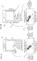
- Figs. 2A and 2B are schematic diagrams of the character input device according to the first embodiment of the present invention.
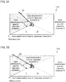
- Figs. 3A and 3B are schematic diagrams describing the adjustment of the input determination areas for the character input device according to the first embodiment of the present invention.
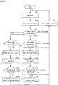
- Fig. 4 is a flowchart showing the operation of the character input device according to the first embodiment of the present invention.
- the character input device 10 includes the operation unit 110 and the character output unit 160.
- Fig. 2A is a schematic diagram of the character input device 10 operated with one hand, including an enlarged view of the operation unit 110.
- Fig. 2B is a schematic diagram of the character input device 10 operated with both hands, including an enlarged view of the operation unit 110.
- a user inputs a Japanese character I as a first input character with a thumb.
- the digit detector 140 detects the input with the thumb.
- a first input path of the thumb extends along a path D1.
- the path D1 is included in an input determination area defined for the Japanese character U.
- the Japanese character U is output to the character output unit 160.
- the user determines the Japanese character U as an input error, and presses a delete button.
- the user then inputs a Japanese character I, which is a second input character, along a second input path.
- the controller 130 determines that the user intends to input the Japanese character I, which is the second input character, with the first input path.
- the controller 130 associates the first input path with the Japanese character I, which is the second input character, and stores the information into the storage 150.
- the user then inputs the Japanese character I, which is a third input character, with a forefinger (a digit other than a thumb).
- the digit detector 140 detects the input with a forefinger.
- the third input path of the forefinger extends along the path D2.
- the path D2 is included in the input determination area defined for the Japanese character U.
- the Japanese character U is output to the character output unit 160.
- the user determines the Japanese character U as an input error, and presses the delete button.
- the user then inputs a Japanese character I, which is a fourth input character, along a fourth input path.
- the controller 130 determines that the user intends to input the Japanese character I, which is the fourth input character, with the third input path.
- the controller 130 associates the third input path with the Japanese character I, which is the fourth input character, and stores the information into the storage 150.
- the controller 130 repeats the above operations to adjust the input determination areas for the second input character and the fourth input character. This structure thus improves user convenience.
- Fig. 3A is an enlarged view of the input determination areas in the example of Fig. 2A .
- Fig. 3B is an enlarged view of the input determination areas in the example of Fig. 2B .
- Figs. 3A and 3B show the results obtained after multiple input errors.
- the input determination area for the Japanese character I is defined with a reference line and the path D1, which is the first input path.
- the reference line passing through the center of the operation unit 110 and the path D1 form the angle ⁇ 1 between them.
- This first input path may be the mean of the first input paths of multiple input errors of the user, or may be the mean of the first input paths of input errors of the user made before the input error count reaches a threshold.
- the input determination area for the Japanese character I is defined with the reference line and the path D2, which is the third input path.
- the reference line passing through the operation unit 110 and the path D2 form the angle ⁇ 2 between them.
- the third input path may be the mean of the third input paths of multiple input errors of the user, or may be the mean of the third input paths of input errors of the user made before the input error count reaches a threshold.
- the angle ⁇ 1 is greater than the angle ⁇ 2. More specifically, the input with a thumb in Fig. 3A is more likely to cause an input error. However, the controller 130 can determine the input error tendency and the habitual input tendency of the user, and adjust the input determination areas for the thumb or for a digit other than the thumb.
- Fig. 4 is a flowchart showing the operation of the character input device according to the first embodiment of the present invention.
- the user performs key entry (flick input) by operating the operation unit 110.
- the operation detector 120 detects the key entry information and outputs the information to the controller 130 (S101).
- the controller 130 stores the key entry information into the storage 150 (S102).
- the digit detector 140 determines the digit used for the key entry (S103). When the digit detector 140 determines that the digit used for the key entry is a thumb, the operation detector 120 determines whether the delete key is pressed subsequently (S104).
- the operation detector 120 determines that the delete key has been pressed (Yes in S104)
- the input information (first input character) is read from the storage 150 (S105).
- the operation detector 120 determines that the delete key has not been pressed (No in S104)
- the input information is deleted (S121).
- the controller 130 compares the first input character with the second input character. When the first input character differs from the second input character, the input error count is incremented by one.
- the controller 130 determines whether the input error count reaches a predetermined number (threshold) (S107). When the input error count has reached the predetermined number (Yes in S107), the controller 130 changes and updates the input determination areas for the thumb (S108). When the input error count has not reached the predetermined number (No in S107), the controller 130 deletes the input information (S121).
- the operation detector 120 determines whether the delete key is pressed (S114).
- the operation detector 120 determines that the delete key has been pressed (Yes in S114)
- the input information (third input character) is read from the storage 150 (S115).
- the operation detector 120 determines that the delete key has not been pressed (No in S114)
- the input information is deleted (S121).
- the controller 130 compares the third input character with the fourth input character. When the third input character differs from the fourth input character, the input error count is incremented by one.
- the controller 130 determines whether the input error count reaches a predetermined number (threshold) (S117). When the input error count has reached the predetermined number (Yes in S117), the controller 130 changes and updates the input determination areas for the thumb (S118). When the input error count has not reached the predetermined number (No in S117), the controller 130 deletes the input information (S121).
- the digit used for the flick input is determined to be either a thumb or a digit other than a thumb, and the input determination areas for each digit can be updated. Input errors with a thumb or with a digit other than a thumb can also be detected, and the input determination areas can be updated accordingly.
- This structure also determines the input tendency of the user, and improves user convenience.
- Input errors can be detected based on a predetermined count (threshold), which can be determined in advance. This allows more flexible setting.
- Each input determination area may be sized to prevent another input determination area for a different character on the software keyboard from becoming too small.
- FIG. 5 is a flowchart showing the operation of a character input device according to a second embodiment of the present invention.
- the second embodiment differs from the first embodiment in the procedure for adjusting the input determination areas.
- the other components and processes are the same as those in the first embodiment, and will not be described.
- a user performs an input on the operation unit 110.
- the operation detector 120 detects the input information, and outputs the information to the controller 130 (S201).
- the controller 130 stores the input information into the storage 150 (S202).
- the digit detector 140 determines the digit used for key entry (S203). When the digit detector 140 determines that the digit used for the key entry is a thumb, correct information prestored for a thumb is read from the storage 150 (S204). The correct information is to be used for updating the input determination areas.
- the controller 130 stores the input information into the storage 150 (S205).
- the operation detector 120 determines whether the delete key is pressed (S206).
- the operation detector 120 determines that the delete key has been pressed (Yes in S206)
- the input information (the first input character) is read from the storage 150 (S207).
- the operation detector 120 determines that the delete key has not been pressed (No in S206)
- the input information is deleted (S221).
- the controller 130 compares the first input character with the second input character. When the first input character differs from the second input character, the input error count is incremented by one.
- the controller 130 determines whether the input error count reaches a predetermined number (threshold) (S209). When the input error count has reached the predetermined number (Yes in S209), the controller 130 changes and updates the input determination areas for the thumb with a mean value calculated using the correct information (S210). The correct information is then updated accordingly. When the input error count has not reached the predetermined number (No in S209), the controller 130 deletes the input information (S221).
- the controller 130 stores the input information into the storage 150 (S215).
- the operation detector 120 determines whether the delete key is pressed (S216).
- the operation detector 120 determines that the delete key has been pressed (Yes in S216)
- the input information (the third input character) is read from the storage 150 (S217).
- the operation detector 120 determines that the delete key has not been pressed (No in S216)
- the input information is deleted (S221).
- the user performs key entry again with the operation unit 110 (S218).
- the controller 130 compares the third input character with the fourth input character. When the third input character differs from the fourth input character, the input error count is incremented by one.
- the controller 130 determines whether the input error count reaches a predetermined number (threshold) (S219). When the input error count has reached the predetermined number (Yes in S219), the controller 130 changes and updates the input determination areas for the thumb with the mean value calculated using the correct information (S220). The correct information is then updated accordingly. When the input error count has not reached the predetermined number (No in S219), the controller 130 deletes the input information (S221).
- the digit used for the flick input is determined to be either a thumb or a digit other than a thumb, and the input determination areas for each digit can be updated accordingly.
- the prestored correct information allows such input determination in accordance with the types of digit even after the device is reactivated and the key entry is restarted.
- Input errors with a thumb or a digit other than a thumb can also be detected, and the input determination areas can be updated accordingly.
- This structure also determines the input tendency of the user, and improves usability for the user.
- Input errors can be detected based on a predetermined count (threshold) determined in advance. This allows more flexible setting.
- the structures described above may retain predictive suggestions or the input mode for each type of digit. Such predictive suggestions or key entry settings may then be switched depending on whether the digit used for key entry is a thumb or a digit other than a thumb.
Landscapes
- Engineering & Computer Science (AREA)
- General Engineering & Computer Science (AREA)
- Theoretical Computer Science (AREA)
- Human Computer Interaction (AREA)
- Physics & Mathematics (AREA)
- General Physics & Mathematics (AREA)
- User Interface Of Digital Computer (AREA)
- Input From Keyboards Or The Like (AREA)
- Telephone Function (AREA)
Abstract
Description
- This application claims priority to Japanese Patent Application No.
2018-038658 filed on March 5, 2018 - The present invention relates to a technique for inputting characters on a touchscreen input device.
-
Patent Literature 1 describes a technique for detecting an input error made by a user in an input operation including a sliding operation and correcting the input error. - Patent Literature 1:
WO 2012/161223 - However, the structure described in
Patent Literature 1 does not determine which digit (thumb or finger) is used for a sliding operation, and thus can further cause an input error in an input operation performed with a different digit. - One or more aspects of the present invention are directed to a technique for reducing errors in input operations performed with different digits.
- A character input device according to one aspect of present invention includes an operation unit that receives a character input performed with a flick input, a digit detector that determines a type of digit used for the flick input, and a controller that adjusts an input determination area for the character input in accordance with an input error count for the flick input.
- This structure adjusts the input determination area for each type of digit used in every flick input to reduce input errors, and thus improves user convenience.
- The character input device may further include a storage that stores the type of digit in a manner associated with the input error count for the flick input.
- This structure stores the input determination area for each type of digit for subsequent operations.
- The controller included in the character input device may set a threshold on the input error count for the flick input, and may adjust the input determination area when the count exceeds the threshold.
- This structure efficiently adjusts the input determination area.
- The type of digit used in the character input device includes a thumb and a digit other than the thumb.
- This structure distinguishes a thumb that moves differently in an input operation from other digits to adjust the input determination area as appropriate for each situation.
- The technique according to the above aspects reduces input errors in a sliding operation.
-
-
Fig. 1 is a block diagram of a character input device according to a first embodiment of the present invention. -
Figs. 2A and 2B are schematic diagrams of the character input device according to the first embodiment of the present invention. -
Figs. 3A and 3B are schematic diagrams of adjusting input determination areas for the character input device according to the first embodiment of the present invention. -
Fig. 4 is a flowchart showing the operation of the character input device according to the first embodiment of the present invention. -
Fig. 5 is a flowchart showing the operation of a character input device according to a second embodiment of the present invention. - Embodiments of the present invention will now be described with reference to the drawings.
- An example of the present invention will be described first with reference to
Fig. 1. Fig. 1 is a block diagram of a character input device according to a first embodiment of the present invention. Acharacter input device 10 is installed in, for example, a mobile communication terminal such as a smartphone, and allows a user to input characters by performing an operation on a touchscreen display. - The
character input device 10 includes anoperation unit 110, anoperation detector 120, acontroller 130, adigit detector 140, astorage 150, and acharacter output unit 160. Character inputs (described below) include flick inputs with digits. A flick input refers to inputting characters by sliding on a touchscreen display. A flick input described in the example below inputs Japanese characters, but the same technique is applicable to inputting alphabetical characters. - An input with a thumb will be described first.
- The
operation unit 110 is, for example, a software keyboard on a touchscreen display that displays keys and receives character inputs. Theoperation unit 110 includes multiple input determination areas. - The
operation detector 120 detects a character input on theoperation unit 110, and outputs a path of the character input (hereafter, a first input path) and a first character input (hereafter, a first input character) to thecontroller 130. - The
controller 130 outputs the first input path to thedigit detector 140. Based on the first input path, thedigit detector 140 detects an input with a thumb through predetermined determination using, for example, the path length of the character input or the size of the area over which the digit touches during the character input. - The
controller 130 outputs the first input character to thecharacter output unit 160. The user views and recognizes the first input character on thecharacter output unit 160. - When determining that the first input character has an input error, the user presses a delete button to delete the first input character.
- The user then inputs a correct character (hereafter, a second input character). The
operation unit 110 receives the character input of the second input character. - The
operation detector 120 detects the character input on theoperation unit 110, and outputs a path of the character input (hereafter, a second input path) and the second input character to thecontroller 130. - The
controller 130 compares the first input character with the second input character. Thecontroller 130 determines that the user has made an input error when the second input character differs from the first input character. Thecontroller 130 associates the first input path with the second character input, and stores the information into thestorage 150. - The
controller 130 repeats the above operations to count the number of input errors. The input error count for the user with a thumb is stored into thestorage 150. - The
controller 130 thus determines the tendency of input errors with a thumb. For example, thecontroller 130 calculates the mean value of the first input paths, and corrects the input determination areas for the second input character. The input determination areas are used to determine the character to be selectively input by thecontroller 130 in response to up/down or right/left sliding in a flick input. - This structure corrects the input determination areas for an input with a thumb, and improves user convenience.
- An input with a digit other than a thumb, or for example with a forefinger, will now be described.
- The
operation detector 120 detects a character input on theoperation unit 110, and outputs a path of the character input (hereafter, a third input path) and a first character input (hereafter, a third input character) to thecontroller 130. - The
controller 130 outputs the third input path to thedigit detector 140. Based on the path, thedigit detector 140 detects an input with a digit other than a thumb through predetermined determination. - The
controller 130 outputs the third input character to thecharacter output unit 160. The user views and recognizes the third input character on thecharacter output unit 160. - When determining that the third input character has an input error, the user deletes the third input character.
- The user then inputs a correct character (hereafter, a fourth input character). The
operation unit 110 receives the character input of the fourth input character. - The
operation detector 120 detects the character input on theoperation unit 110, and outputs a path of the character input (hereafter, a fourth input path) and the fourth input character to thecontroller 130. - In the same manner as for the input with a thumb, the
controller 130 compares the third input character with the fourth input character. Thecontroller 130 determines that the user has made an input error when the fourth input character differs from the third input character. Thecontroller 130 associates the third input path with the fourth character input, and stores the information into thestorage 150. - The
controller 130 repeats the above operations to count the input error count. The input error count for the user with a forefinger (a digit other than a thumb) is stored into thestorage 150. - The
controller 130 thus determines the tendency of input errors with a forefinger (a digit other than a thumb). As described above, thecontroller 130 calculates the mean value of the third input paths, and corrects the input determination areas for the fourth input character. - This structure corrects the input determination areas for an input with a forefinger (a digit other than a thumb), and improves user convenience.
- This structure thus determines whether an input is performed with a thumb or a digit other than a thumb, and corrects the input determination areas accordingly.
-
Fig. 1 is a block diagram of a character input device according to the first embodiment of the present invention.Figs. 2A and 2B are schematic diagrams of the character input device according to the first embodiment of the present invention.Figs. 3A and 3B are schematic diagrams describing the adjustment of the input determination areas for the character input device according to the first embodiment of the present invention.Fig. 4 is a flowchart showing the operation of the character input device according to the first embodiment of the present invention. - An example structure will be described in more detail with reference to
Figs. 2A and 2B based on the structure of thecharacter input device 10 shown inFig. 1 . - As shown in
Figs. 1 ,2A, and 2B , thecharacter input device 10 includes theoperation unit 110 and thecharacter output unit 160. -
Fig. 2A is a schematic diagram of thecharacter input device 10 operated with one hand, including an enlarged view of theoperation unit 110. Similarly,Fig. 2B is a schematic diagram of thecharacter input device 10 operated with both hands, including an enlarged view of theoperation unit 110. - As shown in
Fig. 2A , a user inputs a Japanese character I as a first input character with a thumb. Thedigit detector 140 detects the input with the thumb. - A first input path of the thumb extends along a path D1. The path D1 is included in an input determination area defined for the Japanese character U. In this case, the Japanese character U is output to the
character output unit 160. - The user thus determines the Japanese character U as an input error, and presses a delete button. The user then inputs a Japanese character I, which is a second input character, along a second input path.
- The
controller 130 determines that the user intends to input the Japanese character I, which is the second input character, with the first input path. Thecontroller 130 associates the first input path with the Japanese character I, which is the second input character, and stores the information into thestorage 150. - As shown in
Fig. 2B , the user then inputs the Japanese character I, which is a third input character, with a forefinger (a digit other than a thumb). Thedigit detector 140 detects the input with a forefinger. - As in the example shown in
Fig. 2A , the third input path of the forefinger extends along the path D2. The path D2 is included in the input determination area defined for the Japanese character U. In this case, the Japanese character U is output to thecharacter output unit 160. - The user thus determines the Japanese character U as an input error, and presses the delete button. The user then inputs a Japanese character I, which is a fourth input character, along a fourth input path.
- The
controller 130 determines that the user intends to input the Japanese character I, which is the fourth input character, with the third input path. Thecontroller 130 associates the third input path with the Japanese character I, which is the fourth input character, and stores the information into thestorage 150. - The
controller 130 repeats the above operations to adjust the input determination areas for the second input character and the fourth input character. This structure thus improves user convenience. - A method for adjusting the input determination areas will be described in more detail with reference to
Figs. 3A and 3B . -
Fig. 3A is an enlarged view of the input determination areas in the example ofFig. 2A .Fig. 3B is an enlarged view of the input determination areas in the example ofFig. 2B .Figs. 3A and 3B show the results obtained after multiple input errors. - For the input with a thumb, as shown in
Fig. 3A , the input determination area for the Japanese character I is defined with a reference line and the path D1, which is the first input path. The reference line passing through the center of theoperation unit 110 and the path D1 form the angle θ1 between them. - This first input path may be the mean of the first input paths of multiple input errors of the user, or may be the mean of the first input paths of input errors of the user made before the input error count reaches a threshold.
- For the input with a digit other than a thumb, as shown in
Fig. 3B , the input determination area for the Japanese character I is defined with the reference line and the path D2, which is the third input path. The reference line passing through theoperation unit 110 and the path D2 form the angle θ2 between them. - In the same manner as the first input path, the third input path may be the mean of the third input paths of multiple input errors of the user, or may be the mean of the third input paths of input errors of the user made before the input error count reaches a threshold.
- As shown in
Figs. 3A and 3B , the angle θ1 is greater than the angle θ2. More specifically, the input with a thumb inFig. 3A is more likely to cause an input error. However, thecontroller 130 can determine the input error tendency and the habitual input tendency of the user, and adjust the input determination areas for the thumb or for a digit other than the thumb. - An operation for adjusting the input determination areas will be described in detail with reference to
Fig. 4. Fig. 4 is a flowchart showing the operation of the character input device according to the first embodiment of the present invention. - The user performs key entry (flick input) by operating the
operation unit 110. Theoperation detector 120 detects the key entry information and outputs the information to the controller 130 (S101). - The
controller 130 stores the key entry information into the storage 150 (S102). - The
digit detector 140 determines the digit used for the key entry (S103). When thedigit detector 140 determines that the digit used for the key entry is a thumb, theoperation detector 120 determines whether the delete key is pressed subsequently (S104). - When the
operation detector 120 determines that the delete key has been pressed (Yes in S104), the input information (first input character) is read from the storage 150 (S105). When theoperation detector 120 determines that the delete key has not been pressed (No in S104), the input information is deleted (S121). - The user performs the key entry again with the operation unit 110 (S106). The
controller 130 compares the first input character with the second input character. When the first input character differs from the second input character, the input error count is incremented by one. - The
controller 130 determines whether the input error count reaches a predetermined number (threshold) (S107). When the input error count has reached the predetermined number (Yes in S107), thecontroller 130 changes and updates the input determination areas for the thumb (S108). When the input error count has not reached the predetermined number (No in S107), thecontroller 130 deletes the input information (S121). - When the
digit detector 140 determines that the digit used for the key entry is a digit other than a thumb, theoperation detector 120 determines whether the delete key is pressed (S114). - When the
operation detector 120 determines that the delete key has been pressed (Yes in S114), the input information (third input character) is read from the storage 150 (S115). When theoperation detector 120 determines that the delete key has not been pressed (No in S114), the input information is deleted (S121). - The user performs the key entry again with the operation unit 110 (S116). The
controller 130 compares the third input character with the fourth input character. When the third input character differs from the fourth input character, the input error count is incremented by one. - The
controller 130 determines whether the input error count reaches a predetermined number (threshold) (S117). When the input error count has reached the predetermined number (Yes in S117), thecontroller 130 changes and updates the input determination areas for the thumb (S118). When the input error count has not reached the predetermined number (No in S117), thecontroller 130 deletes the input information (S121). - When the digit for the input is not determined (S103), the input information is deleted (S121).
- With the above procedure, the digit used for the flick input is determined to be either a thumb or a digit other than a thumb, and the input determination areas for each digit can be updated. Input errors with a thumb or with a digit other than a thumb can also be detected, and the input determination areas can be updated accordingly. This structure also determines the input tendency of the user, and improves user convenience.
- Input errors can be detected based on a predetermined count (threshold), which can be determined in advance. This allows more flexible setting.
- Each input determination area may be sized to prevent another input determination area for a different character on the software keyboard from becoming too small.
- An operation for adjusting the input determination areas will now be described in detail with reference to
Fig. 5. Fig. 5 is a flowchart showing the operation of a character input device according to a second embodiment of the present invention. - The second embodiment differs from the first embodiment in the procedure for adjusting the input determination areas. The other components and processes are the same as those in the first embodiment, and will not be described.
- A user performs an input on the
operation unit 110. Theoperation detector 120 detects the input information, and outputs the information to the controller 130 (S201). - The
controller 130 stores the input information into the storage 150 (S202). - The
digit detector 140 determines the digit used for key entry (S203). When thedigit detector 140 determines that the digit used for the key entry is a thumb, correct information prestored for a thumb is read from the storage 150 (S204). The correct information is to be used for updating the input determination areas. - The
controller 130 stores the input information into the storage 150 (S205). - The
operation detector 120 determines whether the delete key is pressed (S206). - When the
operation detector 120 determines that the delete key has been pressed (Yes in S206), the input information (the first input character) is read from the storage 150 (S207). When theoperation detector 120 determines that the delete key has not been pressed (No in S206), the input information is deleted (S221). - The user performs the key entry again with the operation unit 110 (S208). The
controller 130 compares the first input character with the second input character. When the first input character differs from the second input character, the input error count is incremented by one. - The
controller 130 determines whether the input error count reaches a predetermined number (threshold) (S209). When the input error count has reached the predetermined number (Yes in S209), thecontroller 130 changes and updates the input determination areas for the thumb with a mean value calculated using the correct information (S210). The correct information is then updated accordingly. When the input error count has not reached the predetermined number (No in S209), thecontroller 130 deletes the input information (S221). - When the
digit detector 140 determines that the digit used for the key entry is a digit other than a thumb, correct information prestored for a digit other than a thumb is read from the storage 150 (S214). - The
controller 130 stores the input information into the storage 150 (S215). - The
operation detector 120 determines whether the delete key is pressed (S216). - When the
operation detector 120 determines that the delete key has been pressed (Yes in S216), the input information (the third input character) is read from the storage 150 (S217). When theoperation detector 120 determines that the delete key has not been pressed (No in S216), the input information is deleted (S221). - The user performs key entry again with the operation unit 110 (S218). The
controller 130 compares the third input character with the fourth input character. When the third input character differs from the fourth input character, the input error count is incremented by one. - The
controller 130 determines whether the input error count reaches a predetermined number (threshold) (S219). When the input error count has reached the predetermined number (Yes in S219), thecontroller 130 changes and updates the input determination areas for the thumb with the mean value calculated using the correct information (S220). The correct information is then updated accordingly. When the input error count has not reached the predetermined number (No in S219), thecontroller 130 deletes the input information (S221). - When the digit for the input is not determined (S103), the input information is deleted (S121).
- With the above procedure as well, the digit used for the flick input is determined to be either a thumb or a digit other than a thumb, and the input determination areas for each digit can be updated accordingly.
- The prestored correct information allows such input determination in accordance with the types of digit even after the device is reactivated and the key entry is restarted.
- Input errors with a thumb or a digit other than a thumb can also be detected, and the input determination areas can be updated accordingly. This structure also determines the input tendency of the user, and improves usability for the user.
- Input errors can be detected based on a predetermined count (threshold) determined in advance. This allows more flexible setting.
- The structures described above may retain predictive suggestions or the input mode for each type of digit. Such predictive suggestions or key entry settings may then be switched depending on whether the digit used for key entry is a thumb or a digit other than a thumb.
-
- D1, D2
- path
- 10
- character input device
- 110
- operation unit
- 120
- operation detector
- 130
- controller
- 140
- digit detector
- 150
- storage
- 160
- character output unit
Claims (6)
- A character input device (10), comprising:an operation unit (110) configured to receive a character input performed with a flick input;a digit detector (140) configured to determine a type of digit used for the flick input; anda controller (130) configured to adjust an input determination area for the character input in accordance with an input error count for the flick input.
- The character input device (10) according to claim 1, further comprising:
a storage (150) configured to store the type of digit in a manner associated with the input error count for the flick input. - The character input device (10) according to claim 1 or claim 2, wherein
the controller (130) sets a threshold for the input error count for the flick input, and adjusts the input determination area when the count exceeds the threshold. - The character input device (10) according to any one of claims 1 to 3, wherein
the type of digit includes a thumb and a digit other than the thumb. - A character input method implemented by a computer, the method comprising:receiving a character input performed with a flick input;determining a type of digit used for the flick input; andadjusting an input determination area for the character input in accordance with an input error count for the flick input.
- A character input program executable by a computer, the program comprising:receiving a character input performed with a flick input;determining a type of digit used for the flick input; andadjusting an input determination area for the character input in accordance with an input error count for the flick input.
Applications Claiming Priority (1)
| Application Number | Priority Date | Filing Date | Title |
|---|---|---|---|
| JP2018038658A JP7124345B2 (en) | 2018-03-05 | 2018-03-05 | Character input device, character input method, and character input program |
Publications (2)
| Publication Number | Publication Date |
|---|---|
| EP3537262A1 true EP3537262A1 (en) | 2019-09-11 |
| EP3537262B1 EP3537262B1 (en) | 2023-08-16 |
Family
ID=65576111
Family Applications (1)
| Application Number | Title | Priority Date | Filing Date |
|---|---|---|---|
| EP19156441.8A Active EP3537262B1 (en) | 2018-03-05 | 2019-02-11 | Character input device, character input method, and character input program |
Country Status (3)
| Country | Link |
|---|---|
| US (1) | US20190272061A1 (en) |
| EP (1) | EP3537262B1 (en) |
| JP (1) | JP7124345B2 (en) |
Families Citing this family (1)
| Publication number | Priority date | Publication date | Assignee | Title |
|---|---|---|---|---|
| JP7143792B2 (en) * | 2019-03-14 | 2022-09-29 | オムロン株式会社 | Character input device, character input method, and character input program |
Citations (2)
| Publication number | Priority date | Publication date | Assignee | Title |
|---|---|---|---|---|
| WO2012161223A1 (en) | 2011-05-25 | 2012-11-29 | Necカシオモバイルコミュニケーションズ株式会社 | Input device, input method, and program |
| US20140055371A1 (en) * | 2012-08-24 | 2014-02-27 | Nokia Corporation | Methods, apparatuses, and computer program products for determination of the digit being used by a user to provide input |
Family Cites Families (3)
| Publication number | Priority date | Publication date | Assignee | Title |
|---|---|---|---|---|
| JP2012203653A (en) | 2011-03-25 | 2012-10-22 | Ntt Docomo Inc | Information terminal, display control method, and display control program |
| JP6085529B2 (en) | 2013-06-18 | 2017-02-22 | シャープ株式会社 | Character input device |
| JP2016218963A (en) * | 2015-05-26 | 2016-12-22 | 富士通株式会社 | Information processing apparatus, input control program, and input control method |
-
2018
- 2018-03-05 JP JP2018038658A patent/JP7124345B2/en active Active
-
2019
- 2019-02-11 EP EP19156441.8A patent/EP3537262B1/en active Active
- 2019-02-21 US US16/281,610 patent/US20190272061A1/en not_active Abandoned
Patent Citations (3)
| Publication number | Priority date | Publication date | Assignee | Title |
|---|---|---|---|---|
| WO2012161223A1 (en) | 2011-05-25 | 2012-11-29 | Necカシオモバイルコミュニケーションズ株式会社 | Input device, input method, and program |
| US20140333549A1 (en) * | 2011-05-25 | 2014-11-13 | Nec Casio Mobile Communications, Ltd. | Input device, input method, and program |
| US20140055371A1 (en) * | 2012-08-24 | 2014-02-27 | Nokia Corporation | Methods, apparatuses, and computer program products for determination of the digit being used by a user to provide input |
Also Published As
| Publication number | Publication date |
|---|---|
| JP2019153142A (en) | 2019-09-12 |
| EP3537262B1 (en) | 2023-08-16 |
| JP7124345B2 (en) | 2022-08-24 |
| US20190272061A1 (en) | 2019-09-05 |
Similar Documents
| Publication | Publication Date | Title |
|---|---|---|
| EP3245580B1 (en) | Unlearning techniques for adaptive language models in text entry | |
| US10019435B2 (en) | Space prediction for text input | |
| US9508028B2 (en) | Converting text strings into number strings, such as via a touchscreen input | |
| US9377871B2 (en) | System and methods for determining keyboard input in the presence of multiple contact points | |
| CN101788855B (en) | Method, device and communication terminal for obtaining user input information | |
| US20130021256A1 (en) | Mobile terminal with touch panel function and input method for same | |
| US20130346904A1 (en) | Targeted key press zones on an interactive display | |
| US20120023433A1 (en) | Method and apparatus for inputting character in a portable terminal | |
| CN107340880A (en) | A kind of association-feeding method, device and the electronic equipment for realizing association's input | |
| WO2014161295A1 (en) | Device and method for adaptively adjusting layout of touch input panel, and mobile terminal | |
| CN104808943A (en) | Input implementation method, input implementation device and portable terminal of virtual keyboard | |
| CN105892927A (en) | Mobile terminal control method and device | |
| CN105700782A (en) | Method for regulating virtual key layout, device for regulating virtual key layout and mobile terminal | |
| US20120319958A1 (en) | Portable information terminal and key arrangement alteration method therefor | |
| US8525792B1 (en) | Adjustable keyboard or touch screen in a handheld device | |
| EP3537262B1 (en) | Character input device, character input method, and character input program | |
| WO2010024416A1 (en) | Display apparatus and display method thereof | |
| JP5455343B2 (en) | Input device | |
| CN105589570A (en) | Input error processing method and apparatus | |
| US9335833B2 (en) | Keyboard input control method and system | |
| EP3709136A1 (en) | Character input device, character input method, and character input program | |
| CN109426354B (en) | Input method, device and device for input | |
| CN113190125B (en) | Input correction method and device | |
| US11347377B2 (en) | Character input device, character input method, and character input program | |
| US20140362005A1 (en) | Information terminal device, key correction method, and recording medium |
Legal Events
| Date | Code | Title | Description |
|---|---|---|---|
| PUAI | Public reference made under article 153(3) epc to a published international application that has entered the european phase |
Free format text: ORIGINAL CODE: 0009012 |
|
| STAA | Information on the status of an ep patent application or granted ep patent |
Free format text: STATUS: REQUEST FOR EXAMINATION WAS MADE |
|
| 17P | Request for examination filed |
Effective date: 20190226 |
|
| AK | Designated contracting states |
Kind code of ref document: A1 Designated state(s): AL AT BE BG CH CY CZ DE DK EE ES FI FR GB GR HR HU IE IS IT LI LT LU LV MC MK MT NL NO PL PT RO RS SE SI SK SM TR |
|
| AX | Request for extension of the european patent |
Extension state: BA ME |
|
| RBV | Designated contracting states (corrected) |
Designated state(s): AL AT BE BG CH CY CZ DE DK EE ES FI FR GB GR HR HU IE IS IT LI LT LU LV MC MK MT NL NO PL PT RO RS SE SI SK SM TR |
|
| STAA | Information on the status of an ep patent application or granted ep patent |
Free format text: STATUS: EXAMINATION IS IN PROGRESS |
|
| 17Q | First examination report despatched |
Effective date: 20210520 |
|
| GRAP | Despatch of communication of intention to grant a patent |
Free format text: ORIGINAL CODE: EPIDOSNIGR1 |
|
| STAA | Information on the status of an ep patent application or granted ep patent |
Free format text: STATUS: GRANT OF PATENT IS INTENDED |
|
| INTG | Intention to grant announced |
Effective date: 20230228 |
|
| RAP3 | Party data changed (applicant data changed or rights of an application transferred) |
Owner name: OMRON CORPORATION |
|
| GRAS | Grant fee paid |
Free format text: ORIGINAL CODE: EPIDOSNIGR3 |
|
| GRAA | (expected) grant |
Free format text: ORIGINAL CODE: 0009210 |
|
| STAA | Information on the status of an ep patent application or granted ep patent |
Free format text: STATUS: THE PATENT HAS BEEN GRANTED |
|
| AK | Designated contracting states |
Kind code of ref document: B1 Designated state(s): AL AT BE BG CH CY CZ DE DK EE ES FI FR GB GR HR HU IE IS IT LI LT LU LV MC MK MT NL NO PL PT RO RS SE SI SK SM TR |
|
| REG | Reference to a national code |
Ref country code: CH Ref legal event code: EP |
|
| REG | Reference to a national code |
Ref country code: DE Ref legal event code: R096 Ref document number: 602019034924 Country of ref document: DE |
|
| REG | Reference to a national code |
Ref country code: IE Ref legal event code: FG4D |
|
| REG | Reference to a national code |
Ref country code: LT Ref legal event code: MG9D |
|
| REG | Reference to a national code |
Ref country code: NL Ref legal event code: MP Effective date: 20230816 |
|
| REG | Reference to a national code |
Ref country code: AT Ref legal event code: MK05 Ref document number: 1600692 Country of ref document: AT Kind code of ref document: T Effective date: 20230816 |
|
| PG25 | Lapsed in a contracting state [announced via postgrant information from national office to epo] |
Ref country code: GR Free format text: LAPSE BECAUSE OF FAILURE TO SUBMIT A TRANSLATION OF THE DESCRIPTION OR TO PAY THE FEE WITHIN THE PRESCRIBED TIME-LIMIT Effective date: 20231117 |
|
| PG25 | Lapsed in a contracting state [announced via postgrant information from national office to epo] |
Ref country code: IS Free format text: LAPSE BECAUSE OF FAILURE TO SUBMIT A TRANSLATION OF THE DESCRIPTION OR TO PAY THE FEE WITHIN THE PRESCRIBED TIME-LIMIT Effective date: 20231216 |
|
| PG25 | Lapsed in a contracting state [announced via postgrant information from national office to epo] |
Ref country code: SE Free format text: LAPSE BECAUSE OF FAILURE TO SUBMIT A TRANSLATION OF THE DESCRIPTION OR TO PAY THE FEE WITHIN THE PRESCRIBED TIME-LIMIT Effective date: 20230816 Ref country code: RS Free format text: LAPSE BECAUSE OF FAILURE TO SUBMIT A TRANSLATION OF THE DESCRIPTION OR TO PAY THE FEE WITHIN THE PRESCRIBED TIME-LIMIT Effective date: 20230816 Ref country code: PT Free format text: LAPSE BECAUSE OF FAILURE TO SUBMIT A TRANSLATION OF THE DESCRIPTION OR TO PAY THE FEE WITHIN THE PRESCRIBED TIME-LIMIT Effective date: 20231218 Ref country code: NO Free format text: LAPSE BECAUSE OF FAILURE TO SUBMIT A TRANSLATION OF THE DESCRIPTION OR TO PAY THE FEE WITHIN THE PRESCRIBED TIME-LIMIT Effective date: 20231116 Ref country code: NL Free format text: LAPSE BECAUSE OF FAILURE TO SUBMIT A TRANSLATION OF THE DESCRIPTION OR TO PAY THE FEE WITHIN THE PRESCRIBED TIME-LIMIT Effective date: 20230816 Ref country code: LV Free format text: LAPSE BECAUSE OF FAILURE TO SUBMIT A TRANSLATION OF THE DESCRIPTION OR TO PAY THE FEE WITHIN THE PRESCRIBED TIME-LIMIT Effective date: 20230816 Ref country code: LT Free format text: LAPSE BECAUSE OF FAILURE TO SUBMIT A TRANSLATION OF THE DESCRIPTION OR TO PAY THE FEE WITHIN THE PRESCRIBED TIME-LIMIT Effective date: 20230816 Ref country code: IS Free format text: LAPSE BECAUSE OF FAILURE TO SUBMIT A TRANSLATION OF THE DESCRIPTION OR TO PAY THE FEE WITHIN THE PRESCRIBED TIME-LIMIT Effective date: 20231216 Ref country code: HR Free format text: LAPSE BECAUSE OF FAILURE TO SUBMIT A TRANSLATION OF THE DESCRIPTION OR TO PAY THE FEE WITHIN THE PRESCRIBED TIME-LIMIT Effective date: 20230816 Ref country code: GR Free format text: LAPSE BECAUSE OF FAILURE TO SUBMIT A TRANSLATION OF THE DESCRIPTION OR TO PAY THE FEE WITHIN THE PRESCRIBED TIME-LIMIT Effective date: 20231117 Ref country code: FI Free format text: LAPSE BECAUSE OF FAILURE TO SUBMIT A TRANSLATION OF THE DESCRIPTION OR TO PAY THE FEE WITHIN THE PRESCRIBED TIME-LIMIT Effective date: 20230816 Ref country code: AT Free format text: LAPSE BECAUSE OF FAILURE TO SUBMIT A TRANSLATION OF THE DESCRIPTION OR TO PAY THE FEE WITHIN THE PRESCRIBED TIME-LIMIT Effective date: 20230816 |
|
| PG25 | Lapsed in a contracting state [announced via postgrant information from national office to epo] |
Ref country code: PL Free format text: LAPSE BECAUSE OF FAILURE TO SUBMIT A TRANSLATION OF THE DESCRIPTION OR TO PAY THE FEE WITHIN THE PRESCRIBED TIME-LIMIT Effective date: 20230816 |
|
| PG25 | Lapsed in a contracting state [announced via postgrant information from national office to epo] |
Ref country code: ES Free format text: LAPSE BECAUSE OF FAILURE TO SUBMIT A TRANSLATION OF THE DESCRIPTION OR TO PAY THE FEE WITHIN THE PRESCRIBED TIME-LIMIT Effective date: 20230816 |
|
| PG25 | Lapsed in a contracting state [announced via postgrant information from national office to epo] |
Ref country code: SM Free format text: LAPSE BECAUSE OF FAILURE TO SUBMIT A TRANSLATION OF THE DESCRIPTION OR TO PAY THE FEE WITHIN THE PRESCRIBED TIME-LIMIT Effective date: 20230816 Ref country code: RO Free format text: LAPSE BECAUSE OF FAILURE TO SUBMIT A TRANSLATION OF THE DESCRIPTION OR TO PAY THE FEE WITHIN THE PRESCRIBED TIME-LIMIT Effective date: 20230816 Ref country code: ES Free format text: LAPSE BECAUSE OF FAILURE TO SUBMIT A TRANSLATION OF THE DESCRIPTION OR TO PAY THE FEE WITHIN THE PRESCRIBED TIME-LIMIT Effective date: 20230816 Ref country code: EE Free format text: LAPSE BECAUSE OF FAILURE TO SUBMIT A TRANSLATION OF THE DESCRIPTION OR TO PAY THE FEE WITHIN THE PRESCRIBED TIME-LIMIT Effective date: 20230816 Ref country code: DK Free format text: LAPSE BECAUSE OF FAILURE TO SUBMIT A TRANSLATION OF THE DESCRIPTION OR TO PAY THE FEE WITHIN THE PRESCRIBED TIME-LIMIT Effective date: 20230816 Ref country code: CZ Free format text: LAPSE BECAUSE OF FAILURE TO SUBMIT A TRANSLATION OF THE DESCRIPTION OR TO PAY THE FEE WITHIN THE PRESCRIBED TIME-LIMIT Effective date: 20230816 Ref country code: SK Free format text: LAPSE BECAUSE OF FAILURE TO SUBMIT A TRANSLATION OF THE DESCRIPTION OR TO PAY THE FEE WITHIN THE PRESCRIBED TIME-LIMIT Effective date: 20230816 |
|
| REG | Reference to a national code |
Ref country code: DE Ref legal event code: R097 Ref document number: 602019034924 Country of ref document: DE |
|
| PLBE | No opposition filed within time limit |
Free format text: ORIGINAL CODE: 0009261 |
|
| STAA | Information on the status of an ep patent application or granted ep patent |
Free format text: STATUS: NO OPPOSITION FILED WITHIN TIME LIMIT |
|
| 26N | No opposition filed |
Effective date: 20240517 |
|
| PG25 | Lapsed in a contracting state [announced via postgrant information from national office to epo] |
Ref country code: SI Free format text: LAPSE BECAUSE OF FAILURE TO SUBMIT A TRANSLATION OF THE DESCRIPTION OR TO PAY THE FEE WITHIN THE PRESCRIBED TIME-LIMIT Effective date: 20230816 |
|
| PG25 | Lapsed in a contracting state [announced via postgrant information from national office to epo] |
Ref country code: MC Free format text: LAPSE BECAUSE OF FAILURE TO SUBMIT A TRANSLATION OF THE DESCRIPTION OR TO PAY THE FEE WITHIN THE PRESCRIBED TIME-LIMIT Effective date: 20230816 |
|
| REG | Reference to a national code |
Ref country code: CH Ref legal event code: PL |
|
| PG25 | Lapsed in a contracting state [announced via postgrant information from national office to epo] |
Ref country code: LU Free format text: LAPSE BECAUSE OF NON-PAYMENT OF DUE FEES Effective date: 20240211 |
|
| PG25 | Lapsed in a contracting state [announced via postgrant information from national office to epo] |
Ref country code: CH Free format text: LAPSE BECAUSE OF NON-PAYMENT OF DUE FEES Effective date: 20240229 |
|
| PG25 | Lapsed in a contracting state [announced via postgrant information from national office to epo] |
Ref country code: LU Free format text: LAPSE BECAUSE OF NON-PAYMENT OF DUE FEES Effective date: 20240211 Ref country code: CH Free format text: LAPSE BECAUSE OF NON-PAYMENT OF DUE FEES Effective date: 20240229 |
|
| PG25 | Lapsed in a contracting state [announced via postgrant information from national office to epo] |
Ref country code: BG Free format text: LAPSE BECAUSE OF FAILURE TO SUBMIT A TRANSLATION OF THE DESCRIPTION OR TO PAY THE FEE WITHIN THE PRESCRIBED TIME-LIMIT Effective date: 20230816 |
|
| PG25 | Lapsed in a contracting state [announced via postgrant information from national office to epo] |
Ref country code: BG Free format text: LAPSE BECAUSE OF FAILURE TO SUBMIT A TRANSLATION OF THE DESCRIPTION OR TO PAY THE FEE WITHIN THE PRESCRIBED TIME-LIMIT Effective date: 20230816 |
|
| REG | Reference to a national code |
Ref country code: BE Ref legal event code: MM Effective date: 20240229 |
|
| PG25 | Lapsed in a contracting state [announced via postgrant information from national office to epo] |
Ref country code: BE Free format text: LAPSE BECAUSE OF NON-PAYMENT OF DUE FEES Effective date: 20240229 |
|
| PG25 | Lapsed in a contracting state [announced via postgrant information from national office to epo] |
Ref country code: IE Free format text: LAPSE BECAUSE OF NON-PAYMENT OF DUE FEES Effective date: 20240211 |
|
| PG25 | Lapsed in a contracting state [announced via postgrant information from national office to epo] |
Ref country code: IE Free format text: LAPSE BECAUSE OF NON-PAYMENT OF DUE FEES Effective date: 20240211 Ref country code: BE Free format text: LAPSE BECAUSE OF NON-PAYMENT OF DUE FEES Effective date: 20240229 |
|
| PG25 | Lapsed in a contracting state [announced via postgrant information from national office to epo] |
Ref country code: IT Free format text: LAPSE BECAUSE OF NON-PAYMENT OF DUE FEES Effective date: 20240211 |
|
| PG25 | Lapsed in a contracting state [announced via postgrant information from national office to epo] |
Ref country code: CY Free format text: LAPSE BECAUSE OF FAILURE TO SUBMIT A TRANSLATION OF THE DESCRIPTION OR TO PAY THE FEE WITHIN THE PRESCRIBED TIME-LIMIT; INVALID AB INITIO Effective date: 20190211 |
|
| PG25 | Lapsed in a contracting state [announced via postgrant information from national office to epo] |
Ref country code: HU Free format text: LAPSE BECAUSE OF FAILURE TO SUBMIT A TRANSLATION OF THE DESCRIPTION OR TO PAY THE FEE WITHIN THE PRESCRIBED TIME-LIMIT; INVALID AB INITIO Effective date: 20190211 |
|
| PG25 | Lapsed in a contracting state [announced via postgrant information from national office to epo] |
Ref country code: TR Free format text: LAPSE BECAUSE OF FAILURE TO SUBMIT A TRANSLATION OF THE DESCRIPTION OR TO PAY THE FEE WITHIN THE PRESCRIBED TIME-LIMIT Effective date: 20230816 |
|
| PGFP | Annual fee paid to national office [announced via postgrant information from national office to epo] |
Ref country code: GB Payment date: 20260219 Year of fee payment: 8 |
|
| PGFP | Annual fee paid to national office [announced via postgrant information from national office to epo] |
Ref country code: DE Payment date: 20260217 Year of fee payment: 8 |
|
| PGFP | Annual fee paid to national office [announced via postgrant information from national office to epo] |
Ref country code: FR Payment date: 20260219 Year of fee payment: 8 |