EP3537227B1 - Timepiece device for the display of the duration of day and night - Google Patents
Timepiece device for the display of the duration of day and night Download PDFInfo
- Publication number
- EP3537227B1 EP3537227B1 EP18159967.1A EP18159967A EP3537227B1 EP 3537227 B1 EP3537227 B1 EP 3537227B1 EP 18159967 A EP18159967 A EP 18159967A EP 3537227 B1 EP3537227 B1 EP 3537227B1
- Authority
- EP
- European Patent Office
- Prior art keywords
- latitude
- timepiece
- setting
- ring
- wheel
- Prior art date
- Legal status (The legal status is an assumption and is not a legal conclusion. Google has not performed a legal analysis and makes no representation as to the accuracy of the status listed.)
- Active
Links
- 230000005540 biological transmission Effects 0.000 claims description 31
- 210000000056 organ Anatomy 0.000 claims description 14
- 230000007246 mechanism Effects 0.000 description 6
- 241000112598 Pseudoblennius percoides Species 0.000 description 3
- 206010028980 Neoplasm Diseases 0.000 description 2
- 201000011510 cancer Diseases 0.000 description 2
- 241001481710 Cerambycidae Species 0.000 description 1
- 238000006073 displacement reaction Methods 0.000 description 1
- 238000004804 winding Methods 0.000 description 1
Images


Classifications
-
- G—PHYSICS
- G04—HOROLOGY
- G04B—MECHANICALLY-DRIVEN CLOCKS OR WATCHES; MECHANICAL PARTS OF CLOCKS OR WATCHES IN GENERAL; TIME PIECES USING THE POSITION OF THE SUN, MOON OR STARS
- G04B19/00—Indicating the time by visual means
- G04B19/26—Clocks or watches with indicators for tides, for the phases of the moon, or the like
- G04B19/262—Clocks or watches with indicators for tides, for the phases of the moon, or the like with indicators for astrological informations
Definitions
- the invention concerns a device, typically a timepiece device, indicating the duration of the day and the duration of the night.
- sunrise (or sunset) times are displayed by means of a mechanism palpating a cam whose shape takes into account latitude, longitude and UTC time, said cam expressing, at each point of its circumference, the value associated with the time of sunrise (or sunset) for a given day of the year.
- the mechanism described in patent CH690516 uses this type of cam.
- the cam is associated with a specific latitude. Therefore, the values indicated are no longer correct when the latitude changes. In order to change the latitude setting it would be necessary to change the shape of the cam.
- the patent application CH 712 374 A1 discloses a device indicating sunrise and sunset times at a given latitude using a different mechanism.
- the latitude is selected by the watchmaker when assembled. Therefore, like in the previously presented device, the user can not set the latitude whenever he wants, for example when he travels. Indeed, in order to modify the latitude setting, it is necessary to modify the assembly of the mechanism's organs.
- the invention aims at providing a timepiece device for displaying the duration of day and night that allows a correct display for every possible latitude.
- the invention proposes a timepiece device comprising a driving member, a transmission element and a display device, said driving member being intended to pivot about an axis at a speed of one revolution per year and comprising a latitude pin at a distance r from said axis and a latitude setting device for setting the value of the distance r, each value of r corresponding to a defined value of latitude and remains fixed once its setting has been made, said latitude pin cooperating with a means of cooperation of the transmission element for driving the latter in alternating movements, at least a part of the transmission element being guided in translation, the part of the transmission element being guided in translation comprising at least a first and a second portions kinematically connected respectively to a first and a second elements of the display device, said first and second elements being arranged to display the duration of the day and the duration of the night, said timepiece device comprising a control organ, said control organ typically comprising a latitude crown, for setting the latitude, and characterized in that in that said latitude
- the invention also proposes a timepiece, such as a pocket watch or a wristwatch, comprising a clockwork movement and such a timepiece device.
- night is defined as the time from dusk to dawn and “day” is defined as the time from dawn to dusk.
- figures 1 to 4 illustrate the display of a timepiece comprising a timepiece device 1 according to a particular embodiment of the invention.
- the timepiece of figure 1 comprises, among other things, a dial 30 comprising several indications 2, 5, 7, 10, hands 6, 8, 9 and a day/night display device which is a part of the timepiece device 1.
- the day/night display device comprises a first 3 and a second 4 day/night display elements arranged to display the duration of the day and the duration of the night.
- Said first 3 and second 4 display elements are intertwined cut rings, corresponding respectively to a night cut ring 3 and to a day cut ring 4.
- Both the night cut ring 3 and the day cut ring 4 have the shape of a dextral circular helix whose length is equal to one pitch, as shown in figure 5 but they could be longer.
- both the night cut ring 3 and the day cut ring 4 may have the shape of a sinister circular helix.
- Said cut rings 3, 4 are intertwined with the result of a visible night cut ring portion 3a and a visible day cut ring portion 4a.
- the lengths of said visible portions 3a, 4a depend on both the latitude and the day of the year, and respectively indicate the duration of the night and the duration of the day.
- the night cut ring 3 is dark in color, typically blue and the day cut ring 4 is light in color, typically yellow.
- said cut rings 3, 4, can be of any color from the moment they are visually distinguishable from each other.
- the cut rings 3, 4 are divided into hours sections, and respectively comprise indications of duration 3b, 4b corresponding to numbers from one to twenty-four. With these indications 3b, 4b, the duration of the day and the duration of night can easily be read on the cut rings 3, 4.
- the timepiece whose display is shown in figures 1 to 4 comprises a traditional hour scale comprising hour indexes 5 from one to twelve for the indication of the hour via a traditional hour hand 6.
- a traditional minute hand 9 makes it possible to read the minutes on graduations of the minutes 10 on the dial 30.
- Said timepiece also comprises an additional twenty-four hour scale comprising additional hour indexes 7.
- This scale make it possible to read the hours of sunrise and sunset times. Indeed, as shown in figures 1 to 4 , at the junctions of the two cut rings 3, 4, the hours of sunrise and sunset can be read on the twenty-four hour scale.
- the time can also be read on this twenty-four hour scale by means of an additional twenty-four hour hand 8.
- said additional twenty-four hour hand 8 represents the sun. If the twenty-four hour-hand 8 is in within the dark section 3b, it is nighttime, and if it is within the light section 4b, it is daytime. When the twenty-four-hour-hand 8 is at the junctions of the two cut rings 3, 4, sunrise or sunset occurs.
- the timepiece device 1 is set for a latitude of 48°, as shown by the latitude indication 2 which is visible through an aperture in the dial 30.
- the display of the timepiece of figure 1 indicates in two other dial 30 apertures both the date and the month.
- the display of the timepiece of figure 1 indicates that, at a latitude of 48°, on March 21 st , the length of the day is around twelve hours and the length of the night is also around twelve hours. It can also be read that the sunrise occurs at around 6 o'clock and the sunset occurs at around 18 o'clock. Indeed, the junctions of the two cut rings 3, 4 are in front of the additional hour indexes 7 "6" and "18".
- the display indicates 8:33 pm. Indeed, the traditional hour 6 and minute 9 hands indicate 8:33 and the additional hour hand 8 indicates around 20:30, showing that it is an hour of the night. Moreover, the display shows that the night began about two and a half hours ago (the additional hand 8 is in front of the dark part of the ring, in the middle of the hour section having the indication of duration 3b "3").
- the display of the timepiece of figure 2 shows that, on June 21 st , sun rises at around 4:15 a.m and sunset is at around 8:15 p.m.
- the dial is represented at 6:52 p.m.
- the length of the day is around 16 hours and the length of the night is around 8 hours; the additional hour hand 8 indicates around 18:50 ( figure 2 ).
- the display of the timepiece of figure 3 shows that, on September 21 st , sun rises at around 6 a.m and sunset is at around 6 p.m.
- the dial 30 is represented at 6:55 p.m.
- the length of the day is around 12 hours and the length of the night is around 12 hours ( figure 3 ).
- the display of the timepiece of figure 4 shows that, on December 21 st , sun rises at around 8 a.m and sunset is at around 4:20 p.m.
- the dial is represented at 6:54 p.m.
- the length of day is around 8 hours and 20 minutes and the length of night is around 15 hours and 40 minutes ( figure 4 ).
- the timepiece device 1 comprises a driving member 11, a transmission element 17, two multiplier gear trains 19a, 19b and the day/night display device.
- the driving member 11 is intended to be rotated about an axis 100 at a speed of one revolution per year. It comprises a latitude pin 16 at a distance r from said axis 100 and a latitude setting device for setting the value of the distance r. Indeed, to each value or r corresponds a latitude value.
- the latitude pin 16 When the latitude setting is done, the value of r is fixed and the latitude pin 16 thus describes a circle C whose radius r depends on the preselected latitude, revolving one revolution per year.
- the latitude pin 16 cooperates with a slot 18 of the transmission element 17 in which it is inserted, it is slidable inside said slot 18.
- the slot 18 extends along a straight line. Thanks to this cooperation, the latitude pin 16 drives the transmission element 17 in alternating movements whose amplitude depends on the value of r and therefore on the latitude.
- the driving member 11 and the latitude pin 16 constitute a crank for driving the transmission element 17.
- the transmission element 17 comprises a first 17a and a second 17b portions kinematically connected respectively to the first 3 and to the second 4 elements of the day/night display device, respectively via a first multiplier gear train 19a and a via a second multiplier gear train 19b, so that the day/night display device displays the duration of the day and the duration of the night.
- the first 17a and second 17b portions of the transmission element 17 respectively comprise a first and a second racks.
- the first rack of the transmission element meshes with a first gear wheel 20a of the first multiplier gear train 19a, said first multiplier gear train 19a causing the first element 3 of the day/night display device to move.
- the first multiplier gear train 19a comprises the first gear wheel 20a, a pinion 21a that meshes with said first gear wheel 20a and rotates around an axis 200a, and a second gear wheel 22a which is coaxial and fixed in rotation with the pinion 21a, said second gear wheel 22a meshing with an internal toothing of the first element 3 of the day/night display device.
- the second rack of the transmission element 17 meshes with a first gear wheel 20b of a second multiplier gear train 19b, said second multiplier gear train 19b causing the second element 4 of the day/night display device to move.
- the second multiplier gear train 19b comprises the first gear wheel 20b, a pinion 21b that meshes with said first gear wheel 20b and rotates around an axis 200b, and a second gear wheel 22b which is coaxial and fixed in rotation with the pinion 21b, said second gear wheel 22b meshing with an internal toothing of the second element 4 of the day/night display device.
- Said first 17a and second 17b portions of the transmission element 17 are guided in translation in a direction T perpendicular to that in which the slot 18 extends, by the first and second multiplier gear trains 19a, 19b, as illustrated in figure 5 .
- the entire transmission element 17 can move according to a translation movement.
- the driving member 11 comprises a latitude pin 16 at a distance r from the axis 100 and a latitude setting device for setting the value of the distance r.
- Figure 6 shows the driving member 11 isolated.
- the latitude setting device comprises: a geared wheel 12 pivoting about the axis 100, a ring 13 having both internal and external toothing and being coaxial to the wheel 12, a stud 15 and a pinion 14.
- the stud 15 is parallel to the axis 100 and fixedly mounted on the wheel 12. It is eccentric of its axis of rotation 100 by a distance d1. Said distance d1 corresponds to half of the distance d2 separating said axis 100 from the internal toothing of the ring 13.
- the pinion 14 has a radius corresponding to d1 and is free to rotate around the stud 15. It carries, on its outer perimeter, the latitude pin 16 and meshes with the internal toothing of the ring 13.
- the position of the stud 15 on the wheel 12 and the dimensions of the pinion 14 are designed so that the toothing of the pinion 14 meshes continuously with the internal toothing of the ring 13.
- the pinion 14 carries the latitude pin 16 on its circumference, as shown for example in figure 6 .
- the ring 13 is frictionally mounted on the wheel 12 so that they rotate together except when setting the latitude.
- the ring 13 and the wheel 12 have to be moved in rotation one relative to each other.
- the relative displacement of the wheel 12 with respect to the ring 13 causes the rotation of the pinion 14 along the internal toothing of the ring 13 and results in the variation of the previously defined distance r, r being comprised between 0 and d2.
- the ratio of dimensions between the diameter of the pinion 14 and the diameter of the inner toothing of the ring 13 causes, when the wheel 12 is pivoted with respect to the ring 13, the latitude pin 16 to move along a straight line (d) passing by the axis 100.
- the position of the latitude pin 16 along said line (d) sets the latitude.
- the external toothing of the ring 13 is intended to be kinematically connected to the going train of a clockwork movement in order to be continuously rotated around its axis of rotation 100 at a speed of one revolution per year.
- the ring 13 also rotates the wheel 12 at a speed of one revolution per year.
- the wheel 12 is able to be rotated relative to the ring 13 by means of a control organ comprising a latitude crown (not represented) and kinematically connected to its toothing, said control organ being set to be actualized by the user.
- the setting of the latitude may be done by any convenient control organ.
- Figures 7a to 7f illustrate the behavior of the driving member 11 during the setting of the latitude. As mentioned before, during the setting of the latitude, the wheel 12 rotates relatively to the ring 13.
- the ring 13 rotates at a speed of one revolution per year, it can be considered as motionless during the setting of the latitude.
- the "starting position" illustrated in figure 7a where the latitude pin 16 is on the circle defined by the circumference of the inner toothing of the ring 13, corresponds to a setting of a latitude of 90° North. By definition, it also corresponds to an angle of rotation of the wheel 12 relative to the ring 13 of 0°.
- the position of the latitude pin 16 coincides with the center of the wheel 12 that is crossed by the axis 100, it corresponds to a setting of a latitude of 0° ( figure 7d ).
- the latitude pin 16 is on the circle defined by the circumference of the inner toothing of the ring 13 and corresponds to a setting of a latitude of 90°South ( figure 7f ).
- Table 1 hereunder shows the correspondences between the angles of rotation of the wheel 12 relative to the ring 13 and the latitude set values.
- Table 1 Angle of rotation of the ring 13 relative to the wheel 12 0° 90° 180° Latitude 90° N 0° 90° S Corresponding figure 7a 7d 7f
- said latitude pin 16 then drives the transmission element 17 in alternating translational movements whose amplitude is all the greater as the latitude is extreme (close to the poles). These alternating movements are, through the multiplier gear trains, transmitted to the day/night display device in order to display the durations of the day and the night.
- the latitude pin 16 is located in the center of the wheel 12 ( figure 7d ) and the transmission element 17 never moves (equator). In that case, the cut rings 3, 4 always indicate twelve hours of day and twelve hours of night.
- the latitude pin 16 coincide with the internal toothing of the toothed ring 13.
- the transmission element 17 moves in translation from a first extreme high position in which only the night part of the rings is visible (constant night; see. figure 8a ) towards a second extreme low position in which only the day part of the rings is visible (constant day, see. figure 8e ).
- figures 8a to 8h are perspective views of the watchmaking device 1 at different dates of the year, for a latitude setting of 90°N.
- Figure 8a shows that, on the 21 st of December, at a latitude of 90°N, only the dark cut ring 3 of the device is visible, it is constant night. December, 21 st marks the beginning of the winter.
- the south pole of the earth directs towards the sun, the North Pole directs away from the sun. Every position on earth on a latitude between 66° north (arctic circle) and 90° north (north pole) in the northern hemisphere has twenty-four hours nighttime (winter). Every position on earth on a latitude between 66° south (antarctic circle) and 90° south (south pole) in the southern hemisphere has twenty-four hours daylight (summer). Every position on earth on a latitude between 23.5° north (tropic of cancer) and 23.5° south has twelve hours daylight and twelve hours nighttime.
- Figure 8b shows that, on the 21 st of February, at a latitude of 90°N, the dark cut ring 3 is more visible than the light cut ring 4 which means that the night is much longer than the day (around three hours daytime and twenty-one hours nighttime).
- Figure 8c shows that, on the 21 st of March, at a latitude of 90°N, the visible part 3a of the dark cut ring 3 is as big as the visible part 4a of the light cut ring 4 which means that there are as many hours of day as there are hours of night (twelve hours of night and twelve hours of day).
- March 21st marks the spring or vernal equinox in the northern hemisphere and the autumnal or fall equinox in the southern hemisphere, this day marks the beginning of spring. Anywhere on the planet, this day has twelve hours daylight and twelve hours nighttime. It means that day and night are equally long.
- Figure 8d shows that, on the 21 st of April, at a latitude of 90°N, the light cut ring 4 is more visible than the dark cut ring 3 which means that the day is much longer than the night (around twenty hours daytime and four hours nighttime).
- Figure 8e shows that, on the 21 st of June, at a latitude of 90°N, only the light cut ring 4 of the day/night display device is visible, it is constant day.
- June 21st marks the summer solstice in the northern hemisphere and the winter solstice in the southern hemisphere, which is the day of the year with the most hours of daylight in the northern hemisphere and the fewest hours of daylight in the southern hemisphere. This day marks the beginning of summer.
- the north pole of the earth directs towards sun, the south pole directs away from the sun. Every position on earth on a latitude between 66° north (arctic circle) and 90° north (north pole) in the northern hemisphere has 24 hours daylight (summer).
- Every position on earth on a latitude between 66° south (antarctic circle) and 90° south (south pole) in the southern hemisphere has 24 hours nighttime (winter). Every position on earth on a latitude between 23.5° north (tropic of cancer) and 23.5° south (tropic of capricorn) has twelve hours daylight and twelve hours nighttime.
- Figure 8f shows that, on the 21 st of August, at a latitude of 90°N, the light cut ring 4 is more visible than the dark cut ring 3 which means that the day is much longer than the night (around twenty hours daytime and four hours nighttime).
- Figure 8g shows that, on the 21 st of September, at a latitude of 90°N, the visible part of the dark cut ring 3 is as big as the visible part of the light cut ring 4 which means that there are as many hours of day as there are hours of night (twelve hours of night and twelve hours of day).
- September 21 st marks the autumnal or fall equinox in the northern hemisphere and the spring or vernal equinox in the southern hemisphere.
- This day marks the beginning of autumn. This day has twelve hours daylight and twelve hours nighttime: day and night are equally long.
- Figure 8h shows that, on the 21 st of November, the dark cut ring 3 is more visible than the light cut ring 4 which means that the night is much longer than the day (around three hours daytime and twenty-one hours nighttime).
- Figures 9a to 9d are perspective views of the same timepiece device 1 at different dates of the year, for a latitude setting of 45°N.
- Figure 9a shows that, on the 21 st of December, at a latitude of 45°N, the dark cut ring 3 is more visible than the light cut ring 4 which means that the night is much longer than the day (around eight hours daytime and sixteen hours nighttime).
- Figure 9b shows that, on the 21 st of March, at a latitude of 45°N, the visible part 3a of the dark cut ring 3 is as big as the visible part 4a of the light cut ring 4 which means that there are as many hours of day as there are hours of night (twelve hours of night and twelve hours of day), day and night are equally long.
- Figure 9c shows that, on the 21 st of June, at a latitude of 45°N, the light cut ring 4 is more visible than the dark cut ring 3 which means that the day is much longer than the night (around sixteen hours daytime and eight hours nighttime).
- Figure 9d shows that, on the 21 st of September, at a latitude of 45°N, the visible part a of the dark cut ring 3 is as big as the visible part 4a of the light cut ring 4 which means that there are as many hours of day as there are hours of night (twelve hours of night and twelve hours of day), day and night are equally long.
- the invention also concerns a timepiece including a device according to the invention, whose display is, for example, as represented in figures 1 to 4 .
- a timepiece typically includes a clockwork movement, a winding mechanism, time setting organs and indicator organs (such as a dial or hands).
- control organ of the timepiece device according to the invention can be set from outside of the timepiece for the setting of the latitude.
- the present invention is not limited to the embodiment shown in the figures.
- it is not limited to a particular shape for the transmission element 17, to a specific shape for the driving member 11 or to a specific day/night display device.
- the racks of the first 17a and second 17b portions of the transmission element 17 that kinematically connect the transmission element 17 respectively to the first 3 and second 4 elements of the day/night display device could be replaced, for example, by toothed structures other than racks, by toothless structures cooperating with other toothless structures like toothless wheels by adhesion or friction or by any other drive structures able to kinematically connect these portions 17a, 17b of the transmission element 17 to the elements 3, 4 of the day/night display device.
- the transmission element 17 comprises a slot 18 in which the latitude pin 16 is slidable, so that the entire transmission element 17 can move according to a translation movement.
- the slot 18 could be replaced by any convenient means of cooperation, for example by a simple hole in which the latitude pin 16 would pivot. In this case only a part of the transmission element 17 comprising the first 17a and second 17b portions would be guided in translation.
- the external toothing of the ring 13 is intended to be kinematically connected to the going train of a clockwork movement in order to be continuously rotated around its axis of rotation 100 at a speed of one revolution per year and the wheel 12 is intended to be actuated by a user for the setting of the latitude by means of a control organ kinematically connected to the toothing of the wheel 12.
- the timepiece device according to the invention can easily be modified in order to also indicate summer time and winter time. Indeed, in many countries around the world the hour hand has to be moved one hour or a half hour forward or backward at the beginning of spring or autumn (for some locations are also only half hours).
Description
- The invention concerns a device, typically a timepiece device, indicating the duration of the day and the duration of the night.
- In most cases, in this kind of devices, sunrise (or sunset) times are displayed by means of a mechanism palpating a cam whose shape takes into account latitude, longitude and UTC time, said cam expressing, at each point of its circumference, the value associated with the time of sunrise (or sunset) for a given day of the year. The mechanism described in patent
CH690516 - The patent application
CH 712 374 A1 - The invention aims at providing a timepiece device for displaying the duration of day and night that allows a correct display for every possible latitude.
- For this purpose, the invention proposes a timepiece device comprising a driving member, a transmission element and a display device, said driving member being intended to pivot about an axis at a speed of one revolution per year and comprising a latitude pin at a distance r from said axis and a latitude setting device for setting the value of the distance r, each value of r corresponding to a defined value of latitude and remains fixed once its setting has been made, said latitude pin cooperating with a means of cooperation of the transmission element for driving the latter in alternating movements, at least a part of the transmission element being guided in translation, the part of the transmission element being guided in translation comprising at least a first and a second portions kinematically connected respectively to a first and a second elements of the display device, said first and second elements being arranged to display the duration of the day and the duration of the night, said timepiece device comprising a control organ, said control organ typically comprising a latitude crown, for setting the latitude, and characterized in that in that said latitude setting device comprises : a wheel having an external gear and pivoting about said axis ; a ring, having both internal and external toothing and being coaxial to the wheel ; a stud, parallel to said axis, fixedly mounted on the wheel and eccentric by a distance d1 from said axis, the distance d1 corresponding to half of the distance d2 separating said axis from the internal toothing of the ring; and a pinion of radius d1, free to rotate about the stud, said pinion carrying, on its outer perimeter, the latitude pin and meshing with the internal toothing of the ring ; all arranged so that, when setting the latitude, it is possible to rotate the wheel relative to the ring in order to set the distance r, r being between 0 and d2.
- The invention also proposes a timepiece, such as a pocket watch or a wristwatch, comprising a clockwork movement and such a timepiece device.
- In the context of this invention, "night" is defined as the time from dusk to dawn and "day" is defined as the time from dawn to dusk.
-
Figure 1 illustrates the display of a timepiece comprising a timepiece device according to a particular embodiment of the invention, set for a latitude of 48° north, on March 21st. -
Figure 2 illustrates the display of the timepiece offigure 1 on June 21st. -
Figure 3 illustrates the display of the timepiece offigure 1 on September 21st. -
Figure 4 illustrates the display of the timepiece offigure 1 on December 21st. -
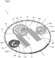
Figure 5 is a perspective view of the timepiece device offigure 1 . -
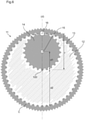
Figure 6 illustrates, in a view from above, a driving member isolated from the device offigure 5 . -
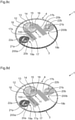
Figures 7a to 7f illustrate, in a view from above, the driving member offigure 6 in positions corresponding to different latitude settings, respectively corresponding to a latitude of 90°North (figure 7a ), a sequence showing the possible values of latitude between 90° North and 90° South (figures 7b - 7e ), and to a latitude of 90° South (figure 7f ). -
Figures 8a to 8h are perspective views of the device offigure 5 at different dates of the year, respectively December 21st, February 21st, March 21st, April 21st, June 21st, August 21st, September 21st and November 21st, for a latitude setting of 90°N. -
Figures 9a to 9d are perspective views of the device offigure 5 at different dates of the year, respectively December 21st, March 21st, June 21st, and September 21st, for a latitude setting of 45°North. - As previously mentioned,
figures 1 to 4 illustrate the display of a timepiece comprising atimepiece device 1 according to a particular embodiment of the invention. - The timepiece of
figure 1 comprises, among other things, adial 30 comprisingseveral indications hands timepiece device 1. - With reference to these
figures 1 to 4 , the day/night display device comprises a first 3 and a second 4 day/night display elements arranged to display the duration of the day and the duration of the night. Said first 3 and second 4 display elements are intertwined cut rings, corresponding respectively to anight cut ring 3 and to aday cut ring 4. Both the night cutring 3 and the day cutring 4 have the shape of a dextral circular helix whose length is equal to one pitch, as shown infigure 5 but they could be longer. - Alternatively, both the night cut
ring 3 and the day cutring 4 may have the shape of a sinister circular helix. - Other shapes for the day/night display devices are possible.
- Said cut
rings cut ring portion 3a and a visible daycut ring portion 4a. The lengths of saidvisible portions - Advantageously, the
night cut ring 3 is dark in color, typically blue and the day cutring 4 is light in color, typically yellow. Alternatively, said cutrings - Preferably, the
cut rings duration indications cut rings - The timepiece whose display is shown in
figures 1 to 4 comprises a traditional hour scale comprisinghour indexes 5 from one to twelve for the indication of the hour via atraditional hour hand 6. Atraditional minute hand 9 makes it possible to read the minutes on graduations of theminutes 10 on thedial 30. - Said timepiece also comprises an additional twenty-four hour scale comprising
additional hour indexes 7. This scale make it possible to read the hours of sunrise and sunset times. Indeed, as shown infigures 1 to 4 , at the junctions of the twocut rings - Advantageously, the time can also be read on this twenty-four hour scale by means of an additional twenty-four
hour hand 8. - We can consider that said additional twenty-four
hour hand 8 represents the sun. If the twenty-four hour-hand 8 is in within thedark section 3b, it is nighttime, and if it is within thelight section 4b, it is daytime. When the twenty-four-hour-hand 8 is at the junctions of the twocut rings - In
figures 1 to 4 , thetimepiece device 1 is set for a latitude of 48°, as shown by thelatitude indication 2 which is visible through an aperture in thedial 30. The display of the timepiece offigure 1 indicates in twoother dial 30 apertures both the date and the month. - The display of the timepiece of
figure 1 indicates that, at a latitude of 48°, on March 21st, the length of the day is around twelve hours and the length of the night is also around twelve hours. It can also be read that the sunrise occurs at around 6 o'clock and the sunset occurs at around 18 o'clock. Indeed, the junctions of the twocut rings additional hour indexes 7 "6" and "18". The display indicates 8:33 pm. Indeed, thetraditional hour 6 andminute 9 hands indicate 8:33 and theadditional hour hand 8 indicates around 20:30, showing that it is an hour of the night. Moreover, the display shows that the night began about two and a half hours ago (theadditional hand 8 is in front of the dark part of the ring, in the middle of the hour section having the indication ofduration 3b "3"). - The display of the timepiece of
figure 2 shows that, on June 21st, sun rises at around 4:15 a.m and sunset is at around 8:15 p.m. The dial is represented at 6:52 p.m. The length of the day is around 16 hours and the length of the night is around 8 hours; theadditional hour hand 8 indicates around 18:50 (figure 2 ). - The display of the timepiece of
figure 3 shows that, on September 21st, sun rises at around 6 a.m and sunset is at around 6 p.m. Thedial 30 is represented at 6:55 p.m. The length of the day is around 12 hours and the length of the night is around 12 hours (figure 3 ). - The display of the timepiece of
figure 4 shows that, on December 21st, sun rises at around 8 a.m and sunset is at around 4:20 p.m. The dial is represented at 6:54 p.m. The length of day is around 8 hours and 20 minutes and the length of night is around 15 hours and 40 minutes (figure 4 ). - As shown in
figure 5 , thetimepiece device 1 comprises adriving member 11, atransmission element 17, twomultiplier gear trains - The driving
member 11 is intended to be rotated about anaxis 100 at a speed of one revolution per year. It comprises alatitude pin 16 at a distance r from saidaxis 100 and a latitude setting device for setting the value of the distance r. Indeed, to each value or r corresponds a latitude value. - When the latitude setting is done, the value of r is fixed and the
latitude pin 16 thus describes a circle C whose radius r depends on the preselected latitude, revolving one revolution per year. - The
latitude pin 16 cooperates with aslot 18 of thetransmission element 17 in which it is inserted, it is slidable inside saidslot 18. Theslot 18 extends along a straight line. Thanks to this cooperation, thelatitude pin 16 drives thetransmission element 17 in alternating movements whose amplitude depends on the value of r and therefore on the latitude. The drivingmember 11 and thelatitude pin 16 constitute a crank for driving thetransmission element 17. - The
transmission element 17 comprises a first 17a and a second 17b portions kinematically connected respectively to the first 3 and to the second 4 elements of the day/night display device, respectively via a firstmultiplier gear train 19a and a via a secondmultiplier gear train 19b, so that the day/night display device displays the duration of the day and the duration of the night. - In the
timepiece device 1, the first 17a and second 17b portions of thetransmission element 17 respectively comprise a first and a second racks. - The first rack of the transmission element meshes with a
first gear wheel 20a of the firstmultiplier gear train 19a, said firstmultiplier gear train 19a causing thefirst element 3 of the day/night display device to move. The firstmultiplier gear train 19a comprises thefirst gear wheel 20a, apinion 21a that meshes with saidfirst gear wheel 20a and rotates around anaxis 200a, and asecond gear wheel 22a which is coaxial and fixed in rotation with thepinion 21a, saidsecond gear wheel 22a meshing with an internal toothing of thefirst element 3 of the day/night display device. - Similarly, the second rack of the
transmission element 17 meshes with afirst gear wheel 20b of a secondmultiplier gear train 19b, said secondmultiplier gear train 19b causing thesecond element 4 of the day/night display device to move. The secondmultiplier gear train 19b comprises thefirst gear wheel 20b, apinion 21b that meshes with saidfirst gear wheel 20b and rotates around anaxis 200b, and asecond gear wheel 22b which is coaxial and fixed in rotation with thepinion 21b, saidsecond gear wheel 22b meshing with an internal toothing of thesecond element 4 of the day/night display device. - Said first 17a and second 17b portions of the
transmission element 17 are guided in translation in a direction T perpendicular to that in which theslot 18 extends, by the first and secondmultiplier gear trains figure 5 . In the particular embodiment described above, thanks to theslot 18 that extends along a straight line in which thelatitude pin 16 is slidable, theentire transmission element 17 can move according to a translation movement. - As mentioned before, the driving
member 11 comprises alatitude pin 16 at a distance r from theaxis 100 and a latitude setting device for setting the value of the distance r. -
Figure 6 shows the drivingmember 11 isolated. As shown in thisfigure 6 , the latitude setting device comprises: a gearedwheel 12 pivoting about theaxis 100, aring 13 having both internal and external toothing and being coaxial to thewheel 12, astud 15 and apinion 14. - The
stud 15 is parallel to theaxis 100 and fixedly mounted on thewheel 12. It is eccentric of its axis ofrotation 100 by a distance d1. Said distance d1 corresponds to half of the distance d2 separating saidaxis 100 from the internal toothing of thering 13. - The
pinion 14 has a radius corresponding to d1 and is free to rotate around thestud 15. It carries, on its outer perimeter, thelatitude pin 16 and meshes with the internal toothing of thering 13. - The position of the
stud 15 on thewheel 12 and the dimensions of thepinion 14 are designed so that the toothing of thepinion 14 meshes continuously with the internal toothing of thering 13. - The
pinion 14 carries thelatitude pin 16 on its circumference, as shown for example infigure 6 . - The
ring 13 is frictionally mounted on thewheel 12 so that they rotate together except when setting the latitude. - For the setting of the latitude, the
ring 13 and thewheel 12 have to be moved in rotation one relative to each other. The relative displacement of thewheel 12 with respect to thering 13 causes the rotation of thepinion 14 along the internal toothing of thering 13 and results in the variation of the previously defined distance r, r being comprised between 0 and d2. - The ratio of dimensions between the diameter of the
pinion 14 and the diameter of the inner toothing of thering 13 causes, when thewheel 12 is pivoted with respect to thering 13, thelatitude pin 16 to move along a straight line (d) passing by theaxis 100. The position of thelatitude pin 16 along said line (d) sets the latitude. - In the
timepiece device 1, the external toothing of thering 13 is intended to be kinematically connected to the going train of a clockwork movement in order to be continuously rotated around its axis ofrotation 100 at a speed of one revolution per year. As indicated before, most of the time, thering 13 also rotates thewheel 12 at a speed of one revolution per year. But, during the setting of the latitude, thewheel 12 is able to be rotated relative to thering 13 by means of a control organ comprising a latitude crown (not represented) and kinematically connected to its toothing, said control organ being set to be actualized by the user. - Alternatively, the setting of the latitude may be done by any convenient control organ.
-
Figures 7a to 7f illustrate the behavior of the drivingmember 11 during the setting of the latitude. As mentioned before, during the setting of the latitude, thewheel 12 rotates relatively to thering 13. - As the
ring 13 rotates at a speed of one revolution per year, it can be considered as motionless during the setting of the latitude. - The "starting position" illustrated in
figure 7a , where thelatitude pin 16 is on the circle defined by the circumference of the inner toothing of thering 13, corresponds to a setting of a latitude of 90° North. By definition, it also corresponds to an angle of rotation of thewheel 12 relative to thering 13 of 0°. - When the
wheel 12 is rotated of 90° clockwise relatively to thering 13, starting from the previously defined "starting position", the position of thelatitude pin 16 coincides with the center of thewheel 12 that is crossed by theaxis 100, it corresponds to a setting of a latitude of 0° (figure 7d ). - When the
wheel 12 is rotated of 180° clockwise relatively to thering 13, starting from the previously defined "starting position", thelatitude pin 16 is on the circle defined by the circumference of the inner toothing of thering 13 and corresponds to a setting of a latitude of 90°South (figure 7f ). - Table 1 hereunder shows the correspondences between the angles of rotation of the
wheel 12 relative to thering 13 and the latitude set values.Table 1: Angle of rotation of the ring 13 relative to thewheel 120° 90° 180° Latitude 90° N 0° 90° S Corresponding figure 7a 7d 7f - When the latitude setting is completed, the distance r is fixed. Then, the
wheel 12 rotates again in solidarity with thering 13, and thelatitude pin 16 of the drivingmember 11 thus rotates at a speed of one revolution per year, describing a circle C whose radius r depends on the preselected latitude (figures 8a to 8h ). - As explained before, said
latitude pin 16 then drives thetransmission element 17 in alternating translational movements whose amplitude is all the greater as the latitude is extreme (close to the poles). These alternating movements are, through the multiplier gear trains, transmitted to the day/night display device in order to display the durations of the day and the night. - There are two extreme cases.
- In the first extreme case, the
latitude pin 16 is located in the center of the wheel 12 (figure 7d ) and thetransmission element 17 never moves (equator). In that case, the cut rings 3, 4 always indicate twelve hours of day and twelve hours of night. - In the second extreme case, the
latitude pin 16 coincide with the internal toothing of thetoothed ring 13. In that case, thetransmission element 17 moves in translation from a first extreme high position in which only the night part of the rings is visible (constant night; see.figure 8a ) towards a second extreme low position in which only the day part of the rings is visible (constant day, see.figure 8e ). - As mentioned before,
figures 8a to 8h are perspective views of thewatchmaking device 1 at different dates of the year, for a latitude setting of 90°N. -
Figure 8a shows that, on the 21st of December, at a latitude of 90°N, only thedark cut ring 3 of the device is visible, it is constant night. December, 21st marks the beginning of the winter. The south pole of the earth directs towards the sun, the North Pole directs away from the sun. Every position on earth on a latitude between 66° north (arctic circle) and 90° north (north pole) in the northern hemisphere has twenty-four hours nighttime (winter). Every position on earth on a latitude between 66° south (antarctic circle) and 90° south (south pole) in the southern hemisphere has twenty-four hours daylight (summer). Every position on earth on a latitude between 23.5° north (tropic of cancer) and 23.5° south has twelve hours daylight and twelve hours nighttime. -
Figure 8b shows that, on the 21st of February, at a latitude of 90°N, thedark cut ring 3 is more visible than thelight cut ring 4 which means that the night is much longer than the day (around three hours daytime and twenty-one hours nighttime). -
Figure 8c shows that, on the 21st of March, at a latitude of 90°N, thevisible part 3a of thedark cut ring 3 is as big as thevisible part 4a of thelight cut ring 4 which means that there are as many hours of day as there are hours of night (twelve hours of night and twelve hours of day). March 21st marks the spring or vernal equinox in the northern hemisphere and the autumnal or fall equinox in the southern hemisphere, this day marks the beginning of spring. Anywhere on the planet, this day has twelve hours daylight and twelve hours nighttime. It means that day and night are equally long. -
Figure 8d shows that, on the 21st of April, at a latitude of 90°N, thelight cut ring 4 is more visible than thedark cut ring 3 which means that the day is much longer than the night (around twenty hours daytime and four hours nighttime). -
Figure 8e shows that, on the 21st of June, at a latitude of 90°N, only thelight cut ring 4 of the day/night display device is visible, it is constant day. June 21st marks the summer solstice in the northern hemisphere and the winter solstice in the southern hemisphere, which is the day of the year with the most hours of daylight in the northern hemisphere and the fewest hours of daylight in the southern hemisphere. This day marks the beginning of summer. The north pole of the earth directs towards sun, the south pole directs away from the sun. Every position on earth on a latitude between 66° north (arctic circle) and 90° north (north pole) in the northern hemisphere has 24 hours daylight (summer). Every position on earth on a latitude between 66° south (antarctic circle) and 90° south (south pole) in the southern hemisphere has 24 hours nighttime (winter). Every position on earth on a latitude between 23.5° north (tropic of cancer) and 23.5° south (tropic of capricorn) has twelve hours daylight and twelve hours nighttime. -
Figure 8f shows that, on the 21st of August, at a latitude of 90°N, thelight cut ring 4 is more visible than thedark cut ring 3 which means that the day is much longer than the night (around twenty hours daytime and four hours nighttime). -
Figure 8g shows that, on the 21st of September, at a latitude of 90°N, the visible part of thedark cut ring 3 is as big as the visible part of thelight cut ring 4 which means that there are as many hours of day as there are hours of night (twelve hours of night and twelve hours of day). September 21st marks the autumnal or fall equinox in the northern hemisphere and the spring or vernal equinox in the southern hemisphere. This day marks the beginning of autumn. This day has twelve hours daylight and twelve hours nighttime: day and night are equally long. -
Figure 8h shows that, on the 21st of November, thedark cut ring 3 is more visible than thelight cut ring 4 which means that the night is much longer than the day (around three hours daytime and twenty-one hours nighttime). -
Figures 9a to 9d are perspective views of thesame timepiece device 1 at different dates of the year, for a latitude setting of 45°N. -
Figure 9a shows that, on the 21st of December, at a latitude of 45°N, thedark cut ring 3 is more visible than thelight cut ring 4 which means that the night is much longer than the day (around eight hours daytime and sixteen hours nighttime). -
Figure 9b shows that, on the 21st of March, at a latitude of 45°N, thevisible part 3a of thedark cut ring 3 is as big as thevisible part 4a of thelight cut ring 4 which means that there are as many hours of day as there are hours of night (twelve hours of night and twelve hours of day), day and night are equally long. -
Figure 9c shows that, on the 21st of June, at a latitude of 45°N, thelight cut ring 4 is more visible than thedark cut ring 3 which means that the day is much longer than the night (around sixteen hours daytime and eight hours nighttime). -
Figure 9d shows that, on the 21st of September, at a latitude of 45°N, the visible part a of thedark cut ring 3 is as big as thevisible part 4a of thelight cut ring 4 which means that there are as many hours of day as there are hours of night (twelve hours of night and twelve hours of day), day and night are equally long. - As mentioned before, the invention also concerns a timepiece including a device according to the invention, whose display is, for example, as represented in
figures 1 to 4 . Such a timepiece typically includes a clockwork movement, a winding mechanism, time setting organs and indicator organs (such as a dial or hands). - Preferably, the control organ of the timepiece device according to the invention can be set from outside of the timepiece for the setting of the latitude.
- It will be apparent to those skilled in the art that the present invention is not limited to the embodiment shown in the figures. For example, it is not limited to a particular shape for the
transmission element 17, to a specific shape for the drivingmember 11 or to a specific day/night display device. - The racks of the first 17a and second 17b portions of the
transmission element 17 that kinematically connect thetransmission element 17 respectively to the first 3 and second 4 elements of the day/night display device could be replaced, for example, by toothed structures other than racks, by toothless structures cooperating with other toothless structures like toothless wheels by adhesion or friction or by any other drive structures able to kinematically connect theseportions transmission element 17 to theelements - In the particular embodiment described above, the
transmission element 17 comprises aslot 18 in which thelatitude pin 16 is slidable, so that theentire transmission element 17 can move according to a translation movement. Alternatively, theslot 18 could be replaced by any convenient means of cooperation, for example by a simple hole in which thelatitude pin 16 would pivot. In this case only a part of thetransmission element 17 comprising the first 17a and second 17b portions would be guided in translation. - In the particular embodiment described above, the external toothing of the
ring 13 is intended to be kinematically connected to the going train of a clockwork movement in order to be continuously rotated around its axis ofrotation 100 at a speed of one revolution per year and thewheel 12 is intended to be actuated by a user for the setting of the latitude by means of a control organ kinematically connected to the toothing of thewheel 12. Alternatively, it is possible to train the drivingmember 11 in rotation at a speed of one revolution per year by acting on thewheel 12 and to set the latitude by acting on thering 13. - The timepiece device according to the invention can easily be modified in order to also indicate summer time and winter time. Indeed, in many countries around the world the hour hand has to be moved one hour or a half hour forward or backward at the beginning of spring or autumn (for some locations are also only half hours).
Claims (13)
- Timepiece device (1) comprising a driving member (11), a transmission element (17) and a display device (3, 4), said driving member (11) being intended to pivot about an axis (100) at a speed of one revolution per year and comprising a latitude pin (16) at a distance r from said axis (100) and a latitude setting device for setting the value of the distance r, each value of r corresponding to a defined value of latitude and remains fixed once its setting has been made, said latitude pin (16) cooperating with a means of cooperation (18) of the transmission element (17) for driving the latter in alternating movements, at least a part of the transmission element (17) being guided in translation, the part of the transmission element being guided in translation comprising at least a first (17a) and a second (17b) portions kinematically connected respectively to a first (3) and a second (4) elements of the display device, said first (3) and second (4) elements being arranged to display the duration of the day and the duration of the night, said timepiece device (1) comprising a control organ, said control organ typically comprising a latitude crown, for setting the latitude and characterized in that said latitude setting device comprises : a wheel (12) having an external gear and pivoting about said axis (100); a ring (13), having both internal and external toothing and being coaxial to the wheel (12); a stud (15), parallel to said axis (100), fixedly mounted on the wheel (12) and eccentric by a distance d1 from said axis (100), the distance d1 corresponding to half of the distance d2 separating said axis (100) from the internal toothing of the ring (13); and a pinion (14) of radius d1, free to rotate about the stud (15), said pinion (14) carrying, on its outer perimeter, the latitude pin (16) and meshing with the internal toothing of the ring (13); all arranged so that, when setting the latitude, it is possible to rotate the wheel (12) relative to the ring (13) in order to set the distance r, r being between 0 and d2.
- Timepiece device (1) according to claim 1, characterized in that said ring (13) is frictionally mounted on the wheel (12) so that they rotate together except when setting the latitude.
- Timepiece device (1) according to any of claims 1 and 2, characterized in that the ring (13) is intended to be continuously driven in rotation at a speed of one revolution per year and in that during the setting of the latitude, the wheel (12) is rotated relative to the ring (13) by actuating said control organ.
- Timepiece device (1) according to any of claims 1 and 2, characterized in that the wheel (12) is intended to be continuously driven in rotation at a speed of one revolution per year and in that, during the setting of the latitude, the ring (13) is rotated relative to the wheel (12) by actuating said control organ.
- Timepiece device (1) according to one of the preceding claims, characterized in that both said first (3) and second (4) elements are in the form of a circular helix, both dextral or both sinister, each of said first (3) and second (4) elements being of a length at least equal to one pitch, said elements (3, 4) being arranged in such a way that the angular position of one element with respect to the other one leads to the definition of visible portions (3a, 4a) of these elements (3, 4), the length of the visible portions (3a, 4a) of said first (3) and second (4) elements respectively being indicative of the duration of the day and of the duration of the night.
- Timepiece device (1) according to one of the preceding claims, characterized in that said first (17a) and second (17b) portions of the transmission element (17) respectively comprise a first and a second toothing intended to mesh respectively with a first (19a) and a second (19b) multiplier gear trains, these multiplier gear trains (19a, 19b) meshing respectively with a toothing of said first element (3) and with a toothing of said second element (3).
- Timepiece device (1) according to one of the preceding claims, characterized in that said means of cooperation comprise a slot (18), the latitude pin (16) being inserted into said slot (18) and being slidable inside.
- Timepiece device (1) according to claim 7, characterized in that said slot (18) extends in a direction perpendicular to the direction T of the translation movements of the transmission element (17).
- Timepiece device (1) according to one of claims 6 to 8, characterized in that the transmission element (17) is guided in translation by said multiplier gear trains (19a; 19b).
- Timepiece device (1) according to one of the preceding claims, characterized in that, during the setting of the latitude, the latitude pin (16) moves along a straight line (d), said straight line (d) passing by the axis of rotation (100) of the driving member (11).
- Timepiece such as a pocket watch or a wristwatch comprising a clockwork movement and a timepiece device (1) according to one of claims 1 to 10.
- Timepiece according to claim 11, characterized in that said latitude setting device is operable from outside the timepiece.
- Timepiece according to claim 11 or 12, characterized in that said timepiece comprises a twenty-four hour graduation (7) on or around the dial (30) making it possible to read the hours of sunrise and sunset.
Priority Applications (1)
| Application Number | Priority Date | Filing Date | Title |
|---|---|---|---|
| EP18159967.1A EP3537227B1 (en) | 2018-03-05 | 2018-03-05 | Timepiece device for the display of the duration of day and night |
Applications Claiming Priority (1)
| Application Number | Priority Date | Filing Date | Title |
|---|---|---|---|
| EP18159967.1A EP3537227B1 (en) | 2018-03-05 | 2018-03-05 | Timepiece device for the display of the duration of day and night |
Publications (2)
| Publication Number | Publication Date |
|---|---|
| EP3537227A1 EP3537227A1 (en) | 2019-09-11 |
| EP3537227B1 true EP3537227B1 (en) | 2022-03-02 |
Family
ID=61563302
Family Applications (1)
| Application Number | Title | Priority Date | Filing Date |
|---|---|---|---|
| EP18159967.1A Active EP3537227B1 (en) | 2018-03-05 | 2018-03-05 | Timepiece device for the display of the duration of day and night |
Country Status (1)
| Country | Link |
|---|---|
| EP (1) | EP3537227B1 (en) |
Family Cites Families (4)
| Publication number | Priority date | Publication date | Assignee | Title |
|---|---|---|---|---|
| CH690516A5 (en) | 1998-11-27 | 2000-09-29 | Patek Philippe Sa | Wrist watch with sunrise and sunset times includes two shutters moving over arced window to define range of times for sunlit hours during day |
| EP1989597B1 (en) * | 2006-03-01 | 2019-06-26 | Vincent Plomb | Watch with at least one three-dimensional indicator comlementary to time information |
| WO2016029296A1 (en) * | 2014-08-29 | 2016-03-03 | Mouret Nicolas | Mechanism for displaying sunrise and/or sunset times at different latitudes, kit with components for assembling such a mechanism, and corresponding methods of assembly, operation and use |
| CH712374A1 (en) * | 2016-04-19 | 2017-10-31 | Mft Et Fabrique De Montres Et Chronomètres Ulysse Nardin Le Locle S A | Device for displaying the times of sunrise and sunset. |
-
2018
- 2018-03-05 EP EP18159967.1A patent/EP3537227B1/en active Active
Also Published As
| Publication number | Publication date |
|---|---|
| EP3537227A1 (en) | 2019-09-11 |
Similar Documents
| Publication | Publication Date | Title |
|---|---|---|
| US4548512A (en) | Watch with indicator of lunar phases | |
| US5508979A (en) | Timepiece with indication of the part of the earth visible from the moon | |
| US5023849A (en) | Astronomic timepiece and disc intended for use therein | |
| US4711583A (en) | Astronomical wrist-watch | |
| US11036185B2 (en) | Timepiece mechanism for displaying the lunar day and moon phase, with a correction system using a double kinematic chain | |
| EP0220048B1 (en) | Timepiece having a star display | |
| US7372781B2 (en) | Watch comprising a solar time display | |
| US3503203A (en) | Two-zone timepiece | |
| US6842404B2 (en) | Display device for watches | |
| JP2009528526A (en) | Wristwatch with at least one three-dimensional time indicator | |
| JPH10506472A (en) | Clock with two displays for displaying two different local times | |
| US6507536B1 (en) | Moon-phase dial mechanism | |
| US8787118B2 (en) | Universal watch | |
| EP3537227B1 (en) | Timepiece device for the display of the duration of day and night | |
| RU2426165C1 (en) | Clock with lunar phase indication on dial (versions) and method of indicating lunar phase on clock dial | |
| US4090352A (en) | Reducing gear-train of an electronic watch with analog display | |
| RU146127U1 (en) | CLOCK WITH MECHANICAL DEVICE FOR DISPLAYING THE MOVEMENT OF THE MOON AROUND THE EARTH REGARDING THE SUN | |
| JPH0354496A (en) | Astronomical clock with visual element simulating movement of stars | |
| JP5135014B2 (en) | Clock with moon position and age display mechanism | |
| RU2564452C1 (en) | Watch with lunar phases indicator and lunar calendar and method of implementation of said indication | |
| RU2427867C1 (en) | Device and method of indicating moon phases on jewish calendar | |
| EP0869411A2 (en) | Moon phase dial mechanism | |
| RU2557345C1 (en) | Clock with mechanical device for displaying moon movement around earth relative to sun | |
| US5327400A (en) | Time piece with lunar phase and tides display | |
| RU134335U1 (en) | CLOCK INDICATED DAYS |
Legal Events
| Date | Code | Title | Description |
|---|---|---|---|
| PUAI | Public reference made under article 153(3) epc to a published international application that has entered the european phase |
Free format text: ORIGINAL CODE: 0009012 |
|
| STAA | Information on the status of an ep patent application or granted ep patent |
Free format text: STATUS: THE APPLICATION HAS BEEN PUBLISHED |
|
| AK | Designated contracting states |
Kind code of ref document: A1 Designated state(s): AL AT BE BG CH CY CZ DE DK EE ES FI FR GB GR HR HU IE IS IT LI LT LU LV MC MK MT NL NO PL PT RO RS SE SI SK SM TR |
|
| AX | Request for extension of the european patent |
Extension state: BA ME |
|
| STAA | Information on the status of an ep patent application or granted ep patent |
Free format text: STATUS: REQUEST FOR EXAMINATION WAS MADE |
|
| 17P | Request for examination filed |
Effective date: 20200214 |
|
| RBV | Designated contracting states (corrected) |
Designated state(s): AL AT BE BG CH CY CZ DE DK EE ES FI FR GB GR HR HU IE IS IT LI LT LU LV MC MK MT NL NO PL PT RO RS SE SI SK SM TR |
|
| STAA | Information on the status of an ep patent application or granted ep patent |
Free format text: STATUS: EXAMINATION IS IN PROGRESS |
|
| 17Q | First examination report despatched |
Effective date: 20200701 |
|
| STAA | Information on the status of an ep patent application or granted ep patent |
Free format text: STATUS: EXAMINATION IS IN PROGRESS |
|
| GRAP | Despatch of communication of intention to grant a patent |
Free format text: ORIGINAL CODE: EPIDOSNIGR1 |
|
| STAA | Information on the status of an ep patent application or granted ep patent |
Free format text: STATUS: GRANT OF PATENT IS INTENDED |
|
| INTG | Intention to grant announced |
Effective date: 20211004 |
|
| GRAS | Grant fee paid |
Free format text: ORIGINAL CODE: EPIDOSNIGR3 |
|
| GRAA | (expected) grant |
Free format text: ORIGINAL CODE: 0009210 |
|
| STAA | Information on the status of an ep patent application or granted ep patent |
Free format text: STATUS: THE PATENT HAS BEEN GRANTED |
|
| AK | Designated contracting states |
Kind code of ref document: B1 Designated state(s): AL AT BE BG CH CY CZ DE DK EE ES FI FR GB GR HR HU IE IS IT LI LT LU LV MC MK MT NL NO PL PT RO RS SE SI SK SM TR |
|
| REG | Reference to a national code |
Ref country code: GB Ref legal event code: FG4D |
|
| REG | Reference to a national code |
Ref country code: CH Ref legal event code: EP Ref country code: AT Ref legal event code: REF Ref document number: 1472762 Country of ref document: AT Kind code of ref document: T Effective date: 20220315 |
|
| REG | Reference to a national code |
Ref country code: DE Ref legal event code: R096 Ref document number: 602018031467 Country of ref document: DE |
|
| REG | Reference to a national code |
Ref country code: IE Ref legal event code: FG4D |
|
| REG | Reference to a national code |
Ref country code: LT Ref legal event code: MG9D |
|
| REG | Reference to a national code |
Ref country code: NL Ref legal event code: MP Effective date: 20220302 |
|
| PG25 | Lapsed in a contracting state [announced via postgrant information from national office to epo] |
Ref country code: SE Free format text: LAPSE BECAUSE OF FAILURE TO SUBMIT A TRANSLATION OF THE DESCRIPTION OR TO PAY THE FEE WITHIN THE PRESCRIBED TIME-LIMIT Effective date: 20220302 Ref country code: RS Free format text: LAPSE BECAUSE OF FAILURE TO SUBMIT A TRANSLATION OF THE DESCRIPTION OR TO PAY THE FEE WITHIN THE PRESCRIBED TIME-LIMIT Effective date: 20220302 Ref country code: NO Free format text: LAPSE BECAUSE OF FAILURE TO SUBMIT A TRANSLATION OF THE DESCRIPTION OR TO PAY THE FEE WITHIN THE PRESCRIBED TIME-LIMIT Effective date: 20220602 Ref country code: LT Free format text: LAPSE BECAUSE OF FAILURE TO SUBMIT A TRANSLATION OF THE DESCRIPTION OR TO PAY THE FEE WITHIN THE PRESCRIBED TIME-LIMIT Effective date: 20220302 Ref country code: HR Free format text: LAPSE BECAUSE OF FAILURE TO SUBMIT A TRANSLATION OF THE DESCRIPTION OR TO PAY THE FEE WITHIN THE PRESCRIBED TIME-LIMIT Effective date: 20220302 Ref country code: ES Free format text: LAPSE BECAUSE OF FAILURE TO SUBMIT A TRANSLATION OF THE DESCRIPTION OR TO PAY THE FEE WITHIN THE PRESCRIBED TIME-LIMIT Effective date: 20220302 Ref country code: BG Free format text: LAPSE BECAUSE OF FAILURE TO SUBMIT A TRANSLATION OF THE DESCRIPTION OR TO PAY THE FEE WITHIN THE PRESCRIBED TIME-LIMIT Effective date: 20220602 |
|
| REG | Reference to a national code |
Ref country code: AT Ref legal event code: MK05 Ref document number: 1472762 Country of ref document: AT Kind code of ref document: T Effective date: 20220302 |
|
| PG25 | Lapsed in a contracting state [announced via postgrant information from national office to epo] |
Ref country code: PL Free format text: LAPSE BECAUSE OF FAILURE TO SUBMIT A TRANSLATION OF THE DESCRIPTION OR TO PAY THE FEE WITHIN THE PRESCRIBED TIME-LIMIT Effective date: 20220302 Ref country code: LV Free format text: LAPSE BECAUSE OF FAILURE TO SUBMIT A TRANSLATION OF THE DESCRIPTION OR TO PAY THE FEE WITHIN THE PRESCRIBED TIME-LIMIT Effective date: 20220302 Ref country code: GR Free format text: LAPSE BECAUSE OF FAILURE TO SUBMIT A TRANSLATION OF THE DESCRIPTION OR TO PAY THE FEE WITHIN THE PRESCRIBED TIME-LIMIT Effective date: 20220603 Ref country code: FI Free format text: LAPSE BECAUSE OF FAILURE TO SUBMIT A TRANSLATION OF THE DESCRIPTION OR TO PAY THE FEE WITHIN THE PRESCRIBED TIME-LIMIT Effective date: 20220302 |
|
| PG25 | Lapsed in a contracting state [announced via postgrant information from national office to epo] |
Ref country code: NL Free format text: LAPSE BECAUSE OF FAILURE TO SUBMIT A TRANSLATION OF THE DESCRIPTION OR TO PAY THE FEE WITHIN THE PRESCRIBED TIME-LIMIT Effective date: 20220302 |
|
| REG | Reference to a national code |
Ref country code: DE Ref legal event code: R119 Ref document number: 602018031467 Country of ref document: DE |
|
| PG25 | Lapsed in a contracting state [announced via postgrant information from national office to epo] |
Ref country code: SM Free format text: LAPSE BECAUSE OF FAILURE TO SUBMIT A TRANSLATION OF THE DESCRIPTION OR TO PAY THE FEE WITHIN THE PRESCRIBED TIME-LIMIT Effective date: 20220302 Ref country code: SK Free format text: LAPSE BECAUSE OF FAILURE TO SUBMIT A TRANSLATION OF THE DESCRIPTION OR TO PAY THE FEE WITHIN THE PRESCRIBED TIME-LIMIT Effective date: 20220302 Ref country code: RO Free format text: LAPSE BECAUSE OF FAILURE TO SUBMIT A TRANSLATION OF THE DESCRIPTION OR TO PAY THE FEE WITHIN THE PRESCRIBED TIME-LIMIT Effective date: 20220302 Ref country code: PT Free format text: LAPSE BECAUSE OF FAILURE TO SUBMIT A TRANSLATION OF THE DESCRIPTION OR TO PAY THE FEE WITHIN THE PRESCRIBED TIME-LIMIT Effective date: 20220704 Ref country code: EE Free format text: LAPSE BECAUSE OF FAILURE TO SUBMIT A TRANSLATION OF THE DESCRIPTION OR TO PAY THE FEE WITHIN THE PRESCRIBED TIME-LIMIT Effective date: 20220302 Ref country code: CZ Free format text: LAPSE BECAUSE OF FAILURE TO SUBMIT A TRANSLATION OF THE DESCRIPTION OR TO PAY THE FEE WITHIN THE PRESCRIBED TIME-LIMIT Effective date: 20220302 Ref country code: AT Free format text: LAPSE BECAUSE OF FAILURE TO SUBMIT A TRANSLATION OF THE DESCRIPTION OR TO PAY THE FEE WITHIN THE PRESCRIBED TIME-LIMIT Effective date: 20220302 |
|
| PG25 | Lapsed in a contracting state [announced via postgrant information from national office to epo] |
Ref country code: IS Free format text: LAPSE BECAUSE OF FAILURE TO SUBMIT A TRANSLATION OF THE DESCRIPTION OR TO PAY THE FEE WITHIN THE PRESCRIBED TIME-LIMIT Effective date: 20220702 Ref country code: AL Free format text: LAPSE BECAUSE OF FAILURE TO SUBMIT A TRANSLATION OF THE DESCRIPTION OR TO PAY THE FEE WITHIN THE PRESCRIBED TIME-LIMIT Effective date: 20220302 |
|
| REG | Reference to a national code |
Ref country code: BE Ref legal event code: MM Effective date: 20220331 |
|
| PLBE | No opposition filed within time limit |
Free format text: ORIGINAL CODE: 0009261 |
|
| STAA | Information on the status of an ep patent application or granted ep patent |
Free format text: STATUS: NO OPPOSITION FILED WITHIN TIME LIMIT |
|
| PG25 | Lapsed in a contracting state [announced via postgrant information from national office to epo] |
Ref country code: MC Free format text: LAPSE BECAUSE OF FAILURE TO SUBMIT A TRANSLATION OF THE DESCRIPTION OR TO PAY THE FEE WITHIN THE PRESCRIBED TIME-LIMIT Effective date: 20220302 Ref country code: LU Free format text: LAPSE BECAUSE OF NON-PAYMENT OF DUE FEES Effective date: 20220305 Ref country code: IE Free format text: LAPSE BECAUSE OF NON-PAYMENT OF DUE FEES Effective date: 20220305 Ref country code: FR Free format text: LAPSE BECAUSE OF NON-PAYMENT OF DUE FEES Effective date: 20220502 Ref country code: DK Free format text: LAPSE BECAUSE OF FAILURE TO SUBMIT A TRANSLATION OF THE DESCRIPTION OR TO PAY THE FEE WITHIN THE PRESCRIBED TIME-LIMIT Effective date: 20220302 Ref country code: DE Free format text: LAPSE BECAUSE OF NON-PAYMENT OF DUE FEES Effective date: 20221001 |
|
| 26N | No opposition filed |
Effective date: 20221205 |
|
| PG25 | Lapsed in a contracting state [announced via postgrant information from national office to epo] |
Ref country code: SI Free format text: LAPSE BECAUSE OF FAILURE TO SUBMIT A TRANSLATION OF THE DESCRIPTION OR TO PAY THE FEE WITHIN THE PRESCRIBED TIME-LIMIT Effective date: 20220302 Ref country code: BE Free format text: LAPSE BECAUSE OF NON-PAYMENT OF DUE FEES Effective date: 20220331 |
|
| GBPC | Gb: european patent ceased through non-payment of renewal fee |
Effective date: 20220602 |
|
| PG25 | Lapsed in a contracting state [announced via postgrant information from national office to epo] |
Ref country code: GB Free format text: LAPSE BECAUSE OF NON-PAYMENT OF DUE FEES Effective date: 20220602 |
|
| P01 | Opt-out of the competence of the unified patent court (upc) registered |
Effective date: 20230521 |
|
| PG25 | Lapsed in a contracting state [announced via postgrant information from national office to epo] |
Ref country code: IT Free format text: LAPSE BECAUSE OF FAILURE TO SUBMIT A TRANSLATION OF THE DESCRIPTION OR TO PAY THE FEE WITHIN THE PRESCRIBED TIME-LIMIT Effective date: 20220302 |
|
| PGFP | Annual fee paid to national office [announced via postgrant information from national office to epo] |
Ref country code: CH Payment date: 20230401 Year of fee payment: 6 |