EP3536999A1 - Clutch unit and vehicle - Google Patents
Clutch unit and vehicle Download PDFInfo
- Publication number
- EP3536999A1 EP3536999A1 EP17888622.2A EP17888622A EP3536999A1 EP 3536999 A1 EP3536999 A1 EP 3536999A1 EP 17888622 A EP17888622 A EP 17888622A EP 3536999 A1 EP3536999 A1 EP 3536999A1
- Authority
- EP
- European Patent Office
- Prior art keywords
- clutch
- force
- input
- spring
- output shaft
- Prior art date
- Legal status (The legal status is an assumption and is not a legal conclusion. Google has not performed a legal analysis and makes no representation as to the accuracy of the status listed.)
- Granted
Links
Images






Classifications
-
- F—MECHANICAL ENGINEERING; LIGHTING; HEATING; WEAPONS; BLASTING
- F16—ENGINEERING ELEMENTS AND UNITS; GENERAL MEASURES FOR PRODUCING AND MAINTAINING EFFECTIVE FUNCTIONING OF MACHINES OR INSTALLATIONS; THERMAL INSULATION IN GENERAL
- F16D—COUPLINGS FOR TRANSMITTING ROTATION; CLUTCHES; BRAKES
- F16D23/00—Details of mechanically-actuated clutches not specific for one distinct type
- F16D23/12—Mechanical clutch-actuating mechanisms arranged outside the clutch as such
-
- F—MECHANICAL ENGINEERING; LIGHTING; HEATING; WEAPONS; BLASTING
- F16—ENGINEERING ELEMENTS AND UNITS; GENERAL MEASURES FOR PRODUCING AND MAINTAINING EFFECTIVE FUNCTIONING OF MACHINES OR INSTALLATIONS; THERMAL INSULATION IN GENERAL
- F16D—COUPLINGS FOR TRANSMITTING ROTATION; CLUTCHES; BRAKES
- F16D13/00—Friction clutches
- F16D13/58—Details
- F16D13/75—Features relating to adjustment, e.g. slack adjusters
- F16D13/752—Features relating to adjustment, e.g. slack adjusters the adjusting device being located in the actuating mechanism arranged outside the clutch
-
- F—MECHANICAL ENGINEERING; LIGHTING; HEATING; WEAPONS; BLASTING
- F16—ENGINEERING ELEMENTS AND UNITS; GENERAL MEASURES FOR PRODUCING AND MAINTAINING EFFECTIVE FUNCTIONING OF MACHINES OR INSTALLATIONS; THERMAL INSULATION IN GENERAL
- F16D—COUPLINGS FOR TRANSMITTING ROTATION; CLUTCHES; BRAKES
- F16D28/00—Electrically-actuated clutches
Definitions
- the present teaching relates to a clutch unit capable of transferring and interrupting a torque.
- a known clutch unit includes a clutch and an actuator that generates a force for actuating the clutch (hereinafter referred to as an actuation driving force).
- Such a clutch unit is capable of switching the clutch between an engaged state and a disengaged state by using an actuation driving force generated by the actuator.
- the engaged state of the clutch refers to a state where the clutch transfer a torque
- the disengaged state of the clutch refers to a state where a torque is interrupted by the clutch.
- Such a clutch unit as described above has a known configuration including an auxiliary spring member in order to assist a switching operation of the clutch by the actuator.
- a friction clutch disclosed in Patent Document 1 includes a clutch engagement device, an electric motor, an elastic auxiliary means (coil spring), and a linkage.
- the clutch engagement device of the friction clutch disclosed in Patent Document 1 includes a friction disc, a friction lining, a flywheel, a thrust plate, and a diaphragm.
- the friction lining is disposed between the flywheel and the thrust plate, and is supported on an outer peripheral portion of the friction disc.
- a force is exerted on the thrust plate from the diaphragm.
- the friction lining is located between the flywheel and the thrust plate.
- the friction clutch disclosed in Patent Document 1 is in the engaged state in normal operation.
- the clutch unit that is in the engaged state while no force is exerted on the clutch from the actuator will be referred to as a normally closed clutch unit.
- the diaphragm is connected to an electric motor through the linkage.
- an actuation driving force generated by the electric motor is transferred to the diaphragm through the linkage.
- a center portion of the diaphragm is depressed by the linkage.
- an outer peripheral portion of the diaphragm moves away from the thrust plate. Accordingly, a force exerted on the thrust plate from the diaphragm decreases.
- a pressing force of the thrust plate against the friction lining decreases. Consequently, the friction clutch is in a disconnected state.
- the linkage is also subjected to a force generated by the elastic auxiliary means (hereinafter referred to as an assist force) in addition to the actuation driving force generated by the electric motor.
- an assist force a force generated by the elastic auxiliary means
- forces generated by the diaphragm, the electric motor, and the elastic auxiliary means in the friction clutch of Patent Document 1 will be briefly described with reference to the drawings.
- FIG. 15 is a graph for describing forces generated by the diaphragm, the electric motor, and the elastic auxiliary means in the friction clutch described in Patent Document 1.
- the ordinate represents a force exerted on the linkage
- the abscissa represents a travel distance of the linkage (travel distance of a contact portion between the linkage and the diaphragm).
- a curve C1 represents a force exerted on the linkage from the diaphragm (reaction force exerted on the linkage from the diaphragm)
- a curve C2 represents an assist force exerted on the linkage from the elastic auxiliary means
- a curve C3 represents an actuation driving force exerted on the linkage from the electric motor.
- a force exerted in a direction in which the friction clutch is switched to an engaged state is represented as a positive value
- a force exerted in a direction in which the friction clutch is switched to a disengaged state is represented as a negative value.
- the travel distance is 0 (zero) when the friction clutch is switched to the engaged state, and increases as the linkage moves in the direction in which the friction clutch is switched to the disengaged state.
- the assist force generated by the elastic auxiliary means is input to the linkage (C2 in FIG. 15 ) so as to counter a reaction force exerted on the linkage from the diaphragm (C1 in FIG. 15 ). That is, in switching the friction clutch to the engaged state or the disengaged state by the electric motor, the assist force generated by the elastic auxiliary means is exerted on the linkage as a force of assisting the electric motor. Accordingly, in the friction clutch disclosed in Patent Document 1, the friction clutch can be switched to the engaged state or the disengaged state with a small actuation driving force.
- a member that transfers a torque by a friction force (hereinafter referred to as a torque transfer member) is abraded with an operating time.
- a torque transfer member a member that transfers a torque by a friction force
- the friction lining serving as a torque transfer member is abraded with an operating time.
- the clutch engagement device is provided with a device for taking up abrasion (abrasion compensation device).
- the abrasion compensation device is configured to constantly maintain the diaphragm at the same position while the friction clutch is in the engaged state. This configuration can suppress a change in magnitude of the reaction force exerted on the linkage from the diaphragm.
- Patent Document 1 Japanese Unexamined Patent Application Publication (Translation of PCT Application) No. 2000-501826
- the clutch unit can be reduced in cost and size.
- an object of the present teaching is to obtain a clutch unit capable of coping with abrasion of a torque transfer member with a configuration different from an abrasion compensation device proposed to date.
- the inventors of the present teaching have conducted various studies on abrasion of a torque transfer member in a normally closed clutch unit. Specifically, study on abrasion of the torque transfer member was conducted for a clutch unit including a clutch including a torque transfer member, an actuator that generates an actuation driving force for actuating the clutch, an auxiliary spring member that generates an assist force for assisting the actuator, and a transfer member for transferring the actuation driving force and the assist force to the clutch. In this study, investigation was conducted on a configuration capable of coping with abrasion of the torque transfer member without compensating for abrasion of the torque transfer member.
- the inventors of the present teaching first closely investigated a phenomenon occurring in the clutch, the actuator, and the transfer member in switching the clutch to an engaged state or a disengaged state in a normally closed clutch unit.
- the timing when the clutch reaction force input to the transfer member from the clutch reaches zero becomes later by abrasion of the torque transfer member. More specifically, it was found that in switching the clutch from the disengaged state to the engaged state, abrasion of the torque transfer member causes the assist force input from the auxiliary spring member to the transfer member to be zero before the clutch reaction force input to the transfer member from the clutch becomes zero. Thus, before the clutch reaction force input to the transfer member from the clutch becomes zero, a period in which the assist force cannot be used occurs.
- the clutch is temporarily in a half-clutch state.
- the clutch needs to be controlled precisely in the period in which the clutch is in the half-clutch state.
- a period in which the assist force of the auxiliary spring member cannot be used occurs before the completion of engaging operation of the clutch.
- the clutch changes to the half-clutch state in this period, it is necessary to adjust the actuation driving force precisely while generating a large actuation driving force by the actuator. This is not favorable because of difficulty in control the actuator as well as necessity for providing a large-sized actuator in this case.
- the inventors of the present teaching have studied a configuration of a clutch unit that can prevent occurrence of a period in which the assist force cannot be used after start of disengaging operation of the clutch and before completion of engaging operation of the clutch even when the torque transfer member is abraded. As a result, the inventors finally found that the clutch unit only needs to be configured as follows.
- the clutch unit is configured to allow the assist force to be input from the auxiliary spring member to the transfer member before the clutch reaction force is input to the transfer member from the clutch in switching the clutch from the engaged state to the disengaged state.
- the clutch unit in switching the clutch to the disengaged state, even if the timing when input of the clutch reaction force to the transfer member from the clutch starts becomes earlier, it is possible to suppress input of the clutch reaction force to the transfer member from the clutch before the assist force is input to the transfer member. That is, it is possible to suppress occurrence of a period in which the assist force cannot be used before start of disengaging operation of the clutch even if the torque transfer member is abraded.
- the clutch unit only needs to be configured to allow the assist force input to the transfer member from the auxiliary spring member to be zero after the clutch reaction force input to the transfer member from the clutch becomes zero in switching the clutch from the disengaged state to the engaged state.
- the clutch unit even if the timing when the clutch reaction force input to the transfer member from the clutch reaches zero becomes later in switching the clutch to the engaged state, it is possible to suppress a decrease of the assist force input to the transfer member to zero before the clutch reaction force input to the transfer member from the clutch becomes zero. That is, it is possible to suppress occurrence of a period in which the assist force cannot be used before completion of engaging operation of the clutch even when the torque transfer member is abraded.
- a clutch unit includes: a clutch including a plurality of torque transfer members that transfer a torque by a friction force and a clutch spring that connects the plurality of torque transfer members to one another by an elastic restoring force, the clutch being switchable to an engaged state where a torque is transferred and a disengaged state where a torque is interrupted; an actuator that generates an actuation driving force for actuating the clutch; a transfer member that transfers the actuation driving force generated by the actuator to the clutch and receives the elastic restoring force of the clutch spring from the clutch as a clutch reaction force; and an auxiliary spring member that inputs an assist force for assisting the actuation driving force to the transfer member, wherein in switching the clutch from the engaged state to the disengaged state, the assist force is input to the transfer member from the auxiliary spring member before the clutch reaction force is input to the transfer member from the clutch, and in switching the clutch from the disengaged state to the engaged state, after the clutch reaction force input to the transfer member from the clutch becomes zero, the assist
- the transfer member in switching the clutch to the engaged state or the disengaged state, the transfer member receives not only the clutch reaction force exerted from the clutch but also the assist force generated by the auxiliary spring member. Accordingly, an actuation driving force necessary for switching the clutch to the engaged state or the disengaged state can be reduced.
- the transfer member In switching the clutch from the engaged state to the disengaged state, the transfer member receive the assist force from the auxiliary spring member before receiving the clutch reaction force from the clutch. In this case, in switching the clutch from the engaged state to the disengaged state, even if the timing of input of the clutch reaction force to the transfer member from the clutch becomes earlier, it is possible to suppress input of the clutch reaction force to the transfer member from the clutch before the assist force is input to the transfer member. That is, it is possible to prevent occurrence of a period in which the assist force cannot be used before start of disengaging operation of the clutch even if the torque transfer member is abraded.
- the assist force input to the transfer member from the auxiliary spring member becomes zero after the clutch reaction force input to the transfer member from the clutch becomes zero.
- the timing when the clutch reaction force input to the transfer member from the clutch reaches zero becomes later in switching the clutch from the disengaged state to the engaged state, it is possible to suppress a decrease of the assist force input to the transfer member to zero before the clutch reaction force input to the transfer member from the clutch becomes zero. That is, it is possible to suppress occurrence of a period in which the assist force cannot be used before completion of engaging operation of the clutch even when the torque transfer member is abraded.
- the clutch can be smoothly switched to the engaged state or the disengaged state to cope with the abrasion without compensation for the abrasion.
- the clutch unit according to the present teaching preferably includes the following configuration, in a state where an abrasion amount of the torque transfer member reaches a predetermined limit, in switching the clutch from the engaged state to the disengaged state, the assist force is input to the transfer member from the auxiliary spring member before the clutch reaction force is input to the transfer member from the clutch, and in switching the clutch from the disengaged state to the engaged state, after the clutch reaction force input to the transfer member from the clutch becomes zero, the assist force input to the transfer member from the auxiliary spring member becomes zero.
- the clutch can be smoothly switched to the engaged state or the disengaged state.
- the clutch unit according to the present teaching preferably includes the following configuration. in switching the clutch from the engaged state to the disengaged state, the assist force input to the transfer member from auxiliary spring member is at maximum after start of input of the clutch reaction force to the transfer member from the clutch.
- the clutch reaction force input to the transfer member from the clutch increases as the disengaging operation of the clutch progresses.
- the assist force is at maximum after input of the clutch reaction force to the transfer member from the clutch starts. Accordingly, even when the clutch reaction force input from the clutch to the transfer member increases with the progress of the disengaging operation of the clutch, a sufficient assist force can be input to the transfer member. As a result, the clutch can be smoothly switched from the engaged state to the disengaged state.
- the clutch unit according to the present teaching preferably includes the following configuration.
- the assist force input to the transfer member from auxiliary spring member is at maximum before input of the clutch reaction force to the transfer member from the clutch becomes zero.
- a vehicle according to one embodiment of the present teaching includes a clutch unit including any one of the configurations described above.
- the clutch unit according to one embodiment of the present teaching is capable of coping with abrasion of a torque transfer member with a configuration different form that of an abrasion compensation device proposed to date.
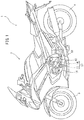
- FIG. 1 is a schematic view of a vehicle 1 including a clutch driving device 14 according to a first embodiment of the present teaching.
- the vehicle 1 is, for example, a motorcycle and includes a vehicle body 2, a front wheel 3, and a rear wheel 4.
- the vehicle body 2 includes an unillustrated frame.
- An engine unit 10 for supplying a rotation driving force to the rear wheel 4 is attached to the frame of the vehicle body 2.
- the engine unit 10 includes an engine 11, a transmission 12, and a clutch unit 17.
- the clutch unit 17 includes a clutch 13 and a clutch driving device 14.
- the clutch 13 is configured to enable transfer of rotation of an unillustrated crank shaft of the engine 11 to the transmission 12. That is, the clutch 13 is configured to be switchable between transfer and non-transfer of rotation of the crank shaft to the transmission 12.
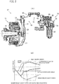
- FIGS. 2(A) and 3 are partial cross-sectional view illustrating a schematic configuration of the clutch unit 17.
- FIGS. 2(B) and 9 are views schematically illustrating a shaft torque generated in an output shaft 63 of the clutch unit 17 described later.
- FIGS. 3 and 9 are enlarged views of FIGS. 2(A) and 2(B) , respectively. Description for FIG. 9 will be given later.
- the clutch 13 is disposed on a main shaft 15.
- the main shaft 15 is, for example, an input shaft of the transmission 12.
- the clutch 13 includes a clutch housing 21 and a clutch inner 25 disposed inside the clutch housing 21.
- the clutch housing 21 has a bottomed cylindrical shape including a bottom portion 21a through which the main shaft 15 penetrates and a cylindrical peripheral wall portion 21b disposed at the outer periphery of the bottom portion 21a.
- the bottom portion 21a and the peripheral wall portion 21b are integrally formed.
- the clutch housing 21 is disposed coaxially with the main shaft 15.
- the clutch inner 25 is disposed inside the peripheral wall portion 21b of the clutch housing 21.
- the bottom portion 21a of the clutch housing 21 is connected to a speed-reducing gear 22.
- the speed-reducing gear 22 is meshed with a gear (not shown) of the crank shaft to thereby rotate together with the gear.
- the clutch housing 21 and the speed-reducing gear 22 rotate in accordance with rotation of the crank shaft, and are capable of rotating relative to the main shaft 15.
- the clutch inner 25 includes a clutch boss 26, a pressure member 27, and a clutch spring 28.
- the clutch boss 26 has a columnar shape, and the main shaft 15 penetrates the center of the columnar shape.
- the clutch boss 26 is spline-coupled to the outer peripheral surface of the main shaft 15. Accordingly, the clutch boss 26 rotates together with the main shaft 15.
- the clutch housing 21, the clutch boss 26, and the pressure member 27 are arranged in this order relative to the main shaft 15 along the axial direction of the main shaft 15 from one end thereof.
- the pressure member 27 is disposed outside the main shaft 15 in the axial direction to face the clutch boss 26 in the axial direction of the main shaft 15.
- a plurality of clutch plates 23 and a plurality of friction plates 24 are alternately arranged in the axial direction between the clutch boss 26 and the pressure member 27.
- the clutch plates 23 and the friction plates 24 correspond to torque transfer members.
- the friction plates 24 are provided to the inner peripheral surface of the clutch housing 21 to be rotatable together with the clutch housing 21.
- the friction plates 24 are rotatable with respect to the clutch boss 26 and the pressure member 27.
- the clutch plates 23 are provided to the outer peripheral surface of the clutch boss 26 to be rotatable together with the clutch boss 26.
- the pressure member 27 is rotatable together with the clutch boss 26. Accordingly, the clutch plates 23 are rotatable together with the pressure member 27.
- the clutch plates 23 are rotatable with respect to the clutch housing 21.
- the pressure member 27 is movable in the axial direction with respect to the clutch boss 26.
- the clutch spring 28 is disposed to push the pressure member 27 toward the clutch boss 26 in the axial direction. Accordingly, the clutch plates 23 and the friction plates 24 disposed between the clutch boss 26 and the pressure member 27 are pushed against with each other. That is, the clutch spring 28 connects the clutch plates 23 and the friction plates 24 to each other. In the state where the clutch plates 23 and the friction plates 24 described above, friction between the clutch plates 23 and the friction plates 24 causes the clutch boss 26 and the clutch housing 21 to rotate together. This state is an engaged state of the clutch 13.
- a push rod 29 penetrates a center portion in the axial direction of the pressure member 27.
- the push rod 29 is oriented to extend in the axial direction.
- An end in the axial direction of push rod 29 is provided with a flange portion 29a.
- the other end of the push rod 29 in the axial direction is connected to the clutch driving device 14 through a link mechanism 16 described later.
- the push rod 29 is configured to be movable in the axial direction by an output of the clutch driving device 14.
- the flange portion 29a of the push rod 29 exerts a force on the pressure member 27 in a direction away from the clutch boss 26 in the axial direction.
- the clutch spring 28 deforms to be compressed so that a force with which the pressure member 27 presses the clutch plates 23 and the friction plates 24 decreases.
- the clutch 13 is switched between the engaged state and the disengaged state by movement of the push rod 29 in the axial direction.
- the pressure member 27 is rotatable with respect to the push rod 29 with a bearing 27a interposed therebetween. Accordingly, in the engaged state of the clutch 13, the pressure member 27 rotates together with the clutch housing 21 and the clutch boss 26.
- the link mechanism 16 includes a rotating shaft 31 and an arm portion 32.
- the link mechanism 16 transfers an output of the clutch driving device 14 described later to the push rod 29 of the clutch 13.
- One end of the rotating shaft 31 in the axial direction is connected to the other end of the push rod 29 in the axial direction.
- this other end of the push rod 29 in the axial direction is provided with a rack portion 29b having a plurality of teeth arranged in the axial direction.
- the rotating shaft 31 has a gear 31a that meshes with the rack portion 29b.
- rotation of the rotating shaft 31 causes the push rod 29 to move in the axial direction. That is, the push rod 29 reciprocates in the axial direction in accordance with the rotation direction of the rotating shaft 31.
- the rotating shaft 31 is rotatably supported on a casing 20 housing the clutch 13 and the transmission 12, for example.
- the arm portion 32 includes a first arm 33, a second arm 34, and an adjustment mechanism 35.
- Each of the first arm 33 and the second arm 34 is formed in a plate shape elongated in one direction.
- the first arm 33 is connected to the rotating shaft 31 to be rotatable together with the rotating shaft 31.
- the second arm 34 is connected to the output shaft 63 of the clutch driving device 14 to be rotatable together with the output shaft 63.
- the first arm 33 and the second arm 34 are connected to each other through the adjustment mechanism 35.
- the arm portion 32 transfers rotation of the output shaft 63 of the clutch driving device 14 to the rotating shaft 31.
- the arm portion 32 transfers a driving force output from the output shaft 63 of the clutch driving device 14 to the clutch 13, and transfers a reaction force generated by, for example, the clutch spring 28 in the clutch 13 (hereinafter referred to as a clutch reaction force) to the output shaft 63 of the clutch driving device 14. That is, the output shaft 63 receives an output of the clutch driving device 14 and a clutch reaction force generated in the clutch 13.
- the adjustment mechanism 35 connects the first arm 33 and the second arm 34 to each other such that the distance between these arms is adjustable.
- the adjustment mechanism 35 includes a first adjustment member 91, a second adjustment member 92, and an adjustment bolt 93.
- the first adjustment member 91 is rotatably connected to the first arm 33.
- the second adjustment member 92 is rotatably connected to the second arm 34. That is, the first adjustment member 91 and the second adjustment member 92 are rotatably connected to the first arm 33 and the second arm 34, respectively, by rod-shaped connection members 94 and 95 each having a spherical portion at one end.
- connection members 94 and 95 are located inside the first adjustment member 91 and the second adjustment member 92.
- the connection member 94 extends from the first adjustment member 91 toward the first arm 33, and is fixed to the first arm 33 while penetrating the first arm 33.
- the connection member 95 extends from the second adjustment member 92 toward the second arm 34, and is fixed to the second arm 34 while penetrating the second arm 34.
- the adjustment bolt 93 has a columnar shape elongated in the axial direction.
- the adjustment bolt 93 has screw portions 93a and 93b at both ends of the adjustment bolt 93 in the axial direction, and the screw portions 93a and 93b have helical grooves.
- the direction in which the screw groove extends from the screw front end in the screw portion 93b is opposite to the direction in which the screw groove extends from the screw front end in the screw portion 93a.
- the adjustment bolt 93 includes a large-diameter portion 93c in a center portion of the adjustment bolt 93 in the axial direction, and the large-diameter portion 93c has a diameter larger than that of the other portion.
- the large-diameter portion 93c serves as a holding portion in rotating the adjustment bolt 93 as described later.
- the first adjustment member 91 and the second adjustment member 92 have screw holes 91a and 92a.
- the direction in which the screw groove extends from the opening end in the screw hole 92a is opposite to the direction in which the screw groove extends from the opening end in the screw hole 91a.
- a screw portion 93a provided at one end of the adjustment bolt 93 in the axial direction is screwed to the screw hole 91a.
- a screw portion 93b provided at the other end of the adjustment bolt 93 in the axial direction is screwed to the screw hole 92a.
- the screw grooves in the screw portion 93b and the screw hole 92a extend in the direction opposite to that in the screw portion 93a and the screw hole 91a.
- rotation of the adjustment bolt 93 with respect to the first adjustment member 91 and the second adjustment member 92 in one way increases a fitting length of the adjustment bolt 93 relative to the first adjustment member 91 and the second adjustment member 92.
- rotation of the adjustment bolt 93 with respect to the first adjustment member 91 and the second adjustment member 92 in the opposite way reduces the fitting length of the adjustment bolt 93 relative to the first adjustment member 91 and the second adjustment member 92.
- the positions of the screw portions 93a and 93b of the adjustment bolt 93 relative to the screw holes 91a and 92a of the first adjustment member 91 and the second adjustment member 92 can be adjusted. That is, the first adjustment member 91 and the second adjustment member 92 are connected to each other such that the distance between the first adjustment member 91 and the second adjustment member 92 is adjustable by the adjustment bolt 93.
- the first adjustment member 91 and the second adjustment member 92 can be fixed to the adjustment bolt 93 by fastening nuts 96 and 97 to the screw portions 93a and 93b of the adjustment bolt 93 with the distance between the first adjustment member 91 and the second adjustment member 92 adjusted by the adjustment bolt 93.
- the configuration of the adjustment mechanism 35 as described above enables adjustment of the distance between the first adjustment member 91 and the second adjustment member 92, that is, between the first arm 33 and the second arm 34. Accordingly, the timing of actuation of the clutch 13 with respect to an operation of the clutch driving device 14 can be changed, which will be described later. That is, for example, in switching the clutch 13 from the engaged state to the disengaged state, the distance between the first arm 33 and the second arm 34 in the link mechanism 16 can be adjusted to change the timing of transfer of an assist force from the clutch driving device 14 to the clutch 13 through the adjustment mechanism 35 with respect to start of disengagement of the clutch 13.
- the clutch driving device 14 outputs, to the clutch 13, a driving force obtained by adding an assist force of an assist mechanism 70 to an output of the motor 50 (actuator).
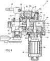
- FIG. 4 illustrates a schematic configuration of the clutch driving device 14 in an enlarged manner.
- the clutch driving device 14 includes the casing 40, the motor 50, a transfer mechanism 60, the assist mechanism 70, and a friction mechanism 80.
- FIG. 5 is a disassembled perspective view illustrating a part of the clutch driving device 14 in a disassembled state.
- the casing body 41 has a bottomed cylindrical shape extending in a cylinder axial direction. That is, the casing body 41 has an opening 41a.
- the casing body 41 accommodates the transfer mechanism 60 and the assist mechanism 70.
- a protrusion 46 is integrally formed on the bottom of the casing body 41.
- the cover 42 covers the opening 41a of the casing body 41.
- the cover 42 has storage space V therein.
- the friction mechanism 80 is disposed in the storage space V.
- the cover 42 includes a cover body 43 and a storage cover portion 44.
- the cover body 43 has a first recess 43a constituting a part of the storage space V.
- the storage cover portion 44 has a second recess 44a constituting the storage space V.
- the first recess 43a and the second recess 44a constitute the storage space V with the cover body 43 combined with the storage cover portion 44.
- the output shaft 63 of the transfer mechanism 60 described later penetrates a portion of the cover 42 different from the portion where the storage space V is formed.
- the output shaft 63 extends in the cylinder axial direction of the casing body 41 and outward of the casing 40. That is, the axial direction of the output shaft 63 coincides with the cylinder axial direction of the casing body 41.
- the motor compartment 45 is connected to the bottom of the casing body 41. Specifically, the motor compartment 45 is attached to the casing body 41 at a position that does not overlap the output shaft 63 when seen in the axial direction of the output shaft 63.
- the motor 50 generates an actuation driving force for actuating the clutch 13.
- the motor 50 is disposed in the motor compartment 45 such that an unillustrated rotating shaft extends along the axial direction.
- the transfer mechanism 60 includes an input shaft 61, an intermediate shaft 62, and the output shaft 63 (transfer member).
- the input shaft 61, the intermediate shaft 62, and the output shaft 63 are disposed in parallel.
- the input shaft 61 is an output shaft of the motor 50.
- the intermediate shaft 62 and the output shaft 63 are disposed in parallel with the output shaft of the motor 50. That is, the input shaft 61 and the intermediate shaft 62 extend along the axial direction of the output shaft 63.
- One end of the input shaft 61 in the axial direction is located in the motor compartment 45 housing the motor 50.
- the other end of the input shaft 61 in the axial direction is located in space defined by the casing body 41 and the cover 42.
- the other end of the input shaft 61 in the axial direction is provided with a gear 61a having a plurality of teeth arranged in the circumferential direction.
- the gear 61a is a spur gear.
- An intermediate gear 64 which is a spur gear, is provided to the intermediate shaft 62 to be rotatable together with the intermediate shaft 62.
- the intermediate gear 64 meshes with the gear 61a of the input shaft 61. Accordingly, rotation of the input shaft 61 is transferred to the intermediate shaft 62 through the intermediate gear 64. That is, the intermediate shaft 62 rotates in accordance with rotation of the input shaft 61.
- the intermediate shaft 62 is provided with a gear 62a having a plurality of teeth arranged in the circumferential direction at a position closer to a center in the axial direction than the one end of the intermediate shaft 62 rotatably supported on the casing body 41.
- the gear 62a is a spur gear closer to one side in the axial direction of the intermediate shaft 62 than the intermediate gear 64 is.
- the other end of the intermediate shaft 62 in the axial direction is rotatably supported on the cover 42.
- This other end of the intermediate shaft 62 in the axial direction is provided with a rotation transfer portion 83 of the friction mechanism 80 described later.
- the other end of the intermediate shaft 62 in the axial direction is provided with the rotation transfer portion 83 having a rectangular shape in cross section (see FIG. 13 ).
- a part of the intermediate shaft 62 including the rotation transfer portion 83 projects outward of the casing body 41.
- the rotation transfer portion 83 is inserted in a through hole 81a of a rotation body 81 of the friction mechanism 80 described later (see FIGS. 12 and 13 ).
- the friction mechanism 80 can be easily positioned in assembling the friction mechanism 80 to the intermediate shaft 62.
- assembly of the clutch driving device 14 can be performed easily.
- the friction mechanism 80 reduces rotation of the intermediate shaft 62 by a friction force.
- one end of the output shaft 63 in the axial direction is rotatably supported on the casing body 41, and a center portion of the output shaft 63 in the axial direction is rotatably supported on the cover 42.
- the other end of the output shaft 63 in the axial direction projects outward of the cover 42.
- This other end of the output shaft 63 in the axial direction is connected to the second arm 34 of the link mechanism 16 to be rotatable together with the second arm 34. Accordingly, rotation of the output shaft 63 is transferred to the clutch 13 through the link mechanism 16, and a clutch reaction force generated in the clutch 13 is input to the output shaft 63 through the link mechanism 16.
- An output gear 65 having a sector shape in plan view is provided to the output shaft 63 to be rotatable together with the output shaft 63.
- the output gear 65 is a spur gear and meshes with the gear 62a of the intermediate shaft 62. Accordingly, rotation of the intermediate shaft 62 is transferred to the output shaft 63 through the output gear 65. That is, the output shaft 63 rotates in accordance with rotation of the intermediate shaft 62.
- the output shaft 63 receives rotation of the intermediate shaft 62 of the clutch driving device 14 and also receives the clutch reaction force generated in the clutch 13.
- An end of the output gear 65 in the thickness direction is provided with a columnar pin 72 projecting in the thickness direction. That is, the pin 72 extends in the axial direction of the output shaft 63.
- the pin 72 is provided on one of the surfaces of the output gear 65 in the thickness direction at one side of the output shaft 63 in the axial direction. That is, the pin 72 is provided on the output gear 65 such that the pin 72 extends toward the bottom of the casing body 41 with the output shaft 63 and the output gear 65 disposed in the casing 40.
- the pin 72 rotates about the output shaft 63 with rotation of the output gear 65 that rotates together with the output shaft 63.
- the pin 72 contacts a first projection 71b of a spring 71 of the assist mechanism 70 described later.
- the pin 72 is rotatable with respect to the output gear 65. Thus, when the pin 72 moves while contacting the first projection 71b of the spring 71 as described later, the pin 72 moves relative to the first projection 71b while rotating.
- the assist mechanism 70 includes the spring 71 (auxiliary spring member) and the pin 72 described above.
- the spring 71 includes a wire material extending helically about an axis.
- the spring 71 has a cylindrical shape extending in the axial direction.
- the spring 71 is a so-called torsion spring that generates an elastic restoring force in a circumferential direction by twisting one end of the wire material relative to the other end of the wire material in the circumferential direction.
- the wire material for the spring 71 is wound clockwise from a winding start end (first projection 71b) that is one end of the wire material, as illustrated in FIG. 6 .
- the spring 71 is disposed in the casing body 41 to surround the input shaft 61 and the intermediate shaft 62 when seen in the axial direction of the output shaft 63.
- the input shaft 61 is inserted in the spring 71.
- One end of the intermediate shaft 62 in the axial direction is rotatably supported on a part of the casing body 41 (projection 46 described later) located inside the spring 71.
- the axis of the spring 71 is oriented in parallel with the output shaft 63.
- One end of the wire material constituting the spring 71 extends toward the output shaft 63.
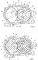
- FIG. 6 is a view of a schematic configuration of the assist mechanism 70 when seen in the axial direction of the output shaft 63.
- the columnar projection 46 disposed on the inner surface of the casing body 41 is located inside the spring 71.
- the protrusion 46 has an outer diameter smaller than the inner diameter of the spring 71.
- the protrusion 46 has a through opening 46a in which the input shaft 61 is inserted and an opening portion 46b in which one end of the intermediate shaft 62 in the axial direction is inserted.
- the spring 71 contacts a portion of the protrusion 46 close to the output shaft 63.
- a circumferential part of the protrusion 46 including the portion contacting with the spring 71 is provided with a metal contact plate 47 having an arc shape when seen in the axial direction of the output shaft 63. Both ends of the contact plate 47 are fixed to the projection 46c of the protrusion 46.
- the spring 71 contacts the contact plate 47.
- the contact plate 47 provided on the protrusion 46 can reduce damage of the protrusion 46 by the spring 71 when the spring 71 operates as described later.
- the spring 71 includes a cylindrical spring body 71a, a first projection 71b including one end of the wire material and extending radially outward from the spring body 71a, and a second projection 71c including the other end of the wire material and extending radially outward from the spring body 71a.
- the first projection 71b and the second projection 71c extend toward the output shaft 63 when seen in the axial direction of the output shaft 63.
- the first projection 71b contacts the pin 72 provided on the output gear 65 of the output shaft 63.
- the second projection 71c contacts the inner surface of the casing body 41.
- FIG. 7 suppose internal space of the casing body 41 is divided into two regions X and Y by an imaginary line M connecting the shaft center P of the output shaft 63 and a center Q (axis) of the spring 71 when seen in the axial direction of the output shaft 63 with the output gear 65 located at a position of a clutch disengaged state as described later, the first projection 71b and the second projection 71c are located in different regions in the two regions X and Y. That is, as illustrated in FIG.
- FIG. 7 is a schematic view corresponding to FIG. 6 and hatching the regions X and Y for description.
- the spring 71 in a case where one end of the wire material in the first projection 71b rotates in the circumferential direction of the spring 71 with the second projection 71c being in contact with the inner surface of the casing body 41, an elastic restoring force is generated in a direction in which the first projection 71b moves away from the second projection 71c. That is, in a case where the pin 72 rotates around the axis of the output shaft 63 with rotation of the output shaft 63 in such a manner that the clutch 13 changes from the clutch disengaged state to the engaged state, the first projection 71b of the spring 71 is pushed by the pin 72 in the circumferential direction of the spring 71.
- one end of the wire material of the spring 71 rotates about the axis of the spring 71 to approach the other end of the wire material in the second projection 71c.
- Such deformation of the spring 71 generates an elastic restoring force in the spring 71 in the circumferential direction of the spring 71 in a way in which the first projection 71b moves away from the second projection 71c.
- FIG. 8 shows schematic views illustrating relationship between the rotation position of the output gear 65 and deformation of the spring 71.
- the output shaft 63 and the output gear 65 are represented by dot-dot-dash lines, and only the pin 72 and the spring 71 are represented by continuous lines, for description.
- the regions X and Y are hatched for description, in a manner similar to FIG. 7 .
- FIG. 8 schematically illustrates regions X and Y defined by the imaginary line M for simplifying the drawings.
- FIG. 8(a) illustrates a rotation position of the output gear 65 when the clutch 13 is in the disengaged state.
- FIG. 8(b) illustrates a rotation position of the output gear 65 when the clutch 13 is in a half-clutch state (a state where sliding occurs between the clutch plates 23 and the friction plates 24 but a force in the rotation direction is transferred).
- FIG. 8(c) is a rotation position of the output gear 65 when the clutch 13 is in the engaged state.
- the pin 72 provided on the output gear 65 is located in the region X in the two regions X and Y obtained by dividing the internal space of the casing body 41 into two by the imaginary line M connecting the shaft center P of the output shaft 63 and the center Q of the spring 71, the pin 72 is in contact with the first projection 71b of the spring 71 in a portion close to the front end.
- a force exerted on the pin 72 by an elastic restoring force of the spring 71 is a force that causes the output gear 65 to rotate in a predetermined direction (also referred to as a rotation direction for clutch disengagement: a rotation direction indicated by an arrow of a dot-dot-dash line in FIG. 8(a) ) such that the clutch 13 is disengaged. That is, the spring 71 applies a torque to the output gear 65 through the pin 72 in the rotation direction for clutch disengagement.
- the first projection 71b of the spring 71 is not significantly displaced by the pin 72 in the circumferential direction of the spring 71.
- a force exerted on the pin 72 by the elastic restoring force of the spring 71 is smaller than those in the case of FIGS. 8(b) and 8(c) described later.
- the pin 72 receives a force in a direction with a magnitude indicated by a solid arrow in FIG. 8(a) from the first projection 71b of the spring 71.
- the first projection 71b of the spring 71 is displaced such that one end of the wire material is located in the region Y, that is, one end of the wire material in the first projection 71b approaches the other end of the wire material in the second projection 71c.
- the pin 72 approaches the spring body 71a while contacting the first projection 71b of the spring 71.
- the spring 71 is twisted in the circumferential direction. Consequently, the spring 71 generates an elastic restoring force in a direction in which the first projection 71b moves away from the second projection 71c.
- the elastic restoring force of the spring 71 is exerted on the pin 72 as indicated by the solid arrow in FIG. 8(b) . That is, the elastic restoring force of the spring 71 is transferred to the output gear 65 through the pin 72 as a torque in the rotation direction for clutch disengagement (the rotation direction indicated by the dot-dot-dash arrow in FIG. 8(b) ). Accordingly, a force of assisting in the rotation direction for clutch disengagement is transferred from the spring 71 to the output gear 65 through the pin 72. At this time, a force exerted on the pin 72 from the first projection 71b of the spring 71 is larger than that in the case of FIG. 8(a) .
- the output gear 65 is located at a rotation position illustrated in FIG. 8(c) , that is, in a case where the pin 72 is located in the region Y in the two regions X and Y, the first projection 71b of the spring 71 is displaced by the pin 72 to further approach the other end of the wire material in the second projection 71c. At this time, the pin 72 is located at a position closer to one end of the wire material than the position illustrated in FIG. 8(b) relative to the first projection 71b of the spring 71.
- the spring 71 is further twisted in the circumferential direction.
- An elastic restoring force of the spring 71 is exerted on the pin 72 as indicated by the solid arrow in FIG. 8(c) . That is, the elastic restoring force of the spring 71 is exerted on the output gear 65 through the pin 72 in a direction in which the output gear 65 rotates to engage the clutch 13 (hereinafter referred to as a rotation direction for clutch engagement: the rotation direction indicated by a dot-dot-dash arrow in FIG. 8(c) ). Accordingly, a force of assisting in the rotation direction for clutch engagement is transferred from the spring 71 to the output gear 65 through the pin 72.
- the contact point T between the pin 72 and the first projection 71b of the spring 71 straddles the imaginary line M connecting the shaft center P of the output shaft 63 and the center Q of the spring 71 when seen in the axial direction of the output shaft 63, in accordance with rotation of the output gear 65.
- a distance D between the contact point T and the center Q of the spring 71 varies in accordance with rotation of the output gear 65. That is, when seen in the axial direction of the output shaft 63, the distance D is smallest when the contact point T straddles the imaginary line M and increases as the distance to the contact point T from the imaginary line M increases.
- FIG. 9 shows relationships between a rotation angle (actuator rotation angle) of the output gear 65 and shaft torques: a torque in a rotation direction in which the torque is exerted on the output shaft 63 by a load in operating the clutch 13 (clutch load) (hereinafter referred to as a shaft torque); a shaft torque exerted on the output shaft 63 by an assist force of the assist mechanism 70; and the sum of a shaft torque generated on the output shaft 63 by a clutch load (clutch reaction force) and a shaft torque generated on the output shaft 63 by an assist force.
- the actuator rotation angle refers to a rotation angle of the output gear 65 with respect to an initial rotation position (the position illustrated in in FIG. 8(c) ) when seen in the axial direction of the output shaft 63 in a case where the output gear 65 rotates counterclockwise from the initial rotation position.
- a rotation range of the output gear 65 is defined by the inner surface of the casing body 41. That is, a position at which the output gear 65 contacts the inner surface of the casing body 41 when the output gear 65 rotates in the rotation direction for clutch engagement is a limit rotation position of the output gear 65 in the rotation direction for clutch engagement. A position at which the output gear 65 contacts the inner surface of the casing body 41 when the output gear 65 rotates in the rotation direction for clutch disengagement is a limit rotation position of the output gear 65 in the rotation direction for clutch disengagement.
- the actuator rotation angle increases in a case where the output gear 65 rotates in the order from FIG. 8(c), FIG. 8 (b), and FIG. 8 (a) when seen in the axial direction of the output shaft 63.
- the clutch load is equal to a reaction force (clutch reaction force) exerted on the clutch driving device 14 from the clutch spring 28 of the clutch 13, for example, while the clutch 13 operates.
- the clutch reaction force increases with an increase in the actuator rotation angle when the clutch 13 switches from the engaged state to the disengaged state.
- a shaft torque exerted on the output shaft 63 by the clutch reaction force varies to be at maximum at a predetermined actuator rotation angle as indicated by the solid line (solid line with "generated by clutch reaction force” in the drawing) in FIG. 9 , depending on a lever ratio determined based on relationship in the position and length between the first arm 33 and the second arm 34 in the link mechanism 16.
- the lever ratio refers to a ratio between a shaft torque exerted on the output shaft 63 of the clutch driving device 14 and a shaft torque exerted on the rotating shaft 31.
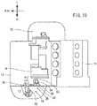
- the clutch driving device 14 is disposed relative to the engine 11 and the clutch 13 as illustrated in FIGS. 10 and 11 .
- FIG. 10 is a view schematically illustrating the engine 11, the clutch 13, and the clutch driving device 14 when seen from above the vehicle 1.
- FIG. 11 is a view schematically illustrating the engine 11, the clutch 13, and the clutch driving device 14 when seen from a side of the vehicle 1.
- FIGS. 10 and 11 other components are not shown for description of positional relationship among the engine 11, the clutch 13, and the clutch driving device 14, and the engine 11, the clutch 13, and the clutch driving device 14 are simplified in the illustration.
- arrow L represents a leftward direction of the vehicle 1.
- Arrow R in the drawings represents a rightward direction of the vehicle 1.
- Arrow RR in the drawings represents a rearward direction of the vehicle 1.
- Arrow U in the drawings represents an upward direction of the vehicle 1. The front, the rear, the left, and the right respectively refer to the front, the rear, the left, and the right when seen from a rider driving the vehicle 1.
- the clutch driving device 14 is disposed above the clutch 13 and behind the engine 11.
- the clutch driving device 14 is disposed above the clutch 13 and at the right of the clutch 13 when seen from above the vehicle 1.
- the clutch driving device 14 is disposed such that the axial direction of the output shaft 63 extends along the left-right direction (lateral direction) of the vehicle 1.
- the clutch 13 is disposed such that the axial direction of the rotating shaft 31 extends along the top-bottom direction (vertical direction) of the vehicle 1.
- the clutch driving device 14 is connected to the clutch 13 through the link mechanism 16. Specifically, one end of the first arm 33 of the link mechanism 16 is connected to the rotating shaft 31 and extends toward the left of the vehicle 1. One end of the second arm 34 of the link mechanism 16 is connected to the output shaft 63 of the clutch driving device 14 and extends toward the bottom of the vehicle 1.
- the adjustment mechanism 35 of the link mechanism 16 connects the first arm 33 and the second arm 34 to each other such that the first arm 33 and the second arm 34 are rotatable.
- the first adjustment member 91 and the second adjustment member 92 of the adjustment mechanism 35 are respectively connected to the plate-shaped first arm 33 and the plate-shaped second arm 34 in the thickness direction.
- the first adjustment member 91 and the second adjustment member 92 are disposed such that the axes of the rod-shaped connection members 94 and 95 are skewed to each other.
- the configuration of the link mechanism 16 is simplified.
- a lever ratio rt that is a ratio between a shaft torque exerted on the output shaft 63 of the clutch driving device 14 and a shaft torque exerted on the rotating shaft 31 is obtained by the equation below.
- the lever ratio rt is obtained on the assumption that a tilt of the adjustment mechanism 35 does not change when the link mechanism 16 operates.
- rt cos ⁇ ⁇ 2 / cos ⁇ ⁇ 1 ⁇ L 2 / L 1
- ⁇ 1 is an angle formed by the second arm 34 with respect to a reference line parallel to the axis of the rotating shaft 31 when the link mechanism 16 is seen from a side of the vehicle 1 (see FIG.
- ⁇ 2 is an angle formed by the first arm 33 with respect to a reference line parallel to the axis of the output shaft 63 when the link mechanism 16 is seen from above the vehicle 1 (see FIG. 10 ).
- L1 is a length of the second arm 34
- L2 is a length of the first arm 33.
- Equation (1) As the angle ⁇ 1 of the second arm 34 increases, cos ⁇ 1 decreases, and thus, the lever ratio rt increases. Accordingly, when the rotation angle of the output shaft 63 of the clutch driving device 14 increases, the lever ratio rt increases. That is, when the rotation angle (actuator rotation angle) of the output gear 65 that rotates together with the output shaft 63 increases, the lever ratio rt increases.
- the clutch reaction force increases as the actuator rotation angle increases, and in a case where the actuator rotation angle is large, the amount of increase in a clutch reaction force with respect to the amount of increase in the actuator rotation angle is small as compared to a case where the actuator rotation angle is small.
- a shaft torque generated on the output shaft 63 when the clutch reaction force is exerted on the output shaft 63 decreases as the lever ratio rt increases.
- the shaft torque decreases as the actuator rotation angle increases.
- the shaft torque generated on the output shaft 63 by the clutch reaction force increases with an increase in the actuator rotation angle in the case where the actuator rotation angle is small, whereas when the actuator rotation angle exceeds a predetermined actuator rotation angle, the shaft torque decreases with an increase in the actuator rotation angle. That is, the shaft torque varies and is at maximum at the predetermined actuator rotation angle.
- a range where the shaft torque exerted on the output shaft 63 is positive (larger than zero in FIG. 9 ) is a shaft torque range where the clutch 13 is engaged
- a range where the shaft torque exerted on the output shaft 63 is negative (smaller than zero in FIG. 9 ) is a shaft torque range where the clutch 13 is disengaged.
- the shaft torque exerted on the output shaft 63 by a clutch reaction force generated in operating the clutch 13 starts being generated at an actuator rotation angle at which the clutch 13 starts shifting from the engaged state to the disengaged state (S in FIG. 9 ).
- the shaft torque exerted on the output shaft 63 by the clutch reaction force is generated by a force that causes the output shaft 63 to rotate in a predetermined direction (hereinafter referred to as a rotation direction for clutch engagement) so as to engage the clutch 13.
- the clutch reaction force is generated by, for example, an elastic restoring force of the clutch spring 28 of the clutch 13.
- rotation (actuation driving force) of the motor 50 causes the rotation position of the output gear 65 to change such that the actuator rotation angle increases, that is, to change in the order of FIGS. 8(c), 8(b), and 8(a) .
- a force exerted on the pin 72 of the output gear 65 from the spring 71 changes parabolically and is at maximum at a predetermined actuator rotation angle.
- a shaft torque exerted on the output shaft 63 by an assist force of the clutch driving device 14 (indicated by the continuous line represented as "generated by assist force" in FIG. 9 ) changes parabolically and is also at maximum at the predetermined actuator rotation angle.
- the magnitude of the elastic restoring force of the spring 71 exerted on the pin 72 of the output gear 65 as an assist force in the rotation direction for clutch disengagement varies depending on the rotation position of the output gear 65. This is because a change of the contact point T between the first projection 71b of the spring 71 and the pin 72 along the first projection 71b in accordance with the rotation position of the output gear 65 causes the direction of a force exerted on the pin 72 from the first projection 71b to vary, and also causes the distance D between the contact point T between the pin 72 and the first projection 71b of the spring 71 and the center Q of the spring 71 to vary.
- the shaft torque exerted on the output shaft 63 by driving of the motor 50 and the assist mechanism 70, that is, the clutch driving device 14, is mainly a shaft torque that disengages the clutch 13 (shaft torque in the negative region in FIG. 9 ).
- the assist force is input to the output shaft 63 from the assist mechanism 70 of the clutch driving device 14 before the clutch reaction force is input from the clutch 13.
- the assist force input to the output shaft 63 from the assist mechanism 70 becomes zero after the clutch reaction force input from the clutch 13 becomes zero.
- a force transfer path between the output shaft 63 and the contact portion between the clutch plates 23 and the friction plates 24 is configured such that the timing of transfer of the clutch reaction force to the output shaft 63 and the timing of input of the assist force to the output shaft 63 are different.
- a predetermined gap is provided between the flange portion 29a of the push rod 29 and the pressure member 27. Accordingly, in a case where a force that moves the pressure member 27 away from the clutch boss 26 is exerted on the push rod 29 by the clutch driving device 14 through the link mechanism 16, the clutch reaction force is input to the output shaft 63 at the timing as described above.
- the timings of input of the assist force and the clutch reaction force to the output shaft 63 show the relationship as described above. That is, even in the case where the abrasion amount reaches the predetermined limit, in switching the clutch 13 from the engaged state to the disengaged state, the assist force is input to the output shaft 63 from the assist mechanism 70 of the clutch driving device 14 before the clutch reaction force is input from the clutch 13. On the other hand, in switching the clutch 13 from the disengaged state to the engaged state, the assist force input to the output shaft 63 from the assist mechanism 70 becomes zero after the clutch reaction force input from the clutch 13 becomes zero. Accordingly, even when the abrasion amount of the clutch plates 23 and the friction plates 24 reaches the predetermined limit, the clutch 13 can be smoothly switched to the engaged state or the disengaged state.
- the predetermined limit may be an abrasion amount of the clutch 13 in a case where the vehicle 1 is used normally (used expected at the time of design) or an abrasion amount when the clutch 13 starts slipping during travel of the vehicle 1, within a period of lifetime of the vehicle 1 expected at the time of design.
- the assist force is at maximum after start of input of the clutch reaction force to the output shaft 63 from the clutch 13.
- the shaft torque generated on the output shaft 63 by the clutch reaction force is at maximum at a predetermined actuator rotation angle under the influence of the lever ratio.
- an actuation driving force necessary for actuating the clutch can be effectively reduced by the assist force. Accordingly, the clutch 13 can be smoothly switched from the engaged state to the disengaged state.
- the assist force input to the output shaft 63 is at maximum before the clutch reaction force input to the output shaft 63 becomes zero. Accordingly, in a period before completion of engaging operation of the clutch 13, that is, a period in which the clutch 13 is in a half-clutch state, a sufficient assist force can be input to the link mechanism 16. Consequently, in the period in which the clutch 13 is in the half-clutch state, engaging operation of the clutch 13 can be smoothly performed with a small actuation driving force.
- a shaft torque as the sum of the shaft torque exerted on the output shaft 63 by the assist mechanism 70 and the shaft torque exerted on the output shaft 63 by the clutch reaction force generated in the clutch 13 has a small value relative to an actuator rotation angle, as indicated by the bold line in FIG. 9 . That is, the sum of the shaft torques is within a certain range in a half-clutch region illustrated in FIG. 9 (the range of the actuator rotation angle in the half-clutch state). Accordingly, the half-clutch state of the clutch 13 can be obtained in the output shaft 63 by a relatively small and stable shaft torque.
- the sum of the shaft torques is an actuation driving force of the motor 50 necessary for actuating the clutch 13.
- the clutch 13 can be easily switched from the engaged state to the disengaged state, and a stable half-clutch state can be obtained.
- FIG. 12 is a view illustrating the friction mechanism 80 in an enlarged manner.
- the friction mechanism 80 holds the intermediate shaft 62 in a stationary state by friction between the rotation body 81 and a pair of friction plates 82. Accordingly, even when driving of the motor 50 is stopped while the vehicle is stopped, for example, the friction mechanism 80 can hold a disengaged state of the clutch 13.
- the friction mechanism 80 includes the rotation body 81, the pair of friction plates 82, the rotation transfer portion 83 provided at one end of the intermediate shaft 62, and a spring 84.
- the friction mechanism 80 is disposed in the storage space V defined in the cover 42 of the clutch driving device 14.
- the friction mechanism 80 is disposed between the cover body 43 and the storage cover portion 44.
- the friction mechanism 80 is disposed such that the transfer mechanism 60 is located between the friction mechanism 80 and the motor 50 in the axial direction of the output shaft 63. Accordingly, the friction mechanism 80 can be made compact without interference with the motor 50.
- the pair of friction plates 82 is disposed at both sides in the thickness direction of the rotation body 81. That is, the pair of friction plates 82 and the rotation body 81 are stacked in the order of the friction plate 82, the rotation body 81, and the friction plate 82 in the thickness direction of the friction plates 82.
- Each of the friction plates 82 is a hollow disc member. At least one of both surfaces in the thickness of this hollow disc member contacting the rotation body 81 has a friction coefficient with which a predetermined friction force is obtained when the surface contacts the rotation body 81.
- each of the friction plates 82 is made of, for example, a stainless plate member whose surfaces are polished.
- the pair of friction plates 82 and the rotation body 81 are disposed in the first recess 43a provided in the cover body 43. One of the pair of friction plates 82 is in contact with the inner surface of the first recess 43a of the cover body 43.
- each of the pair of friction plates 82 has a plurality of positioning protrusions 82a on an outer peripheral portion thereof.
- the positioning protrusions 82a are disposed in positioning recesses 43b formed in the inner surface of the first recess 43a with the pair of friction plates 82 disposed in the first recess 43a of the cover body 43. This configuration can reduce rotation of the pair of friction plates 82 together with the rotation body 81.
- the rotation body 81 is a disc-shaped metal member. As illustrated in FIG. 13 , the rotation body 81 has a through hole 81a (opening portion) formed in a center portion (rotation center) of the rotation body 81 and penetrating the rotation body 81 in the thickness direction.
- the through hole 81a is rectangular when seen in the thickness direction of the rotation body 81.
- the rotation transfer portion 83 disposed at one end of the intermediate shaft 62 penetrates the through hole 81a.
- the rotation body 81 has a contact portion 81b located in an outer peripheral portion of the disc-shaped rotation body 81 when seen in the thickness direction, and the contact portion 81b contacts the pair of friction plates 82.
- the contact portion 81b has a thickness larger than the thickness of a center portion of the rotation body 81. That is, the contact portion 81b projects from the center portion of the rotation body 81 in the thickness direction of the rotation body 81. Accordingly, the contact portion 81b of the rotation body 81 contacts the pair of friction plates 82 with the rotation body 81 disposed between the pair of friction plates 82.
- the rotation transfer portion 83 is disposed at an end of the intermediate shaft 62 in the axial direction.
- the rotation transfer portion 83 has a columnar shape that is rectangular in cross section.
- the rotation transfer portion 83 is formed to be insertable in the through hole 81a of the rotation body 81. Accordingly, in a case where the intermediate shaft 62 rotates with the rotation transfer portion 83 inserted in the through hole 81a of the rotation body 81, rotation of the intermediate shaft 62 is transferred to the rotation body 81 through the rotation transfer portion 83.
- the friction mechanism 80 generates a friction force in a direction opposite to the rotation direction of rotation transferred by the transfer mechanism 60.
- character Z is an axis of the intermediate shaft 62.
- the axial direction in which this axis Z extends is the same direction as the axial direction of the output shaft 63.
- the expression that the direction of the axis (axial direction) of the intermediate shaft 62 is the same as the axial direction of the output shaft 63 includes a case where these the axial direction of the intermediate shaft 62 is not completely the same as the axial direction of the output shaft 63 as long as rotation can be transferred between the intermediate shaft 62 and the output shaft 63.
- the rotation transfer portion 83 provided in the intermediate shaft 62 is inserted in the through hole 81a of the rotation body 81 described above so that friction mechanism 80 is thereby separated from a transfer path of power from the input shaft 61 to the output shaft 63 in the transfer mechanism 60. That is, the friction mechanism 80 is not included in the transfer mechanism 60, but is separated from the transfer mechanism 60.
- the spring 84 includes a wire material extending helically about the axis.
- the spring 84 has a cylindrical shape extending in the axial direction.
- the spring 84 is a compression spring that generates an elastic restoring force when being compressed in the axial direction.
- the spring 84 is disposed in the storage cover portion 44 such that the axial direction coincides with the axial direction of intermediate shaft 62. That is, the axis of the spring 84 extends in the same direction as the axial direction of the output shaft 63.
- the spring 84 is disposed with respect to the pair of friction plates 82 and the rotation body 81 such that the axis of the spring 84 coincides with the thickness direction of the pair of friction plates 82 and the rotation body 81.
- One end toward one direction along the axis of the spring 84 contacts one of the pair of friction plates 82 toward the other end in the axial direction. That is, the pair of friction plates 82 and the rotation body 81 are located closer to the rotation transfer portion 83 than the spring 84 is.
- one of the pair of friction plates 82 toward the one direction along the axis contacts the inner surface of the first recess 43a of the cover body 43. Accordingly, the spring 84 applies a force on the pair of friction plates 82 and the rotation body 81 in the thickness direction.
- the pair of friction plates 82 and the rotation body 81 are pressed in the thickness direction between the spring 84 and the inner surface of the first recess 43a of the cover body 43.
- the sum of the shaft torque generated by an assist force of the clutch driving device 14 and the shaft torque generated by a clutch reaction force of the clutch 13 is a shaft torque exerted on the output shaft 63 of the clutch driving device 14.
- a range of a shaft torque with which rotation of the rotation body 81 and the intermediate shaft 62 stops by the friction force between the rotation body 81 and the pair of friction plates 82 is indicated by dot-dot-dash lines.
- the clutch plates 23 and the friction plates 24 are subjected to a force with which the clutch plates 23 and the friction plates 24 are pushed against each other by the clutch spring 28 such that the clutch 13 is engaged.
- the friction mechanism 80 with the configuration described above provided in the clutch driving device 14 stops operation of the transfer mechanism 60 of the clutch driving device 14 even while driving of the motor 50 is stopped. Accordingly, the clutch 13 does not operate.
- a self-lock mechanism capable maintaining an operation state (the half-clutch state or the disengaged state) of the clutch 13 without change can be obtained.
- the self-lock mechanism as described above can be obtained by setting a clutch reaction force and an assist force to be input to the output shaft 63 of the clutch driving device 14 such that the sum of the shaft torques generated on the output shaft 63 is the predetermined value or less as illustrated in FIG. 9 .
- insertion of the rotation transfer portion 83 of the intermediate shaft 62 into the through hole 81a of the rotation body 81 allows displacement of the rotation body 81 relative to the intermediate shaft 62 in directions except the rotation direction. Accordingly, even in a case where the intermediate shaft 62 tilts, for example, rotation of the intermediate shaft 62 can be transferred to the rotation body 81 with a tilt of the rotation body 81 prevented. In this manner, it is possible to rotate the rotation body 81 by the intermediate shaft 62 while ensuring contact of the rotation body 81 with the pair of friction plates 82.
- the rotation body 81, the friction plates 82, and the spring 84 of the friction mechanism 80 assembled in the cover 42 can be attached to the inside of the casing body 41. As a result, workability in assembly of the friction mechanism 80 can be enhanced.
- the casing housing the friction mechanism 80 is constituted by a part of the cover 42 of the clutch driving device 14. This makes the entire configuration of the clutch driving device 14 compact.
- the clutch unit 17 includes the clutch 13, the motor 50, the output shaft 63, and the spring 71.
- the clutch 13 includes the plurality of clutch plates 23 and the plurality of friction plates 24 that transfer a torque by a friction force, and the clutch spring 28 connecting the plurality of clutch plates 23 and the plurality of friction plates 24 to one another by an elastic restoring force.
- the clutch 13 is provided to be switchable between an engaged state where a torque is transferred and a disengaged state where the torque is interrupted.
- the motor 50 generates an actuation driving force for actuating the clutch 13.
- the output shaft 63 transfers the actuation driving force generated by the motor 50 to the clutch 13, and receives the elastic restoring force of the clutch spring 28 from the clutch 13 as a clutch reaction force.
- the spring 71 inputs an assist force for assisting the actuation driving force to the output shaft 63.
- the assist force is input to the output shaft 63 from the spring 71 before the clutch reaction force is input from the clutch 13.
- the assist force input to the output shaft 63 from the spring 71 becomes zero.
- the clutch 13 can be smoothly switched to the engaged state or the disengaged state to cope with the abrasion of the clutch plates 23 and the friction plates 24, without compensation for the abrasion.
- the clutch 13 can be smoothly switched to the engaged state or the disengaged state.
- the assist force input to the output shaft 63 from the spring 71 is at maximum after the clutch reaction force is input to the output shaft 63 from the clutch 13.
- the clutch reaction force input to the output shaft 63 from the clutch 13 increases as the disengaging operation of the clutch 13 progresses.
- the assist force is at maximum after input of the clutch reaction force to the output shaft 63 from the clutch 13. Accordingly, even when the clutch reaction force input from the clutch 13 to the output shaft 63 increases with the progress of the disengaging operation of the clutch 13, a sufficient assist force can be input to the output shaft 63. As a result, the clutch 13 can be smoothly switched from the engaged state to the disengaged state.
- the assist force input from the spring 71 to the output shaft 63 is at maximum before the clutch reaction force input to the output shaft 63 from the clutch 13 becomes zero.
- the assist force is input to the output shaft 63 from the assist mechanism 70 of the clutch driving device 14 before the clutch reaction force is input from the clutch 13.
- the assist force input to the output shaft 63 from the assist mechanism 70 becomes zero after the clutch reaction force input from the clutch 13 becomes zero.
- the predetermined gap is provided between the flange portion 29a of the push rod 29 and the pressure member 27.
- the adjustment mechanism 35 of the link mechanism 16 may be adjusted to cause the clutch reaction force and the assist force to be exerted on the output shaft 63 as described above.
- the adjustment mechanism 35 of the link mechanism 16 may be used.
- the adjustment mechanism 35 makes the distance between the first arm 33 and the second arm 34 larger than that in a normal setting so that a shaft torque as shown in FIG. 9 can be obtained as a shaft torque generated in the output shaft 63 by the clutch reaction force.
- a typical abrasion compensation device is not provided.
- the typical abrasion compensation device may be provided in the clutch 13. That is, the clutch 13 may include a mechanism that adjusts the position of the pressure member 27 in order to prevent the value S of the actuator rotation angle from changing in FIG. 9 even when the clutch plates 23 and the friction plates 24 are abraded.
- the abrasion compensation device may have any configuration as long as the value S in FIG. 9 can be corrected to reduce the influence of abrasion of the clutch plates 23 and the friction plates 24 on operation of the clutch 13 in the case where the abrasion occurs.
- the push rod 29 of the clutch 13 moves in the axial direction of the main shaft 15 by the rotating shaft 31 connected to the link mechanism 16.
- an output of the clutch driving device 14 may be directly transferred to the rotating shaft 31 without using the link mechanism 16.
- the first transfer gear 166 is provided to the output shaft 63 of the clutch driving device 114 to be rotatable together with the output shaft 63.
- the second transfer gear 167 is provided to the other end of the rotating shaft 31 in the axial direction to be rotatable together with the rotating shaft 31.
- the first transfer gear 166 and the second transfer gear 167 mesh each other in a casing 140 of the clutch driving device 114.
- the clutch driving device 114 includes no friction mechanism.
- the clutch driving device 114 may include a friction mechanism with a configuration similar to that of the clutch driving device 14 of this embodiment.
- the output shaft 63 is used as an example of a transfer member that receives an output of the clutch driving device 14 and a clutch reaction force generated in the clutch 13.
- the transfer portion member may be a component except the output shaft 63 as long as the component receives outputs of the motor 50 and the assist mechanism 70 and a clutch reaction force generated in the clutch 13, as exemplified by the output gear 65 and the rotating shaft 31.
- the assist force is input to the output shaft 63 from the spring 71 before input of the clutch reaction force from the clutch 13, whereas in switching the clutch 13 from the disengaged state to the engaged state, the assist force from the spring 71 becomes zero after the clutch reaction force input to the output shaft 63 from the clutch 13 becomes zero.
- this relationship does not need to be satisfied at the time when the abrasion amount of the clutch plates 23 and the friction plates 24 reaches the predetermined limit.
- the assist force input from the spring 71 to the output shaft 63 is at maximum after input of the clutch reaction force from the clutch 13 to the output shaft 63.
- the assist force input from the spring 71 to the output shaft 63 may be at maximum before or at the time of start of input of the clutch reaction force from clutch 13 to the output shaft 63.
- the assist force input from the spring 71 to the output shaft 63 is at maximum before the clutch reaction force input to the output shaft 63 from the clutch 13 becomes zero.
- the assist force input from the spring 71 to the output shaft 63 may be at maximum after or at the time when the clutch reaction force input to the output shaft 63 from the clutch 13 becomes zero.
- the clutch driving device 14 transfers rotation from the input shaft 61 to the output shaft 63 through the intermediate shaft 62.
- the input shaft 61 and the output shaft 63 may be configured to transfer rotation directly by a gear.
- the clutch driving device 14 includes the friction mechanism 80 as an example of a self-lock mechanism.
- functions of the self-lock may be achieved by another configuration.
- the clutch driving device 14 may not include a self-lock mechanism such as the friction mechanism 80.
- the clutch driving device 14 includes the motor 50 that generates an actuation driving force for actuating the clutch 13.
- the clutch driving device 14 may include another driving source capable of generating the actuation driving force.
- the gears 61a and 62a, the intermediate gear 64, and the output gear 65 that transfer rotation of the input shaft 61 to the output shaft 63 are spur gears.
- at least one of the gears may be a spur gear and the other may be gears of other shapes. All the gears may be gears except spur gears.
- the input shaft 61 is provided with the gear 61a
- the intermediate shaft 62 is also provided with the gear 62a.
- the gear 61a may be integrally provided to the input shaft 61 or may be a member separated from the input shaft 61.
- the gear 62a may be integrally provided to the intermediate shaft 62 or may be member separated from the intermediate shaft 62.
- the spring 71 of the assist mechanism 70 includes the first projection 71b projecting radially outward.
- the first projection 71b contacts the pin 72 provided on the output gear 65. That is, in the embodiment described above, the contact point T between the first projection 71b and the pin 72 is located radially outside the spring 71.
- the contact point T may be located radially inside the spring. That is, the first projection may extend radially inward of the spring.
- the output gear may be located inside the spring or outside the spring when seen in the axial direction of the output shaft 63.
- the pin 72 provided on the output gear 65 directly contacts the first projection 71b of the spring 71 in the assist mechanism 70.
- the output gear may be provided with a link mechanism so that a part of the link mechanism contacts the first projection 71b.
- the spring 71 of the assist mechanism 70 includes the first projection 71b and the second projection 71c extending toward the output shaft 63 when seen in the axial direction of the output shaft 63 in a state where the spring 71 is disposed inside the casing 40.
- the second projection 71c may extend in a direction different from the first projection 71b as long as the second projection 71c can contact the inner surface of the casing body 41 so that the spring 71 is twisted in the circumferential direction when the first projection 71b is displaced by rotation of the output gear 65.
- the assist mechanism 70 when the spring 71 of the assist mechanism 70 is deformed such that the first projection 71b approaches the second projection 71c, the spring 71 is twisted in the circumferential direction to generate an elastic restoring force.
- the assist mechanism 70 outputs this elastic restoring force as an assist force for driving of the clutch 13.
- the assist mechanism may be configured to output an elastic restoring force generated when the spring is deformed to cause the first projection to move away from the second projection as an assist force for actuating the clutch 13.
- the clutch driving device 14 includes the assist mechanism 70 including the spring 71 as a torsion spring.
- the assist mechanism 70 may be constituted by a configuration except the spring 71 as a torsion spring as long as the assist mechanism 70 is capable of outputting an assist force for driving of the clutch 13.
- the cylinder axial direction of the casing 40, the axial direction of the input shaft 61, the intermediate shaft 62, and the output shaft 63, and the axial direction of the springs 71 and 84 are the same.
- the cylinder axial direction of the casing 40, the axial direction of the input shaft 61 and the output shaft 63, and the axial direction of the springs 71 and 84 may be different from one another.
- the vehicle 1 may have any configuration such as a three-wheeled vehicle or a four-wheeled vehicle as long as the configuration includes a clutch driving device for driving a clutch.
Landscapes
- Engineering & Computer Science (AREA)
- General Engineering & Computer Science (AREA)
- Mechanical Engineering (AREA)
- Physics & Mathematics (AREA)
- Electromagnetism (AREA)
- Mechanical Operated Clutches (AREA)
Abstract
Description
- The present teaching relates to a clutch unit capable of transferring and interrupting a torque.
- A known clutch unit includes a clutch and an actuator that generates a force for actuating the clutch (hereinafter referred to as an actuation driving force). Such a clutch unit is capable of switching the clutch between an engaged state and a disengaged state by using an actuation driving force generated by the actuator. The engaged state of the clutch refers to a state where the clutch transfer a torque, and the disengaged state of the clutch refers to a state where a torque is interrupted by the clutch.
- Such a clutch unit as described above has a known configuration including an auxiliary spring member in order to assist a switching operation of the clutch by the actuator. For example, a friction clutch disclosed in
Patent Document 1 includes a clutch engagement device, an electric motor, an elastic auxiliary means (coil spring), and a linkage. - The clutch engagement device of the friction clutch disclosed in
Patent Document 1 includes a friction disc, a friction lining, a flywheel, a thrust plate, and a diaphragm. The friction lining is disposed between the flywheel and the thrust plate, and is supported on an outer peripheral portion of the friction disc. In normal operation (while no force is exerted on the diaphragm from the electric motor), a force is exerted on the thrust plate from the diaphragm. Accordingly, the friction lining is located between the flywheel and the thrust plate. Thus, the friction clutch disclosed inPatent Document 1 is in the engaged state in normal operation. In the following description, the clutch unit that is in the engaged state while no force is exerted on the clutch from the actuator will be referred to as a normally closed clutch unit. - In the friction clutch disclosed in
Patent Document 1, the diaphragm is connected to an electric motor through the linkage. For example, in switching the friction clutch disclosed inPatent Document 1 from the engaged state to the disengaged state, an actuation driving force generated by the electric motor is transferred to the diaphragm through the linkage. Although detailed description is omitted, a center portion of the diaphragm is depressed by the linkage. At this time, an outer peripheral portion of the diaphragm (a portion in contact with the thrust plate) moves away from the thrust plate. Accordingly, a force exerted on the thrust plate from the diaphragm decreases. Thus, a pressing force of the thrust plate against the friction lining decreases. Consequently, the friction clutch is in a disconnected state. - In the friction clutch disclosed in
Patent Document 1, the linkage is also subjected to a force generated by the elastic auxiliary means (hereinafter referred to as an assist force) in addition to the actuation driving force generated by the electric motor. Hereinafter, forces generated by the diaphragm, the electric motor, and the elastic auxiliary means in the friction clutch ofPatent Document 1 will be briefly described with reference to the drawings. -
FIG. 15 is a graph for describing forces generated by the diaphragm, the electric motor, and the elastic auxiliary means in the friction clutch described inPatent Document 1. InFIG. 15 , the ordinate represents a force exerted on the linkage, and the abscissa represents a travel distance of the linkage (travel distance of a contact portion between the linkage and the diaphragm). InFIG. 15 , a curve C1 represents a force exerted on the linkage from the diaphragm (reaction force exerted on the linkage from the diaphragm), a curve C2 represents an assist force exerted on the linkage from the elastic auxiliary means, and a curve C3 represents an actuation driving force exerted on the linkage from the electric motor. InFIG. 15 , a force exerted in a direction in which the friction clutch is switched to an engaged state is represented as a positive value, and a force exerted in a direction in which the friction clutch is switched to a disengaged state is represented as a negative value. The travel distance is 0 (zero) when the friction clutch is switched to the engaged state, and increases as the linkage moves in the direction in which the friction clutch is switched to the disengaged state. - As illustrated in
FIG. 15 , in the friction clutch disclosed inPatent Document 1, the assist force generated by the elastic auxiliary means is input to the linkage (C2 inFIG. 15 ) so as to counter a reaction force exerted on the linkage from the diaphragm (C1 inFIG. 15 ). That is, in switching the friction clutch to the engaged state or the disengaged state by the electric motor, the assist force generated by the elastic auxiliary means is exerted on the linkage as a force of assisting the electric motor. Accordingly, in the friction clutch disclosed inPatent Document 1, the friction clutch can be switched to the engaged state or the disengaged state with a small actuation driving force. - In the clutch unit, a member that transfers a torque by a friction force (hereinafter referred to as a torque transfer member) is abraded with an operating time. In the friction clutch disclosed in
Patent Document 1, the friction lining serving as a torque transfer member is abraded with an operating time. - In the friction clutch disclosed in
Patent Document 1, when the friction lining is abraded, the thrust plate moves toward the flywheel. The movement of the thrust plate toward the flywheel causes the shape of the diaphragm to change. Accordingly, in switching the friction clutch to the engaged state or the disengaged state, the magnitude of a reaction force exerted on the linkage from the diaphragm varies. That is, the magnitude of the force represented by the curve C1 inFIG. 15 varies. In this case, the magnitude of an actuation driving force that needs to be generated by the electric motor (see the curve C3 inFIG. 15 ) also varies. When the abrasion amount of the friction lining increases so that the diaphragm deforms greatly, the actuation driving force that needs to be generated by the electric motor also changes greatly. To cope with such a change in force, an electric motor having a large output needs to be provided. In this case, a small-size electric motor cannot be used, and thus, size reduction of the friction clutch is difficult. - In view of this, in the friction clutch disclosed in
Patent Document 1, the clutch engagement device is provided with a device for taking up abrasion (abrasion compensation device). The abrasion compensation device is configured to constantly maintain the diaphragm at the same position while the friction clutch is in the engaged state. This configuration can suppress a change in magnitude of the reaction force exerted on the linkage from the diaphragm. - Patent Document 1: Japanese Unexamined Patent Application Publication (Translation of PCT Application) No.
2000-501826 - Through the study of inventors of the present teaching on the normally closed clutch unit, there has arisen a demand for coping with abrasion of the torque transfer member by using a configuration different from that of the abrasion compensation device as described above for the following reasons.
- That is, if it is possible to cope with abrasion of the torque transfer member with the configuration different from the abrasion compensation device as described above, the clutch unit can be reduced in cost and size.
- In view of this, an object of the present teaching is to obtain a clutch unit capable of coping with abrasion of a torque transfer member with a configuration different from an abrasion compensation device proposed to date.
- The inventors of the present teaching have conducted various studies on abrasion of a torque transfer member in a normally closed clutch unit. Specifically, study on abrasion of the torque transfer member was conducted for a clutch unit including a clutch including a torque transfer member, an actuator that generates an actuation driving force for actuating the clutch, an auxiliary spring member that generates an assist force for assisting the actuator, and a transfer member for transferring the actuation driving force and the assist force to the clutch. In this study, investigation was conducted on a configuration capable of coping with abrasion of the torque transfer member without compensating for abrasion of the torque transfer member.
- The inventors of the present teaching first closely investigated a phenomenon occurring in the clutch, the actuator, and the transfer member in switching the clutch to an engaged state or a disengaged state in a normally closed clutch unit.
- Consequently, in switching the clutch from the engaged state to the disengaged state, the timing when an input of a clutch reaction force (a reaction force generated by, for example, the clutch spring) to the transfer member from the clutch starts becomes earlier by abrasion of the torque transfer member. More specifically, it was found that in switching the clutch from the engaged state to the disengaged state, abrasion of the torque transfer member causes a clutch reaction force to be input to the transfer member from the clutch before the assist force generated by the auxiliary spring member is input to the transfer member. Thus, after start of input of the clutch reaction force to the transfer member from the clutch, a period in which the assist force cannot be used for actuating the clutch occurs.
- On the other hand, in switching the clutch from the disengaged state to the engaged state, the timing when the clutch reaction force input to the transfer member from the clutch reaches zero becomes later by abrasion of the torque transfer member. More specifically, it was found that in switching the clutch from the disengaged state to the engaged state, abrasion of the torque transfer member causes the assist force input from the auxiliary spring member to the transfer member to be zero before the clutch reaction force input to the transfer member from the clutch becomes zero. Thus, before the clutch reaction force input to the transfer member from the clutch becomes zero, a period in which the assist force cannot be used occurs.
- As described above, when the torque transfer member is abraded, a period in which the assist force of the auxiliary spring member cannot be used occurs after start of disengaging operation of the clutch and before completion of engaging operation of the clutch.
- Here, if the period in which the assist force cannot be used occurs after start of disengaging operation of the clutch, in order to disengage the clutch, a large actuation driving force needs to be generated by the actuator so as to cope with the clutch reaction force of the clutch. In this case, a large-size actuator is needed, which is not favorable in terms of size reduction of the clutch unit.
- In addition, after the start of disengaging operation of the clutch and before the completion of engaging operation of the clutch, the clutch is temporarily in a half-clutch state. In particular, in switching the clutch from the disengaged state to the engaged state, the clutch needs to be controlled precisely in the period in which the clutch is in the half-clutch state. However, when the torque transfer member is abraded as described above, a period in which the assist force of the auxiliary spring member cannot be used occurs before the completion of engaging operation of the clutch. When the clutch changes to the half-clutch state in this period, it is necessary to adjust the actuation driving force precisely while generating a large actuation driving force by the actuator. This is not favorable because of difficulty in control the actuator as well as necessity for providing a large-sized actuator in this case.
- In view of this, the inventors of the present teaching have studied a configuration of a clutch unit that can prevent occurrence of a period in which the assist force cannot be used after start of disengaging operation of the clutch and before completion of engaging operation of the clutch even when the torque transfer member is abraded. As a result, the inventors finally found that the clutch unit only needs to be configured as follows.
- First, the clutch unit is configured to allow the assist force to be input from the auxiliary spring member to the transfer member before the clutch reaction force is input to the transfer member from the clutch in switching the clutch from the engaged state to the disengaged state. In this case, in switching the clutch to the disengaged state, even if the timing when input of the clutch reaction force to the transfer member from the clutch starts becomes earlier, it is possible to suppress input of the clutch reaction force to the transfer member from the clutch before the assist force is input to the transfer member. That is, it is possible to suppress occurrence of a period in which the assist force cannot be used before start of disengaging operation of the clutch even if the torque transfer member is abraded.
- In addition, the clutch unit only needs to be configured to allow the assist force input to the transfer member from the auxiliary spring member to be zero after the clutch reaction force input to the transfer member from the clutch becomes zero in switching the clutch from the disengaged state to the engaged state. In this case, even if the timing when the clutch reaction force input to the transfer member from the clutch reaches zero becomes later in switching the clutch to the engaged state, it is possible to suppress a decrease of the assist force input to the transfer member to zero before the clutch reaction force input to the transfer member from the clutch becomes zero. That is, it is possible to suppress occurrence of a period in which the assist force cannot be used before completion of engaging operation of the clutch even when the torque transfer member is abraded.
- Based on the foregoing findings, the inventors arrived at a configuration described below.
- A clutch unit according to one embodiment of the present teaching includes: a clutch including a plurality of torque transfer members that transfer a torque by a friction force and a clutch spring that connects the plurality of torque transfer members to one another by an elastic restoring force, the clutch being switchable to an engaged state where a torque is transferred and a disengaged state where a torque is interrupted; an actuator that generates an actuation driving force for actuating the clutch; a transfer member that transfers the actuation driving force generated by the actuator to the clutch and receives the elastic restoring force of the clutch spring from the clutch as a clutch reaction force; and an auxiliary spring member that inputs an assist force for assisting the actuation driving force to the transfer member, wherein in switching the clutch from the engaged state to the disengaged state, the assist force is input to the transfer member from the auxiliary spring member before the clutch reaction force is input to the transfer member from the clutch, and in switching the clutch from the disengaged state to the engaged state, after the clutch reaction force input to the transfer member from the clutch becomes zero, the assist force input to the transfer member from the auxiliary spring member becomes zero.
- In the clutch unit, in switching the clutch to the engaged state or the disengaged state, the transfer member receives not only the clutch reaction force exerted from the clutch but also the assist force generated by the auxiliary spring member. Accordingly, an actuation driving force necessary for switching the clutch to the engaged state or the disengaged state can be reduced.
- In switching the clutch from the engaged state to the disengaged state, the transfer member receive the assist force from the auxiliary spring member before receiving the clutch reaction force from the clutch. In this case, in switching the clutch from the engaged state to the disengaged state, even if the timing of input of the clutch reaction force to the transfer member from the clutch becomes earlier, it is possible to suppress input of the clutch reaction force to the transfer member from the clutch before the assist force is input to the transfer member. That is, it is possible to prevent occurrence of a period in which the assist force cannot be used before start of disengaging operation of the clutch even if the torque transfer member is abraded.
- In addition, in switching the clutch from the disengaged state to the engaged state, the assist force input to the transfer member from the auxiliary spring member becomes zero after the clutch reaction force input to the transfer member from the clutch becomes zero. In this case, even if the timing when the clutch reaction force input to the transfer member from the clutch reaches zero becomes later in switching the clutch from the disengaged state to the engaged state, it is possible to suppress a decrease of the assist force input to the transfer member to zero before the clutch reaction force input to the transfer member from the clutch becomes zero. That is, it is possible to suppress occurrence of a period in which the assist force cannot be used before completion of engaging operation of the clutch even when the torque transfer member is abraded. In this case, it is not necessary to generate a large actuation driving force by a motor or the like in a period before completion of engaging operation of the clutch, that is, a period in which the clutch is in a half-clutch state. Accordingly, the actuation driving force can be adjusted easily.
- In the manner described above, in the clutch unit described above, even when the torque transfer members are abraded, the clutch can be smoothly switched to the engaged state or the disengaged state to cope with the abrasion without compensation for the abrasion.
- In another aspect, the clutch unit according to the present teaching preferably includes the following configuration, in a state where an abrasion amount of the torque transfer member reaches a predetermined limit, in switching the clutch from the engaged state to the disengaged state, the assist force is input to the transfer member from the auxiliary spring member before the clutch reaction force is input to the transfer member from the clutch, and in switching the clutch from the disengaged state to the engaged state, after the clutch reaction force input to the transfer member from the clutch becomes zero, the assist force input to the transfer member from the auxiliary spring member becomes zero.
- Accordingly, even when the abrasion amount of the torque transfer members reaches the predetermined limit, the clutch can be smoothly switched to the engaged state or the disengaged state.
- In another aspect, the clutch unit according to the present teaching preferably includes the following configuration. in switching the clutch from the engaged state to the disengaged state, the assist force input to the transfer member from auxiliary spring member is at maximum after start of input of the clutch reaction force to the transfer member from the clutch.
- In general, in a predetermined period immediately after start of disengaging operation of the clutch, the clutch reaction force input to the transfer member from the clutch increases as the disengaging operation of the clutch progresses. On the other hand, in the configuration described above, the assist force is at maximum after input of the clutch reaction force to the transfer member from the clutch starts. Accordingly, even when the clutch reaction force input from the clutch to the transfer member increases with the progress of the disengaging operation of the clutch, a sufficient assist force can be input to the transfer member. As a result, the clutch can be smoothly switched from the engaged state to the disengaged state.
- In another aspect, the clutch unit according to the present teaching preferably includes the following configuration. In switching the clutch from the disengaged state to the engaged state, the assist force input to the transfer member from auxiliary spring member is at maximum before input of the clutch reaction force to the transfer member from the clutch becomes zero.
- Accordingly, in a period before completion of engaging operation of the clutch, that is, a period in which the clutch is in a half-clutch state, a sufficient assist force can be input to the transfer member. Consequently, in the period in which the clutch is in the half-clutch state, engaging operation of the clutch can be smoothly performed with a small actuation driving force.
- A vehicle according to one embodiment of the present teaching includes a clutch unit including any one of the configurations described above.
- The terminology used herein is for the purpose of describing particular embodiments only and is not intended to be limiting to the invention.
- As used herein, the term "and/or" includes any and all combinations of one or more of the associated listed items.
- It will be further understood that the terms "including," "comprising" or "having" and variations thereof when used in this specification, specify the presence of stated features, steps, operations, elements, components, and/or their equivalents but do not preclude the presence or addition of one or more other features, steps, operations, elements, components, and/or groups thereof.
- It will be further understood that the terms "mounted," "connected," "coupled," and/or their equivalents are used broadly and encompass both direct and indirect mounting, connecting and coupling. Further, "connected" and "coupled" are not restricted to physical or mechanical connections or couplings, and can include electrical connections or couplings, whether direct or indirect.
- Unless otherwise defined, all terms (including technical and scientific terms) used herein have the same meaning as commonly understood by one having ordinary skill in the art to which this invention belongs.
- It will be further understood that terms, such as those defined in commonly used dictionaries, should be interpreted as having a meaning that is consistent with their meaning in the context of the relevant art and the present disclosure and will not be interpreted in an idealized or overly formal sense unless expressly so defined herein.
- In describing the invention, it will be understood that a number of techniques and steps are disclosed. Each of these has individual benefit and each can also be used in conjunction with one or more, or in some cases all, of the other disclosed techniques.
- Accordingly, for the sake of clarity, this description will refrain from repeating every possible combination of the individual steps in an unnecessary fashion. Nevertheless, the specification and claims should be read with the understanding that such combinations are entirely within the scope of the invention and the claims.
- Embodiments of a clutch unit and a vehicle according to present teaching are discussed herein.
- In the following description, for purposes of explanation, numerous specific details are set forth in order to provide a thorough understanding of the present invention. It will be evident, however, to one skilled in the art that the present invention may be practiced without these specific details.
- The present disclosure is to be considered as an exemplification of the invention, and is not intended to limit the invention to the specific embodiments illustrated by the figures or description below.
- The clutch unit according to one embodiment of the present teaching is capable of coping with abrasion of a torque transfer member with a configuration different form that of an abrasion compensation device proposed to date.
-
-
FIG. 1 is a side view of a vehicle including a clutch unit according to a first embodiment of the present teaching. -
FIG. 2(A) is a partial cross-sectional view illustrating a schematic configuration of the clutch unit, andFIG. 2(B) is a graph schematically showing an example of a relationship between an actuator rotation angle and a shaft torque. -
FIG. 3 is a partial cross-sectional view illustrating a schematic configuration of a clutch unit. -
FIG. 4 is a partial cross-sectional view illustrating the clutch driving device in an enlarged manner. -
FIG. 5 is a disassembled perspective view of an assist mechanism and a friction mechanism in the clutch driving device. -
FIG. 6 is a view of the assist mechanism when seen in an axial direction of an output shaft. -
FIG. 7 illustrates regions X and Y in the assist mechanism and corresponds toFIG. 6 . -
FIG. 8 schematically illustrates examples of operation of the assist mechanism. -
FIG. 9 is a graph schematically showing an example of relationship between an actuator rotation angle and a shaft torque. -
FIG. 10 is a view of an engine and the clutch unit when seen from above a vehicle. -
FIG. 11 is a view of the engine and the clutch unit when seen from a side of the vehicle. -
FIG. 12 is a cross-sectional view illustrating a friction mechanism in an enlarged manner. -
FIG. 13 is a perspective view illustrating a configuration of a rotation transfer portion and a rotation body. -
FIG. 14 is a view illustrating a schematic configuration of a clutch unit according to another embodiment and corresponds toFIG. 3 . -
FIG. 15 is a graph for describing forces generated by a diaphragm, an electric motor, and an elastic auxiliary means in a friction clutch in a typical technique. - Embodiments of the present teaching will be described hereinafter with reference to the drawings. The dimensions of components in the drawings do not strictly represent actual dimensions of the components and dimensional proportions of the components.
-
FIG. 1 is a schematic view of avehicle 1 including aclutch driving device 14 according to a first embodiment of the present teaching. Thevehicle 1 is, for example, a motorcycle and includes avehicle body 2, afront wheel 3, and arear wheel 4. Thevehicle body 2 includes an unillustrated frame. Anengine unit 10 for supplying a rotation driving force to therear wheel 4 is attached to the frame of thevehicle body 2. - The
engine unit 10 includes anengine 11, atransmission 12, and aclutch unit 17. Theclutch unit 17 includes a clutch 13 and aclutch driving device 14. The clutch 13 is configured to enable transfer of rotation of an unillustrated crank shaft of theengine 11 to thetransmission 12. That is, the clutch 13 is configured to be switchable between transfer and non-transfer of rotation of the crank shaft to thetransmission 12. -
FIGS. 2(A) and3 are partial cross-sectional view illustrating a schematic configuration of theclutch unit 17.FIGS. 2(B) and9 are views schematically illustrating a shaft torque generated in anoutput shaft 63 of theclutch unit 17 described later.FIGS. 3 and9 are enlarged views ofFIGS. 2(A) and 2(B) , respectively. Description forFIG. 9 will be given later. - As illustrated in
FIG. 3 , the clutch 13 is disposed on amain shaft 15. Themain shaft 15 is, for example, an input shaft of thetransmission 12. The clutch 13 includes aclutch housing 21 and a clutch inner 25 disposed inside theclutch housing 21. - The
clutch housing 21 has a bottomed cylindrical shape including abottom portion 21a through which themain shaft 15 penetrates and a cylindricalperipheral wall portion 21b disposed at the outer periphery of thebottom portion 21a. Thebottom portion 21a and theperipheral wall portion 21b are integrally formed. Theclutch housing 21 is disposed coaxially with themain shaft 15. The clutch inner 25 is disposed inside theperipheral wall portion 21b of theclutch housing 21. - The
bottom portion 21a of theclutch housing 21 is connected to a speed-reducinggear 22. The speed-reducinggear 22 is meshed with a gear (not shown) of the crank shaft to thereby rotate together with the gear. Theclutch housing 21 and the speed-reducinggear 22 rotate in accordance with rotation of the crank shaft, and are capable of rotating relative to themain shaft 15. - The clutch inner 25 includes a
clutch boss 26, apressure member 27, and aclutch spring 28. Theclutch boss 26 has a columnar shape, and themain shaft 15 penetrates the center of the columnar shape. Theclutch boss 26 is spline-coupled to the outer peripheral surface of themain shaft 15. Accordingly, theclutch boss 26 rotates together with themain shaft 15. - The
clutch housing 21, theclutch boss 26, and thepressure member 27 are arranged in this order relative to themain shaft 15 along the axial direction of themain shaft 15 from one end thereof. Thepressure member 27 is disposed outside themain shaft 15 in the axial direction to face theclutch boss 26 in the axial direction of themain shaft 15. A plurality ofclutch plates 23 and a plurality offriction plates 24 are alternately arranged in the axial direction between theclutch boss 26 and thepressure member 27. Theclutch plates 23 and thefriction plates 24 correspond to torque transfer members. - The
friction plates 24 are provided to the inner peripheral surface of theclutch housing 21 to be rotatable together with theclutch housing 21. Thefriction plates 24 are rotatable with respect to theclutch boss 26 and thepressure member 27. - The
clutch plates 23 are provided to the outer peripheral surface of theclutch boss 26 to be rotatable together with theclutch boss 26. Thepressure member 27 is rotatable together with theclutch boss 26. Accordingly, theclutch plates 23 are rotatable together with thepressure member 27. Theclutch plates 23 are rotatable with respect to theclutch housing 21. - The
pressure member 27 is movable in the axial direction with respect to theclutch boss 26. Theclutch spring 28 is disposed to push thepressure member 27 toward theclutch boss 26 in the axial direction. Accordingly, theclutch plates 23 and thefriction plates 24 disposed between theclutch boss 26 and thepressure member 27 are pushed against with each other. That is, theclutch spring 28 connects theclutch plates 23 and thefriction plates 24 to each other. In the state where theclutch plates 23 and thefriction plates 24 described above, friction between theclutch plates 23 and thefriction plates 24 causes theclutch boss 26 and theclutch housing 21 to rotate together. This state is an engaged state of the clutch 13. - A
push rod 29 penetrates a center portion in the axial direction of thepressure member 27. Thepush rod 29 is oriented to extend in the axial direction. An end in the axial direction ofpush rod 29 is provided with aflange portion 29a. The other end of thepush rod 29 in the axial direction is connected to theclutch driving device 14 through alink mechanism 16 described later. Thepush rod 29 is configured to be movable in the axial direction by an output of theclutch driving device 14. In a case where thepush rod 29 moves in a direction away from the main shaft 15 (rightward inFIG. 3 ) in the axial direction, theflange portion 29a of thepush rod 29 exerts a force on thepressure member 27 in a direction away from theclutch boss 26 in the axial direction. Accordingly, theclutch spring 28 deforms to be compressed so that a force with which thepressure member 27 presses theclutch plates 23 and thefriction plates 24 decreases. - Consequently, a contact pressure between the
friction plates 24 and theclutch plates 23 decreases. As a result, engagement between thefriction plates 24 and theclutch plates 23 is canceled, and theclutch boss 26 and theclutch housing 21 rotate relative to each other. This state is a disengaged state of the clutch 13. - That is, the clutch 13 is switched between the engaged state and the disengaged state by movement of the
push rod 29 in the axial direction. - The
pressure member 27 is rotatable with respect to thepush rod 29 with abearing 27a interposed therebetween. Accordingly, in the engaged state of the clutch 13, thepressure member 27 rotates together with theclutch housing 21 and theclutch boss 26. - As illustrated in
FIG. 2 , thelink mechanism 16 includes arotating shaft 31 and anarm portion 32. Thelink mechanism 16 transfers an output of theclutch driving device 14 described later to thepush rod 29 of the clutch 13. - One end of the
rotating shaft 31 in the axial direction is connected to the other end of thepush rod 29 in the axial direction. Specifically, this other end of thepush rod 29 in the axial direction is provided with arack portion 29b having a plurality of teeth arranged in the axial direction. The rotatingshaft 31 has agear 31a that meshes with therack portion 29b. - With the foregoing configuration, rotation of the
rotating shaft 31 causes thepush rod 29 to move in the axial direction. That is, thepush rod 29 reciprocates in the axial direction in accordance with the rotation direction of therotating shaft 31. - The rotating
shaft 31 is rotatably supported on acasing 20 housing the clutch 13 and thetransmission 12, for example. - The
arm portion 32 includes afirst arm 33, asecond arm 34, and anadjustment mechanism 35. Each of thefirst arm 33 and thesecond arm 34 is formed in a plate shape elongated in one direction. Thefirst arm 33 is connected to therotating shaft 31 to be rotatable together with the rotatingshaft 31. Thesecond arm 34 is connected to theoutput shaft 63 of theclutch driving device 14 to be rotatable together with theoutput shaft 63. Thefirst arm 33 and thesecond arm 34 are connected to each other through theadjustment mechanism 35. - The
arm portion 32 transfers rotation of theoutput shaft 63 of theclutch driving device 14 to therotating shaft 31. Thearm portion 32 transfers a driving force output from theoutput shaft 63 of theclutch driving device 14 to the clutch 13, and transfers a reaction force generated by, for example, theclutch spring 28 in the clutch 13 (hereinafter referred to as a clutch reaction force) to theoutput shaft 63 of theclutch driving device 14. That is, theoutput shaft 63 receives an output of theclutch driving device 14 and a clutch reaction force generated in the clutch 13. - The
adjustment mechanism 35 connects thefirst arm 33 and thesecond arm 34 to each other such that the distance between these arms is adjustable. Specifically, theadjustment mechanism 35 includes afirst adjustment member 91, asecond adjustment member 92, and anadjustment bolt 93. - The
first adjustment member 91 is rotatably connected to thefirst arm 33. Thesecond adjustment member 92 is rotatably connected to thesecond arm 34. That is, thefirst adjustment member 91 and thesecond adjustment member 92 are rotatably connected to thefirst arm 33 and thesecond arm 34, respectively, by rod-shapedconnection members - The spherical portions of the
connection members first adjustment member 91 and thesecond adjustment member 92. Theconnection member 94 extends from thefirst adjustment member 91 toward thefirst arm 33, and is fixed to thefirst arm 33 while penetrating thefirst arm 33. Theconnection member 95 extends from thesecond adjustment member 92 toward thesecond arm 34, and is fixed to thesecond arm 34 while penetrating thesecond arm 34. - The
adjustment bolt 93 has a columnar shape elongated in the axial direction. Theadjustment bolt 93 hasscrew portions adjustment bolt 93 in the axial direction, and thescrew portions screw portion 93b, the direction in which the screw groove extends from the screw front end in thescrew portion 93b is opposite to the direction in which the screw groove extends from the screw front end in thescrew portion 93a. Theadjustment bolt 93 includes a large-diameter portion 93c in a center portion of theadjustment bolt 93 in the axial direction, and the large-diameter portion 93c has a diameter larger than that of the other portion. The large-diameter portion 93c serves as a holding portion in rotating theadjustment bolt 93 as described later. - The
first adjustment member 91 and thesecond adjustment member 92 havescrew holes 91a and 92a. When seen from an opening end of thescrew hole 92a, the direction in which the screw groove extends from the opening end in thescrew hole 92a is opposite to the direction in which the screw groove extends from the opening end in the screw hole 91a. Ascrew portion 93a provided at one end of theadjustment bolt 93 in the axial direction is screwed to the screw hole 91a. Ascrew portion 93b provided at the other end of theadjustment bolt 93 in the axial direction is screwed to thescrew hole 92a. Thus, thefirst adjustment member 91 and thesecond adjustment member 92 are connected to each other by theadjustment bolt 93. - As described above, the screw grooves in the
screw portion 93b and thescrew hole 92a extend in the direction opposite to that in thescrew portion 93a and the screw hole 91a. Thus, rotation of theadjustment bolt 93 with respect to thefirst adjustment member 91 and thesecond adjustment member 92 in one way increases a fitting length of theadjustment bolt 93 relative to thefirst adjustment member 91 and thesecond adjustment member 92. On the other hand, rotation of theadjustment bolt 93 with respect to thefirst adjustment member 91 and thesecond adjustment member 92 in the opposite way reduces the fitting length of theadjustment bolt 93 relative to thefirst adjustment member 91 and thesecond adjustment member 92. Accordingly, the positions of thescrew portions adjustment bolt 93 relative to the screw holes 91a and 92a of thefirst adjustment member 91 and thesecond adjustment member 92 can be adjusted. That is, thefirst adjustment member 91 and thesecond adjustment member 92 are connected to each other such that the distance between thefirst adjustment member 91 and thesecond adjustment member 92 is adjustable by theadjustment bolt 93. - The
first adjustment member 91 and thesecond adjustment member 92 can be fixed to theadjustment bolt 93 byfastening nuts screw portions adjustment bolt 93 with the distance between thefirst adjustment member 91 and thesecond adjustment member 92 adjusted by theadjustment bolt 93. - The configuration of the
adjustment mechanism 35 as described above enables adjustment of the distance between thefirst adjustment member 91 and thesecond adjustment member 92, that is, between thefirst arm 33 and thesecond arm 34. Accordingly, the timing of actuation of the clutch 13 with respect to an operation of theclutch driving device 14 can be changed, which will be described later. That is, for example, in switching the clutch 13 from the engaged state to the disengaged state, the distance between thefirst arm 33 and thesecond arm 34 in thelink mechanism 16 can be adjusted to change the timing of transfer of an assist force from theclutch driving device 14 to the clutch 13 through theadjustment mechanism 35 with respect to start of disengagement of the clutch 13. - A configuration of the
clutch driving device 14 will now be described with reference toFIGS. 3 through 11 . Theclutch driving device 14 according to this embodiment outputs, to the clutch 13, a driving force obtained by adding an assist force of anassist mechanism 70 to an output of the motor 50 (actuator). -
FIG. 4 illustrates a schematic configuration of theclutch driving device 14 in an enlarged manner. As illustrated inFIGS. 3 and4 , theclutch driving device 14 includes thecasing 40, themotor 50, atransfer mechanism 60, theassist mechanism 70, and afriction mechanism 80. - The
casing 40 includes acasing body 41, acover 42, and amotor compartment 45.FIG. 5 is a disassembled perspective view illustrating a part of theclutch driving device 14 in a disassembled state. As illustrated inFIG. 5 , thecasing body 41 has a bottomed cylindrical shape extending in a cylinder axial direction. That is, thecasing body 41 has anopening 41a. As illustrated inFIGS. 3 and4 , thecasing body 41 accommodates thetransfer mechanism 60 and theassist mechanism 70. As illustrated inFIG. 5 , aprotrusion 46 is integrally formed on the bottom of thecasing body 41. - As illustrated in
FIG. 4 , thecover 42 covers theopening 41a of thecasing body 41. Thecover 42 has storage space V therein. Thefriction mechanism 80 is disposed in the storage space V. Thecover 42 includes acover body 43 and astorage cover portion 44. Thecover body 43 has afirst recess 43a constituting a part of the storage space V. Thestorage cover portion 44 has asecond recess 44a constituting the storage space V. Thefirst recess 43a and thesecond recess 44a constitute the storage space V with thecover body 43 combined with thestorage cover portion 44. - The
output shaft 63 of thetransfer mechanism 60 described later penetrates a portion of thecover 42 different from the portion where the storage space V is formed. Theoutput shaft 63 extends in the cylinder axial direction of thecasing body 41 and outward of thecasing 40. That is, the axial direction of theoutput shaft 63 coincides with the cylinder axial direction of thecasing body 41. - As illustrated in
FIGS. 3 and4 , themotor compartment 45 is connected to the bottom of thecasing body 41. Specifically, themotor compartment 45 is attached to thecasing body 41 at a position that does not overlap theoutput shaft 63 when seen in the axial direction of theoutput shaft 63. - The
motor 50 generates an actuation driving force for actuating the clutch 13. Themotor 50 is disposed in themotor compartment 45 such that an unillustrated rotating shaft extends along the axial direction. - The
transfer mechanism 60 includes aninput shaft 61, anintermediate shaft 62, and the output shaft 63 (transfer member). Theinput shaft 61, theintermediate shaft 62, and theoutput shaft 63 are disposed in parallel. Theinput shaft 61 is an output shaft of themotor 50. Thus, theintermediate shaft 62 and theoutput shaft 63 are disposed in parallel with the output shaft of themotor 50. That is, theinput shaft 61 and theintermediate shaft 62 extend along the axial direction of theoutput shaft 63. - One end of the
input shaft 61 in the axial direction is located in themotor compartment 45 housing themotor 50. The other end of theinput shaft 61 in the axial direction is located in space defined by thecasing body 41 and thecover 42. The other end of theinput shaft 61 in the axial direction is provided with agear 61a having a plurality of teeth arranged in the circumferential direction. In this embodiment, thegear 61a is a spur gear. - One end of the
intermediate shaft 62 in the axial direction is rotatably supported on thecasing body 41. Anintermediate gear 64, which is a spur gear, is provided to theintermediate shaft 62 to be rotatable together with theintermediate shaft 62. Theintermediate gear 64 meshes with thegear 61a of theinput shaft 61. Accordingly, rotation of theinput shaft 61 is transferred to theintermediate shaft 62 through theintermediate gear 64. That is, theintermediate shaft 62 rotates in accordance with rotation of theinput shaft 61. - The
intermediate shaft 62 is provided with agear 62a having a plurality of teeth arranged in the circumferential direction at a position closer to a center in the axial direction than the one end of theintermediate shaft 62 rotatably supported on thecasing body 41. In this embodiment, thegear 62a is a spur gear closer to one side in the axial direction of theintermediate shaft 62 than theintermediate gear 64 is. - The other end of the
intermediate shaft 62 in the axial direction is rotatably supported on thecover 42. This other end of theintermediate shaft 62 in the axial direction is provided with arotation transfer portion 83 of thefriction mechanism 80 described later. Specifically, the other end of theintermediate shaft 62 in the axial direction is provided with therotation transfer portion 83 having a rectangular shape in cross section (seeFIG. 13 ). A part of theintermediate shaft 62 including the rotation transfer portion 83 (the other end of theintermediate shaft 62 in the axial direction) projects outward of thecasing body 41. Therotation transfer portion 83 is inserted in a throughhole 81a of arotation body 81 of thefriction mechanism 80 described later (seeFIGS. 12 and 13 ). As described above, by projecting the part of theintermediate shaft 62 including therotation transfer portion 83 outward of thecasing body 41, thefriction mechanism 80 can be easily positioned in assembling thefriction mechanism 80 to theintermediate shaft 62. Thus, assembly of theclutch driving device 14 can be performed easily. In a case where a torque in the rotation direction exerted on theintermediate shaft 62 is less than or equal to a predetermined value (e.g., a case where an output of themotor 50 is stopped), thefriction mechanism 80 reduces rotation of theintermediate shaft 62 by a friction force. - As illustrated in
FIG. 4 , one end of theoutput shaft 63 in the axial direction is rotatably supported on thecasing body 41, and a center portion of theoutput shaft 63 in the axial direction is rotatably supported on thecover 42. The other end of theoutput shaft 63 in the axial direction projects outward of thecover 42. This other end of theoutput shaft 63 in the axial direction is connected to thesecond arm 34 of thelink mechanism 16 to be rotatable together with thesecond arm 34. Accordingly, rotation of theoutput shaft 63 is transferred to the clutch 13 through thelink mechanism 16, and a clutch reaction force generated in the clutch 13 is input to theoutput shaft 63 through thelink mechanism 16. - An
output gear 65 having a sector shape in plan view is provided to theoutput shaft 63 to be rotatable together with theoutput shaft 63. Theoutput gear 65 is a spur gear and meshes with thegear 62a of theintermediate shaft 62. Accordingly, rotation of theintermediate shaft 62 is transferred to theoutput shaft 63 through theoutput gear 65. That is, theoutput shaft 63 rotates in accordance with rotation of theintermediate shaft 62. - As described above, the
output shaft 63 receives rotation of theintermediate shaft 62 of theclutch driving device 14 and also receives the clutch reaction force generated in the clutch 13. - An end of the
output gear 65 in the thickness direction is provided with acolumnar pin 72 projecting in the thickness direction. That is, thepin 72 extends in the axial direction of theoutput shaft 63. In this embodiment, as illustrated inFIGS. 3 and4 , thepin 72 is provided on one of the surfaces of theoutput gear 65 in the thickness direction at one side of theoutput shaft 63 in the axial direction. That is, thepin 72 is provided on theoutput gear 65 such that thepin 72 extends toward the bottom of thecasing body 41 with theoutput shaft 63 and theoutput gear 65 disposed in thecasing 40. Thus, thepin 72 rotates about theoutput shaft 63 with rotation of theoutput gear 65 that rotates together with theoutput shaft 63. Thepin 72 contacts afirst projection 71b of aspring 71 of theassist mechanism 70 described later. Thepin 72 is rotatable with respect to theoutput gear 65. Thus, when thepin 72 moves while contacting thefirst projection 71b of thespring 71 as described later, thepin 72 moves relative to thefirst projection 71b while rotating. - The
assist mechanism 70 includes the spring 71 (auxiliary spring member) and thepin 72 described above. Thespring 71 includes a wire material extending helically about an axis. Thespring 71 has a cylindrical shape extending in the axial direction. Thespring 71 is a so-called torsion spring that generates an elastic restoring force in a circumferential direction by twisting one end of the wire material relative to the other end of the wire material in the circumferential direction. In this embodiment, the wire material for thespring 71 is wound clockwise from a winding start end (first projection 71b) that is one end of the wire material, as illustrated inFIG. 6 . - The
spring 71 is disposed in thecasing body 41 to surround theinput shaft 61 and theintermediate shaft 62 when seen in the axial direction of theoutput shaft 63. Theinput shaft 61 is inserted in thespring 71. One end of theintermediate shaft 62 in the axial direction is rotatably supported on a part of the casing body 41 (projection 46 described later) located inside thespring 71. The axis of thespring 71 is oriented in parallel with theoutput shaft 63. One end of the wire material constituting thespring 71 extends toward theoutput shaft 63. -
FIG. 6 is a view of a schematic configuration of theassist mechanism 70 when seen in the axial direction of theoutput shaft 63. As illustrated in inFIG. 6 , thecolumnar projection 46 disposed on the inner surface of thecasing body 41 is located inside thespring 71. Theprotrusion 46 has an outer diameter smaller than the inner diameter of thespring 71. Theprotrusion 46 has a throughopening 46a in which theinput shaft 61 is inserted and anopening portion 46b in which one end of theintermediate shaft 62 in the axial direction is inserted. - The
spring 71 contacts a portion of theprotrusion 46 close to theoutput shaft 63. A circumferential part of theprotrusion 46 including the portion contacting with thespring 71 is provided with ametal contact plate 47 having an arc shape when seen in the axial direction of theoutput shaft 63. Both ends of thecontact plate 47 are fixed to theprojection 46c of theprotrusion 46. Thespring 71 contacts thecontact plate 47. Thecontact plate 47 provided on theprotrusion 46 can reduce damage of theprotrusion 46 by thespring 71 when thespring 71 operates as described later. - One end of the wire material constituting the
spring 71 extends toward theoutput shaft 63 as described above. That is, one end of the wire material extends radially outward of thespring 71. The other end of the wire material of thespring 71 also extends radially outward of thespring 71. That is, thespring 71 includes acylindrical spring body 71a, afirst projection 71b including one end of the wire material and extending radially outward from thespring body 71a, and asecond projection 71c including the other end of the wire material and extending radially outward from thespring body 71a. In this embodiment, thefirst projection 71b and thesecond projection 71c extend toward theoutput shaft 63 when seen in the axial direction of theoutput shaft 63. - The
first projection 71b contacts thepin 72 provided on theoutput gear 65 of theoutput shaft 63. Thesecond projection 71c contacts the inner surface of thecasing body 41. As illustrated inFIG. 7 , suppose internal space of thecasing body 41 is divided into two regions X and Y by an imaginary line M connecting the shaft center P of theoutput shaft 63 and a center Q (axis) of thespring 71 when seen in the axial direction of theoutput shaft 63 with theoutput gear 65 located at a position of a clutch disengaged state as described later, thefirst projection 71b and thesecond projection 71c are located in different regions in the two regions X and Y. That is, as illustrated inFIG. 7 , in the state where theoutput gear 65 is located at a position of the clutch disengaged state, thefirst projection 71b of thespring 71 is located in the region X, whereas thesecond projection 71c is located in the region Y.FIG. 7 is a schematic view corresponding toFIG. 6 and hatching the regions X and Y for description. - Accordingly, in the
spring 71, in a case where one end of the wire material in thefirst projection 71b rotates in the circumferential direction of thespring 71 with thesecond projection 71c being in contact with the inner surface of thecasing body 41, an elastic restoring force is generated in a direction in which thefirst projection 71b moves away from thesecond projection 71c. That is, in a case where thepin 72 rotates around the axis of theoutput shaft 63 with rotation of theoutput shaft 63 in such a manner that the clutch 13 changes from the clutch disengaged state to the engaged state, thefirst projection 71b of thespring 71 is pushed by thepin 72 in the circumferential direction of thespring 71. Accordingly, one end of the wire material of thespring 71 rotates about the axis of thespring 71 to approach the other end of the wire material in thesecond projection 71c. Such deformation of thespring 71 generates an elastic restoring force in thespring 71 in the circumferential direction of thespring 71 in a way in which thefirst projection 71b moves away from thesecond projection 71c. -
FIG. 8 shows schematic views illustrating relationship between the rotation position of theoutput gear 65 and deformation of thespring 71. In these views, theoutput shaft 63 and theoutput gear 65 are represented by dot-dot-dash lines, and only thepin 72 and thespring 71 are represented by continuous lines, for description. In these views, the regions X and Y are hatched for description, in a manner similar toFIG. 7 .FIG. 8 schematically illustrates regions X and Y defined by the imaginary line M for simplifying the drawings. - As illustrated in
FIG. 8 , in a case where thepin 72 rotates about the axis of theoutput shaft 63 with rotation of theoutput gear 65, one end of the wire material of thespring 71 contacting thepin 72 is displaced in the circumferential direction of thespring 71 relative to the other end of the wire material. In this case, a contact point T between thepin 72 and thefirst projection 71b including one end of the wire material of thespring 71 reciprocates with respect to thefirst projection 71b along thefirst projection 71b. -
FIG. 8(a) illustrates a rotation position of theoutput gear 65 when the clutch 13 is in the disengaged state.FIG. 8(b) illustrates a rotation position of theoutput gear 65 when the clutch 13 is in a half-clutch state (a state where sliding occurs between theclutch plates 23 and thefriction plates 24 but a force in the rotation direction is transferred).FIG. 8(c) is a rotation position of theoutput gear 65 when the clutch 13 is in the engaged state. - Specifically, in a case where the
output gear 65 is at the rotation position illustrated inFIG. 8(a) when seen in the axial direction of theoutput shaft 63, that is, in a case where thepin 72 provided on theoutput gear 65 is located in the region X in the two regions X and Y obtained by dividing the internal space of thecasing body 41 into two by the imaginary line M connecting the shaft center P of theoutput shaft 63 and the center Q of thespring 71, thepin 72 is in contact with thefirst projection 71b of thespring 71 in a portion close to the front end. - Accordingly, as illustrated in
FIG. 8(a) , a force exerted on thepin 72 by an elastic restoring force of thespring 71 is a force that causes theoutput gear 65 to rotate in a predetermined direction (also referred to as a rotation direction for clutch disengagement: a rotation direction indicated by an arrow of a dot-dot-dash line inFIG. 8(a) ) such that the clutch 13 is disengaged. That is, thespring 71 applies a torque to theoutput gear 65 through thepin 72 in the rotation direction for clutch disengagement. - In the case of
FIG. 8(a) , thefirst projection 71b of thespring 71 is not significantly displaced by thepin 72 in the circumferential direction of thespring 71. Thus, a force exerted on thepin 72 by the elastic restoring force of thespring 71 is smaller than those in the case ofFIGS. 8(b) and 8(c) described later. For example, thepin 72 receives a force in a direction with a magnitude indicated by a solid arrow inFIG. 8(a) from thefirst projection 71b of thespring 71. - In a case where the
output gear 65 is at the rotation position illustrated inFIG. 8(b) , that is, a case where thepin 72 moves closer to the imaginary line M than the position illustrated inFIG. 7(a) , thefirst projection 71b of thespring 71 is displaced such that one end of the wire material is located in the region Y, that is, one end of the wire material in thefirst projection 71b approaches the other end of the wire material in thesecond projection 71c. For example, in a case where theoutput gear 65 changes from the position illustrated inFIG. 8(a) to the position illustrated inFIG. 8(b) , thepin 72 approaches thespring body 71a while contacting thefirst projection 71b of thespring 71. - Accordingly, the
spring 71 is twisted in the circumferential direction. Consequently, thespring 71 generates an elastic restoring force in a direction in which thefirst projection 71b moves away from thesecond projection 71c. The elastic restoring force of thespring 71 is exerted on thepin 72 as indicated by the solid arrow inFIG. 8(b) . That is, the elastic restoring force of thespring 71 is transferred to theoutput gear 65 through thepin 72 as a torque in the rotation direction for clutch disengagement (the rotation direction indicated by the dot-dot-dash arrow inFIG. 8(b) ). Accordingly, a force of assisting in the rotation direction for clutch disengagement is transferred from thespring 71 to theoutput gear 65 through thepin 72. At this time, a force exerted on thepin 72 from thefirst projection 71b of thespring 71 is larger than that in the case ofFIG. 8(a) . - In a case where the
output gear 65 is located at a rotation position illustrated inFIG. 8(c) , that is, in a case where thepin 72 is located in the region Y in the two regions X and Y, thefirst projection 71b of thespring 71 is displaced by thepin 72 to further approach the other end of the wire material in thesecond projection 71c. At this time, thepin 72 is located at a position closer to one end of the wire material than the position illustrated inFIG. 8(b) relative to thefirst projection 71b of thespring 71. - Accordingly, the
spring 71 is further twisted in the circumferential direction. An elastic restoring force of thespring 71 is exerted on thepin 72 as indicated by the solid arrow inFIG. 8(c) . That is, the elastic restoring force of thespring 71 is exerted on theoutput gear 65 through thepin 72 in a direction in which theoutput gear 65 rotates to engage the clutch 13 (hereinafter referred to as a rotation direction for clutch engagement: the rotation direction indicated by a dot-dot-dash arrow inFIG. 8(c) ). Accordingly, a force of assisting in the rotation direction for clutch engagement is transferred from thespring 71 to theoutput gear 65 through thepin 72. - The contact point T between the
pin 72 and thefirst projection 71b of thespring 71 straddles the imaginary line M connecting the shaft center P of theoutput shaft 63 and the center Q of thespring 71 when seen in the axial direction of theoutput shaft 63, in accordance with rotation of theoutput gear 65. A distance D between the contact point T and the center Q of thespring 71 varies in accordance with rotation of theoutput gear 65. That is, when seen in the axial direction of theoutput shaft 63, the distance D is smallest when the contact point T straddles the imaginary line M and increases as the distance to the contact point T from the imaginary line M increases. -
FIG. 9 shows relationships between a rotation angle (actuator rotation angle) of theoutput gear 65 and shaft torques: a torque in a rotation direction in which the torque is exerted on theoutput shaft 63 by a load in operating the clutch 13 (clutch load) (hereinafter referred to as a shaft torque); a shaft torque exerted on theoutput shaft 63 by an assist force of theassist mechanism 70; and the sum of a shaft torque generated on theoutput shaft 63 by a clutch load (clutch reaction force) and a shaft torque generated on theoutput shaft 63 by an assist force. InFIG. 9 , the actuator rotation angle refers to a rotation angle of theoutput gear 65 with respect to an initial rotation position (the position illustrated in inFIG. 8(c) ) when seen in the axial direction of theoutput shaft 63 in a case where theoutput gear 65 rotates counterclockwise from the initial rotation position. - A rotation range of the
output gear 65 is defined by the inner surface of thecasing body 41. That is, a position at which theoutput gear 65 contacts the inner surface of thecasing body 41 when theoutput gear 65 rotates in the rotation direction for clutch engagement is a limit rotation position of theoutput gear 65 in the rotation direction for clutch engagement. A position at which theoutput gear 65 contacts the inner surface of thecasing body 41 when theoutput gear 65 rotates in the rotation direction for clutch disengagement is a limit rotation position of theoutput gear 65 in the rotation direction for clutch disengagement. - In the case of this embodiment, the actuator rotation angle increases in a case where the
output gear 65 rotates in the order fromFIG. 8(c), FIG. 8 (b), and FIG. 8 (a) when seen in the axial direction of theoutput shaft 63. - The clutch load is equal to a reaction force (clutch reaction force) exerted on the
clutch driving device 14 from theclutch spring 28 of the clutch 13, for example, while the clutch 13 operates. - The clutch reaction force increases with an increase in the actuator rotation angle when the clutch 13 switches from the engaged state to the disengaged state. On the other hand, a shaft torque exerted on the
output shaft 63 by the clutch reaction force varies to be at maximum at a predetermined actuator rotation angle as indicated by the solid line (solid line with "generated by clutch reaction force" in the drawing) inFIG. 9 , depending on a lever ratio determined based on relationship in the position and length between thefirst arm 33 and thesecond arm 34 in thelink mechanism 16. - The lever ratio will be described below. The lever ratio refers to a ratio between a shaft torque exerted on the
output shaft 63 of theclutch driving device 14 and a shaft torque exerted on therotating shaft 31. In this embodiment, theclutch driving device 14 is disposed relative to theengine 11 and the clutch 13 as illustrated inFIGS. 10 and11 .FIG. 10 is a view schematically illustrating theengine 11, the clutch 13, and theclutch driving device 14 when seen from above thevehicle 1.FIG. 11 is a view schematically illustrating theengine 11, the clutch 13, and theclutch driving device 14 when seen from a side of thevehicle 1. InFIGS. 10 and11 , other components are not shown for description of positional relationship among theengine 11, the clutch 13, and theclutch driving device 14, and theengine 11, the clutch 13, and theclutch driving device 14 are simplified in the illustration. - In
FIGS. 10 and11 , arrow L represents a leftward direction of thevehicle 1. Arrow R in the drawings represents a rightward direction of thevehicle 1. Arrow RR in the drawings represents a rearward direction of thevehicle 1. Arrow U in the drawings represents an upward direction of thevehicle 1. The front, the rear, the left, and the right respectively refer to the front, the rear, the left, and the right when seen from a rider driving thevehicle 1. - As illustrated in
FIGS. 10 and11 , theclutch driving device 14 is disposed above the clutch 13 and behind theengine 11. Theclutch driving device 14 is disposed above the clutch 13 and at the right of the clutch 13 when seen from above thevehicle 1. Theclutch driving device 14 is disposed such that the axial direction of theoutput shaft 63 extends along the left-right direction (lateral direction) of thevehicle 1. The clutch 13 is disposed such that the axial direction of therotating shaft 31 extends along the top-bottom direction (vertical direction) of thevehicle 1. - The
clutch driving device 14 is connected to the clutch 13 through thelink mechanism 16. Specifically, one end of thefirst arm 33 of thelink mechanism 16 is connected to therotating shaft 31 and extends toward the left of thevehicle 1. One end of thesecond arm 34 of thelink mechanism 16 is connected to theoutput shaft 63 of theclutch driving device 14 and extends toward the bottom of thevehicle 1. Theadjustment mechanism 35 of thelink mechanism 16 connects thefirst arm 33 and thesecond arm 34 to each other such that thefirst arm 33 and thesecond arm 34 are rotatable. Thefirst adjustment member 91 and thesecond adjustment member 92 of theadjustment mechanism 35 are respectively connected to the plate-shapedfirst arm 33 and the plate-shapedsecond arm 34 in the thickness direction. Accordingly, thefirst adjustment member 91 and thesecond adjustment member 92 are disposed such that the axes of the rod-shapedconnection members FIGS. 10 and11 , the configuration of thelink mechanism 16 is simplified. - In the arrangement of the
link mechanism 16 as described above, a lever ratio rt that is a ratio between a shaft torque exerted on theoutput shaft 63 of theclutch driving device 14 and a shaft torque exerted on therotating shaft 31 is obtained by the equation below. In the equation, the lever ratio rt is obtained on the assumption that a tilt of theadjustment mechanism 35 does not change when thelink mechanism 16 operates.
Where θ1 is an angle formed by thesecond arm 34 with respect to a reference line parallel to the axis of therotating shaft 31 when thelink mechanism 16 is seen from a side of the vehicle 1 (seeFIG. 11 ), and θ2 is an angle formed by thefirst arm 33 with respect to a reference line parallel to the axis of theoutput shaft 63 when thelink mechanism 16 is seen from above the vehicle 1 (seeFIG. 10 ). In addition, L1 is a length of thesecond arm 34, and L2 is a length of thefirst arm 33. - In Equation (1), as the angle θ1 of the
second arm 34 increases, cosθ1 decreases, and thus, the lever ratio rt increases. Accordingly, when the rotation angle of theoutput shaft 63 of theclutch driving device 14 increases, the lever ratio rt increases. That is, when the rotation angle (actuator rotation angle) of theoutput gear 65 that rotates together with theoutput shaft 63 increases, the lever ratio rt increases. - The clutch reaction force increases as the actuator rotation angle increases, and in a case where the actuator rotation angle is large, the amount of increase in a clutch reaction force with respect to the amount of increase in the actuator rotation angle is small as compared to a case where the actuator rotation angle is small. On the other hand, a shaft torque generated on the
output shaft 63 when the clutch reaction force is exerted on theoutput shaft 63 decreases as the lever ratio rt increases. Thus, the shaft torque decreases as the actuator rotation angle increases. - For the foregoing reasons, as illustrated in
FIG. 9 , the shaft torque generated on theoutput shaft 63 by the clutch reaction force increases with an increase in the actuator rotation angle in the case where the actuator rotation angle is small, whereas when the actuator rotation angle exceeds a predetermined actuator rotation angle, the shaft torque decreases with an increase in the actuator rotation angle. That is, the shaft torque varies and is at maximum at the predetermined actuator rotation angle. - In this embodiment, in
FIG. 9 , in a case where the actuator rotation angle is smaller than S, the clutch 13 is in the engaged state. On the other hand, inFIG. 9 , when the actuator rotation angle exceeds S, the clutch 13 shifts from the engaged state to the disengaged state. InFIG. 9 , S denotes an actuator rotation angle at which the clutch 13 starts disengagement in a case where the actuator rotation angle increases and also denotes an actuator rotation angle at which engagement of theclutch plates 23 of the clutch 13 and thefriction plates 24 finish engagement in a case where the actuator rotation angle decreases. - In
FIG. 9 , a range where the shaft torque exerted on theoutput shaft 63 is positive (larger than zero inFIG. 9 ) is a shaft torque range where the clutch 13 is engaged, and a range where the shaft torque exerted on theoutput shaft 63 is negative (smaller than zero inFIG. 9 ) is a shaft torque range where the clutch 13 is disengaged. - In the case where the actuator rotation angle increases, the shaft torque exerted on the
output shaft 63 by a clutch reaction force generated in operating the clutch 13 starts being generated at an actuator rotation angle at which the clutch 13 starts shifting from the engaged state to the disengaged state (S inFIG. 9 ). The shaft torque exerted on theoutput shaft 63 by the clutch reaction force is generated by a force that causes theoutput shaft 63 to rotate in a predetermined direction (hereinafter referred to as a rotation direction for clutch engagement) so as to engage the clutch 13. The clutch reaction force is generated by, for example, an elastic restoring force of theclutch spring 28 of the clutch 13. - In the
assist mechanism 70, rotation (actuation driving force) of themotor 50 causes the rotation position of theoutput gear 65 to change such that the actuator rotation angle increases, that is, to change in the order ofFIGS. 8(c), 8(b), and 8(a) . Accordingly, a force exerted on thepin 72 of theoutput gear 65 from thespring 71 changes parabolically and is at maximum at a predetermined actuator rotation angle. Consequently, a shaft torque exerted on theoutput shaft 63 by an assist force of the clutch driving device 14 (indicated by the continuous line represented as "generated by assist force" inFIG. 9 ) changes parabolically and is also at maximum at the predetermined actuator rotation angle. - As described above, the magnitude of the elastic restoring force of the
spring 71 exerted on thepin 72 of theoutput gear 65 as an assist force in the rotation direction for clutch disengagement varies depending on the rotation position of theoutput gear 65. This is because a change of the contact point T between thefirst projection 71b of thespring 71 and thepin 72 along thefirst projection 71b in accordance with the rotation position of theoutput gear 65 causes the direction of a force exerted on thepin 72 from thefirst projection 71b to vary, and also causes the distance D between the contact point T between thepin 72 and thefirst projection 71b of thespring 71 and the center Q of thespring 71 to vary. - In this embodiment, as illustrated in
FIG. 9 , the shaft torque exerted on theoutput shaft 63 by driving of themotor 50 and theassist mechanism 70, that is, theclutch driving device 14, is mainly a shaft torque that disengages the clutch 13 (shaft torque in the negative region inFIG. 9 ). - In this embodiment, as illustrated in
FIG. 9 , in switching the clutch 13 from the engaged state to the disengaged state, the assist force is input to theoutput shaft 63 from theassist mechanism 70 of theclutch driving device 14 before the clutch reaction force is input from the clutch 13. On the other hand, in switching the clutch 13 from the disengaged state to the engaged state, the assist force input to theoutput shaft 63 from theassist mechanism 70 becomes zero after the clutch reaction force input from the clutch 13 becomes zero. - Specifically, in this embodiment, a force transfer path between the
output shaft 63 and the contact portion between theclutch plates 23 and thefriction plates 24 is configured such that the timing of transfer of the clutch reaction force to theoutput shaft 63 and the timing of input of the assist force to theoutput shaft 63 are different. For example, a predetermined gap is provided between theflange portion 29a of thepush rod 29 and thepressure member 27. Accordingly, in a case where a force that moves thepressure member 27 away from theclutch boss 26 is exerted on thepush rod 29 by theclutch driving device 14 through thelink mechanism 16, the clutch reaction force is input to theoutput shaft 63 at the timing as described above. - In a case where the
clutch plates 23 and thefriction plates 24 of the clutch 13 are abraded, the timing when the clutch 13 switches from the engaged state to the disengaged state (start of disengaging operation) becomes earlier and the timing of completion of engagement (completion of engaging operation) of the clutch 13 becomes later, than those of a case where these plates are notabraded. That is, as indicated by the chain line inFIG. 9 , the value S of the actuator rotation angle decreases. - In the case where the
clutch plates 23 and thefriction plates 24 of the clutch 13 are abraded as described above, input of the clutch reaction force and the assist force to theoutput shaft 63 at the timings described above can prevent occurrence of a period in which the assist force obtained by theassist mechanism 70 cannot be used after start of disengaging operation of the clutch 13 and before completion of engaging operation of the clutch 13. - In the
clutch unit 17, even in a case where the abrasion amount of theclutch plates 23 and thefriction plates 24 reaches a predetermined limit, the timings of input of the assist force and the clutch reaction force to theoutput shaft 63 show the relationship as described above. That is, even in the case where the abrasion amount reaches the predetermined limit, in switching the clutch 13 from the engaged state to the disengaged state, the assist force is input to theoutput shaft 63 from theassist mechanism 70 of theclutch driving device 14 before the clutch reaction force is input from the clutch 13. On the other hand, in switching the clutch 13 from the disengaged state to the engaged state, the assist force input to theoutput shaft 63 from theassist mechanism 70 becomes zero after the clutch reaction force input from the clutch 13 becomes zero. Accordingly, even when the abrasion amount of theclutch plates 23 and thefriction plates 24 reaches the predetermined limit, the clutch 13 can be smoothly switched to the engaged state or the disengaged state. - The predetermined limit may be an abrasion amount of the clutch 13 in a case where the
vehicle 1 is used normally (used expected at the time of design) or an abrasion amount when the clutch 13 starts slipping during travel of thevehicle 1, within a period of lifetime of thevehicle 1 expected at the time of design. - In addition, in this embodiment, in switching the clutch 13 from the engaged state to the disengaged state, the assist force is at maximum after start of input of the clutch reaction force to the
output shaft 63 from the clutch 13. As described above, the shaft torque generated on theoutput shaft 63 by the clutch reaction force is at maximum at a predetermined actuator rotation angle under the influence of the lever ratio. On the other hand, as described above, since the assist force is at maximum after start of input of the clutch reaction force to theoutput shaft 63, an actuation driving force necessary for actuating the clutch can be effectively reduced by the assist force. Accordingly, the clutch 13 can be smoothly switched from the engaged state to the disengaged state. - Furthermore, in switching the clutch 13 from the disengaged state to the engaged state, the assist force input to the
output shaft 63 is at maximum before the clutch reaction force input to theoutput shaft 63 becomes zero. Accordingly, in a period before completion of engaging operation of the clutch 13, that is, a period in which the clutch 13 is in a half-clutch state, a sufficient assist force can be input to thelink mechanism 16. Consequently, in the period in which the clutch 13 is in the half-clutch state, engaging operation of the clutch 13 can be smoothly performed with a small actuation driving force. - With the configuration described above, a shaft torque as the sum of the shaft torque exerted on the
output shaft 63 by theassist mechanism 70 and the shaft torque exerted on theoutput shaft 63 by the clutch reaction force generated in the clutch 13 has a small value relative to an actuator rotation angle, as indicated by the bold line inFIG. 9 . That is, the sum of the shaft torques is within a certain range in a half-clutch region illustrated inFIG. 9 (the range of the actuator rotation angle in the half-clutch state). Accordingly, the half-clutch state of the clutch 13 can be obtained in theoutput shaft 63 by a relatively small and stable shaft torque. The sum of the shaft torques is an actuation driving force of themotor 50 necessary for actuating the clutch 13. - That is, as described above, with an assist force generated by the
assist mechanism 70, the clutch 13 can be easily switched from the engaged state to the disengaged state, and a stable half-clutch state can be obtained. - Next, a configuration of the
friction mechanism 80 will be described with reference toFIGS. 3 through 5 ,12, and 13. FIG. 12 is a view illustrating thefriction mechanism 80 in an enlarged manner. In a case where a torque exerted on theintermediate shaft 62 of thetransfer mechanism 60 in the rotation direction is a predetermined value or less, thefriction mechanism 80 holds theintermediate shaft 62 in a stationary state by friction between therotation body 81 and a pair offriction plates 82. Accordingly, even when driving of themotor 50 is stopped while the vehicle is stopped, for example, thefriction mechanism 80 can hold a disengaged state of the clutch 13. - Specifically, the
friction mechanism 80 includes therotation body 81, the pair offriction plates 82, therotation transfer portion 83 provided at one end of theintermediate shaft 62, and aspring 84. Thefriction mechanism 80 is disposed in the storage space V defined in thecover 42 of theclutch driving device 14. Specifically, as also illustrated inFIG. 5 , thefriction mechanism 80 is disposed between thecover body 43 and thestorage cover portion 44. Thus, in this embodiment, as illustrated inFIGS. 3 and4 , thefriction mechanism 80 is disposed such that thetransfer mechanism 60 is located between thefriction mechanism 80 and themotor 50 in the axial direction of theoutput shaft 63. Accordingly, thefriction mechanism 80 can be made compact without interference with themotor 50. - As illustrated in
FIGS. 3 through 5 and12 , the pair offriction plates 82 is disposed at both sides in the thickness direction of therotation body 81. That is, the pair offriction plates 82 and therotation body 81 are stacked in the order of thefriction plate 82, therotation body 81, and thefriction plate 82 in the thickness direction of thefriction plates 82. Each of thefriction plates 82 is a hollow disc member. At least one of both surfaces in the thickness of this hollow disc member contacting therotation body 81 has a friction coefficient with which a predetermined friction force is obtained when the surface contacts therotation body 81. Specifically, each of thefriction plates 82 is made of, for example, a stainless plate member whose surfaces are polished. The pair offriction plates 82 and therotation body 81 are disposed in thefirst recess 43a provided in thecover body 43. One of the pair offriction plates 82 is in contact with the inner surface of thefirst recess 43a of thecover body 43. - As illustrated in
FIG. 5 , each of the pair offriction plates 82 has a plurality ofpositioning protrusions 82a on an outer peripheral portion thereof. Thepositioning protrusions 82a are disposed in positioningrecesses 43b formed in the inner surface of thefirst recess 43a with the pair offriction plates 82 disposed in thefirst recess 43a of thecover body 43. This configuration can reduce rotation of the pair offriction plates 82 together with therotation body 81. - The
rotation body 81 is a disc-shaped metal member. As illustrated inFIG. 13 , therotation body 81 has a throughhole 81a (opening portion) formed in a center portion (rotation center) of therotation body 81 and penetrating therotation body 81 in the thickness direction. The throughhole 81a is rectangular when seen in the thickness direction of therotation body 81. Therotation transfer portion 83 disposed at one end of theintermediate shaft 62 penetrates the throughhole 81a. - The
rotation body 81 has acontact portion 81b located in an outer peripheral portion of the disc-shapedrotation body 81 when seen in the thickness direction, and thecontact portion 81b contacts the pair offriction plates 82. Thecontact portion 81b has a thickness larger than the thickness of a center portion of therotation body 81. That is, thecontact portion 81b projects from the center portion of therotation body 81 in the thickness direction of therotation body 81. Accordingly, thecontact portion 81b of therotation body 81 contacts the pair offriction plates 82 with therotation body 81 disposed between the pair offriction plates 82. - As described above, the
rotation transfer portion 83 is disposed at an end of theintermediate shaft 62 in the axial direction. Therotation transfer portion 83 has a columnar shape that is rectangular in cross section. Therotation transfer portion 83 is formed to be insertable in the throughhole 81a of therotation body 81. Accordingly, in a case where theintermediate shaft 62 rotates with therotation transfer portion 83 inserted in the throughhole 81a of therotation body 81, rotation of theintermediate shaft 62 is transferred to therotation body 81 through therotation transfer portion 83. Thus, thefriction mechanism 80 generates a friction force in a direction opposite to the rotation direction of rotation transferred by thetransfer mechanism 60. - In
FIG. 13 , character Z is an axis of theintermediate shaft 62. The axial direction in which this axis Z extends is the same direction as the axial direction of theoutput shaft 63. The expression that the direction of the axis (axial direction) of theintermediate shaft 62 is the same as the axial direction of theoutput shaft 63 includes a case where these the axial direction of theintermediate shaft 62 is not completely the same as the axial direction of theoutput shaft 63 as long as rotation can be transferred between theintermediate shaft 62 and theoutput shaft 63. - The
rotation transfer portion 83 provided in theintermediate shaft 62 is inserted in the throughhole 81a of therotation body 81 described above so thatfriction mechanism 80 is thereby separated from a transfer path of power from theinput shaft 61 to theoutput shaft 63 in thetransfer mechanism 60. That is, thefriction mechanism 80 is not included in thetransfer mechanism 60, but is separated from thetransfer mechanism 60. - With the configuration described above, movement of the
rotation body 81 relative to therotation transfer portion 83 in the axial direction of theintermediate shaft 62 can be permitted while rotation of theintermediate shaft 62 is transferred to therotation body 81 through therotation transfer portion 83. Accordingly, even in a case where therotation body 81 is tilted or displaced in the axial direction of theintermediate shaft 62, for example, therotation body 81 can be relatively displaced from therotation transfer portion 83. - The
spring 84 includes a wire material extending helically about the axis. Thespring 84 has a cylindrical shape extending in the axial direction. Thespring 84 is a compression spring that generates an elastic restoring force when being compressed in the axial direction. Thespring 84 is disposed in thestorage cover portion 44 such that the axial direction coincides with the axial direction ofintermediate shaft 62. That is, the axis of thespring 84 extends in the same direction as the axial direction of theoutput shaft 63. - The
spring 84 is disposed with respect to the pair offriction plates 82 and therotation body 81 such that the axis of thespring 84 coincides with the thickness direction of the pair offriction plates 82 and therotation body 81. One end toward one direction along the axis of thespring 84 contacts one of the pair offriction plates 82 toward the other end in the axial direction. That is, the pair offriction plates 82 and therotation body 81 are located closer to therotation transfer portion 83 than thespring 84 is. In addition, one of the pair offriction plates 82 toward the one direction along the axis contacts the inner surface of thefirst recess 43a of thecover body 43. Accordingly, thespring 84 applies a force on the pair offriction plates 82 and therotation body 81 in the thickness direction. Thus, the pair offriction plates 82 and therotation body 81 are pressed in the thickness direction between thespring 84 and the inner surface of thefirst recess 43a of thecover body 43. - With the foregoing configuration, a friction force is generated between the pair of
friction plates 82 and therotation body 81 pressed by thespring 84 in the thickness direction. Accordingly, a force that suppresses rotation is exerted on therotation body 81 rotating together with theintermediate shaft 62, by a friction force between therotation body 81 and the pair offriction plates 82. Thus, in a case where a force in the rotation direction exerted on theintermediate shaft 62 is less than or equal to the friction force between therotation body 81 and the pair offriction plates 82, the friction force suppresses rotation of therotation body 81 and theintermediate shaft 62. - As described above, in
FIG. 9 , the sum of the shaft torque generated by an assist force of theclutch driving device 14 and the shaft torque generated by a clutch reaction force of the clutch 13 (indicated by the bold solid line inFIG. 9 ) is a shaft torque exerted on theoutput shaft 63 of theclutch driving device 14. InFIG. 9 , a range of a shaft torque with which rotation of therotation body 81 and theintermediate shaft 62 stops by the friction force between therotation body 81 and the pair offriction plates 82 is indicated by dot-dot-dash lines. That is, in the shaft torque exerted on theoutput shaft 63, rotation of therotation body 81 and theintermediate shaft 62 is suppressed by the friction force between therotation body 81 and the pair offriction plates 82 in the range indicated by the dot-dot-dash lines (less than or equal to a predetermined value). - In a case where driving of the
motor 50 is stopped, theclutch plates 23 and thefriction plates 24 are subjected to a force with which theclutch plates 23 and thefriction plates 24 are pushed against each other by theclutch spring 28 such that the clutch 13 is engaged. On the other hand, thefriction mechanism 80 with the configuration described above provided in theclutch driving device 14 stops operation of thetransfer mechanism 60 of theclutch driving device 14 even while driving of themotor 50 is stopped. Accordingly, the clutch 13 does not operate. Thus, with the configuration described above, a self-lock mechanism capable maintaining an operation state (the half-clutch state or the disengaged state) of the clutch 13 without change can be obtained. - In other words, the self-lock mechanism as described above can be obtained by setting a clutch reaction force and an assist force to be input to the
output shaft 63 of theclutch driving device 14 such that the sum of the shaft torques generated on theoutput shaft 63 is the predetermined value or less as illustrated inFIG. 9 . - In addition, as described above, insertion of the
rotation transfer portion 83 of theintermediate shaft 62 into the throughhole 81a of therotation body 81 allows displacement of therotation body 81 relative to theintermediate shaft 62 in directions except the rotation direction. Accordingly, even in a case where theintermediate shaft 62 tilts, for example, rotation of theintermediate shaft 62 can be transferred to therotation body 81 with a tilt of therotation body 81 prevented. In this manner, it is possible to rotate therotation body 81 by theintermediate shaft 62 while ensuring contact of therotation body 81 with the pair offriction plates 82. - Furthermore, with the configuration described above, the
rotation body 81, thefriction plates 82, and thespring 84 of thefriction mechanism 80 assembled in thecover 42 can be attached to the inside of thecasing body 41. As a result, workability in assembly of thefriction mechanism 80 can be enhanced. - Moreover, the casing housing the
friction mechanism 80 is constituted by a part of thecover 42 of theclutch driving device 14. This makes the entire configuration of theclutch driving device 14 compact. - The
clutch unit 17 according to this embodiment includes the clutch 13, themotor 50, theoutput shaft 63, and thespring 71. The clutch 13 includes the plurality ofclutch plates 23 and the plurality offriction plates 24 that transfer a torque by a friction force, and theclutch spring 28 connecting the plurality ofclutch plates 23 and the plurality offriction plates 24 to one another by an elastic restoring force. The clutch 13 is provided to be switchable between an engaged state where a torque is transferred and a disengaged state where the torque is interrupted. Themotor 50 generates an actuation driving force for actuating the clutch 13. Theoutput shaft 63 transfers the actuation driving force generated by themotor 50 to the clutch 13, and receives the elastic restoring force of theclutch spring 28 from the clutch 13 as a clutch reaction force. Thespring 71 inputs an assist force for assisting the actuation driving force to theoutput shaft 63. In switching the clutch 13 from the engaged state to the disengaged state, the assist force is input to theoutput shaft 63 from thespring 71 before the clutch reaction force is input from the clutch 13. In switching the clutch 13 from the disengaged state to the engaged state, after the clutch reaction force input to theoutput shaft 63 from the clutch 13 becomes zero, the assist force input to theoutput shaft 63 from thespring 71 becomes zero. - In the
clutch unit 17 described above, in switching the clutch 13 to the engaged state or the disengaged state, not only the clutch reaction force exerted from the clutch 13 but also the assist force generated by thespring 71 is input to theoutput shaft 63. Accordingly, an actuation driving force necessary for switching the clutch 13 to the engaged state or the disengaged state can be reduced. - In switching the clutch 13 from the engaged state to the disengaged state, before the clutch reaction force is input to the
output shaft 63 from the clutch 13, the assist force is input to theoutput shaft 63 from thespring 71. In this case, in switching the clutch 13 from the engaged state to the disengaged state even if the timing of input of the clutch reaction force to theoutput shaft 63 from the clutch 13 becomes earlier, it is possible to suppress input of the clutch reaction force to theoutput shaft 63 from the clutch 13 before input of the assist force to theoutput shaft 63. That is, even when theclutch plates 23 and thefriction plates 24 are abraded, it is possible to prevent occurrence of a period in which the assist force cannot be used after start of disengaging operation of the clutch 13. - In addition, in switching the clutch 13 from the disengaged state to the engaged state, after the clutch reaction force input to the
output shaft 63 from the clutch 13 becomes zero, the assist force input to theoutput shaft 63 from thespring 71 becomes zero. In this case, in switching the clutch 13 from the disengaged state to the engaged state, even if the timing when the clutch reaction force input to theoutput shaft 63 from the clutch 13 reaches zero becomes later, it is possible to prevent the assist force input to theoutput shaft 63 from becoming zero before the clutch reaction force input to theoutput shaft 63 from the clutch 13 becomes zero. That is, even when theclutch plates 23 and thefriction plates 24 are abraded, it is possible to prevent occurrence of a period in which the assist force cannot be used before completion of engaging operation of the clutch 13. In this case, it is not necessary to generate a large actuation driving force by themotor 50 in a period before completion of engaging operation of the clutch 13, that is, a period in which the clutch 13 is in a half-clutch state. Accordingly, the actuation driving force can be adjusted easily. - As a result, in the
clutch unit 17 described above, even whenclutch plates 23 and thefriction plates 24 are abraded, the clutch 13 can be smoothly switched to the engaged state or the disengaged state to cope with the abrasion of theclutch plates 23 and thefriction plates 24, without compensation for the abrasion. - In a state where the amount of abrasion of the
clutch plates 23 and thefriction plates 24 reaches a predetermined limit, in switching the clutch 13 from the engaged state to the disengaged state, the assist force is input to theoutput shaft 63 from thespring 71 before the clutch reaction force is input to theoutput shaft 63 from the clutch 13. In switching the clutch 13 from the disengaged state to the engaged state, after the clutch reaction force input to theoutput shaft 63 from the clutch 13 becomes zero, the assist force input to theoutput shaft 63 from thespring 71 becomes zero. - Accordingly, even when the abrasion amount of the
clutch plates 23 and thefriction plates 24 reaches the predetermined limit, the clutch 13 can be smoothly switched to the engaged state or the disengaged state. - In switching the clutch 13 from the engaged state to the disengaged state, the assist force input to the
output shaft 63 from thespring 71 is at maximum after the clutch reaction force is input to theoutput shaft 63 from the clutch 13. - In general, in a predetermined period immediately after start of disengaging operation of the clutch 13, the clutch reaction force input to the
output shaft 63 from the clutch 13 increases as the disengaging operation of the clutch 13 progresses. On the other hand, in the configuration described above, the assist force is at maximum after input of the clutch reaction force to theoutput shaft 63 from the clutch 13. Accordingly, even when the clutch reaction force input from the clutch 13 to theoutput shaft 63 increases with the progress of the disengaging operation of the clutch 13, a sufficient assist force can be input to theoutput shaft 63. As a result, the clutch 13 can be smoothly switched from the engaged state to the disengaged state. - In switching the clutch 13 from the disengaged state to the engaged state, the assist force input from the
spring 71 to theoutput shaft 63 is at maximum before the clutch reaction force input to theoutput shaft 63 from the clutch 13 becomes zero. - Accordingly, in a period before completion of engaging operation of the clutch 13, that is, a period in which the clutch 13 is in a half-clutch state, a sufficient assist force can be input to the
output shaft 63. Consequently, in the period in which the clutch 13 is in the half-clutch state, engaging operation of the clutch 13 can be smoothly performed with a small actuation driving force. - The embodiments of the present teaching have been described above, but the above embodiments are merely examples for carrying out the invention. Thus, the invention is not limited to the embodiments, and the embodiments may be modified as necessary within a range not departing from the gist of the invention.
- In the embodiment described above, in switching the clutch 13 from the engaged state to the disengaged state, the assist force is input to the
output shaft 63 from theassist mechanism 70 of theclutch driving device 14 before the clutch reaction force is input from the clutch 13. On the other hand, in switching the clutch 13 from the disengaged state to the engaged state, the assist force input to theoutput shaft 63 from theassist mechanism 70 becomes zero after the clutch reaction force input from the clutch 13 becomes zero. Thus, in the embodiment, for example, the predetermined gap is provided between theflange portion 29a of thepush rod 29 and thepressure member 27. Alternatively, theadjustment mechanism 35 of thelink mechanism 16 may be adjusted to cause the clutch reaction force and the assist force to be exerted on theoutput shaft 63 as described above. That is, to obtain the configuration of the embodiment, theadjustment mechanism 35 of thelink mechanism 16 may be used. In this case, theadjustment mechanism 35 makes the distance between thefirst arm 33 and thesecond arm 34 larger than that in a normal setting so that a shaft torque as shown inFIG. 9 can be obtained as a shaft torque generated in theoutput shaft 63 by the clutch reaction force. - In the embodiment described above, a typical abrasion compensation device is not provided. Alternatively, in addition to the configuration of the embodiment, the typical abrasion compensation device may be provided in the clutch 13. That is, the clutch 13 may include a mechanism that adjusts the position of the
pressure member 27 in order to prevent the value S of the actuator rotation angle from changing inFIG. 9 even when theclutch plates 23 and thefriction plates 24 are abraded. The abrasion compensation device may have any configuration as long as the value S inFIG. 9 can be corrected to reduce the influence of abrasion of theclutch plates 23 and thefriction plates 24 on operation of the clutch 13 in the case where the abrasion occurs. - In the embodiment, the
push rod 29 of the clutch 13 moves in the axial direction of themain shaft 15 by the rotatingshaft 31 connected to thelink mechanism 16. Alternatively, an output of theclutch driving device 14 may be directly transferred to therotating shaft 31 without using thelink mechanism 16. - Specifically, as illustrated in
FIG. 14 , rotation is directly transferred from theoutput shaft 63 of theclutch driving device 114 to therotating shaft 31 through transfer gears 166 and 167. In the following description, components similar to those of the above embodiment are denoted by the same with reference characters and will not be described again, and components different from those of the above embodiment will be described. - The
first transfer gear 166 is provided to theoutput shaft 63 of theclutch driving device 114 to be rotatable together with theoutput shaft 63. Thesecond transfer gear 167 is provided to the other end of therotating shaft 31 in the axial direction to be rotatable together with the rotatingshaft 31. Thefirst transfer gear 166 and thesecond transfer gear 167 mesh each other in acasing 140 of theclutch driving device 114. - Accordingly, rotation of the
output shaft 63 of theclutch driving device 114 is transferred to therotating shaft 31 through thefirst transfer gear 166 and thesecond transfer gear 167. When therotating shaft 31 rotates, the gear provided at one end of therotating shaft 31 in the axial direction moves relative to therack portion 29b provided on thepush rod 29 so that thepush rod 29 thereby moves in the axial direction of themain shaft 15. - In the example illustrated in
FIG. 14 , theclutch driving device 114 includes no friction mechanism. Alternatively, theclutch driving device 114 may include a friction mechanism with a configuration similar to that of theclutch driving device 14 of this embodiment. - In the embodiment, the
output shaft 63 is used as an example of a transfer member that receives an output of theclutch driving device 14 and a clutch reaction force generated in the clutch 13. The transfer portion member, however, may be a component except theoutput shaft 63 as long as the component receives outputs of themotor 50 and theassist mechanism 70 and a clutch reaction force generated in the clutch 13, as exemplified by theoutput gear 65 and therotating shaft 31. - In the embodiment, even in the state where the abrasion amount of the
clutch plates 23 and thefriction plates 24 reaches the predetermined limit, in switching the clutch 13 from the engaged state to the disengaged state, the assist force is input to theoutput shaft 63 from thespring 71 before input of the clutch reaction force from the clutch 13, whereas in switching the clutch 13 from the disengaged state to the engaged state, the assist force from thespring 71 becomes zero after the clutch reaction force input to theoutput shaft 63 from the clutch 13 becomes zero. However, this relationship does not need to be satisfied at the time when the abrasion amount of theclutch plates 23 and thefriction plates 24 reaches the predetermined limit. - In the embodiment, in switching the clutch 13 from the engaged state to the disengaged state, the assist force input from the
spring 71 to theoutput shaft 63 is at maximum after input of the clutch reaction force from the clutch 13 to theoutput shaft 63. Alternatively, in switching the clutch 13 from the engaged state to the disengaged state, the assist force input from thespring 71 to theoutput shaft 63 may be at maximum before or at the time of start of input of the clutch reaction force from clutch 13 to theoutput shaft 63. - In the embodiment, in switching the clutch 13 from the disengaged state to the engaged state, the assist force input from the
spring 71 to theoutput shaft 63 is at maximum before the clutch reaction force input to theoutput shaft 63 from the clutch 13 becomes zero. Alternatively, in switching the clutch 13 from the disengaged state to the engaged state, the assist force input from thespring 71 to theoutput shaft 63 may be at maximum after or at the time when the clutch reaction force input to theoutput shaft 63 from the clutch 13 becomes zero. - In the embodiment, the
clutch driving device 14 transfers rotation from theinput shaft 61 to theoutput shaft 63 through theintermediate shaft 62. Alternatively, theinput shaft 61 and theoutput shaft 63 may be configured to transfer rotation directly by a gear. - In the embodiment, the
clutch driving device 14 includes thefriction mechanism 80 as an example of a self-lock mechanism. However, functions of the self-lock may be achieved by another configuration. Theclutch driving device 14 may not include a self-lock mechanism such as thefriction mechanism 80. - In the embodiment, the
clutch driving device 14 includes themotor 50 that generates an actuation driving force for actuating the clutch 13. Alternatively, theclutch driving device 14 may include another driving source capable of generating the actuation driving force. - In the embodiment, in the
clutch driving device 14, thegears intermediate gear 64, and theoutput gear 65 that transfer rotation of theinput shaft 61 to theoutput shaft 63 are spur gears. Alternatively, at least one of the gears may be a spur gear and the other may be gears of other shapes. All the gears may be gears except spur gears. - In the embodiment, the
input shaft 61 is provided with thegear 61a, and theintermediate shaft 62 is also provided with thegear 62a. Thegear 61a may be integrally provided to theinput shaft 61 or may be a member separated from theinput shaft 61. Thegear 62a may be integrally provided to theintermediate shaft 62 or may be member separated from theintermediate shaft 62. - In the embodiment described above, the
spring 71 of theassist mechanism 70 includes thefirst projection 71b projecting radially outward. Thefirst projection 71b contacts thepin 72 provided on theoutput gear 65. That is, in the embodiment described above, the contact point T between thefirst projection 71b and thepin 72 is located radially outside thespring 71. Alternatively, the contact point T may be located radially inside the spring. That is, the first projection may extend radially inward of the spring. The output gear may be located inside the spring or outside the spring when seen in the axial direction of theoutput shaft 63. - In the embodiment described above, the
pin 72 provided on theoutput gear 65 directly contacts thefirst projection 71b of thespring 71 in theassist mechanism 70. Alternatively, the output gear may be provided with a link mechanism so that a part of the link mechanism contacts thefirst projection 71b. - In the embodiment described above, the
spring 71 of theassist mechanism 70 includes thefirst projection 71b and thesecond projection 71c extending toward theoutput shaft 63 when seen in the axial direction of theoutput shaft 63 in a state where thespring 71 is disposed inside thecasing 40. Alternatively, thesecond projection 71c may extend in a direction different from thefirst projection 71b as long as thesecond projection 71c can contact the inner surface of thecasing body 41 so that thespring 71 is twisted in the circumferential direction when thefirst projection 71b is displaced by rotation of theoutput gear 65. - In the embodiment described above, when the
spring 71 of theassist mechanism 70 is deformed such that thefirst projection 71b approaches thesecond projection 71c, thespring 71 is twisted in the circumferential direction to generate an elastic restoring force. Theassist mechanism 70 outputs this elastic restoring force as an assist force for driving of the clutch 13. The assist mechanism, however, may be configured to output an elastic restoring force generated when the spring is deformed to cause the first projection to move away from the second projection as an assist force for actuating the clutch 13. - In the embodiment described above, the
clutch driving device 14 includes theassist mechanism 70 including thespring 71 as a torsion spring. Theassist mechanism 70, however, may be constituted by a configuration except thespring 71 as a torsion spring as long as theassist mechanism 70 is capable of outputting an assist force for driving of the clutch 13. - In the embodiment described above, the cylinder axial direction of the
casing 40, the axial direction of theinput shaft 61, theintermediate shaft 62, and theoutput shaft 63, and the axial direction of thesprings casing 40, the axial direction of theinput shaft 61 and theoutput shaft 63, and the axial direction of thesprings - The embodiments described above have been directed to motorcycles as an example of the
vehicle 1, but thevehicle 1 may have any configuration such as a three-wheeled vehicle or a four-wheeled vehicle as long as the configuration includes a clutch driving device for driving a clutch. -
- 1
- vehicle
- 13
- clutch
- 14, 114
- clutch driving device
- 15
- main shaft
- 16
- link mechanism
- 17
- clutch unit
- 23
- clutch plate (torque transfer member)
- 24
- friction plate (torque transfer member)
- 27
- pressure member
- 28
- clutch spring
- 32
- arm portion
- 33
- first arm
- 34
- second arm
- 35
- adjustment mechanism
- 40, 140
- casing
- 50
- motor (actuator)
- 60
- transfer mechanism
- 61
- input shaft
- 62
- intermediate shaft
- 63
- output shaft (transfer member)
- 64
- intermediate gear
- 65
- output gear
- 70
- assist mechanism
- 71
- spring (auxiliary spring member)
- 166
- first transfer gear
- 167
- second transfer gear
Claims (5)
- A clutch unit comprising:a clutch including a plurality of torque transfer members that transfer a torque by a friction force and a clutch spring that connects the plurality of torque transfer members to one another by an elastic restoring force, the clutch being switchable to an engaged state where a torque is transferred and a disengaged state where a torque is interrupted;an actuator that generates an actuation driving force for actuating the clutch;a transfer member that transfers the actuation driving force generated by the actuator to the clutch and receives the elastic restoring force of the clutch spring from the clutch as a clutch reaction force; andan auxiliary spring member that inputs an assist force for assisting the actuation driving force to the transfer member, whereinin switching the clutch from the engaged state to the disengaged state, the assist force is input to the transfer member from the auxiliary spring member before the clutch reaction force is input to the transfer member from the clutch, andin switching the clutch from the disengaged state to the engaged state, after the clutch reaction force input to the transfer member from the clutch becomes zero, the assist force input to the transfer member from the auxiliary spring member becomes zero.
- The clutch unit according to claim 1, wherein
in a state where an abrasion amount of the torque transfer member reaches a predetermined limit,in switching the clutch from the engaged state to the disengaged state, the assist force is input to the transfer member from the auxiliary spring member before the clutch reaction force is input to the transfer member from the clutch, andin switching the clutch from the disengaged state to the engaged state, after the clutch reaction force input to the transfer member from the clutch becomes zero, the assist force input to the transfer member from the auxiliary spring member becomes zero. - The clutch unit according to claim 1 or 2, wherein
in switching the clutch from the engaged state to the disengaged state, the assist force input to the transfer member from auxiliary spring member is at maximum after start of input of the clutch reaction force to the transfer member from the clutch. - The clutch unit according to any one of claims 1 to 3, wherein
in switching the clutch from the disengaged state to the engaged state, the assist force input to the transfer member from auxiliary spring member is at maximum before input of the clutch reaction force to the transfer member from the clutch becomes zero. - A vehicle comprising the clutch unit according to any one of claims 1 to 4.
Applications Claiming Priority (2)
| Application Number | Priority Date | Filing Date | Title |
|---|---|---|---|
| JP2016257436 | 2016-12-29 | ||
| PCT/JP2017/047196 WO2018124269A1 (en) | 2016-12-29 | 2017-12-28 | Clutch unit and vehicle |
Publications (3)
| Publication Number | Publication Date |
|---|---|
| EP3536999A1 true EP3536999A1 (en) | 2019-09-11 |
| EP3536999A4 EP3536999A4 (en) | 2019-12-11 |
| EP3536999B1 EP3536999B1 (en) | 2022-04-27 |
Family
ID=62709444
Family Applications (1)
| Application Number | Title | Priority Date | Filing Date |
|---|---|---|---|
| EP17888622.2A Active EP3536999B1 (en) | 2016-12-29 | 2017-12-28 | Clutch unit and vehicle |
Country Status (7)
| Country | Link |
|---|---|
| US (1) | US11111968B2 (en) |
| EP (1) | EP3536999B1 (en) |
| JP (1) | JP6705915B2 (en) |
| CN (1) | CN110168245B (en) |
| CA (1) | CA3047713C (en) |
| ES (1) | ES2913987T3 (en) |
| WO (1) | WO2018124269A1 (en) |
Families Citing this family (1)
| Publication number | Priority date | Publication date | Assignee | Title |
|---|---|---|---|---|
| CN112977607B (en) * | 2021-04-16 | 2022-08-05 | 合肥工业大学 | Automatic steering clutch device suitable for formula car of unmanned driving |
Family Cites Families (33)
| Publication number | Priority date | Publication date | Assignee | Title |
|---|---|---|---|---|
| ES8606588A1 (en) | 1984-02-13 | 1986-04-16 | Valeo | Wear take-up assembly for the actuating arrangement of a coupling device such as a clutch |
| FR2559562B1 (en) | 1984-02-13 | 1986-07-18 | Valeo | WEAR RETRACTOR FOR CONTROLLING A COUPLING DEVICE SUCH AS A CLUTCH |
| FR2588629B1 (en) | 1985-10-11 | 1990-01-12 | Valeo | DEVICE FOR CONTROLLING A COUPLING MEANS SUCH AS FOR example A CLUTCH OR A SPEED VARIATOR OR A BRAKE OR THE LIKE |
| JPH0538984Y2 (en) | 1986-10-14 | 1993-10-01 | ||
| DE19549626A1 (en) | 1995-02-01 | 1999-09-09 | Mannesmann Sachs Ag | Actuating device, in particular for a vehicle |
| GB2313885B (en) | 1996-06-05 | 2001-02-14 | Luk Getriebe Systeme Gmbh | Operating device |
| IT1292079B1 (en) * | 1996-06-05 | 1999-01-25 | Luk Getriebe Systeme Gmbh | VEHICLE WITH AN AUTOMATED TORQUE TRANSMISSION SYSTEM AND / OR WITH AN AUTOMATED TRANSMISSION |
| FR2753660B1 (en) | 1996-09-25 | 1999-03-05 | FRICTION CLUTCH WITH ELECTROMECHANICAL ACTUATOR, ESPECIALLY FOR A MOTOR VEHICLE | |
| JP2000201826A (en) * | 1999-01-11 | 2000-07-25 | Joy Tec Kk | Smokeless roaster |
| DE10014225A1 (en) | 2000-03-22 | 2001-09-27 | Bosch Gmbh Robert | Electric motor clutch adjuster for operating clutch between drive engine and gearbox of motor vehicle with clutch plunger for opening clutch and electric motor operating plunger across self |
| JP3666584B2 (en) | 2001-04-13 | 2005-06-29 | 株式会社タグチ工業 | Swivel device for construction machine attachment |
| US7669275B2 (en) | 2004-11-16 | 2010-03-02 | Asmo Co., Ltd. | Clutch device and motor apparatus having the same |
| JP2006170227A (en) * | 2004-12-10 | 2006-06-29 | Yamaha Motor Co Ltd | Clutch actuator and saddle riding type vehicle |
| JP2006214478A (en) | 2005-02-02 | 2006-08-17 | Hino Motors Ltd | Clutch operating device |
| JP4405464B2 (en) * | 2005-12-28 | 2010-01-27 | 本田技研工業株式会社 | Twin clutch device |
| FR2954429B1 (en) | 2009-12-21 | 2012-03-09 | Valeo Embrayages | CAM ACTUATING DEVICE FOR A FRICTION CLUTCH SYSTEM. |
| JP5510195B2 (en) * | 2010-08-31 | 2014-06-04 | 日産自動車株式会社 | Driving force transmission device |
| JP5666860B2 (en) | 2010-09-16 | 2015-02-12 | 株式会社ユニバンス | Clutch control device |
| WO2012045151A1 (en) | 2010-10-04 | 2012-04-12 | Litens Automotive Partnership | Driven component with clutch for selective operation of component |
| US8678159B2 (en) | 2011-01-18 | 2014-03-25 | Tai-Her Yang | Compelling-type centrifugal clutch device with C-shaped joint structure |
| JP4975873B1 (en) * | 2011-03-03 | 2012-07-11 | 株式会社エクセディ | Clutch operating device |
| JP2013133887A (en) * | 2011-12-27 | 2013-07-08 | Aisin Seiki Co Ltd | Clutch releasing device |
| JP5995439B2 (en) * | 2011-12-28 | 2016-09-21 | 株式会社エフ・シー・シー | Power transmission device |
| KR101304193B1 (en) * | 2012-03-15 | 2013-09-05 | 주식회사평화발레오 | Clutch actuator |
| EP2912330B1 (en) * | 2012-10-24 | 2016-08-17 | Schaeffler Technologies AG & Co. KG | Driving pawl for a wear-compensating friction clutch |
| KR101417417B1 (en) * | 2012-11-20 | 2014-07-08 | 현대자동차주식회사 | Clutch actuator for vehicles |
| JP6200263B2 (en) | 2013-10-01 | 2017-09-20 | ヤマハ発動機株式会社 | Clutch device and straddle-type vehicle including the same |
| JP6295690B2 (en) * | 2014-02-04 | 2018-03-20 | スズキ株式会社 | Clutch with back torque limiter |
| JP6221793B2 (en) | 2014-02-05 | 2017-11-01 | アイシン精機株式会社 | Motion conversion device and clutch actuator |
| CN106164521B (en) * | 2014-03-25 | 2019-07-09 | 舍弗勒技术股份两合公司 | Compensation adjustment device for a friction clutch |
| JP6516756B2 (en) * | 2014-08-12 | 2019-05-22 | 株式会社エフ・シー・シー | Power transmission |
| KR101862471B1 (en) | 2016-10-21 | 2018-05-29 | 현대다이모스(주) | Actuator for dual clutch |
| JP6974961B2 (en) | 2017-05-22 | 2021-12-01 | ミネベアミツミ株式会社 | Torque limiter and drive |
-
2017
- 2017-12-28 ES ES17888622T patent/ES2913987T3/en active Active
- 2017-12-28 CA CA3047713A patent/CA3047713C/en active Active
- 2017-12-28 CN CN201780081479.8A patent/CN110168245B/en active Active
- 2017-12-28 JP JP2018559629A patent/JP6705915B2/en active Active
- 2017-12-28 EP EP17888622.2A patent/EP3536999B1/en active Active
- 2017-12-28 WO PCT/JP2017/047196 patent/WO2018124269A1/en not_active Ceased
-
2019
- 2019-06-27 US US16/455,169 patent/US11111968B2/en active Active
Also Published As
| Publication number | Publication date |
|---|---|
| CA3047713C (en) | 2020-12-29 |
| CN110168245B (en) | 2020-10-27 |
| US20190338811A1 (en) | 2019-11-07 |
| WO2018124269A1 (en) | 2018-07-05 |
| JPWO2018124269A1 (en) | 2019-10-31 |
| ES2913987T3 (en) | 2022-06-07 |
| US11111968B2 (en) | 2021-09-07 |
| CA3047713A1 (en) | 2018-07-05 |
| JP6705915B2 (en) | 2020-06-03 |
| EP3536999A4 (en) | 2019-12-11 |
| EP3536999B1 (en) | 2022-04-27 |
| CN110168245A (en) | 2019-08-23 |
Similar Documents
| Publication | Publication Date | Title |
|---|---|---|
| EP2067984B1 (en) | Starter having two planetary speed reducers with different speed reduction ratios | |
| EP3536999B1 (en) | Clutch unit and vehicle | |
| EP1785645B1 (en) | Power transmission apparatus | |
| EP3546781B1 (en) | Clutch drive device and vehicle | |
| CN115961852A (en) | Vehicle hinge driving device | |
| US8573085B2 (en) | Power unit for vehicle | |
| CN104583626A (en) | Wear-compensating actuation element for a clutch | |
| EP1911987B1 (en) | Clutch operating assisting device | |
| US10844910B2 (en) | Clutch drive device and vehicle | |
| EP2899420B1 (en) | Clutch device and straddle-type vehicle | |
| CN101117117B (en) | Automatic clutch mechanism, automatic clutch mechanism for straddle-type vehicle, and straddle-type vehicle | |
| JP4901304B2 (en) | Differential equipment | |
| JP2006342941A (en) | Mounting structure of driving force transmission device | |
| CN116816929A (en) | Shifting fork mechanism and transfer case with shifting fork mechanism | |
| JP2017115951A (en) | Control device of clutch mechanism, control method of clutch mechanism and electric automobile | |
| JPH02245576A (en) | clutch operation structure |
Legal Events
| Date | Code | Title | Description |
|---|---|---|---|
| STAA | Information on the status of an ep patent application or granted ep patent |
Free format text: STATUS: THE INTERNATIONAL PUBLICATION HAS BEEN MADE |
|
| PUAI | Public reference made under article 153(3) epc to a published international application that has entered the european phase |
Free format text: ORIGINAL CODE: 0009012 |
|
| STAA | Information on the status of an ep patent application or granted ep patent |
Free format text: STATUS: REQUEST FOR EXAMINATION WAS MADE |
|
| 17P | Request for examination filed |
Effective date: 20190605 |
|
| AK | Designated contracting states |
Kind code of ref document: A1 Designated state(s): AL AT BE BG CH CY CZ DE DK EE ES FI FR GB GR HR HU IE IS IT LI LT LU LV MC MK MT NL NO PL PT RO RS SE SI SK SM TR |
|
| AX | Request for extension of the european patent |
Extension state: BA ME |
|
| A4 | Supplementary search report drawn up and despatched |
Effective date: 20191112 |
|
| RIC1 | Information provided on ipc code assigned before grant |
Ipc: F16D 28/00 20060101AFI20191106BHEP Ipc: F16D 23/12 20060101ALI20191106BHEP |
|
| DAV | Request for validation of the european patent (deleted) | ||
| DAX | Request for extension of the european patent (deleted) | ||
| STAA | Information on the status of an ep patent application or granted ep patent |
Free format text: STATUS: EXAMINATION IS IN PROGRESS |
|
| 17Q | First examination report despatched |
Effective date: 20200727 |
|
| GRAP | Despatch of communication of intention to grant a patent |
Free format text: ORIGINAL CODE: EPIDOSNIGR1 |
|
| STAA | Information on the status of an ep patent application or granted ep patent |
Free format text: STATUS: GRANT OF PATENT IS INTENDED |
|
| INTG | Intention to grant announced |
Effective date: 20211115 |
|
| GRAS | Grant fee paid |
Free format text: ORIGINAL CODE: EPIDOSNIGR3 |
|
| GRAA | (expected) grant |
Free format text: ORIGINAL CODE: 0009210 |
|
| STAA | Information on the status of an ep patent application or granted ep patent |
Free format text: STATUS: THE PATENT HAS BEEN GRANTED |
|
| AK | Designated contracting states |
Kind code of ref document: B1 Designated state(s): AL AT BE BG CH CY CZ DE DK EE ES FI FR GB GR HR HU IE IS IT LI LT LU LV MC MK MT NL NO PL PT RO RS SE SI SK SM TR |
|
| REG | Reference to a national code |
Ref country code: GB Ref legal event code: FG4D |
|
| REG | Reference to a national code |
Ref country code: CH Ref legal event code: EP |
|
| REG | Reference to a national code |
Ref country code: AT Ref legal event code: REF Ref document number: 1487141 Country of ref document: AT Kind code of ref document: T Effective date: 20220515 |
|
| REG | Reference to a national code |
Ref country code: DE Ref legal event code: R096 Ref document number: 602017056720 Country of ref document: DE |
|
| REG | Reference to a national code |
Ref country code: IE Ref legal event code: FG4D |
|
| REG | Reference to a national code |
Ref country code: ES Ref legal event code: FG2A Ref document number: 2913987 Country of ref document: ES Kind code of ref document: T3 Effective date: 20220607 |
|
| REG | Reference to a national code |
Ref country code: LT Ref legal event code: MG9D |
|
| REG | Reference to a national code |
Ref country code: NL Ref legal event code: MP Effective date: 20220427 |
|
| REG | Reference to a national code |
Ref country code: AT Ref legal event code: MK05 Ref document number: 1487141 Country of ref document: AT Kind code of ref document: T Effective date: 20220427 |
|
| PG25 | Lapsed in a contracting state [announced via postgrant information from national office to epo] |
Ref country code: NL Free format text: LAPSE BECAUSE OF FAILURE TO SUBMIT A TRANSLATION OF THE DESCRIPTION OR TO PAY THE FEE WITHIN THE PRESCRIBED TIME-LIMIT Effective date: 20220427 |
|
| PG25 | Lapsed in a contracting state [announced via postgrant information from national office to epo] |
Ref country code: SE Free format text: LAPSE BECAUSE OF FAILURE TO SUBMIT A TRANSLATION OF THE DESCRIPTION OR TO PAY THE FEE WITHIN THE PRESCRIBED TIME-LIMIT Effective date: 20220427 Ref country code: PT Free format text: LAPSE BECAUSE OF FAILURE TO SUBMIT A TRANSLATION OF THE DESCRIPTION OR TO PAY THE FEE WITHIN THE PRESCRIBED TIME-LIMIT Effective date: 20220829 Ref country code: NO Free format text: LAPSE BECAUSE OF FAILURE TO SUBMIT A TRANSLATION OF THE DESCRIPTION OR TO PAY THE FEE WITHIN THE PRESCRIBED TIME-LIMIT Effective date: 20220727 Ref country code: LT Free format text: LAPSE BECAUSE OF FAILURE TO SUBMIT A TRANSLATION OF THE DESCRIPTION OR TO PAY THE FEE WITHIN THE PRESCRIBED TIME-LIMIT Effective date: 20220427 Ref country code: HR Free format text: LAPSE BECAUSE OF FAILURE TO SUBMIT A TRANSLATION OF THE DESCRIPTION OR TO PAY THE FEE WITHIN THE PRESCRIBED TIME-LIMIT Effective date: 20220427 Ref country code: GR Free format text: LAPSE BECAUSE OF FAILURE TO SUBMIT A TRANSLATION OF THE DESCRIPTION OR TO PAY THE FEE WITHIN THE PRESCRIBED TIME-LIMIT Effective date: 20220728 Ref country code: FI Free format text: LAPSE BECAUSE OF FAILURE TO SUBMIT A TRANSLATION OF THE DESCRIPTION OR TO PAY THE FEE WITHIN THE PRESCRIBED TIME-LIMIT Effective date: 20220427 Ref country code: BG Free format text: LAPSE BECAUSE OF FAILURE TO SUBMIT A TRANSLATION OF THE DESCRIPTION OR TO PAY THE FEE WITHIN THE PRESCRIBED TIME-LIMIT Effective date: 20220727 Ref country code: AT Free format text: LAPSE BECAUSE OF FAILURE TO SUBMIT A TRANSLATION OF THE DESCRIPTION OR TO PAY THE FEE WITHIN THE PRESCRIBED TIME-LIMIT Effective date: 20220427 |
|
| PG25 | Lapsed in a contracting state [announced via postgrant information from national office to epo] |
Ref country code: RS Free format text: LAPSE BECAUSE OF FAILURE TO SUBMIT A TRANSLATION OF THE DESCRIPTION OR TO PAY THE FEE WITHIN THE PRESCRIBED TIME-LIMIT Effective date: 20220427 Ref country code: PL Free format text: LAPSE BECAUSE OF FAILURE TO SUBMIT A TRANSLATION OF THE DESCRIPTION OR TO PAY THE FEE WITHIN THE PRESCRIBED TIME-LIMIT Effective date: 20220427 Ref country code: LV Free format text: LAPSE BECAUSE OF FAILURE TO SUBMIT A TRANSLATION OF THE DESCRIPTION OR TO PAY THE FEE WITHIN THE PRESCRIBED TIME-LIMIT Effective date: 20220427 Ref country code: IS Free format text: LAPSE BECAUSE OF FAILURE TO SUBMIT A TRANSLATION OF THE DESCRIPTION OR TO PAY THE FEE WITHIN THE PRESCRIBED TIME-LIMIT Effective date: 20220827 |
|
| REG | Reference to a national code |
Ref country code: DE Ref legal event code: R097 Ref document number: 602017056720 Country of ref document: DE |
|
| PG25 | Lapsed in a contracting state [announced via postgrant information from national office to epo] |
Ref country code: SM Free format text: LAPSE BECAUSE OF FAILURE TO SUBMIT A TRANSLATION OF THE DESCRIPTION OR TO PAY THE FEE WITHIN THE PRESCRIBED TIME-LIMIT Effective date: 20220427 Ref country code: SK Free format text: LAPSE BECAUSE OF FAILURE TO SUBMIT A TRANSLATION OF THE DESCRIPTION OR TO PAY THE FEE WITHIN THE PRESCRIBED TIME-LIMIT Effective date: 20220427 Ref country code: RO Free format text: LAPSE BECAUSE OF FAILURE TO SUBMIT A TRANSLATION OF THE DESCRIPTION OR TO PAY THE FEE WITHIN THE PRESCRIBED TIME-LIMIT Effective date: 20220427 Ref country code: EE Free format text: LAPSE BECAUSE OF FAILURE TO SUBMIT A TRANSLATION OF THE DESCRIPTION OR TO PAY THE FEE WITHIN THE PRESCRIBED TIME-LIMIT Effective date: 20220427 Ref country code: DK Free format text: LAPSE BECAUSE OF FAILURE TO SUBMIT A TRANSLATION OF THE DESCRIPTION OR TO PAY THE FEE WITHIN THE PRESCRIBED TIME-LIMIT Effective date: 20220427 Ref country code: CZ Free format text: LAPSE BECAUSE OF FAILURE TO SUBMIT A TRANSLATION OF THE DESCRIPTION OR TO PAY THE FEE WITHIN THE PRESCRIBED TIME-LIMIT Effective date: 20220427 |
|
| PLBE | No opposition filed within time limit |
Free format text: ORIGINAL CODE: 0009261 |
|
| STAA | Information on the status of an ep patent application or granted ep patent |
Free format text: STATUS: NO OPPOSITION FILED WITHIN TIME LIMIT |
|
| PG25 | Lapsed in a contracting state [announced via postgrant information from national office to epo] |
Ref country code: AL Free format text: LAPSE BECAUSE OF FAILURE TO SUBMIT A TRANSLATION OF THE DESCRIPTION OR TO PAY THE FEE WITHIN THE PRESCRIBED TIME-LIMIT Effective date: 20220427 |
|
| 26N | No opposition filed |
Effective date: 20230130 |
|
| PG25 | Lapsed in a contracting state [announced via postgrant information from national office to epo] |
Ref country code: SI Free format text: LAPSE BECAUSE OF FAILURE TO SUBMIT A TRANSLATION OF THE DESCRIPTION OR TO PAY THE FEE WITHIN THE PRESCRIBED TIME-LIMIT Effective date: 20220427 |
|
| P01 | Opt-out of the competence of the unified patent court (upc) registered |
Effective date: 20230527 |
|
| REG | Reference to a national code |
Ref country code: CH Ref legal event code: PL |
|
| REG | Reference to a national code |
Ref country code: BE Ref legal event code: MM Effective date: 20221231 |
|
| PG25 | Lapsed in a contracting state [announced via postgrant information from national office to epo] |
Ref country code: LU Free format text: LAPSE BECAUSE OF NON-PAYMENT OF DUE FEES Effective date: 20221228 |
|
| PG25 | Lapsed in a contracting state [announced via postgrant information from national office to epo] |
Ref country code: LI Free format text: LAPSE BECAUSE OF NON-PAYMENT OF DUE FEES Effective date: 20221231 Ref country code: IE Free format text: LAPSE BECAUSE OF NON-PAYMENT OF DUE FEES Effective date: 20221228 Ref country code: CH Free format text: LAPSE BECAUSE OF NON-PAYMENT OF DUE FEES Effective date: 20221231 |
|
| PG25 | Lapsed in a contracting state [announced via postgrant information from national office to epo] |
Ref country code: BE Free format text: LAPSE BECAUSE OF NON-PAYMENT OF DUE FEES Effective date: 20221231 |
|
| PG25 | Lapsed in a contracting state [announced via postgrant information from national office to epo] |
Ref country code: HU Free format text: LAPSE BECAUSE OF FAILURE TO SUBMIT A TRANSLATION OF THE DESCRIPTION OR TO PAY THE FEE WITHIN THE PRESCRIBED TIME-LIMIT; INVALID AB INITIO Effective date: 20171228 |
|
| PG25 | Lapsed in a contracting state [announced via postgrant information from national office to epo] |
Ref country code: CY Free format text: LAPSE BECAUSE OF FAILURE TO SUBMIT A TRANSLATION OF THE DESCRIPTION OR TO PAY THE FEE WITHIN THE PRESCRIBED TIME-LIMIT Effective date: 20220427 |
|
| PG25 | Lapsed in a contracting state [announced via postgrant information from national office to epo] |
Ref country code: MK Free format text: LAPSE BECAUSE OF FAILURE TO SUBMIT A TRANSLATION OF THE DESCRIPTION OR TO PAY THE FEE WITHIN THE PRESCRIBED TIME-LIMIT Effective date: 20220427 |
|
| PG25 | Lapsed in a contracting state [announced via postgrant information from national office to epo] |
Ref country code: MC Free format text: LAPSE BECAUSE OF FAILURE TO SUBMIT A TRANSLATION OF THE DESCRIPTION OR TO PAY THE FEE WITHIN THE PRESCRIBED TIME-LIMIT Effective date: 20220427 |
|
| PG25 | Lapsed in a contracting state [announced via postgrant information from national office to epo] |
Ref country code: TR Free format text: LAPSE BECAUSE OF FAILURE TO SUBMIT A TRANSLATION OF THE DESCRIPTION OR TO PAY THE FEE WITHIN THE PRESCRIBED TIME-LIMIT Effective date: 20220427 Ref country code: MC Free format text: LAPSE BECAUSE OF FAILURE TO SUBMIT A TRANSLATION OF THE DESCRIPTION OR TO PAY THE FEE WITHIN THE PRESCRIBED TIME-LIMIT Effective date: 20220427 |
|
| PG25 | Lapsed in a contracting state [announced via postgrant information from national office to epo] |
Ref country code: MT Free format text: LAPSE BECAUSE OF FAILURE TO SUBMIT A TRANSLATION OF THE DESCRIPTION OR TO PAY THE FEE WITHIN THE PRESCRIBED TIME-LIMIT Effective date: 20220427 |
|
| PG25 | Lapsed in a contracting state [announced via postgrant information from national office to epo] |
Ref country code: BG Free format text: LAPSE BECAUSE OF FAILURE TO SUBMIT A TRANSLATION OF THE DESCRIPTION OR TO PAY THE FEE WITHIN THE PRESCRIBED TIME-LIMIT Effective date: 20220427 |
|
| PG25 | Lapsed in a contracting state [announced via postgrant information from national office to epo] |
Ref country code: BG Free format text: LAPSE BECAUSE OF FAILURE TO SUBMIT A TRANSLATION OF THE DESCRIPTION OR TO PAY THE FEE WITHIN THE PRESCRIBED TIME-LIMIT Effective date: 20220427 |
|
| PGFP | Annual fee paid to national office [announced via postgrant information from national office to epo] |
Ref country code: DE Payment date: 20251211 Year of fee payment: 9 |
|
| PGFP | Annual fee paid to national office [announced via postgrant information from national office to epo] |
Ref country code: GB Payment date: 20251219 Year of fee payment: 9 |
|
| PGFP | Annual fee paid to national office [announced via postgrant information from national office to epo] |
Ref country code: IT Payment date: 20251223 Year of fee payment: 9 |
|
| PGFP | Annual fee paid to national office [announced via postgrant information from national office to epo] |
Ref country code: FR Payment date: 20251229 Year of fee payment: 9 |
|
| PGFP | Annual fee paid to national office [announced via postgrant information from national office to epo] |
Ref country code: ES Payment date: 20260130 Year of fee payment: 9 |