EP3536992B1 - One-hand operable end fitting connector assembly - Google Patents
One-hand operable end fitting connector assembly Download PDFInfo
- Publication number
- EP3536992B1 EP3536992B1 EP19165249.4A EP19165249A EP3536992B1 EP 3536992 B1 EP3536992 B1 EP 3536992B1 EP 19165249 A EP19165249 A EP 19165249A EP 3536992 B1 EP3536992 B1 EP 3536992B1
- Authority
- EP
- European Patent Office
- Prior art keywords
- end fitting
- race
- opening
- connector assembly
- peripheral wall
- Prior art date
- Legal status (The legal status is an assumption and is not a legal conclusion. Google has not performed a legal analysis and makes no representation as to the accuracy of the status listed.)
- Active
Links
- 230000002093 peripheral effect Effects 0.000 claims description 79
- 238000000034 method Methods 0.000 claims description 9
- 229910052751 metal Inorganic materials 0.000 claims description 7
- 239000002184 metal Substances 0.000 claims description 7
- 238000003780 insertion Methods 0.000 claims description 5
- 230000037431 insertion Effects 0.000 claims description 5
- 230000000712 assembly Effects 0.000 description 8
- 238000000429 assembly Methods 0.000 description 8
- 230000000694 effects Effects 0.000 description 7
- 230000014759 maintenance of location Effects 0.000 description 7
- 239000000463 material Substances 0.000 description 6
- 230000036961 partial effect Effects 0.000 description 6
- 238000004519 manufacturing process Methods 0.000 description 5
- 230000000717 retained effect Effects 0.000 description 5
- 238000009434 installation Methods 0.000 description 2
- 238000012986 modification Methods 0.000 description 2
- 230000004048 modification Effects 0.000 description 2
- 229910000838 Al alloy Inorganic materials 0.000 description 1
- 229910000906 Bronze Inorganic materials 0.000 description 1
- 229910000831 Steel Inorganic materials 0.000 description 1
- DHKHKXVYLBGOIT-UHFFFAOYSA-N acetaldehyde Diethyl Acetal Natural products CCOC(C)OCC DHKHKXVYLBGOIT-UHFFFAOYSA-N 0.000 description 1
- 125000002777 acetyl group Chemical class [H]C([H])([H])C(*)=O 0.000 description 1
- 230000003466 anti-cipated effect Effects 0.000 description 1
- 239000010974 bronze Substances 0.000 description 1
- 230000002153 concerted effect Effects 0.000 description 1
- KUNSUQLRTQLHQQ-UHFFFAOYSA-N copper tin Chemical compound [Cu].[Sn] KUNSUQLRTQLHQQ-UHFFFAOYSA-N 0.000 description 1
- 230000005489 elastic deformation Effects 0.000 description 1
- 230000000670 limiting effect Effects 0.000 description 1
- 230000013011 mating Effects 0.000 description 1
- 238000000465 moulding Methods 0.000 description 1
- 230000000284 resting effect Effects 0.000 description 1
- 230000000452 restraining effect Effects 0.000 description 1
- 238000000926 separation method Methods 0.000 description 1
- 230000035939 shock Effects 0.000 description 1
- 238000004513 sizing Methods 0.000 description 1
- 239000010935 stainless steel Substances 0.000 description 1
- 229910001220 stainless steel Inorganic materials 0.000 description 1
- 239000010959 steel Substances 0.000 description 1
Images


Classifications
-
- F—MECHANICAL ENGINEERING; LIGHTING; HEATING; WEAPONS; BLASTING
- F16—ENGINEERING ELEMENTS AND UNITS; GENERAL MEASURES FOR PRODUCING AND MAINTAINING EFFECTIVE FUNCTIONING OF MACHINES OR INSTALLATIONS; THERMAL INSULATION IN GENERAL
- F16B—DEVICES FOR FASTENING OR SECURING CONSTRUCTIONAL ELEMENTS OR MACHINE PARTS TOGETHER, e.g. NAILS, BOLTS, CIRCLIPS, CLAMPS, CLIPS OR WEDGES; JOINTS OR JOINTING
- F16B1/00—Devices for securing together, or preventing relative movement between, constructional elements or machine parts
- F16B1/02—Means for securing elements of mechanisms after operation
-
- F—MECHANICAL ENGINEERING; LIGHTING; HEATING; WEAPONS; BLASTING
- F16—ENGINEERING ELEMENTS AND UNITS; GENERAL MEASURES FOR PRODUCING AND MAINTAINING EFFECTIVE FUNCTIONING OF MACHINES OR INSTALLATIONS; THERMAL INSULATION IN GENERAL
- F16C—SHAFTS; FLEXIBLE SHAFTS; ELEMENTS OR CRANKSHAFT MECHANISMS; ROTARY BODIES OTHER THAN GEARING ELEMENTS; BEARINGS
- F16C11/00—Pivots; Pivotal connections
- F16C11/04—Pivotal connections
- F16C11/06—Ball-joints; Other joints having more than one degree of angular freedom, i.e. universal joints
- F16C11/0614—Ball-joints; Other joints having more than one degree of angular freedom, i.e. universal joints the female part of the joint being open on two sides
-
- F—MECHANICAL ENGINEERING; LIGHTING; HEATING; WEAPONS; BLASTING
- F16—ENGINEERING ELEMENTS AND UNITS; GENERAL MEASURES FOR PRODUCING AND MAINTAINING EFFECTIVE FUNCTIONING OF MACHINES OR INSTALLATIONS; THERMAL INSULATION IN GENERAL
- F16B—DEVICES FOR FASTENING OR SECURING CONSTRUCTIONAL ELEMENTS OR MACHINE PARTS TOGETHER, e.g. NAILS, BOLTS, CIRCLIPS, CLAMPS, CLIPS OR WEDGES; JOINTS OR JOINTING
- F16B7/00—Connections of rods or tubes, e.g. of non-circular section, mutually, including resilient connections
- F16B7/22—Connections of rods or tubes, e.g. of non-circular section, mutually, including resilient connections using hooks or like elements
-
- F—MECHANICAL ENGINEERING; LIGHTING; HEATING; WEAPONS; BLASTING
- F16—ENGINEERING ELEMENTS AND UNITS; GENERAL MEASURES FOR PRODUCING AND MAINTAINING EFFECTIVE FUNCTIONING OF MACHINES OR INSTALLATIONS; THERMAL INSULATION IN GENERAL
- F16C—SHAFTS; FLEXIBLE SHAFTS; ELEMENTS OR CRANKSHAFT MECHANISMS; ROTARY BODIES OTHER THAN GEARING ELEMENTS; BEARINGS
- F16C11/00—Pivots; Pivotal connections
- F16C11/04—Pivotal connections
- F16C11/06—Ball-joints; Other joints having more than one degree of angular freedom, i.e. universal joints
- F16C11/0685—Manufacture of ball-joints and parts thereof, e.g. assembly of ball-joints
-
- F—MECHANICAL ENGINEERING; LIGHTING; HEATING; WEAPONS; BLASTING
- F16—ENGINEERING ELEMENTS AND UNITS; GENERAL MEASURES FOR PRODUCING AND MAINTAINING EFFECTIVE FUNCTIONING OF MACHINES OR INSTALLATIONS; THERMAL INSULATION IN GENERAL
- F16C—SHAFTS; FLEXIBLE SHAFTS; ELEMENTS OR CRANKSHAFT MECHANISMS; ROTARY BODIES OTHER THAN GEARING ELEMENTS; BEARINGS
- F16C23/00—Bearings for exclusively rotary movement adjustable for aligning or positioning
- F16C23/02—Sliding-contact bearings
- F16C23/04—Sliding-contact bearings self-adjusting
- F16C23/043—Sliding-contact bearings self-adjusting with spherical surfaces, e.g. spherical plain bearings
- F16C23/045—Sliding-contact bearings self-adjusting with spherical surfaces, e.g. spherical plain bearings for radial load mainly, e.g. radial spherical plain bearings
-
- F—MECHANICAL ENGINEERING; LIGHTING; HEATING; WEAPONS; BLASTING
- F16—ENGINEERING ELEMENTS AND UNITS; GENERAL MEASURES FOR PRODUCING AND MAINTAINING EFFECTIVE FUNCTIONING OF MACHINES OR INSTALLATIONS; THERMAL INSULATION IN GENERAL
- F16C—SHAFTS; FLEXIBLE SHAFTS; ELEMENTS OR CRANKSHAFT MECHANISMS; ROTARY BODIES OTHER THAN GEARING ELEMENTS; BEARINGS
- F16C7/00—Connecting-rods or like links pivoted at both ends; Construction of connecting-rod heads
-
- F—MECHANICAL ENGINEERING; LIGHTING; HEATING; WEAPONS; BLASTING
- F16—ENGINEERING ELEMENTS AND UNITS; GENERAL MEASURES FOR PRODUCING AND MAINTAINING EFFECTIVE FUNCTIONING OF MACHINES OR INSTALLATIONS; THERMAL INSULATION IN GENERAL
- F16C—SHAFTS; FLEXIBLE SHAFTS; ELEMENTS OR CRANKSHAFT MECHANISMS; ROTARY BODIES OTHER THAN GEARING ELEMENTS; BEARINGS
- F16C9/00—Bearings for crankshafts or connecting-rods; Attachment of connecting-rods
- F16C9/04—Connecting-rod bearings; Attachments thereof
-
- F—MECHANICAL ENGINEERING; LIGHTING; HEATING; WEAPONS; BLASTING
- F16—ENGINEERING ELEMENTS AND UNITS; GENERAL MEASURES FOR PRODUCING AND MAINTAINING EFFECTIVE FUNCTIONING OF MACHINES OR INSTALLATIONS; THERMAL INSULATION IN GENERAL
- F16C—SHAFTS; FLEXIBLE SHAFTS; ELEMENTS OR CRANKSHAFT MECHANISMS; ROTARY BODIES OTHER THAN GEARING ELEMENTS; BEARINGS
- F16C11/00—Pivots; Pivotal connections
- F16C11/04—Pivotal connections
- F16C11/06—Ball-joints; Other joints having more than one degree of angular freedom, i.e. universal joints
- F16C11/0695—Mounting of ball-joints, e.g. fixing them to a connecting rod
-
- F—MECHANICAL ENGINEERING; LIGHTING; HEATING; WEAPONS; BLASTING
- F16—ENGINEERING ELEMENTS AND UNITS; GENERAL MEASURES FOR PRODUCING AND MAINTAINING EFFECTIVE FUNCTIONING OF MACHINES OR INSTALLATIONS; THERMAL INSULATION IN GENERAL
- F16C—SHAFTS; FLEXIBLE SHAFTS; ELEMENTS OR CRANKSHAFT MECHANISMS; ROTARY BODIES OTHER THAN GEARING ELEMENTS; BEARINGS
- F16C11/00—Pivots; Pivotal connections
- F16C11/04—Pivotal connections
- F16C11/06—Ball-joints; Other joints having more than one degree of angular freedom, i.e. universal joints
- F16C11/08—Ball-joints; Other joints having more than one degree of angular freedom, i.e. universal joints with resilient bearings
-
- F—MECHANICAL ENGINEERING; LIGHTING; HEATING; WEAPONS; BLASTING
- F16—ENGINEERING ELEMENTS AND UNITS; GENERAL MEASURES FOR PRODUCING AND MAINTAINING EFFECTIVE FUNCTIONING OF MACHINES OR INSTALLATIONS; THERMAL INSULATION IN GENERAL
- F16C—SHAFTS; FLEXIBLE SHAFTS; ELEMENTS OR CRANKSHAFT MECHANISMS; ROTARY BODIES OTHER THAN GEARING ELEMENTS; BEARINGS
- F16C33/00—Parts of bearings; Special methods for making bearings or parts thereof
- F16C33/02—Parts of sliding-contact bearings
- F16C33/04—Brasses; Bushes; Linings
- F16C33/046—Brasses; Bushes; Linings divided or split, e.g. half-bearings or rolled sleeves
-
- F—MECHANICAL ENGINEERING; LIGHTING; HEATING; WEAPONS; BLASTING
- F16—ENGINEERING ELEMENTS AND UNITS; GENERAL MEASURES FOR PRODUCING AND MAINTAINING EFFECTIVE FUNCTIONING OF MACHINES OR INSTALLATIONS; THERMAL INSULATION IN GENERAL
- F16C—SHAFTS; FLEXIBLE SHAFTS; ELEMENTS OR CRANKSHAFT MECHANISMS; ROTARY BODIES OTHER THAN GEARING ELEMENTS; BEARINGS
- F16C33/00—Parts of bearings; Special methods for making bearings or parts thereof
- F16C33/02—Parts of sliding-contact bearings
- F16C33/04—Brasses; Bushes; Linings
- F16C33/06—Sliding surface mainly made of metal
- F16C33/08—Attachment of brasses, bushes or linings to the bearing housing
-
- F—MECHANICAL ENGINEERING; LIGHTING; HEATING; WEAPONS; BLASTING
- F16—ENGINEERING ELEMENTS AND UNITS; GENERAL MEASURES FOR PRODUCING AND MAINTAINING EFFECTIVE FUNCTIONING OF MACHINES OR INSTALLATIONS; THERMAL INSULATION IN GENERAL
- F16C—SHAFTS; FLEXIBLE SHAFTS; ELEMENTS OR CRANKSHAFT MECHANISMS; ROTARY BODIES OTHER THAN GEARING ELEMENTS; BEARINGS
- F16C35/00—Rigid support of bearing units; Housings, e.g. caps, covers
- F16C35/02—Rigid support of bearing units; Housings, e.g. caps, covers in the case of sliding-contact bearings
-
- F—MECHANICAL ENGINEERING; LIGHTING; HEATING; WEAPONS; BLASTING
- F16—ENGINEERING ELEMENTS AND UNITS; GENERAL MEASURES FOR PRODUCING AND MAINTAINING EFFECTIVE FUNCTIONING OF MACHINES OR INSTALLATIONS; THERMAL INSULATION IN GENERAL
- F16C—SHAFTS; FLEXIBLE SHAFTS; ELEMENTS OR CRANKSHAFT MECHANISMS; ROTARY BODIES OTHER THAN GEARING ELEMENTS; BEARINGS
- F16C7/00—Connecting-rods or like links pivoted at both ends; Construction of connecting-rod heads
- F16C7/02—Constructions of connecting-rods with constant length
-
- F—MECHANICAL ENGINEERING; LIGHTING; HEATING; WEAPONS; BLASTING
- F16—ENGINEERING ELEMENTS AND UNITS; GENERAL MEASURES FOR PRODUCING AND MAINTAINING EFFECTIVE FUNCTIONING OF MACHINES OR INSTALLATIONS; THERMAL INSULATION IN GENERAL
- F16C—SHAFTS; FLEXIBLE SHAFTS; ELEMENTS OR CRANKSHAFT MECHANISMS; ROTARY BODIES OTHER THAN GEARING ELEMENTS; BEARINGS
- F16C9/00—Bearings for crankshafts or connecting-rods; Attachment of connecting-rods
Definitions
- This application is generally directed to the field of component manufacture and more specifically directed to an end fitting connector assembly that permits one-handed assembly for efficiently and reliably enabling use in various structural applications.
- So called "quick connect" end fitting connectors are known for use in various assemblies, such as linear or hydraulic rate control or actuator assemblies.
- an axially movable rod end of a rate control or an actuator component is engaged with an end fitting, such as a clevis, to provide engagement with a spherical ball mount that is attached to a mated structure.
- a prior art end fitting connector assembly 10 that is used to interconnect an axially movable rod end 14 with a structure, such as a stowage bin of a stowage compartment typically found in commercial aircraft, the latter including a retainer plate 18.
- the retainer plate 18 includes a plurality of attachment holes 22, which are spaced and configured to receive fasteners (not shown) for fixedly securing same to a structure (not shown).
- Disposed at the movable rod end 14 is a clevis lug 28, which is defined by a substantially T-shaped body.
- the clevis lug 28 is configured for engagement with a corresponding T-shaped receiving slot 32 of a clevis mount 40 that is pivotally secured to the retainer plate 18.
- the clevis lug 28 is mated to the clevis mount 40, and more specifically the T-shaped receiving slot 32, wherein the clevis lug 28 includes a spring retention clip 44 at its distal end that creates positive engagement upon attachment to the clevis mount 40.
- this end fitting connector assembly 10 does not permit disassembly without the aid of a release tool (not shown).
- the release tool can be introduced into the T-shaped receiving slot 32 and more specifically into direct engagement against the spring retention clip 44 to compress same and enable the clevis lug 28 to be removed from the T-shaped receiving slot 32 of the clevis mount 40.
- an end fitting connector assembly according to claim 1.
- the end fitting connector comprises an end fitting having a first end, a second end and a through opening transversely disposed in relation to an axis passing through the first and second ends, the through opening being defined by a peripheral wall.
- An elastically deformable race is fitted within the circular opening of the end fitting, the race having an outer surface that engages the peripheral wall and an inner surface that is configured to engage a spherical ball mount.
- the end fitting connector assembly further includes at least one feature that maintains the elastically deformable race in a predetermined position relative to the transverse through opening of the end fitting, such that the spherical ball mount cannot easily be removed following assembly.
- one of the race or the peripheral wall includes a raised circumferential ridge and the other of the race and the peripheral wall includes an annular groove sized for receiving the raised circumferential ridge and defining the features for retaining the race in the predetermined position.
- the elastically deformable race can be defined by a ring-like configuration having a slit along the circumference thereof that creates a split ring configuration.
- the elastically deformable race or the annular groove of the peripheral wall of the end fitting can further include at least one raised circumferential ridge, which is configured and sized to engage an annular groove formed in the other of the peripheral wall of the end fitting and the race.
- At least one of the annular groove and the raised circumferential ridge can be defined by square edges, while in another version the annular groove can be defined by tapered walls that are aligned with the raised circumferential ridge in order to create an additional compressive force and/or a "locking" feature that increases the force required for assembly or disassembly and in at least some instances requiring a tool or other release feature.
- the outer surface of the elastically deformable race and the peripheral wall of the through opening of the end fitting can include aligned grooves though which a locking element can be transversely disposed to effect disassembly by effectively locking the race with the end fitting and preventing the race to translate along with the ball mount. Based on the spherical or angled surfaces of these components, disassembly can be effected.
- the locking element can be integrally disposed within the end fitting or can be provided separately in which the end fitting is configured for accepting the locking element and can be engaged for release by a tool.
- an elastically deformable race can be defined by a metal body defined by a radially protruding center portion and a pair of opposed axial ends. Each of the axial ends include a series of spaced castellations that form cantilevered springs about the periphery of the end fitting when the race is attached thereto. Via the cantilevered springs, a ball mount can be assembled and wherein the springs form a resistive force to prevent disassembly.
- the peripheral wall of the end fitting can include a pair of recessed portions that are aligned with outwardly extending end portions of the race and configured to increase the amount of force that is required for disassembly.
- a method for enabling one-handed operation of an end fitting connector assembly comprises: providing an end fitting having a first end, an opposing second end and a through opening between the first and second ends that is transverse to an axis extending between the first and second ends, the through opening further defining a peripheral wall; and providing an elastically deformable race that is sized to be engaged within the through opening of the end fitting, the race having an exterior spherical surface in contact with the peripheral wall and an inner surface configured to directly and snapfittingly engage a spherical ball mount.
- At least one of the elastically deformable race and the peripheral wall of the end fitting are provided with at least one engagement feature for retaining the race in a predetermined position.
- the engagement feature includes a raised circumferential ridge of one of the race and peripheral wall that engages an annular groove of the other.
- the annular groove can include tapered or angled surfaces to provide a locking effect.
- the outer surface of the elastically deformable race and the peripheral wall of the through opening of the end fitting can include aligned grooves though which a locking element can be transversely disposed to effect disassembly by effectively locking the race with the end fitting and preventing the race to translate along with the ball mount. Based on the spherical or angled surfaces of these components, disassembly can be effected.
- the locking element can be integrally disposed within the end fitting or can be provided separately in which the end fitting is configured for accepting the locking element and can be engaged for release by a tool.
- the elastically deformable race can be made from plastic and can further be defined by a split-ring configuration.
- a slit is provided in the race to enable elastic deformation.
- This slit can be defined, for example, by a scarf cut.
- the scarf cut can be angled.
- a rate control or an actuator comprising a rod member having at least one end, and an end fitting connector assembly attached to the at least one end of the rod member.
- the end fitting connector assembly comprises an end fitting having a first end, a second end and a through opening extending in a direction that is transverse to an axis passing through the first and second ends, the through opening defining a peripheral wall; and an elastically deformable race disposed within the through opening of the end fitting and having a substantially spherical exterior surface engaged with the peripheral wall, at least one of the race or the end fitting having a feature that retains the race in a predetermined position, the race having a substantially spherical interior surface configured for positive engagement with a spherical ball mount.
- one of the race or the peripheral wall includes a raised circumferential ridge and the other of the race and the peripheral wall includes an annular groove sized for receiving the raised circumferential ridge and defining the features for retaining the race in the predetermined position.
- the elastically deformable race can be defined by a ring-like configuration having a slit along the circumference thereof that creates a split ring configuration.
- the elastically deformable race or the annular groove of the peripheral wall of the end fitting can further include at least one raised circumferential ridge, which is configured and sized to engage an annular groove formed in the other of the peripheral wall of the end fitting and the race.
- At least one of the annular groove and the raised circumferential ridge can be defined by square edges, while in another version the annular groove can be defined by tapered walls that are aligned with the raised circumferential ridge in order to create an additional compressive force and/or a "locking" feature that increases the force required for assembly or disassembly and in at least some instances requiring a tool or other release feature.
- the outer surface of the elastically deformable race and the peripheral wall of the through opening of the end fitting can include aligned grooves though which a locking element can be transversely disposed to effect disassembly by effectively locking the race with the end fitting and preventing the race to translate along with the ball mount. Based on the spherical or angled surfaces of these components, disassembly can be effected.
- the locking element can be integrally disposed within the end fitting or can be provided separately in which the end fitting is configured for accepting the locking element and can be engaged for release by a tool.
- Another advantage provided by the herein described assembly is ease in use, as compared with previously known end fitting assemblies. Simple one-handed operation is assured during assembly of the ball mount to the joint. In at least one version, disassembly can be readily conducted. According to another version, the force required to disassemble the ball from the assembly can be made considerably higher than the force required to assemble for example, requiring a tool or other release feature to effect disassembly.
- Yet another advantage is that the herein described end fitting assembly is symmetrical such that the formed joint can be made and/or unmade from either side or direction of the end fitting.
- Still another advantage is that of improved reliability since relatively fragile components, such as the herein described elastically deformable race, are protected within the end fitting, the latter acting as a container or receptacle.
- At least one of the annular groove and the raised circumferential ridge is defined by opposing parallel edges.
- a further advantage is that alternatively or additionally at least one of the annular groove and the raised circumferential ridge is defined by tapered edges. The edges can preferably be tapered by about 45 degrees.
- the end fitting connector assembly further comprises a tool or release feature which is sized for insertion into a space defined between the aligned grooves, it is advantageous if the tool comprises a section of wire.
- the angle of the scarf cut is at least 15 degrees relative to a center axis of the race.
- the release feature is a substantially circular wire clip initially biased into the groove of the end fitting.
- the exterior surface of the race can be defined by at least one angled surface.
- the at least one of the annular groove and raised circumferential ridge include tapered edges.
- at least one of the annular groove and raised circumferential ridge is defined by substantially parallel edges.
- the method further includes the step of defining the race with a slit to enable a split ring configuration.
- the slit can be defined by a scarf cut.
- a rate control or actuator according to claim 12 is provided.
- This rate control or actuator comprises a rod member having at least one end; and an end fitting connector assembly attached to the at least one end of the rod member, the end fitting connector assembly comprising: an end fitting having a first end, a second end and a through opening extending in a direction that is transverse to an axis passing through the first and second ends, the through opening defining a peripheral wall; and an elastically deformable race disposed within the through opening of the end fitting and having a substantially spherical exterior surface engaged with the peripheral wall, at least one of the race or the end fitting having a feature that retains the race in a predetermined position, the race having a substantially spherical interior surface configured for positive engagement with a spherical ball mount.
- the race and the peripheral wall of the end fitting each include corresponding engagement features for retaining the race in the predetermined position.
- one of the race and the peripheral wall includes an annular groove and the other of the race and the peripheral wall includes a raised circumferential ridge sized for engaging the peripheral groove. It is preferred that at least one of the annular groove and the raised circumferential ridge include angled walls to produce a camming effect when engaged by movement of the spherical ball mount.
- each of the peripheral wall of the end fitting and the exterior surface of the race include grooves aligned with one another, the grooves extending at least over an annular portion, and further comprising at least one of a tool or release feature which is sized for insertion into a space defined between the aligned grooves.
- the release feature is initially disposed within only the groove of the end fitting and in which a tool is configured to engage the release feature in order to move the release feature at least partially into the groove of the race, thereby locking the race relative to the end fitting and enabling disassembly of the ball mount.
- the race includes a slit, creating a split ring. It is preferred that the slit is an angled scarf cut.
- peripheral wall of the end fitting includes a pair of spaced recessed portions and the race includes a pair of inwardly directed end portions for engaging the recessed portions.
- the elastically deformable race is made from metal and includes an intermediate radially protruding portion and opposing axial ends, each of the axial ends having a plurality of peripherally disposed castellations, each of the castellations being defined by cantilevered springs wherein the protruding portion engages a groove of the end fitting and the castellations prevent disassembly of the ball mount.
- yet another advantage realized is that no special tooling is required to assemble the race to the end fitting.
- the herein described assembly is also lighter than prior known connector assemblies.
- connection including cylinder ends, stays, struts and the like for which a quick connect fitting is desired that provides retention about a ball or similar mount, while providing some degree of permissible misalignment.
- a one-hand operable end fitting connector assembly intended for use in various applications, including but not limited to actuators, mounts rate controls, shocks, struts, stays, cable assemblies and the like and particularly those instances in which in plane rotation about the transverse hole axis in the end fitting assembly is required and where some degree of misalignment between attachment points/planes may be anticipated, such as, for example, an instance in which a spherical ball joint is desirable.
- the end fitting connector assembly can be used in conjunction with a rate controlling actuator for an overhead stowage bin used in commercial aircraft.
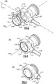
- an end fitting connector assembly 100 made in accordance with a first exemplary embodiment is defined by an end fitting 110, including a clevis or other similar component.
- the end fitting 110 is defined by a fitting body having a proximal end 111 and a distal end 113, in which a through opening 114 extends in a direction that is transverse to a center axis 115 of the end fitting 110 extending through the proximal and distal ends 111, 113.
- the end fitting 110 is fabricated from a structural material, such as stainless steel or an aluminum alloy though it should be noted that other suitable materials, such as a hard and durable plastic, can alternatively be used for purposes of manufacture of this component.
- the transverse through opening 114 is substantially circular and defined by a center axis 148, as well as a peripheral wall 118 forming an outer radial boundary of the through opening 114.
- the center axis 148 also defines an assembly axis for purposes of the end fitting 110 and all components mounted within the through opening 114.
- an annular groove 120 is disposed in approximately the center of the peripheral wall 118 between opposing opening ends 117, 119 of the through opening 114.
- the proximal end 111 of the end fitting 110 in accordance with this embodiment includes an engagement portion 127 that is configured to fixedly support one end of a cylindrical rod 126.
- the end fitting connector assembly 100 further includes a race 130 that is configured to be positioned within the transverse through opening 114 of the end fitting 110.
- the race 130 is a ring-like member having an outer or exterior surface 134 and an inner or interior surface 138 in which the outer surface 134 of the race 130 is configured to engage the peripheral wall 118 of the end fitting 110 in an elastically deformable manner.
- the race 130 is preferably made from a sufficiently flexible and durable plastic material, such as acetal although other elastically deformable materials can be utilized.
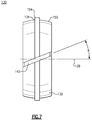
- a slit 142 is formed in the race 130, creating a split ring configuration. According to this specific embodiment and as more clearly shown in Figs.
- the slit 142 is formed by means of a scarf cut formed preferentially at an angle ⁇ relative to the center axis 139 of the race 130, which when assembled is coaxial with the axis 148 of the through opening 114.
- the angle ⁇ is about 15 degrees, although this parameter can be suitably varied.
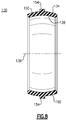
- the exterior surface 134 of the race 130 is largely defined by a spherical or substantially spherical configuration 150, as well as a raised circumferential ridge 154 disposed at approximately the center of the race 130 and substantially aligned along the axis 115 at the time of assembly of the end fitting 110.
- the exterior surface 134 of the race 130 can be defined using angled surfaces (not shown) disposed to either side of the annular ridge 154.
- a suitable range of angles can be about 5 to about 30 degrees.
- the elastically deformable race 130 is defined by an outer diameter (excluding that of the circumferential raised ridge 154) that is slightly smaller than that of the diameter of the center opening 114 of the end fitting 110.
- the diameter selected for use should be based on several factors including, but not limited to the desired amount of installation and retention force as well as load and wear capacity. In any case, however, this sizing should permit the elastically deformable race 130 to expand sufficiently to permit installation and removal of the ball mount 170. As shown in Fig.
- the scarf cut defining the slit 142 permits the elastically deformable race 130 to be installed into the transverse through opening 114 of the end fitting 110 by elastically deforming the race 130 and more specifically elastically curling the race 130 to a smaller diameter and then allowing expansion once the race 130 is in a predetermined position.
- the formed split ring configuration as well as the substantially spherical outer surface 134 permits the race 130 to be assembled and secured with the raised circumferential ridge 154 being positively engaged with the annular groove 120 of the end fitting 110, thereby fixing the race 130 into the predetermined position depicted in Fig. 10 .
- a ball mount 170 having a spherical outer surface 174 over at least a portion thereof can then be snap-fitted within the end fitting connector assembly 100 and more specifically provide positive retaining engagement between the substantially spherical inner surface 138 of the race 130 and the outer spherical surface 174 of the ball mount 170.
- the transverse through opening 114 of the end fitting 110 provides a container or receptacle for the elastically deformable race 130, supporting the race 130 and protecting it from damage, wherein a connective link is provided to the device that the herein described assembly 100 is attached.
- the end fitting 110 also limits how much the race 130 may open at the slit 142 such that, once the outer diameter of the race 130 contacts the inner diameter face of the transverse center opening 114, the race 130 must elastically expand at one or the other end in the race 130 (i.e., proximal to the ends 117, 119, Fig. 10 ) as the ball mount 170 enters or exits.
- the race 130 If the race 130 is not adequately restrained within the end fitting body 110, the race 130 would simply open at the slit 142 with relative ease and be rendered relatively ineffective in restraining the ball mount 170. In other words, the fitting body 110 restrains the race 130 such that it acts almost as though the slit 142 was not present and the smaller diameter opening on either side of the race 130 must effectively "snap" over the larger diameter of the ball mount 170.
- the elastically deformable race 130 which can be made according to this embodiment from a moldable durable plastic, forms a "socket" into which the ball mount 170 is installed and retained.
- the ball mount 170 provides a 360 degree range of motion about the center axis 148 of the transverse through opening 114 of the end fitting 110, the ball mount 170 providing a compressive force against the race 130 and engaging same, the race 130 being retained by the end fitting 110.
- a small amount of perpendicular motion may also be permitted (typically on the order of about 5 degrees) to allow for misalignment.
- the ball mount 170 may be part of a stud or alternatively can be part of a bracket or other assembly. The ball mount 170 may be permitted to rotate, but such rotation may not be necessary depending on the specific application or use of the assembly.
- the joint is created by snap fitting the assembled race 130 over the ball mount 170, or by snapping the ball mount 170 into the end fitting connector assembly 100.
- This assembly can be performed using hand force by a single person and without requiring the use of tools or persons in which one of the two end pieces of the assembly 100 is already held stationary or resting on a support or table (not shown).
- the end fitting 110 and the ball mount 170 engage one another along their aligned central axes. Separation of the created joint can be effected by pulling the ball mount 170 or the end fitting 110 apart in the opposite direction.
- the race 130 may be manufactured with a significantly wider ridge on its outer diameter that is configured to be engaged within a mating groove feature in the end fitting 110 in a snap fitting configuration.
- the latter type of retention is useful for insuring that disassembly will require a larger force than the force enabling the snap fit of the components.
- a camming action can be created such that the force required for dissasembly is extremely high, as compared to the assembly force, thereby effectively preventing the joint from being easily disassembled.
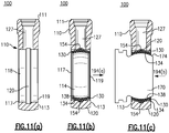
- FIGs. 11(a) - 12(b) One example of the foregoing design that includes a cammed annular groove 120 is shown in Figs. 11(a) - 12(b) .
- similar parts are labeled with the same reference numerals for the sake of clarity.
- Fig. 11(a) depicts an end fitting 110, in section, having a through opening 114 and peripheral wall 118 having the tapered annular groove 120.
- a suitable angle for the taper may be greater than or less than 45 degrees, with the groove 120 having a minimum width at the bottom of the groove 120, and a maximum width at the top of the groove 120.
- the end fitting 110 may be literally identical to that previously described in detail with regard to Figs. 2-5 , 9 and 10 .
- Fig. 11(b) illustrates the assembly of the elastically deformable (preferably plastic) race 130 to the end fitting 110 and more specifically to the through opening 114.
- the race 130 includes each of the previously described elements depicted in Figs. 6-8 and is literally identical thereto. More specifically, the race 130 includes an outer surface 134 and an inner surface 138, each of the foregoing surfaces according to this embodiment being defined as substantially spherical edges extending along the direction of the through opening 114 and configured for engagement with the peripheral wall 118 of the through opening 114.
- the elastically deformable race 130 has a slightly smaller outer diameter (with the exception of a raised circumferential ridge 154) than the diameter of the through opening 114 wherein a slit 142, Fig. 12(a) , enables the race 130 to be curled elastically.
- This dimensioning permits the raised circumferential ridge 154 on the outer surface 134 of the race 130 to be aligned with the angled surfaces of the annular groove 120 of the peripheral wall 118 of the end fitting 110, thereby placing the elastically deformable race 130 in a predetermined position.
- Fig. 11(c) illustrates the further attachment of a spherical ball mount 170 to the connector assembly 100 in which the inner surface 138 of the race 130 substantially conforms to the outer surface 174 of the spherical ball mount 170 and in which the ball mount 170 can be advantageously installed (or disassembled) in either axial direction 194(a) or 194(b) based on the symmetry of the components.
- Figs. 12(a) and 12(b) illustrate separate sectioned views of this assemblage as well as the connection of a rod end 126 within an engagement portion 127 of the end fitting 110.
- the angled surfaces of the annular groove 120 create a camming action.
- This action based on axial movement of the ball mount 170 in either the direction 194(a) or 194(b) increases the force required to disassemble the ball mount 170.
- the elastically deformable race 130 is thereby configured to move with the ball mount 170, which maintains the maximum engagement of the inner surface 138 of the race 130 with the outer spherical surface 174 of the ball mount 170.
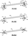
- a rate control is defined by a cylindrical section 180 having the movable rod end 126 at one end, which is securely mounted within the engagement portion 127.
- Attached to a fixed opposite end of the cylindrical section 180 is an end fitting 186, the latter component being substantially similar to the end fitting 110 other than being attached to a stationary portion of the cylindrical section 180.
- the elastically deformable race 130 is attached to the respective end fittings 110, 186 in the manner previously described wherein the race 130 is elastically curled and moved into the defined transverse through opening 114 with a raised circumferential ridge 154 of the race 130 being aligned and secured within a defined annular groove on a peripheral wall 118 of the through opening 114 of the end fitting 110.
- each of the assembled end fittings 110, 186 can then be snap fitted to respective spherical ball mounts 170, each of the latter components including a retainer plate 184 having attachment holes 188 for securing the ball mount 170 using fasteners (not shown) to respective structures (not shown) in order to complete the assembly.
- each of the ball mounts 170 are shown beneath the cylinder section 180.
- the ball mounts 170 could be positioned directly above the cylinder section 180 as shown, given the symmetrical relationships of the assembled race 130 and transverse through opening 114 of the herein described end fittings 110, 186.
- a ball having a spherical surface over at least a portion thereof is necessary for purposes of securement of the end fitting connector assembly described herein, the remaining features of the ball mount itself can be made according to a number of configurations.
- different mounting configurations for the ball itself can be utilized, as shown for example in Figs. 14(a) and 14(b) , in which an alternative ball mount 270 includes a spherical ball end 274, similar to those previously described, that is integral to an axial threaded portion 278 in lieu of a retaining plate 184, Fig. 13(a) , on either or both sides of the assembly.
- a ball mount 270 includes a spherical ball end 274, similar to those previously described, that is integral to an axial threaded portion 278 in lieu of a retaining plate 184, Fig. 13(a) , on either or both sides of the assembly.
- other suitable variations can be contemplated including stud, plate or other variations.
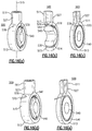
- the end fitting connector assembly 300 includes an end fitting 310 having a proximal end, a distal end and a through opening 314 that is transverse to an end fitting axis extending through the proximal end and the distal end, the through opening 314 being appropriately sized for receiving and retaining an elastically deformable race 320.
- a peripheral wall 318 of the through opening 314 includes a pair of recessed portions 330 defined at respective first and second ends 317, 319 of the through opening 314.
- the elastically deformable race 320 is a ring-like member preferably made from a flexible and durable plastic having a pair of opposing outwardly directed peripheral end portions 324 that are configured for engagement within the recessed portions 324 of the through opening 314 of the end fitting 310.
- a ball mount 340 (partially shown) is snap-fitted within the through opening 314, the ball mount 340 having a spherical outer surface 344 that engages the inner surface of the race 320 and elastically deforms same to create positive engagement.
- the inner surface of the elastically deformable race 320 substantially conforms to the outer spherical surface 344 of the ball mount 340 while the center portion of the outer surface of the race 320 is further caused to directly engage the peripheral wall 318 of the through opening 314 of the end fitting 310, thereby positively retaining the ball mount 340 to the end fitting connector assembly 300.
- movement of the ball mount 340 in the axial direction 348 causes a rearward peripheral end portion 330 of the race 320 to engage against a shoulder 336 of the peripheral wall 318 adjacent the recessed portion 330 of the through opening 314, preventing the elastically deformable race 320 from movement along with the ball mount 340 in the axial direction 350.
- a rearward peripheral end portion 330 of the race 320 engage against a shoulder 336 of the peripheral wall 318 adjacent the recessed portion 330 of the through opening 314, preventing the elastically deformable race 320 from movement along with the ball mount 340 in the axial direction 350.
- the spherical outer surface 344 of the ball mount 340 such engagement effectively prevents further movement of the race 320 to enable disassembly of the ball mount 340 from the end fitting connector assembly 300.
- axial movement of the ball mount 340 in the opposite direction would produce a similar effect.
- the end fitting connector assembly 500 includes an end fitting 510 having a distal end 511, a proximal end 513 and an end fitting axis 515 passing through the first and second ends 511, 513.
- a through opening 514 provided between the first and second ends 511, 513 of the end fitting 510 extends in a direction that is transverse to the end fitting axis 515 and is defined by a peripheral wall 518.
- the proximal end 513 of the end fitting 510 includes an engagement portion 527 that is configured to secure a rod end (not shown).
- the end fitting connector assembly 500 further includes a elastically deformable race 530 that is mounted or installed into the through opening 514 in which an exterior or outer surface of the race 530 engages the peripheral wall 518 and an interior or inner surface of the race 530 is configured and sized to engage the outer spherical surface 542 of a ball mount 540.
- each of the interior and exterior surfaces of the flexibly deformable race 530 are substantially spherical or at least angled.
- the exterior surface of the race 530 and the peripheral wall 518 of the end fitting 510 include aligned grooves 517, 534, respectivelyin which the grooves 534 of the end fitting 510 include angled or tapered wall surfaces, shown only in Fig. 16(b) , which upon attachment to the ball mount 540 combine to create a camming action that prevents or substantially restricts disassembly when the ball mount 540 is moved axially.
- An opening 578 is provided in the exterior surface of the end fitting 510 that extends through the end fitting 510 to the peripheral wall 518 and to the spacing between the grooves 517, 534.
- the opening 578 is sized to accommodate a release tool, such as an axial section of wire 570 or other suitably configured member that can be introduced through the opening 578 provided in the exterior surface of the end fitting 510 and directly into the spacing defined between the aligned grooves 517, 534.
- a release tool such as an axial section of wire 570 or other suitably configured member that can be introduced through the opening 578 provided in the exterior surface of the end fitting 510 and directly into the spacing defined between the aligned grooves 517, 534.
- the presence of the axial section of wire 570 creates an obstruction that prevents the camming action between the surfaces of the elastically deformable race 530 and the end fitting 510 and more easily permits disassembly of the ball mount 540 from the end fitting connector assembly 500.
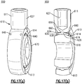
- FIGs. 17(a) and 17(b) depicts.
- the connector assembly 600 similarly includes an end fitting 610, such as a clevis or similar component, having a distal end 611, a proximal end 613 having an engagement portion 627, and a through opening 614 that extends in a direction that is transverse to an end fitting axis extending through the distal and proximal ends 611, 613.
- An elastically deformable race 630 is a ring-like member including an outer surface 634 that engages a peripheral wall 618 of the through opening 614 and an inner surface 638 that is configured and sized to engage the outer spherical surface 674 of a ball mount 670 in a snap fitting arrangement. Similar to the embodiment previously described with regard to Figs.
- each of the inner and outer surfaces 638, 634 of the race 630 are defined by a spherical configuration wherein the outer surface 634 of the race 630 includes an annular circumferential ridge 639 which is configured to engage a continuous groove 650 that is defined in the peripheral wall 618 when the ball mount 670 is snap fitted to the assembly 600.
- the foregoing feature insures that when assembled, the elastically deformable race 630 is disposed in a predetermined position.
- a pair of openings 640 are provided in the exterior surface of the end fitting 610 that extend into the assembly 600 and between the elastically deformable race 630 and the peripheral wall 618 of the end fitting 610 at spaced portions thereof.
- the openings 640 are spaced axially from one another on opposing sides of the groove 650 and annular ridge 639 that secures the race 630 to the end fitting 610.
- axial sections of locking wire(s) 660 are provided and inserted into each of the openings 640, the locking wires 660, Fig.
- the end fitting connector assembly 700 includes an end fitting 710 that is defined by a transverse through opening 714 formed in a distal end having a peripheral wall 718 that is sized and configured to accommodate an elastically deformable race 730.
- the elastically deformable race 730 is defined by a ring-like member having an outer surface 734 and an inner surface 738 in which the outer surface 734 further includes a circumferential raised ridge 740 at about the center thereof configured for engaging a groove 750 formed in the peripheral wall 718 of the end fitting 710.
- each of the circumferential raised ridge 740 of the race 730 and the groove 750 of the end fitting 710 further include an additional annular groove or notch 744, 748, respectively, each of the grooves 744, 748 being aligned with one another upon assembly.
- a wire clip 780 defined by a ring-like configuration is initially provided within the annular groove 748 defined in the peripheral wall 718 of the end fitting 710.
- the wire clip 780 extends along substantially the entire circumference of the groove 748 and has respective ends 784 that extend to a projecting portion of the end fitting 710 and more specifically a through opening 788 of the end fitting 710 that extends transversely to the axis of the through opening 714.
- a ball mount 770 includes an outer spherical surface 774 that is engaged by the inner surface 738 of the race 730 in a snap-fitting engagement.
- the wire clip 780 is initially radially biased such that the wire clip 780 is entirely positioned within the defined groove 748 of the end fitting 710, as shown most clearly shown in Fig. 18(b) .
- the inner surface 738 of the elastically deformable race 730 is engaged with the outer surface 774 of the spherical ball mount 770 and the circumferential raised ridge 740 of the race 730 is engaged within the groove 750 of the peripheral wall 718 of the end fitting 710.
- the race 730 is constrained into engagement with the end fitting 710 and the ball mount 770 in a manner that prevents disassembly without concerted effort or as in this embodiment, a tool.
- the outer circumferential ridge 740 of the race 730 is retained within the groove 750 defined by the end fitting 710 and the angled end walls of the groove 750 prevent the race 730 from movement in the direction along the axis 778 of the through opening 714 and correspondingly prevent movement of the ball mount 770 against the constrained race 730.
- a peripheral portion of the wire clip 780 is at least partially released from the groove 748 of the end fitting 710 and becomes at least partially disposed within the aligned groove 744 of the race 730.
- This latter position creates locking engagement between the race 730 and the end fitting 710, preventing relative movement.
- the outer spherical surface 774 of the ball mount 770 can easily move against the inner surface 738 of the race 730.
- the ball mount 770 can be easily disassembled.
- the entering tool upon engaging the extending end of the wire clip 780 can be rotated in the direction 794 that facilitates this disassembly in either direction 797, 799 of the through opening 714.
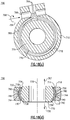
- FIGs. 19 (a) and 19 (b) Yet another alternate embodiment of an end fitting connector assembly 800 is depicted in Figs. 19 (a) and 19 (b) .
- This assembly 800 like the preceding, includes an end fitting 810 defined by a distal end and a proximal end, the distal end being further defined by a transverse through opening 814 having a peripheral wall 818.
- An elastically deformable race 830 is further provided having an outer surface 834 and an inner surface 838 in which the inner surface 838 is defined by a spherical or substantially spherical configuration that is configured for engaging the outer spherical surface 874 of a ball mount 870.
- a circumferential raised ridge 840 formed on the outer surface 834 of the race 830 is compressively engaged with the peripheral wall 818 of the end fitting 810 upon assembly, the latter wall 818 including a profile having a plurality of stepped surfaces 845, 847 spaced from a groove or notch 850 disposed at about the center of the axial span of the peripheral wall 818.
- the circumferential ridge 840 of the race 830 is further defined by a notch or groove 842 at about the center of the ridge 840, each of the grooves 842, 850 being substantially the same width dimension.
- the first pair of stepped surfaces 845 of the peripheral wall 818 of the through opening 814 define a first recessed portion 888 that is sized to accommodate the raised circumferential ridge 840 and permit limited movement of the race 830 in either axial direction 890.
- the second set of stepped surfaces 847 according to this embodiment extend radially inward and define an additional recessed portion 889.
- a wire clip 880 is initially disposed within the end fitting 810 and more specifically within the groove 850 of the end fitting 810, the wire clip 880 having a diameter that enables same to be fully and solely retained within the groove 850 initially.
- the elastically deformable race 830 in the initial assembled condition can translate slightly along in either axial direction relative to the through opening 814 of the connector assembly 800 within the recessed portion 888, but is prevented or at least constrained from further movement based on this geometry. Based upon this constraint, only limited movement is permitted between the ball mount 870 and the race 830 and disassembly is made difficult without the application of a greater amount of force than required for purposes of assembly.
- the wire clip 880 When the wire clip 880 is acted upon, for example in the manner previously illustrated according to Figs. 18(c) and 18(d) using a tool (not shown), and as shown in Fig. 19(b) at least a peripheral portion of the wire clip 880 is caused to move radially inward, away from the confines of the groove 850 of the peripheral wall 818 of the end fitting 810 and at least partially into the groove 842 formed on the circumferential raised ridge 840 of the race 830. In this latter position, the race 830 becomes effectively locked meaning that the race 830 is prevented from any movement independent of the end fitting 810 in the direction 890. Therefore, the ball mount 870 is not constrained by the race 830 and can be easily disassembled in either direction 890.
- each of the elastically deformable races described in the prior embodiments can be formed from a plastic material in which fabrication by molding can facilitate manufacture, including the salient features such as the inner and outer surfaces as well as the circumferential outer edge and the grooves.
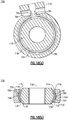
- another end fitting connector assembly 900 can be provided that includes an end fitting 910 defined by a transverse through opening 914 and a peripheral wall 918 and an elastically deformable race 930.
- the race 930 is defined by a ring-like section made from a metal, such as bronze or steel, having a through opening that is aligned with the through opening 914 of the end fitting 910, when assembled.
- the peripheral wall 918 of the end fitting 910 includes an annular groove 950 disposed at about the center of the axial dimension of the through opening 914.
- the groove 950 according to this specific embodiment is defined by a substantially concave configuration.
- the race 930 is defined by a thin ring-like structure including an outer surface 934 and an inner surface 938, as well as opposing first and second ends 943, 945.
- Each of the first and second ends 943, 945, including the outer and inner surfaces 934, 938, are mirror images of one another and are commonly defined by a plurality of spaced castellations 935 equally spaced and arranged circumferentially.
- Each castellation 935 according to this embodiment is a cantilevered spring having an outer end 939 that is reflexed radially inward relative to an inner end 941.
- Each of the inner ends 941 of the castellations 935 on each side 943, 945 of the race 930 terminate commonly to a center concave portion 954 extending radially outward and initially retained within the groove 950, when assembled, as shown in Fig. 20(a) .
- the race 930 is shown as assembled and in which the radially protruding center portion 954 of the race 930 is engaged with the groove 950 formed in the peripheral wall 918 of the transverse through opening 914 of the end fitting 910 in the direction 990. It should be noted that assembly can proceed from either axial end of the herein described assembly 900. As the ball mount 970 is engaged at one of the ends 943 of the assembled race 930, the outer spherical surface 974 of the ball mount 970 directly engages the outer ends 939 of the spring-like castellations 935 causing the outer ends 939 on that side 943 of the race 930 to deflect radially outward toward the peripheral wall 918.
- the spherical contour of the outer surface 974 causes the outer ends 939 of the castellations 935 to additionally deflect elastically and further causing the race 930 to pivot about the concave projecting portion 954 within the groove 950.
- This pivoting action enables the ball mount 970 to be fully assembled into the position shown in Fig. 20(b) .
- the race 930 is prevented from axial movement by the peripheral wall 918 of the end fitting 910 and more specifically the engagement of the protruding portion 954 of the race 930 within the groove 950 of the peripheral wall 918 of the through opening 914 and the spherical outer wall 974 of the ball mount 970. Due to the tapered geometry of the castellations 935 and the biasing forces provided, disassembly is thereby prevented without use of a tool or at least from occurring easily using a greater applied force than that applied during assembly.
Description
- This application is generally directed to the field of component manufacture and more specifically directed to an end fitting connector assembly that permits one-handed assembly for efficiently and reliably enabling use in various structural applications.
- So called "quick connect" end fitting connectors are known for use in various assemblies, such as linear or hydraulic rate control or actuator assemblies. In a typical configuration, an axially movable rod end of a rate control or an actuator component is engaged with an end fitting, such as a clevis, to provide engagement with a spherical ball mount that is attached to a mated structure.
- By way of example and referring to
Fig. 1 , there is shown a prior art endfitting connector assembly 10 that is used to interconnect an axiallymovable rod end 14 with a structure, such as a stowage bin of a stowage compartment typically found in commercial aircraft, the latter including aretainer plate 18. Theretainer plate 18 includes a plurality ofattachment holes 22, which are spaced and configured to receive fasteners (not shown) for fixedly securing same to a structure (not shown). Disposed at themovable rod end 14 is aclevis lug 28, which is defined by a substantially T-shaped body. Theclevis lug 28 is configured for engagement with a corresponding T-shaped receiving slot 32 of aclevis mount 40 that is pivotally secured to theretainer plate 18. In operation, theclevis lug 28 is mated to theclevis mount 40, and more specifically the T-shaped receivingslot 32, wherein theclevis lug 28 includes aspring retention clip 44 at its distal end that creates positive engagement upon attachment to theclevis mount 40. - When properly engaged, this end
fitting connector assembly 10 does not permit disassembly without the aid of a release tool (not shown). According to this version, the release tool can be introduced into the T-shaped receiving slot 32 and more specifically into direct engagement against thespring retention clip 44 to compress same and enable theclevis lug 28 to be removed from the T-shaped receiving slot 32 of theclevis mount 40. - There is a general need in the field to simplify the design of end fitting connectors, such as those shown in
Fig. 1 , but without sacrificing reliability. There is a similar need to provide an end fitting that enables one handed assembly, but prevents disassembly preferably without the use of a tool or other release feature.US 4 260 275 A ,US 3 753 584 A andGB 1 423 032 A - Therefore and according to one aspect, there is provided an end fitting connector assembly according to claim 1. The end fitting connector comprises an end fitting having a first end, a second end and a through opening transversely disposed in relation to an axis passing through the first and second ends, the through opening being defined by a peripheral wall. An elastically deformable race is fitted within the circular opening of the end fitting, the race having an outer surface that engages the peripheral wall and an inner surface that is configured to engage a spherical ball mount.
- In at least one version, the end fitting connector assembly further includes at least one feature that maintains the elastically deformable race in a predetermined position relative to the transverse through opening of the end fitting, such that the spherical ball mount cannot easily be removed following assembly.
- In one version, one of the race or the peripheral wall includes a raised circumferential ridge and the other of the race and the peripheral wall includes an annular groove sized for receiving the raised circumferential ridge and defining the features for retaining the race in the predetermined position.
- The elastically deformable race can be defined by a ring-like configuration having a slit along the circumference thereof that creates a split ring configuration. The elastically deformable race or the annular groove of the peripheral wall of the end fitting can further include at least one raised circumferential ridge, which is configured and sized to engage an annular groove formed in the other of the peripheral wall of the end fitting and the race. In one version, at least one of the annular groove and the raised circumferential ridge can be defined by square edges, while in another version the annular groove can be defined by tapered walls that are aligned with the raised circumferential ridge in order to create an additional compressive force and/or a "locking" feature that increases the force required for assembly or disassembly and in at least some instances requiring a tool or other release feature.
- In another version, the outer surface of the elastically deformable race and the peripheral wall of the through opening of the end fitting can include aligned grooves though which a locking element can be transversely disposed to effect disassembly by effectively locking the race with the end fitting and preventing the race to translate along with the ball mount. Based on the spherical or angled surfaces of these components, disassembly can be effected. The locking element can be integrally disposed within the end fitting or can be provided separately in which the end fitting is configured for accepting the locking element and can be engaged for release by a tool.
- Though the race can be made from plastic, it may also be manufactured from other suitable materials, including metal, to serve the intended functionality of being elastically deformable as discussed herein. For example and according to at least one version, an elastically deformable race can be defined by a metal body defined by a radially protruding center portion and a pair of opposed axial ends. Each of the axial ends include a series of spaced castellations that form cantilevered springs about the periphery of the end fitting when the race is attached thereto. Via the cantilevered springs, a ball mount can be assembled and wherein the springs form a resistive force to prevent disassembly.
- In yet another version, the peripheral wall of the end fitting can include a pair of recessed portions that are aligned with outwardly extending end portions of the race and configured to increase the amount of force that is required for disassembly.
- According to another aspect, there is provided a method for enabling one-handed operation of an end fitting connector assembly according to
claim 8. The method comprises:
providing an end fitting having a first end, an opposing second end and a through opening between the first and second ends that is transverse to an axis extending between the first and second ends, the through opening further defining a peripheral wall; and
providing an elastically deformable race that is sized to be engaged within the through opening of the end fitting, the race having an exterior spherical surface in contact with the peripheral wall and an inner surface configured to directly and snapfittingly engage a spherical ball mount. - In at least one embodiment, at least one of the elastically deformable race and the peripheral wall of the end fitting are provided with at least one engagement feature for retaining the race in a predetermined position. In one such version, the engagement feature includes a raised circumferential ridge of one of the race and peripheral wall that engages an annular groove of the other.
- The annular groove can include tapered or angled surfaces to provide a locking effect.
- In yet another version, the outer surface of the elastically deformable race and the peripheral wall of the through opening of the end fitting can include aligned grooves though which a locking element can be transversely disposed to effect disassembly by effectively locking the race with the end fitting and preventing the race to translate along with the ball mount. Based on the spherical or angled surfaces of these components, disassembly can be effected. The locking element can be integrally disposed within the end fitting or can be provided separately in which the end fitting is configured for accepting the locking element and can be engaged for release by a tool.
- The elastically deformable race can be made from plastic and can further be defined by a split-ring configuration. In one such version, a slit is provided in the race to enable elastic deformation. This slit can be defined, for example, by a scarf cut. In at least one version, the scarf cut can be angled.
- According to yet another aspect, there is provided a rate control or an actuator comprising a rod member having at least one end, and an end fitting connector assembly attached to the at least one end of the rod member. The end fitting connector assembly comprises an end fitting having a first end, a second end and a through opening extending in a direction that is transverse to an axis passing through the first and second ends, the through opening defining a peripheral wall; and an elastically deformable race disposed within the through opening of the end fitting and having a substantially spherical exterior surface engaged with the peripheral wall, at least one of the race or the end fitting having a feature that retains the race in a predetermined position, the race having a substantially spherical interior surface configured for positive engagement with a spherical ball mount.
- In one version, one of the race or the peripheral wall includes a raised circumferential ridge and the other of the race and the peripheral wall includes an annular groove sized for receiving the raised circumferential ridge and defining the features for retaining the race in the predetermined position.
- The elastically deformable race can be defined by a ring-like configuration having a slit along the circumference thereof that creates a split ring configuration. The elastically deformable race or the annular groove of the peripheral wall of the end fitting can further include at least one raised circumferential ridge, which is configured and sized to engage an annular groove formed in the other of the peripheral wall of the end fitting and the race. In one version, at least one of the annular groove and the raised circumferential ridge can be defined by square edges, while in another version the annular groove can be defined by tapered walls that are aligned with the raised circumferential ridge in order to create an additional compressive force and/or a "locking" feature that increases the force required for assembly or disassembly and in at least some instances requiring a tool or other release feature.
- In another version, the outer surface of the elastically deformable race and the peripheral wall of the through opening of the end fitting can include aligned grooves though which a locking element can be transversely disposed to effect disassembly by effectively locking the race with the end fitting and preventing the race to translate along with the ball mount. Based on the spherical or angled surfaces of these components, disassembly can be effected. The locking element can be integrally disposed within the end fitting or can be provided separately in which the end fitting is configured for accepting the locking element and can be engaged for release by a tool.
- One advantage realized by the foregoing assembly design is that of simplicity in that fewer parts are utilized than previously known end fitting assemblies having similar functionalities. As a result, the herein described end fitting connector assembly is both simpler and cheaper to manufacture/fabricate.
- Another advantage provided by the herein described assembly is ease in use, as compared with previously known end fitting assemblies. Simple one-handed operation is assured during assembly of the ball mount to the joint. In at least one version, disassembly can be readily conducted. According to another version, the force required to disassemble the ball from the assembly can be made considerably higher than the force required to assemble for example, requiring a tool or other release feature to effect disassembly.
- Yet another advantage is that the herein described end fitting assembly is symmetrical such that the formed joint can be made and/or unmade from either side or direction of the end fitting.
- Still another advantage is that of improved reliability since relatively fragile components, such as the herein described elastically deformable race, are protected within the end fitting, the latter acting as a container or receptacle.
- Another advantage is that at least one of the annular groove and the raised circumferential ridge is defined by opposing parallel edges. A further advantage is that alternatively or additionally at least one of the annular groove and the raised circumferential ridge is defined by tapered edges. The edges can preferably be tapered by about 45 degrees.
- According to another aspect, when the end fitting connector assembly further comprises a tool or release feature which is sized for insertion into a space defined between the aligned grooves, it is advantageous if the tool comprises a section of wire.
- Yet another advantage is that when the slit is defined by a scarf cut, the angle of the scarf cut is at least 15 degrees relative to a center axis of the race.
- In one version, in which the end fitting connector assembly comprises a release feature, it is advantageous if the release feature is a substantially circular wire clip initially biased into the groove of the end fitting.
- The exterior surface of the race can be defined by at least one angled surface.
- Another advantage is that when one of the end fitting and the race includes a raised circumferential ridge that engages an annular groove defined in the other of the end fitting and the race, the at least one of the annular groove and raised circumferential ridge include tapered edges. Alternatively or additionally, at least one of the annular groove and raised circumferential ridge is defined by substantially parallel edges.
- Furthermore, it is preferred if the method further includes the step of defining the race with a slit to enable a split ring configuration. The slit can be defined by a scarf cut.
- According to another aspect, a rate control or actuator according to claim 12 is provided. This rate control or actuator comprises a rod member having at least one end; and an end fitting connector assembly attached to the at least one end of the rod member, the end fitting connector assembly comprising: an end fitting having a first end, a second end and a through opening extending in a direction that is transverse to an axis passing through the first and second ends, the through opening defining a peripheral wall; and an elastically deformable race disposed within the through opening of the end fitting and having a substantially spherical exterior surface engaged with the peripheral wall, at least one of the race or the end fitting having a feature that retains the race in a predetermined position, the race having a substantially spherical interior surface configured for positive engagement with a spherical ball mount.
- According to a preferred modification of the rate control or actuator, the race and the peripheral wall of the end fitting each include corresponding engagement features for retaining the race in the predetermined position. Furthermore, one of the race and the peripheral wall includes an annular groove and the other of the race and the peripheral wall includes a raised circumferential ridge sized for engaging the peripheral groove. It is preferred that at least one of the annular groove and the raised circumferential ridge include angled walls to produce a camming effect when engaged by movement of the spherical ball mount.
- Furthermore, it is preferred that each of the peripheral wall of the end fitting and the exterior surface of the race include grooves aligned with one another, the grooves extending at least over an annular portion, and further comprising at least one of a tool or release feature which is sized for insertion into a space defined between the aligned grooves. Preferably, the release feature is initially disposed within only the groove of the end fitting and in which a tool is configured to engage the release feature in order to move the release feature at least partially into the groove of the race, thereby locking the race relative to the end fitting and enabling disassembly of the ball mount.
- Another advantage is, if the race includes a slit, creating a split ring. It is preferred that the slit is an angled scarf cut.
- Furthermore, it is preferred that the peripheral wall of the end fitting includes a pair of spaced recessed portions and the race includes a pair of inwardly directed end portions for engaging the recessed portions.
- According to a preferred modification of the rate control or actuator, the elastically deformable race is made from metal and includes an intermediate radially protruding portion and opposing axial ends, each of the axial ends having a plurality of peripherally disposed castellations, each of the castellations being defined by cantilevered springs wherein the protruding portion engages a groove of the end fitting and the castellations prevent disassembly of the ball mount.
- Still further, yet another advantage realized is that no special tooling is required to assemble the race to the end fitting.
- The herein described assembly is also lighter than prior known connector assemblies.
- Furthermore, the herein described concepts can further be applied to literally any form of connection including cylinder ends, stays, struts and the like for which a quick connect fitting is desired that provides retention about a ball or similar mount, while providing some degree of permissible misalignment.
- These and other features and advantages will be readily apparent from the following Detailed Description, which should be read in conjunction with the accompanying drawings.
-
-
Fig. 1 is a partial perspective view of an end fitting connector assembly in accordance with the prior art; -
Fig. 2 is an exploded assembly view of an end fitting connector assembly made in accordance with an exemplary embodiment; -
Fig. 3 is a partially exploded assembly view of the end fitting connector assembly ofFig. 2 , depicting the assembly of a race relative to an end fitting; -
Fig. 4 is a partially exploded view of the end fitting assembly ofFigs. 2 and3 , following the assembly of the race to the end fitting; -
Fig. 5 is an assembled view of the end fitting connector assembly ofFigs. 2-4 ; -
Fig. 6 is a top plan view of a elastically deformable race for the end fitting connector assembly and in accordance with an exemplary embodiment; -
Fig. 7 is a side facing view of the elastically deformable race ofFig. 6 ; -
Fig. 8 is a side sectioned view of the elastically deformable race ofFigs. 6 and7 , taken through section lines 8-8 ofFig. 6 ; -
Fig. 9 is a top view of the end fitting connector assembly ofFig. 2 ; -
Fig. 10 is a sectioned view of the end fitting connector assembly ofFig. 5 , as taken through section lines 9 - 9 ofFig. 9 ; -
Fig. 11(a) is a sectioned view of an end fitting prior to assembly of a race in accordance with another exemplary embodiment; -
Fig. 11(b) is the sectioned view of the end fitting ofFig. 11(a) , with an assembled race; -
Fig. 11(c) is the sectioned view of the end fitting ofFig. 11(b) as assembled to a spherical ball mount; -
Fig. 12(a) is a perspective sectioned view of the end fitting connector assembly as attached to a spherical ball mount; -
Fig. 12(b) is a perspective view of the end fitting connector assembly ofFig. 12(a) , as sectioned 90 degrees relative toFig. 12(a) ; -
Fig. 13(a) is a perspective partially exploded view of end fitting connector assemblies relative to a structural application; -
Fig. 13(b) is the perspective view of the end fitting connector assemblies, as assembled, and prior to attachment to various structural members; -
Fig. 13(c) is the perspective view of the end fitting connector assembly ofFigs. 13(a) and 13(b) , as assembled to the ball mounts of the various structural members; -
Fig. 14(a) is the end fitting connector assembly ofFig. 13(b) prior to engagement with an alternative ball mount; -
Fig. 14(b) is the end fitting connector assembly ofFig. 14(a) , as attached to the ball mount; -
Fig. 15 is a partial sectioned view of an end fitting connector assembly that is made in accordance with another exemplary embodiment; -
Fig. 16(a) is a perspective view of an end fitting connector assembly in accordance with another exemplary embodiment; -
Fig. 16(b) is a sectioned view of the end fitting connector assembly ofFig. 16(a) ; -
Fig. 16(c) is another sectioned view of the end fitting connector assembly ofFigs. 16(a) and 16(b) ; -
Fig. 16(d) is the perspective view of the end fitting connector assembly ofFig. 16(a) , including a feature that enables release of a ball mount from the end fitting; -
Fig. 16(e) is the sectioned view of the end fitting connector assembly ofFig. 16(c) including the ball mount release feature; -
Fig. 17(a) is a side perspective view of an end fitting connector assembly in accordance with yet another exemplary embodiment; -
Fig. 17(b) is a sectioned view of the end fitting connector assembly ofFig. 17(a) ; -
Fig. 18(a) is a sectioned view of an end fitting connector assembly in accordance with another exemplary embodiment; -
Fig. 18(b) is a sectioned view about lines 18-18 of the connector assembly ofFig. 18(a) , showing the assembly in a locked condition; -
Fig. 18(c) is the sectioned view of the end fitting connector assembly ofFig. 18(a) in which the end fitting connector assembly is in an unlocked condition; -
Fig. 18(d) is the sectioned view about lines 18-18 of the connector assembly ofFig. 18(c) ; -
Fig. 19(a) is a partial sectioned view of an end fitting connector assembly in accordance with yet another exemplary embodiment and in which the connector assembly is in a locked condition; -
Fig. 19(b) is the partial sectioned view of the end fitting connector assembly ofFig. 19(a) with the connector assembly in an unlocked condition; -
Fig. 20(a) is a partial sectioned and partially assembled view of an end fitting connector assembly in accordance with yet another exemplary embodiment; -
Fig. 20(b) is the partial sectioned view of the end fitting connector assembly ofFig. 20(a) as assembled to a ball mount; and -
Fig. 20(c) is a side perspective view of the end fitting connector assembly ofFigs. 20(a) and 20(b) . - The following refers to certain and exemplary embodiments of a one-hand operable end fitting connector assembly intended for use in various applications, including but not limited to actuators, mounts rate controls, shocks, struts, stays, cable assemblies and the like and particularly those instances in which in plane rotation about the transverse hole axis in the end fitting assembly is required and where some degree of misalignment between attachment points/planes may be anticipated, such as, for example, an instance in which a spherical ball joint is desirable. For example and according to one specific version, the end fitting connector assembly can be used in conjunction with a rate controlling actuator for an overhead stowage bin used in commercial aircraft. It will be readily apparent, however, that other suitable uses or applications for the herein described assembly can be easily contemplated by those persons of adequate skill. In addition and throughout this discussion, several terms are frequently used in order to provide a suitable frame of reference in regard to the accompanying drawings. These terms, which include "lateral", "peripheral", "inner", "outer", "above", "interior", "exterior", "below", "distal" and "proximal", among others, are not intended to be limiting of the inventive concepts that are discussed and claimed herein, except in those instances in which such intent is specifically and clearly indicated.
- This brief description is intended only to provide a brief overview of subject matter disclosed herein according to one or more illustrative embodiments, and does not serve as a guide to interpreting the claims or to define or limit scope, which is defined only by the appended claims. This brief description is provided to introduce an illustrative selection of concepts in a simplified form that are further described below in the Detailed Description. This brief description is not intended to identify key features or essential features of the claimed subject matter, nor is it intended to be used as an aid in determining the scope of the claimed subject matter. The claimed subject matter is not limited to implementations that solve any or all disadvantages noted in the Background.
- As used in this specification and the appended claims, the singular forms "a", "an" and "the" are intended to further include plural referents unless the context clearly dictates otherwise.
- The term "about" as used in connection with a numerical value throughout the description and the claims denotes an interval of accuracy, familiar and acceptable to a person skilled in the art. The interval governing this term is preferably ± 20 %.
- Referring to
Figs. 2 - 5 , an endfitting connector assembly 100 made in accordance with a first exemplary embodiment is defined by an end fitting 110, including a clevis or other similar component. The end fitting 110 is defined by a fitting body having aproximal end 111 and adistal end 113, in which a throughopening 114 extends in a direction that is transverse to acenter axis 115 of the end fitting 110 extending through the proximal anddistal ends opening 114, according to this specific embodiment, is substantially circular and defined by acenter axis 148, as well as aperipheral wall 118 forming an outer radial boundary of the throughopening 114. As discussed herein, thecenter axis 148 also defines an assembly axis for purposes of the end fitting 110 and all components mounted within the throughopening 114. According to this exemplary embodiment, anannular groove 120 is disposed in approximately the center of theperipheral wall 118 between opposing opening ends 117, 119 of the throughopening 114. Theproximal end 111 of the end fitting 110 in accordance with this embodiment includes anengagement portion 127 that is configured to fixedly support one end of acylindrical rod 126. - The end
fitting connector assembly 100 further includes arace 130 that is configured to be positioned within the transverse throughopening 114 of the end fitting 110. According to this specific embodiment and as shown more clearly inFigs. 6-8 , therace 130 is a ring-like member having an outer orexterior surface 134 and an inner orinterior surface 138 in which theouter surface 134 of therace 130 is configured to engage theperipheral wall 118 of the end fitting 110 in an elastically deformable manner. According to this embodiment, therace 130 is preferably made from a sufficiently flexible and durable plastic material, such as acetal although other elastically deformable materials can be utilized. Aslit 142 is formed in therace 130, creating a split ring configuration. According to this specific embodiment and as more clearly shown inFigs. 7 and8 , theslit 142 is formed by means of a scarf cut formed preferentially at an angle α relative to thecenter axis 139 of therace 130, which when assembled is coaxial with theaxis 148 of the throughopening 114. According to this embodiment, the angle α is about 15 degrees, although this parameter can be suitably varied. Theexterior surface 134 of therace 130 is largely defined by a spherical or substantiallyspherical configuration 150, as well as a raisedcircumferential ridge 154 disposed at approximately the center of therace 130 and substantially aligned along theaxis 115 at the time of assembly of the end fitting 110. Alternatively and in lieu of being spherical, theexterior surface 134 of therace 130 can be defined using angled surfaces (not shown) disposed to either side of theannular ridge 154. Typically, a suitable range of angles can be about 5 to about 30 degrees. - According to this specific embodiment, the elastically
deformable race 130 is defined by an outer diameter (excluding that of the circumferential raised ridge 154) that is slightly smaller than that of the diameter of the center opening 114 of the end fitting 110. The diameter selected for use should be based on several factors including, but not limited to the desired amount of installation and retention force as well as load and wear capacity. In any case, however, this sizing should permit the elasticallydeformable race 130 to expand sufficiently to permit installation and removal of theball mount 170. As shown inFig. 3 , the scarf cut defining theslit 142 permits the elasticallydeformable race 130 to be installed into the transverse throughopening 114 of the end fitting 110 by elastically deforming therace 130 and more specifically elastically curling therace 130 to a smaller diameter and then allowing expansion once therace 130 is in a predetermined position. According to this embodiment, the formed split ring configuration as well as the substantially sphericalouter surface 134 permits therace 130 to be assembled and secured with the raisedcircumferential ridge 154 being positively engaged with theannular groove 120 of the end fitting 110, thereby fixing therace 130 into the predetermined position depicted inFig. 10 . - Referring to
Figs. 3-5 and10 , aball mount 170 having a sphericalouter surface 174 over at least a portion thereof can then be snap-fitted within the end fittingconnector assembly 100 and more specifically provide positive retaining engagement between the substantially sphericalinner surface 138 of therace 130 and the outerspherical surface 174 of theball mount 170. - When assembled and according to
Figs. 9 and 10 , the transverse throughopening 114 of the end fitting 110 provides a container or receptacle for the elasticallydeformable race 130, supporting therace 130 and protecting it from damage, wherein a connective link is provided to the device that the herein describedassembly 100 is attached. The end fitting 110 also limits how much therace 130 may open at theslit 142 such that, once the outer diameter of therace 130 contacts the inner diameter face of thetransverse center opening 114, therace 130 must elastically expand at one or the other end in the race 130 (i.e., proximal to theends Fig. 10 ) as theball mount 170 enters or exits. If therace 130 is not adequately restrained within the endfitting body 110, therace 130 would simply open at theslit 142 with relative ease and be rendered relatively ineffective in restraining theball mount 170. In other words, thefitting body 110 restrains therace 130 such that it acts almost as though theslit 142 was not present and the smaller diameter opening on either side of therace 130 must effectively "snap" over the larger diameter of theball mount 170. - As noted and though the end fitting 110 resembles a clevis, it may take other suitable forms. The elastically
deformable race 130, which can be made according to this embodiment from a moldable durable plastic, forms a "socket" into which theball mount 170 is installed and retained. When attached, theball mount 170 provides a 360 degree range of motion about thecenter axis 148 of the transverse throughopening 114 of the end fitting 110, theball mount 170 providing a compressive force against therace 130 and engaging same, therace 130 being retained by the end fitting 110. In addition, a small amount of perpendicular motion may also be permitted (typically on the order of about 5 degrees) to allow for misalignment. The ball mount 170 may be part of a stud or alternatively can be part of a bracket or other assembly. The ball mount 170 may be permitted to rotate, but such rotation may not be necessary depending on the specific application or use of the assembly. - In operation and as shown in
Figs. 2-5 ,9 and 10 , the joint is created by snap fitting the assembledrace 130 over theball mount 170, or by snapping theball mount 170 into the end fittingconnector assembly 100. This assembly can be performed using hand force by a single person and without requiring the use of tools or persons in which one of the two end pieces of theassembly 100 is already held stationary or resting on a support or table (not shown). The end fitting 110 and theball mount 170 engage one another along their aligned central axes. Separation of the created joint can be effected by pulling theball mount 170 or the end fitting 110 apart in the opposite direction. - In lieu of the raised
circumferential ridge 154, therace 130 may be manufactured with a significantly wider ridge on its outer diameter that is configured to be engaged within a mating groove feature in the end fitting 110 in a snap fitting configuration. The latter type of retention is useful for insuring that disassembly will require a larger force than the force enabling the snap fit of the components. - Moreover and by profiling the faces of the
annular groove 120 of the end fitting 110, a camming action can be created such that the force required for dissasembly is extremely high, as compared to the assembly force, thereby effectively preventing the joint from being easily disassembled.. - One example of the foregoing design that includes a cammed
annular groove 120 is shown inFigs. 11(a) - 12(b) . For purposes of this discussion, similar parts are labeled with the same reference numerals for the sake of clarity. -
Fig. 11(a) depicts an end fitting 110, in section, having a throughopening 114 andperipheral wall 118 having the taperedannular groove 120. Depending on the desired retention force, a suitable angle for the taper may be greater than or less than 45 degrees, with thegroove 120 having a minimum width at the bottom of thegroove 120, and a maximum width at the top of thegroove 120. Other than the taper in thegroove 120, the end fitting 110 may be literally identical to that previously described in detail with regard toFigs. 2-5 ,9 and 10 . -
Fig. 11(b) illustrates the assembly of the elastically deformable (preferably plastic)race 130 to the end fitting 110 and more specifically to the throughopening 114. As noted previously and for purposes of this discussion, therace 130 includes each of the previously described elements depicted inFigs. 6-8 and is literally identical thereto. More specifically, therace 130 includes anouter surface 134 and aninner surface 138, each of the foregoing surfaces according to this embodiment being defined as substantially spherical edges extending along the direction of the throughopening 114 and configured for engagement with theperipheral wall 118 of the throughopening 114. As in the preceding, the elasticallydeformable race 130 has a slightly smaller outer diameter (with the exception of a raised circumferential ridge 154) than the diameter of the throughopening 114 wherein aslit 142,Fig. 12(a) , enables therace 130 to be curled elastically. This dimensioning permits the raisedcircumferential ridge 154 on theouter surface 134 of therace 130 to be aligned with the angled surfaces of theannular groove 120 of theperipheral wall 118 of the end fitting 110, thereby placing the elasticallydeformable race 130 in a predetermined position. -
Fig. 11(c) illustrates the further attachment of aspherical ball mount 170 to theconnector assembly 100 in which theinner surface 138 of therace 130 substantially conforms to theouter surface 174 of thespherical ball mount 170 and in which theball mount 170 can be advantageously installed (or disassembled) in either axial direction 194(a) or 194(b) based on the symmetry of the components.Figs. 12(a) and 12(b) illustrate separate sectioned views of this assemblage as well as the connection of arod end 126 within anengagement portion 127 of the end fitting 110. - In operation and once installed, the angled surfaces of the
annular groove 120 create a camming action. This action based on axial movement of theball mount 170 in either the direction 194(a) or 194(b) increases the force required to disassemble theball mount 170. More specifically, the elasticallydeformable race 130 is thereby configured to move with theball mount 170, which maintains the maximum engagement of theinner surface 138 of therace 130 with the outerspherical surface 174 of theball mount 170. - Referring to
Figs. 13(a) - 13(c) , one exemplary use of the herein described endfitting connector assembly 100 is depicted in which a rate control is defined by acylindrical section 180 having themovable rod end 126 at one end, which is securely mounted within theengagement portion 127. Attached to a fixed opposite end of thecylindrical section 180 is an end fitting 186, the latter component being substantially similar to the end fitting 110 other than being attached to a stationary portion of thecylindrical section 180. - For purposes of assembly and as shown in
Fig. 13(a) and 13(b) , the elasticallydeformable race 130 is attached to therespective end fittings race 130 is elastically curled and moved into the defined transverse throughopening 114 with a raisedcircumferential ridge 154 of therace 130 being aligned and secured within a defined annular groove on aperipheral wall 118 of the throughopening 114 of the end fitting 110. - As further shown in
Figs. 13(b) and 13(c) , each of the assembledend fittings retainer plate 184 having attachment holes 188 for securing theball mount 170 using fasteners (not shown) to respective structures (not shown) in order to complete the assembly. As shown, each of the ball mounts 170 are shown beneath thecylinder section 180. Alternatively, it should be understood that the ball mounts 170 could be positioned directly above thecylinder section 180 as shown, given the symmetrical relationships of the assembledrace 130 and transverse throughopening 114 of the herein describedend fittings - Though a ball having a spherical surface over at least a portion thereof is necessary for purposes of securement of the end fitting connector assembly described herein, the remaining features of the ball mount itself can be made according to a number of configurations. For example, different mounting configurations for the ball itself can be utilized, as shown for example in
Figs. 14(a) and 14(b) , in which analternative ball mount 270 includes aspherical ball end 274, similar to those previously described, that is integral to an axial threadedportion 278 in lieu of a retainingplate 184,Fig. 13(a) , on either or both sides of the assembly. It will be understood that other suitable variations can be contemplated including stud, plate or other variations. - Various other end fitting connector assembly designs are possible. For example and as depicted in
Fig. 15 , another end fittingconnector assembly 300 is partially shown in section. Similarly to previously described versions, the end fittingconnector assembly 300 includes an end fitting 310 having a proximal end, a distal end and a throughopening 314 that is transverse to an end fitting axis extending through the proximal end and the distal end, the throughopening 314 being appropriately sized for receiving and retaining an elasticallydeformable race 320. According to this version, aperipheral wall 318 of the throughopening 314 includes a pair of recessedportions 330 defined at respective first and second ends 317, 319 of the throughopening 314. The elasticallydeformable race 320 is a ring-like member preferably made from a flexible and durable plastic having a pair of opposing outwardly directedperipheral end portions 324 that are configured for engagement within the recessedportions 324 of the throughopening 314 of the end fitting 310. As shown, a ball mount 340 (partially shown) is snap-fitted within the throughopening 314, theball mount 340 having a sphericalouter surface 344 that engages the inner surface of therace 320 and elastically deforms same to create positive engagement. When initially fitted as shown inFig. 15 , the inner surface of the elasticallydeformable race 320 substantially conforms to the outerspherical surface 344 of theball mount 340 while the center portion of the outer surface of therace 320 is further caused to directly engage theperipheral wall 318 of the throughopening 314 of the end fitting 310, thereby positively retaining theball mount 340 to the end fittingconnector assembly 300. - According to this embodiment and following assembly, movement of the
ball mount 340 in theaxial direction 348 causes a rearwardperipheral end portion 330 of therace 320 to engage against ashoulder 336 of theperipheral wall 318 adjacent the recessedportion 330 of the throughopening 314, preventing the elasticallydeformable race 320 from movement along with theball mount 340 in the axial direction 350. (Due to the sphericalouter surface 344 of theball mount 340, such engagement effectively prevents further movement of therace 320 to enable disassembly of the ball mount 340 from the end fittingconnector assembly 300. Given the symmetrical design of the end fitting and the spherical surface of theball mount 340, axial movement of theball mount 340 in the opposite direction (not shown) would produce a similar effect. - Still other variations are possible. For example and referring to
Figs. 16(a) - 16(e) , there is depicted an endfitting connector assembly 500 made in accordance with yet another exemplary embodiment. As in the preceding designs, the end fittingconnector assembly 500 includes an end fitting 510 having adistal end 511, aproximal end 513 and an endfitting axis 515 passing through the first and second ends 511, 513. A throughopening 514 provided between the first and second ends 511, 513 of the end fitting 510 extends in a direction that is transverse to the endfitting axis 515 and is defined by aperipheral wall 518. Theproximal end 513 of the end fitting 510 includes anengagement portion 527 that is configured to secure a rod end (not shown). - The end
fitting connector assembly 500 according to this embodiment further includes a elasticallydeformable race 530 that is mounted or installed into the throughopening 514 in which an exterior or outer surface of therace 530 engages theperipheral wall 518 and an interior or inner surface of therace 530 is configured and sized to engage the outerspherical surface 542 of aball mount 540. As in the preceding embodiment, each of the interior and exterior surfaces of the flexiblydeformable race 530 are substantially spherical or at least angled. - According to this embodiment, the exterior surface of the
race 530 and theperipheral wall 518 of the end fitting 510 include alignedgrooves grooves 534 of the end fitting 510 include angled or tapered wall surfaces, shown only inFig. 16(b) , which upon attachment to theball mount 540 combine to create a camming action that prevents or substantially restricts disassembly when theball mount 540 is moved axially. Anopening 578 is provided in the exterior surface of the end fitting 510 that extends through the end fitting 510 to theperipheral wall 518 and to the spacing between thegrooves opening 578 is sized to accommodate a release tool, such as an axial section ofwire 570 or other suitably configured member that can be introduced through theopening 578 provided in the exterior surface of the end fitting 510 and directly into the spacing defined between the alignedgrooves wire 570 creates an obstruction that prevents the camming action between the surfaces of the elasticallydeformable race 530 and the end fitting 510 and more easily permits disassembly of the ball mount 540 from the end fitting connector assembly 500.Another embodiment of an endfitting connector assembly 600 is depicted inFigs. 17(a) and 17(b) . As in the preceding, theconnector assembly 600 similarly includes an end fitting 610, such as a clevis or similar component, having adistal end 611, aproximal end 613 having anengagement portion 627, and a throughopening 614 that extends in a direction that is transverse to an end fitting axis extending through the distal and proximal ends 611, 613. An elasticallydeformable race 630 is a ring-like member including anouter surface 634 that engages a peripheral wall 618 of the throughopening 614 and aninner surface 638 that is configured and sized to engage the outerspherical surface 674 of aball mount 670 in a snap fitting arrangement. Similar to the embodiment previously described with regard toFigs. 2-5 , for example, each of the inner andouter surfaces race 630 are defined by a spherical configuration wherein theouter surface 634 of therace 630 includes an annularcircumferential ridge 639 which is configured to engage acontinuous groove 650 that is defined in the peripheral wall 618 when theball mount 670 is snap fitted to theassembly 600. The foregoing feature insures that when assembled, the elasticallydeformable race 630 is disposed in a predetermined position. - According to this embodiment, a pair of
openings 640 are provided in the exterior surface of the end fitting 610 that extend into theassembly 600 and between the elasticallydeformable race 630 and the peripheral wall 618 of the end fitting 610 at spaced portions thereof. Theopenings 640 are spaced axially from one another on opposing sides of thegroove 650 andannular ridge 639 that secures therace 630 to the end fitting 610. In terms of operation, axial sections of locking wire(s) 660 are provided and inserted into each of theopenings 640, the lockingwires 660,Fig. 17(b) , being disposed between therace 630 and the end fitting 610 to prevent engagement between theball mount 670 and therace 630 when theball mount 670 is pulled from either axial direction via the throughopening 614 and permitting disassembly of the ball mount 670 from the end fitting 610 portion of theassembly 600. - Yet another variation of an end
fitting connector assembly 700 is depicted inFigs. 18(a) - 18(d) . According to this specific embodiment and similar to prior versions, the end fittingconnector assembly 700 includes an end fitting 710 that is defined by a transverse throughopening 714 formed in a distal end having aperipheral wall 718 that is sized and configured to accommodate an elasticallydeformable race 730. The elasticallydeformable race 730 is defined by a ring-like member having an outer surface 734 and aninner surface 738 in which the outer surface 734 further includes a circumferential raisedridge 740 at about the center thereof configured for engaging agroove 750 formed in theperipheral wall 718 of the end fitting 710. Thelatter groove 750, according to this embodiment, is further defined with tapered walls at each end of thegroove 750 which create a resistance force against therace 730 and more specifically the circumferential raisedridge 740 following assembly. In this embodiment, each of the circumferential raisedridge 740 of therace 730 and thegroove 750 of the end fitting 710 further include an additional annular groove or notch 744, 748, respectively, each of thegrooves - In this embodiment, a
wire clip 780 defined by a ring-like configuration is initially provided within theannular groove 748 defined in theperipheral wall 718 of the end fitting 710. Thewire clip 780 extends along substantially the entire circumference of thegroove 748 and hasrespective ends 784 that extend to a projecting portion of the end fitting 710 and more specifically a throughopening 788 of the end fitting 710 that extends transversely to the axis of the throughopening 714. When assembled, aball mount 770 includes an outerspherical surface 774 that is engaged by theinner surface 738 of therace 730 in a snap-fitting engagement. - In terms of operation and referring to
Figs. 18(a) and 18(b) , thewire clip 780 is initially radially biased such that thewire clip 780 is entirely positioned within the definedgroove 748 of the end fitting 710, as shown most clearly shown inFig. 18(b) . In this position, theinner surface 738 of the elasticallydeformable race 730 is engaged with theouter surface 774 of thespherical ball mount 770 and the circumferential raisedridge 740 of therace 730 is engaged within thegroove 750 of theperipheral wall 718 of the end fitting 710. In this position, therace 730 is constrained into engagement with the end fitting 710 and theball mount 770 in a manner that prevents disassembly without concerted effort or as in this embodiment, a tool. - More specifically, the outer
circumferential ridge 740 of therace 730 is retained within thegroove 750 defined by the end fitting 710 and the angled end walls of thegroove 750 prevent therace 730 from movement in the direction along theaxis 778 of the throughopening 714 and correspondingly prevent movement of theball mount 770 against theconstrained race 730. - When a tool (not shown) is placed into the
opening 788 and into engagement with one of the extending ends 784 of thewire clip 780, as shown inFigs. 18(c) and 18(d) in thedirection 794, a peripheral portion of thewire clip 780 is at least partially released from thegroove 748 of the end fitting 710 and becomes at least partially disposed within the alignedgroove 744 of therace 730. This latter position creates locking engagement between therace 730 and the end fitting 710, preventing relative movement. As a result, the outerspherical surface 774 of theball mount 770 can easily move against theinner surface 738 of therace 730. As a result, theball mount 770 can be easily disassembled. According to one version and with the end fittingconnector assembly 700 supported against a fixed surface (not shown), the entering tool upon engaging the extending end of thewire clip 780 can be rotated in thedirection 794 that facilitates this disassembly in eitherdirection opening 714. - Yet another alternate embodiment of an end
fitting connector assembly 800 is depicted inFigs. 19 (a) and 19 (b) . Thisassembly 800, like the preceding, includes an end fitting 810 defined by a distal end and a proximal end, the distal end being further defined by a transverse throughopening 814 having aperipheral wall 818. An elasticallydeformable race 830 is further provided having anouter surface 834 and aninner surface 838 in which theinner surface 838 is defined by a spherical or substantially spherical configuration that is configured for engaging the outerspherical surface 874 of aball mount 870. A circumferential raisedridge 840 formed on theouter surface 834 of therace 830 is compressively engaged with theperipheral wall 818 of the end fitting 810 upon assembly, thelatter wall 818 including a profile having a plurality of steppedsurfaces peripheral wall 818. - According to this specific embodiment, the
circumferential ridge 840 of therace 830 is further defined by a notch or groove 842 at about the center of theridge 840, each of thegrooves surfaces 845 of theperipheral wall 818 of the throughopening 814 define a first recessedportion 888 that is sized to accommodate the raisedcircumferential ridge 840 and permit limited movement of therace 830 in eitheraxial direction 890. The second set of steppedsurfaces 847 according to this embodiment extend radially inward and define an additional recessedportion 889. - A
wire clip 880 is initially disposed within the end fitting 810 and more specifically within thegroove 850 of the end fitting 810, thewire clip 880 having a diameter that enables same to be fully and solely retained within thegroove 850 initially. As shown inFig. 19(a) , the elasticallydeformable race 830 in the initial assembled condition can translate slightly along in either axial direction relative to the throughopening 814 of theconnector assembly 800 within the recessedportion 888, but is prevented or at least constrained from further movement based on this geometry. Based upon this constraint, only limited movement is permitted between theball mount 870 and therace 830 and disassembly is made difficult without the application of a greater amount of force than required for purposes of assembly. - When the
wire clip 880 is acted upon, for example in the manner previously illustrated according toFigs. 18(c) and 18(d) using a tool (not shown), and as shown inFig. 19(b) at least a peripheral portion of thewire clip 880 is caused to move radially inward, away from the confines of thegroove 850 of theperipheral wall 818 of the end fitting 810 and at least partially into thegroove 842 formed on the circumferential raisedridge 840 of therace 830. In this latter position, therace 830 becomes effectively locked meaning that therace 830 is prevented from any movement independent of the end fitting 810 in thedirection 890. Therefore, theball mount 870 is not constrained by therace 830 and can be easily disassembled in eitherdirection 890. - Minimally, each of the elastically deformable races described in the prior embodiments can be formed from a plastic material in which fabrication by molding can facilitate manufacture, including the salient features such as the inner and outer surfaces as well as the circumferential outer edge and the grooves. According to another exemplary embodiment and referring to
Figs. 20(a) - 20(c) , another end fittingconnector assembly 900 can be provided that includes an end fitting 910 defined by a transverse throughopening 914 and aperipheral wall 918 and an elasticallydeformable race 930. According to this specific embodiment, therace 930 is defined by a ring-like section made from a metal, such as bronze or steel, having a through opening that is aligned with the throughopening 914 of the end fitting 910, when assembled. Theperipheral wall 918 of the end fitting 910 includes anannular groove 950 disposed at about the center of the axial dimension of the throughopening 914. Thegroove 950 according to this specific embodiment is defined by a substantially concave configuration. - The
race 930 is defined by a thin ring-like structure including an outer surface 934 and an inner surface 938, as well as opposing first and second ends 943, 945. Each of the first and second ends 943, 945, including the outer and inner surfaces 934, 938, are mirror images of one another and are commonly defined by a plurality of spacedcastellations 935 equally spaced and arranged circumferentially. Eachcastellation 935 according to this embodiment is a cantilevered spring having anouter end 939 that is reflexed radially inward relative to aninner end 941. Each of the inner ends 941 of thecastellations 935 on eachside race 930 terminate commonly to a centerconcave portion 954 extending radially outward and initially retained within thegroove 950, when assembled, as shown inFig. 20(a) . - In operation and referring to
Fig. 20(a) , therace 930 is shown as assembled and in which the radially protrudingcenter portion 954 of therace 930 is engaged with thegroove 950 formed in theperipheral wall 918 of the transverse throughopening 914 of the end fitting 910 in thedirection 990. It should be noted that assembly can proceed from either axial end of the herein describedassembly 900. As theball mount 970 is engaged at one of theends 943 of the assembledrace 930, the outerspherical surface 974 of theball mount 970 directly engages the outer ends 939 of the spring-like castellations 935 causing the outer ends 939 on thatside 943 of therace 930 to deflect radially outward toward theperipheral wall 918. As theball mount 970 is further advanced in theaxial direction 990, the spherical contour of theouter surface 974 causes the outer ends 939 of thecastellations 935 to additionally deflect elastically and further causing therace 930 to pivot about the concave projectingportion 954 within thegroove 950. This pivoting action enables theball mount 970 to be fully assembled into the position shown inFig. 20(b) . In this position, therace 930 is prevented from axial movement by theperipheral wall 918 of the end fitting 910 and more specifically the engagement of the protrudingportion 954 of therace 930 within thegroove 950 of theperipheral wall 918 of the throughopening 914 and the sphericalouter wall 974 of theball mount 970. Due to the tapered geometry of thecastellations 935 and the biasing forces provided, disassembly is thereby prevented without use of a tool or at least from occurring easily using a greater applied force than that applied during assembly. -
- 10
- end fitting connector assembly
- 14
- rod end, axially movable
- 18
- retainer plate
- 22
- attachment holes
- 28
- clevis lug
- 32
- T-shaped receiving slot
- 40
- clevis mount
- 44
- spring retention clip
- 100, 300, 500, 600, 700, 800, 900
- end fitting connector assembly
- 110, 310, 510, 610, 710, 810, 910
- end fitting
- 111, 513, 611
- proximal end
- 113, 511, 613
- distal end
- 114, 314, 514, 614, 714, 814, 914
- transverse through opening
- 115, 515
- axis, end fitting
- 117, 317, 517,
- first end, through opening
- 118, 318, 518, 618, 718, 818, 918
- peripheral wall, through opening
- 119, 319
- second end, through opening
- 120
- annular groove
- 126
- rod end
- 127, 527, 627
- engagement portion/section
- 130, 320, 530, 630, 730, 830, 930
- race, elastically deformable or metal (930)
- 134, 634, 734, 834
- outer or exterior surface, race
- 138, 638, 738, 838
- inner or interior surface, race
- 139,
- center axis, race
- 142
- slit
- 148, 348
- center axis
- 150
- spherical configuration
- 154
- raised circumferential ridge
- 170, 270, 340, 540, 670, 770, 870, 970
- ball mount
- 174, 274, 674, 774, 874, 974
- outer (spherical) surface, ball mount
- 180
- cylindrical section
- 184
- retainer plate
- 186
- end fitting
- 188
- attachment holes
- 194(a)
- axial direction
- 194(b)
- axial direction
- 278
- axial threaded portion
- 324
- peripheral end portions
- 330
- recessed portions
- 336
- shoulder
- 344
- spherical outer surface
- 348
- axial direction
- 534
- groove, race
- 570, 790
- tool
- 578
- opening
- 639
- ridge
- 640
- openings
- 650, 750, 850, 950
- groove, continuous
- 660
- wire sections
- 740, 840
- raised circumferential ridge
- 744, 748
- groove or notch
- 778
- axis, through opening
- 780, 880
- wire clip
- 784
- ends, wire clip
- 788
- through opening, end fitting body
- 794, 797, 798, 799, 890, 990
- direction
- 842
- groove, raised ridge
- 845, 847
- stepped surface
- 888, 889
- recessed portion
- 935
- castellations, spaced
- 939
- outer end, castellations
- 941
- inner end, castellations
- 943, 945
- end, race
- 954
- concave protruding portion, race
Claims (16)
- An end fitting connector assembly (100, 300, 500, 600, 700, 800, 900) comprising:an end fitting (110, 310, 510, 610, 710, 810, 910) having a first end (111, 513, 611), an opposing second end (113, 511, 613) and an axis (115, 515) passing through the first (111, 513, 611) and second ends (113, 511, 613), the end fitting (110, 310, 510, 610, 710, 810, 910) further having a through opening (114, 314, 514, 614, 714, 814, 914) transversely arranged relative to the end fitting axis (115, 515), the through opening (114, 314, 514, 614, 714, 814, 914) defining a peripheral wall (118, 318, 518, 618, 718, 818, 918);an elastically deformable race (130, 320, 530, 630, 730, 830, 930) fitted into the through opening (114, 314, 514, 614, 714, 814, 914) of the end fitting (110, 310, 510, 610, 710, 810, 910) and sized to have an exterior surface (134, 634, 734, 834) of the race (130, 320, 530, 630, 730, 830, 930) engage the peripheral wall (118, 318, 518, 618, 718, 818, 918); andat least one feature retaining the race (130, 320, 530, 630, 730, 830, 930) in a predetermined position within the through opening (114, 314, 514, 614, 714, 814, 914) of the end fitting (110, 310, 510, 610, 710, 810, 910), the race (130, 320, 530, 630, 730, 830, 930) having an inner surface (138, 638, 738, 838) configured to snapfittingly engage a ball mount (170, 270, 340, 540, 670, 770, 870, 970),characterized in that the ball mount (170, 270, 340, 540, 670, 770, 870, 970) can be snapfittingly engaged through either side of the through opening (114,614,714,814,914) of the assembled race (130, 630, 730, 830, 930), with the race (130, 630, 730, 830, 930) having a defined opening aligned with the through opening (114, 614, 714, 814, 914) when engaged therewith.
- The end fitting connector assembly (500, 600, 700, 800) as recited in claim 1, wherein each of the peripheral wall (518, 618, 718, 818) of the end fitting (510, 610, 710, 810) and the exterior surface (634, 734, 834) of the race (530, 630, 730, 830) include grooves (534, 744, 748, 750, 842, 850) aligned with one another, the grooves (534, 744, 748, 750, 842, 850) extending at least over an annular portion, and in which the end fitting connector assembly (500, 600, 700, 800) further comprises a tool (570, 790) or release feature which is sized for insertion into a space defined between the aligned grooves (744, 748, 750, 842, 850).
- The end fitting connector assembly (500, 600, 700, 800) as recited in claim 2, wherein the tool comprises a section of a wire (570, 660, 780, 880) .
- The end fitting connector assembly (500, 700, 800) as recited in claim 2, wherein the release feature is initially disposed within only the groove (534, 748, 850) of the end fitting (510, 710, 810) and in which a tool (570) is configured to engage the release feature in order to move the release feature at least partially into the groove (534, 748, 850) of the race (530, 730, 830), thereby locking the race (530, 730, 830) relative to the end fitting (510, 710, 810) and enabling disassembly of the ball mount (540, 770, 870).
- The end fitting connector assembly (500, 700, 800) as recited in claim 3 or 4, wherein the release feature is a substantially circular wire clip (570, 780, 880) initially biased into the groove (534, 748, 850) of the end fitting (510, 710, 810).
- The end fitting connector assembly (300) as recited in claim 1, wherein the engagement features include a pair of spaced recessed portions (330) in the peripheral wall (318) of the end fitting (310) and a pair of outwardly projecting end portions (324) on the race (320) aligned for engaging the recessed portions (330).
- The end fitting connector assembly (900) as recited in claim 1, wherein the elastically deformable race (930) is made from metal and includes an intermediate radially protruding portion (954) and opposing axial ends (939), each of the axial ends (939) having a plurality of peripherally disposed castellations (935), each of the castellations (935) being defined by cantilevered springs wherein the protruding portion (954) engages a groove (950) of the end fitting (910) and the castellations (935) prevent disassembly of the ball mount (970).
- A method for enabling one-handed operation of an end fitting connector assembly (100, 300, 500, 600, 700, 800, 900), the method comprising:providing an end fitting (110, 310, 510, 610, 710, 810, 910) having a first end (111, 513, 611), an opposing second end (113, 511, 613) and a through opening (114, 314, 514, 614, 714, 814, 914) between the first (111, 513, 611) and second (113, 511, 613) ends that is transverse to an axis (115, 515) extending between the first (111, 513, 611) and second (113, 511, 613) ends, the through opening (114, 314, 514, 614, 714, 814, 914) further defining a peripheral wall (118, 318, 518, 618, 718, 818, 918); andproviding an elastically deformable race (130, 320, 530, 630, 730, 830, 930) that is sized to be engaged within the through opening (114, 314, 514, 614, 714, 814, 914) of the end fitting (110, 310, 510, 610, 710, 810, 910), the race (130, 320, 530, 630, 730, 830, 930) having an exterior spherical surface (134, 634, 734, 834) in contact with the peripheral wall (118, 318, 518, 618, 718, 818, 918) and an inner surface (138, 638, 738, 838) configured to directly and snapfittingly engage a spherical ball mount (170, 270, 340, 540, 670, 770, 870, 970) characterized in that the ball mount (170, 270, 340, 540, 670, 770, 870, 970) can be snapfittingly engaged through either side of the through opening (114,614,714,814,914) of the assembled race (130, 630, 730, 830, 930), with the race (130, 630, 730, 830, 930) having a defined opening aligned with the through opening (114, 614, 714, 814, 914) when engaged therewith.
- The method as recited in claim 8, wherein each of the peripheral wall (518, 718, 818) of the end fitting (510, 710, 810) and the exterior surface (134, 634, 734, 834) of the race (530, 730, 830) include grooves (534, 744, 748, 750, 842, 850) aligned with one another, the grooves (534, 744, 748, 750, 842, 850) extending at least over an annular portion, the method including the insertion of one of a tool (570, 790) or a release feature into a space defined between the aligned grooves (534, 744, 748, 750, 842, 850).
- The method as recited in claim 9, including the steps of:disposing the release feature only in the groove (534) of the end fitting (510); andusing a tool (570) to engage the release feature in order to move the release feature at least partially into the groove (534) of the race (530), thereby locking the race (530) relative to the end fitting (510) and enabling disassembly of the ball mount (540).
- The method as recited in claim 8, including the step of providing a pair of spaced recessed portions (330) in the peripheral wall (318) of the opening (314) and providing a pair of outwardly projecting end portions (324) on the race (320) for engaging the recessed portions (330).
- A rate control or actuator (180) comprising:a rod member (126) having at least one end; andan end fitting connector assembly (100, 300, 500, 600, 700, 800, 900) according to one of claims 1 to 7, wherein the end fitting connector assembly (100, 300, 500, 600, 700, 800, 900) is attached to the at least one end of the rod member (126).
- The rate control or actuator (180) as recited in claim 12, wherein each of the peripheral wall (518, 618, 718, 818) of the end fitting (510, 610, 710, 810) and the exterior surface (634, 734, 834) of the race (530, 630, 730, 830) include grooves (534, 744, 748, 750, 842, 850) aligned with one another, the grooves (534, 744, 748, 750, 842, 850) extending at least over an annular portion, and in which the end fitting connector assembly (500, 600, 700, 800) further comprises a tool (570, 790) or release feature which is sized for insertion into a space defined between the aligned grooves (744, 748, 750, 842, 850)..
- The rate control or actuator (180) as recited in claim 13, wherein the release feature is initially disposed within only the groove (534, 748, 850) of the end fitting (510, 710, 810) and in which a tool (570) is configured to engage the release feature in order to move the release feature at least partially into the groove (534, 748, 850) of the race (530, 730, 830), thereby locking the race (530, 730, 830) relative to the end fitting (510, 710, 810) and enabling disassembly of the ball mount (540, 770, 870).
- The rate control or actuator (180) as recited in claim 12 or 13, in which one of the race (130, 320, 530, 630, 730, 830, 930) and the peripheral wall (118, 318, 518, 618, 718, 818, 918) includes an annular groove (120, 534, 650, 750, 850, 950) and the other of the race (130, 320, 530, 630, 730, 830, 930) and the peripheral wall (118, 318, 518, 618, 718, 818, 918) includes a raised circumferential ridge (154, 639, 740, 840, 954) sized for engaging the annular groove (120, 534, 650, 750, 850, 950) and in which the peripheral wall (118, 318, 518, 618, 718, 818, 918) of the end fitting includes a pair of spaced recessed portions and the race includes a pair of outwardly directed end portions for engaging the recessed portions.
- The rate control or actuator (180) as recited in claim 12, wherein the elastically deformable race (930) is made from metal and includes an intermediate radially protruding portion (954) and opposing axial ends (939), each of the axial ends (939) having a plurality of peripherally disposed castellations (935), each of the castellations (935) being defined by cantilevered springs wherein the protruding portion (954) engages a groove (950) of the end fitting (910) and the castellations (935) prevent disassembly of the ball mount (970).
Applications Claiming Priority (2)
| Application Number | Priority Date | Filing Date | Title |
|---|---|---|---|
| US14/571,587 US10119562B2 (en) | 2014-12-16 | 2014-12-16 | One-hand operable end fitting connector assembly |
| EP15199453.0A EP3034896B1 (en) | 2014-12-16 | 2015-12-11 | One-hand operable end fitting connector assembly |
Related Parent Applications (1)
| Application Number | Title | Priority Date | Filing Date |
|---|---|---|---|
| EP15199453.0A Division EP3034896B1 (en) | 2014-12-16 | 2015-12-11 | One-hand operable end fitting connector assembly |
Publications (2)
| Publication Number | Publication Date |
|---|---|
| EP3536992A1 EP3536992A1 (en) | 2019-09-11 |
| EP3536992B1 true EP3536992B1 (en) | 2021-08-04 |
Family
ID=55022265
Family Applications (2)
| Application Number | Title | Priority Date | Filing Date |
|---|---|---|---|
| EP15199453.0A Active EP3034896B1 (en) | 2014-12-16 | 2015-12-11 | One-hand operable end fitting connector assembly |
| EP19165249.4A Active EP3536992B1 (en) | 2014-12-16 | 2015-12-11 | One-hand operable end fitting connector assembly |
Family Applications Before (1)
| Application Number | Title | Priority Date | Filing Date |
|---|---|---|---|
| EP15199453.0A Active EP3034896B1 (en) | 2014-12-16 | 2015-12-11 | One-hand operable end fitting connector assembly |
Country Status (6)
| Country | Link |
|---|---|
| US (2) | US10119562B2 (en) |
| EP (2) | EP3034896B1 (en) |
| CN (1) | CN105697478B (en) |
| BR (1) | BR102015031300A2 (en) |
| ES (1) | ES2729180T3 (en) |
| PL (1) | PL3034896T3 (en) |
Families Citing this family (5)
| Publication number | Priority date | Publication date | Assignee | Title |
|---|---|---|---|---|
| CN106224476B (en) * | 2016-09-23 | 2018-12-11 | 游涛 | Pisces engine |
| EP3696433B1 (en) * | 2018-09-28 | 2021-10-27 | Dana Automotive Systems Group , LLC | Center bearing assembly |
| CN112324793B (en) * | 2020-11-20 | 2021-12-24 | 安徽博微长安电子有限公司 | Telescopic wind-resistant pull rod mechanism |
| US11732654B2 (en) | 2021-03-19 | 2023-08-22 | General Electric Company | Feed-through assembly |
| EP4296526A1 (en) * | 2022-06-23 | 2023-12-27 | Volvo Truck Corporation | An adjustable protective cap arrangement for a ball joint in a vehicle |
Family Cites Families (67)
| Publication number | Priority date | Publication date | Assignee | Title |
|---|---|---|---|---|
| US3124396A (en) * | 1964-03-10 | Roller separator for ball bearings | ||
| US2733086A (en) * | 1956-01-31 | Socket for a ball and socket joint | ||
| US1868891A (en) * | 1928-10-09 | 1932-07-26 | Faudi Fritz | Coupling |
| US2700579A (en) * | 1951-06-29 | 1955-01-25 | Bound Brook Oil Less Bearing | Bearing of integral assembly type |
| US2781238A (en) * | 1953-10-23 | 1957-02-12 | Richard O Carter | Ball type bearing for rod end |
| US2876029A (en) * | 1953-12-28 | 1959-03-03 | Latzen Josef | Ball and socket joints |
| US2804679A (en) * | 1954-08-23 | 1957-09-03 | Southwest Products Co | Method of making bearings and rod end bearings |
| US3068551A (en) * | 1958-08-29 | 1962-12-18 | Gen Motors Corp | Method of assembling a self-aligning bearing |
| FR1244082A (en) | 1959-01-09 | 1960-10-21 | Ehrenreich & Cie A | Ball joint without backlash depending on load |
| US3382015A (en) | 1965-03-04 | 1968-05-07 | Robert H. Steidl | Bearing retention system |
| FR1462473A (en) * | 1965-11-05 | 1966-04-15 | Nord Aviation | Device intended to secure a cylindrical part in its housing |
| DE2129145C3 (en) | 1971-06-11 | 1978-08-31 | Lemfoerder Metallwaren Ag, 2844 Lemfoerde | Detachable ball joint for connecting rod parts |
| US3700295A (en) * | 1971-12-03 | 1972-10-24 | Rex Chainbelt Inc | Ball and socket bearing |
| DE2201874A1 (en) | 1972-01-15 | 1973-07-19 | Bosch Gmbh Robert | BEARING BUSH |
| DE7302251U (en) | 1972-01-25 | 1974-02-14 | Mpb Corp | Self-aligning bearing arrangement |
| US4048370A (en) * | 1972-04-04 | 1977-09-13 | Kamatics Corporation | Shaped bearing member |
| US3929396A (en) * | 1972-04-04 | 1975-12-30 | Kamatics Corp | Molded plastic bearing assembly |
| DE2235874C3 (en) | 1972-07-21 | 1975-06-19 | Lemfoerder Metallwaren Ag, 2844 Lemfoerde | Detachable ball joint, in particular for control rods in motor vehicles |
| US4134842A (en) * | 1972-10-11 | 1979-01-16 | Kamatics Corporation | Molded plastic bearing assembly |
| IT1000530B (en) * | 1973-12-19 | 1976-04-10 | Fiat Spa | IMPROVEMENTS IN THE ARCTIC JOINTS PARTICULARLY IN THE ARTICULATED ATTACHMENT SYSTEMS OF AGRICULTURAL TRACTOR TOOLS |
| US4105261A (en) * | 1976-10-29 | 1978-08-08 | The United States Of America As Represented By The Administrator Of The National Aeronautics And Space Administration | Spherical bearing |
| FR2402797A1 (en) | 1977-09-08 | 1979-04-06 | Chevallier Andre | BALL JOINT FOR LINKAGE AND METHOD FOR ITS ASSEMBLY |
| EP0075414B1 (en) | 1981-09-22 | 1985-11-13 | Automotive Products Public Limited Company | Ball and socket joints |
| US4466631A (en) * | 1982-09-27 | 1984-08-21 | Allis-Chalmers Corporation | Ball joint assembly for draft arm |
| DE3607149A1 (en) | 1986-03-05 | 1987-09-10 | Bosch Gmbh Robert | BALL JOINT |
| US4714477A (en) | 1986-08-08 | 1987-12-22 | Dow Corning Wright Corporation | Ball-and-socket joint prosthesis with bearing insert |
| US5153976A (en) * | 1992-03-23 | 1992-10-13 | Allied-Signal Inc. | Ball-and-socket assembly and method of making |
| CA2090844C (en) | 1992-07-23 | 2004-04-27 | James B. Chamberlin | Captive ball and end connector assembly |
| JP3059356B2 (en) * | 1994-09-30 | 2000-07-04 | テイエチケー株式会社 | Ball joint |
| ES2125776B1 (en) | 1995-10-10 | 1999-12-16 | Fico Cables Sa | BALL BODY FOR CONTROL CABLE TERMINALS. |
| DE19542071C2 (en) | 1995-11-11 | 2000-03-30 | Trw Fahrwerksyst Gmbh & Co | Ball joint |
| US5775815A (en) * | 1997-02-26 | 1998-07-07 | Tuthill Corporation | Ball and socket swivel bearing |
| DE19823781C5 (en) | 1998-05-28 | 2006-10-05 | Trw Fahrwerksysteme Gmbh & Co Kg | bearing shell |
| GB2344850B (en) * | 1998-12-18 | 2002-10-16 | Components & Linkages Group Lt | Rod end bearing |
| US6413003B1 (en) * | 1999-05-27 | 2002-07-02 | Federal-Mogul Worle Wide, Inc. | Compliant pivot socket for automotive steering |
| US6748820B2 (en) | 2000-11-09 | 2004-06-15 | Dura Global Technologies,Inc. | Self-adjusting isolator for reducing cable lash in transmission shift systems |
| JP4097118B2 (en) * | 2001-10-29 | 2008-06-11 | 武蔵精密工業株式会社 | Ball joint |
| US7097361B2 (en) * | 2002-11-29 | 2006-08-29 | James Rogers | Rod end device for a motor vehicle |
| US7010844B2 (en) * | 2003-09-12 | 2006-03-14 | Ford Global Technologies, Llc | Method for assembling components using split seal |
| DE102004040412B4 (en) | 2004-08-19 | 2006-12-14 | Zf Friedrichshafen Ag | Ball sleeve joint and method for its production |
| DE102004042965B4 (en) * | 2004-09-02 | 2007-05-31 | Zf Friedrichshafen Ag | ball joint |
| CN2763612Y (en) | 2004-11-08 | 2006-03-08 | 王祖禹 | Joint assembly for composite integral cross joint ball bowl |
| DE102004056575B4 (en) * | 2004-11-23 | 2010-09-23 | Zf Friedrichshafen Ag | Joint and / or bearing arrangement |
| DE102005005667A1 (en) | 2005-02-08 | 2006-08-17 | Daimlerchrysler Ag | Ball joint and a method for its production |
| US7393152B2 (en) | 2005-09-20 | 2008-07-01 | Federal Mogul World Wide, Inc. | Cone adaptor for ball joint studs, tie rods, sway bar links and the like |
| JP4298713B2 (en) * | 2006-03-02 | 2009-07-22 | Ntn株式会社 | Spherical plain bearing |
| BRPI0711539A2 (en) * | 2006-04-10 | 2011-11-01 | Luk Lamellen Und Kupp Lungsbau Beteiligungs Kg | piston rod attachment |
| EP1906034A3 (en) * | 2006-09-27 | 2008-05-21 | Peugeot Citroën Automobiles Sa | Ball-and-socket joint device between a lever and a drive shaft |
| DE102006052254B4 (en) | 2006-11-03 | 2012-12-20 | Zf Friedrichshafen Ag | ball joint |
| DE102007001933A1 (en) | 2007-01-12 | 2008-07-17 | Trw Automotive Gmbh | ball joint |
| DE102007010812A1 (en) * | 2007-03-02 | 2008-09-04 | Audi Ag | Joint and / or bearing arrangement, in particular sleeve joint for connection of wheel guide elements of a vehicle, and method for producing a joint and / or bearing assembly |
| US7947065B2 (en) | 2008-11-14 | 2011-05-24 | Ortho Innovations, Llc | Locking polyaxial ball and socket fastener |
| FR2918424B1 (en) * | 2007-07-05 | 2010-02-26 | Skf Aerospace France | MECHANICAL SEAL ASSEMBLY, IN PARTICULAR ROTATING ASSEMBLY, AND METHOD OF MANUFACTURING SUCH A ROTATING ASSEMBLY |
| JP2009079652A (en) * | 2007-09-26 | 2009-04-16 | Minebea Co Ltd | Spherical slide bearing with resin liner, and rod end bearing |
| US9476447B2 (en) | 2008-05-21 | 2016-10-25 | Federal-Mogul Powertrain, Inc. | Ball joint assembly and method of making |
| FR2957992B1 (en) | 2010-03-24 | 2012-05-04 | Peugeot Citroen Automobiles Sa | DEVICE FOR ASSEMBLING A WORKPIECE ON A SUPPORT WITH A SINGLE PIVOT CONNECTION, IN PARTICULAR TO THE MOUNTING OF CONTROL CABLES FOR VEHICLE GEARBOXES |
| JP5759239B2 (en) * | 2010-04-27 | 2015-08-05 | ミネベア株式会社 | Non-lubricated plain bearing with self-lubricating liner |
| US8388253B2 (en) | 2010-10-30 | 2013-03-05 | Kenneth Rae McCLELLAND | Linkage coupling apparatus |
| TWI397456B (en) * | 2011-06-17 | 2013-06-01 | Peng Cheng Chia | Universal joint with a positioning structure |
| CN102562777B (en) | 2011-12-26 | 2014-06-18 | 福建龙溪轴承(集团)股份有限公司 | Method for machining universal joint bearing |
| US9140294B2 (en) | 2012-03-06 | 2015-09-22 | Burton Technologies, Llc | High extraction force ball socket |
| US9546679B2 (en) * | 2012-03-14 | 2017-01-17 | Kabushiki Kaisha Somic Ishikawa | Bearing seat for a ball joint and a ball joint |
| FR2990731B1 (en) * | 2012-05-16 | 2014-05-02 | Eurocopter France | BALL JOINT DEVICE |
| US8925944B2 (en) * | 2012-06-06 | 2015-01-06 | Federal-Mogul Products, Inc. | Control arm with socket |
| FR3016666B1 (en) * | 2014-01-23 | 2016-02-26 | Airbus Operations Sas | BALL JOINT DEVICE. |
| US9343862B2 (en) * | 2014-06-12 | 2016-05-17 | Kamatics Corporation | Electrically conductive bearing system and method |
| EP2963304B1 (en) * | 2014-07-01 | 2017-01-11 | SKF Aerospace France | Spherical plain bearing with inner sleeve |
-
2014
- 2014-12-16 US US14/571,587 patent/US10119562B2/en active Active
-
2015
- 2015-12-11 ES ES15199453T patent/ES2729180T3/en active Active
- 2015-12-11 PL PL15199453T patent/PL3034896T3/en unknown
- 2015-12-11 EP EP15199453.0A patent/EP3034896B1/en active Active
- 2015-12-11 EP EP19165249.4A patent/EP3536992B1/en active Active
- 2015-12-14 BR BR102015031300A patent/BR102015031300A2/en not_active Application Discontinuation
- 2015-12-16 CN CN201510941457.7A patent/CN105697478B/en not_active Expired - Fee Related
-
2018
- 2018-11-05 US US16/180,288 patent/US10975907B2/en active Active
Also Published As
| Publication number | Publication date |
|---|---|
| US20160169273A1 (en) | 2016-06-16 |
| US10975907B2 (en) | 2021-04-13 |
| CN105697478B (en) | 2019-12-10 |
| US20190072127A1 (en) | 2019-03-07 |
| PL3034896T3 (en) | 2019-09-30 |
| BR102015031300A2 (en) | 2016-06-21 |
| ES2729180T3 (en) | 2019-10-30 |
| EP3034896A1 (en) | 2016-06-22 |
| US10119562B2 (en) | 2018-11-06 |
| CN105697478A (en) | 2016-06-22 |
| EP3536992A1 (en) | 2019-09-11 |
| EP3034896B1 (en) | 2019-03-27 |
Similar Documents
| Publication | Publication Date | Title |
|---|---|---|
| US10975907B2 (en) | One-hand operable end fitting connector assembly | |
| EP1449273B1 (en) | Antenna mounting assembly for cars | |
| EP2553278B1 (en) | Captive panel fastener assembly | |
| US4364615A (en) | Retaining ring | |
| US9254577B2 (en) | Knife and sheath assembly with realeasable knife securing function | |
| US20090245924A1 (en) | Small Handling Pole Locking Assembly | |
| US20190308739A1 (en) | Device providing pivoting connection between at least two components, aircraft comprising a cowl equipped with this pivoting-connection device | |
| US9790982B2 (en) | Pivot linking device and method for linking mechanical parts | |
| RU2654185C2 (en) | Device for fixing two parts together | |
| US5704249A (en) | Screw drive mechanism for articulated beds and the like | |
| KR101615170B1 (en) | Live-Wire Clamps | |
| US6786259B2 (en) | Locking ring assembly for wheel rim assembly | |
| US11306763B2 (en) | Nut | |
| US10641312B2 (en) | Gasket assembly | |
| US9744576B2 (en) | Lock ring | |
| US20080069489A1 (en) | Bearing end cover | |
| JP2018521281A (en) | Fasteners and fastener systems for soft materials | |
| US20100124504A1 (en) | Structure of ceiling fan blades their frames | |
| EP4072905B1 (en) | Driver airbag module coupling assemblies | |
| EP2851588B1 (en) | Quick release valve compressor | |
| JP2023156040A (en) | Support leg | |
| CN114466976A (en) | Connecting assembly | |
| KR20000002051A (en) | Ball joint |
Legal Events
| Date | Code | Title | Description |
|---|---|---|---|
| PUAI | Public reference made under article 153(3) epc to a published international application that has entered the european phase |
Free format text: ORIGINAL CODE: 0009012 |
|
| STAA | Information on the status of an ep patent application or granted ep patent |
Free format text: STATUS: THE APPLICATION HAS BEEN PUBLISHED |
|
| AC | Divisional application: reference to earlier application |
Ref document number: 3034896 Country of ref document: EP Kind code of ref document: P |
|
| AK | Designated contracting states |
Kind code of ref document: A1 Designated state(s): AL AT BE BG CH CY CZ DE DK EE ES FI FR GB GR HR HU IE IS IT LI LT LU LV MC MK MT NL NO PL PT RO RS SE SI SK SM TR |
|
| STAA | Information on the status of an ep patent application or granted ep patent |
Free format text: STATUS: REQUEST FOR EXAMINATION WAS MADE |
|
| 17P | Request for examination filed |
Effective date: 20200219 |
|
| RBV | Designated contracting states (corrected) |
Designated state(s): AL AT BE BG CH CY CZ DE DK EE ES FI FR GB GR HR HU IE IS IT LI LT LU LV MC MK MT NL NO PL PT RO RS SE SI SK SM TR |
|
| GRAP | Despatch of communication of intention to grant a patent |
Free format text: ORIGINAL CODE: EPIDOSNIGR1 |
|
| STAA | Information on the status of an ep patent application or granted ep patent |
Free format text: STATUS: GRANT OF PATENT IS INTENDED |
|
| RIC1 | Information provided on ipc code assigned before grant |
Ipc: F16C 9/04 20060101ALI20210201BHEP Ipc: F16C 11/08 20060101ALN20210201BHEP Ipc: F16C 11/06 20060101AFI20210201BHEP Ipc: F16C 35/02 20060101ALN20210201BHEP Ipc: F16C 23/04 20060101ALI20210201BHEP Ipc: F16C 33/08 20060101ALN20210201BHEP Ipc: F16C 33/04 20060101ALN20210201BHEP |
|
| INTG | Intention to grant announced |
Effective date: 20210216 |
|
| RIN1 | Information on inventor provided before grant (corrected) |
Inventor name: BOERSCHIG, TIMOTHY J. |
|
| GRAS | Grant fee paid |
Free format text: ORIGINAL CODE: EPIDOSNIGR3 |
|
| GRAA | (expected) grant |
Free format text: ORIGINAL CODE: 0009210 |
|
| STAA | Information on the status of an ep patent application or granted ep patent |
Free format text: STATUS: THE PATENT HAS BEEN GRANTED |
|
| AC | Divisional application: reference to earlier application |
Ref document number: 3034896 Country of ref document: EP Kind code of ref document: P |
|
| AK | Designated contracting states |
Kind code of ref document: B1 Designated state(s): AL AT BE BG CH CY CZ DE DK EE ES FI FR GB GR HR HU IE IS IT LI LT LU LV MC MK MT NL NO PL PT RO RS SE SI SK SM TR |
|
| REG | Reference to a national code |
Ref country code: GB Ref legal event code: FG4D |
|
| REG | Reference to a national code |
Ref country code: AT Ref legal event code: REF Ref document number: 1417263 Country of ref document: AT Kind code of ref document: T Effective date: 20210815 |
|
| REG | Reference to a national code |
Ref country code: CH Ref legal event code: EP |
|
| REG | Reference to a national code |
Ref country code: DE Ref legal event code: R096 Ref document number: 602015072100 Country of ref document: DE |
|
| REG | Reference to a national code |
Ref country code: IE Ref legal event code: FG4D |
|
| REG | Reference to a national code |
Ref country code: LT Ref legal event code: MG9D |
|
| REG | Reference to a national code |
Ref country code: NL Ref legal event code: MP Effective date: 20210804 |
|
| REG | Reference to a national code |
Ref country code: AT Ref legal event code: MK05 Ref document number: 1417263 Country of ref document: AT Kind code of ref document: T Effective date: 20210804 |
|
| PG25 | Lapsed in a contracting state [announced via postgrant information from national office to epo] |
Ref country code: HR Free format text: LAPSE BECAUSE OF FAILURE TO SUBMIT A TRANSLATION OF THE DESCRIPTION OR TO PAY THE FEE WITHIN THE PRESCRIBED TIME-LIMIT Effective date: 20210804 Ref country code: NO Free format text: LAPSE BECAUSE OF FAILURE TO SUBMIT A TRANSLATION OF THE DESCRIPTION OR TO PAY THE FEE WITHIN THE PRESCRIBED TIME-LIMIT Effective date: 20211104 Ref country code: PT Free format text: LAPSE BECAUSE OF FAILURE TO SUBMIT A TRANSLATION OF THE DESCRIPTION OR TO PAY THE FEE WITHIN THE PRESCRIBED TIME-LIMIT Effective date: 20211206 Ref country code: BG Free format text: LAPSE BECAUSE OF FAILURE TO SUBMIT A TRANSLATION OF THE DESCRIPTION OR TO PAY THE FEE WITHIN THE PRESCRIBED TIME-LIMIT Effective date: 20211104 Ref country code: AT Free format text: LAPSE BECAUSE OF FAILURE TO SUBMIT A TRANSLATION OF THE DESCRIPTION OR TO PAY THE FEE WITHIN THE PRESCRIBED TIME-LIMIT Effective date: 20210804 Ref country code: LT Free format text: LAPSE BECAUSE OF FAILURE TO SUBMIT A TRANSLATION OF THE DESCRIPTION OR TO PAY THE FEE WITHIN THE PRESCRIBED TIME-LIMIT Effective date: 20210804 Ref country code: FI Free format text: LAPSE BECAUSE OF FAILURE TO SUBMIT A TRANSLATION OF THE DESCRIPTION OR TO PAY THE FEE WITHIN THE PRESCRIBED TIME-LIMIT Effective date: 20210804 Ref country code: ES Free format text: LAPSE BECAUSE OF FAILURE TO SUBMIT A TRANSLATION OF THE DESCRIPTION OR TO PAY THE FEE WITHIN THE PRESCRIBED TIME-LIMIT Effective date: 20210804 Ref country code: RS Free format text: LAPSE BECAUSE OF FAILURE TO SUBMIT A TRANSLATION OF THE DESCRIPTION OR TO PAY THE FEE WITHIN THE PRESCRIBED TIME-LIMIT Effective date: 20210804 Ref country code: SE Free format text: LAPSE BECAUSE OF FAILURE TO SUBMIT A TRANSLATION OF THE DESCRIPTION OR TO PAY THE FEE WITHIN THE PRESCRIBED TIME-LIMIT Effective date: 20210804 |
|
| PG25 | Lapsed in a contracting state [announced via postgrant information from national office to epo] |
Ref country code: PL Free format text: LAPSE BECAUSE OF FAILURE TO SUBMIT A TRANSLATION OF THE DESCRIPTION OR TO PAY THE FEE WITHIN THE PRESCRIBED TIME-LIMIT Effective date: 20210804 Ref country code: LV Free format text: LAPSE BECAUSE OF FAILURE TO SUBMIT A TRANSLATION OF THE DESCRIPTION OR TO PAY THE FEE WITHIN THE PRESCRIBED TIME-LIMIT Effective date: 20210804 Ref country code: GR Free format text: LAPSE BECAUSE OF FAILURE TO SUBMIT A TRANSLATION OF THE DESCRIPTION OR TO PAY THE FEE WITHIN THE PRESCRIBED TIME-LIMIT Effective date: 20211105 |
|
| PG25 | Lapsed in a contracting state [announced via postgrant information from national office to epo] |
Ref country code: NL Free format text: LAPSE BECAUSE OF FAILURE TO SUBMIT A TRANSLATION OF THE DESCRIPTION OR TO PAY THE FEE WITHIN THE PRESCRIBED TIME-LIMIT Effective date: 20210804 |
|
| PG25 | Lapsed in a contracting state [announced via postgrant information from national office to epo] |
Ref country code: DK Free format text: LAPSE BECAUSE OF FAILURE TO SUBMIT A TRANSLATION OF THE DESCRIPTION OR TO PAY THE FEE WITHIN THE PRESCRIBED TIME-LIMIT Effective date: 20210804 |
|
| REG | Reference to a national code |
Ref country code: DE Ref legal event code: R097 Ref document number: 602015072100 Country of ref document: DE |
|
| PG25 | Lapsed in a contracting state [announced via postgrant information from national office to epo] |
Ref country code: SM Free format text: LAPSE BECAUSE OF FAILURE TO SUBMIT A TRANSLATION OF THE DESCRIPTION OR TO PAY THE FEE WITHIN THE PRESCRIBED TIME-LIMIT Effective date: 20210804 Ref country code: SK Free format text: LAPSE BECAUSE OF FAILURE TO SUBMIT A TRANSLATION OF THE DESCRIPTION OR TO PAY THE FEE WITHIN THE PRESCRIBED TIME-LIMIT Effective date: 20210804 Ref country code: RO Free format text: LAPSE BECAUSE OF FAILURE TO SUBMIT A TRANSLATION OF THE DESCRIPTION OR TO PAY THE FEE WITHIN THE PRESCRIBED TIME-LIMIT Effective date: 20210804 Ref country code: EE Free format text: LAPSE BECAUSE OF FAILURE TO SUBMIT A TRANSLATION OF THE DESCRIPTION OR TO PAY THE FEE WITHIN THE PRESCRIBED TIME-LIMIT Effective date: 20210804 Ref country code: CZ Free format text: LAPSE BECAUSE OF FAILURE TO SUBMIT A TRANSLATION OF THE DESCRIPTION OR TO PAY THE FEE WITHIN THE PRESCRIBED TIME-LIMIT Effective date: 20210804 Ref country code: AL Free format text: LAPSE BECAUSE OF FAILURE TO SUBMIT A TRANSLATION OF THE DESCRIPTION OR TO PAY THE FEE WITHIN THE PRESCRIBED TIME-LIMIT Effective date: 20210804 |
|
| PLBE | No opposition filed within time limit |
Free format text: ORIGINAL CODE: 0009261 |
|
| STAA | Information on the status of an ep patent application or granted ep patent |
Free format text: STATUS: NO OPPOSITION FILED WITHIN TIME LIMIT |
|
| 26N | No opposition filed |
Effective date: 20220506 |
|
| PG25 | Lapsed in a contracting state [announced via postgrant information from national office to epo] |
Ref country code: MC Free format text: LAPSE BECAUSE OF FAILURE TO SUBMIT A TRANSLATION OF THE DESCRIPTION OR TO PAY THE FEE WITHIN THE PRESCRIBED TIME-LIMIT Effective date: 20210804 Ref country code: IT Free format text: LAPSE BECAUSE OF FAILURE TO SUBMIT A TRANSLATION OF THE DESCRIPTION OR TO PAY THE FEE WITHIN THE PRESCRIBED TIME-LIMIT Effective date: 20210804 |
|
| REG | Reference to a national code |
Ref country code: CH Ref legal event code: PL |
|
| GBPC | Gb: european patent ceased through non-payment of renewal fee |
Effective date: 20211211 |
|
| PG25 | Lapsed in a contracting state [announced via postgrant information from national office to epo] |
Ref country code: SI Free format text: LAPSE BECAUSE OF FAILURE TO SUBMIT A TRANSLATION OF THE DESCRIPTION OR TO PAY THE FEE WITHIN THE PRESCRIBED TIME-LIMIT Effective date: 20210804 |
|
| REG | Reference to a national code |
Ref country code: BE Ref legal event code: MM Effective date: 20211231 |
|
| PG25 | Lapsed in a contracting state [announced via postgrant information from national office to epo] |
Ref country code: LU Free format text: LAPSE BECAUSE OF NON-PAYMENT OF DUE FEES Effective date: 20211211 Ref country code: IE Free format text: LAPSE BECAUSE OF NON-PAYMENT OF DUE FEES Effective date: 20211211 Ref country code: GB Free format text: LAPSE BECAUSE OF NON-PAYMENT OF DUE FEES Effective date: 20211211 |
|
| PG25 | Lapsed in a contracting state [announced via postgrant information from national office to epo] |
Ref country code: BE Free format text: LAPSE BECAUSE OF NON-PAYMENT OF DUE FEES Effective date: 20211231 |
|
| PG25 | Lapsed in a contracting state [announced via postgrant information from national office to epo] |
Ref country code: LI Free format text: LAPSE BECAUSE OF NON-PAYMENT OF DUE FEES Effective date: 20211231 Ref country code: CH Free format text: LAPSE BECAUSE OF NON-PAYMENT OF DUE FEES Effective date: 20211231 |
|
| PG25 | Lapsed in a contracting state [announced via postgrant information from national office to epo] |
Ref country code: CY Free format text: LAPSE BECAUSE OF FAILURE TO SUBMIT A TRANSLATION OF THE DESCRIPTION OR TO PAY THE FEE WITHIN THE PRESCRIBED TIME-LIMIT Effective date: 20210804 |
|
| P01 | Opt-out of the competence of the unified patent court (upc) registered |
Effective date: 20230528 |
|
| PG25 | Lapsed in a contracting state [announced via postgrant information from national office to epo] |
Ref country code: HU Free format text: LAPSE BECAUSE OF FAILURE TO SUBMIT A TRANSLATION OF THE DESCRIPTION OR TO PAY THE FEE WITHIN THE PRESCRIBED TIME-LIMIT; INVALID AB INITIO Effective date: 20151211 |
|
| PGFP | Annual fee paid to national office [announced via postgrant information from national office to epo] |
Ref country code: FR Payment date: 20231122 Year of fee payment: 9 Ref country code: DE Payment date: 20231121 Year of fee payment: 9 |