EP3536981A1 - Hydraulic actuator - Google Patents
Hydraulic actuator Download PDFInfo
- Publication number
- EP3536981A1 EP3536981A1 EP17867303.4A EP17867303A EP3536981A1 EP 3536981 A1 EP3536981 A1 EP 3536981A1 EP 17867303 A EP17867303 A EP 17867303A EP 3536981 A1 EP3536981 A1 EP 3536981A1
- Authority
- EP
- European Patent Office
- Prior art keywords
- rubber
- polar
- rubber layer
- polar rubber
- tube
- Prior art date
- Legal status (The legal status is an assumption and is not a legal conclusion. Google has not performed a legal analysis and makes no representation as to the accuracy of the status listed.)
- Withdrawn
Links
Images





Classifications
-
- F—MECHANICAL ENGINEERING; LIGHTING; HEATING; WEAPONS; BLASTING
- F15—FLUID-PRESSURE ACTUATORS; HYDRAULICS OR PNEUMATICS IN GENERAL
- F15B—SYSTEMS ACTING BY MEANS OF FLUIDS IN GENERAL; FLUID-PRESSURE ACTUATORS, e.g. SERVOMOTORS; DETAILS OF FLUID-PRESSURE SYSTEMS, NOT OTHERWISE PROVIDED FOR
- F15B15/00—Fluid-actuated devices for displacing a member from one position to another; Gearing associated therewith
- F15B15/08—Characterised by the construction of the motor unit
- F15B15/10—Characterised by the construction of the motor unit the motor being of diaphragm type
- F15B15/103—Characterised by the construction of the motor unit the motor being of diaphragm type using inflatable bodies that contract when fluid pressure is applied, e.g. pneumatic artificial muscles or McKibben-type actuators
-
- F—MECHANICAL ENGINEERING; LIGHTING; HEATING; WEAPONS; BLASTING
- F15—FLUID-PRESSURE ACTUATORS; HYDRAULICS OR PNEUMATICS IN GENERAL
- F15B—SYSTEMS ACTING BY MEANS OF FLUIDS IN GENERAL; FLUID-PRESSURE ACTUATORS, e.g. SERVOMOTORS; DETAILS OF FLUID-PRESSURE SYSTEMS, NOT OTHERWISE PROVIDED FOR
- F15B15/00—Fluid-actuated devices for displacing a member from one position to another; Gearing associated therewith
- F15B15/08—Characterised by the construction of the motor unit
- F15B15/14—Characterised by the construction of the motor unit of the straight-cylinder type
- F15B15/1423—Component parts; Constructional details
- F15B15/1438—Cylinder to end cap assemblies
-
- F—MECHANICAL ENGINEERING; LIGHTING; HEATING; WEAPONS; BLASTING
- F15—FLUID-PRESSURE ACTUATORS; HYDRAULICS OR PNEUMATICS IN GENERAL
- F15B—SYSTEMS ACTING BY MEANS OF FLUIDS IN GENERAL; FLUID-PRESSURE ACTUATORS, e.g. SERVOMOTORS; DETAILS OF FLUID-PRESSURE SYSTEMS, NOT OTHERWISE PROVIDED FOR
- F15B2215/00—Fluid-actuated devices for displacing a member from one position to another
- F15B2215/30—Constructional details thereof
- F15B2215/305—Constructional details thereof characterised by the use of special materials
Definitions
- the present invention relates to a hydraulic actuator.
- a pneumatic actuator having a rubber tube (a tube-shaped body) capable of expanding/contracting by using air as working fluid and a sleeve (a woven reinforcing structure) covering an outer peripheral surface of the tube, i.e. a McKibben type actuator (refer to PTL1, for example).
- Respective end portions of an actuator main body constituted of a tube and a sleeve as described above are caulked by using a sealing member formed by metal.
- the sleeve is a cylindrical structure formed by woven high tensile strength fiber cords such as polyamide fibers or metal cords, for regulating expansion movements of the tube within a predetermined range.
- Such a pneumatic actuator as described above which is used in various fields, is suitably used as an artificial muscle for a nursing care/healthcare device in particular.
- durability of the conventional actuator is not satisfactory when it is employed as a hydraulic actuator using liquid such as oil, water or the like as working fluid because a hydraulic actuator is generally subjected to high pressure, e.g. 50 MPa.
- a tube adjacent to a sleeve of the conventional actuator bears relatively large load because of repeated expansion-contraction motions of the actuator, thereby necessitating further improvement in terms of durability of the tube.
- an object of the present disclosure is to solve the prior art problems described above and provide a hydraulic actuator using liquid as working fluid, and having a tube which exhibits improved durability.
- a hydraulic actuator of the present disclosure has an actuator main body constituted of a cylindrical tube capable of expanding/contracting by hydraulic pressure and a sleeve for covering an outer peripheral surface of the tube, the sleeve having a cylindrical structure formed by cords woven to be disposed in predetermined directions, wherein:
- the unit of the SP value is "(cal/cm 3 ) 1/2 ".
- a rubber having SP value ⁇ 8.7 is defined as a "polar rubber” and a rubber having SP value ⁇ 8.7 is defined as a "non-polar rubber”.
- a rubber layer containing, with respect to a rubber component(s) thereof, ⁇ 50 mass % of a polar rubber of which SP value is ⁇ 8.7 is defined as a "polar rubber layer” and a rubber layer containing, with respect to a rubber component(s) thereof, ⁇ 50 mass % of a polar rubber of which SP value is ⁇ 8.7 is defined as a "non-polar rubber layer”.
- the polar rubber layer is provided on the innermost side of the tube. In this case, oil resistance of the tube improves, whereby durability of the tube further improves.
- the non-polar rubber layer is provided on the outer side in the radial direction of the polar rubber layer and on the outermost side of the tube. In this case, strength of the tube enhances, whereby durability of the tube further improves.
- the polar rubber layer contains acrylonitrile-butadiene rubber and/or hydrogenated acrylonitrile-butadiene rubber.
- oil resistance of the polar rubber layer improves, whereby durability of the tube further improves.
- the acrylonitrile-butadiene rubber and/or the hydrogenated acrylonitrile-butadiene rubber contains acrylonitrile units therein by 20 mass % to 50 mass %.
- oil resistance of the polar rubber layer further enhances, whereby durability of the tube further improves.
- the acrylonitrile-butadiene rubber and/or the hydrogenated acrylonitrile-butadiene rubber include at least two types of acrylonitrile-butadiene rubber and/or hydrogenated acrylonitrile-butadiene rubber having different contents of acrylonitrile units therein.
- the content of acrylonitrile units in the polar rubber layer can be easily adjusted to a desired value.
- the polar rubber layer contains a non-polar diene-based rubber having SP value less than 8.7.
- strength of the polar rubber layer enhances, whereby durability of the tube further improves.
- the polar rubber layer has the weighted average nitrile content in the rubber component(s), which is preferably in the range of ⁇ 20% and ⁇ 45%.
- oil resistance of the polar rubber layer enhances, whereby durability of the tube further improves.
- the non-polar rubber layer contains at least one selected from the group consisting of butadiene rubber, natural rubber, synthetic isoprene rubber, styrene-butadiene rubber, and butyl rubber.
- strength of the non-polar rubber layer enhances, whereby durability of the tube further improves.
- the polar rubber layer and the non-polar rubber layer contain carbon black.
- strength of the polar rubber layer and the non-polar rubber layer enhances, whereby durability of the tube further improves.
- the carbon black contained in the non-polar rubber layer has the nitrogen adsorption specific surface area in the range of 34 m 2 /g to 155 m 2 /g. In this case, strength of the non-polar rubber layer further enhances, whereby durability of the tube further improves.
- the nitrogen adsorption specific surface area (N 2 SA) of the carbon black is measured according to JIS K6217-2: 2001.
- the non-polar rubber layer further contains silica.
- strength of the non-polar rubber layer further enhances, whereby durability of the tube further improves.
- the non-polar rubber layer further contains a silane coupling agent.
- strength of the non-polar rubber layer further enhances, whereby durability of the tube further improves.
- the polar rubber layer further contains silica by 5 to 20 parts by mass with respect to 100 parts by mass of the rubber component(s) in the polar rubber layer.
- the polar rubber layer further contains silica by 5 to 20 parts by mass with respect to 100 parts by mass of the rubber component(s) in the polar rubber layer.
- the polar rubber layer contains a silane coupling agent by 0.1 parts by mass or less with respect to 100 parts by mass of the silica. In this case, crack propagation resistance of the tube further enhances.
- the total thickness of the polar rubber layer is 10% to 90% of the total thickness of the tube and the total thickness of the non-polar rubber layer is 90% to 10% of the total thickness of the tube. In this case, durability of the tube further improves.
- the non-polar rubber layer has tensile stress at 100% elongation (M100) equal to or higher than 1.0 MPa. In this case, durability of the tube can be further improved.
- tensile stress at 100% elongation is a value measured according to JIS K 6251.
- FIG. 1 is a side view of a hydraulic actuator 10 according to an embodiment of the present disclosure.
- the hydraulic actuator 10 has an actuator main body 100, a sealing mechanism 200, and another sealing mechanism 300.
- Respective connection portions 20 are provided at respective ends of the hydraulic actuator 10.
- the actuator main body 100 is constituted of a tube 110 and a sleeve 120.
- a working fluid flows into the actuator main body 100 via a fitting 400 and a passage hole 410.
- the actuator of the present disclosure is hydraulically operated and uses a liquid as the working fluid. Examples of the liquid include oil, water, and the like.
- the actuator of the present disclosure may employ either oil pressure or water pressure.
- the actuator of the present disclosure, of which tube 110 has high oil resistance, can be suitable used for an oil pressure system. In a case where the hydraulic actuator employs oil pressure, any suitable hydraulic oil which is conventionally used in a hydraulic driving system employing oil pressure may be used as hydraulic oil.
- the actuator main body 100 when the working fluid flows into the tube 110, contracts in the axis direction D AX and expands in the radial direction D R of the actuator main body 100.
- the actuator main body 100 when the working fluid flows out of the tube 110, expands in the axis direction D AX and contracts in the radial direction D R of the actuator main body 100.
- the hydraulic actuator 10 functions as an actuator by such changes in configuration of the actuator main body 100 as described above.
- the hydraulic actuator 10 as described above is what is called a McKibben type actuator, which is applicable to artificial muscles of course and can also be suitably used for limbs (upper limbs and lower limbs) of a robot, which limbs require higher capacity (contraction force) than artificial muscles.
- the connection portions 20 are connected to members constituting the limbs, or the like.
- the sealing mechanism 200 and the sealing mechanism 300 seal end portions of the actuator main body 100 in the axis direction D AX thereof, respectively.
- the sealing mechanism 200 includes a sealing member 210 and a caulking member 230.
- the sealing member 210 seals an end portion in the axis direction D AX of the actuator main body 100.
- the caulking member 230 caulks the actuator main body 100 in collaboration with the sealing member 210.
- Indentations 231 as marks made by the caulking jigs are formed at an outer peripheral surface of the caulking member 230.
- the fitting 400 protrudes such that the fitting 400 can be mounted to a driving pressure source of the hydraulic actuator 10, or more specifically a hose (a piping path) connected to a compressor of the working fluid.
- the working fluid which has flowed into the actuator via the fitting 400 then flows into the inside of the actuator main body 100, or more specifically the inside of the tube 110, via the passage hole 410.
- FIG. 2 is a partially exploded perspective view of the hydraulic actuator 10. As shown in FIG. 2 , the hydraulic actuator 10 has the actuator main body 100 and the sealing mechanism 200.
- the actuator main body 100 is constituted of the tube 110 and the sleeve 120, as described above.
- the tube 110 is a cylindrical, pipe-like member capable of expanding/contracting by hydraulic pressure.
- the tube 110 which is to repeat contracting and expanding movements alternately by the working fluid, is made of an elastic material.
- the tube 110 has a laminated structure including two or more rubber layers constituted of at least one polar rubber layer and at least one non-polar rubber layer.
- the polar rubber layer contains, with respect to a rubber component(s) thereof, ⁇ 50 mass % of a polar rubber of which SP value is ⁇ 8.7 and the non-polar rubber layer contains, with respect to a rubber component(s) thereof, ⁇ 50 mass % of a polar rubber of which SP value is ⁇ 8.7.
- FIG. 3 is a partial sectional view of an embodiment of a tube 110.
- FIG. 4 is a partial sectional view of another embodiment of the tube 110.
- the tube 110 shown in FIG. 3 has a two-layered structure including: a polar rubber layer 111 provided on the inner surface side of the tube; and a non-polar rubber layer 112 provided on the outer surface side of the tube 110 to be adjacent to the polar rubber layer 111 on the outer side in the radial direction D R of the polar rubber layer 111.
- the polar rubber layer 111 contains, with respect to a rubber component(s) thereof, 50 mass % or more of a polar rubber of which SP value is 8.7 or more.
- the polar rubber layer 111 is therefore excellent in liquid resistance, in particular, oil resistance, thereby exhibiting high durability when a working fluid is oil, for example.
- the non-polar rubber layer 112 contains, with respect to a rubber component(s) thereof, less than 50 mass % of a polar rubber of which SP value is 8.7 or more.
- the non-polar rubber layer 112 is therefore excellent in crack resistance, wear resistance and slidability and capable of bearing load applied from the sleeve 120 side, thereby exhibiting high durability when the non-polar rubber layer 112 is in contact with the sleeve 120.
- the tube 110 having a laminated structure including two or more rubber layers constituted of the polar rubber layer 111 and the non-polar rubber layer 112 makes it possible to realize a hydraulic actuator having both high liquid resistance and high durability even after experiencing repeated expanding and contracting motions.
- the polar rubber layer 111 is provided on the innermost side of the tube 110.
- the polar rubber layer 111 is provided on the innermost side of the tube 110, oil resistance of the tube improves, whereby durability of the tube 110 further improves.
- the non-polar rubber layer 112 is provided on the outer side in the radial direction D R of the polar rubber layer 111 and on the outermost side of the tube 110.
- the non-polar rubber layer 112 having excellent crack resistance, wear resistance and slidability bears load applied from the sleeve 120 side and protects the polar rubber layer 111, whereby strength of the entire portion of the tube 110 enhances and thus durability of the tube 110 further improves.
- the tube 110 has a laminated structure including two or more rubber layers constituted of the polar rubber layer and the non-polar rubber layer, as described above. It means that the tube 110 may have a laminated structure including, for example, three or more rubber layers as shown in FIG. 4 (a four-layered structure in FIG. 4 ).
- the polar rubber layer 111 is provided on the innermost side of the tube 110 and the non-polar rubber layer 112 is provided on the outermost side of the tube 110.
- the polar rubber layer 111 provided on the innermost side of the tube 110 to be in direct contact with the working fluid, can most effectively exhibit high liquid resistance thereof.
- the tube 110 shown in FIG. 3 and FIG. 4 is constituted of only the polar rubber layer 111 and the non-polar rubber layer 112
- An adequate adhesive selected in accordance with the characteristics of the polar rubber layer and the non-polar rubber layer, may be used for the adhesive layer.
- “Metalock R-17" manufactured by TOYO KAGAKU KENKYUSHO CO., LTD. or the like can be suitably used.
- the total thickness of the polar rubber layer 111 is preferably 10% to 90%, more preferably 20% to 80%, of the total thickness of the tube 110 and the total thickness of the non-polar rubber layer 112 is preferably 90% to 10%, more preferably 80% to 20%, of the total thickness of the tube 110.
- liquid resistance and durability of the tube 110 improves, thereby further improving durability of the actuator.
- the total thickness of the tube 110 which may be appropriately set in accordance with an intended application, is preferably in the range of 1.0 mm to 6.0 mm in terms of durability and a maneuverable length of the actuator.
- the diameter (outer diameter) of the tube 110 may be appropriately set in accordance with an intended application.
- the sleeve 120 has a cylindrical configuration and covers an outer peripheral surface of the tube 110.
- the sleeve 120 has a woven structure formed by weaving cords to be disposed in certain directions, wherein the cords thus disposed intersect each other in a woven manner to provide rhombus configurations in a repetitive and continuous manner.
- the sleeve 120 having such a configuration as described above can deform like a pantograph and follow contraction/expansion of the tube 110, while also regulating the contraction/ expansion.
- a fiber cord made of at least one fiber material selected from the group consisting of: polyamide fibers such as aramid fiber (aromatic polyamide fiber), polyhexamethylene adipamide (Nylon 6,6) fiber, polycaprolactam (Nylon 6) fiber and the like; polyester fiber such as polyethylene terephthalate (PET) fiber, polyethylene naphthalate (PEN) fiber and the like; polyurethane fiber; rayon; acrylic fiber; and polyolefin fiber. It is particularly preferable to use a cord made of aramid fiber in terms of ensuring satisfactory strength of the sleeve 120.
- polyamide fibers such as aramid fiber (aromatic polyamide fiber), polyhexamethylene adipamide (Nylon 6,6) fiber, polycaprolactam (Nylon 6) fiber and the like
- polyester fiber such as polyethylene terephthalate (PET) fiber, polyethylene naphthalate (PEN) fiber and the like
- PET polyethylene terephthalate
- PEN polyethylene naphthal
- the cord 121 is not restricted to such fiber cords as described above. It is acceptable, for example, to use as the cord 121 a cord made of high strength fiber such as PBO (poly para-phenylene benzobisoxazole) fiber or a metal cord made of ultra-fine filaments.
- PBO poly para-phenylene benzobisoxazole
- Surfaces of the fiber/metal cords described above may be covered with rubber, mixture of a thermosetting resin and latex, or the like. In a case where surfaces of the cords are covered with these materials, it is possible to decrease a friction coefficient of the surfaces of the cords to an adequate level, while improving durability of the cords.
- thermosetting resin and latex A solid content, in the mixture, of a thermosetting resin and latex is preferably in the range of ⁇ 15 mass % and ⁇ 50 mass % and more preferably in the range of ⁇ 20 mass % and ⁇ 40 mass %.
- thermosetting resin include phenol resin, resorcin resin, urethane resin, and the like.
- latex include vinyl pyridine (VP) latex, styrene-butadiene rubber (SBR) latex, acrylonitrile-butadiene rubber (NBR) latex, and the like.
- the sleeve may have either a single-layer structure or a multi-layered structure.
- the sleeve may be formed by either sequentially laminating a plurality of layers so that the sleeve has a concentric multi-ring-like section or winding a sheet a plural times so that the sleeve has a scroll-like section.
- the sealing mechanism 200 seals an end portion in the axis direction D AX of the actuator main body 100.
- the sealing mechanism 200 includes the sealing member 210, a first locking ring 220 and the caulking member 230.
- the sealing member 210 has a trunk portion 211 and a flange portion 212.
- Metal such as stainless steel can be suitably used for the sealing member 210.
- the material for the sealing member 210 is not restricted to metal and a hard plastic material or the like can be used instead of metal.
- the trunk portion 211 has a tube-like shape.
- a passage hole 215 through which the working fluid flows is formed in the trunk portion 211.
- the passage hole 215 communicates with the passage hole 410 (see FIG. 1 ).
- the trunk portion 211 is inserted into the tube 110.
- the flange portion 212 which is integral with the trunk portion 211, is positioned further on the side of the axis direction D AX end portion of the hydraulic actuator 10 than the trunk portion 211.
- the flange portion 212 has a larger outer diameter in the radial direction D R than the outer diameter of the trunk portion 211.
- the flange portion 212 is fixedly engaged with the tube 110 having the trunk portion 211 inserted therein and the first locking ring 220.
- Irregular portions 213 are formed at an outer peripheral surface of the trunk portion 211.
- the irregular portions 213 contribute to suppressing slippage of the tube 110 relative to the trunk portion 211 inserted therein.
- the irregular portions 213 preferably include at least three projecting portions.
- a first small diameter portion 214 of which outer diameter is smaller than that of the trunk portion 211, is formed in a portion adjacent to the flange portion 212, of the trunk portion 211.
- the configuration of the first small diameter portion 214 will be further described with reference to FIGS. 5 to 12 .
- the first locking ring 220 is fixedly engaged with the sleeve 120. Specifically, the sleeve 120 is folded on the outer side in the radial direction D R and backward by way of the first locking ring 220 (not shown in FIG. 2 . See FIG. 5 ).
- the outer diameter of the first locking ring 220 is larger than that of the trunk portion 211.
- the first locking ring 220 is fixedly engaged with the sleeve 120 at the position of the first small diameter portion 214 of the trunk portion 211. That is, the first locking ring 220 is fixedly engaged with the sleeve 120 at a position adjacent to the flange portion 212 and on the radial direction D R outer side of the trunk portion 211.
- the first locking ring 220 has a configuration split into two portions in the embodiments, so that the first locking ring 220 can be engaged with the first small diameter portion 214 having an outer diameter smaller than that of the trunk portion 211. It should be noted that the configuration of the first locking ring 220 is not restricted to the aforementioned two-split one.
- the first locking ring 220 may be split into three or more portions and some of the split portions may be pivotably linked with each other.
- the caulking member 230 caulks the actuator main body 100 in collaboration with the sealing member 210.
- Metal such as aluminum alloy, brass, iron or the like can be used as a material for the caulking member 230.
- Indentations 231 as shown in FIG. 1 are formed at an outer surface of the caulking member 230 as a result of the caulking member's being caulked by the caulking jigs.
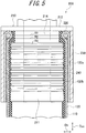
- FIG. 5 is a partial sectional view of the hydraulic actuator 10 including a sealing mechanism 200, cut along the axis direction D AX of the hydraulic actuator, according to Embodiment 1-1.
- the sealing member 210 has the first small diameter portion 214, of which outer diameter is smaller than that of the trunk portion 211, as described above.
- the first locking ring 220 is disposed on the outer side in the radial direction D R of the first small diameter portion 214.
- the inner diameter R1 of the first locking ring 220 is smaller than the outer diameter R3 of the trunk portion 211.
- the outer diameter R2 of the first locking ring 220 may also be smaller than the outer diameter R3 of the trunk portion 211.
- the tube 110 has a laminated structure including two or more rubber layers constituted of a polar rubber layer and a non-polar rubber layer (not shown).
- the trunk portion 211 is inserted into the tube 110 such that the tube 110 is in contact with the flange portion 212.
- the sleeve 120 is folded on the outer side in the radial direction D R and then backward via the first locking ring 220.
- the sleeve 120 has a first folded-back portion 120a, which has been folded backward by way of the first locking ring 220 at the end in the axis direction D AX of the actuator.
- the sleeve 120 includes: a sleeve main body 120b covering the outer peripheral surface of the tube 110; and the first folded-back portion 120a folded backward at the end in the axis direction D AX of the sleeve main body 120b to be disposed on the outer peripheral side of the sleeve main body 120b.
- the first folded-back portion 120a is attached to the sleeve main body 120b situated on the outer side in the radial direction D R of the tube 110.
- an adhesive layer 240 is formed between the sleeve main body 120b and the first folded-back portion 120a, so that the sleeve main body 120b and the first folded-back portion 120a are fixedly attached to each other by the adhesive layer 240.
- An appropriate adhesive can be used for the adhesive layer 240 in accordance with the type of the cords constituting the sleeve 120.
- the adhesive layer 240 is not essentially needed in the present disclosure and it is acceptable that the first folded-back portion 120a is not fixedly attached to the sleeve main body 120b.
- the trunk portion 211 of the sealing member 210 is inserted into the caulking member 230 having an inner diameter larger than the outer diameter of the trunk portion 211 and then the caulking member is caulked by the jig members.
- the caulking member 230 caulks the actuator main body 100 in collaboration with the sealing member 210.
- the caulking member 230 caulks the tube 110 having the trunk portion 211 inserted therein, the sleeve main body 120b, and the first folded-back portion 120a. That is, the caulking member 230 caulks the tube 110, the sleeve main body 120b, and the first folded-back portion 120a in collaboration with the sealing member 210.
- FIG. 6 is a partial sectional view of the hydraulic actuator 10 including a sealing mechanism 200, cut along the axis direction D AX of the hydraulic actuator, according to Embodiment 1-2.
- Embodiment 1-2 will be described mainly in regard to differences between Embodiment 1-1 and itself.
- a sheet-like elastic member is provided between the first folded-back portion 120a of the sleeve 120 and the caulking member 230.
- a rubber sheet 250 is provided between the first folded-back portion 120a and the caulking member 230.
- the rubber sheet 250 is provided so as to cover an outer peripheral surface of the cylindrical first folded-back portion 120a.
- the type of rubber sheet 250 is not particularly restricted.
- a rubber material similar to the rubber of the tube 110 may be used for the rubber sheet 250.
- the caulking member 230 caulks the actuator main body 100 including the rubber sheet 250 in collaboration with the sealing member 210.
- FIG. 7 is a partial sectional view of the hydraulic actuator 10 including a sealing mechanism 200, cut along the axis direction D AX of the hydraulic actuator, according to Embodiment 1-3.
- a rubber sheet 260 is used in place of the adhesive layer 240 of Embodiment 1-1.
- the rubber sheet 260 is a sheet-like elastic member and provided between the sleeve main body 120b and the first folded-back portion 120a.
- a rubber material similar to the rubber of the rubber sheet 250 may be used for the rubber sheet 260.
- FIG. 8 is a partial sectional view of the hydraulic actuator 10 including a sealing mechanism 200A, cut along the axis direction D AX of the hydraulic actuator, according to Embodiment 2-1.
- a sealing mechanism 200A is used in place of the sealing mechanism 200 of Embodiments 1-1, 1-2 and 1-3.
- the sealing mechanism 200A differs from the sealing mechanism 200 in that the former lacks the first small diameter portion 214 formed in the latter.
- the sealing mechanism 200A includes a sealing member 210A, a first locking ring 220A, and a caulking member 230A.
- a trunk portion 211A of the sealing member 210A is inserted into the tube 110 having a laminated structure including two or more rubber layers constituted of a polar rubber layer and a non-polar rubber layer (not shown). Since the sealing member 210A lacks the first small diameter portion 214 provided in the sealing member 210, the diameter of the first locking ring 220A is larger than the outer diameter of the entire trunk portion 211A. Accordingly, the first locking ring 220A is held by the flange portion 212A and the caulking member 230A between the flange portion 212A and the caulking member 230A.
- the caulking member 230A is not in contact with the flange portion 212A. That is, the first locking ring 220A is exposed to the exterior at the portion thereof on which the sleeve 120 is folded backward. Further, the first locking ring 220A need not be split like the first locking ring 220 of the embodiments 1-1, 1-2 and 1-3 because the diameter of the first locking ring 220A is safely larger than the outer diameter of the entire trunk portion 211A.
- An adhesive layer 240 is formed between the sleeve main body 120b and the first folded-back portion 120a in the present embodiment, as in Embodiment 1-1.
- FIG. 9 is a partial sectional view of the hydraulic actuator 10 including a sealing mechanism 200A, cut along the axis direction D AX of the hydraulic actuator, according to Embodiment 2-2.
- Embodiment 2-2 will be described mainly in regard to differences between Embodiment 2-1 and itself.
- a sheet-like elastic member is provided between the first folded-back portion 120a of the sleeve 120 and the caulking member 230A.
- a rubber sheet 250A is provided between the first folded-back portion 120a and the caulking member 230A.
- the rubber sheet 250A is provided so as to cover an outer peripheral surface of the cylindrical first folded-back portion 120a as the rubber sheet 250 does in Embodiment 1-2.
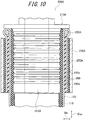
- FIG. 10 is a partial sectional view of the hydraulic actuator 10 including a sealing mechanism 200A, cut along the axis direction D AX of the hydraulic actuator, according to Embodiment 2-3.
- a rubber sheet 260 is used in place of the adhesive layer 240 of Embodiment 2-1.
- the rubber sheet 260 is a sheet-like elastic member and provided between the sleeve main body 120b and the first folded-back portion 120a, as in Embodiment 1-3.
- FIG. 11 is a partial sectional view of the hydraulic actuator 10 including a sealing mechanism 200B, cut along the axis direction D AX of the hydraulic actuator, according to Embodiment 3-1.
- Embodiment 3-1 and Embodiment 3-2 employ two locking rings.
- the sealing mechanism 200B includes a sealing member 210B, a first locking ring 220B, a caulking member 230B, and a second locking ring 270, as shown in FIG. 11 .
- the sealing mechanism 200B includes the second locking ring 270, as well as the first locking ring 220B, as described above.
- the second locking ring 270 fixedly holds the sleeve 120 at a position on the outer side in the radial direction D R of a trunk portion 211B and closer to the center in the axis direction D AX of the actuator main body 100 than the first locking ring 220B.
- the sealing member 210B has a second small diameter portion 216B, of which outer diameter is smaller than that of the trunk portion 211B.
- the second locking ring 270 is provided on the outer side in the radial direction D R of the second small diameter portion 216B.
- the inner diameter of the second locking ring 270 is preferably smaller than the outer diameter of the trunk portion 211B.
- the outer diameter of the second locking ring 270 may also be smaller than the outer diameter of the trunk portion 211B. Due to this structure, the second locking ring 270 is fixedly engaged with the second small diameter portion 216B.
- the sleeve 120 has a second folded-back portion 120c, which has been folded forward by way of the second locking ring 270.
- the second folded-back portion 120c is continuous with the first folded-back portion 120a.
- the second folded-back portion 120c is folded forward at an end in the axis direction D AX of the first folded-back portion 120a to be disposed on the outer peripheral side of the first folded-back portion 120a.
- the sleeve 120 folded toward the center side in the axis direction D AX of the actuator main body 100 by way of the first locking ring 220B, forms the first folded-back portion 120a.
- the first folded-back portion 120a of the sleeve 120 is then folded on the side of the end portion in the axis direction D AX of the actuator main body 100, thereby forming the second folded-back portion 120c.
- the caulking member 230B caulks the tube 110 having the trunk portion 211B inserted therein, the sleeve main body 120b situated on the outer side in the radial direction D R of the tube 110, the first folded-back portion 120a, and the second folded-back portion 120c in collaboration with the sealing member 210B.
- the rubber sheet 260 is provided between the sleeve main body 120b and the first folded-back portion 120a, as in Embodiment 1-3.
- a sheet-like elastic member is provided between the first folded-back portion 120a and the second folded-back portion 120c, as well.
- a rubber sheet 280 is provided between the first folded-back portion 120a and the second folded-back portion 120c. The rubber sheet 280 is provided so as to cover an outer peripheral surface of the cylindrical first folded-back portion 120a.
- a rubber sheet 290 having a configuration similar to that of the rubber sheet 250 of Embodiment 1-3 is provided between the second folded-back portion 120c and the caulking member 230B.
- the rubber sheet 290 is provided so as to cover an outer peripheral surface of the cylindrical second folded-back portion 120c.
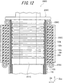
- FIG. 12 is a partial sectional view of the hydraulic actuator 10 including a sealing mechanism 200C, cut along the axis direction D AX of the hydraulic actuator, according to Embodiment 3-2.
- Embodiment 3-2 will be described mainly in regard to differences between Embodiment 3-1 and itself.
- Embodiment 3-2 employs a sealing member 210C in which neither the first small diameter portion 214B nor the second small diameter portion 216B is formed.
- the sealing member 210C has a trunk portion 211C. Since neither the first small diameter portion 214B nor the second small diameter portion 216B of the sealing member 210B is formed in the sealing member 210C, the inner diameter of the first locking ring 220C and the inner diameter of the second locking ring 270C are larger than the outer diameter of the trunk portion 211C, respectively.
- the caulking member 230C is positioned between the first locking ring 220C and the second locking ring 270C in the axis direction D AX . Accordingly, the first locking ring 220C and the second locking ring 270C are exposed to the exterior at the portions thereof on which the sleeve 120 is folded backward/forward.
- a rubber sheet 281 having a configuration similar to that of the rubber sheet 280 of Embodiment 3-1 is provided between the first folded-back portion 120a and the second folded-back portion 120c.
- a rubber sheet 291 having a configuration similar to that of the rubber sheet 290 of Embodiment 3-1 is provided between the second folded-back portion 120c of the sleeve 120 and the caulking member 230C.
- the tube 110 has a laminated structure including two or more rubber layers, the rubber layers being constituted of at least one polar rubber layer 111 containing, with respect to a rubber component(s) thereof, ⁇ 50 mass % of a polar rubber of which SP value is ⁇ 8.7 and at least one non-polar rubber layer 112 containing, with respect to a rubber component(s) thereof, ⁇ 50 mass % of a polar rubber of which SP value is ⁇ 8.7.
- Type of the polar rubber having SP value equal to or higher than 8.7 is not particularly restricted and examples of the polar rubber include acrylonitrile-butadiene rubber (NBR, which may occasionally be referred to as “nitrile rubber” hereinafter), hydrogenated acrylonitrile-butadiene rubber (hydrogenated NBR, which may occasionally be referred to as “hydrogenated nitrile rubber” hereinafter), chloroprene rubber (CR), epichlorohydrin rubber, and the like.
- NBR acrylonitrile-butadiene rubber
- hydrogenated NBR hydrogenated acrylonitrile-butadiene rubber
- chloroprene rubber CR
- epichlorohydrin rubber epichlorohydrin rubber
- the polar rubber layer 111 preferably contains acrylonitrile-butadiene rubber and/or hydrogenated acrylonitrile-butadiene rubber.
- Acrylonitrile-butadiene rubber and hydrogenated acrylonitrile-butadiene rubber exhibit particularly high oil resistance, as well as good workability, among the polar rubbers described above. Accordingly, in a case where the polar rubber layer 111 contains acrylonitrile-butadiene rubber and/or hydrogenated acrylonitrile-butadiene rubber, oil resistance of the polar rubber layer 111 further improves.
- the acrylonitrile-butadiene rubber and the hydrogenated acrylonitrile-butadiene rubber contain acrylonitrile units therein by 20 mass % to 50 mass %, respectively, because then oil resistance of the polar rubber layer 111 further improves.
- Acrylonitrile-butadiene rubber and/or hydrogenated acrylonitrile-butadiene rubber is generally classified into the low nitrile content type having content of acrylonitrile units less than 25 mass %, the intermediate nitrile content type having content of acrylonitrile units of ⁇ 25 mass % and ⁇ 35 mass %, and the high nitrile content type having content of acrylonitrile units equal to or higher than 35 mass %.
- the acrylonitrile-butadiene rubber and/or the hydrogenated acrylonitrile-butadiene rubber include at least two types of acrylonitrile-butadiene rubber and/or hydrogenated acrylonitrile-butadiene rubber having different contents of acrylonitrile units.
- a desired nitrile content can be easily achieved by using at least two types of acrylonitrile-butadiene rubber and/or hydrogenated acrylonitrile-butadiene rubber.
- the content of acrylonitrile-butadiene rubber (NBR) and hydrogenated acrylonitrile-butadiene rubber (hydrogenated NBR) in a rubber component(s) of the polar rubber layer 111 is preferably in the range of 50 mass % to 100 mass % and more preferably in the range of 60 mass % to 90 mass %.
- Hydrogenated acrylonitrile-butadiene rubber is obtained by adding hydrogen to acrylonitrile-butadiene rubber.
- Hydrogenated acrylonitrile-butadiene rubber is preferable because it generally has oil resistance equivalent to that of acrylonitrile-butadiene rubber and exhibits better heat resistance than acrylonitrile-butadiene rubber.
- Chloroprene rubber is preferable among the polar rubbers described above because it is excellent in mechanical properties such as tensile strength, elongation, as well as workability.
- Epichlorohydrin rubber is preferable among the polar rubbers described above because it is excellent in ozone resistance and adhesion property.
- the polar rubber layer 111 contains a polar rubber having SP value equal to or higher than 8.7 by at least 50 mass %, preferably in the range of 60 mass % to 100 mass %, and more preferably in the range of 60 mass % to 95 mass %, in the rubber component(s) thereof. Setting the content of a polar rubber in the polar rubber layer 111 to be within the aforementioned range further improves oil resistance of the polar rubber layer 111.
- the non-polar rubber layer 112 contains a polar rubber having SP value equal to or higher than 8.7 by less than 50 mass %, preferably in the range of 0 mass % to 10 mass %, in the rubber components thereof. Setting the content of a polar rubber in the non-polar rubber layer 112 to be within the aforementioned range ensures an increase in content of a non-polar rubber having SP value less than 8.7 in the non-polar rubber layer 112.
- the polar rubber layer 111 has the weighted average nitrile content in the rubber component(s) thereof preferably in the range of ⁇ 20 mass % and ⁇ 45 mass %. In this case, oil resistance of the polar rubber layer 111 further enhances, whereby durability of the tube further improves.
- the polar rubber layer 111 and the non-polar rubber layer 112 may contain, as a rubber component thereof, a rubber other than the polar rubber having SP value equal to or higher than 8.7 described above, for example, a non-polar diene-based rubber having SP value less than 8.7.
- non-polar diene-based rubber having SP value less than 8.7 examples include butadiene rubber (BR).
- BR butadiene rubber
- Vinyl cis-polybutadiene rubber (VC-BR) is preferable in particular.
- VC-BR is a rubber constituted of polybutadiene including cis-1,4 units as repeating units thereof and polybutadiene including 1,2-vinyl units as repeating units thereof.
- a proportion of the cis-1,4 units in microstructures other than 1,2-vinyl units, of VC-BR, is generally equal to or higher than 97 mass %.
- Mechanical strength of the polar rubber layer 111 enhances when the polar rubber layer 111 contains VC-BR.
- the non-polar rubber layer 112 containing a polar rubber having SP value equal to or higher than 8.7 by less than 50 mass % in the rubber component(s) thereof as described above, naturally contains other rubber component(s).
- the other rubber components include butadiene rubber (BR), natural rubber (NR), synthetic isoprene rubber (IR), styrene-butadiene rubber (SBR), butyl rubber, and the like. Crack resistance, wear resistance and slidability of the non-polar rubber layer 112 improve and thus durability of the tube further improves when the non-polar rubber layer 112 contains the aforementioned other rubber component(s).
- the polar rubber layer 111 and the non-polar rubber layer 112 preferably contain, in addition to the rubber components described above, at least one material selected from the group consisting of polyvinyl chloride (PVC), zinc polyacrylate, and an aliphatic resin, depending on an intended application. Mechanical strength of the tube enhances when the polar rubber layer and the non-polar rubber layer contain these materials.
- the aliphatic resin include a polyolefin-based resin.
- the polar rubber layer 111 and the non-polar rubber layer 112 may contain, in addition to the aforementioned rubber components, yet other compounding agents.
- other compounding agents include carbon black, silica, zinc white, stearic acid, anti-oxidant, plasticizer, sulfur, scorch-preventing agent, vulcanization accelerator, organic peroxide, and the like.
- the polar rubber layer 111 and the non-polar rubber layer 112 preferably contain carbon black. Strength of the polar rubber layer 111 and the non-polar rubber layer 112 enhances and thus durability of the tube 110 improves when the polar rubber layer 111 and the non-polar rubber layer 112 contain carbon black. Content of carbon black is preferably in the range of 5 to 70 parts by mass, more preferably in the range of 30 to 70 parts by mass, and further more preferably in the range of 40 to 60 parts by mass, with respect to 100 parts by mass of the rubber components.
- content of carbon black in the polar rubber layer 111 is preferably in the range of 5 to 50 parts by mass, more preferably in the range of 5 to 45 parts by mass, and further more preferably in the range of 5 to 30 parts by mass, with respect to 100 parts by mass of the rubber component(s) in the polar rubber layer 111.
- Strength of the tube 110 further enhances and thus durability of the tube 110 further improves when the content of carbon black in the polar rubber layer 111 is equal to or higher than 5 parts by mass with respect to 100 parts by mass of the rubber component(s) in the polar rubber layer 111.
- Durability of the tube 110 further improves when the content of carbon black in the polar rubber layer 111 is equal to or lower than 50 parts by mass with respect to 100 parts by mass of the rubber component(s) in the polar rubber layer 111 because then elongation at break (Eb) of the tube 110 increases.
- Content of carbon black in the non-polar rubber layer 112 is preferably in the range of 5 to 70 parts by mass, more preferably in the range of 25 to 50 parts by mass, with respect to 100 parts by mass of the rubber component(s) in the non-polar rubber layer 112.
- Type of the carbon black is not particularly restricted and examples thereof include carbon black products of GPF, FEF, HAF, ISAF, SAF grades. These carbon black products can be used by either a single type or two or more types in combination.
- the carbon black contained in the non-polar rubber layer 112 has the nitrogen adsorption specific surface area preferably in the range of 34 m 2 /g to 155 m 2 /g, more preferably in the range of 40 m 2 /g to 155 m 2 /g, further more preferably in the range of 70 m 2 /g to 145 m 2 /g. Setting the nitrogen adsorption specific surface area of carbon black contained in the non-polar rubber layer 112 to be within the aforementioned ranges further improves crack resistance, wear resistance and slidability of the non-polar rubber layer 112.
- type of the carbon black contained in the polar rubber layer 111 is not particularly restricted.
- the nitrogen adsorption specific surface area of carbon black contained in the polar rubber layer 111 is preferably in the range of 70 m 2 /g to 145 m 2 /g. Setting the nitrogen adsorption specific surface area of carbon black contained in the polar rubber layer 111 to be within the aforementioned ranges further improves strength of the polar rubber layer 111.
- the polar rubber layer 111 may further contain silica.
- Content of silica is preferably in the range of 5 to 20 parts by mass, more preferably in the range of 5 to 10 parts by mass, with respect to 100 parts by mass of the rubber component(s) in the polar rubber layer 111.
- Strength of the tube 110 enhances and thus crack propagation resistance of the tube 110 is made satisfactorily high when the content of silica in the polar rubber layer 111 is equal to or higher than 5 parts by mass with respect to 100 parts by mass of the rubber component(s) in the polar rubber layer 111.
- the crack propagation resistance of the tube 110 can be further improved by setting the content of silica in the polar rubber layer 111 to be equal to or lower than 20 parts by mass with respect to 100 parts by mass of the rubber component(s) in the polar rubber layer 111.
- Type of the silica is not particularly restricted and examples thereof include wet silica (hydrated silica), dry silica (anhydrous silica), calcium silicate, aluminum silicate, and the like. Wet silica is preferable among these examples. These silicas can be used by either a single type or two or more types in combination.
- the polar rubber layer 111 may further contain a silane coupling agent.
- Content of the silane coupling agent is preferably in the range of 0.1 parts by mass or less with respect to 100 parts by mass of the silica described above. It is acceptable that the polar rubber layer does not contain a silane coupling agent. That is, content of the silane coupling agent in the polar rubber layer 111 is preferably in the range of 0 to 0.1 parts by mass with respect to 100 parts by mass of the silica.
- Silica and the rubber component form covalent bonds therebetween (i.e. bound rubber is formed), whereby hysteresis loss is reduced, when a silane coupling agent is added to the polar rubber layer.
- the lower content of a silane coupling agent is the better.
- the content of the silane coupling agent ⁇ 0.1 parts by mass with respect to 100 parts by mass of the silica ensures occurrence of energy loss when a rubber component is peeled off from silica surfaces upon application of stress strain, thereby further improving crack propagation resistance of the polar rubber layer 111. Accordingly, it is particularly preferable that the polar rubber layer contains no silane coupling agent.
- the non-polar rubber layer 112 preferably further contains silica.
- Strength of the non-polar rubber layer 112 enhances and thus durability of the tube 110 improves when the non-polar rubber layer 112 contains silica.
- Content of silica is preferably in the range of 10 to 30 parts by mass, more preferably in the range of 15 to 25 parts by mass, with respect to 100 parts by mass of the rubber component(s) in the non-polar rubber layer 112.
- Type of the silica is not particularly restricted and examples thereof include wet silica (hydrated silica), dry silica (anhydrous silica), calcium silicate, aluminum silicate, and the like. Wet silica is preferable among these examples. These silicas can be used by either a single type or two or more types in combination.
- the non-polar rubber layer 112 contains silica
- Strength of the non-polar rubber layer 112 enhances and thus durability of the tube 110 improves when the non-polar rubber layer 112 contains a silane coupling agent, as well as silica.
- Content of the silane coupling agent is preferably in the range of 1 to 15 parts by mass, more preferably in the range of 2 to 10 parts by mass, with respect to 100 parts by mass of the silica.
- Type of the silence coupling agent is not particularly restricted and examples thereof include bis(3-triethoxysilylpropyl) tetrasulfide, bis(3-triethoxysilylpropyl) trisulfide, bis(3-triethoxysilylpropyl) disulfide, bis(2-triethoxysilylethyl) tetrasulfide, bis(3-trimethoxysilylpropyl) tetrasulfide, bis(2-trimethoxysilylethyl) tetrasulfide, (3-mercaptopropyl)trimethoxysilane, (3-mercaptopropyl)triethoxysilane, (2-mercaptoethyl)trimethoxysilane, (2-mercaptoethyl)triethoxysilane, 3-trimethoxysilylpropyl-N,N-dimethylthiocarbamoyl tetrasulf
- Examples of the anti-oxidant include N-phenyl-N'-(1,3-diphenylbutyl)-p-phenylenediamine, N-phenyl-N'-(1,3-dimethylbutyl)-p-phenylenediamine, and the like.
- Examples of the plasticizer include oil, and the like.
- Examples of the scorch-preventing agent include N-(cyclohexylthio)phthalimide, and the like.
- vulcanization accelerator examples include N-cyclohexyl-2-benzothiazolylsulfenamide (CBS), 1,3-diphenylguanidine (DPG), tetrakis(2-ethylhexyl)thiuram disulfide (TOT), di-2-benzothiazolyl disulfide (MBTS), and the like.
- CBS N-cyclohexyl-2-benzothiazolylsulfenamide
- DPG 1,3-diphenylguanidine
- TOT tetrakis(2-ethylhexyl)thiuram disulfide
- MBTS di-2-benzothiazolyl disulfide
- the polar rubber layer 111 has elongation at break (Eb) preferably ⁇ 500%, more preferably ⁇ 800%, and further more preferably ⁇ 1000%.
- Setting elongation at break (Eb) of the polar rubber layer 111 to be ⁇ 500% enhances durability against repetitive deformation of a relatively large magnitude and suppresses crack generation and crack propagation speed, thereby further successfully improving crack propagation resistance of the polar rubber layer 111.
- elongation at break (Eb) is a value measured according to JIS K 6251.
- the non-polar rubber layer 112 has tensile stress at 100% elongation (M100) preferably ⁇ 1.0 MPa, more preferably ⁇ 1.5 MPa, and preferably ⁇ 5.0 MPa. Provision of the non-polar rubber layer 112 having tensile stress at 100% elongation (M100) ⁇ 1.0 MPa successfully prevents excess expansion from occurring even when elongation at break (Eb) of the polar rubber layer 111 is ⁇ 500%, thereby further improving durability of the actuator. The tensile stress at 100% elongation (M100) ⁇ 5.0 MPa ensures satisfactory functionality and operability of the actuator.
- the tube 110 having a laminated structure including the polar rubber layer 111 and the non-polar rubber layer 112 by, for example: blending the rubber components and the compounding agents described above, to prepare a rubber composition for a polar rubber layer and a rubber composition for a non-polar rubber layer, respectively; and subjecting these rubber composition to coextrusion by using an extrusion molding apparatus.
- a rubber composition was prepared by mixing and kneading by a Banbury mixer the rubber components and the compounding agents according to the blending formulations shown in Tables 1 and 2. Elongation at break (Eb) and tensile stress at 100% elongation (M100) were measured, respectively, by the methods described below for each of the rubber compositions thus obtained.
- Tensile stress at 100% elongation (M100) and elongation at break (Eb) were measured, respectively, by: subjecting each of the rubber compositions thus obtained to extrusion by 3-inch rolls and then vulcanizing press, thereby manufacturing a sheet-like body (width: 75 mm, length: 150 mm, thickness: 2 mm); preparing JIS K 6251 dumbbell-shaped No. 3 samples from the sheet-like body; and conducting tensile tests at 25°C according to JIS K 6251, to measure tensile stress at 100% elongation (M100) and elongation at break (Eb) values of the samples.
- the results are shown in Table 1 and Table 2.
- Test tubes each having a cylindrical configuration were prepared by processing the rubber compositions thus obtained, by an extrusion molding machine, respectively.
- a tube having a two-layered structure constituted of an inner layer and an outer layer, as shown in FIG. 3 was prepared for each of Examples 1-27 and Comparative Examples 6, 7.
- a tube having a single-layer structure was prepared for each of Comparative Examples 1-5.
- the formulation of the rubber composition used in each outer/inner layer, the outer diameter and the inner diameter, a proportion of the inner layer thickness with respect to the tube thickness, and a proportion of the outer layer thickness with respect to the tube thickness, of each test tube, are shown in Table 3 and Table 4.
- Test sleeves each having a woven structure were prepared by weaving the 64 aramid fiber cords thus obtained, respectively.
- Each test sleeve had a cylindrical, woven structure wherein the 64 aramid fiber cords were observed along a circumference of a cross section thereof.
- each test sleeve had a cylindrical, woven structure constituted of one group of 32 aramid fiber cords disposed in parallel to each other at equal intervals therebetween to collectively form a spiral configuration and the other group of 32 aramid fiber cords disposed in parallel to each other at equal intervals therebetween to collectively form another spiral configuration so as to intersect the one group of 32 aramid fiber cords.
- the one group of 32 aramid fiber cords and the other group of 32 aramid fiber cords were woven to intersect each other alternately to collectively form the test sleeve.
- the angle formed by each cord with respect to the axis direction of the sleeve was 25°.
- Test actuators each having the structures shown in FIGS. 1 and 2 were prepared by using the test tubes and the test woven sleeves described above, respectively.
- the length between the sealing mechanism 200 and a sealing mechanism 300 was 250 mm in each test actuator.
- "UF46" of COSMO SUPER EPOCH was used as hydraulic oil for the tube integrated in the test actuator. Durability of each of the test actuators thus prepared was evaluated by the methods described below. The results are shown in Tables 3 and 4.
- Durability of each test actuator was determined by: injecting the hydraulic oil into the tube and completely substituting air in the tube with the hydraulic oil; then controlling injection of the hydraulic oil such that the pressure of the hydraulic oil in the tube reciprocally changes between 0 MPa and 5 MPa in an alternate and repetitive manner at every 3 second; counting the number of injections until cracks were generated and propagated in the tube and the actuator could no longer function; and expressing the count number as an index value relative to the count number of Comparative Example 1 being "100" in Table 3 and as an index value relative to the count number of Example 25 being "100” in Table 4. The larger index value represents the higher durability (crack propagation resistance).
- Example 1 Example 2
- Example 3 Example 4
- Example 5 Example 6
- Example 7 Example 8
- Example 9 Example 10
- Example 12 Example 13 Structure of tube Two-layered Two-layered Two-layered Two-layered Two-layered Two-layered Two-layered Two-layered Two-layered Two-layered Two-layered Two-layered Two-layered Two-layered Two-layered Two-layered Two-layered Two-layered Two-layered Two-layered Two-layered Two-layered Formulation of inner layer rubber of tube Polar rubber composition 1 Polar rubber composition 1 Polar rubber composition 1 Polar rubber composition 1 Polar rubber composition 4
- Polar rubber composition 1 Polar rubber composition 1 Polar rubber composition 2
- Polar rubber composition 3 Polar rubber composition 6
- Polar rubber composition 6 Formuaton of outer layer rubber of tube Non-Polar rubber composition 1 Non-Polar rubber composition 2 Non-Polar rubber composition 3 Non-Polar rubber composition 4 Non-Polar rubber composition 5
- durability of the hydraulic actuator further improves when the polar rubber layer contains silica and content of the silica is in the range of 5 to 20 parts by mass with respect to 100 parts by mass of the rubber components in the polar rubber layer.
Landscapes
- Engineering & Computer Science (AREA)
- Physics & Mathematics (AREA)
- Fluid Mechanics (AREA)
- Mechanical Engineering (AREA)
- General Engineering & Computer Science (AREA)
- Chemical & Material Sciences (AREA)
- Analytical Chemistry (AREA)
- Actuator (AREA)
Abstract
Description
- The present invention relates to a hydraulic actuator.
- Conventionally, there has been widely used as an actuator for expanding/contracting a tube a pneumatic actuator having a rubber tube (a tube-shaped body) capable of expanding/contracting by using air as working fluid and a sleeve (a woven reinforcing structure) covering an outer peripheral surface of the tube, i.e. a McKibben type actuator (refer to PTL1, for example).
- Respective end portions of an actuator main body constituted of a tube and a sleeve as described above are caulked by using a sealing member formed by metal.
- The sleeve is a cylindrical structure formed by woven high tensile strength fiber cords such as polyamide fibers or metal cords, for regulating expansion movements of the tube within a predetermined range.
- Such a pneumatic actuator as described above, which is used in various fields, is suitably used as an artificial muscle for a nursing care/healthcare device in particular.
- PTL 1:
JP S61-236905 A - However, such a conventional actuator as described above using air as working fluid does not have particularly high strength (pressure resistance), which strength is only around 0.5 MPa at most, for example.
- In this respect, durability of the conventional actuator is not satisfactory when it is employed as a hydraulic actuator using liquid such as oil, water or the like as working fluid because a hydraulic actuator is generally subjected to high pressure, e.g. 50 MPa. In particular, a tube adjacent to a sleeve of the conventional actuator bears relatively large load because of repeated expansion-contraction motions of the actuator, thereby necessitating further improvement in terms of durability of the tube.
- In view of this, an object of the present disclosure is to solve the prior art problems described above and provide a hydraulic actuator using liquid as working fluid, and having a tube which exhibits improved durability.
- Primary features of the present disclosure for achieving the aforementioned object are as follows.
- A hydraulic actuator of the present disclosure has an actuator main body constituted of a cylindrical tube capable of expanding/contracting by hydraulic pressure and a sleeve for covering an outer peripheral surface of the tube, the sleeve having a cylindrical structure formed by cords woven to be disposed in predetermined directions, wherein:
- the tube has a laminated structure including two or more rubber layers, the rubber layers being constituted of at least one polar rubber layer containing, with respect to a rubber component(s) thereof, ≥ 50 mass % of a polar rubber of which SP value is ≥ 8.7 and at least one non-polar rubber layer containing, with respect to a rubber component(s) thereof, < 50 mass % of a polar rubber of which SP value is ≥ 8.7.
- The hydraulic actuator according to the present disclosure exhibits improved durability of a tube thereof and thus has high durability as an actuator.
- In the present disclosure, SP (solubility parameter) value of a rubber component such as a polar rubber, a non-polar rubber and the like is calculated according to Fedors' method. The unit of the SP value is "(cal/cm3)1/2".
- In the present disclosure, a rubber having SP value ≥ 8.7 is defined as a "polar rubber" and a rubber having SP value < 8.7 is defined as a "non-polar rubber".
- Further, in the present disclosure, a rubber layer containing, with respect to a rubber component(s) thereof, ≥ 50 mass % of a polar rubber of which SP value is ≥ 8.7 is defined as a "polar rubber layer" and a rubber layer containing, with respect to a rubber component(s) thereof, < 50 mass % of a polar rubber of which SP value is ≥ 8.7 is defined as a "non-polar rubber layer".
- In a preferable example of the hydraulic actuator of the present disclosure, the polar rubber layer is provided on the innermost side of the tube. In this case, oil resistance of the tube improves, whereby durability of the tube further improves.
- In another preferable example of the hydraulic actuator of the present disclosure, the non-polar rubber layer is provided on the outer side in the radial direction of the polar rubber layer and on the outermost side of the tube. In this case, strength of the tube enhances, whereby durability of the tube further improves.
- In yet another preferable example of the hydraulic actuator of the present disclosure, the polar rubber layer contains acrylonitrile-butadiene rubber and/or hydrogenated acrylonitrile-butadiene rubber. In this case, oil resistance of the polar rubber layer improves, whereby durability of the tube further improves.
- In this respect, it is preferable that the acrylonitrile-butadiene rubber and/or the hydrogenated acrylonitrile-butadiene rubber contains acrylonitrile units therein by 20 mass % to 50 mass %. In this case, oil resistance of the polar rubber layer further enhances, whereby durability of the tube further improves.
- Further, it is preferable that the acrylonitrile-butadiene rubber and/or the hydrogenated acrylonitrile-butadiene rubber include at least two types of acrylonitrile-butadiene rubber and/or hydrogenated acrylonitrile-butadiene rubber having different contents of acrylonitrile units therein. In this case, the content of acrylonitrile units in the polar rubber layer can be easily adjusted to a desired value.
- In the hydraulic actuator of the present disclosure, it is preferable that the polar rubber layer contains a non-polar diene-based rubber having SP value less than 8.7. In this case, strength of the polar rubber layer enhances, whereby durability of the tube further improves.
- In the hydraulic actuator of the present disclosure, the polar rubber layer has the weighted average nitrile content in the rubber component(s), which is preferably in the range of ≥ 20% and ≤ 45%. In this case, oil resistance of the polar rubber layer enhances, whereby durability of the tube further improves.
- In yet another preferable example of the hydraulic actuator of the present disclosure, the non-polar rubber layer contains at least one selected from the group consisting of butadiene rubber, natural rubber, synthetic isoprene rubber, styrene-butadiene rubber, and butyl rubber. In this case, strength of the non-polar rubber layer enhances, whereby durability of the tube further improves.
- In yet another preferable example of the hydraulic actuator of the present disclosure, the polar rubber layer and the non-polar rubber layer contain carbon black. In this case, strength of the polar rubber layer and the non-polar rubber layer enhances, whereby durability of the tube further improves.
- In this respect, it is preferable that the carbon black contained in the non-polar rubber layer has the nitrogen adsorption specific surface area in the range of 34 m2/g to 155 m2/g. In this case, strength of the non-polar rubber layer further enhances, whereby durability of the tube further improves.
- In the present disclosure, the nitrogen adsorption specific surface area (N2SA) of the carbon black is measured according to JIS K6217-2: 2001.
- In yet another preferable example of the hydraulic actuator of the present disclosure, the non-polar rubber layer further contains silica. In this case, strength of the non-polar rubber layer further enhances, whereby durability of the tube further improves.
- In this respect, it is preferable that the non-polar rubber layer further contains a silane coupling agent. In this case, strength of the non-polar rubber layer further enhances, whereby durability of the tube further improves.
- In yet another preferable example of the hydraulic actuator of the present disclosure, the polar rubber layer further contains silica by 5 to 20 parts by mass with respect to 100 parts by mass of the rubber component(s) in the polar rubber layer. In this case, crack propagation resistance of the tube enhances, whereby durability of the actuator further improves.
- In this respect, it is preferable that the polar rubber layer contains a silane coupling agent by 0.1 parts by mass or less with respect to 100 parts by mass of the silica. In this case, crack propagation resistance of the tube further enhances.
- In yet another preferable example of the hydraulic actuator of the present disclosure, the total thickness of the polar rubber layer is 10% to 90% of the total thickness of the tube and the total thickness of the non-polar rubber layer is 90% to 10% of the total thickness of the tube. In this case, durability of the tube further improves.
- In the hydraulic actuator of the present disclosure, the non-polar rubber layer has tensile stress at 100% elongation (M100) equal to or higher than 1.0 MPa. In this case, durability of the tube can be further improved.
- In the present disclosure, tensile stress at 100% elongation (M100) is a value measured according to JIS K 6251.
- According to the present disclosure, it is possible to provide a hydraulic actuator having a tube which exhibits improved durability.
- In the accompanying drawings, wherein:
-
FIG. 1 is a side view of an embodiment of ahydraulic actuator 10. -
FIG. 2 is a partially exploded perspective view of an embodiment of thehydraulic actuator 10. -
FIG. 3 is a partial sectional view of an embodiment of atube 110. -
FIG. 4 is a partial sectional view of another embodiment of thetube 110. -
FIG. 5 is a partial sectional view of thehydraulic actuator 10 including asealing mechanism 200, cut along the axis direction DAX of the hydraulic actuator, according to Embodiment 1-1. -
FIG. 6 is a partial sectional view of thehydraulic actuator 10 including asealing mechanism 200, cut along the axis direction DAX of the hydraulic actuator, according to Embodiment 1-2. -
FIG. 7 is a partial sectional view of thehydraulic actuator 10 including asealing mechanism 200, cut along the axis direction DAX of the hydraulic actuator, according to Embodiment 1-3. -
FIG. 8 is a partial sectional view of thehydraulic actuator 10 including asealing mechanism 200A, cut along the axis direction DAX of the hydraulic actuator, according to Embodiment 2-1. -
FIG. 9 is a partial sectional view of thehydraulic actuator 10 including asealing mechanism 200A, cut along the axis direction DAX of the hydraulic actuator, according to Embodiment 2-2. -
FIG. 10 is a partial sectional view of thehydraulic actuator 10 including asealing mechanism 200A, cut along the axis direction DAX of the hydraulic actuator, according to Embodiment 2-3. -
FIG. 11 is a partial sectional view of thehydraulic actuator 10 including asealing mechanism 200B, cut along the axis direction DAX of the hydraulic actuator, according to Embodiment 3-1. -
FIG. 12 is a partial sectional view of thehydraulic actuator 10 including asealing mechanism 200C, cut along the axis direction DAX of the hydraulic actuator, according to Embodiment 3-2. - Hereinafter, the hydraulic actuator of the present disclosure will be demonstratively described in detail based on embodiments thereof and with reference to the drawings. The same functions and structures share the same/similar reference numerals and repetitive or redundant explanations thereof will be omitted.
-
FIG. 1 is a side view of ahydraulic actuator 10 according to an embodiment of the present disclosure. As shown inFIG. 1 , thehydraulic actuator 10 has an actuatormain body 100, asealing mechanism 200, and anothersealing mechanism 300.Respective connection portions 20 are provided at respective ends of thehydraulic actuator 10. - The actuator
main body 100 is constituted of atube 110 and asleeve 120. A working fluid flows into the actuatormain body 100 via a fitting 400 and apassage hole 410. The actuator of the present disclosure is hydraulically operated and uses a liquid as the working fluid. Examples of the liquid include oil, water, and the like. The actuator of the present disclosure may employ either oil pressure or water pressure. The actuator of the present disclosure, of whichtube 110 has high oil resistance, can be suitable used for an oil pressure system. In a case where the hydraulic actuator employs oil pressure, any suitable hydraulic oil which is conventionally used in a hydraulic driving system employing oil pressure may be used as hydraulic oil. - The actuator
main body 100, when the working fluid flows into thetube 110, contracts in the axis direction DAX and expands in the radial direction DR of the actuatormain body 100. On the other hand, the actuatormain body 100, when the working fluid flows out of thetube 110, expands in the axis direction DAX and contracts in the radial direction DR of the actuatormain body 100. Thehydraulic actuator 10 functions as an actuator by such changes in configuration of the actuatormain body 100 as described above. - Further, the
hydraulic actuator 10 as described above is what is called a McKibben type actuator, which is applicable to artificial muscles of course and can also be suitably used for limbs (upper limbs and lower limbs) of a robot, which limbs require higher capacity (contraction force) than artificial muscles. Theconnection portions 20 are connected to members constituting the limbs, or the like. - The
sealing mechanism 200 and thesealing mechanism 300 seal end portions of the actuatormain body 100 in the axis direction DAX thereof, respectively. Specifically, thesealing mechanism 200 includes a sealingmember 210 and acaulking member 230. The sealingmember 210 seals an end portion in the axis direction DAX of the actuatormain body 100. Thecaulking member 230 caulks the actuatormain body 100 in collaboration with the sealingmember 210.Indentations 231 as marks made by the caulking jigs are formed at an outer peripheral surface of thecaulking member 230. - Differences between the
sealing mechanism 200 and thesealing mechanism 300 reside in whether the fitting 400 (and the passage hole 410) is provided or not. - The fitting 400 protrudes such that the fitting 400 can be mounted to a driving pressure source of the
hydraulic actuator 10, or more specifically a hose (a piping path) connected to a compressor of the working fluid. The working fluid which has flowed into the actuator via the fitting 400 then flows into the inside of the actuatormain body 100, or more specifically the inside of thetube 110, via thepassage hole 410. -
FIG. 2 is a partially exploded perspective view of thehydraulic actuator 10. As shown inFIG. 2 , thehydraulic actuator 10 has the actuatormain body 100 and thesealing mechanism 200. - The actuator
main body 100 is constituted of thetube 110 and thesleeve 120, as described above. - The
tube 110 is a cylindrical, pipe-like member capable of expanding/contracting by hydraulic pressure. Thetube 110, which is to repeat contracting and expanding movements alternately by the working fluid, is made of an elastic material. In the present disclosure, thetube 110 has a laminated structure including two or more rubber layers constituted of at least one polar rubber layer and at least one non-polar rubber layer. The polar rubber layer contains, with respect to a rubber component(s) thereof, ≥ 50 mass % of a polar rubber of which SP value is ≥ 8.7 and the non-polar rubber layer contains, with respect to a rubber component(s) thereof, < 50 mass % of a polar rubber of which SP value is ≥ 8.7. -
FIG. 3 is a partial sectional view of an embodiment of atube 110.FIG. 4 is a partial sectional view of another embodiment of thetube 110. - The
tube 110 shown inFIG. 3 has a two-layered structure including: apolar rubber layer 111 provided on the inner surface side of the tube; and anon-polar rubber layer 112 provided on the outer surface side of thetube 110 to be adjacent to thepolar rubber layer 111 on the outer side in the radial direction DR of thepolar rubber layer 111. - The
polar rubber layer 111 contains, with respect to a rubber component(s) thereof, 50 mass % or more of a polar rubber of which SP value is 8.7 or more. Thepolar rubber layer 111 is therefore excellent in liquid resistance, in particular, oil resistance, thereby exhibiting high durability when a working fluid is oil, for example. - On the other hand, the
non-polar rubber layer 112 contains, with respect to a rubber component(s) thereof, less than 50 mass % of a polar rubber of which SP value is 8.7 or more. Thenon-polar rubber layer 112 is therefore excellent in crack resistance, wear resistance and slidability and capable of bearing load applied from thesleeve 120 side, thereby exhibiting high durability when thenon-polar rubber layer 112 is in contact with thesleeve 120. - That is, the
tube 110 having a laminated structure including two or more rubber layers constituted of thepolar rubber layer 111 and thenon-polar rubber layer 112 makes it possible to realize a hydraulic actuator having both high liquid resistance and high durability even after experiencing repeated expanding and contracting motions. - In the present disclosure, it is preferable that the
polar rubber layer 111 is provided on the innermost side of thetube 110. In a case where thepolar rubber layer 111 is provided on the innermost side of thetube 110, oil resistance of the tube improves, whereby durability of thetube 110 further improves. - Further, in the present disclosure, it is preferable that the
non-polar rubber layer 112 is provided on the outer side in the radial direction DR of thepolar rubber layer 111 and on the outermost side of thetube 110. In a case where thenon-polar rubber layer 112 is provided on the outer side in the radial direction DR of thepolar rubber layer 111, thenon-polar rubber layer 112 having excellent crack resistance, wear resistance and slidability bears load applied from thesleeve 120 side and protects thepolar rubber layer 111, whereby strength of the entire portion of thetube 110 enhances and thus durability of thetube 110 further improves. - In the present disclosure, the
tube 110 has a laminated structure including two or more rubber layers constituted of the polar rubber layer and the non-polar rubber layer, as described above. It means that thetube 110 may have a laminated structure including, for example, three or more rubber layers as shown inFIG. 4 (a four-layered structure inFIG. 4 ). - In this respect, in a case where the
tube 110 has a laminated structure including three or more rubber layers, it is preferable that thepolar rubber layer 111 is provided on the innermost side of thetube 110 and thenon-polar rubber layer 112 is provided on the outermost side of thetube 110. Thepolar rubber layer 111, provided on the innermost side of thetube 110 to be in direct contact with the working fluid, can most effectively exhibit high liquid resistance thereof. Thenon-polar rubber layer 112, provided on the outermost side of thetube 110 to be in direct contact with thesleeve 120, can most effectively exhibit high crack resistance, wear resistance and slidability thereof. - Although the
tube 110 shown inFIG. 3 and FIG. 4 is constituted of only thepolar rubber layer 111 and thenon-polar rubber layer 112, it is acceptable in the present disclosure to provide an adhesive layer between the polar rubber layer and the non-polar rubber layer so that adhesion between the polar rubber layer and the non-polar rubber layer improves. An adequate adhesive, selected in accordance with the characteristics of the polar rubber layer and the non-polar rubber layer, may be used for the adhesive layer. For example, "Metalock R-17" manufactured by TOYO KAGAKU KENKYUSHO CO., LTD. or the like can be suitably used. - Further, in the present disclosure, the total thickness of the
polar rubber layer 111 is preferably 10% to 90%, more preferably 20% to 80%, of the total thickness of thetube 110 and the total thickness of thenon-polar rubber layer 112 is preferably 90% to 10%, more preferably 80% to 20%, of the total thickness of thetube 110. In this case, liquid resistance and durability of thetube 110 improves, thereby further improving durability of the actuator. - The total thickness of the
tube 110, which may be appropriately set in accordance with an intended application, is preferably in the range of 1.0 mm to 6.0 mm in terms of durability and a maneuverable length of the actuator. The diameter (outer diameter) of thetube 110 may be appropriately set in accordance with an intended application. - The
sleeve 120 has a cylindrical configuration and covers an outer peripheral surface of thetube 110. Thesleeve 120 has a woven structure formed by weaving cords to be disposed in certain directions, wherein the cords thus disposed intersect each other in a woven manner to provide rhombus configurations in a repetitive and continuous manner. Thesleeve 120 having such a configuration as described above can deform like a pantograph and follow contraction/expansion of thetube 110, while also regulating the contraction/ expansion. - It is preferable to use, as the cord 121 of the
sleeve 120, a fiber cord made of at least one fiber material selected from the group consisting of: polyamide fibers such as aramid fiber (aromatic polyamide fiber), polyhexamethylene adipamide (Nylon 6,6) fiber, polycaprolactam (Nylon 6) fiber and the like; polyester fiber such as polyethylene terephthalate (PET) fiber, polyethylene naphthalate (PEN) fiber and the like; polyurethane fiber; rayon; acrylic fiber; and polyolefin fiber. It is particularly preferable to use a cord made of aramid fiber in terms of ensuring satisfactory strength of thesleeve 120. - However, the cord 121 is not restricted to such fiber cords as described above. It is acceptable, for example, to use as the cord 121 a cord made of high strength fiber such as PBO (poly para-phenylene benzobisoxazole) fiber or a metal cord made of ultra-fine filaments.
- Surfaces of the fiber/metal cords described above may be covered with rubber, mixture of a thermosetting resin and latex, or the like. In a case where surfaces of the cords are covered with these materials, it is possible to decrease a friction coefficient of the surfaces of the cords to an adequate level, while improving durability of the cords.
- A solid content, in the mixture, of a thermosetting resin and latex is preferably in the range of ≥ 15 mass % and ≤ 50 mass % and more preferably in the range of ≥ 20 mass % and ≤ 40 mass %. Examples of the thermosetting resin include phenol resin, resorcin resin, urethane resin, and the like. Examples of the latex include vinyl pyridine (VP) latex, styrene-butadiene rubber (SBR) latex, acrylonitrile-butadiene rubber (NBR) latex, and the like.
- The sleeve may have either a single-layer structure or a multi-layered structure. In a case of a multi-layered structure, the sleeve may be formed by either sequentially laminating a plurality of layers so that the sleeve has a concentric multi-ring-like section or winding a sheet a plural times so that the sleeve has a scroll-like section.
- In
FIG. 2 , thesealing mechanism 200 seals an end portion in the axis direction DAX of the actuatormain body 100. Thesealing mechanism 200 includes the sealingmember 210, afirst locking ring 220 and thecaulking member 230. - The sealing
member 210 has atrunk portion 211 and aflange portion 212. Metal such as stainless steel can be suitably used for the sealingmember 210. However, the material for the sealingmember 210 is not restricted to metal and a hard plastic material or the like can be used instead of metal. - The
trunk portion 211 has a tube-like shape. Apassage hole 215 through which the working fluid flows is formed in thetrunk portion 211. Thepassage hole 215 communicates with the passage hole 410 (seeFIG. 1 ). Thetrunk portion 211 is inserted into thetube 110. - The
flange portion 212, which is integral with thetrunk portion 211, is positioned further on the side of the axis direction DAX end portion of thehydraulic actuator 10 than thetrunk portion 211. Theflange portion 212 has a larger outer diameter in the radial direction DR than the outer diameter of thetrunk portion 211. Theflange portion 212 is fixedly engaged with thetube 110 having thetrunk portion 211 inserted therein and thefirst locking ring 220. -
Irregular portions 213 are formed at an outer peripheral surface of thetrunk portion 211. Theirregular portions 213 contribute to suppressing slippage of thetube 110 relative to thetrunk portion 211 inserted therein. Theirregular portions 213 preferably include at least three projecting portions. - Further, a first
small diameter portion 214, of which outer diameter is smaller than that of thetrunk portion 211, is formed in a portion adjacent to theflange portion 212, of thetrunk portion 211. The configuration of the firstsmall diameter portion 214 will be further described with reference toFIGS. 5 to 12 . - The
first locking ring 220 is fixedly engaged with thesleeve 120. Specifically, thesleeve 120 is folded on the outer side in the radial direction DR and backward by way of the first locking ring 220 (not shown inFIG. 2 . SeeFIG. 5 ). - The outer diameter of the
first locking ring 220 is larger than that of thetrunk portion 211. Thefirst locking ring 220 is fixedly engaged with thesleeve 120 at the position of the firstsmall diameter portion 214 of thetrunk portion 211. That is, thefirst locking ring 220 is fixedly engaged with thesleeve 120 at a position adjacent to theflange portion 212 and on the radial direction DR outer side of thetrunk portion 211. - The
first locking ring 220 has a configuration split into two portions in the embodiments, so that thefirst locking ring 220 can be engaged with the firstsmall diameter portion 214 having an outer diameter smaller than that of thetrunk portion 211. It should be noted that the configuration of thefirst locking ring 220 is not restricted to the aforementioned two-split one. Thefirst locking ring 220 may be split into three or more portions and some of the split portions may be pivotably linked with each other. - Any of metal, a hard plastic material or the like, i.e. those similar to the materials for the sealing
member 210, can be used as a material for thefirst locking ring 220. - The
caulking member 230 caulks the actuatormain body 100 in collaboration with the sealingmember 210. Metal such as aluminum alloy, brass, iron or the like can be used as a material for thecaulking member 230.Indentations 231 as shown inFIG. 1 are formed at an outer surface of thecaulking member 230 as a result of the caulking member's being caulked by the caulking jigs. - Next, embodiments of the
sealing mechanism 200 will be described with reference toFIGS. 5 to 12 . -
FIG. 5 is a partial sectional view of thehydraulic actuator 10 including asealing mechanism 200, cut along the axis direction DAX of the hydraulic actuator, according to Embodiment 1-1. - The sealing
member 210 has the firstsmall diameter portion 214, of which outer diameter is smaller than that of thetrunk portion 211, as described above. - The
first locking ring 220 is disposed on the outer side in the radial direction DR of the firstsmall diameter portion 214. The inner diameter R1 of thefirst locking ring 220 is smaller than the outer diameter R3 of thetrunk portion 211. The outer diameter R2 of thefirst locking ring 220 may also be smaller than the outer diameter R3 of thetrunk portion 211. - The
tube 110 has a laminated structure including two or more rubber layers constituted of a polar rubber layer and a non-polar rubber layer (not shown). Thetrunk portion 211 is inserted into thetube 110 such that thetube 110 is in contact with theflange portion 212. Thesleeve 120, on the other hand, is folded on the outer side in the radial direction DR and then backward via thefirst locking ring 220. As a result, thesleeve 120 has a first folded-back portion 120a, which has been folded backward by way of thefirst locking ring 220 at the end in the axis direction DAX of the actuator. Specifically, thesleeve 120 includes: a sleevemain body 120b covering the outer peripheral surface of thetube 110; and the first folded-back portion 120a folded backward at the end in the axis direction DAX of the sleevemain body 120b to be disposed on the outer peripheral side of the sleevemain body 120b. - The first folded-
back portion 120a is attached to the sleevemain body 120b situated on the outer side in the radial direction DR of thetube 110. Specifically, anadhesive layer 240 is formed between the sleevemain body 120b and the first folded-back portion 120a, so that the sleevemain body 120b and the first folded-back portion 120a are fixedly attached to each other by theadhesive layer 240. An appropriate adhesive can be used for theadhesive layer 240 in accordance with the type of the cords constituting thesleeve 120. - However, the
adhesive layer 240 is not essentially needed in the present disclosure and it is acceptable that the first folded-back portion 120a is not fixedly attached to the sleevemain body 120b. - The
trunk portion 211 of the sealingmember 210 is inserted into thecaulking member 230 having an inner diameter larger than the outer diameter of thetrunk portion 211 and then the caulking member is caulked by the jig members. Thecaulking member 230 caulks the actuatormain body 100 in collaboration with the sealingmember 210. Specifically, thecaulking member 230 caulks thetube 110 having thetrunk portion 211 inserted therein, the sleevemain body 120b, and the first folded-back portion 120a. That is, thecaulking member 230 caulks thetube 110, the sleevemain body 120b, and the first folded-back portion 120a in collaboration with the sealingmember 210. -
FIG. 6 is a partial sectional view of thehydraulic actuator 10 including asealing mechanism 200, cut along the axis direction DAX of the hydraulic actuator, according to Embodiment 1-2. Hereinafter, Embodiment 1-2 will be described mainly in regard to differences between Embodiment 1-1 and itself. - In Embodiment 1-2, a sheet-like elastic member is provided between the first folded-
back portion 120a of thesleeve 120 and thecaulking member 230. Specifically, arubber sheet 250 is provided between the first folded-back portion 120a and thecaulking member 230. Therubber sheet 250 is provided so as to cover an outer peripheral surface of the cylindrical first folded-back portion 120a. The type ofrubber sheet 250 is not particularly restricted. A rubber material similar to the rubber of thetube 110 may be used for therubber sheet 250. Thecaulking member 230 caulks the actuatormain body 100 including therubber sheet 250 in collaboration with the sealingmember 210. -
FIG. 7 is a partial sectional view of thehydraulic actuator 10 including asealing mechanism 200, cut along the axis direction DAX of the hydraulic actuator, according to Embodiment 1-3. - In Embodiment 1-3, a
rubber sheet 260 is used in place of theadhesive layer 240 of Embodiment 1-1. Therubber sheet 260 is a sheet-like elastic member and provided between the sleevemain body 120b and the first folded-back portion 120a. A rubber material similar to the rubber of therubber sheet 250 may be used for therubber sheet 260. -
FIG. 8 is a partial sectional view of thehydraulic actuator 10 including asealing mechanism 200A, cut along the axis direction DAX of the hydraulic actuator, according to Embodiment 2-1. - In Embodiment 2-1, a
sealing mechanism 200A is used in place of thesealing mechanism 200 of Embodiments 1-1, 1-2 and 1-3. Thesealing mechanism 200A differs from thesealing mechanism 200 in that the former lacks the firstsmall diameter portion 214 formed in the latter. - The
sealing mechanism 200A includes a sealingmember 210A, afirst locking ring 220A, and acaulking member 230A. - A
trunk portion 211A of the sealingmember 210A is inserted into thetube 110 having a laminated structure including two or more rubber layers constituted of a polar rubber layer and a non-polar rubber layer (not shown).
Since the sealingmember 210A lacks the firstsmall diameter portion 214 provided in the sealingmember 210, the diameter of thefirst locking ring 220A is larger than the outer diameter of theentire trunk portion 211A. Accordingly, thefirst locking ring 220A is held by theflange portion 212A and thecaulking member 230A between theflange portion 212A and thecaulking member 230A. - Since the diameter of the
first locking ring 220A is larger than the outer diameter of theentire trunk portion 211A, thecaulking member 230A is not in contact with theflange portion 212A. That is, thefirst locking ring 220A is exposed to the exterior at the portion thereof on which thesleeve 120 is folded backward. Further, thefirst locking ring 220A need not be split like thefirst locking ring 220 of the embodiments 1-1, 1-2 and 1-3 because the diameter of thefirst locking ring 220A is safely larger than the outer diameter of theentire trunk portion 211A. - An
adhesive layer 240 is formed between the sleevemain body 120b and the first folded-back portion 120a in the present embodiment, as in Embodiment 1-1. -
FIG. 9 is a partial sectional view of thehydraulic actuator 10 including asealing mechanism 200A, cut along the axis direction DAX of the hydraulic actuator, according to Embodiment 2-2. Hereinafter, Embodiment 2-2 will be described mainly in regard to differences between Embodiment 2-1 and itself. - In Embodiment 2-2, a sheet-like elastic member is provided between the first folded-
back portion 120a of thesleeve 120 and thecaulking member 230A. Specifically, arubber sheet 250A is provided between the first folded-back portion 120a and thecaulking member 230A. Therubber sheet 250A is provided so as to cover an outer peripheral surface of the cylindrical first folded-back portion 120a as therubber sheet 250 does in Embodiment 1-2. -
FIG. 10 is a partial sectional view of thehydraulic actuator 10 including asealing mechanism 200A, cut along the axis direction DAX of the hydraulic actuator, according to Embodiment 2-3. - In Embodiment 2-3, a
rubber sheet 260 is used in place of theadhesive layer 240 of Embodiment 2-1. Therubber sheet 260 is a sheet-like elastic member and provided between the sleevemain body 120b and the first folded-back portion 120a, as in Embodiment 1-3. -
FIG. 11 is a partial sectional view of thehydraulic actuator 10 including asealing mechanism 200B, cut along the axis direction DAX of the hydraulic actuator, according to Embodiment 3-1. Embodiment 3-1 and Embodiment 3-2 employ two locking rings. - The
sealing mechanism 200B includes a sealingmember 210B, afirst locking ring 220B, acaulking member 230B, and asecond locking ring 270, as shown inFIG. 11 . - The
sealing mechanism 200B includes thesecond locking ring 270, as well as thefirst locking ring 220B, as described above. Thesecond locking ring 270 fixedly holds thesleeve 120 at a position on the outer side in the radial direction DR of atrunk portion 211B and closer to the center in the axis direction DAX of the actuatormain body 100 than thefirst locking ring 220B. - Specifically, the sealing
member 210B has a secondsmall diameter portion 216B, of which outer diameter is smaller than that of thetrunk portion 211B. - The
second locking ring 270 is provided on the outer side in the radial direction DR of the secondsmall diameter portion 216B. The inner diameter of thesecond locking ring 270 is preferably smaller than the outer diameter of thetrunk portion 211B. The outer diameter of thesecond locking ring 270 may also be smaller than the outer diameter of thetrunk portion 211B. Due to this structure, thesecond locking ring 270 is fixedly engaged with the secondsmall diameter portion 216B. - The
sleeve 120 has a second folded-back portion 120c, which has been folded forward by way of thesecond locking ring 270. The second folded-back portion 120c is continuous with the first folded-back portion 120a. Specifically, the second folded-back portion 120c is folded forward at an end in the axis direction DAX of the first folded-back portion 120a to be disposed on the outer peripheral side of the first folded-back portion 120a. - More specifically, the
sleeve 120, folded toward the center side in the axis direction DAX of the actuatormain body 100 by way of thefirst locking ring 220B, forms the first folded-back portion 120a. The first folded-back portion 120a of thesleeve 120 is then folded on the side of the end portion in the axis direction DAX of the actuatormain body 100, thereby forming the second folded-back portion 120c. - The
caulking member 230B caulks thetube 110 having thetrunk portion 211B inserted therein, the sleevemain body 120b situated on the outer side in the radial direction DR of thetube 110, the first folded-back portion 120a, and the second folded-back portion 120c in collaboration with the sealingmember 210B. - The
rubber sheet 260 is provided between the sleevemain body 120b and the first folded-back portion 120a, as in Embodiment 1-3. - Further, a sheet-like elastic member is provided between the first folded-
back portion 120a and the second folded-back portion 120c, as well. Specifically, arubber sheet 280 is provided between the first folded-back portion 120a and the second folded-back portion 120c. Therubber sheet 280 is provided so as to cover an outer peripheral surface of the cylindrical first folded-back portion 120a. - Yet further, a
rubber sheet 290 having a configuration similar to that of therubber sheet 250 of Embodiment 1-3 is provided between the second folded-back portion 120c and thecaulking member 230B. Therubber sheet 290 is provided so as to cover an outer peripheral surface of the cylindrical second folded-back portion 120c. -
FIG. 12 is a partial sectional view of thehydraulic actuator 10 including asealing mechanism 200C, cut along the axis direction DAX of the hydraulic actuator, according to Embodiment 3-2. Hereinafter, Embodiment 3-2 will be described mainly in regard to differences between Embodiment 3-1 and itself. - Embodiment 3-2 employs a sealing
member 210C in which neither the firstsmall diameter portion 214B nor the secondsmall diameter portion 216B is formed. - The sealing
member 210C has atrunk portion 211C. Since neither the firstsmall diameter portion 214B nor the secondsmall diameter portion 216B of the sealingmember 210B is formed in the sealingmember 210C, the inner diameter of thefirst locking ring 220C and the inner diameter of thesecond locking ring 270C are larger than the outer diameter of thetrunk portion 211C, respectively. - The
caulking member 230C is positioned between thefirst locking ring 220C and thesecond locking ring 270C in the axis direction DAX. Accordingly, thefirst locking ring 220C and thesecond locking ring 270C are exposed to the exterior at the portions thereof on which thesleeve 120 is folded backward/forward. - Further, a
rubber sheet 281 having a configuration similar to that of therubber sheet 280 of Embodiment 3-1 is provided between the first folded-back portion 120a and the second folded-back portion 120c. Yet further, arubber sheet 291 having a configuration similar to that of therubber sheet 290 of Embodiment 3-1 is provided between the second folded-back portion 120c of thesleeve 120 and thecaulking member 230C. - The
tube 110 has a laminated structure including two or more rubber layers, the rubber layers being constituted of at least onepolar rubber layer 111 containing, with respect to a rubber component(s) thereof, ≥ 50 mass % of a polar rubber of which SP value is ≥ 8.7 and at least onenon-polar rubber layer 112 containing, with respect to a rubber component(s) thereof, < 50 mass % of a polar rubber of which SP value is ≥ 8.7. - Type of the polar rubber having SP value equal to or higher than 8.7 is not particularly restricted and examples of the polar rubber include acrylonitrile-butadiene rubber (NBR, which may occasionally be referred to as "nitrile rubber" hereinafter), hydrogenated acrylonitrile-butadiene rubber (hydrogenated NBR, which may occasionally be referred to as "hydrogenated nitrile rubber" hereinafter), chloroprene rubber (CR), epichlorohydrin rubber, and the like. These polar rubbers can be used by either a single type or two or more types in combination.
- The
polar rubber layer 111 preferably contains acrylonitrile-butadiene rubber and/or hydrogenated acrylonitrile-butadiene rubber. Acrylonitrile-butadiene rubber and hydrogenated acrylonitrile-butadiene rubber exhibit particularly high oil resistance, as well as good workability, among the polar rubbers described above. Accordingly, in a case where thepolar rubber layer 111 contains acrylonitrile-butadiene rubber and/or hydrogenated acrylonitrile-butadiene rubber, oil resistance of thepolar rubber layer 111 further improves. Further, it is preferable that the acrylonitrile-butadiene rubber and the hydrogenated acrylonitrile-butadiene rubber contain acrylonitrile units therein by 20 mass % to 50 mass %, respectively, because then oil resistance of thepolar rubber layer 111 further improves. Acrylonitrile-butadiene rubber and/or hydrogenated acrylonitrile-butadiene rubber is generally classified into the low nitrile content type having content of acrylonitrile units less than 25 mass %, the intermediate nitrile content type having content of acrylonitrile units of ≥ 25 mass % and < 35 mass %, and the high nitrile content type having content of acrylonitrile units equal to or higher than 35 mass %. - It is preferable that the acrylonitrile-butadiene rubber and/or the hydrogenated acrylonitrile-butadiene rubber include at least two types of acrylonitrile-butadiene rubber and/or hydrogenated acrylonitrile-butadiene rubber having different contents of acrylonitrile units. A desired nitrile content can be easily achieved by using at least two types of acrylonitrile-butadiene rubber and/or hydrogenated acrylonitrile-butadiene rubber.
- The content of acrylonitrile-butadiene rubber (NBR) and hydrogenated acrylonitrile-butadiene rubber (hydrogenated NBR) in a rubber component(s) of the
polar rubber layer 111 is preferably in the range of 50 mass % to 100 mass % and more preferably in the range of 60 mass % to 90 mass %. - Hydrogenated acrylonitrile-butadiene rubber is obtained by adding hydrogen to acrylonitrile-butadiene rubber. Hydrogenated acrylonitrile-butadiene rubber is preferable because it generally has oil resistance equivalent to that of acrylonitrile-butadiene rubber and exhibits better heat resistance than acrylonitrile-butadiene rubber.
- Chloroprene rubber is preferable among the polar rubbers described above because it is excellent in mechanical properties such as tensile strength, elongation, as well as workability.
- Epichlorohydrin rubber is preferable among the polar rubbers described above because it is excellent in ozone resistance and adhesion property.
- The
polar rubber layer 111 contains a polar rubber having SP value equal to or higher than 8.7 by at least 50 mass %, preferably in the range of 60 mass % to 100 mass %, and more preferably in the range of 60 mass % to 95 mass %, in the rubber component(s) thereof. Setting the content of a polar rubber in thepolar rubber layer 111 to be within the aforementioned range further improves oil resistance of thepolar rubber layer 111. - On the other hand, the
non-polar rubber layer 112 contains a polar rubber having SP value equal to or higher than 8.7 by less than 50 mass %, preferably in the range of 0 mass % to 10 mass %, in the rubber components thereof. Setting the content of a polar rubber in thenon-polar rubber layer 112 to be within the aforementioned range ensures an increase in content of a non-polar rubber having SP value less than 8.7 in thenon-polar rubber layer 112. - The
polar rubber layer 111 has the weighted average nitrile content in the rubber component(s) thereof preferably in the range of ≥ 20 mass % and ≤ 45 mass %. In this case, oil resistance of thepolar rubber layer 111 further enhances, whereby durability of the tube further improves. - The
polar rubber layer 111 and thenon-polar rubber layer 112 may contain, as a rubber component thereof, a rubber other than the polar rubber having SP value equal to or higher than 8.7 described above, for example, a non-polar diene-based rubber having SP value less than 8.7. - Examples of the non-polar diene-based rubber having SP value less than 8.7, which may be contained in the
polar rubber layer 111, include butadiene rubber (BR). Vinyl cis-polybutadiene rubber (VC-BR) is preferable in particular.
VC-BR is a rubber constituted of polybutadiene including cis-1,4 units as repeating units thereof and polybutadiene including 1,2-vinyl units as repeating units thereof. A proportion of the cis-1,4 units in microstructures other than 1,2-vinyl units, of VC-BR, is generally equal to or higher than 97 mass %.
Mechanical strength of thepolar rubber layer 111 enhances when thepolar rubber layer 111 contains VC-BR. - The
non-polar rubber layer 112, containing a polar rubber having SP value equal to or higher than 8.7 by less than 50 mass % in the rubber component(s) thereof as described above, naturally contains other rubber component(s). Examples of the other rubber components include butadiene rubber (BR), natural rubber (NR), synthetic isoprene rubber (IR), styrene-butadiene rubber (SBR), butyl rubber, and the like. Crack resistance, wear resistance and slidability of thenon-polar rubber layer 112 improve and thus durability of the tube further improves when thenon-polar rubber layer 112 contains the aforementioned other rubber component(s). - The
polar rubber layer 111 and thenon-polar rubber layer 112 preferably contain, in addition to the rubber components described above, at least one material selected from the group consisting of polyvinyl chloride (PVC), zinc polyacrylate, and an aliphatic resin, depending on an intended application. Mechanical strength of the tube enhances when the polar rubber layer and the non-polar rubber layer contain these materials. Examples of the aliphatic resin include a polyolefin-based resin. - The
polar rubber layer 111 and thenon-polar rubber layer 112 may contain, in addition to the aforementioned rubber components, yet other compounding agents. Examples of such other compounding agents include carbon black, silica, zinc white, stearic acid, anti-oxidant, plasticizer, sulfur, scorch-preventing agent, vulcanization accelerator, organic peroxide, and the like. - The
polar rubber layer 111 and thenon-polar rubber layer 112 preferably contain carbon black. Strength of thepolar rubber layer 111 and thenon-polar rubber layer 112 enhances and thus durability of thetube 110 improves when thepolar rubber layer 111 and thenon-polar rubber layer 112 contain carbon black. Content of carbon black is preferably in the range of 5 to 70 parts by mass, more preferably in the range of 30 to 70 parts by mass, and further more preferably in the range of 40 to 60 parts by mass, with respect to 100 parts by mass of the rubber components. - Further, content of carbon black in the
polar rubber layer 111 is preferably in the range of 5 to 50 parts by mass, more preferably in the range of 5 to 45 parts by mass, and further more preferably in the range of 5 to 30 parts by mass, with respect to 100 parts by mass of the rubber component(s) in thepolar rubber layer 111. Strength of thetube 110 further enhances and thus durability of thetube 110 further improves when the content of carbon black in thepolar rubber layer 111 is equal to or higher than 5 parts by mass with respect to 100 parts by mass of the rubber component(s) in thepolar rubber layer 111. Durability of thetube 110 further improves when the content of carbon black in thepolar rubber layer 111 is equal to or lower than 50 parts by mass with respect to 100 parts by mass of the rubber component(s) in thepolar rubber layer 111 because then elongation at break (Eb) of thetube 110 increases. - Content of carbon black in the
non-polar rubber layer 112 is preferably in the range of 5 to 70 parts by mass, more preferably in the range of 25 to 50 parts by mass, with respect to 100 parts by mass of the rubber component(s) in thenon-polar rubber layer 112. - Type of the carbon black is not particularly restricted and examples thereof include carbon black products of GPF, FEF, HAF, ISAF, SAF grades. These carbon black products can be used by either a single type or two or more types in combination.
- The carbon black contained in the
non-polar rubber layer 112 has the nitrogen adsorption specific surface area preferably in the range of 34 m2/g to 155 m2/g, more preferably in the range of 40 m2/g to 155 m2/g, further more preferably in the range of 70 m2/g to 145 m2/g. Setting the nitrogen adsorption specific surface area of carbon black contained in thenon-polar rubber layer 112 to be within the aforementioned ranges further improves crack resistance, wear resistance and slidability of thenon-polar rubber layer 112. - On the other hand, type of the carbon black contained in the
polar rubber layer 111 is not particularly restricted. However, the nitrogen adsorption specific surface area of carbon black contained in thepolar rubber layer 111 is preferably in the range of 70 m2/g to 145 m2/g. Setting the nitrogen adsorption specific surface area of carbon black contained in thepolar rubber layer 111 to be within the aforementioned ranges further improves strength of thepolar rubber layer 111. - The
polar rubber layer 111 may further contain silica. Content of silica is preferably in the range of 5 to 20 parts by mass, more preferably in the range of 5 to 10 parts by mass, with respect to 100 parts by mass of the rubber component(s) in thepolar rubber layer 111. Strength of thetube 110 enhances and thus crack propagation resistance of thetube 110 is made satisfactorily high when the content of silica in thepolar rubber layer 111 is equal to or higher than 5 parts by mass with respect to 100 parts by mass of the rubber component(s) in thepolar rubber layer 111. Further, the crack propagation resistance of thetube 110 can be further improved by setting the content of silica in thepolar rubber layer 111 to be equal to or lower than 20 parts by mass with respect to 100 parts by mass of the rubber component(s) in thepolar rubber layer 111. - Type of the silica is not particularly restricted and examples thereof include wet silica (hydrated silica), dry silica (anhydrous silica), calcium silicate, aluminum silicate, and the like. Wet silica is preferable among these examples. These silicas can be used by either a single type or two or more types in combination.
- The
polar rubber layer 111 may further contain a silane coupling agent. Content of the silane coupling agent is preferably in the range of 0.1 parts by mass or less with respect to 100 parts by mass of the silica described above. It is acceptable that the polar rubber layer does not contain a silane coupling agent. That is, content of the silane coupling agent in thepolar rubber layer 111 is preferably in the range of 0 to 0.1 parts by mass with respect to 100 parts by mass of the silica. Silica and the rubber component form covalent bonds therebetween (i.e. bound rubber is formed), whereby hysteresis loss is reduced, when a silane coupling agent is added to the polar rubber layer. Since high hysteresis loss is advantageous in terms of suppressing propagation of cracks, the lower content of a silane coupling agent is the better. In this respect, the content of the silane coupling agent ≤ 0.1 parts by mass with respect to 100 parts by mass of the silica ensures occurrence of energy loss when a rubber component is peeled off from silica surfaces upon application of stress strain, thereby further improving crack propagation resistance of thepolar rubber layer 111. Accordingly, it is particularly preferable that the polar rubber layer contains no silane coupling agent. - The
non-polar rubber layer 112 preferably further contains silica. Strength of thenon-polar rubber layer 112 enhances and thus durability of thetube 110 improves when thenon-polar rubber layer 112 contains silica. Content of silica is preferably in the range of 10 to 30 parts by mass, more preferably in the range of 15 to 25 parts by mass, with respect to 100 parts by mass of the rubber component(s) in thenon-polar rubber layer 112. Type of the silica is not particularly restricted and examples thereof include wet silica (hydrated silica), dry silica (anhydrous silica), calcium silicate, aluminum silicate, and the like. Wet silica is preferable among these examples. These silicas can be used by either a single type or two or more types in combination. - In a case where the
non-polar rubber layer 112 contains silica, it is preferable that thenon-polar rubber layer 112 contains a silane coupling agent, as well. Strength of thenon-polar rubber layer 112 enhances and thus durability of thetube 110 improves when thenon-polar rubber layer 112 contains a silane coupling agent, as well as silica. Content of the silane coupling agent is preferably in the range of 1 to 15 parts by mass, more preferably in the range of 2 to 10 parts by mass, with respect to 100 parts by mass of the silica. - Type of the silence coupling agent is not particularly restricted and examples thereof include bis(3-triethoxysilylpropyl) tetrasulfide, bis(3-triethoxysilylpropyl) trisulfide, bis(3-triethoxysilylpropyl) disulfide, bis(2-triethoxysilylethyl) tetrasulfide, bis(3-trimethoxysilylpropyl) tetrasulfide, bis(2-trimethoxysilylethyl) tetrasulfide, (3-mercaptopropyl)trimethoxysilane, (3-mercaptopropyl)triethoxysilane, (2-mercaptoethyl)trimethoxysilane, (2-mercaptoethyl)triethoxysilane, 3-trimethoxysilylpropyl-N,N-dimethylthiocarbamoyl tetrasulfide, 3-triethoxysilylpropyl-N,N-dimethylthiocarbamoyl tetrasulfide, 2-triethoxysilylethyl-N,N-dimethylthiocarbamoyl tetrasulfide, 3-trimethoxysilylpropylbenzothiazolyl tetrasulfide, 3-triethoxysilylpropylbenzothiazolyl tetrasulfide, 3-triethoxysilylpropyl methacrylate monosulfide, 3-trimethoxysilylpropyl methacrylate monosulfide, bis(3-diethoxymethylsilylpropyl) tetrasulfide, (3-mercaptopropyl)dimethoxymethylsilane, dimethoxymethylsilylpropyl-N,N-dimethylthiocarbamoyl tetrasulfide, dimethoxymethylsilylpropylbenzothiazolyl tetrasulfide, and the like. These silane coupling agents can be used by either a single type or two or more types in combination.
- Examples of the anti-oxidant include N-phenyl-N'-(1,3-diphenylbutyl)-p-phenylenediamine, N-phenyl-N'-(1,3-dimethylbutyl)-p-phenylenediamine, and the like. Examples of the plasticizer include oil, and the like. Examples of the scorch-preventing agent include N-(cyclohexylthio)phthalimide, and the like. Examples of the vulcanization accelerator include N-cyclohexyl-2-benzothiazolylsulfenamide (CBS), 1,3-diphenylguanidine (DPG), tetrakis(2-ethylhexyl)thiuram disulfide (TOT), di-2-benzothiazolyl disulfide (MBTS), and the like.
- The
polar rubber layer 111 has elongation at break (Eb) preferably ≥ 500%, more preferably ≥ 800%, and further more preferably ≥ 1000%. Setting elongation at break (Eb) of thepolar rubber layer 111 to be ≥ 500% enhances durability against repetitive deformation of a relatively large magnitude and suppresses crack generation and crack propagation speed, thereby further successfully improving crack propagation resistance of thepolar rubber layer 111. - In the present disclosure, elongation at break (Eb) is a value measured according to JIS K 6251.
- The
non-polar rubber layer 112 has tensile stress at 100% elongation (M100) preferably ≥ 1.0 MPa, more preferably ≥ 1.5 MPa, and preferably ≤ 5.0 MPa. Provision of thenon-polar rubber layer 112 having tensile stress at 100% elongation (M100) ≥ 1.0 MPa successfully prevents excess expansion from occurring even when elongation at break (Eb) of thepolar rubber layer 111 is ≥ 500%, thereby further improving durability of the actuator. The tensile stress at 100% elongation (M100) ≤ 5.0 MPa ensures satisfactory functionality and operability of the actuator. - It is possible to manufacture the
tube 110 having a laminated structure including thepolar rubber layer 111 and thenon-polar rubber layer 112 by, for example: blending the rubber components and the compounding agents described above, to prepare a rubber composition for a polar rubber layer and a rubber composition for a non-polar rubber layer, respectively; and subjecting these rubber composition to coextrusion by using an extrusion molding apparatus. - The present disclosure will be described further in detail by Examples hereinafter. The present disclosure is not limited by any means to these Examples.
- A rubber composition was prepared by mixing and kneading by a Banbury mixer the rubber components and the compounding agents according to the blending formulations shown in Tables 1 and 2. Elongation at break (Eb) and tensile stress at 100% elongation (M100) were measured, respectively, by the methods described below for each of the rubber compositions thus obtained.
- Tensile stress at 100% elongation (M100) and elongation at break (Eb) were measured, respectively, by: subjecting each of the rubber compositions thus obtained to extrusion by 3-inch rolls and then vulcanizing press, thereby manufacturing a sheet-like body (width: 75 mm, length: 150 mm, thickness: 2 mm); preparing JIS K 6251 dumbbell-shaped No. 3 samples from the sheet-like body; and conducting tensile tests at 25°C according to JIS K 6251, to measure tensile stress at 100% elongation (M100) and elongation at break (Eb) values of the samples. The results are shown in Table 1 and Table 2.


- Test tubes each having a cylindrical configuration (length: 300 mm) were prepared by processing the rubber compositions thus obtained, by an extrusion molding machine, respectively. A tube having a two-layered structure constituted of an inner layer and an outer layer, as shown in
FIG. 3 , was prepared for each of Examples 1-27 and Comparative Examples 6, 7. A tube having a single-layer structure was prepared for each of Comparative Examples 1-5. The formulation of the rubber composition used in each outer/inner layer, the outer diameter and the inner diameter, a proportion of the inner layer thickness with respect to the tube thickness, and a proportion of the outer layer thickness with respect to the tube thickness, of each test tube, are shown in Table 3 and Table 4. - Two aramid fibers, each 2200 dtex, as raw yarns were subjected to first twist (12 times/10 cm) and then second twist (12 times/10 cm), whereby an aramid fiber cord having diameter: 0.7 mm was prepared. Test sleeves each having a woven structure were prepared by weaving the 64 aramid fiber cords thus obtained, respectively. Each test sleeve had a cylindrical, woven structure wherein the 64 aramid fiber cords were observed along a circumference of a cross section thereof. More specifically, each test sleeve had a cylindrical, woven structure constituted of one group of 32 aramid fiber cords disposed in parallel to each other at equal intervals therebetween to collectively form a spiral configuration and the other group of 32 aramid fiber cords disposed in parallel to each other at equal intervals therebetween to collectively form another spiral configuration so as to intersect the one group of 32 aramid fiber cords. The one group of 32 aramid fiber cords and the other group of 32 aramid fiber cords were woven to intersect each other alternately to collectively form the test sleeve. The angle formed by each cord with respect to the axis direction of the sleeve was 25°.
- Test actuators each having the structures shown in
FIGS. 1 and2 were prepared by using the test tubes and the test woven sleeves described above, respectively. The length between thesealing mechanism 200 and asealing mechanism 300 was 250 mm in each test actuator. "UF46" of COSMO SUPER EPOCH was used as hydraulic oil for the tube integrated in the test actuator. Durability of each of the test actuators thus prepared was evaluated by the methods described below. The results are shown in Tables 3 and 4. - Durability of each test actuator was determined by: injecting the hydraulic oil into the tube and completely substituting air in the tube with the hydraulic oil; then controlling injection of the hydraulic oil such that the pressure of the hydraulic oil in the tube reciprocally changes between 0 MPa and 5 MPa in an alternate and repetitive manner at every 3 second; counting the number of injections until cracks were generated and propagated in the tube and the actuator could no longer function; and expressing the count number as an index value relative to the count number of Comparative Example 1 being "100" in Table 3 and as an index value relative to the count number of Example 25 being "100" in Table 4. The larger index value represents the higher durability (crack propagation resistance).
[Table 3] Example 1 Example 2 Example 3 Example 4 Example 5 Example 6 Example 7 Example 8 Example 9 Example 10 Example 11 Example 12 Example 13 Structure of tube Two-layered Two-layered Two-layered Two-layered Two-layered Two-layered Two-layered Two-layered Two-layered Two-layered Two-layered Two-layered Two-layered Formulation of inner layer rubber of tube Polar rubber composition 1 Polar rubber composition 1 Polar rubber composition 1 Polar rubber composition 1 Polar rubber composition 1 Polar rubber composition 4 Polar rubber composition 1 Polar rubber composition 1 Polar rubber composition 1 Polar rubber composition 2 Polar rubber composition 3 Polar rubber composition 6 Polar rubber composition 6 Formuaton of outer layer rubber of tube Non-Polar rubber composition 1 Non-Polar rubber composition 2 Non-Polar rubber composition 3 Non-Polar rubber composition 4 Non-Polar rubber composition 5 Non-Polar rubber composition 1 Non-Polar rubber composition 1 Non-Polar rubber composition 1 Non-Polar rubber composition 6 Non-Polar rubber composition 1 Non-Polar rubber composition 1 Non-Polar rubber composition 1 Non-Polar rubber composition 7 Outer diameter of tube mm 14 14 14 14 14 14 14 14 14 14 14 14 14 Inner diameter of tube mm 10 10 10 10 10 10 10 10 10 10 10 10 10 Proportion of inner layer rubber thickness with respect to tube thickness % 50 50 50 50 50 50 20 80 50 50 50 50 50 Proportion of outer layer rubber thickness with respect to tube thickness % 50 50 50 50 50 50 80 20 50 50 50 50 50 Evaluation of durability Index 281 530 488 171 250 452 309 267 350 259 250 254 239 Comp. Ex. 1 Comp. Ex. 2 Comp. Ex. 3 Comp. Ex. 4 Comp. Ex. 5 Structure of tube Single layer Single layer Single layer Single layer Single layer Formulation of inner layer rubber of tube Polar rubber composition 1Polar rubber composition 2 Polar rubber composition 3 Polar rubber composition 4 Non-Polar rubber composition 1Formuaton of outer layer rubber of tube - - - - - Outer diameter of tube mm 14 14 14 14 14 Inner diameter of tube mm 10 10 10 10 10 Evaluation of durability Index 100 92 89 82 28 Comp. Ex. 6 Comp. Ex. 7 Structure of tube Two-layered Two-layered Formulation of inner layer rubber of tube Non-Polar rubber composition 8 Polar rubber composition 1Formuaton of outer layer rubber of tube Non-Polar rubber composition 1Polar rubber composition 5 Outer diameter of tube mm 14 14 Inner diameter of tube mm 10 10 Proportion of inner layer rubber thickness with respect to tube thickness % 50 50 Proportion of outer layer rubber thickness with respect to tube thickness % 50 50 Evaluation of durability Index 69 60 
- It is understood from Table 3 that the hydraulic actuator according to the present disclosure has high durability.
- Further, it is understood from Table 4 that durability of the hydraulic actuator further improves when the polar rubber layer contains silica and content of the silica is in the range of 5 to 20 parts by mass with respect to 100 parts by mass of the rubber components in the polar rubber layer.
-
- 10:
- Hydraulic actuator
- 20:
- Connection portion
- 100:
- Actuator main body
- 110:
- Tube
- 111:
- Polar rubber layer
- 112:
- Non-polar rubber layer
- 120:
- Sleeve
- 120a:
- First folded-back portion
- 120b:
- Sleeve main body
- 120c:
- Second folded-back portion
- 200, 200A, 200B, 200C:
- Sealing mechanism
- 210, 210A, 210B, 210C:
- Sealing member
- 211, 211A, 211B, 211C:
- Trunk portion
- 212, 212A:
- Flange portion
- 213:
- Irregular portions
- 214, 214B:
- First small diameter portion
- 215:
- Passage hole
- 216B:
- Second small diameter portion
- 220, 220A, 220B, 220C:
- First locking ring
- 230, 230A, 230B, 230C:
- Caulking member
- 231:
- Indentation
- 240:
- Adhesive layer
- 250, 250A:
- Rubber sheet
- 260:
- Rubber sheet
- 270, 270C:
- Second locking ring
- 280, 281:
- Rubber sheet
- 290, 291:
- Rubber sheet
- 300:
- Sealing mechanism
- 400:
- Fitting
- 410:
- Passage hole
- DAX:
- Axis direction
- DR:
- Radial direction
Claims (17)
- A hydraulic actuator, having an actuator main body constituted of a cylindrical tube capable of expanding/contracting by hydraulic pressure and a sleeve for covering an outer peripheral surface of the tube, the sleeve having a cylindrical structure formed by cords woven to be disposed in predetermined directions, wherein:
the tube has a laminated structure including two or more rubber layers, the rubber layers being constituted of at least one polar rubber layer containing, with respect to a rubber component(s) thereof, ≥ 50 mass % of a polar rubber of which SP value is ≥ 8.7 and at least one non-polar rubber layer containing, with respect to a rubber component(s) thereof, < 50 mass % of a polar rubber of which SP value is ≥ 8.7. - The hydraulic actuator of claim 1, wherein the polar rubber layer is provided on the innermost side of the tube.
- The hydraulic actuator of claim 1 or 2, wherein the non-polar rubber layer is provided on the outer side in the radial direction of the polar rubber layer and on the outermost side of the tube.
- The hydraulic actuator of any of claims 1 to 3, wherein the polar rubber layer contains acrylonitrile-butadiene rubber and/or hydrogenated acrylonitrile-butadiene rubber.
- The hydraulic actuator of claim 4, wherein the acrylonitrile-butadiene rubber and/or the hydrogenated acrylonitrile-butadiene rubber contains acrylonitrile units therein by 20 mass % to 50 mass %.
- The hydraulic actuator of claim 4 or 5, wherein the acrylonitrile-butadiene rubber and/or the hydrogenated acrylonitrile-butadiene rubber include at least two types of acrylonitrile-butadiene rubber and/or hydrogenated acrylonitrile-butadiene rubber having different contents of acrylonitrile units therein.
- The hydraulic actuator of any of claims 1 to 6, wherein the polar rubber layer contains a non-polar diene-based rubber having SP value less than 8.7.
- The hydraulic actuator of any of claims 1 to 7, wherein the polar rubber layer has the weighted average nitrile content in the rubber component(s), which is in the range of ≥ 20 mass % and ≤ 45 mass %.
- The hydraulic actuator of any of claims 1 to 8, wherein the non-polar rubber layer contains at least one selected from the group consisting of butadiene rubber, natural rubber, synthetic isoprene rubber, styrene-butadiene rubber, and butyl rubber.
- The hydraulic actuator of any of claims 1 to 9, wherein the polar rubber layer and the non-polar rubber layer contain carbon black.
- The hydraulic actuator of claim 10, wherein the carbon black contained in the non-polar rubber layer has the nitrogen adsorption specific surface area in the range of 34 m2/g to 155 m2/g.
- The hydraulic actuator of any of claims 1 to 11, wherein the non-polar rubber layer further contains silica.
- The hydraulic actuator of claim 12, wherein the non-polar rubber layer further contains a silane coupling agent.
- The hydraulic actuator of any of claims 1 to 13, wherein the polar rubber layer further contains silica by 5 to 20 parts by mass with respect to 100 parts by mass of the rubber component(s) in the polar rubber layer.
- The hydraulic actuator of claim 14, wherein the polar rubber layer contains a silane coupling agent by 0.1 parts by mass or less with respect to 100 parts by mass of the silica.
- The hydraulic actuator of any of claims 1 to 15, wherein:the total thickness of the polar rubber layer is 10% to 90% of the total thickness of the tube; andthe total thickness of the non-polar rubber layer is 90% to 10% of the total thickness of the tube.
- The hydraulic actuator of any of claims 1 to 16, wherein the non-polar rubber layer has tensile stress at 100% elongation (M100) equal to or higher than 1.0 MPa.
Applications Claiming Priority (3)
| Application Number | Priority Date | Filing Date | Title |
|---|---|---|---|
| JP2016217533 | 2016-11-07 | ||
| JP2017099998 | 2017-05-19 | ||
| PCT/JP2017/039199 WO2018084123A1 (en) | 2016-11-07 | 2017-10-30 | Hydraulic actuator |
Publications (2)
| Publication Number | Publication Date |
|---|---|
| EP3536981A1 true EP3536981A1 (en) | 2019-09-11 |
| EP3536981A4 EP3536981A4 (en) | 2020-07-08 |
Family
ID=62075783
Family Applications (1)
| Application Number | Title | Priority Date | Filing Date |
|---|---|---|---|
| EP17867303.4A Withdrawn EP3536981A4 (en) | 2016-11-07 | 2017-10-30 | Hydraulic actuator |
Country Status (5)
| Country | Link |
|---|---|
| US (1) | US20190316608A1 (en) |
| EP (1) | EP3536981A4 (en) |
| JP (1) | JPWO2018084123A1 (en) |
| CN (1) | CN109937307A (en) |
| WO (1) | WO2018084123A1 (en) |
Families Citing this family (5)
| Publication number | Priority date | Publication date | Assignee | Title |
|---|---|---|---|---|
| JP7171993B2 (en) * | 2018-10-19 | 2022-11-16 | 株式会社ブリヂストン | Rubber composition for actuator, vulcanized rubber for actuator, and actuator |
| WO2020080545A1 (en) | 2018-10-19 | 2020-04-23 | 株式会社ブリヂストン | Actuator |
| JP7171994B2 (en) * | 2018-10-19 | 2022-11-16 | 株式会社ブリヂストン | Rubber composition for actuator, vulcanized rubber for actuator, and actuator |
| JP7833269B2 (en) * | 2021-08-25 | 2026-03-19 | 株式会社ブリヂストン | Conductive rubber composition for sensing |
| JP2024119615A (en) * | 2023-02-22 | 2024-09-03 | 株式会社ブリヂストン | Rubber composition for hose and hose |
Family Cites Families (17)
| Publication number | Priority date | Publication date | Assignee | Title |
|---|---|---|---|---|
| JPH0758084B2 (en) | 1985-04-12 | 1995-06-21 | 株式会社ブリヂストン | New Matte Actuator |
| US4721030A (en) * | 1985-07-16 | 1988-01-26 | Paynter Henry M | Hyperboloid of revolution fluid-driven tension actuators and method of making |
| JPH04337185A (en) * | 1991-05-14 | 1992-11-25 | Toyoda Gosei Co Ltd | Double layer rubber hose |
| FR2700810A3 (en) * | 1993-01-26 | 1994-07-29 | Le Masson Yves | Tensioning member with variable tension controlled pneumatically and its applications |
| JPH08170603A (en) * | 1994-12-16 | 1996-07-02 | Hitachi Cable Ltd | Actuator |
| JP4350824B2 (en) * | 1998-12-25 | 2009-10-21 | 住友ゴム工業株式会社 | Rubber gloves and manufacturing method thereof |
| US6689074B2 (en) * | 2000-03-28 | 2004-02-10 | Seiko Epson Corporation | Wearable muscular-force supplementing device |
| JP2001355608A (en) * | 2000-06-14 | 2001-12-26 | Toray Eng Co Ltd | Actuator |
| US20020108491A1 (en) * | 2001-02-13 | 2002-08-15 | Stahn Kevin S. | Tension actuator having constraining sleeve immersed in a single layer of elastomeric material |
| US6666127B2 (en) * | 2002-05-03 | 2003-12-23 | Muscle Tech Ltd. | Artificial muscle |
| EP1546595B1 (en) * | 2002-09-25 | 2008-07-09 | Hutchinson | Pipe which is intended, in particular, for an air intake circuit in a motor vehicle engine |
| WO2006025446A1 (en) * | 2004-09-01 | 2006-03-09 | Matsushita Electric Industrial Co., Ltd. | Joint driving device |
| WO2008140032A1 (en) * | 2007-05-11 | 2008-11-20 | Chuo University | Fluid pouring type actuator |
| JP6226359B2 (en) * | 2013-05-16 | 2017-11-08 | 国立大学法人 岡山大学 | Hydraulic actuator and bending drive device |
| WO2016011345A1 (en) * | 2014-07-17 | 2016-01-21 | President And Fellows Of Harvard College | Soft actuators and soft actuating devices |
| JP6710029B2 (en) * | 2015-08-31 | 2020-06-17 | ダイヤホールディングス株式会社 | Actuator and body support device |
| CN105805076B (en) * | 2016-04-26 | 2017-11-14 | 中国计量大学 | Pneumatic muscles and its drive mechanism of realization |
-
2017
- 2017-10-30 EP EP17867303.4A patent/EP3536981A4/en not_active Withdrawn
- 2017-10-30 WO PCT/JP2017/039199 patent/WO2018084123A1/en not_active Ceased
- 2017-10-30 CN CN201780068415.4A patent/CN109937307A/en active Pending
- 2017-10-30 JP JP2018549001A patent/JPWO2018084123A1/en active Pending
- 2017-10-30 US US16/347,719 patent/US20190316608A1/en not_active Abandoned
Also Published As
| Publication number | Publication date |
|---|---|
| CN109937307A (en) | 2019-06-25 |
| WO2018084123A1 (en) | 2018-05-11 |
| EP3536981A4 (en) | 2020-07-08 |
| JPWO2018084123A1 (en) | 2019-09-19 |
| US20190316608A1 (en) | 2019-10-17 |
Similar Documents
| Publication | Publication Date | Title |
|---|---|---|
| EP3536981A1 (en) | Hydraulic actuator | |
| US20130040771A1 (en) | Power transmission belt, in particular toothed belt | |
| EP2175163B1 (en) | Friction transmission belt and automobile ancillary drive belt transmission unit using the same | |
| KR20150029694A (en) | Transmission belt | |
| EP1872972A3 (en) | Heavy duty pneumatic tire | |
| US20110111902A1 (en) | Oil-resistant drive belt, particulary toothed belt | |
| US20170197789A1 (en) | Rubber Composition and Conveyor Belt Using Same | |
| US11821114B2 (en) | Actuator | |
| EP3754223B1 (en) | V-ribbed belt and use thereof | |
| JP6865635B2 (en) | Hydraulic actuator | |
| EP3536982A1 (en) | Hydraulic actuator | |
| JP6663798B2 (en) | Hydraulic actuator | |
| JP6908466B2 (en) | Hydraulic actuator | |
| JP2024044759A (en) | Cord-rubber composite material and tire | |
| JP2006194322A (en) | Friction transmission belt | |
| EP3705734A1 (en) | Pneumatic actuator | |
| JP6746818B1 (en) | V-ribbed belt, method for producing the same, and rubber composition | |
| JP2008304053A (en) | Friction transmission belt | |
| JP7171994B2 (en) | Rubber composition for actuator, vulcanized rubber for actuator, and actuator | |
| JP4668677B2 (en) | Transmission belt | |
| JP7171993B2 (en) | Rubber composition for actuator, vulcanized rubber for actuator, and actuator | |
| JP2008132641A (en) | Cylindrical flexible film body | |
| JP5172120B2 (en) | Predetermined cord coating rubber composition and tire having carcass and / or belt using the same | |
| CN111712651A (en) | V-ribbed belt and use thereof | |
| JPH11227644A (en) | Rubber composition for elastic crawler of tire drive type |
Legal Events
| Date | Code | Title | Description |
|---|---|---|---|
| STAA | Information on the status of an ep patent application or granted ep patent |
Free format text: STATUS: THE INTERNATIONAL PUBLICATION HAS BEEN MADE |
|
| PUAI | Public reference made under article 153(3) epc to a published international application that has entered the european phase |
Free format text: ORIGINAL CODE: 0009012 |
|
| STAA | Information on the status of an ep patent application or granted ep patent |
Free format text: STATUS: REQUEST FOR EXAMINATION WAS MADE |
|
| 17P | Request for examination filed |
Effective date: 20190507 |
|
| AK | Designated contracting states |
Kind code of ref document: A1 Designated state(s): AL AT BE BG CH CY CZ DE DK EE ES FI FR GB GR HR HU IE IS IT LI LT LU LV MC MK MT NL NO PL PT RO RS SE SI SK SM TR |
|
| AX | Request for extension of the european patent |
Extension state: BA ME |
|
| DAV | Request for validation of the european patent (deleted) | ||
| DAX | Request for extension of the european patent (deleted) | ||
| A4 | Supplementary search report drawn up and despatched |
Effective date: 20200609 |
|
| RIC1 | Information provided on ipc code assigned before grant |
Ipc: F15B 15/10 20060101AFI20200603BHEP |
|
| STAA | Information on the status of an ep patent application or granted ep patent |
Free format text: STATUS: THE APPLICATION IS DEEMED TO BE WITHDRAWN |
|
| 18D | Application deemed to be withdrawn |
Effective date: 20210112 |