EP3536957A1 - Pump mechanism and beverage dispenser - Google Patents
Pump mechanism and beverage dispenser Download PDFInfo
- Publication number
- EP3536957A1 EP3536957A1 EP17867678.9A EP17867678A EP3536957A1 EP 3536957 A1 EP3536957 A1 EP 3536957A1 EP 17867678 A EP17867678 A EP 17867678A EP 3536957 A1 EP3536957 A1 EP 3536957A1
- Authority
- EP
- European Patent Office
- Prior art keywords
- tube
- gear
- pump
- rotor
- transmission
- Prior art date
- Legal status (The legal status is an assumption and is not a legal conclusion. Google has not performed a legal analysis and makes no representation as to the accuracy of the status listed.)
- Withdrawn
Links
- 230000007246 mechanism Effects 0.000 title claims abstract description 104
- 235000013361 beverage Nutrition 0.000 title claims abstract description 61
- 230000005540 biological transmission Effects 0.000 claims abstract description 86
- 230000000452 restraining effect Effects 0.000 claims description 6
- 230000009189 diving Effects 0.000 claims description 2
- XLYOFNOQVPJJNP-UHFFFAOYSA-N water Substances O XLYOFNOQVPJJNP-UHFFFAOYSA-N 0.000 description 16
- 230000036544 posture Effects 0.000 description 11
- 239000012895 dilution Substances 0.000 description 8
- 238000010790 dilution Methods 0.000 description 8
- 238000007599 discharging Methods 0.000 description 4
- 230000002441 reversible effect Effects 0.000 description 3
- 230000002401 inhibitory effect Effects 0.000 description 2
- 241001122767 Theaceae Species 0.000 description 1
- 230000008859 change Effects 0.000 description 1
- 239000012141 concentrate Substances 0.000 description 1
- 230000035622 drinking Effects 0.000 description 1
- 230000000694 effects Effects 0.000 description 1
- 235000011389 fruit/vegetable juice Nutrition 0.000 description 1
- 230000006870 function Effects 0.000 description 1
- 239000007788 liquid Substances 0.000 description 1
- 238000004519 manufacturing process Methods 0.000 description 1
- 230000004048 modification Effects 0.000 description 1
- 238000012986 modification Methods 0.000 description 1
- 230000009467 reduction Effects 0.000 description 1
- 239000000243 solution Substances 0.000 description 1
Images



Classifications
-
- B—PERFORMING OPERATIONS; TRANSPORTING
- B67—OPENING, CLOSING OR CLEANING BOTTLES, JARS OR SIMILAR CONTAINERS; LIQUID HANDLING
- B67D—DISPENSING, DELIVERING OR TRANSFERRING LIQUIDS, NOT OTHERWISE PROVIDED FOR
- B67D1/00—Apparatus or devices for dispensing beverages on draught
- B67D1/08—Details
- B67D1/10—Pump mechanism
- B67D1/108—Pump mechanism of the peristaltic type
-
- F—MECHANICAL ENGINEERING; LIGHTING; HEATING; WEAPONS; BLASTING
- F04—POSITIVE - DISPLACEMENT MACHINES FOR LIQUIDS; PUMPS FOR LIQUIDS OR ELASTIC FLUIDS
- F04B—POSITIVE-DISPLACEMENT MACHINES FOR LIQUIDS; PUMPS
- F04B43/00—Machines, pumps, or pumping installations having flexible working members
- F04B43/12—Machines, pumps, or pumping installations having flexible working members having peristaltic action
- F04B43/1253—Machines, pumps, or pumping installations having flexible working members having peristaltic action by using two or more rollers as squeezing elements, the rollers moving on an arc of a circle during squeezing
- F04B43/1292—Pumps specially adapted for several tubular flexible members
-
- B—PERFORMING OPERATIONS; TRANSPORTING
- B67—OPENING, CLOSING OR CLEANING BOTTLES, JARS OR SIMILAR CONTAINERS; LIQUID HANDLING
- B67D—DISPENSING, DELIVERING OR TRANSFERRING LIQUIDS, NOT OTHERWISE PROVIDED FOR
- B67D1/00—Apparatus or devices for dispensing beverages on draught
- B67D1/08—Details
- B67D1/10—Pump mechanism
-
- F—MECHANICAL ENGINEERING; LIGHTING; HEATING; WEAPONS; BLASTING
- F04—POSITIVE - DISPLACEMENT MACHINES FOR LIQUIDS; PUMPS FOR LIQUIDS OR ELASTIC FLUIDS
- F04B—POSITIVE-DISPLACEMENT MACHINES FOR LIQUIDS; PUMPS
- F04B23/00—Pumping installations or systems
- F04B23/04—Combinations of two or more pumps
- F04B23/06—Combinations of two or more pumps the pumps being all of reciprocating positive-displacement type
-
- F—MECHANICAL ENGINEERING; LIGHTING; HEATING; WEAPONS; BLASTING
- F04—POSITIVE - DISPLACEMENT MACHINES FOR LIQUIDS; PUMPS FOR LIQUIDS OR ELASTIC FLUIDS
- F04B—POSITIVE-DISPLACEMENT MACHINES FOR LIQUIDS; PUMPS
- F04B43/00—Machines, pumps, or pumping installations having flexible working members
- F04B43/12—Machines, pumps, or pumping installations having flexible working members having peristaltic action
- F04B43/1253—Machines, pumps, or pumping installations having flexible working members having peristaltic action by using two or more rollers as squeezing elements, the rollers moving on an arc of a circle during squeezing
- F04B43/1261—Machines, pumps, or pumping installations having flexible working members having peristaltic action by using two or more rollers as squeezing elements, the rollers moving on an arc of a circle during squeezing the rollers being placed at the outside of the tubular flexible member
-
- F—MECHANICAL ENGINEERING; LIGHTING; HEATING; WEAPONS; BLASTING
- F04—POSITIVE - DISPLACEMENT MACHINES FOR LIQUIDS; PUMPS FOR LIQUIDS OR ELASTIC FLUIDS
- F04B—POSITIVE-DISPLACEMENT MACHINES FOR LIQUIDS; PUMPS
- F04B43/00—Machines, pumps, or pumping installations having flexible working members
- F04B43/12—Machines, pumps, or pumping installations having flexible working members having peristaltic action
- F04B43/1253—Machines, pumps, or pumping installations having flexible working members having peristaltic action by using two or more rollers as squeezing elements, the rollers moving on an arc of a circle during squeezing
- F04B43/1269—Machines, pumps, or pumping installations having flexible working members having peristaltic action by using two or more rollers as squeezing elements, the rollers moving on an arc of a circle during squeezing the rotary axes of the rollers lying in a plane perpendicular to the rotary axis of the driving motor
-
- F—MECHANICAL ENGINEERING; LIGHTING; HEATING; WEAPONS; BLASTING
- F04—POSITIVE - DISPLACEMENT MACHINES FOR LIQUIDS; PUMPS FOR LIQUIDS OR ELASTIC FLUIDS
- F04B—POSITIVE-DISPLACEMENT MACHINES FOR LIQUIDS; PUMPS
- F04B9/00—Piston machines or pumps characterised by the driving or driven means to or from their working members
- F04B9/02—Piston machines or pumps characterised by the driving or driven means to or from their working members the means being mechanical
- F04B9/04—Piston machines or pumps characterised by the driving or driven means to or from their working members the means being mechanical the means being cams, eccentrics or pin-and-slot mechanisms
-
- F—MECHANICAL ENGINEERING; LIGHTING; HEATING; WEAPONS; BLASTING
- F04—POSITIVE - DISPLACEMENT MACHINES FOR LIQUIDS; PUMPS FOR LIQUIDS OR ELASTIC FLUIDS
- F04C—ROTARY-PISTON, OR OSCILLATING-PISTON, POSITIVE-DISPLACEMENT MACHINES FOR LIQUIDS; ROTARY-PISTON, OR OSCILLATING-PISTON, POSITIVE-DISPLACEMENT PUMPS
- F04C5/00—Rotary-piston machines or pumps with the working-chamber walls at least partly resiliently deformable
-
- F—MECHANICAL ENGINEERING; LIGHTING; HEATING; WEAPONS; BLASTING
- F16—ENGINEERING ELEMENTS AND UNITS; GENERAL MEASURES FOR PRODUCING AND MAINTAINING EFFECTIVE FUNCTIONING OF MACHINES OR INSTALLATIONS; THERMAL INSULATION IN GENERAL
- F16H—GEARING
- F16H1/00—Toothed gearings for conveying rotary motion
- F16H1/02—Toothed gearings for conveying rotary motion without gears having orbital motion
- F16H1/04—Toothed gearings for conveying rotary motion without gears having orbital motion involving only two intermeshing members
- F16H1/06—Toothed gearings for conveying rotary motion without gears having orbital motion involving only two intermeshing members with parallel axes
-
- F—MECHANICAL ENGINEERING; LIGHTING; HEATING; WEAPONS; BLASTING
- F16—ENGINEERING ELEMENTS AND UNITS; GENERAL MEASURES FOR PRODUCING AND MAINTAINING EFFECTIVE FUNCTIONING OF MACHINES OR INSTALLATIONS; THERMAL INSULATION IN GENERAL
- F16H—GEARING
- F16H1/00—Toothed gearings for conveying rotary motion
- F16H1/02—Toothed gearings for conveying rotary motion without gears having orbital motion
- F16H1/04—Toothed gearings for conveying rotary motion without gears having orbital motion involving only two intermeshing members
- F16H1/12—Toothed gearings for conveying rotary motion without gears having orbital motion involving only two intermeshing members with non-parallel axes
- F16H1/16—Toothed gearings for conveying rotary motion without gears having orbital motion involving only two intermeshing members with non-parallel axes comprising worm and worm-wheel
-
- F—MECHANICAL ENGINEERING; LIGHTING; HEATING; WEAPONS; BLASTING
- F16—ENGINEERING ELEMENTS AND UNITS; GENERAL MEASURES FOR PRODUCING AND MAINTAINING EFFECTIVE FUNCTIONING OF MACHINES OR INSTALLATIONS; THERMAL INSULATION IN GENERAL
- F16H—GEARING
- F16H1/00—Toothed gearings for conveying rotary motion
- F16H1/02—Toothed gearings for conveying rotary motion without gears having orbital motion
- F16H1/20—Toothed gearings for conveying rotary motion without gears having orbital motion involving more than two intermeshing members
-
- F—MECHANICAL ENGINEERING; LIGHTING; HEATING; WEAPONS; BLASTING
- F16—ENGINEERING ELEMENTS AND UNITS; GENERAL MEASURES FOR PRODUCING AND MAINTAINING EFFECTIVE FUNCTIONING OF MACHINES OR INSTALLATIONS; THERMAL INSULATION IN GENERAL
- F16H—GEARING
- F16H1/00—Toothed gearings for conveying rotary motion
- F16H1/02—Toothed gearings for conveying rotary motion without gears having orbital motion
- F16H1/20—Toothed gearings for conveying rotary motion without gears having orbital motion involving more than two intermeshing members
- F16H1/22—Toothed gearings for conveying rotary motion without gears having orbital motion involving more than two intermeshing members with a plurality of driving or driven shafts; with arrangements for dividing torque between two or more intermediate shafts
- F16H1/222—Toothed gearings for conveying rotary motion without gears having orbital motion involving more than two intermeshing members with a plurality of driving or driven shafts; with arrangements for dividing torque between two or more intermediate shafts with non-parallel axes
Definitions
- the present invention relates to a pump mechanism provided in a beverage dispenser and configured to discharge an amount of beverage from a bag-like container charged with the beverage.
- Patent Document 1 discloses a pump mechanism configured to be capable of discharging beverage individually from respective two units of bag-in-box (to be referred to as "BIB" hereinafter) mounted in a beverage dispenser installed in a drinking/eating shop or the like by means of a single pump-driving motor.
- BIOB bag-in-box
- This pump mechanism is a tube type mechanism disposed in midway of piping of a discharging tube drawn downwards from the BIB and configured to discharge beverage by squeezingly drawing the tube; and its pump is comprised of a rotor having a roller operably coupled to a drive motor and tube guides disposed on the periphery of the rotor in opposition to each other across the discharging tube; and the mechanism includes to sets of rotors disposed side by side on the left and right. And, the respective rotor and a single reversible drive motor are coupled to each other via one-way clutch. Discharging tubes drawn out individually from two BIB's accommodating beverage are sandwiched between each rotor and the tube guide. In operation, beverage is disposed individually from each BIB via the rotor rotated in association with forward/reverse rotation of the drive motor.
- Patent Document 1 Japanese Unexamined Patent Application Publication Hei. 11-30186
- Patent Document 1 the pump mechanism disclosed in Patent Document 1 is configured such that rotors of two tube pumps are arranged to be rotatable about rotational shafts parallel with an output shaft of the drive motor, on the left and right side of this drive motor.
- the width size of the beverage dispenser including this pump mechanism would tend to be large.
- the object of the present invention is to provide a pump mechanism that allows a beverage dispenser to be formed compact in its width direction in spite of inclusion of a plurality of tube pumps and to provide also such beverage dispenser.
- a pump mechanism mounted in a beverage dispenser and configured to discharge an amount of beverage from a bag-like container charged with the beverage, the pump mechanism comprises:
- the first rotor and the second rotor can be disposed along the depth (near/far side) direction.
- the width size of the beverage dispenser having the pump mechanism with the above-described arrangement can be formed small.
- the first clutch mechanism allows transmission of rotation of the motor in the first direction to the first tube pump, but not allowing transmission of rotation of the motor in the second direction to the first tube pump.
- the second clutch mechanism allows transmission of the rotation of the motor in the second direction to the second tube pump, but not allowing transmission of the rotation of the motor in the first direction to the second tube pump.
- the first clutch mechanism and the second clutch mechanism by only switching over the rotational direction of the single motor, it is possible to drive the first tube pump or the second tube pump selectively.
- the first clutch mechanism and the second clutch mechanism can respectively be a sprag type one-way clutch or a cam type one-way clutch, for instance.
- the first transmission gear, the second transmission gear, the first transmitted gear and the second transmitted gear respectively can be bevel gears mounted on intersecting shafts or spiral gears or worm gears mounted on offset shafts.
- intersecting of shafts means that two shafts intersect each other.
- offset of shafts means that two shafts do not intersect each other or not extend parallel with each other, either.
- the first clutch mechanism When the motor is rotated in the first direction, the first clutch mechanism transmits the power, so the first tube pump is driven, but as the second clutch mechanism does not transmit the power, the second tube pump is not driven. Conversely, when the motor is rotated in the second direction, the first clutch mechanism does not transmit the power, so the first tube pump is not driven, but as the second clutch mechanism transmits the power, the second tube pump is driven.
- the first transmission gear, the second transmission gear, the first transmitted gear and the second transmitted gear can be realized by gears having an identical arrangement, e.g. by using gears having a same teeth-cutting direction. So, reduction of manufacture cost can be realized.
- the first tube and the second tube guide By setting the first tube guide and the second tube guide to the respective releasing postures on the front side of the pump mechanism, the first tube and the second tube can be attached/detached via the front side of the pump mechanism, thus facilitating change of the bag-like containers charged with beverage.
- the first transmission gear and the second transmission gear are worms and the first transmitted gear and the second transmitted gear are worm wheels.
- the respective tube pump is configured to squeezingly extract the beverage inside the tube by the roller, thus requiring high torque.
- high torque power can be transmitted from the motor.
- the beverage dispenser comprises a pump mechanism having any one of the above-described characterizing features.
- a beverage dispenser 1 is arranged such that an openable/closable door is provided at a front face of a dispenser body 2 which is a box-like component having an opened front face and operational buttons 3 are provided in this door.
- a storage 4 for accommodating bag-in-boxes (to be referred to simply as “containers” hereinafter) B as reservoirs for beverages such as tea, juice, etc.
- the container B is a structure in which a bag-like container charged with beverage under a sealed state is contained in a box-like container.
- the term "beverage” as used herein includes a concentrate liquid which is made into target beverage when diluted.
- a pump mechanism P for dispensing the beverage charged in the containers B.
- Tubes T1, T2 which can be provided integrally with or separately from the containers B1, B2, have upper ends thereof connected to these containers B1, B2 and constitute inlets for beverage charged in these bottles B1, B2. Lower ends of the tubes T1, T2 constitute outlets for the beverage charged in these bottles B1, B2. Incidentally, on the lateral sides of the outlets, there are provided dilution water nozzles W1, W2 for feeding dilution water and carbonated water nozzles S1, S2 for feeding carbonated water.
- the operational buttons 3 are disposed in correspondence with the respective containers B1, B2.
- the pump mechanism P will be driven, so that beverage will be dispensed into a cup placed on a cup rest positioned under the outlet via this outlet formed at the lower end of the respective tube T1, T2.
- dilution water can be fed via the dilution water nozzle W1, W2 or carbonated water can be fed via the carbonated water nozzle S1, S2.
- the pump mechanism P includes a first tube pump 10 and a second tube pump 20 corresponding respectively to the containers B1, B2, a single motor M for driving these first and second tube pumps 10, 20, a first transmission mechanism 30 for transmitting power of the motor M to the first tube pump 10 and a second transmission mechanism 40 for transmitting power of the motor M to the second tube pump 20.
- the first tube pump 10 and the second tube pump 20 include a plurality of rollers 11, 21 movable along the inner circumferential faces of a first tube guide 50 and a second tube guide 60 for guiding the beverage inside the tubes T1, T2 and rotors 12, 22 for rotatable by the power of the motor M.
- the plurality of rollers 11, 21 are rotatably mounted at positions equidistantly spaced apart from each other in the circumferential direction about the rotational axes of the rotors 12, 22.
- a first rotational shaft 13 of the first rotor 12 included in the first tube pump 10 and a second rotational shaft 23 of the second rotor 22 included in the second tube pump 20 are disposed on a common axis.
- the first rotational shaft 13 and the second rotational shaft 23 are rotatably supported via unillustrated bearings.
- the first rotational shaft 13 and the second rotational shaft 23 are provided with rotary encoders, so that via these rotary encoders, rotations of the first rotational shaft 13 and the second rotational shaft 23 can be determined and controlled.
- the motor M is disposed between the first tube pump 10 and the second tube pump 20 as seen in a plan view.
- This motor M is a motor with its output shaft S being rotatable in both directions, so its rotation is controlled to either the clockwise direction or the counter-clockwise direction in accordance with an operation on the operational button 3.
- the first rotational shaft 13 and the second rotational shaft 23 are disposed to be perpendicular to the output shaft S.
- the first transmission mechanism 30 includes a first input gear 32 and a first transmission gear 33.
- the first input gear 32 is mounted on a first transmission shaft 31 parallel with the output shaft S and offset from the first rotational shaft 13 and is meshed with an output gear G mounted on the output shaft S.
- the first transmission gear 33 is rotatable with the first input gear 32 and is meshed with a first transmitted gear 14 which is non-rotatably mounted on the first rotational shaft 13.
- the second transmission mechanism 40 includes a second input gear 42 and a second a second transmission gear 43.
- the second input gear is mounted on a second transmission shaft 41 parallel with the output shaft S and offset from the second rotational shaft 23 and is meshed, via a relay gear R rotatable about a relay shaft L parallel with the output shaft S, with the output gear G mounted on the output shaft S.
- the second transmission gear 43 is rotatable with the second input gear 42 and is meshed with a second transmitted gear 24 which is non-rotatably mounted on the second rotational shaft 23.
- the first input gear 32 is directly meshed with the output gear G, whereas the second input gear 42 is meshed with the output gear G via the relay gear R.
- the first rotor 12 and the second rotor 22 both can be rotated in the same direction, when the beverage dispenser 1 is seen in its front view.
- the first transmission gear 33 and the second transmission gear 43 respectively is a worm mounted on the first transmission shaft 31 or the second transmission shaft 41.
- the first transmitted gear 14 and the second transmitted gear 24 respectively is a worm wheel.
- first input gear 32 is supported to the first transmission shaft 31 via a first clutch mechanism 34.
- second input gear 42 is supported to the second transmission shaft 41 via a second clutch mechanism 44.
- first clutch mechanism 34 and second clutch mechanism 44 can be sprag type one-way clutch or cam type one-way clutch. However, they are not limited thereto.
- the first clutch mechanism 34 is configured to transmit rotation of the motor M in a first direction (clockwise) to the first input gear 32, but not to transmit rotation of the motor M in a second direction (counter-clockwise) to the first input gear 32.
- the second clutch mechanism 44 is configured to transmit rotation of the motor M in the second direction (counter-clockwise) to the second input gear 42, but not to transmit rotation of the motor M in the first direction (clockwise) to the second input gear 42.
- the first tube guide 50 has an inner circumferential face having an arcuate shape and is configured to be capable of holding the first tube T1 for feeding beverage between this tube guide and a first roller 11 included in the first rotor 12 and movable along an inner circumferential face.
- the first tube guide 50 is pivotable about a first pivot shaft 51 provided at its lower end and parallel with the first rotational shaft 13 to be posture switchable between a restraining posture for squeezingly drawing the first tube T1 in cooperation with the first roller 11 and a releasing posture away from the first roller 11 for allowing attachment/detachment of the first tube T1.
- the first tube guide 50 at its upper end, is provided with a fixing mechanism 52 for fixing the restraining posture of the first tube guide 50.
- This fixing mechanism 52 consists essentially of an engaging hole portion 52b provided on the side of a box body H accommodating the first transmission mechanism 30, the second transmission mechanism 40, etc. and an engaging protrusion 52a extending through the upper end portion of the first tube guide 50 and having a leading end engageable with the engaging hole portion 52b.
- the engaging protrusion 52a is urged by an unillustrated spring to the direction for engagement with the engaging hole portion 52b.
- the door of the dispenser body 2 will be opened and then the trailing end of the engaging protrusion 52a will be pinched by fingers and its leading end will be pulled out of the engaging hole portion 52b to release the engagement, after which the first tube guide 50 will be pivoted to the front side and the tube T1 connected to the container B1 will be taken out from between the first tube guide 50 and the roller 11 and then, the empty container B1 will be removed from the storage 4.
- a new container B1 will be accommodated in the storage 4 and the tube T1 as connected to the container B1 will be passed between the first tube guide 50 and the first roller 11. Then, the first tube guide 50 will be closed and the lower end of the tube T1 will be cut off with a pair of scissors or the like, thus forming its outlet. Replacement of the container B2 can be carried out similarly.
- the tubes T1, T2 are disposed in this order among the rotors 12, 22, the first tube guide 50 and the second tube guide 60, replacement of the containers B1, B2 can be carried out easily via the front face of the beverage dispenser 1.
- first transmission gear 33 and the second transmission gear 43 are worms mounted on the first transmission shaft 31 or the second transmission shaft 41 and the first transmitted gear 14 and the second transmitted gear 24 are worm wheels.
- the first transmission gear 33 and the second transmission gear 43, and the first transmitted gear 14 and the second transmitted gear 24, respectively can be spiral gears meshed with each other.
- first rotational shaft 13 and the first transmission shaft 31 are disposed to be offset from each other and similarly, the second rotational shaft 23 and the second transmission shaft 41 are disposed to be offset from each other.
- the invention is not limited to this arrangement.
- the first rotational shaft 13 and the first transmission shaft 31 may disposed to intersect each other and similarly, the second rotational shaft 23 and the second transmission shaft 41 may be disposed to intersect each other.
- the first transmission gear 33 and the second transmission gear 43, and the first transmitted gear 14 and the second transmitted gear 24, respectively can be bevel gears meshed with each other.
- first clutch mechanism 34 and the second clutch mechanism 44 respectively is provided between the first input gear 32 and the first transmission shaft 31 or between the second input gear 42 and the second transmission shaft 41.
- the invention is not limited to this arrangement.
- the first transmitted gear 14 may be supported to the first rotational shaft 13 via the first clutch mechanism 34 and the second transmitted gear 24 may be supported to the second rotational shaft 23 via the second clutch mechanism 44.
- the pump mechanism P will be driven, so that via the two outlets at the lower ends of the tubes T1, T2, beverage will be discharged into a cut set on a cup rest provided under the two outlets. And, when needed, dilution water will be fed via the dilution water nozzle W3 or carbonated water will be fed via the carbonated water nozzle S3.
- the beverage dispenser 1 is provided with a single pump mechanism P.
- the invention is not limited thereto.
- the beverage dispenser 1 may be provided with a plurality of pump mechanisms P.
Landscapes
- Engineering & Computer Science (AREA)
- General Engineering & Computer Science (AREA)
- Mechanical Engineering (AREA)
- Beverage Vending Machines With Cups, And Gas Or Electricity Vending Machines (AREA)
- Devices For Dispensing Beverages (AREA)
- Details And Applications Of Rotary Liquid Pumps (AREA)
- Gear Transmission (AREA)
- Reciprocating Pumps (AREA)
Abstract
Description
- The present invention relates to a pump mechanism provided in a beverage dispenser and configured to discharge an amount of beverage from a bag-like container charged with the beverage.
-
Patent Document 1 discloses a pump mechanism configured to be capable of discharging beverage individually from respective two units of bag-in-box (to be referred to as "BIB" hereinafter) mounted in a beverage dispenser installed in a drinking/eating shop or the like by means of a single pump-driving motor. - This pump mechanism is a tube type mechanism disposed in midway of piping of a discharging tube drawn downwards from the BIB and configured to discharge beverage by squeezingly drawing the tube; and its pump is comprised of a rotor having a roller operably coupled to a drive motor and tube guides disposed on the periphery of the rotor in opposition to each other across the discharging tube; and the mechanism includes to sets of rotors disposed side by side on the left and right. And, the respective rotor and a single reversible drive motor are coupled to each other via one-way clutch. Discharging tubes drawn out individually from two BIB's accommodating beverage are sandwiched between each rotor and the tube guide. In operation, beverage is disposed individually from each BIB via the rotor rotated in association with forward/reverse rotation of the drive motor.
- Patent Document 1: Japanese Unexamined Patent Application Publication
Hei. 11-30186 - However, the pump mechanism disclosed in
Patent Document 1 is configured such that rotors of two tube pumps are arranged to be rotatable about rotational shafts parallel with an output shaft of the drive motor, on the left and right side of this drive motor. Thus, the width size of the beverage dispenser including this pump mechanism would tend to be large. - In view of the above-described problem with the prior art, the object of the present invention is to provide a pump mechanism that allows a beverage dispenser to be formed compact in its width direction in spite of inclusion of a plurality of tube pumps and to provide also such beverage dispenser.
- For accomplishing the above-noted object, according to a characterizing feature of a pump mechanism relating to this invention, there is provided a pump mechanism mounted in a beverage dispenser and configured to discharge an amount of beverage from a bag-like container charged with the beverage, the pump mechanism comprises:
- a first tube pump disposed in midway of a first tube connected to a first bag-like container charged with beverage;
- a second tube pump disposed in midway of a second tube connected to a second bag-like container charged with beverage; and
- a single motor for diving the first tube pump and the second tube pump;
- the motor being disposed with an output shaft thereof extending from a back side to a front side of the pump mechanism;
- the first tube pump and the second tube pump being disposed on the left and right sides of the motor on more front side than this motor as seen in a plan view in such a manner that a first rotational shaft of a first rotor included in the first tube pump and a second rotational shaft of a second rotor included in the second tube pump extend perpendicularly to the output shaft of the motor;
- a first transmission mechanism for transmitting power outputted from the output shaft to the first rotor;
- a second transmission mechanism for transmitting the power outputted from the output shaft to the second rotor;
- the first transmission mechanism including a first clutch mechanism configured to transmit rotation of the output shaft in a first direction to the first rotor, but not to transmit rotation of the output shaft in a second direction to the first rotor; and
- the second transmission mechanism including a second clutch mechanism configured to transmit the rotation of the output shaft in the second direction to the second rotor, but not to transmit rotation of the output shaft in the first direction to the second rotor.
- With the above-described arrangement, in the pump mechanism, the first rotor and the second rotor can be disposed along the depth (near/far side) direction. Thus, compared with the conventional pump mechanism in which rotors of two tube pumps are disposed along the width direction, the width size of the beverage dispenser having the pump mechanism with the above-described arrangement can be formed small. The first clutch mechanism allows transmission of rotation of the motor in the first direction to the first tube pump, but not allowing transmission of rotation of the motor in the second direction to the first tube pump. Conversely, the second clutch mechanism allows transmission of the rotation of the motor in the second direction to the second tube pump, but not allowing transmission of the rotation of the motor in the first direction to the second tube pump. Accordingly, with provision of the first clutch mechanism and the second clutch mechanism, by only switching over the rotational direction of the single motor, it is possible to drive the first tube pump or the second tube pump selectively. Incidentally, the first clutch mechanism and the second clutch mechanism can respectively be a sprag type one-way clutch or a cam type one-way clutch, for instance.
- In the present invention, preferably:
- the first transmission mechanism includes a first input gear mounted on a first transmission shaft parallel with the output shaft and intersecting or offset from the first rotational shaft and configured to receive power from an output gear mounted on the output shaft and a first transmission gear rotatable with the first input gear and meshed with a first transmitted gear non-rotatably mounted on the first rotational shaft;
- the second transmission mechanism includes a second input gear mounted on a second transmission shaft parallel with the output shaft and intersecting or offset from the second rotational shaft and configured to receive power from the output gear and a second transmission gear rotatable with the second input gear and meshed with a second transmitted gear non-rotatably mounted on the second rotational shaft;
- the first input gear is supported to the first transmission shaft via the first clutch mechanism;
- the second input gear is supported to the second transmission shaft via the second clutch mechanism; and
- either one of the first input gear and the second input gear is directly meshed with the output gear and the other thereof is meshed with the output shaft via a relay gear.
- The first transmission gear, the second transmission gear, the first transmitted gear and the second transmitted gear respectively can be bevel gears mounted on intersecting shafts or spiral gears or worm gears mounted on offset shafts. Incidentally, here the language "intersecting of shafts" means that two shafts intersect each other. Further, the language "offset of shafts" means that two shafts do not intersect each other or not extend parallel with each other, either.
- When the motor is rotated in the first direction, the first clutch mechanism transmits the power, so the first tube pump is driven, but as the second clutch mechanism does not transmit the power, the second tube pump is not driven. Conversely, when the motor is rotated in the second direction, the first clutch mechanism does not transmit the power, so the first tube pump is not driven, but as the second clutch mechanism transmits the power, the second tube pump is driven.
- As the first transmission gear, the second transmission gear, the first transmitted gear and the second transmitted gear can be realized by gears having an identical arrangement, e.g. by using gears having a same teeth-cutting direction. So, reduction of manufacture cost can be realized.
- Either one of the first input gear and the second input gear is directly meshed with the output gear and the other thereof is meshed with the output gear via a relay gear. So, when this pump mechanism is provided in a beverage dispenser, the first rotor and the second rotor can be rotated in a same direction when the beverage dispenser is viewed from its front side.
- In the present invention, preferably:
- the first tube pump includes a first tube guide having an inner circumferential face of an arc extending along a path of a first roller included in the first rotor, the first tube guide being posture switchable between a restraining posture for squeezingly drawing the first tube by the roller moving along the inner circumferential face and a releasing posture in which the first tube guide is spaced apart from the first roller on the front side in order to allow attachment/detachment of the first tube; and
- the second tube pump includes a second tube guide having an inner circumferential face of an arc extending along a path of a second roller included in the second rotor, the second tube guide being posture switchable between a restraining posture for squeezingly drawing the second tube by the roller moving along the inner circumferential face and a releasing posture in which the second tube guide is spaced apart from the second roller on the front side in order to allow attachment/detachment of the second tube.
- By setting the first tube guide and the second tube guide to the respective releasing postures on the front side of the pump mechanism, the first tube and the second tube can be attached/detached via the front side of the pump mechanism, thus facilitating change of the bag-like containers charged with beverage.
- In the present invention, preferably, the first transmission gear and the second transmission gear are worms and the first transmitted gear and the second transmitted gear are worm wheels.
- The respective tube pump is configured to squeezingly extract the beverage inside the tube by the roller, thus requiring high torque. With using worms and worm wheels, high torque power can be transmitted from the motor.
- For accomplishing the above-noted object, according to a characterizing feature of a beverage dispenser relating also to the present invention, the beverage dispenser comprises a pump mechanism having any one of the above-described characterizing features.
- With the above-described arrangement, it has become possible to provide a beverage dispenser that can be formed compact in its width direction in spite of inclusion of a plurality of tube pumps.
-
-
Fig. 1 is a front view of a beverage dispenser according to the present invention, -
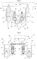
Fig. 2 is a front view of a pump mechanism according to the present invention, -
Fig. 3 is a plan view of the pump mechanism according to the present invention, -
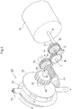
Fig. 4 is a perspective view of the pump mechanism according to the present invention, -
Fig. 5 is a perspective view of the pump mechanism according to the present invention, -
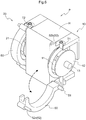
Fig. 6 is a perspective view of the pump mechanisms according to the present invention, and -
Fig. 7 is a front view of a beverage dispenser relating to a further embodiment of the present invention. - As shown in
Fig. 1 , abeverage dispenser 1 is arranged such that an openable/closable door is provided at a front face of adispenser body 2 which is a box-like component having an opened front face andoperational buttons 3 are provided in this door. - At an upper portion inside the
dispenser body 2, there is provided astorage 4 for accommodating bag-in-boxes (to be referred to simply as "containers" hereinafter) B as reservoirs for beverages such as tea, juice, etc. The container B is a structure in which a bag-like container charged with beverage under a sealed state is contained in a box-like container. Incidentally, the term "beverage" as used herein includes a concentrate liquid which is made into target beverage when diluted. - At a portion inside the
dispenser body 2 and under thestorage 4, there is provided a pump mechanism P for dispensing the beverage charged in the containers B. - In the instant embodiment, within the
storage 4 of thebeverage dispenser 1, two containers B1, B2 can be accommodated. And, the single pump mechanism P is provided for these containers B1 and B2. - Tubes T1, T2, which can be provided integrally with or separately from the containers B1, B2, have upper ends thereof connected to these containers B1, B2 and constitute inlets for beverage charged in these bottles B1, B2. Lower ends of the tubes T1, T2 constitute outlets for the beverage charged in these bottles B1, B2. Incidentally, on the lateral sides of the outlets, there are provided dilution water nozzles W1, W2 for feeding dilution water and carbonated water nozzles S1, S2 for feeding carbonated water.
- The
operational buttons 3 are disposed in correspondence with the respective containers B1, B2. In association with an operation on theoperational button 3, the pump mechanism P will be driven, so that beverage will be dispensed into a cup placed on a cup rest positioned under the outlet via this outlet formed at the lower end of the respective tube T1, T2. And, depending on need, dilution water can be fed via the dilution water nozzle W1, W2 or carbonated water can be fed via the carbonated water nozzle S1, S2. - As shown in
Fig. 2 and Fig. 3 , the pump mechanism P includes afirst tube pump 10 and asecond tube pump 20 corresponding respectively to the containers B1, B2, a single motor M for driving these first and second tube pumps 10, 20, afirst transmission mechanism 30 for transmitting power of the motor M to thefirst tube pump 10 and asecond transmission mechanism 40 for transmitting power of the motor M to thesecond tube pump 20. - The
first tube pump 10 and thesecond tube pump 20 include a plurality ofrollers first tube guide 50 and asecond tube guide 60 for guiding the beverage inside the tubes T1, T2 androtors - The plurality of
rollers rotors - A first
rotational shaft 13 of thefirst rotor 12 included in thefirst tube pump 10 and a secondrotational shaft 23 of thesecond rotor 22 included in thesecond tube pump 20 are disposed on a common axis. - The first
rotational shaft 13 and the secondrotational shaft 23 are rotatably supported via unillustrated bearings. The firstrotational shaft 13 and the secondrotational shaft 23 are provided with rotary encoders, so that via these rotary encoders, rotations of the firstrotational shaft 13 and the secondrotational shaft 23 can be determined and controlled. - The motor M is disposed between the
first tube pump 10 and thesecond tube pump 20 as seen in a plan view. This motor M is a motor with its output shaft S being rotatable in both directions, so its rotation is controlled to either the clockwise direction or the counter-clockwise direction in accordance with an operation on theoperational button 3. The firstrotational shaft 13 and the secondrotational shaft 23 are disposed to be perpendicular to the output shaft S. - The
first transmission mechanism 30 includes afirst input gear 32 and afirst transmission gear 33. Thefirst input gear 32 is mounted on afirst transmission shaft 31 parallel with the output shaft S and offset from the firstrotational shaft 13 and is meshed with an output gear G mounted on the output shaft S. Thefirst transmission gear 33 is rotatable with thefirst input gear 32 and is meshed with a first transmittedgear 14 which is non-rotatably mounted on the firstrotational shaft 13. - The
second transmission mechanism 40 includes asecond input gear 42 and a second asecond transmission gear 43. The second input gear is mounted on asecond transmission shaft 41 parallel with the output shaft S and offset from the secondrotational shaft 23 and is meshed, via a relay gear R rotatable about a relay shaft L parallel with the output shaft S, with the output gear G mounted on the output shaft S. Thesecond transmission gear 43 is rotatable with thesecond input gear 42 and is meshed with a second transmittedgear 24 which is non-rotatably mounted on the secondrotational shaft 23. - In the instant embodiment, the
first input gear 32 is directly meshed with the output gear G, whereas thesecond input gear 42 is meshed with the output gear G via the relay gear R. With this arrangement, thefirst rotor 12 and thesecond rotor 22 both can be rotated in the same direction, when thebeverage dispenser 1 is seen in its front view. - The
first transmission gear 33 and thesecond transmission gear 43 respectively is a worm mounted on thefirst transmission shaft 31 or thesecond transmission shaft 41. Whereas, the first transmittedgear 14 and the second transmittedgear 24 respectively is a worm wheel. - Incidentally, the
first input gear 32 is supported to thefirst transmission shaft 31 via a firstclutch mechanism 34. And, thesecond input gear 42 is supported to thesecond transmission shaft 41 via a secondclutch mechanism 44. Advantageously, these firstclutch mechanism 34 and secondclutch mechanism 44 can be sprag type one-way clutch or cam type one-way clutch. However, they are not limited thereto. - As shown in
Fig. 4 , the firstclutch mechanism 34 is configured to transmit rotation of the motor M in a first direction (clockwise) to thefirst input gear 32, but not to transmit rotation of the motor M in a second direction (counter-clockwise) to thefirst input gear 32. - Further, as shown in
Fig. 5 , the secondclutch mechanism 44 is configured to transmit rotation of the motor M in the second direction (counter-clockwise) to thesecond input gear 42, but not to transmit rotation of the motor M in the first direction (clockwise) to thesecond input gear 42. - Therefore, when the motor M is rotated in the first direction (clockwise), the
first input gear 32, thefirst transmission gear 33 and the first transmittedgear 14 are rotated, whereby thefirst tube pump 10 is driven, so that an amount of beverage drawn into the first tube T1 will be discharged via the outlet. In this, thesecond tube pump 20 is not driven. - Conversely, when the motor M is rotated in the second direction (counter-clockwise), the
second input gear 42, thesecond transmission gear 43 and the second transmittedgear 24 are rotated, whereby thesecond tube pump 20 is driven, so that an amount of beverage drawn into the second tube T2 will be discharged via the outlet. In this, thefirst tube pump 10 is not driven. - Next, a
first tube guide 50 and asecond tube guide 60 will be explained. Incidentally, since thesecond tube guide 60 has an identical arrangement to thefirst guide guide 50, explanation thereof will be omitted here. As shown inFig. 6 , thefirst tube guide 50 has an inner circumferential face having an arcuate shape and is configured to be capable of holding the first tube T1 for feeding beverage between this tube guide and afirst roller 11 included in thefirst rotor 12 and movable along an inner circumferential face. Thefirst tube guide 50 is pivotable about afirst pivot shaft 51 provided at its lower end and parallel with the firstrotational shaft 13 to be posture switchable between a restraining posture for squeezingly drawing the first tube T1 in cooperation with thefirst roller 11 and a releasing posture away from thefirst roller 11 for allowing attachment/detachment of the first tube T1. - Incidentally, the
first tube guide 50, at its upper end, is provided with afixing mechanism 52 for fixing the restraining posture of thefirst tube guide 50. Thisfixing mechanism 52 consists essentially of anengaging hole portion 52b provided on the side of a box body H accommodating thefirst transmission mechanism 30, thesecond transmission mechanism 40, etc. and an engagingprotrusion 52a extending through the upper end portion of thefirst tube guide 50 and having a leading end engageable with the engaginghole portion 52b. Incidentally, the engagingprotrusion 52a is urged by an unillustrated spring to the direction for engagement with the engaginghole portion 52b. - When the container B1 is to be replaced, the door of the
dispenser body 2 will be opened and then the trailing end of the engagingprotrusion 52a will be pinched by fingers and its leading end will be pulled out of the engaginghole portion 52b to release the engagement, after which thefirst tube guide 50 will be pivoted to the front side and the tube T1 connected to the container B1 will be taken out from between thefirst tube guide 50 and theroller 11 and then, the empty container B1 will be removed from thestorage 4. - Thereafter, a new container B1 will be accommodated in the
storage 4 and the tube T1 as connected to the container B1 will be passed between thefirst tube guide 50 and thefirst roller 11. Then, thefirst tube guide 50 will be closed and the lower end of the tube T1 will be cut off with a pair of scissors or the like, thus forming its outlet. Replacement of the container B2 can be carried out similarly. - As the
first tube pump 10 and thesecond tube pump 20 are disposed in such a manner that from the front side in the front view of the pump mechanism P, the tubes T1, T2 are disposed in this order among therotors first tube guide 50 and thesecond tube guide 60, replacement of the containers B1, B2 can be carried out easily via the front face of thebeverage dispenser 1. - In the foregoing embodiment, there was explained the arrangement in which rotation of the output gear G of the motor M is transmitted to the
second input gear 42 included in thesecond transmission mechanism 40 via the relay gear R. However, this relay gear R is not essential. In such case, however, it will become necessary to reverse the teeth-cutting direction of the worm which is thesecond transmission gear 43 or the direction of allowing or inhibiting power transmission by the secondclutch mechanism 44 from the currently employed direction. Further, the relay gear R may be provided on the side of thefirst transmission mechanism 30, rather than on the side of thesecond transmission mechanism 40. - In the arrangement in the foregoing embodiment, when the motor M is rotated in the first direction (clockwise), the
first tube pump 10 is driven, but thesecond tube pump 20 is not driven. Whereas, when the motor M is rotated in the second direction (counter-clockwise), thesecond tube pump 20 is driven, but thefirst tube pump 10 is not driven. However, the invention is not limited to this arrangement. By reversing the teeth-cutting direction of the worm which respectively is thefirst transmission gear 33 and thesecond transmission gear 43 or the direction of allowing or inhibiting power transmission by the firstclutch mechanism 34 and the secondclutch mechanism 44 from the currently employed direction, it is also possible to arrange such that when the motor M is rotated in the first direction (clockwise), thesecond tube pump 20 is driven but the first tube pump is not driven and when the motor M is rotated in the second direction (counter-clockwise), thefirst tube pump 10 is driven but thesecond tube pump 20 is not driven. - In the above-described embodiment, there was explained the arrangement in which the
first transmission gear 33 and thesecond transmission gear 43 are worms mounted on thefirst transmission shaft 31 or thesecond transmission shaft 41 and the first transmittedgear 14 and the second transmittedgear 24 are worm wheels. However, the invention is not limited to this arrangement. Thefirst transmission gear 33 and thesecond transmission gear 43, and the first transmittedgear 14 and the second transmittedgear 24, respectively can be spiral gears meshed with each other. - In the foregoing embodiment, there was explained the arrangement in which the first
rotational shaft 13 and thefirst transmission shaft 31 are disposed to be offset from each other and similarly, the secondrotational shaft 23 and thesecond transmission shaft 41 are disposed to be offset from each other. However, the invention is not limited to this arrangement. Alternatively, the firstrotational shaft 13 and thefirst transmission shaft 31 may disposed to intersect each other and similarly, the secondrotational shaft 23 and thesecond transmission shaft 41 may be disposed to intersect each other. In this case, advantageously, thefirst transmission gear 33 and thesecond transmission gear 43, and the first transmittedgear 14 and the second transmittedgear 24, respectively can be bevel gears meshed with each other. - In the foregoing embodiment, there was explained the arrangement in which the first
clutch mechanism 34 and the secondclutch mechanism 44 respectively is provided between thefirst input gear 32 and thefirst transmission shaft 31 or between thesecond input gear 42 and thesecond transmission shaft 41. However, the invention is not limited to this arrangement. Alternatively, the first transmittedgear 14 may be supported to the firstrotational shaft 13 via the firstclutch mechanism 34 and the second transmittedgear 24 may be supported to the secondrotational shaft 23 via the secondclutch mechanism 44. - In the foregoing embodiment, there was explained the arrangement of the
beverage dispenser 1 in which beverage is discharged respectively from the tube T1 and the tube T2 into cups set at different positions. Referring to an arrangement different fromsuch beverage dispenser 1 as shown inFig. 1 , for instance, as shown inFig. 7 , upper ends of the tubes T1, T2 of thebeverage dispenser 1 constitute inlets for beverage charged in the containers B1, B2, whereas outlets positioned at the lower ends of the tubes T1, T2 are configured to discharge beverage to a cup set at a same position. Incidentally, on the lateral sides of the two outlets, there are provided a dilution water nozzle W3 for feeding dilution water and a carbonated water nozzle S3 for feeding carbonated water. - In accordance with an operation on the
operational button 3, the pump mechanism P will be driven, so that via the two outlets at the lower ends of the tubes T1, T2, beverage will be discharged into a cut set on a cup rest provided under the two outlets. And, when needed, dilution water will be fed via the dilution water nozzle W3 or carbonated water will be fed via the carbonated water nozzle S3. - In the foregoing embodiment, there was explained a case in which the
beverage dispenser 1 is provided with a single pump mechanism P. However, the invention is not limited thereto. Alternatively, thebeverage dispenser 1 may be provided with a plurality of pump mechanisms P. - The above-described embodiments are only exemplary of the present invention. The present invention is not limited thereto. Rather, various modifications of the specific arrangements of the respective parts thereof can be made when appropriate, within the range capable of achieving the intended function/effect of the present invention.
-
- 1:
- beverage dispenser
- 10:
- first tube pump
- 10:
- tube pump
- 11:
- first roller
- 12:
- first rotor
- 13:
- first rotational shaft
- 14:
- first transmitted gear
- 20:
- second tube pump
- 20:
- tube pump
- 21:
- second roller
- 22:
- second rotor
- 23:
- second rotational shaft
- 24:
- second transmitted gear
- 30:
- first transmission mechanism
- 31:
- first transmission shaft
- 32:
- first input gear
- 33:
- first transmission gear
- 34:
- first clutch mechanism
- 40:
- second transmission mechanism
- 41:
- second transmission shaft
- 42:
- second input gear
- 43:
- second transmission gear
- 44:
- second clutch mechanism
- 50:
- first tube guide
- 60:
- second tube guide
- 100:
- beverage dispenser
- B:
- container
- B1:
- container
- B2:
- container
- G:
- output gear
- M:
- motor
- P:
- pump mechanism
- R:
- relay gear
- S:
- output shaft
- T1:
- first tube
- T2:
- second tube
Claims (5)
- A pump mechanism mounted in a beverage dispenser and configured to discharge an amount of beverage from a bag-like container charged with the beverage, the pump mechanism comprising:a first tube pump disposed in midway of a first tube connected to a first bag-like container charged with beverage;a second tube pump disposed in midway of a second tube connected to a second bag-like container charged with beverage; anda single motor for diving the first tube pump and the second tube pump;the motor being disposed with an output shaft thereof extending from a back side to a front side of the pump mechanism;the first tube pump and the second tube pump being disposed on the left and right sides of the motor on more front side than this motor as seen in a plan view in such a manner that a first rotational shaft of a first rotor included in the first tube pump and a second rotational shaft of a second rotor included in the second tube pump extend perpendicularly to the output shaft of the motor;a first transmission mechanism for transmitting power outputted from the output shaft to the first rotor;a second transmission mechanism for transmitting the power outputted from the output shaft to the second rotor;the first transmission mechanism including a first clutch mechanism configured to transmit rotation of the output shaft in a first direction to the first rotor, but not to transmit rotation of the output shaft in a second direction to the first rotor; andthe second transmission mechanism including a second clutch mechanism configured to transmit the rotation of the output shaft in the second direction to the second rotor, but not to transmit rotation of the output shaft in the first direction to the second rotor.
- The pump mechanism of claim 1, wherein:the first transmission mechanism includes a first input gear mounted on a first transmission shaft parallel with the output shaft and intersecting or offset from the first rotational shaft and configured to receive power from an output gear mounted on the output shaft and a first transmission gear rotatable with the first input gear and meshed with a first transmitted gear non-rotatably mounted on the first rotational shaft;the second transmission mechanism includes a second input gear mounted on a second transmission shaft parallel with the output shaft and intersecting or offset from the second rotational shaft and configured to receive power from the output gear and a second transmission gear rotatable with the second input gear and meshed with a second transmitted gear non-rotatably mounted on the second rotational shaft;the first input gear is supported to the first transmission shaft via the first clutch mechanism;the second input gear is supported to the second transmission shaft via the second clutch mechanism; andeither one of the first input gear and the second input gear is directly meshed with the output gear and the other thereof is meshed with the output shaft via a relay gear.
- The pump mechanism of claim 2, wherein:the first tube pump includes a first tube guide having an inner circumferential face of an arc extending along a path of a first roller included in the first rotor, the first tube guide being posture switchable between a restraining posture for squeezingly drawing the first tube by the roller moving along the inner circumferential face and a releasing posture in which the first tube guide is spaced apart from the first roller on the front side in order to allow attachment/detachment of the first tube; andthe second tube pump includes a second tube guide having an inner circumferential face of an arc extending along a path of a second roller included in the second rotor, the second tube guide being posture switchable between a restraining posture for squeezingly drawing the second tube by the roller moving along the inner circumferential face and a releasing posture in which the second tube guide is spaced apart from the second roller on the front side in order to allow attachment/detachment of the second tube.
- The pump mechanism of claim 2 or 3, wherein the first transmission gear and the second transmission gear are worms and the first transmitted gear and the second transmitted gear are worm wheels.
- A beverage dispenser comprising a pump mechanism of any one of claims 1-4.
Applications Claiming Priority (2)
| Application Number | Priority Date | Filing Date | Title |
|---|---|---|---|
| JP2016215327A JP2018071495A (en) | 2016-11-02 | 2016-11-02 | Pump mechanism and beverage dispenser |
| PCT/JP2017/039786 WO2018084258A1 (en) | 2016-11-02 | 2017-11-02 | Pump mechanism and beverage dispenser |
Publications (2)
| Publication Number | Publication Date |
|---|---|
| EP3536957A1 true EP3536957A1 (en) | 2019-09-11 |
| EP3536957A4 EP3536957A4 (en) | 2020-07-01 |
Family
ID=62076027
Family Applications (1)
| Application Number | Title | Priority Date | Filing Date |
|---|---|---|---|
| EP17867678.9A Withdrawn EP3536957A4 (en) | 2016-11-02 | 2017-11-02 | PUMP MECHANISM AND BEVERAGE DISPENSER |
Country Status (7)
| Country | Link |
|---|---|
| US (1) | US20200062573A1 (en) |
| EP (1) | EP3536957A4 (en) |
| JP (1) | JP2018071495A (en) |
| KR (1) | KR20190073493A (en) |
| CN (1) | CN110431309A (en) |
| TW (1) | TW201819765A (en) |
| WO (1) | WO2018084258A1 (en) |
Families Citing this family (5)
| Publication number | Priority date | Publication date | Assignee | Title |
|---|---|---|---|---|
| JP7184201B2 (en) * | 2019-07-26 | 2022-12-06 | 富士電機株式会社 | beverage dispenser |
| CN113251178B (en) * | 2021-04-28 | 2022-12-09 | 深圳市西啡科技有限公司 | Waterway switching structure |
| CN113404673B (en) * | 2021-07-16 | 2022-09-02 | 牟伟 | Duplex diaphragm pump |
| LU103064B1 (en) | 2023-01-20 | 2024-07-22 | Stratec Se | Peristaltic pump |
| EP4488520B1 (en) | 2023-07-07 | 2026-02-04 | Fas Medic S.A. | Fluid delivery apparatus |
Family Cites Families (11)
| Publication number | Priority date | Publication date | Assignee | Title |
|---|---|---|---|---|
| US4443333A (en) * | 1981-09-24 | 1984-04-17 | Mahurkar Sakharam D | Portable dialysis system and pump therefor |
| DE3511572A1 (en) * | 1985-03-29 | 1986-10-09 | Abel Pumpen GmbH & Co KG, 2059 Büchen | Hose pump assembly, especially for feeding filter presses with industrial sludges or sewage sludges |
| JPH1130186A (en) * | 1997-07-10 | 1999-02-02 | Fuji Electric Co Ltd | Tube type pump device for BIB type beverage dispenser |
| US7651010B2 (en) * | 2005-09-23 | 2010-01-26 | Nestec S.A. | Food dispenser with pump for dispensing from a plurality of sources |
| WO2008139460A2 (en) * | 2007-05-11 | 2008-11-20 | Medingo Ltd. | A modular skin-patch type medical fluid delivery device |
| JP5097622B2 (en) * | 2007-06-08 | 2012-12-12 | 株式会社アクアテック | Flat tube pump |
| US8292604B2 (en) * | 2009-05-01 | 2012-10-23 | Xerox Corporation | Peristaltic pump |
| CN202746141U (en) * | 2012-09-11 | 2013-02-20 | 苏州威士德电子有限公司 | Twin peristalsis transfer pump |
| JP2014077418A (en) * | 2012-10-12 | 2014-05-01 | Fuji Electric Co Ltd | Liquid supply pump |
| WO2016148220A1 (en) * | 2015-03-19 | 2016-09-22 | サントリーホールディングス株式会社 | Container |
| DE102015207342B4 (en) * | 2015-04-22 | 2021-09-23 | BSH Hausgeräte GmbH | Laundry care device with a dosing system |
-
2016
- 2016-11-02 JP JP2016215327A patent/JP2018071495A/en active Pending
-
2017
- 2017-11-02 TW TW106137913A patent/TW201819765A/en unknown
- 2017-11-02 KR KR1020197015136A patent/KR20190073493A/en not_active Ceased
- 2017-11-02 WO PCT/JP2017/039786 patent/WO2018084258A1/en not_active Ceased
- 2017-11-02 US US16/346,663 patent/US20200062573A1/en not_active Abandoned
- 2017-11-02 EP EP17867678.9A patent/EP3536957A4/en not_active Withdrawn
- 2017-11-02 CN CN201780067838.4A patent/CN110431309A/en active Pending
Also Published As
| Publication number | Publication date |
|---|---|
| US20200062573A1 (en) | 2020-02-27 |
| EP3536957A4 (en) | 2020-07-01 |
| TW201819765A (en) | 2018-06-01 |
| CN110431309A (en) | 2019-11-08 |
| WO2018084258A1 (en) | 2018-05-11 |
| JP2018071495A (en) | 2018-05-10 |
| KR20190073493A (en) | 2019-06-26 |
Similar Documents
| Publication | Publication Date | Title |
|---|---|---|
| US20200062573A1 (en) | Pump mechanism and beverage dispenser | |
| US5875930A (en) | United type-beverage dispenser | |
| TWI678325B (en) | Pack | |
| JP6392383B2 (en) | Beverage cartridge | |
| CN105982547A (en) | Liquid dispenser | |
| US20120160927A1 (en) | Water fountain | |
| US20130043274A1 (en) | Package for storing and dosing a fluid and dispenser for docking the package | |
| US5088625A (en) | Drive mechanism for the measured dispensing of liquids out of a storage container | |
| CN105982554A (en) | A container | |
| ES2698125T3 (en) | Beverage dispensing system | |
| US10865097B2 (en) | Chemical product dispensing using a fluid drive and return home interface | |
| CN112323393B (en) | Detergent dispensing device and washing equipment | |
| JP2014077418A (en) | Liquid supply pump | |
| HK40010050A (en) | Pump mechanism and beverage dispenser | |
| JPH1130186A (en) | Tube type pump device for BIB type beverage dispenser | |
| KR101895666B1 (en) | Straw Attachment Device of the Rectangular Drinking Container and Method | |
| JP7265247B2 (en) | film feeder | |
| EP0866429A1 (en) | Apparatus for feeding sheets from a sheet store | |
| CN208631770U (en) | It is a kind of for ticket terminal paper transport device and for ticket terminal | |
| JP4802374B2 (en) | Cap vending machine for cup type vending machine | |
| KR100283573B1 (en) | Discharge Roller One-way Rotation Switching Device of Image Forming Device | |
| KR100746919B1 (en) | Specification table recovery reinforcement device of cash dispenser | |
| KR0132062B1 (en) | Automatic vending machine | |
| CN103922158A (en) | Automatic material storage tank | |
| US215894A (en) | Improvement in straw-cutters |
Legal Events
| Date | Code | Title | Description |
|---|---|---|---|
| STAA | Information on the status of an ep patent application or granted ep patent |
Free format text: STATUS: THE INTERNATIONAL PUBLICATION HAS BEEN MADE |
|
| PUAI | Public reference made under article 153(3) epc to a published international application that has entered the european phase |
Free format text: ORIGINAL CODE: 0009012 |
|
| STAA | Information on the status of an ep patent application or granted ep patent |
Free format text: STATUS: REQUEST FOR EXAMINATION WAS MADE |
|
| 17P | Request for examination filed |
Effective date: 20190602 |
|
| AK | Designated contracting states |
Kind code of ref document: A1 Designated state(s): AL AT BE BG CH CY CZ DE DK EE ES FI FR GB GR HR HU IE IS IT LI LT LU LV MC MK MT NL NO PL PT RO RS SE SI SK SM TR |
|
| AX | Request for extension of the european patent |
Extension state: BA ME |
|
| DAV | Request for validation of the european patent (deleted) | ||
| DAX | Request for extension of the european patent (deleted) | ||
| A4 | Supplementary search report drawn up and despatched |
Effective date: 20200529 |
|
| RIC1 | Information provided on ipc code assigned before grant |
Ipc: F04B 9/04 20060101ALI20200525BHEP Ipc: F04C 5/00 20060101AFI20200525BHEP Ipc: B67D 1/10 20060101ALI20200525BHEP Ipc: F16H 1/20 20060101ALI20200525BHEP Ipc: F04B 43/12 20060101ALI20200525BHEP Ipc: F04B 23/06 20060101ALI20200525BHEP Ipc: F16H 1/16 20060101ALI20200525BHEP Ipc: F16H 1/06 20060101ALI20200525BHEP |
|
| STAA | Information on the status of an ep patent application or granted ep patent |
Free format text: STATUS: THE APPLICATION IS DEEMED TO BE WITHDRAWN |
|
| 18D | Application deemed to be withdrawn |
Effective date: 20210112 |