EP3536915A1 - Thermal energy recovery device and startup operation method for same - Google Patents
Thermal energy recovery device and startup operation method for same Download PDFInfo
- Publication number
- EP3536915A1 EP3536915A1 EP17875253.1A EP17875253A EP3536915A1 EP 3536915 A1 EP3536915 A1 EP 3536915A1 EP 17875253 A EP17875253 A EP 17875253A EP 3536915 A1 EP3536915 A1 EP 3536915A1
- Authority
- EP
- European Patent Office
- Prior art keywords
- working fluid
- temperature
- flow path
- heating
- circulation flow
- Prior art date
- Legal status (The legal status is an assumption and is not a legal conclusion. Google has not performed a legal analysis and makes no representation as to the accuracy of the status listed.)
- Withdrawn
Links
- 238000011084 recovery Methods 0.000 title claims abstract description 62
- 238000000034 method Methods 0.000 title claims description 13
- 239000012530 fluid Substances 0.000 claims abstract description 216
- 238000010438 heat treatment Methods 0.000 claims abstract description 86
- 238000001704 evaporation Methods 0.000 claims abstract description 67
- 230000001629 suppression Effects 0.000 claims abstract description 19
- 230000008020 evaporation Effects 0.000 claims description 57
- 239000002826 coolant Substances 0.000 claims description 13
- 238000001816 cooling Methods 0.000 claims description 8
- 239000007788 liquid Substances 0.000 claims description 7
- XLYOFNOQVPJJNP-UHFFFAOYSA-N water Substances O XLYOFNOQVPJJNP-UHFFFAOYSA-N 0.000 abstract description 72
- 230000008646 thermal stress Effects 0.000 description 14
- 230000007423 decrease Effects 0.000 description 6
- 238000002955 isolation Methods 0.000 description 5
- 239000012071 phase Substances 0.000 description 5
- 230000007704 transition Effects 0.000 description 5
- 238000001514 detection method Methods 0.000 description 4
- 238000010586 diagram Methods 0.000 description 4
- 238000010248 power generation Methods 0.000 description 3
- 238000005219 brazing Methods 0.000 description 2
- 239000000470 constituent Substances 0.000 description 1
- 239000000498 cooling water Substances 0.000 description 1
- 230000007797 corrosion Effects 0.000 description 1
- 238000005260 corrosion Methods 0.000 description 1
- 238000006073 displacement reaction Methods 0.000 description 1
- 230000000694 effects Effects 0.000 description 1
- 239000007791 liquid phase Substances 0.000 description 1
- 230000004048 modification Effects 0.000 description 1
- 238000012986 modification Methods 0.000 description 1
- 230000035882 stress Effects 0.000 description 1
- 238000011144 upstream manufacturing Methods 0.000 description 1
Images


Classifications
-
- F—MECHANICAL ENGINEERING; LIGHTING; HEATING; WEAPONS; BLASTING
- F01—MACHINES OR ENGINES IN GENERAL; ENGINE PLANTS IN GENERAL; STEAM ENGINES
- F01K—STEAM ENGINE PLANTS; STEAM ACCUMULATORS; ENGINE PLANTS NOT OTHERWISE PROVIDED FOR; ENGINES USING SPECIAL WORKING FLUIDS OR CYCLES
- F01K25/00—Plants or engines characterised by use of special working fluids, not otherwise provided for; Plants operating in closed cycles and not otherwise provided for
- F01K25/08—Plants or engines characterised by use of special working fluids, not otherwise provided for; Plants operating in closed cycles and not otherwise provided for using special vapours
- F01K25/10—Plants or engines characterised by use of special working fluids, not otherwise provided for; Plants operating in closed cycles and not otherwise provided for using special vapours the vapours being cold, e.g. ammonia, carbon dioxide, ether
-
- F—MECHANICAL ENGINEERING; LIGHTING; HEATING; WEAPONS; BLASTING
- F01—MACHINES OR ENGINES IN GENERAL; ENGINE PLANTS IN GENERAL; STEAM ENGINES
- F01K—STEAM ENGINE PLANTS; STEAM ACCUMULATORS; ENGINE PLANTS NOT OTHERWISE PROVIDED FOR; ENGINES USING SPECIAL WORKING FLUIDS OR CYCLES
- F01K13/00—General layout or general methods of operation of complete plants
- F01K13/02—Controlling, e.g. stopping or starting
-
- F—MECHANICAL ENGINEERING; LIGHTING; HEATING; WEAPONS; BLASTING
- F01—MACHINES OR ENGINES IN GENERAL; ENGINE PLANTS IN GENERAL; STEAM ENGINES
- F01D—NON-POSITIVE DISPLACEMENT MACHINES OR ENGINES, e.g. STEAM TURBINES
- F01D17/00—Regulating or controlling by varying flow
- F01D17/10—Final actuators
- F01D17/12—Final actuators arranged in stator parts
- F01D17/14—Final actuators arranged in stator parts varying effective cross-sectional area of nozzles or guide conduits
- F01D17/141—Final actuators arranged in stator parts varying effective cross-sectional area of nozzles or guide conduits by means of shiftable members or valves obturating part of the flow path
- F01D17/145—Final actuators arranged in stator parts varying effective cross-sectional area of nozzles or guide conduits by means of shiftable members or valves obturating part of the flow path by means of valves, e.g. for steam turbines
-
- F—MECHANICAL ENGINEERING; LIGHTING; HEATING; WEAPONS; BLASTING
- F22—STEAM GENERATION
- F22B—METHODS OF STEAM GENERATION; STEAM BOILERS
- F22B1/00—Methods of steam generation characterised by form of heating method
- F22B1/02—Methods of steam generation characterised by form of heating method by exploitation of the heat content of hot heat carriers
- F22B1/16—Methods of steam generation characterised by form of heating method by exploitation of the heat content of hot heat carriers the heat carrier being hot liquid or hot vapour, e.g. waste liquid, waste vapour
-
- F—MECHANICAL ENGINEERING; LIGHTING; HEATING; WEAPONS; BLASTING
- F22—STEAM GENERATION
- F22B—METHODS OF STEAM GENERATION; STEAM BOILERS
- F22B1/00—Methods of steam generation characterised by form of heating method
- F22B1/02—Methods of steam generation characterised by form of heating method by exploitation of the heat content of hot heat carriers
- F22B1/18—Methods of steam generation characterised by form of heating method by exploitation of the heat content of hot heat carriers the heat carrier being a hot gas, e.g. waste gas such as exhaust gas of internal-combustion engines
-
- F—MECHANICAL ENGINEERING; LIGHTING; HEATING; WEAPONS; BLASTING
- F22—STEAM GENERATION
- F22B—METHODS OF STEAM GENERATION; STEAM BOILERS
- F22B35/00—Control systems for steam boilers
- F22B35/001—Controlling by flue-gas dampers
-
- F—MECHANICAL ENGINEERING; LIGHTING; HEATING; WEAPONS; BLASTING
- F22—STEAM GENERATION
- F22D—PREHEATING, OR ACCUMULATING PREHEATED, FEED-WATER FOR STEAM GENERATION; FEED-WATER SUPPLY FOR STEAM GENERATION; CONTROLLING WATER LEVEL FOR STEAM GENERATION; AUXILIARY DEVICES FOR PROMOTING WATER CIRCULATION WITHIN STEAM BOILERS
- F22D1/00—Feed-water heaters, i.e. economisers or like preheaters
Definitions
- the present invention relates to a thermal energy recovery device and a startup operation method for the same.
- patent literature 1 discloses a power generation device (thermal energy recovery device) with an evaporator, a preheater, an expander, a power generator, a condenser, a working fluid pump and a circulation flow path.
- the evaporator heats a working fluid with a heating medium supplied from an external heat source.
- the preheater heats the working fluid before flowing into the evaporator with the heating medium flowing out from the evaporator.
- the expander expands the working fluid flowing out from the evaporator.
- the power generator is connected to the expander.
- the condenser condenses the working fluid flowing out from the expander.
- the working fluid pump feeds the working fluid condensed in the condenser to the preheater.
- the circulation flow path connects the preheater, the evaporator, the expander, the condenser and the pump.
- the temperature of the evaporator suddenly increases at the time of starting the operation of this recovery device, whereby a thermal stress generated in the evaporator may suddenly increase.
- the temperature of the evaporator is relatively low, whereas thermal energy of the heating medium such as steam is very large.
- the high-temperature heating medium flows into the evaporator at the time of starting the operation, the temperature of the evaporator may suddenly increase.
- Patent Literature 1 Japanese Unexamined Patent Publication No. 2014-47632
- An object of the present invention is to provide a thermal energy recovery device capable of suppressing a sudden increase of a thermal stress generated in an evaporator at the time of starting an operation and a startup operation method for the same.
- a thermal energy recovery device includes a working fluid circulation flow path for circulating a working fluid, a thermal fluid circulation flow path for circulating a pressurized heating fluid in a liquid state, an evaporation unit for evaporating the working fluid flowing in the working fluid circulation flow path by heat of the heating fluid flowing in the thermal fluid circulation flow path, and a control unit for controlling a startup operation of the thermal energy recovery device.
- the control unit executes a suppression control for suppressing a temperature difference between the heating fluid and the working fluid in the evaporation unit in the startup operation.
- a startup operation method for thermal energy recovery device is a startup operation method for thermal recovery device with an evaporation unit for evaporating a working fluid flowing in a working fluid circulation flow path by heat of a heating fluid flowing in a thermal fluid circulation flow path, wherein a suppression control for suppressing a temperature of the working fluid in the evaporation unit is executed in a startup operation of the thermal energy recovery device.
- thermal energy recovery device according to a first embodiment of the present invention is described with reference to the drawings.
- the thermal energy recovery device 1 includes a working fluid circulation flow path for circulating a working fluid while being accompanied by a phase change (hereinafter, merely referred to as a "circulation flow path") 22, a thermal fluid circulation flow path 30 for circulating hot water serving as a pressurized heating fluid in a liquid state, and a control unit 50.
- a heater 32 is provided in the thermal fluid circulation flow path 30.
- This heater 32 includes a heating medium flow path 32a in which a heating medium (high-temperature gas such as corrosive gas) in a gas phase flows and a thermal fluid flow path 32b in which hot water flows.
- the heating medium in the heating medium flow path 32a and the hot water in the thermal fluid flow path 32b exchange heat in the heater 32. In this way, the hot water is heated.
- the thermal energy recovery device 1 recovers thermal energy of the heating medium. In the recovery device 1, this thermal energy of the heating medium is temporarily recovered in the hot water of the thermal fluid circulation flow path 30.
- the thermal fluid circulation flow path 30 is interposed between a pipe 34 in which the heating medium flows and the circulation flow path 22 in which the working fluid is circulated, the heating medium does not flow into later-described evaporator 10 and preheater 12 provided in the circulation flow path 22. Thus, even if the heating medium is corrosive gas, the corrosion of the evaporator 10 and the preheater 12 can be prevented.
- the heating medium flow path 32a is connected to a heating pipe 35 branched from the pipe 34 in which the heating medium flows.
- a flow rate of the heating medium flowing into the heater 32 can be adjusted by changing an opening of a flow rate control value Va1 provided in the heating pipe 35.
- the flow rate control valve Va1 may be arranged upstream of the heater 32 in the heating pipe 35 or may be arranged downstream of the heater 32.
- the evaporator 10, the preheater 12, an energy recovery unit 13, a condenser 18 and a pump 20 are provided in the circulation flow path 22.
- the evaporator 10 includes a first flow path 10a in which the working fluid flows and a second flow path 10b in which the hot water flows.
- the evaporator 10 performs heat exchange between the hot water in the thermal fluid circulation flow path 30 and the working fluid (HFC245fa or the like) in the circulation flow path 22. In this way, the working fluid evaporates.
- a brazing plate type heat exchanger is used as the evaporator 10.
- a so-called shell-and-tube type heat exchanger may be used as the evaporator 10.
- the preheater 12 is arranged between the evaporator 10 and the pump 20 in the circulation flow path 22.
- the preheater 12 includes a first flow path 12a in which the working fluid flows and a second flow path 12b in which the hot water flows.
- the preheater 12 performs heat exchange between the hot water flowing out from the evaporator 10 and the working fluid before flowing into the evaporator 10. In this way, the working fluid is heated.
- a brazing plate type heat exchanger is used also as the preheater 12.
- a so-called shell-and-tube heat exchanger may be used as the preheater 12 as in the case of the evaporator 10.
- an evaporation unit for evaporating the working fluid includes the evaporator 10 and the preheater 12 provided separately from the evaporator 10.
- the evaporator 10 functioning as the evaporation unit may be provided, whereas the preheater may be omitted.
- the energy recovery unit 13 includes an expander 14 and a power recovery device 16.
- the expander 14 is provided in a part of the circulation flow path 22 downstream of the evaporator 10.
- the preheater 12, the evaporator 10, the expander 14, the condenser 18 and the pump 20 are connected to the circulation flow path 22 in this order.
- the expander 14 expands the working fluid in a gas phase flowing out from the evaporator 10.
- a positive displacement screw expander including a rotor to be rotationally driven by expansion energy of the working fluid in a gas phase flowing out from the evaporator 10 is used as the expander 14.
- the expander 14 includes a pair of male and female screw rotors.
- the power recovery device 16 is connected to the expander 14.
- a power generator is used as the power recovery device 16.
- This power recovery device 16 includes a rotary shaft connected to one of the pair of screw rotors of the expander 14.
- the power recovery device 16 generates power as the rotary shaft rotates according to the rotation of the screw rotor.
- a compressor or the like may be used as the power recovery device 16.
- An isolation valve V-1 is provided in a part of the circulation flow path 22 between the evaporator 10 and the expander 14. Further, a bypass flow path 24 bypassing the isolation valve V-1 and the expander 14 is provided in the circulation flow path 22. An on-off valve V-2 is provided in the bypass flow path 24.
- the condenser 18 is provided in a part of the circulation flow path 22 downstream of the expander 14.
- the condenser 18 condenses (liquefies) the working fluid flowing out from the expander 14 by cooling the working fluid with a cooling medium (cooling water or the like) supplied from outside.
- the cooling medium is supplied through a cooling medium flow path 37, for example, from a cooling tower connected to the cooling medium flow path 37.
- the pump 20 is provided in a part of the circulation flow path 22 downstream of the condenser 18 (part between the condenser 18 and the preheater 12).
- the pump 20 pressurizes the working fluid in a liquid phase to a predetermined pressure and feeds the pressurized working fluid to the preheater 12.
- a centrifugal pump including an impeller as a rotor, a gear pump including a rotor composed of a pair of gears, a screw pump, a trochoid pump or the like is used as the pump 20.
- the heating fluid is sealed in a pressurized state in the thermal fluid circulation flow path 30.
- the hot water is sealed in a pressurized state in the thermal fluid circulation flow path 30.
- the evaporator 10, the preheater 12, a buffer tank 38, a fluid pump 40 and the heater 32 are arranged in this order in the thermal fluid circulation flow path 30.
- the hot water successively flows through the evaporator 10, the preheater 12, the buffer tank 38, the fluid pump 40 and the heater 32.
- the buffer tank 38 is provided on a suction side of the fluid pump 40. By providing the buffer tank 38, a predetermined pressure (head pressure) can be applied to the suction side of the fluid pump 40.
- the thermal energy recovery device 1 is provided with an inlet-side working fluid temperature sensor Tr1, an outlet-side working fluid temperature sensor Tr2, an inlet-side hot water temperature sensor Tw1 and an outlet-side hot water temperature sensor Tw2.
- the inlet-side working fluid temperature sensor Tr1 detects a temperature of the working fluid on an inlet side of the evaporation unit, i.e. the preheater 12 and outputs a signal indicative of a detection value.
- the outlet-side working fluid temperature sensor Tr2 detects a temperature of the working fluid on an outlet side of the evaporation unit, i.e. the evaporator 10 and outputs a signal indicative of a detection value.
- the inlet-side hot water temperature sensor Tw1 detects a temperature of the hot water on an inlet side of the evaporation unit, i.e. the evaporator 10 and outputs a signal indicative of a detection value.
- the outlet-side hot water temperature sensor Tw2 detects a temperature of the hot water on an outlet side of the evaporation unit, i.e. the preheater 12 and outputs a signal indicative of a detection value.
- the signals output from these sensors Tr1, Tr2, Tw1 and Tw2 are input to the control unit 50.
- the control unit 50 executes a suppression control for suppressing a temperature difference between the hot water and the working fluid in the evaporator 10 and the preheater 12 during a startup operation of the thermal energy recovery device 1.
- the temperature of the working fluid increases from a temperature tr1 on the inlet side of the preheater 12 to a temperature tr3 by being heated by the hot water in the preheater 12 and the evaporator 10. Then, the working fluid evaporated in the evaporator 10 is further heated in the evaporator 10 to reach a temperature tr2.
- the temperature of the hot water gradually decreases from a temperature tw1 on the inlet side of the evaporator 10 and reaches a temperature tw2 on the outlet side of the preheater 12. Since the working fluid undergoes a phase change in the evaporator 10, a temperature change amount is small. In contrast, a temperature change amount of the working fluid is large in the preheater 12. Thus, a temperature difference ⁇ t between the temperature tw2 of the hot water on the outlet side of the preheater 12 and the temperature tr1 of the working fluid on the inlet side of the preheater 12 increases. Particularly, since the temperature of the working fluid is low in some cases during the startup operation, the temperature difference ⁇ t tends to increase and a thermal stress generated in the preheater 12 possibly becomes problematic.
- control unit 50 executes the suppression control for suppressing the temperature difference between the hot water and the working fluid in the evaporator 10 and the preheater 12 during the startup operation.
- Step ST1 a control operation of the startup operation is described with reference to FIG. 3 .
- an operator first confirms that the flow rate control valve Va1 is closed, the isolation valve V-1 is closed and the on-off valve V-2 in the bypass flow path 24 is open (Step ST1). Then, the operator operates an unillustrated start button. In this way, the pump 20 and the fluid pump 40 start operating (Step ST2). Further, the operation of the cooling tower is started, whereby the cooling medium is supplied to the condenser 18 through the cooling medium flow path 37 (Step ST3).
- the control unit 50 controls to slightly open the flow rate control valve Va1 (Step ST4). At this time, the opening is set at a value set in advance such as ⁇ %.
- the control unit 50 controls to gradually increase the opening of the flow rate control valve Va1 (Step ST5). In this way, the temperature of the hot water gradually increases. At this time, the temperature tw1 of the hot water on the inlet side of the evaporator 10 is monitored by the inlet-side hot water temperature sensor Tw1.
- the control unit 50 gradually increases the opening of the flow rate control valve Va1 until the temperature reaches an operation start temperature (e.g. 90°C) set in advance.
- the operation start temperature is not limited to 90°C and, for example, a range of about ⁇ 5°C is allowed.
- the control unit 50 opens the isolation valve V-1 and closes the on-off valve V-2 in the bypass flow path 24. In this way, the expander 14 is driven to start power recovery by the power recovery device 16 (Step ST6). Then, it is confirmed whether or not the operation (power generation) has been continuously stably performed for a given time (Step ST7).
- the control unit 50 controls to gradually increases the opening of the flow rate control valve Va1 with the temperatures monitored by the respective temperature sensors Tr1, Tr2, Tw1 and Tw2 (Step ST8).
- a rate of increasing the opening of the flow rate control valve Va1 is so set that a temperature increase rate ⁇ T (C°/min) of the temperature tw1 of the hot water on the inlet side of the evaporator 10 is larger than a temperature increase rate when the temperature is below the operation start temperature.
- Step ST8 the temperature tw1 of the hot water on the inlet side of the evaporator 10 is monitored and, if the temperature Tw1 of the hot water is below a temperature set in advance, the control unit 50 gradually increases the opening of the flow rate control valve Va1 as described above. If the temperature Tw1 of the hot water is equal to or higher than the temperature set in advance, the temperature difference ⁇ t between the temperature tw2 of the hot water on the outlet side of the preheater 12 and the temperature tr1 of the working fluid on the inlet side of the preheater 12 is also monitored.
- the control unit 50 executes the suppression control to gradually increase the opening of the flow rate control valve Va1 in such a range where the temperature difference ⁇ t does not exceed a value set in advance.
- the temperature tw1 of the hot water on the inlet side of the evaporator 10 gradually increases and the temperature tw2 of the hot water on the outlet side of the preheater 12 also gradually increases.
- the temperature difference ⁇ t between the temperature tw2 and the temperature tr1 is suppressed to be equal to or lower than a predetermined temperature and does not become excessive. Specifically, an input heat quantity increase rate from the hot water in the evaporator 10 and the preheater 12 is suppressed.
- a rotation speed of the fluid pump 40 may also be adjusted in association with an opening adjustment of the flow rate control valve Va1. Specifically, the rotation speed of the fluid pump 40 may be adjusted to further finely adjust the temperature by the flow rate control valve Va1.
- the control unit 50 judges whether or not the temperature tw1 of the hot water on the inlet side of the evaporator 10 has reached an operating temperature (e.g. 130°C) set in advance (Step ST9) and the startup operation transitions to a normal operation by an automatic operation when the temperature Tw1 reaches the operating temperature (Step ST10).
- an operating temperature e.g. 130°C
- the temperature tw1 of the hot water on the inlet side of the evaporator 10 is, for example, about 130°C
- the temperature of the hot water on the outlet side of the evaporator 10 is, for example, about 115°C.
- the temperature tw2 of the hot water on the outlet side of the preheater 12 is, for example, about 100°C.
- the temperature of the working fluid on the inlet side of the preheater 12 is, for example, about 20°C at the start of the operation, but reaches, for example, about 40°C during the normal operation.
- the temperature of the working fluid on the outlet side of the evaporator 10 is, for example, about 120°C.
- FIG. 4 shows a stop flow during the automatic operation.
- the control unit 50 closes the isolation valve V-1 and opens the on-off valve V-2 in the bypass flow path 24 (Step ST22). In this way, the working fluid bypasses the expander 14, wherefore power generation is stopped. Then, the flow rate control valve Va1 is closed (Step ST23). Since the temperature of the hot water circulating in the thermal fluid circulation flow path 30 decreases in this way, the input heat quantities to the evaporator 10 and the preheater 12 decrease. Then, the pump 20 and a hot water pump are stopped (Step ST24). At this time, the operation of the cooling tower is maintained (Step ST25).
- heat exchange is performed between the hot water introduced from the thermal fluid circulation flow path 30 and the working fluid introduced from the circulation flow path 22 in the evaporator 10 and the preheater 12. Since the pressurized hot water in a liquid state flows into the evaporator 10 and the preheater 12, thermal energy introduced to the evaporator 10 and the preheater 12 is large. Thus, in the startup operation in which the temperature of the working fluid is relatively low, the suppression control is executed to suppress the temperature difference between the hot water and the working fluid in the evaporator 10 and the preheater 12. Therefore, it can be suppressed that large thermal stresses are generated in the evaporator 10 and the preheater 12 during the startup operation.
- the input heat quantities in the evaporator 10 and the preheater 12 are suppressed such that the temperature difference ⁇ t between the temperature tw2 of the hot water on the outlet side of the preheater 12 and the temperature tr1 of the working fluid on the inlet side of the preheater 12 is equal to or lower than the predetermined temperature.
- the thermal stresses in the evaporator 10 and the preheater 12 become excessive at the start of the operation.
- the temperature difference between the temperature tw2 of the hot water on the outlet side and the temperature tr1 of the working fluid on the inlet side is largest in the preheater 12.
- control unit 50 adjusts the opening of the flow rate control valve Va1 in the startup operation, whereby the temperature difference ⁇ t between the temperature tw2 of the hot water on the outlet side and the temperature tr1 of the working fluid on the inlet side is maintained to be equal to or lower than the predetermined temperature.
- the control unit 50 adjusts the opening of the flow rate control valve Va1 in the startup operation, whereby the temperature difference ⁇ t between the temperature tw2 of the hot water on the outlet side and the temperature tr1 of the working fluid on the inlet side is maintained to be equal to or lower than the predetermined temperature.
- the suppression control is executed to control the temperature difference ⁇ t between the hot water and the working fluid in the startup operation.
- FIG. 6 shows a second embodiment of the present invention. Note that the same constituent elements as in the first embodiment are denoted by the same reference signs and the detailed description thereof is omitted here.
- a cooler 53 is provided in a thermal fluid circulation flow path 30 and a temperature difference ⁇ t between a temperature tw2 of hot water on an outlet side of a preheater 12 and a temperature tr1 of a working fluid on an inlet side of the preheater 12 is reduced by operating the cooler 53.
- the cooler 53 is for reducing the temperature of the hot water through heat exchange between a cooling medium (air, water or the like) and the hot water. If air is used as the cooling medium, a fan 54 for generating an air flow is provided. By driving the fan 54, the cooler 53 operates. In this way, the temperature difference ⁇ t between the temperature tw2 of the hot water on the outlet side of the preheater 12 and the temperature tr1 of the working fluid on the inlet side is controlled to or below a predetermined temperature. Note that if water is used as the cooling medium, an unillustrated pump is provided and the cooler 53 operates by driving the pump.
- a cooling medium air, water or the like
- a temperature tw4 of the hot water on an inlet side of the preheater 12 becomes lower than a temperature tw3 of the hot water on an outlet side of the evaporator 10 as shown in FIG. 7 by operating the cooler 53.
- the temperature difference ⁇ t between the temperature tw2 of the hot water on the outlet side of the preheater 12 and the temperature tr1 of the working fluid on the inlet side of the preheater 12 is suppressed to be equal to or lower than the predetermined temperature.
- the temperature of the hot water exhibits a temperature transition shown in FIG. 2 in a state where the cooler 53 is not operated.
- Step ST31 whether or not the temperature difference ⁇ t between the temperature tw2 of the hot water on the outlet side of the preheater 12 and the temperature tr1 of the working fluid on the inlet side of the preheater 12 is equal to or lower than the temperature set in advance during the normal operation is monitored by the control unit 50 (Step ST31) as shown in FIG. 8 . If the temperature difference ⁇ t is judged to have exceeded the temperature set in advance, the control unit 50 operates the cooler 53 (Step ST32).
- the control unit 50 stops the cooler 53 (Step ST54).
- the control unit 50 operates the cooler 53 if the temperature difference ⁇ t between the hot water and the working fluid exceeds the predetermined temperature. In this way, the temperature of the hot water flowing in the thermal fluid circulation flow path 30 decreases. Thus, the temperature difference ⁇ t between the hot water and the working fluid in the preheater 12 can be reduced.
- a regenerator 58 is provided between a pump 20 and the preheater 12 in a circulation flow path 22. This regenerator 58 heats the working fluid flowing from the pump 20 toward the preheater 12 by the working fluid discharged from an expander 14 and flowing toward a condenser 18. In this way, the temperature difference ⁇ t in the preheater 12 can be reduced by increasing the temperature of the working fluid before flowing into the preheater 12. Specifically, as shown in FIG.
Landscapes
- Engineering & Computer Science (AREA)
- Mechanical Engineering (AREA)
- General Engineering & Computer Science (AREA)
- Chemical & Material Sciences (AREA)
- Combustion & Propulsion (AREA)
- Physics & Mathematics (AREA)
- Thermal Sciences (AREA)
- Life Sciences & Earth Sciences (AREA)
- Sustainable Development (AREA)
- Sustainable Energy (AREA)
- Engine Equipment That Uses Special Cycles (AREA)
- Heat-Pump Type And Storage Water Heaters (AREA)
Abstract
Description
- The present invention relates to a thermal energy recovery device and a startup operation method for the same.
- Conventionally, a thermal energy recovery device is known which recovers power from a heating medium such as exhaust gas discharged from various facilities such as factories. For example,
patent literature 1 discloses a power generation device (thermal energy recovery device) with an evaporator, a preheater, an expander, a power generator, a condenser, a working fluid pump and a circulation flow path. The evaporator heats a working fluid with a heating medium supplied from an external heat source. The preheater heats the working fluid before flowing into the evaporator with the heating medium flowing out from the evaporator. The expander expands the working fluid flowing out from the evaporator. The power generator is connected to the expander. The condenser condenses the working fluid flowing out from the expander. The working fluid pump feeds the working fluid condensed in the condenser to the preheater. The circulation flow path connects the preheater, the evaporator, the expander, the condenser and the pump. - In the thermal energy recovery device described in the
above literature 1, if the high-temperature heating medium is supplied to the evaporator, the temperature of the evaporator suddenly increases at the time of starting the operation of this recovery device, whereby a thermal stress generated in the evaporator may suddenly increase. Specifically, before the operation of the recovery device is started, the temperature of the evaporator is relatively low, whereas thermal energy of the heating medium such as steam is very large. Thus, if the high-temperature heating medium flows into the evaporator at the time of starting the operation, the temperature of the evaporator may suddenly increase. - Patent Literature 1: Japanese Unexamined Patent Publication No.
2014-47632 - An object of the present invention is to provide a thermal energy recovery device capable of suppressing a sudden increase of a thermal stress generated in an evaporator at the time of starting an operation and a startup operation method for the same.
- To achieve the above object, a thermal energy recovery device according to one aspect of the present invention includes a working fluid circulation flow path for circulating a working fluid, a thermal fluid circulation flow path for circulating a pressurized heating fluid in a liquid state, an evaporation unit for evaporating the working fluid flowing in the working fluid circulation flow path by heat of the heating fluid flowing in the thermal fluid circulation flow path, and a control unit for controlling a startup operation of the thermal energy recovery device. The control unit executes a suppression control for suppressing a temperature difference between the heating fluid and the working fluid in the evaporation unit in the startup operation.
- A startup operation method for thermal energy recovery device according to one aspect of the present invention is a startup operation method for thermal recovery device with an evaporation unit for evaporating a working fluid flowing in a working fluid circulation flow path by heat of a heating fluid flowing in a thermal fluid circulation flow path, wherein a suppression control for suppressing a temperature of the working fluid in the evaporation unit is executed in a startup operation of the thermal energy recovery device.
-
-
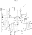
FIG. 1 is a diagram showing a schematic configuration of a thermal energy recovery device according to a first embodiment of the present invention, -
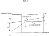
FIG. 2 is a graph showing temperature transitions of a working fluid and hot water in the thermal energy recovery device, -
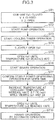
FIG. 3 is a chart showing a control operation of a startup operation of the thermal energy recovery device, -
FIG. 4 is a chart showing a control operation of a stop operation of the thermal energy recovery device, -
FIG. 5 is a diagram showing a schematic configuration of a thermal energy recovery device according to a modification of the first embodiment of the present invention, -
FIG. 6 is a diagram showing a schematic configuration of a thermal energy recovery device according to a second embodiment of the present invention, -
FIG. 7 is a graph showing temperature transitions of a working fluid and hot water in the thermal energy recovery device, -
FIG. 8 is a chart showing a control operation of a normal operation of the thermal energy recovery device, -
FIG. 9 is a diagram showing a schematic configuration of a thermal energy recovery device as a reference example, and -
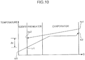
FIG. 10 is a graph showing temperature transitions of a working fluid and hot water in the reference example. - A thermal energy recovery device according to a first embodiment of the present invention is described with reference to the drawings.
- As shown in
FIG. 1 , the thermalenergy recovery device 1 includes a working fluid circulation flow path for circulating a working fluid while being accompanied by a phase change (hereinafter, merely referred to as a "circulation flow path") 22, a thermal fluidcirculation flow path 30 for circulating hot water serving as a pressurized heating fluid in a liquid state, and acontrol unit 50. - A
heater 32 is provided in the thermal fluidcirculation flow path 30. Thisheater 32 includes a heatingmedium flow path 32a in which a heating medium (high-temperature gas such as corrosive gas) in a gas phase flows and a thermalfluid flow path 32b in which hot water flows. The heating medium in the heatingmedium flow path 32a and the hot water in the thermalfluid flow path 32b exchange heat in theheater 32. In this way, the hot water is heated. The thermalenergy recovery device 1 recovers thermal energy of the heating medium. In therecovery device 1, this thermal energy of the heating medium is temporarily recovered in the hot water of the thermal fluidcirculation flow path 30. Since the thermal fluidcirculation flow path 30 is interposed between apipe 34 in which the heating medium flows and thecirculation flow path 22 in which the working fluid is circulated, the heating medium does not flow into later-describedevaporator 10 andpreheater 12 provided in thecirculation flow path 22. Thus, even if the heating medium is corrosive gas, the corrosion of theevaporator 10 and thepreheater 12 can be prevented. - The heating
medium flow path 32a is connected to aheating pipe 35 branched from thepipe 34 in which the heating medium flows. A flow rate of the heating medium flowing into theheater 32 can be adjusted by changing an opening of a flow rate control value Va1 provided in theheating pipe 35. Note that the flow rate control valve Va1 may be arranged upstream of theheater 32 in theheating pipe 35 or may be arranged downstream of theheater 32. - The
evaporator 10, thepreheater 12, anenergy recovery unit 13, acondenser 18 and apump 20 are provided in thecirculation flow path 22. - The
evaporator 10 includes afirst flow path 10a in which the working fluid flows and asecond flow path 10b in which the hot water flows. Theevaporator 10 performs heat exchange between the hot water in the thermal fluidcirculation flow path 30 and the working fluid (HFC245fa or the like) in thecirculation flow path 22. In this way, the working fluid evaporates. In this embodiment, a brazing plate type heat exchanger is used as theevaporator 10. However, a so-called shell-and-tube type heat exchanger may be used as theevaporator 10. - The
preheater 12 is arranged between theevaporator 10 and thepump 20 in thecirculation flow path 22. Thepreheater 12 includes afirst flow path 12a in which the working fluid flows and asecond flow path 12b in which the hot water flows. Thepreheater 12 performs heat exchange between the hot water flowing out from theevaporator 10 and the working fluid before flowing into theevaporator 10. In this way, the working fluid is heated. In this embodiment, a brazing plate type heat exchanger is used also as thepreheater 12. However, a so-called shell-and-tube heat exchanger may be used as thepreheater 12 as in the case of theevaporator 10. - In the first embodiment, an evaporation unit for evaporating the working fluid includes the
evaporator 10 and thepreheater 12 provided separately from theevaporator 10. However, there is no limitation to this. As shown inFIG. 5 , theevaporator 10 functioning as the evaporation unit may be provided, whereas the preheater may be omitted. - The
energy recovery unit 13 includes anexpander 14 and apower recovery device 16. Theexpander 14 is provided in a part of thecirculation flow path 22 downstream of theevaporator 10. Thus, thepreheater 12, theevaporator 10, theexpander 14, thecondenser 18 and thepump 20 are connected to thecirculation flow path 22 in this order. Theexpander 14 expands the working fluid in a gas phase flowing out from theevaporator 10. In this embodiment, a positive displacement screw expander including a rotor to be rotationally driven by expansion energy of the working fluid in a gas phase flowing out from theevaporator 10 is used as theexpander 14. Specifically, theexpander 14 includes a pair of male and female screw rotors. - The
power recovery device 16 is connected to theexpander 14. In this embodiment, a power generator is used as thepower recovery device 16. Thispower recovery device 16 includes a rotary shaft connected to one of the pair of screw rotors of theexpander 14. Thepower recovery device 16 generates power as the rotary shaft rotates according to the rotation of the screw rotor. Note that, instead of the power generator, a compressor or the like may be used as thepower recovery device 16. - An isolation valve V-1 is provided in a part of the
circulation flow path 22 between the evaporator 10 and theexpander 14. Further, abypass flow path 24 bypassing the isolation valve V-1 and theexpander 14 is provided in thecirculation flow path 22. An on-off valve V-2 is provided in thebypass flow path 24. - The
condenser 18 is provided in a part of thecirculation flow path 22 downstream of theexpander 14. Thecondenser 18 condenses (liquefies) the working fluid flowing out from theexpander 14 by cooling the working fluid with a cooling medium (cooling water or the like) supplied from outside. The cooling medium is supplied through a coolingmedium flow path 37, for example, from a cooling tower connected to the coolingmedium flow path 37. - The
pump 20 is provided in a part of thecirculation flow path 22 downstream of the condenser 18 (part between thecondenser 18 and the preheater 12). Thepump 20 pressurizes the working fluid in a liquid phase to a predetermined pressure and feeds the pressurized working fluid to thepreheater 12. A centrifugal pump including an impeller as a rotor, a gear pump including a rotor composed of a pair of gears, a screw pump, a trochoid pump or the like is used as thepump 20. - The heating fluid is sealed in a pressurized state in the thermal fluid
circulation flow path 30. Specifically, the hot water is sealed in a pressurized state in the thermal fluidcirculation flow path 30. Further, theevaporator 10, thepreheater 12, abuffer tank 38, afluid pump 40 and theheater 32 are arranged in this order in the thermal fluidcirculation flow path 30. The hot water successively flows through theevaporator 10, thepreheater 12, thebuffer tank 38, thefluid pump 40 and theheater 32. Thebuffer tank 38 is provided on a suction side of thefluid pump 40. By providing thebuffer tank 38, a predetermined pressure (head pressure) can be applied to the suction side of thefluid pump 40. - The thermal
energy recovery device 1 is provided with an inlet-side working fluid temperature sensor Tr1, an outlet-side working fluid temperature sensor Tr2, an inlet-side hot water temperature sensor Tw1 and an outlet-side hot water temperature sensor Tw2. The inlet-side working fluid temperature sensor Tr1 detects a temperature of the working fluid on an inlet side of the evaporation unit, i.e. thepreheater 12 and outputs a signal indicative of a detection value. The outlet-side working fluid temperature sensor Tr2 detects a temperature of the working fluid on an outlet side of the evaporation unit, i.e. theevaporator 10 and outputs a signal indicative of a detection value. The inlet-side hot water temperature sensor Tw1 detects a temperature of the hot water on an inlet side of the evaporation unit, i.e. theevaporator 10 and outputs a signal indicative of a detection value. The outlet-side hot water temperature sensor Tw2 detects a temperature of the hot water on an outlet side of the evaporation unit, i.e. thepreheater 12 and outputs a signal indicative of a detection value. - The signals output from these sensors Tr1, Tr2, Tw1 and Tw2 are input to the
control unit 50. Thecontrol unit 50 executes a suppression control for suppressing a temperature difference between the hot water and the working fluid in theevaporator 10 and thepreheater 12 during a startup operation of the thermalenergy recovery device 1. As shown inFIG. 2 , the temperature of the working fluid increases from a temperature tr1 on the inlet side of thepreheater 12 to a temperature tr3 by being heated by the hot water in thepreheater 12 and theevaporator 10. Then, the working fluid evaporated in theevaporator 10 is further heated in theevaporator 10 to reach a temperature tr2. In contrast, the temperature of the hot water gradually decreases from a temperature tw1 on the inlet side of theevaporator 10 and reaches a temperature tw2 on the outlet side of thepreheater 12. Since the working fluid undergoes a phase change in theevaporator 10, a temperature change amount is small. In contrast, a temperature change amount of the working fluid is large in thepreheater 12. Thus, a temperature difference Δt between the temperature tw2 of the hot water on the outlet side of thepreheater 12 and the temperature tr1 of the working fluid on the inlet side of thepreheater 12 increases. Particularly, since the temperature of the working fluid is low in some cases during the startup operation, the temperature difference Δt tends to increase and a thermal stress generated in thepreheater 12 possibly becomes problematic. - Accordingly, the
control unit 50 executes the suppression control for suppressing the temperature difference between the hot water and the working fluid in theevaporator 10 and thepreheater 12 during the startup operation. - Next, a control operation of the startup operation is described with reference to
FIG. 3 . During the startup operation for starting the thermalenergy recovery device 1, an operator first confirms that the flow rate control valve Va1 is closed, the isolation valve V-1 is closed and the on-off valve V-2 in thebypass flow path 24 is open (Step ST1). Then, the operator operates an unillustrated start button. In this way, thepump 20 and thefluid pump 40 start operating (Step ST2). Further, the operation of the cooling tower is started, whereby the cooling medium is supplied to thecondenser 18 through the cooling medium flow path 37 (Step ST3). - Subsequently, the
control unit 50 controls to slightly open the flow rate control valve Va1 (Step ST4). At this time, the opening is set at a value set in advance such as α %. Thecontrol unit 50 controls to gradually increase the opening of the flow rate control valve Va1 (Step ST5). In this way, the temperature of the hot water gradually increases. At this time, the temperature tw1 of the hot water on the inlet side of theevaporator 10 is monitored by the inlet-side hot water temperature sensor Tw1. Thecontrol unit 50 gradually increases the opening of the flow rate control valve Va1 until the temperature reaches an operation start temperature (e.g. 90°C) set in advance. However, the operation start temperature is not limited to 90°C and, for example, a range of about ±5°C is allowed. When the temperature tw1 of the hot water on the inlet side of theevaporator 10 reaches the operation start temperature, thecontrol unit 50 opens the isolation valve V-1 and closes the on-off valve V-2 in thebypass flow path 24. In this way, theexpander 14 is driven to start power recovery by the power recovery device 16 (Step ST6). Then, it is confirmed whether or not the operation (power generation) has been continuously stably performed for a given time (Step ST7). - After the drive of the
expander 14 is started, thecontrol unit 50 controls to gradually increases the opening of the flow rate control valve Va1 with the temperatures monitored by the respective temperature sensors Tr1, Tr2, Tw1 and Tw2 (Step ST8). At this time, a rate of increasing the opening of the flow rate control valve Va1 is so set that a temperature increase rate ΔT (C°/min) of the temperature tw1 of the hot water on the inlet side of theevaporator 10 is larger than a temperature increase rate when the temperature is below the operation start temperature. - In Step ST8, the temperature tw1 of the hot water on the inlet side of the
evaporator 10 is monitored and, if the temperature Tw1 of the hot water is below a temperature set in advance, thecontrol unit 50 gradually increases the opening of the flow rate control valve Va1 as described above. If the temperature Tw1 of the hot water is equal to or higher than the temperature set in advance, the temperature difference Δt between the temperature tw2 of the hot water on the outlet side of thepreheater 12 and the temperature tr1 of the working fluid on the inlet side of thepreheater 12 is also monitored. Then, thecontrol unit 50 executes the suppression control to gradually increase the opening of the flow rate control valve Va1 in such a range where the temperature difference Δt does not exceed a value set in advance. In this way, the temperature tw1 of the hot water on the inlet side of theevaporator 10 gradually increases and the temperature tw2 of the hot water on the outlet side of thepreheater 12 also gradually increases. On the other hand, the temperature difference Δt between the temperature tw2 and the temperature tr1 is suppressed to be equal to or lower than a predetermined temperature and does not become excessive. Specifically, an input heat quantity increase rate from the hot water in theevaporator 10 and thepreheater 12 is suppressed. Thus, a thermal stress by the thermal expansion of thepreheater 12 does not become excessive. Note that a rotation speed of thefluid pump 40 may also be adjusted in association with an opening adjustment of the flow rate control valve Va1. Specifically, the rotation speed of thefluid pump 40 may be adjusted to further finely adjust the temperature by the flow rate control valve Va1. - The
control unit 50 judges whether or not the temperature tw1 of the hot water on the inlet side of theevaporator 10 has reached an operating temperature (e.g. 130°C) set in advance (Step ST9) and the startup operation transitions to a normal operation by an automatic operation when the temperature Tw1 reaches the operating temperature (Step ST10). In the normal operation, the temperature tw1 of the hot water on the inlet side of theevaporator 10 is, for example, about 130°C, and the temperature of the hot water on the outlet side of theevaporator 10 is, for example, about 115°C. Further, the temperature tw2 of the hot water on the outlet side of thepreheater 12 is, for example, about 100°C. On the other hand, the temperature of the working fluid on the inlet side of thepreheater 12 is, for example, about 20°C at the start of the operation, but reaches, for example, about 40°C during the normal operation. The temperature of the working fluid on the outlet side of theevaporator 10 is, for example, about 120°C. -
FIG. 4 shows a stop flow during the automatic operation. As shown inFIG. 4 , when an emergency stop signal is issued (Step ST21), thecontrol unit 50 closes the isolation valve V-1 and opens the on-off valve V-2 in the bypass flow path 24 (Step ST22). In this way, the working fluid bypasses theexpander 14, wherefore power generation is stopped. Then, the flow rate control valve Va1 is closed (Step ST23). Since the temperature of the hot water circulating in the thermal fluidcirculation flow path 30 decreases in this way, the input heat quantities to theevaporator 10 and thepreheater 12 decrease. Then, thepump 20 and a hot water pump are stopped (Step ST24). At this time, the operation of the cooling tower is maintained (Step ST25). - As described above, in this embodiment, heat exchange is performed between the hot water introduced from the thermal fluid
circulation flow path 30 and the working fluid introduced from thecirculation flow path 22 in theevaporator 10 and thepreheater 12. Since the pressurized hot water in a liquid state flows into theevaporator 10 and thepreheater 12, thermal energy introduced to theevaporator 10 and thepreheater 12 is large. Thus, in the startup operation in which the temperature of the working fluid is relatively low, the suppression control is executed to suppress the temperature difference between the hot water and the working fluid in theevaporator 10 and thepreheater 12. Therefore, it can be suppressed that large thermal stresses are generated in theevaporator 10 and thepreheater 12 during the startup operation. - Further, in this embodiment, if the temperature of the hot water is equal to or higher than the predetermined temperature set in advance, the input heat quantities in the
evaporator 10 and thepreheater 12 are suppressed such that the temperature difference Δt between the temperature tw2 of the hot water on the outlet side of thepreheater 12 and the temperature tr1 of the working fluid on the inlet side of thepreheater 12 is equal to or lower than the predetermined temperature. Thus, it can be reliably suppressed that the thermal stresses in theevaporator 10 and thepreheater 12 become excessive at the start of the operation. Specifically, the temperature difference between the temperature tw2 of the hot water on the outlet side and the temperature tr1 of the working fluid on the inlet side is largest in thepreheater 12. Thus, by executing the suppression control on the basis of this temperature difference between the both, it can be reliably suppressed that the terminal stress in thepreheater 12 becomes excessive. - Further, in this embodiment, the
control unit 50 adjusts the opening of the flow rate control valve Va1 in the startup operation, whereby the temperature difference Δt between the temperature tw2 of the hot water on the outlet side and the temperature tr1 of the working fluid on the inlet side is maintained to be equal to or lower than the predetermined temperature. Thus, it can be suppressed that the thermal stress in thepreheater 12 becomes excessive by a simple operation of adjusting the opening of the flow rate control valve Va1. - Further, in this embodiment, the suppression control is executed to control the temperature difference Δt between the hot water and the working fluid in the startup operation. Thus, even if the temperature of the
preheater 12 is relatively low before the startup operation, a sudden temperature increase of thepreheater 12 can be suppressed. Therefore, it can be suppressed that the thermal stress generated in thepreheater 12 suddenly increases at the start of the operation. -
FIG. 6 shows a second embodiment of the present invention. Note that the same constituent elements as in the first embodiment are denoted by the same reference signs and the detailed description thereof is omitted here. - In the second embodiment, a cooler 53 is provided in a thermal fluid
circulation flow path 30 and a temperature difference Δt between a temperature tw2 of hot water on an outlet side of apreheater 12 and a temperature tr1 of a working fluid on an inlet side of thepreheater 12 is reduced by operating the cooler 53. - The cooler 53 is for reducing the temperature of the hot water through heat exchange between a cooling medium (air, water or the like) and the hot water. If air is used as the cooling medium, a
fan 54 for generating an air flow is provided. By driving thefan 54, the cooler 53 operates. In this way, the temperature difference Δt between the temperature tw2 of the hot water on the outlet side of thepreheater 12 and the temperature tr1 of the working fluid on the inlet side is controlled to or below a predetermined temperature. Note that if water is used as the cooling medium, an unillustrated pump is provided and the cooler 53 operates by driving the pump. - In the second embodiment, a temperature tw4 of the hot water on an inlet side of the
preheater 12 becomes lower than a temperature tw3 of the hot water on an outlet side of theevaporator 10 as shown inFIG. 7 by operating the cooler 53. In this way, the temperature difference Δt between the temperature tw2 of the hot water on the outlet side of thepreheater 12 and the temperature tr1 of the working fluid on the inlet side of thepreheater 12 is suppressed to be equal to or lower than the predetermined temperature. Note that the temperature of the hot water exhibits a temperature transition shown inFIG. 2 in a state where the cooler 53 is not operated. - In the thermal
energy recovery device 1 according to the second embodiment, whether or not the temperature difference Δt between the temperature tw2 of the hot water on the outlet side of thepreheater 12 and the temperature tr1 of the working fluid on the inlet side of thepreheater 12 is equal to or lower than the temperature set in advance during the normal operation is monitored by the control unit 50 (Step ST31) as shown inFIG. 8 . If the temperature difference Δt is judged to have exceeded the temperature set in advance, thecontrol unit 50 operates the cooler 53 (Step ST32). In this way, the temperature on the inlet side of thepreheater 12 decreases to reduce the temperature difference Δt between the temperature tw2 of the hot water on the outlet side of thepreheater 12 and the temperature tr1 of the working fluid on the inlet side of thepreheater 12. If the temperature difference Δt is further monitored and judged to be within the temperature set in advance, thecontrol unit 50 stops the cooler 53 (Step ST54). - As just described, in the second embodiment, the
control unit 50 operates the cooler 53 if the temperature difference Δt between the hot water and the working fluid exceeds the predetermined temperature. In this way, the temperature of the hot water flowing in the thermal fluidcirculation flow path 30 decreases. Thus, the temperature difference Δt between the hot water and the working fluid in thepreheater 12 can be reduced. - Note that the other configurations, functions and effects are not described, but are the same as in the first embodiment.
- Here, a reference example for reducing the temperature difference Δt between the temperature tw2 of the hot water on the outlet side of the
preheater 12 and the temperature tr1 of the working fluid on the inlet side of thepreheater 12 is mentioned. As shown inFIG. 9 , aregenerator 58 is provided between apump 20 and thepreheater 12 in acirculation flow path 22. This regenerator 58 heats the working fluid flowing from thepump 20 toward thepreheater 12 by the working fluid discharged from anexpander 14 and flowing toward acondenser 18. In this way, the temperature difference Δt in thepreheater 12 can be reduced by increasing the temperature of the working fluid before flowing into thepreheater 12. Specifically, as shown inFIG. 10 , if the temperature of the working fluid discharged from thepump 20 is tr0, this temperature reaches a temperature tr1 since the working fluid is heated by theregenerator 58 before flowing into thepreheater 12. As a result, the temperature difference Δt between the temperature tw2 of the hot water on the outlet side of thepreheater 12 and the temperature tr1 of the working fluid on the inlet side of thepreheater 12 is reduced. - Here, the above embodiments are outlined.
- (1) A thermal energy recovery device of the above embodiment includes a working fluid circulation flow path for circulating a working fluid, a thermal fluid circulation flow path for circulating a pressurized heating fluid in a liquid state, an evaporation unit for evaporating the working fluid flowing in the working fluid circulation flow path by heat of the heating fluid flowing in the thermal fluid circulation flow path, and a control unit for controlling a startup operation of the thermal energy recovery device. The control unit executes a suppression control for suppressing a temperature difference between the heating fluid and the working fluid in the evaporation unit in the startup operation.
In the above recovery device, since the pressurized heating fluid in a liquid state flows into the evaporation unit, thermal energy introduced to the evaporation unit is large. In the evaporation unit, heat exchange is performed between the heating fluid in a liquid state introduced from the thermal fluid circulation flow path and the working fluid introduced from the working fluid circulation flow path. Thus, in the startup operation in which the temperature of the working fluid is relatively low, the suppression control is executed to suppress the temperature difference between the heating fluid and the working fluid in the evaporation unit. Therefore, it can be suppressed that a large thermal stress is generated in the evaporation unit during the startup operation. - (2) The suppression control may be a control for setting a temperature difference between the heating fluid flowing out from the evaporation unit and the working fluid flowing into the evaporation unit equal to or lower than a predetermined temperature set in advance when the temperature of the heating fluid flowing into the evaporation unit is equal to or higher than a temperature set in advance.
In this mode, an input heat quantity in the evaporation unit is so suppressed that a temperature difference between the temperature of the heating fluid on an outlet side of the evaporation unit and the temperature of the working fluid on an inlet side of the evaporation unit becomes equal to or lower than the predetermined temperature when the temperature of the heating fluid is equal to or higher than the predetermined temperature set in advance. Thus, it can be reliably suppressed that the thermal stress in the evaporation unit becomes excessive during the startup operation. Specifically, the temperature difference between the temperature of the heating fluid on the outlet side and the temperature of the working fluid on the inlet side is largest in the evaporation unit. Thus, by executing the suppression control on the basis of this temperature difference between the both, it can be reliably suppressed that the thermal stress in the evaporation unit becomes excessive. - (3) The above thermal energy recovery device may include a heater provided in the thermal fluid circulation flow path for heating the heating fluid with heat of a heating medium in a gas state and a flow rate control valve for adjusting a flow rate of the heating medium introduced into the heater. In this case, the control unit may adjust an opening of the flow rate control valve such that the temperature difference between the heating fluid flowing out from the evaporation unit and the working fluid flowing into the evaporation unit is maintained to be equal to or lower than the predetermined temperature in the startup operation.
In this mode, the temperature difference is maintained to be equal to or lower than the predetermined temperature by the control unit adjusting the opening of the flow rate control valve in the startup operation. Thus, it can be suppressed that the thermal stress in the evaporation unit becomes excessive by a simple operation of adjusting the opening of the flow rate control valve. - (4) The above thermal energy recovery device may include a cooler for cooling the heating fluid flowing in the thermal fluid circulation flow path with a cooling medium. In this case, the control unit may operate the cooler to suppress the temperature difference between the heating fluid and the working fluid in the evaporation unit.
In this mode, the control unit operates the cooler, for example, when the temperature difference between the heating fluid and the working fluid in the evaporation unit exceeds the predetermined temperature. In this way, the temperature of the heating fluid flowing in the thermal fluid circulation flow path decreases. Thus, the temperature difference between the heating fluid and the working fluid in the evaporation unit can be reduced. - (5) The evaporation unit may include an evaporator for evaporating the working fluid by the heat of the heating fluid flowing in the thermal fluid circulation flow path and a preheater for heating the working fluid before flowing into the evaporator by the heat of the heating fluid flowing in the thermal fluid circulation flow path.
In this mode, thermal energy introduced to the preheater may increase, but the suppression control for suppressing the temperature difference between the heating fluid and the working fluid is executed in the startup operation. Thus, even if the temperature of the working fluid in the preheater is relatively low before the startup operation, a sudden temperature increase of the preheater can be suppressed. Therefore, a sudden increase of a thermal stress generated in the preheater at the start of the operation can be suppressed. - (6) A startup operation method for thermal energy recovery device of the above embodiment is a startup operation method for thermal energy recovery device with an evaporation unit for evaporating working fluid flowing in a working fluid circulation flow path by heat of a heating fluid flowing in a thermal fluid circulation flow path, wherein a suppression control for suppressing a temperature of the working fluid in the evaporation unit is executed in a startup operation of the thermal energy recovery device.
- (7) A heater for heating the heating fluid by heat of a heating medium in a gas state may be provided in the thermal fluid circulation flow path. In this case, in the above startup operation method for thermal energy recovery device, an opening of a flow rate control valve for adjusting a flow rate of the heating medium introduced into the heater may be adjusted such that a temperature difference between the heating fluid flowing out from the evaporation unit and the working fluid flowing into the evaporation unit is maintained to be equal to or lower than the predetermined temperature.
- (8) A cooler for cooling the heating fluid flowing in the thermal fluid circulation flow path by a cooling medium may be provided. In this case, the above startup operation method for thermal energy recovery device may include operating the cooler to suppress the temperature difference between the heating fluid and the working fluid in the evaporation unit if the temperature difference between the heating fluid flowing out from the evaporation unit and the working fluid flowing into the evaporation unit exceeds a temperature set in advance.
- As described above, a sudden increase of a thermal stress generated in the evaporation unit at the start of the operation can be suppressed.
Claims (8)
- A thermal energy recovery device, comprising:a working fluid circulation flow path for circulating a working fluid;a thermal fluid circulation flow path for circulating a pressurized heating fluid in a liquid state;an evaporation unit for evaporating the working fluid flowing in the working fluid circulation flow path by heat of the heating fluid flowing in the thermal fluid circulation flow path; anda control unit for controlling a startup operation of the thermal energy recovery device;the control unit executing a suppression control for suppressing a temperature difference between the heating fluid and the working fluid in the evaporation unit in the startup operation.
- A thermal energy recovery device according to claim 1, wherein the suppression control is a control for setting a temperature difference between the heating fluid flowing out from the evaporation unit and the working fluid flowing into the evaporation unit equal to or lower than a predetermined temperature set in advance when the temperature of the heating fluid flowing into the evaporation unit is equal to or higher than a temperature set in advance.
- A thermal energy recovery device according to claim 1 or 2, further comprising:a heater provided in the thermal fluid circulation flow path for heating the heating fluid with heat of a heating medium in a gas state; anda flow rate control valve for adjusting a flow rate of the heating medium introduced into the heater;wherein the control unit adjusts an opening of the flow rate control valve such that the temperature difference between the heating fluid flowing out from the evaporation unit and the working fluid flowing into the evaporation unit is maintained to be equal to or lower than the predetermined temperature in the startup operation.
- A thermal energy recovery device according to claim 1 or 2, further comprising a cooler for cooling the heating fluid flowing in the thermal fluid circulation flow path with a cooling medium,
wherein the control unit operates the cooler to suppress the temperature difference between the heating fluid and the working fluid in the evaporation unit. - A thermal energy recovery device according to claim 1, wherein the evaporation unit includes an evaporator for evaporating the working fluid by the heat of the heating fluid flowing in the thermal fluid circulation flow path and a preheater for heating the working fluid before flowing into the evaporator by the heat of the heating fluid flowing in the thermal fluid circulation flow path.
- A startup operation method for thermal energy recovery device with an evaporation unit for evaporating a working fluid flowing in a working fluid circulation flow path by heat of a heating fluid flowing in a thermal fluid circulation flow path, wherein:
a suppression control for suppressing a temperature of the working fluid in the evaporation unit is executed in a startup operation of the thermal energy recovery device. - A startup operation method for thermal energy recovery device according to claim 6, wherein:a heater for heating the heating fluid by heat of a heating medium in a gas state is provided in the thermal fluid circulation flow path; andan opening of a flow rate control valve for adjusting a flow rate of the heating medium introduced into the heater is adjusted in the suppression control such that a temperature difference between the heating fluid flowing out from the evaporation unit and the working fluid flowing into the evaporation unit is maintained to be equal to or lower than the predetermined temperature.
- A startup operation method for thermal energy recovery device according to claim 6, wherein:a cooler for cooling the heating fluid flowing in the thermal fluid circulation flow path by a cooling medium is provided; andthe startup operation method includes operating the cooler to suppress the temperature difference between the heating fluid and the working fluid in the evaporation unit if the temperature difference between the heating fluid flowing out from the evaporation unit and the working fluid flowing into the evaporation unit exceeds a temperature set in advance.
Applications Claiming Priority (2)
| Application Number | Priority Date | Filing Date | Title |
|---|---|---|---|
| JP2016234901A JP6718802B2 (en) | 2016-12-02 | 2016-12-02 | Thermal energy recovery device and start-up operation method thereof |
| PCT/JP2017/041132 WO2018101043A1 (en) | 2016-12-02 | 2017-11-15 | Thermal energy recovery device and startup operation method for same |
Publications (2)
| Publication Number | Publication Date |
|---|---|
| EP3536915A1 true EP3536915A1 (en) | 2019-09-11 |
| EP3536915A4 EP3536915A4 (en) | 2020-06-24 |
Family
ID=62241472
Family Applications (1)
| Application Number | Title | Priority Date | Filing Date |
|---|---|---|---|
| EP17875253.1A Withdrawn EP3536915A4 (en) | 2016-12-02 | 2017-11-15 | Thermal energy recovery device and startup operation method for same |
Country Status (6)
| Country | Link |
|---|---|
| US (1) | US10851678B2 (en) |
| EP (1) | EP3536915A4 (en) |
| JP (1) | JP6718802B2 (en) |
| KR (1) | KR20190086534A (en) |
| CN (1) | CN109996935A (en) |
| WO (1) | WO2018101043A1 (en) |
Family Cites Families (20)
| Publication number | Priority date | Publication date | Assignee | Title |
|---|---|---|---|---|
| JPS5799223A (en) * | 1980-12-10 | 1982-06-19 | Chiyoda Chem Eng & Constr Co Ltd | Power collector device from lng by rankin cycle and its start-up method |
| JPS5865917A (en) | 1981-10-15 | 1983-04-19 | Takuma Sogo Kenkyusho:Kk | Power generating device of exhaust heat recovery in diesel engine |
| JPS58104401A (en) | 1981-12-17 | 1983-06-21 | 株式会社東芝 | Method and device for controlling quantity of ventilation of steam generator |
| JPH0742844B2 (en) * | 1985-10-23 | 1995-05-15 | 株式会社東芝 | Hot water turbine plant |
| JPH01237309A (en) * | 1988-03-16 | 1989-09-21 | Hitachi Ltd | Generating equipment using lng cryogenic heat |
| IL114123A (en) * | 1994-06-14 | 2004-07-25 | Ormat Ind Ltd | Gas turbine system with heat recovery cycle and method for using the same |
| JP2007327661A (en) * | 2006-06-06 | 2007-12-20 | Babcock Hitachi Kk | Exhaust heat recovery boiler |
| US8245491B2 (en) * | 2006-11-15 | 2012-08-21 | Modine Manufacturing Company | Heat recovery system and method |
| US8528333B2 (en) * | 2007-03-02 | 2013-09-10 | Victor Juchymenko | Controlled organic rankine cycle system for recovery and conversion of thermal energy |
| EP2224164A1 (en) * | 2008-11-13 | 2010-09-01 | Siemens Aktiengesellschaft | Method of operating a waste heat steam generator |
| IT1399878B1 (en) * | 2010-05-13 | 2013-05-09 | Turboden Srl | ORC SYSTEM AT HIGH OPTIMIZED TEMPERATURE |
| IT1402363B1 (en) * | 2010-06-10 | 2013-09-04 | Turboden Srl | ORC PLANT WITH SYSTEM TO IMPROVE THE HEAT EXCHANGE BETWEEN THE SOURCE OF WARM FLUID AND WORK FLUID |
| US20120031096A1 (en) | 2010-08-09 | 2012-02-09 | Uop Llc | Low Grade Heat Recovery from Process Streams for Power Generation |
| EP2455658B1 (en) * | 2010-11-17 | 2016-03-02 | Orcan Energy AG | Method and device for vaporization of organic working media |
| DE102011004263A1 (en) * | 2011-02-17 | 2012-08-23 | Siemens Aktiengesellschaft | Method for operating a solar-heated waste heat steam generator and solar thermal waste heat steam generator |
| US20130160449A1 (en) * | 2011-12-22 | 2013-06-27 | Frederick J. Cogswell | Cascaded organic rankine cycle system |
| JP5891146B2 (en) | 2012-08-29 | 2016-03-22 | 株式会社神戸製鋼所 | Power generation device and method for controlling power generation device |
| DE102013011519A1 (en) * | 2013-07-09 | 2015-01-15 | Volkswagen Ag | Heat exchange device and drive unit for a motor vehicle |
| JP6194274B2 (en) * | 2014-04-04 | 2017-09-06 | 株式会社神戸製鋼所 | Waste heat recovery system and waste heat recovery method |
| FR3053105B1 (en) * | 2016-06-27 | 2018-06-15 | Fives Stein | INSTALLATION FOR RECOVERING CALORIFIC ENERGY ON A TUBULAR LONGERON OVEN AND CONVERTING IT WITH ELECTRICITY BY MEANS OF A TURBINE PRODUCING ELECTRICITY BY IMPLEMENTING A RANKINE CYCLE |
-
2016
- 2016-12-02 JP JP2016234901A patent/JP6718802B2/en not_active Expired - Fee Related
-
2017
- 2017-11-15 WO PCT/JP2017/041132 patent/WO2018101043A1/en not_active Ceased
- 2017-11-15 EP EP17875253.1A patent/EP3536915A4/en not_active Withdrawn
- 2017-11-15 KR KR1020197018208A patent/KR20190086534A/en not_active Abandoned
- 2017-11-15 US US16/464,696 patent/US10851678B2/en not_active Expired - Fee Related
- 2017-11-15 CN CN201780073212.4A patent/CN109996935A/en active Pending
Also Published As
| Publication number | Publication date |
|---|---|
| WO2018101043A1 (en) | 2018-06-07 |
| JP6718802B2 (en) | 2020-07-08 |
| KR20190086534A (en) | 2019-07-22 |
| US10851678B2 (en) | 2020-12-01 |
| CN109996935A (en) | 2019-07-09 |
| US20190383177A1 (en) | 2019-12-19 |
| EP3536915A4 (en) | 2020-06-24 |
| JP2018091216A (en) | 2018-06-14 |
Similar Documents
| Publication | Publication Date | Title |
|---|---|---|
| KR101708108B1 (en) | Waste heat recovery system and waste heat recovery method | |
| JP6670123B2 (en) | Exhaust heat recovery device and binary power generation device | |
| US7950230B2 (en) | Waste heat recovery apparatus | |
| CN110056405B (en) | Heat recovery device | |
| JP4302759B2 (en) | Waste heat utilization equipment | |
| EP2944812B1 (en) | Thermal energy recovery device and control method | |
| KR101708109B1 (en) | Waste heat recovery apparatus and waste heat recovery method | |
| JP5460663B2 (en) | Power generator | |
| JP6060040B2 (en) | Waste heat recovery device and operation control method of waste heat recovery device | |
| WO2014157300A1 (en) | Exhaust heat recovery device | |
| US10138842B2 (en) | Apparatus for utilizing heat wasted from engine | |
| US10060298B2 (en) | Thermal energy recovery device and start-up method thereof | |
| EP2918794B1 (en) | Rankine cycle device | |
| US10851678B2 (en) | Thermal energy recovery device and startup operation method for the same | |
| JP5653320B2 (en) | Waste heat regeneration system | |
| JP7412210B2 (en) | Rankine cycle device and its operating method | |
| CN108412561B (en) | Heat energy recovery device | |
| JP6616235B2 (en) | Waste heat recovery system | |
| JP2022025949A (en) | Binary power generation device |
Legal Events
| Date | Code | Title | Description |
|---|---|---|---|
| STAA | Information on the status of an ep patent application or granted ep patent |
Free format text: STATUS: THE INTERNATIONAL PUBLICATION HAS BEEN MADE |
|
| PUAI | Public reference made under article 153(3) epc to a published international application that has entered the european phase |
Free format text: ORIGINAL CODE: 0009012 |
|
| STAA | Information on the status of an ep patent application or granted ep patent |
Free format text: STATUS: REQUEST FOR EXAMINATION WAS MADE |
|
| 17P | Request for examination filed |
Effective date: 20190605 |
|
| AK | Designated contracting states |
Kind code of ref document: A1 Designated state(s): AL AT BE BG CH CY CZ DE DK EE ES FI FR GB GR HR HU IE IS IT LI LT LU LV MC MK MT NL NO PL PT RO RS SE SI SK SM TR |
|
| AX | Request for extension of the european patent |
Extension state: BA ME |
|
| DAV | Request for validation of the european patent (deleted) | ||
| DAX | Request for extension of the european patent (deleted) | ||
| A4 | Supplementary search report drawn up and despatched |
Effective date: 20200527 |
|
| RIC1 | Information provided on ipc code assigned before grant |
Ipc: F01K 13/02 20060101ALI20200519BHEP Ipc: F01K 25/10 20060101AFI20200519BHEP Ipc: F22B 1/18 20060101ALI20200519BHEP Ipc: F22B 1/16 20060101ALI20200519BHEP Ipc: F22B 35/00 20060101ALI20200519BHEP |
|
| STAA | Information on the status of an ep patent application or granted ep patent |
Free format text: STATUS: EXAMINATION IS IN PROGRESS |
|
| STAA | Information on the status of an ep patent application or granted ep patent |
Free format text: STATUS: THE APPLICATION HAS BEEN WITHDRAWN |
|
| 17Q | First examination report despatched |
Effective date: 20220727 |
|
| 18W | Application withdrawn |
Effective date: 20220823 |